EP3186552B2 - Appareil d'éclairage - Google Patents
Appareil d'éclairage Download PDFInfo
- Publication number
- EP3186552B2 EP3186552B2 EP15771313.2A EP15771313A EP3186552B2 EP 3186552 B2 EP3186552 B2 EP 3186552B2 EP 15771313 A EP15771313 A EP 15771313A EP 3186552 B2 EP3186552 B2 EP 3186552B2
- Authority
- EP
- European Patent Office
- Prior art keywords
- lighting fixture
- sheet
- metal
- cover
- light emitting
- Prior art date
- Legal status (The legal status is an assumption and is not a legal conclusion. Google has not performed a legal analysis and makes no representation as to the accuracy of the status listed.)
- Active
Links
Images


Classifications
-
- F—MECHANICAL ENGINEERING; LIGHTING; HEATING; WEAPONS; BLASTING
- F21—LIGHTING
- F21V—FUNCTIONAL FEATURES OR DETAILS OF LIGHTING DEVICES OR SYSTEMS THEREOF; STRUCTURAL COMBINATIONS OF LIGHTING DEVICES WITH OTHER ARTICLES, NOT OTHERWISE PROVIDED FOR
- F21V5/00—Refractors for light sources
- F21V5/007—Array of lenses or refractors for a cluster of light sources, e.g. for arrangement of multiple light sources in one plane
-
- F—MECHANICAL ENGINEERING; LIGHTING; HEATING; WEAPONS; BLASTING
- F21—LIGHTING
- F21S—NON-PORTABLE LIGHTING DEVICES; SYSTEMS THEREOF; VEHICLE LIGHTING DEVICES SPECIALLY ADAPTED FOR VEHICLE EXTERIORS
- F21S8/00—Lighting devices intended for fixed installation
- F21S8/08—Lighting devices intended for fixed installation with a standard
- F21S8/085—Lighting devices intended for fixed installation with a standard of high-built type, e.g. street light
- F21S8/086—Lighting devices intended for fixed installation with a standard of high-built type, e.g. street light with lighting device attached sideways of the standard, e.g. for roads and highways
-
- F—MECHANICAL ENGINEERING; LIGHTING; HEATING; WEAPONS; BLASTING
- F21—LIGHTING
- F21V—FUNCTIONAL FEATURES OR DETAILS OF LIGHTING DEVICES OR SYSTEMS THEREOF; STRUCTURAL COMBINATIONS OF LIGHTING DEVICES WITH OTHER ARTICLES, NOT OTHERWISE PROVIDED FOR
- F21V19/00—Fastening of light sources or lamp holders
- F21V19/001—Fastening of light sources or lamp holders the light sources being semiconductors devices, e.g. LEDs
- F21V19/003—Fastening of light source holders, e.g. of circuit boards or substrates holding light sources
-
- F—MECHANICAL ENGINEERING; LIGHTING; HEATING; WEAPONS; BLASTING
- F21—LIGHTING
- F21V—FUNCTIONAL FEATURES OR DETAILS OF LIGHTING DEVICES OR SYSTEMS THEREOF; STRUCTURAL COMBINATIONS OF LIGHTING DEVICES WITH OTHER ARTICLES, NOT OTHERWISE PROVIDED FOR
- F21V21/00—Supporting, suspending, or attaching arrangements for lighting devices; Hand grips
- F21V21/10—Pendants, arms, or standards; Fixing lighting devices to pendants, arms, or standards
- F21V21/116—Fixing lighting devices to arms or standards
-
- F—MECHANICAL ENGINEERING; LIGHTING; HEATING; WEAPONS; BLASTING
- F21—LIGHTING
- F21V—FUNCTIONAL FEATURES OR DETAILS OF LIGHTING DEVICES OR SYSTEMS THEREOF; STRUCTURAL COMBINATIONS OF LIGHTING DEVICES WITH OTHER ARTICLES, NOT OTHERWISE PROVIDED FOR
- F21V23/00—Arrangement of electric circuit elements in or on lighting devices
- F21V23/003—Arrangement of electric circuit elements in or on lighting devices the elements being electronics drivers or controllers for operating the light source, e.g. for a LED array
- F21V23/004—Arrangement of electric circuit elements in or on lighting devices the elements being electronics drivers or controllers for operating the light source, e.g. for a LED array arranged on a substrate, e.g. a printed circuit board
- F21V23/005—Arrangement of electric circuit elements in or on lighting devices the elements being electronics drivers or controllers for operating the light source, e.g. for a LED array arranged on a substrate, e.g. a printed circuit board the substrate is supporting also the light source
-
- F—MECHANICAL ENGINEERING; LIGHTING; HEATING; WEAPONS; BLASTING
- F21—LIGHTING
- F21V—FUNCTIONAL FEATURES OR DETAILS OF LIGHTING DEVICES OR SYSTEMS THEREOF; STRUCTURAL COMBINATIONS OF LIGHTING DEVICES WITH OTHER ARTICLES, NOT OTHERWISE PROVIDED FOR
- F21V23/00—Arrangement of electric circuit elements in or on lighting devices
- F21V23/003—Arrangement of electric circuit elements in or on lighting devices the elements being electronics drivers or controllers for operating the light source, e.g. for a LED array
- F21V23/007—Arrangement of electric circuit elements in or on lighting devices the elements being electronics drivers or controllers for operating the light source, e.g. for a LED array enclosed in a casing
- F21V23/008—Arrangement of electric circuit elements in or on lighting devices the elements being electronics drivers or controllers for operating the light source, e.g. for a LED array enclosed in a casing the casing being outside the housing of the lighting device
-
- F—MECHANICAL ENGINEERING; LIGHTING; HEATING; WEAPONS; BLASTING
- F21—LIGHTING
- F21V—FUNCTIONAL FEATURES OR DETAILS OF LIGHTING DEVICES OR SYSTEMS THEREOF; STRUCTURAL COMBINATIONS OF LIGHTING DEVICES WITH OTHER ARTICLES, NOT OTHERWISE PROVIDED FOR
- F21V23/00—Arrangement of electric circuit elements in or on lighting devices
- F21V23/04—Arrangement of electric circuit elements in or on lighting devices the elements being switches
- F21V23/0442—Arrangement of electric circuit elements in or on lighting devices the elements being switches activated by means of a sensor, e.g. motion or photodetectors
- F21V23/0464—Arrangement of electric circuit elements in or on lighting devices the elements being switches activated by means of a sensor, e.g. motion or photodetectors the sensor sensing the level of ambient illumination, e.g. dawn or dusk sensors
-
- F—MECHANICAL ENGINEERING; LIGHTING; HEATING; WEAPONS; BLASTING
- F21—LIGHTING
- F21V—FUNCTIONAL FEATURES OR DETAILS OF LIGHTING DEVICES OR SYSTEMS THEREOF; STRUCTURAL COMBINATIONS OF LIGHTING DEVICES WITH OTHER ARTICLES, NOT OTHERWISE PROVIDED FOR
- F21V23/00—Arrangement of electric circuit elements in or on lighting devices
- F21V23/04—Arrangement of electric circuit elements in or on lighting devices the elements being switches
- F21V23/0442—Arrangement of electric circuit elements in or on lighting devices the elements being switches activated by means of a sensor, e.g. motion or photodetectors
- F21V23/0471—Arrangement of electric circuit elements in or on lighting devices the elements being switches activated by means of a sensor, e.g. motion or photodetectors the sensor detecting the proximity, the presence or the movement of an object or a person
-
- F—MECHANICAL ENGINEERING; LIGHTING; HEATING; WEAPONS; BLASTING
- F21—LIGHTING
- F21V—FUNCTIONAL FEATURES OR DETAILS OF LIGHTING DEVICES OR SYSTEMS THEREOF; STRUCTURAL COMBINATIONS OF LIGHTING DEVICES WITH OTHER ARTICLES, NOT OTHERWISE PROVIDED FOR
- F21V31/00—Gas-tight or water-tight arrangements
- F21V31/005—Sealing arrangements therefor
-
- F—MECHANICAL ENGINEERING; LIGHTING; HEATING; WEAPONS; BLASTING
- F21—LIGHTING
- F21W—INDEXING SCHEME ASSOCIATED WITH SUBCLASSES F21K, F21L, F21S and F21V, RELATING TO USES OR APPLICATIONS OF LIGHTING DEVICES OR SYSTEMS
- F21W2131/00—Use or application of lighting devices or systems not provided for in codes F21W2102/00-F21W2121/00
- F21W2131/10—Outdoor lighting
- F21W2131/103—Outdoor lighting of streets or roads
-
- F—MECHANICAL ENGINEERING; LIGHTING; HEATING; WEAPONS; BLASTING
- F21—LIGHTING
- F21Y—INDEXING SCHEME ASSOCIATED WITH SUBCLASSES F21K, F21L, F21S and F21V, RELATING TO THE FORM OR THE KIND OF THE LIGHT SOURCES OR OF THE COLOUR OF THE LIGHT EMITTED
- F21Y2105/00—Planar light sources
- F21Y2105/10—Planar light sources comprising a two-dimensional [2D] array of point-like light-generating elements
-
- F—MECHANICAL ENGINEERING; LIGHTING; HEATING; WEAPONS; BLASTING
- F21—LIGHTING
- F21Y—INDEXING SCHEME ASSOCIATED WITH SUBCLASSES F21K, F21L, F21S and F21V, RELATING TO THE FORM OR THE KIND OF THE LIGHT SOURCES OR OF THE COLOUR OF THE LIGHT EMITTED
- F21Y2115/00—Light-generating elements of semiconductor light sources
- F21Y2115/10—Light-emitting diodes [LED]
Definitions
- Embodiments of the technology relate generally to lighting fixtures and more specifically to an outdoor luminaire, such as a streetlight, that comprises light emitting diodes and associated circuitry disposed against a metallic substrate.
- LEDs For illumination applications, light emitting diodes (LEDs) offer substantial potential benefit associated with their energy efficiency, light quality, and compact size. However, to realize the full potential of the potential benefits offered by light emitting diodes, new technologies are needed. For instance, relative to incandescent lights, light emitting diodes typically have different thermal properties, different electrical characteristics, different manufacturing requirements, and different mounting constraints.
- the lens frame may include a recessed support surface, a lens attachment area positioned outward from and peripherally of the support surface, and heat dissipating structure located peripherally of the support surface.
- a plurality of LEDs may be coupled to the support surface of the lens frame exteriorly of the luminaire housing and a lens may be coupled to the lens retaining area of the lens frame.
- US 2013 155 673 A1 relates to a street light having a lamp head including a housing and a plurality of LED light modules disposed within the housing.
- the LED light modules are separate and independent from each other and each include a cover having a plurality of openings. Each LED is aligned with and disposed within a respective one of the openings.
- a lighting fixture as in claim 1 is provided. Further embodiments are inter alia disclosed in the dependent claims.
- the lighting fixture according to claim 1 comprises an electrical circuit that is attached to a sheet of metal, with a layer of dielectric material positioned between the circuit and the sheet of metal.
- the layer of dielectric material can provide electrical insulation between the electrical circuit and the sheet of metal.
- the sheet of metal provides a ground plane for the electrical circuit.
- the sheet of metal provides electrical shielding for the electrical circuit.
- the sheet of metal may have a thickness in a range from approximately 0.0254 cm (0.01 inches) to approximately 0.635 cm (0.25 inches). Other embodiments may utilize other appropriate thicknesses that may be above or below that range, for example.
- the electrical circuit can provide electricity for one or more light emitting diodes.
- the circuit comprises the light emitting diodes, so that the light emitting diodes are mounted adjacent the sheet of metal.
- An array of light emitting diodes is attached to the sheet of metal, and the layer of dielectric material electrically insulates the light emitting diodes from the sheet of metal.
- Each light emitting diode has an associated optic that manages emitted light.
- An array of such optics is mounted adjacent an array of light emitting diodes.
- the array may be two dimensional in some embodiments, for example.
- a sheet of pliable material such as gasket material, is disposed between the array of optics and the layer of dielectric material to provide environmental protection, including to protect against moisture ingress.
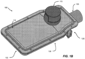
- Figures 1A , 1B , and 1C illustrate three views of an example lighting fixture 100 in accordance with some embodiments of the present disclosure.
- Figure 1A illustrates a perspective view of the underside of the lighting fixture 100.
- Figure 1B illustrates a perspective view of the top of the lighting fixture 100.
- Figure 1C illustrates a side view in perspective.
- the lighting fixture 100 comprises an outdoor luminaire, specifically a pole-mounted streetlight.
- a clamp 120 attaches the lighting fixture 100 to the end of a pole 105.
- the clamp 120 comprises a bracket 121 that provides vibration support.
- the lighting fixture 100 comprises an integral shroud 107 adjacent the clamp 120 that covers the end of the pole 105.
- the lighting fixture 100 comprises an array of light emitting diodes 126 for emitting light and a corresponding array of optics 125 for directing the emitted light to provide a desirable illumination pattern.
- a single light emitting diode may be utilized.
- a light shield 150 extends about the periphery of the array of optics 125.
- the light shield 150 prevents the emitted light from traveling skyward, thus suppressing light pollution.
- the light shield 150 occludes rays of light oriented in an unintended direction, for example skyward.
- the light shield 150 is a unitary element. In other embodiments, the light shield 150 comprises multiple components.
- a cover 110 provides environmental protection for the lighting fixture 100.
- the cover 110 further facilities thermal transfer of heat generated in connection with producing light from electricity.
- the cover 110 is a unitary element. In other embodiments, the cover 110 comprises multiple components.
- a photocontroller 115 is mounted on top of the cover 110.
- the photocontroller 115 senses ambient light level, turns the lighting fixture 100 on when the ambient light level is low, for example at dusk, and turns the lighting fixture 100 off in daylight conditions.
- the photocontroller 115 can comprise multiple sensors, including an occupancy sensor or personnel sensor, for example.
- the photocontroller 115 can be replaced by one or more other types of sensors, for example an occupancy sensor or personnel sensor.
- such an occupancy sensor may be mounted on the light emitting side of the lighting fixture, for example.
- the illustrated lighting fixture 100 further comprises a cover 130 on the fixture's light-emitting underside that provides an environmentally protected space for electrical elements.
- the cover 130 is a unitary element. In other embodiments, the cover 130 comprises multiple components.
- an opening 131 visible in Figures 3A and 3B ) that provides passage for lead wires.
- the opening has an associated grommet that helps avoid abrasion of the lead wires.
- one or more sensors can be mounted to the cover 130, for example an occupancy or personnel sensor that detects presence of one or more people utilizing passive infrared sensing or other appropriate technology.
- the cover 130 can comprise one or more holes, apertures, or windows for mounting such sensors, surge protection, and/or other appropriate devices. For example, such holes can be located in an area 132 of the cover 130 near the shroud 107.
- the cover 130 can have various electronic components mounted to the inside of the cover 130 or to the outside of the cover 130.
- the cover 130 has a recessed shape.
- the cover 130 has a substantially flat shape.
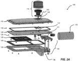
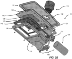
- Figures 2A and 2B illustrate two exploded views of the example lighting fixture 100 initially illustrated in Figure 1 and discussed above in accordance with some embodiments of the present disclosure.
- Figure 2A illustrates a side perspective view of the exploded assembly
- Figure 2B illustrates a bottom perspective view of the exploded assembly.
- a gasket 135 is located between the cover 110 and the sheet of metal 140.
- the gasket 135 provides environmental protection, including against moisture ingress.
- the sheet of metal 140 is flat or substantially flat. As discussed above, circuitry, including light emitting diodes 126, is mounted to the lower side of the sheet of metal 140. In some example embodiments, the sheet of metal 140 can comprise one or more recesses. In some example embodiments, the sheet of metal 140 is contoured on one or both sides, for example.
- the photocontroller 115 is mounted at the upper surface of the cover 110 as discussed above.
- a gasket 103 is located between the cover 110 and the photocontroller 115 and seals around the periphery of the photocontroller 115.
- the gasket 103 can prevent ingress of water or dust.
- a sheet of gasket material 145 is located between the array of optics 125 and the light shield 150, which functions as a frame.
- the sheet of gasket material 145 seals the light emitting diodes 126 and circuitry against moisture ingress.
- the light emitting diode circuit comprises circuitry printed on a layer of insulating material that has been coated on the sheet of metal 140.
- the circuitry may include light emitting diodes 126, electrical traces, and/or one or more light emitting diode drivers 109. At least the electrical traces are printed on the layer of insulating material that has been coated on the sheet of metal 140.
- the light shield 150 extends around the array of optics 125 and light emitting diodes 126 as discussed above.
- the cover 130 is located on the pole side of the array of optics 125 and can provide light shielding as well as an enclosed space.
- Figures 1 and 2 and discussed above in accordance with some embodiments of the present disclosure.
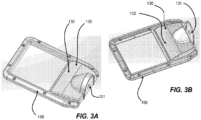
- Figure 3A illustrates a perspective view of the side of the integrated cover 130 and light shield 150 that faces outward when mounted on the lighting fixture 100 as illustrated in Figures 1 and 2 .
- Figure 3B illustrates a perspective view of the opposite side of the integrated cover 130 and light shield 150, which faces inward when mounted on the lighting fixture 100 as illustrated in Figures 1 and 2 .
- the inward facing side of the cover 130 is recessed to provide space for housing electrical components, including wiring.
- the gasket 145 extends around the periphery of the integrated cover 130 and light shield 150 to seal the space environmentally.
- the cover 130 provides an enclosed space that is under an opening 131 (illustrated in Figures 2A and 2B ) in the sheet of metal 140, and that opening 131 is aligned with the photocontroller 115 and the associated opening 132 in the cover 110. Accordingly, wiring feeds between the enclosed space of the cover 130 and the photocontroller 115. However in some embodiments, the cover 110 does not have such an opening.
- Figures 4A and 4B illustrate two views of the example lighting fixture 100 illustrated in Figures 1 and 2 and discussed above in accordance with some embodiments of the present disclosure.
- Figure 4A illustrates the lighting fixture 100 with the cover 110 removed to expose the sheet of metal 140.
- Figure 4B illustrates the lighting fixture 100 with the cover 110 attached.
- the cover 110 is slanted and contoured to prevent rainwater from accumulating on the top of the lighting fixture 100.
- the cover is formed to shed water, such as rainwater.
- FIGS 5A and 5B respectively illustrate perspective top and bottom views of the cover 110 in accordance with some example embodiments of the present disclosure.
- a gasket 135 can extend around the periphery of the cover 110 for environmental sealing.
- the cover 110 can comprise a gasket groove in which the gasket 110 is seated, for example.
- the cover 110 can comprise metal inserts for holding other components or for mounting.
- the cover 110 can comprise fastening elements molded or otherwise inserted.
- Figure 5 further illustrate the water-shedding contours that the cover 110 provides the lighting fixture 100 as discussed above. Additionally, Figure 5 shows a representative form for the portion of the cover 110 to which the photocontroller 115 is mounted as dis-cussed above.
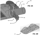
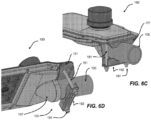
- Figures 6A, 6B , 6C, and 6D illustrate an example attachment system for mounting the lighting fixture 100 to the pole 105.
- Figure 6A illustrates a perspective view of the clamp 120 with the bracket 121 included.
- Figure 6B illustrates a perspective view of the bracket 121.
- Figure 6C illustrates another perspective view of the clamp 120 and the associated bracket 121.
- Figure 6D illustrates another perspective view of the clamp 120 and the associated bracket 121.
- the clamp 120 comprises bolts 191 that apply clamping force around the pole 105 in order to set and maintain the position of the lighting fixture 100 at the pole end.
- the bracket 121 is positioned on the upper side of the pole 105 and stabilizes the lighting fixture 100, including for vibration support.
- the collar 192 of the clamp 120 can accommodate poles 105 of varying diameters, as the bottom band that spans across one side of the pole is deformable relative to the upper member.
- the clamp 120 comprises a lower pole mounting plate with stamped-in ramps that allow the lighting fixture 100 to be mounted at multiple angles on the pole 105. See for example Figures 6A and 6B .
Landscapes
- Engineering & Computer Science (AREA)
- General Engineering & Computer Science (AREA)
- Microelectronics & Electronic Packaging (AREA)
- Arrangement Of Elements, Cooling, Sealing, Or The Like Of Lighting Devices (AREA)
- Non-Portable Lighting Devices Or Systems Thereof (AREA)
- Fastening Of Light Sources Or Lamp Holders (AREA)
Claims (9)
- Appareil d'éclairage (100) comprenant :une feuille de métal (140) comprenant un côté inférieur, un premier trou et un second trou, la feuille de métal (140) étant configurée pour recevoir une première vis (191) et une seconde vis (191) à une extrémité de montage du mât de la feuille de métal (140),dans lequel la première vis est reçue dans le premier trou et la seconde vis est reçue dans le second trou ;une série de diodes électroluminescentes (126) ;les traces électriques, et ;un pilote de diode électroluminescente (109) ;la série de diodes électroluminescentes (126), les traces électriques, et le pilote de diode électroluminescente (109) étant des éléments de circuit d'un circuit électrique qui est attaché à la feuille de métal (140), avec une couche de matériel diélectrique positionnée entre le circuit électrique et la feuille de métal (140), la couche de matériau diélectrique étant revêtue sur le côté inférieur de la feuille de métal (140), les éléments de circuit adhérant à la couche de matériau diélectrique, et le circuit électrique comprenant une circuiterie imprimée sur la couche de matériau diélectrique, la circuiterie comportant la série de diodes électroluminescentes (126), les traces électriques, et/ou le pilote de diode électroluminescente (109), au moins les traces électriques étant imprimées sur la couche de matériau diélectrique,dans lequel l'appareil d'éclairage (100) comprend en outre :une série d'éléments optiques (125) montée adjacente à la série de diodes électroluminescentes (126) de sorte que chaque élément optique soit associé à une diode électroluminescente ; etun collier de serrage (120) comprenant un support (121) et un collier (192) agencés pour être joints par la première vis (191) et la seconde vis (191) autour d'un mât de montage (105), le support (121) étant attaché au côté inférieur de la feuille de métal (140) par le biais d'assemblages boulonnés séparés de la première vis (191) et de la seconde vis (191), dans lequel le support (121) sert à fournir un appui antivibratoire, et dans lequel le collier de serrage (120) comprend la première vis (191) et la seconde vis (192) pour appliquer une force de serrage autour du mât de montage (105) afin de définir et maintenir une position de l'appareil d'éclairage (100) à l'extrémité du mât de montage (105).
- Appareil d'éclairage (100) selon la revendication 1, comprenant en outre :un matériau pliable disposé entre la série d'éléments optiques (125) et la couche de matériau diélectrique pour fournir une protection environnementale ; etune protection anti-coupure (150) s'étendant au moins partiellement à une périphérie de la série d'éléments optiques (125).
- Appareil d'éclairage (100) selon la revendication 2, comprenant en outre :un couvercle (110) monté adjacent à un second côté de la feuille de métal (140), avec un joint d'étanchéité disposé entre le couvercle (110) et la feuille de métal (140) ; etun dispositif de contrôle optique (115) monté sur le couvercle (110).
- Appareil d'éclairage (100) selon la revendication 1, comprenant en outre :
un capot (107) qui recouvre l'extrémité du mât de montage (105) - Appareil d'éclairage (100) selon la revendication 1, comprenant en outre un couvercle (110) qui est monté adjacent à un second côté de la feuille de métal (140) et qui est incliné par rapport à la feuille de métal (140) de sorte que les eaux de pluie s'écoulent du couvercle (110).
- Appareil d'éclairage (100) selon la revendication 1, dans lequel l'appareil d'éclairage 8100) comprend un lampadaire.
- Appareil d'éclairage (100) selon la revendication 1, comprenant en outre :
un couvercle en plastique (130) ou un couvercle en feuille de métal (130) ou un couvercle moulé (130) qui fournit un espace protégé de l'environnement pour un ou plusieurs des éléments électriques de l'appareil d'éclairage (100). - Appareil d'éclairage (100) selon la revendication 7, dans lequel un joint d'étanchéité s'étend autour d'une périphérie du couvercle en plastique (130) pour une protection contre l'humidité de l'un ou plusieurs éléments électriques, et
dans lequel le couvercle en plastique (130) comprend :une ouverture (131) à travers laquelle au moins une ligne électrique s'étend ; etun oeillet disposé à l'ouverture (131) pour protéger d'une incursion d'eau. - Appareil d'éclairage (100) selon la revendication 1, dans lequel la feuille de métal (140) présente une épaisseur dans une plage d'approximativement 0,0254 cm (0,01 pouce) à approximativement 0,381 cm (0,15 pouce), et
dans lequel l'appareil d'éclairage (100) comprend en outre :un capteur monté sur un couvercle (130) qui est disposé sur un côté électroluminescent de l'appareil d'éclairage (100) et qui fournit un espace protégé pour loger des dispositifs électriques,dans lequel le capteur fonctionne pour détecter la présence d'une personne.
Applications Claiming Priority (2)
| Application Number | Priority Date | Filing Date | Title |
|---|---|---|---|
| US201462042836P | 2014-08-28 | 2014-08-28 | |
| PCT/US2015/047169 WO2016033320A1 (fr) | 2014-08-28 | 2015-08-27 | Appareil d'éclairage |
Publications (3)
| Publication Number | Publication Date |
|---|---|
| EP3186552A1 EP3186552A1 (fr) | 2017-07-05 |
| EP3186552B1 EP3186552B1 (fr) | 2020-08-12 |
| EP3186552B2 true EP3186552B2 (fr) | 2023-08-30 |
Family
ID=54200049
Family Applications (1)
| Application Number | Title | Priority Date | Filing Date |
|---|---|---|---|
| EP15771313.2A Active EP3186552B2 (fr) | 2014-08-28 | 2015-08-27 | Appareil d'éclairage |
Country Status (5)
| Country | Link |
|---|---|
| US (2) | US10317060B2 (fr) |
| EP (1) | EP3186552B2 (fr) |
| CN (1) | CN106796005A (fr) |
| ES (1) | ES2822448T5 (fr) |
| WO (1) | WO2016033320A1 (fr) |
Families Citing this family (31)
| Publication number | Priority date | Publication date | Assignee | Title |
|---|---|---|---|---|
| USD736983S1 (en) * | 2014-05-23 | 2015-08-18 | Hubbell Incorporated | Floodlight luminaire |
| US12372219B2 (en) * | 2014-05-30 | 2025-07-29 | Cree Lighting Usa Llc | LED luminaire with a cavity, finned interior, and a curved outer wall extending from a surface on which the light source is mounted |
| AU361466S (en) * | 2015-03-09 | 2015-04-28 | Ningbo Yusing Optoelectronic Tech Co | Lights |
| USD765297S1 (en) * | 2015-06-12 | 2016-08-30 | Shuli Yang | Movable street lamp |
| USD770659S1 (en) * | 2015-07-28 | 2016-11-01 | Taizhou Jiaoguang Lighting Co., Ltd. | Street light |
| USD773096S1 (en) * | 2015-07-28 | 2016-11-29 | Taizhou Jiaoguang Lighting Co., Ltd. | Street light |
| USD770660S1 (en) * | 2015-07-30 | 2016-11-01 | Foxconn Technology Co., Ltd. | Street lamp |
| USD765298S1 (en) * | 2015-08-03 | 2016-08-30 | Schreder, S.A. | Outdoor lighting fixture |
| USD824071S1 (en) * | 2016-01-15 | 2018-07-24 | Philips Lighting Holding B.V. | Road lighting luminaire |
| USD851801S1 (en) * | 2016-08-12 | 2019-06-18 | Signify Holding B.V. | Public lighting fixture |
| USD843043S1 (en) * | 2016-08-12 | 2019-03-12 | Philips Lighting Holding B.V. | Public lighting fixture |
| USD851802S1 (en) * | 2016-08-12 | 2019-06-18 | Signify Holding B.V. | Public lighting fixture |
| USD843042S1 (en) * | 2016-08-18 | 2019-03-12 | Philips Lighting Holding B.V. | Streetlight |
| EP3312500B1 (fr) * | 2016-10-24 | 2020-06-17 | Simon Lighting, S.A. | Luminaire et couvercle de luminaire |
| USD856566S1 (en) * | 2017-03-31 | 2019-08-13 | Dongguan Pan American Electronics Co., Ltd | Shoebox light |
| TWD198512S (zh) * | 2017-10-13 | 2019-07-01 | Corvi Led Private Ltd | Led 路燈 |
| BE1025962B1 (fr) * | 2018-01-30 | 2019-08-28 | BEKA Schréder (Proprietary) Ltd | Boîtier de luminaire |
| USD909653S1 (en) * | 2018-09-15 | 2021-02-02 | Zhongshan Yinghao Solar Technology Co., Ltd | Integrated human induced street lamp |
| USD865256S1 (en) * | 2018-11-30 | 2019-10-29 | Shenzhen Moersen Lighting Technology Co., Ltd. | Solar lamp |
| US11092317B2 (en) * | 2019-06-20 | 2021-08-17 | TE Connectivity Services Gmbh | Light sensor receptacle connector mounting adaptor |
| US11187404B2 (en) * | 2019-10-11 | 2021-11-30 | TE Connectivity Services Gmbh | Lighting receptacle assembly for light fixture |
| EP3855066B2 (fr) * | 2020-01-24 | 2026-04-22 | Thorn Lighting Limited | Luminaire plat |
| WO2021209492A1 (fr) * | 2020-04-15 | 2021-10-21 | CommScope Connectivity Belgium BV | Dispositif et procédé de scellement de câbles dans des enceintes de télécommunications |
| US11204138B2 (en) * | 2020-05-20 | 2021-12-21 | Hampton Products International Corporation | Luminaire system facilitating modular enhancement |
| WO2022161784A1 (fr) * | 2021-01-28 | 2022-08-04 | Signify Holding B.V. | Dispositif de commande de luminaire pour des luminaires extérieurs |
| EP4341608B1 (fr) * | 2021-05-18 | 2025-07-09 | Signify Holding B.V. | Module pour le montage sur un luminaire |
| NL2031087B1 (en) * | 2022-02-25 | 2023-09-07 | Schreder Sa | Improved luminaire head for mounting on a pole |
| NL2033710B1 (en) * | 2022-11-24 | 2024-05-30 | Schreder Sa | Luminaire head assembly |
| EP4623246A1 (fr) * | 2022-11-24 | 2025-10-01 | Schreder S.A. | Ensemble tête de luminaire |
| WO2024149749A1 (fr) * | 2023-01-10 | 2024-07-18 | Signify Holding B.V. | Refroidissement durable pour pilotes de del haute puissance |
| EP4720566A1 (fr) | 2023-05-25 | 2026-04-08 | Signify Holding B.V. | Luminaire doté d'un boîtier flexible |
Citations (10)
| Publication number | Priority date | Publication date | Assignee | Title |
|---|---|---|---|---|
| US3387866A (en) † | 1966-02-16 | 1968-06-11 | Gen Electric | Luminaire |
| CA2390177A1 (fr) † | 2001-12-12 | 2003-06-12 | Genlyte Thomas Group Llc | Luminaire a montage universel |
| WO2009129232A1 (fr) † | 2008-04-14 | 2009-10-22 | Digital Lumens Incorporated | Systèmes d’éclairage modulaires |
| US20100309664A1 (en) † | 2009-06-05 | 2010-12-09 | Fu Zhun Precision Industry (Shen Zhen) Co., Ltd. | Led lamp |
| US8092049B2 (en) † | 2008-04-04 | 2012-01-10 | Ruud Lighting, Inc. | LED light fixture |
| US8092042B2 (en) † | 2007-05-03 | 2012-01-10 | Ruud Lighting, Inc. | Shield member in LED apparatus |
| US20120282815A1 (en) † | 2011-05-05 | 2012-11-08 | General Electric Company | Receptacle connector between controller and lighting fixture |
| US20140226331A1 (en) † | 2013-01-31 | 2014-08-14 | Cree, Inc. | Light-fixture support assembly |
| US8899786B1 (en) † | 2012-05-04 | 2014-12-02 | Cooper Technologies Company | Method and apparatus for light square assembly |
| US9108261B1 (en) † | 2011-07-27 | 2015-08-18 | Cooper Technologies Company | LED lighting heat sink and housing construction made by oven brazing technique |
Family Cites Families (12)
| Publication number | Priority date | Publication date | Assignee | Title |
|---|---|---|---|---|
| US20080123340A1 (en) * | 2006-11-27 | 2008-05-29 | Mcclellan Thomas | Light device having LED illumination and electronic circuit board in an enclosure |
| US8322881B1 (en) | 2007-12-21 | 2012-12-04 | Appalachian Lighting Systems, Inc. | Lighting fixture |
| KR100862540B1 (ko) * | 2008-04-25 | 2008-10-09 | 이위재 | 가로등용 엘이디 램프 |
| US8506127B2 (en) | 2009-12-11 | 2013-08-13 | Koninklijke Philips N.V. | Lens frame with a LED support surface and heat dissipating structure |
| CN102444793A (zh) * | 2010-10-07 | 2012-05-09 | 富准精密工业(深圳)有限公司 | 发光二极管灯具 |
| US20130015567A1 (en) * | 2010-10-21 | 2013-01-17 | Panasonic Corporation | Semiconductor device and production method for same |
| IES86115B2 (en) * | 2011-04-08 | 2013-01-02 | Adam Elliott | Improvements in and relating to roadway and street lighting apparatus and arrangement |
| GB2492761A (en) * | 2011-07-08 | 2013-01-16 | Vision Engineering Far East Ltd | Lighting assembly circuit board attached to a heat sink |
| EP2762766B1 (fr) * | 2011-10-02 | 2017-02-15 | Nanker (Guang Zhou) Semiconductor Manufacturing Corp. | Ensemble source photoélectrique à diodes électroluminescentes et lampe routière à diodes électroluminescentes améliorée par rapport à une lampe routière classique |
| US8702278B2 (en) | 2011-12-15 | 2014-04-22 | Tsmc Solid State Lighting Ltd. | LED lighting apparatus with flexible light modules |
| US8770797B2 (en) * | 2012-04-24 | 2014-07-08 | Chih-Chien Wang | Illumination device having heat dissipating means and light sensor |
| US8925884B2 (en) * | 2013-01-14 | 2015-01-06 | Cree, Inc. | Light fixture support assembly |
-
2015
- 2015-08-27 CN CN201580053949.0A patent/CN106796005A/zh active Pending
- 2015-08-27 EP EP15771313.2A patent/EP3186552B2/fr active Active
- 2015-08-27 US US14/837,597 patent/US10317060B2/en active Active
- 2015-08-27 WO PCT/US2015/047169 patent/WO2016033320A1/fr not_active Ceased
- 2015-08-27 ES ES15771313T patent/ES2822448T5/es active Active
-
2019
- 2019-06-10 US US16/436,421 patent/US10816179B2/en active Active
Patent Citations (10)
| Publication number | Priority date | Publication date | Assignee | Title |
|---|---|---|---|---|
| US3387866A (en) † | 1966-02-16 | 1968-06-11 | Gen Electric | Luminaire |
| CA2390177A1 (fr) † | 2001-12-12 | 2003-06-12 | Genlyte Thomas Group Llc | Luminaire a montage universel |
| US8092042B2 (en) † | 2007-05-03 | 2012-01-10 | Ruud Lighting, Inc. | Shield member in LED apparatus |
| US8092049B2 (en) † | 2008-04-04 | 2012-01-10 | Ruud Lighting, Inc. | LED light fixture |
| WO2009129232A1 (fr) † | 2008-04-14 | 2009-10-22 | Digital Lumens Incorporated | Systèmes d’éclairage modulaires |
| US20100309664A1 (en) † | 2009-06-05 | 2010-12-09 | Fu Zhun Precision Industry (Shen Zhen) Co., Ltd. | Led lamp |
| US20120282815A1 (en) † | 2011-05-05 | 2012-11-08 | General Electric Company | Receptacle connector between controller and lighting fixture |
| US9108261B1 (en) † | 2011-07-27 | 2015-08-18 | Cooper Technologies Company | LED lighting heat sink and housing construction made by oven brazing technique |
| US8899786B1 (en) † | 2012-05-04 | 2014-12-02 | Cooper Technologies Company | Method and apparatus for light square assembly |
| US20140226331A1 (en) † | 2013-01-31 | 2014-08-14 | Cree, Inc. | Light-fixture support assembly |
Also Published As
| Publication number | Publication date |
|---|---|
| US10816179B2 (en) | 2020-10-27 |
| EP3186552B1 (fr) | 2020-08-12 |
| US10317060B2 (en) | 2019-06-11 |
| ES2822448T5 (es) | 2024-03-04 |
| EP3186552A1 (fr) | 2017-07-05 |
| ES2822448T3 (es) | 2021-05-04 |
| WO2016033320A1 (fr) | 2016-03-03 |
| US20160061428A1 (en) | 2016-03-03 |
| US20190309935A1 (en) | 2019-10-10 |
| CN106796005A (zh) | 2017-05-31 |
Similar Documents
| Publication | Publication Date | Title |
|---|---|---|
| EP3186552B2 (fr) | Appareil d'éclairage | |
| EP3052855B1 (fr) | Feu de balisage comprenant une lentille | |
| TWI455375B (zh) | 發光二極體模組 | |
| US9651238B2 (en) | Thermally dissipated lighting system | |
| US9022603B1 (en) | Systems, methods, and devices for sealing LED light sources in a light module | |
| US20100085751A1 (en) | Enclosures for Light Sources | |
| KR100951650B1 (ko) | 엘이디 조명장치 | |
| US11041595B2 (en) | High mast luminaire | |
| KR20100018508A (ko) | Led 어레이 배선을 위한 보호 배열을 가진 다중 led 조명기구 | |
| US20180320885A1 (en) | Light module having a heatsink crimped around a lens, and a method for crimping a heat sink around a lens of a light module | |
| WO2012116163A2 (fr) | Éclairage vers le bas à base de led | |
| US20110038166A1 (en) | High efficiency heat dissipating device for lamps | |
| US20170089566A1 (en) | Illumination assembly, and light fixture including the same | |
| US9759418B2 (en) | Optical lens structures for light emitting diode (LED) array | |
| EP2949991A1 (fr) | Appareil d'éclairage à semi-conducteur optique | |
| WO2013046339A1 (fr) | Appareil d'éclairage | |
| JP5431612B1 (ja) | Led照明装置 | |
| JP4699828B2 (ja) | 面発光体及びこれを使用した内照式看板 | |
| KR101136675B1 (ko) | 감시카메라가 구비된 엘이디 보안등 장치 | |
| KR101591769B1 (ko) | 발광 다이오드 가로등 | |
| KR20150080693A (ko) | 경량화된 방열이 용이한 조명등 | |
| KR20100009474A (ko) | 엘이디 조명장치 | |
| US20150247620A1 (en) | Outdoor Lighting System | |
| EP3159607A1 (fr) | Éclairage en hauteur |
Legal Events
| Date | Code | Title | Description |
|---|---|---|---|
| STAA | Information on the status of an ep patent application or granted ep patent |
Free format text: STATUS: THE INTERNATIONAL PUBLICATION HAS BEEN MADE |
|
| PUAI | Public reference made under article 153(3) epc to a published international application that has entered the european phase |
Free format text: ORIGINAL CODE: 0009012 |
|
| STAA | Information on the status of an ep patent application or granted ep patent |
Free format text: STATUS: REQUEST FOR EXAMINATION WAS MADE |
|
| 17P | Request for examination filed |
Effective date: 20170320 |
|
| AK | Designated contracting states |
Kind code of ref document: A1 Designated state(s): AL AT BE BG CH CY CZ DE DK EE ES FI FR GB GR HR HU IE IS IT LI LT LU LV MC MK MT NL NO PL PT RO RS SE SI SK SM TR |
|
| AX | Request for extension of the european patent |
Extension state: BA ME |
|
| DAV | Request for validation of the european patent (deleted) | ||
| DAX | Request for extension of the european patent (deleted) | ||
| STAA | Information on the status of an ep patent application or granted ep patent |
Free format text: STATUS: EXAMINATION IS IN PROGRESS |
|
| 17Q | First examination report despatched |
Effective date: 20180130 |
|
| GRAP | Despatch of communication of intention to grant a patent |
Free format text: ORIGINAL CODE: EPIDOSNIGR1 |
|
| STAA | Information on the status of an ep patent application or granted ep patent |
Free format text: STATUS: GRANT OF PATENT IS INTENDED |
|
| INTG | Intention to grant announced |
Effective date: 20200304 |
|
| RAP1 | Party data changed (applicant data changed or rights of an application transferred) |
Owner name: EATON INTELLIGENT POWER LIMITED |
|
| RAP1 | Party data changed (applicant data changed or rights of an application transferred) |
Owner name: SIGNIFY HOLDING B.V. |
|
| GRAS | Grant fee paid |
Free format text: ORIGINAL CODE: EPIDOSNIGR3 |
|
| GRAA | (expected) grant |
Free format text: ORIGINAL CODE: 0009210 |
|
| STAA | Information on the status of an ep patent application or granted ep patent |
Free format text: STATUS: THE PATENT HAS BEEN GRANTED |
|
| AK | Designated contracting states |
Kind code of ref document: B1 Designated state(s): AL AT BE BG CH CY CZ DE DK EE ES FI FR GB GR HR HU IE IS IT LI LT LU LV MC MK MT NL NO PL PT RO RS SE SI SK SM TR |
|
| REG | Reference to a national code |
Ref country code: CH Ref legal event code: EP |
|
| REG | Reference to a national code |
Ref country code: IE Ref legal event code: FG4D |
|
| REG | Reference to a national code |
Ref country code: DE Ref legal event code: R096 Ref document number: 602015057378 Country of ref document: DE |
|
| REG | Reference to a national code |
Ref country code: AT Ref legal event code: REF Ref document number: 1301896 Country of ref document: AT Kind code of ref document: T Effective date: 20200915 |
|
| REG | Reference to a national code |
Ref country code: LT Ref legal event code: MG4D |
|
| REG | Reference to a national code |
Ref country code: NL Ref legal event code: MP Effective date: 20200812 |
|
| PG25 | Lapsed in a contracting state [announced via postgrant information from national office to epo] |
Ref country code: FI Free format text: LAPSE BECAUSE OF FAILURE TO SUBMIT A TRANSLATION OF THE DESCRIPTION OR TO PAY THE FEE WITHIN THE PRESCRIBED TIME-LIMIT Effective date: 20200812 Ref country code: LT Free format text: LAPSE BECAUSE OF FAILURE TO SUBMIT A TRANSLATION OF THE DESCRIPTION OR TO PAY THE FEE WITHIN THE PRESCRIBED TIME-LIMIT Effective date: 20200812 Ref country code: BG Free format text: LAPSE BECAUSE OF FAILURE TO SUBMIT A TRANSLATION OF THE DESCRIPTION OR TO PAY THE FEE WITHIN THE PRESCRIBED TIME-LIMIT Effective date: 20201112 Ref country code: GR Free format text: LAPSE BECAUSE OF FAILURE TO SUBMIT A TRANSLATION OF THE DESCRIPTION OR TO PAY THE FEE WITHIN THE PRESCRIBED TIME-LIMIT Effective date: 20201113 Ref country code: NO Free format text: LAPSE BECAUSE OF FAILURE TO SUBMIT A TRANSLATION OF THE DESCRIPTION OR TO PAY THE FEE WITHIN THE PRESCRIBED TIME-LIMIT Effective date: 20201112 Ref country code: HR Free format text: LAPSE BECAUSE OF FAILURE TO SUBMIT A TRANSLATION OF THE DESCRIPTION OR TO PAY THE FEE WITHIN THE PRESCRIBED TIME-LIMIT Effective date: 20200812 Ref country code: SE Free format text: LAPSE BECAUSE OF FAILURE TO SUBMIT A TRANSLATION OF THE DESCRIPTION OR TO PAY THE FEE WITHIN THE PRESCRIBED TIME-LIMIT Effective date: 20200812 |
|
| REG | Reference to a national code |
Ref country code: AT Ref legal event code: MK05 Ref document number: 1301896 Country of ref document: AT Kind code of ref document: T Effective date: 20200812 |
|
| PG25 | Lapsed in a contracting state [announced via postgrant information from national office to epo] |
Ref country code: PL Free format text: LAPSE BECAUSE OF FAILURE TO SUBMIT A TRANSLATION OF THE DESCRIPTION OR TO PAY THE FEE WITHIN THE PRESCRIBED TIME-LIMIT Effective date: 20200812 Ref country code: RS Free format text: LAPSE BECAUSE OF FAILURE TO SUBMIT A TRANSLATION OF THE DESCRIPTION OR TO PAY THE FEE WITHIN THE PRESCRIBED TIME-LIMIT Effective date: 20200812 Ref country code: LV Free format text: LAPSE BECAUSE OF FAILURE TO SUBMIT A TRANSLATION OF THE DESCRIPTION OR TO PAY THE FEE WITHIN THE PRESCRIBED TIME-LIMIT Effective date: 20200812 Ref country code: NL Free format text: LAPSE BECAUSE OF FAILURE TO SUBMIT A TRANSLATION OF THE DESCRIPTION OR TO PAY THE FEE WITHIN THE PRESCRIBED TIME-LIMIT Effective date: 20200812 Ref country code: IS Free format text: LAPSE BECAUSE OF FAILURE TO SUBMIT A TRANSLATION OF THE DESCRIPTION OR TO PAY THE FEE WITHIN THE PRESCRIBED TIME-LIMIT Effective date: 20201212 |
|
| REG | Reference to a national code |
Ref country code: CH Ref legal event code: PL |
|
| PG25 | Lapsed in a contracting state [announced via postgrant information from national office to epo] |
Ref country code: CH Free format text: LAPSE BECAUSE OF NON-PAYMENT OF DUE FEES Effective date: 20200831 Ref country code: CZ Free format text: LAPSE BECAUSE OF FAILURE TO SUBMIT A TRANSLATION OF THE DESCRIPTION OR TO PAY THE FEE WITHIN THE PRESCRIBED TIME-LIMIT Effective date: 20200812 Ref country code: DK Free format text: LAPSE BECAUSE OF FAILURE TO SUBMIT A TRANSLATION OF THE DESCRIPTION OR TO PAY THE FEE WITHIN THE PRESCRIBED TIME-LIMIT Effective date: 20200812 Ref country code: LU Free format text: LAPSE BECAUSE OF NON-PAYMENT OF DUE FEES Effective date: 20200827 Ref country code: LI Free format text: LAPSE BECAUSE OF NON-PAYMENT OF DUE FEES Effective date: 20200831 Ref country code: SM Free format text: LAPSE BECAUSE OF FAILURE TO SUBMIT A TRANSLATION OF THE DESCRIPTION OR TO PAY THE FEE WITHIN THE PRESCRIBED TIME-LIMIT Effective date: 20200812 Ref country code: RO Free format text: LAPSE BECAUSE OF FAILURE TO SUBMIT A TRANSLATION OF THE DESCRIPTION OR TO PAY THE FEE WITHIN THE PRESCRIBED TIME-LIMIT Effective date: 20200812 Ref country code: EE Free format text: LAPSE BECAUSE OF FAILURE TO SUBMIT A TRANSLATION OF THE DESCRIPTION OR TO PAY THE FEE WITHIN THE PRESCRIBED TIME-LIMIT Effective date: 20200812 |
|
| REG | Reference to a national code |
Ref country code: ES Ref legal event code: FG2A Ref document number: 2822448 Country of ref document: ES Kind code of ref document: T3 Effective date: 20210504 |
|
| REG | Reference to a national code |
Ref country code: DE Ref legal event code: R026 Ref document number: 602015057378 Country of ref document: DE |
|
| PLBI | Opposition filed |
Free format text: ORIGINAL CODE: 0009260 |
|
| PLAX | Notice of opposition and request to file observation + time limit sent |
Free format text: ORIGINAL CODE: EPIDOSNOBS2 |
|
| PG25 | Lapsed in a contracting state [announced via postgrant information from national office to epo] |
Ref country code: AT Free format text: LAPSE BECAUSE OF FAILURE TO SUBMIT A TRANSLATION OF THE DESCRIPTION OR TO PAY THE FEE WITHIN THE PRESCRIBED TIME-LIMIT Effective date: 20200812 Ref country code: AL Free format text: LAPSE BECAUSE OF FAILURE TO SUBMIT A TRANSLATION OF THE DESCRIPTION OR TO PAY THE FEE WITHIN THE PRESCRIBED TIME-LIMIT Effective date: 20200812 Ref country code: MC Free format text: LAPSE BECAUSE OF FAILURE TO SUBMIT A TRANSLATION OF THE DESCRIPTION OR TO PAY THE FEE WITHIN THE PRESCRIBED TIME-LIMIT Effective date: 20200812 |
|
| 26 | Opposition filed |
Opponent name: SCHOEPF, PATRICK Effective date: 20210512 |
|
| PG25 | Lapsed in a contracting state [announced via postgrant information from national office to epo] |
Ref country code: SK Free format text: LAPSE BECAUSE OF FAILURE TO SUBMIT A TRANSLATION OF THE DESCRIPTION OR TO PAY THE FEE WITHIN THE PRESCRIBED TIME-LIMIT Effective date: 20200812 |
|
| PG25 | Lapsed in a contracting state [announced via postgrant information from national office to epo] |
Ref country code: IE Free format text: LAPSE BECAUSE OF NON-PAYMENT OF DUE FEES Effective date: 20200827 Ref country code: SI Free format text: LAPSE BECAUSE OF FAILURE TO SUBMIT A TRANSLATION OF THE DESCRIPTION OR TO PAY THE FEE WITHIN THE PRESCRIBED TIME-LIMIT Effective date: 20200812 |
|
| PLBB | Reply of patent proprietor to notice(s) of opposition received |
Free format text: ORIGINAL CODE: EPIDOSNOBS3 |
|
| PG25 | Lapsed in a contracting state [announced via postgrant information from national office to epo] |
Ref country code: TR Free format text: LAPSE BECAUSE OF FAILURE TO SUBMIT A TRANSLATION OF THE DESCRIPTION OR TO PAY THE FEE WITHIN THE PRESCRIBED TIME-LIMIT Effective date: 20200812 Ref country code: MT Free format text: LAPSE BECAUSE OF FAILURE TO SUBMIT A TRANSLATION OF THE DESCRIPTION OR TO PAY THE FEE WITHIN THE PRESCRIBED TIME-LIMIT Effective date: 20200812 Ref country code: CY Free format text: LAPSE BECAUSE OF FAILURE TO SUBMIT A TRANSLATION OF THE DESCRIPTION OR TO PAY THE FEE WITHIN THE PRESCRIBED TIME-LIMIT Effective date: 20200812 |
|
| PG25 | Lapsed in a contracting state [announced via postgrant information from national office to epo] |
Ref country code: MK Free format text: LAPSE BECAUSE OF FAILURE TO SUBMIT A TRANSLATION OF THE DESCRIPTION OR TO PAY THE FEE WITHIN THE PRESCRIBED TIME-LIMIT Effective date: 20200812 |
|
| PG25 | Lapsed in a contracting state [announced via postgrant information from national office to epo] |
Ref country code: PT Free format text: LAPSE BECAUSE OF FAILURE TO SUBMIT A TRANSLATION OF THE DESCRIPTION OR TO PAY THE FEE WITHIN THE PRESCRIBED TIME-LIMIT Effective date: 20200812 |
|
| RAP4 | Party data changed (patent owner data changed or rights of a patent transferred) |
Owner name: SIGNIFY HOLDING B.V. |
|
| P01 | Opt-out of the competence of the unified patent court (upc) registered |
Effective date: 20230425 |
|
| PUAH | Patent maintained in amended form |
Free format text: ORIGINAL CODE: 0009272 |
|
| STAA | Information on the status of an ep patent application or granted ep patent |
Free format text: STATUS: PATENT MAINTAINED AS AMENDED |
|
| 27A | Patent maintained in amended form |
Effective date: 20230830 |
|
| AK | Designated contracting states |
Kind code of ref document: B2 Designated state(s): AL AT BE BG CH CY CZ DE DK EE ES FI FR GB GR HR HU IE IS IT LI LT LU LV MC MK MT NL NO PL PT RO RS SE SI SK SM TR |
|
| REG | Reference to a national code |
Ref country code: DE Ref legal event code: R102 Ref document number: 602015057378 Country of ref document: DE |
|
| REG | Reference to a national code |
Ref country code: ES Ref legal event code: DC2A Ref document number: 2822448 Country of ref document: ES Kind code of ref document: T5 Effective date: 20240304 |
|
| PGFP | Annual fee paid to national office [announced via postgrant information from national office to epo] |
Ref country code: ES Payment date: 20250916 Year of fee payment: 11 |
|
| PGFP | Annual fee paid to national office [announced via postgrant information from national office to epo] |
Ref country code: IT Payment date: 20250825 Year of fee payment: 11 |
|
| PGFP | Annual fee paid to national office [announced via postgrant information from national office to epo] |
Ref country code: GB Payment date: 20250826 Year of fee payment: 11 Ref country code: BE Payment date: 20250825 Year of fee payment: 11 |
|
| PGFP | Annual fee paid to national office [announced via postgrant information from national office to epo] |
Ref country code: FR Payment date: 20250825 Year of fee payment: 11 |
|
| PGFP | Annual fee paid to national office [announced via postgrant information from national office to epo] |
Ref country code: DE Payment date: 20251028 Year of fee payment: 11 |