EP3186431B1 - A steam iron head - Google Patents
A steam iron head Download PDFInfo
- Publication number
- EP3186431B1 EP3186431B1 EP15754221.8A EP15754221A EP3186431B1 EP 3186431 B1 EP3186431 B1 EP 3186431B1 EP 15754221 A EP15754221 A EP 15754221A EP 3186431 B1 EP3186431 B1 EP 3186431B1
- Authority
- EP
- European Patent Office
- Prior art keywords
- steam
- soleplate
- passageway
- iron head
- fluid
- Prior art date
- Legal status (The legal status is an assumption and is not a legal conclusion. Google has not performed a legal analysis and makes no representation as to the accuracy of the status listed.)
- Active
Links
- XEEYBQQBJWHFJM-UHFFFAOYSA-N Iron Chemical compound [Fe] XEEYBQQBJWHFJM-UHFFFAOYSA-N 0.000 title claims description 207
- 229910052742 iron Inorganic materials 0.000 title claims description 102
- 239000012530 fluid Substances 0.000 claims description 103
- 239000004744 fabric Substances 0.000 claims description 48
- 230000005494 condensation Effects 0.000 claims description 29
- 238000009833 condensation Methods 0.000 claims description 29
- 239000007788 liquid Substances 0.000 claims description 20
- XLYOFNOQVPJJNP-UHFFFAOYSA-N water Substances O XLYOFNOQVPJJNP-UHFFFAOYSA-N 0.000 description 57
- 238000000926 separation method Methods 0.000 description 27
- 230000002093 peripheral effect Effects 0.000 description 20
- 230000004888 barrier function Effects 0.000 description 8
- 238000010438 heat treatment Methods 0.000 description 8
- 239000000203 mixture Substances 0.000 description 8
- 239000002245 particle Substances 0.000 description 8
- 230000008859 change Effects 0.000 description 6
- 239000000463 material Substances 0.000 description 5
- 230000008901 benefit Effects 0.000 description 4
- 235000000396 iron Nutrition 0.000 description 4
- 238000009825 accumulation Methods 0.000 description 3
- 238000001704 evaporation Methods 0.000 description 3
- 230000008020 evaporation Effects 0.000 description 3
- 238000010409 ironing Methods 0.000 description 3
- 238000000034 method Methods 0.000 description 3
- 239000004743 Polypropylene Substances 0.000 description 2
- 239000004411 aluminium Substances 0.000 description 2
- XAGFODPZIPBFFR-UHFFFAOYSA-N aluminium Chemical compound [Al] XAGFODPZIPBFFR-UHFFFAOYSA-N 0.000 description 2
- 230000015572 biosynthetic process Effects 0.000 description 2
- 238000001816 cooling Methods 0.000 description 2
- 230000001419 dependent effect Effects 0.000 description 2
- -1 polypropylene Polymers 0.000 description 2
- 229920001155 polypropylene Polymers 0.000 description 2
- 230000008569 process Effects 0.000 description 2
- 239000002351 wastewater Substances 0.000 description 2
- 229910000838 Al alloy Inorganic materials 0.000 description 1
- 229910000861 Mg alloy Inorganic materials 0.000 description 1
- 239000004952 Polyamide Substances 0.000 description 1
- 229910052782 aluminium Inorganic materials 0.000 description 1
- 238000005108 dry cleaning Methods 0.000 description 1
- 230000000694 effects Effects 0.000 description 1
- 238000005265 energy consumption Methods 0.000 description 1
- 230000005484 gravity Effects 0.000 description 1
- 239000012212 insulator Substances 0.000 description 1
- 238000013021 overheating Methods 0.000 description 1
- 230000037361 pathway Effects 0.000 description 1
- 229920002647 polyamide Polymers 0.000 description 1
- 230000000717 retained effect Effects 0.000 description 1
- 239000010935 stainless steel Substances 0.000 description 1
- 229910001220 stainless steel Inorganic materials 0.000 description 1
- 230000037303 wrinkles Effects 0.000 description 1
Images


Classifications
-
- D—TEXTILES; PAPER
- D06—TREATMENT OF TEXTILES OR THE LIKE; LAUNDERING; FLEXIBLE MATERIALS NOT OTHERWISE PROVIDED FOR
- D06F—LAUNDERING, DRYING, IRONING, PRESSING OR FOLDING TEXTILE ARTICLES
- D06F75/00—Hand irons
- D06F75/02—Externally-heated hand irons; Hand irons internally heated by means other than electricity, e.g. by solid fuel, by steam
- D06F75/06—Externally-heated hand irons; Hand irons internally heated by means other than electricity, e.g. by solid fuel, by steam with means for supplying steam or liquid to the article being ironed
-
- D—TEXTILES; PAPER
- D06—TREATMENT OF TEXTILES OR THE LIKE; LAUNDERING; FLEXIBLE MATERIALS NOT OTHERWISE PROVIDED FOR
- D06F—LAUNDERING, DRYING, IRONING, PRESSING OR FOLDING TEXTILE ARTICLES
- D06F75/00—Hand irons
- D06F75/08—Hand irons internally heated by electricity
- D06F75/10—Hand irons internally heated by electricity with means for supplying steam to the article being ironed
- D06F75/12—Hand irons internally heated by electricity with means for supplying steam to the article being ironed the steam being produced from water supplied to the iron from an external source
-
- D—TEXTILES; PAPER
- D06—TREATMENT OF TEXTILES OR THE LIKE; LAUNDERING; FLEXIBLE MATERIALS NOT OTHERWISE PROVIDED FOR
- D06F—LAUNDERING, DRYING, IRONING, PRESSING OR FOLDING TEXTILE ARTICLES
- D06F75/00—Hand irons
- D06F75/08—Hand irons internally heated by electricity
- D06F75/10—Hand irons internally heated by electricity with means for supplying steam to the article being ironed
- D06F75/20—Arrangements for discharging the steam to the article being ironed
Definitions
- the present invention relates to a steam iron head.
- the present invention also relates to a domestic steam generator system iron having a steam iron head.
- Steam irons are used to remove creases from fabric, such as clothing and bedding.
- Steam irons comprise a body with a handle, so a user can manoeuvre the steam iron, and a soleplate which is placed in contact with the fabric to be ironed.
- the soleplate is heated to aid the removal of creases when ironing the fabric.
- the boiler in the base unit provides steam to the soleplate through a hose
- the soleplate is provided with an embedded heating element. Steam can condense when travelling through the hose and therefore, the heating element heats and maintains the soleplate at a desired temperature to help remove creases, evaporate condensed water, and prevent steam, supplied through holes in the soleplate, from condensing.
- steam irons are typically heavy due to, for example, the inclusion of the heating element to generate steam.
- the mass of the soleplate is typically high so that it can store more heat. This makes it difficult for the user to manoeuvre the steam iron for long periods of time.
- the energy consumption of the heating element also limits the steam output produced by the boiler of a steamer which reduces the effectiveness of the steam iron.
- a steam iron according to the prior art may be found in the documents EP 1 270 796 A1 , and US 3 414 993 A .
- a steam iron head comprising a soleplate having a fabric contact surface, a steam inlet through which steam flows to the steam iron head, at least one steam vent, and a steam passageway between the steam inlet and the at least one steam vent.
- the steam iron head also comprises a fluid separator between the steam passageway and the at least one steam vent configured to restrict flow of condensation formed in the steam passageway from passing through the at least one steam vent.
- the soleplate has a soleplate panel forming the fabric contact surface and a base of the steam passageway, and the soleplate panel is configured to be primarily heated by steam flowing along the steam passageway to the at least one steam vent.
- the temperature of the soleplate panel may be configured to decrease when the steam is not flowing along the steam passageway.
- the area of the base of the steam passageway may be at least 70% of the area of the fabric contact surface.
- the steam passageway may have a labyrinth configuration.
- the labyrinth configuration of the steam passageway guides steam on a predefined path ensuring that steam flows along a path extending along substantially all of the soleplate panel.
- the labyrinth configuration also forces steam to change direction which causes collisions between the surfaces defining the steam passageway and steam particles of the steam flow. In these collisions heat is transferred to the at least one wall from the steam. This encourages heat transfer and a uniform heat distribution.
- any condensed water is pushed by the steam towards the steam vents which minimises the accumulation of water in the steam passageway. This helps to prevent the formation of cold zones on the soleplate panel due to accumulation of water and further condensation.
- the steam passageway may extend in a spiralling pattern around the shape of the soleplate panel.
- a spiralling pattern helps to reduce the flow resistance in the steam passageway.
- the steam passageway may be defined by at least one wall upstanding from the soleplate panel.
- the thickness of the soleplate panel between the base and the fabric contact surface may be less than (or equal to) 2 mm.
- the mass of the soleplate may be minimised.
- the amount of energy needed to maintain the temperature of the soleplate panel is also reduced. Therefore, the user can use the steam iron head for longer periods and the condensation of steam inside the steam passageway is minimised.
- the fluid separator restricts condensation flowing from the steam vents to a fabric to be treated. Therefore, wet spots on the fabric may be prevented.
- the fluid separator helps to ensure that only dry steam exits the at least one steam vent. This helps to reduce the amount of 'spitting' that occurs during use of the steam iron head.
- any condensation formed in the steam passageway will pass through the fluid separator. It has been found that by heating the soleplate panel by steam with the above arrangement, it is possible for condensation to form in the steam passageway due to temperature variations over time of the soleplate panel. By providing a fluid separator, it is possible to ensure that the effect of condensation, for instance 'spitting' is minimised.
- the fluid separator comprises a cyclonic chamber.
- the fluid separator may be simple and light weight.
- the cyclonic chamber also provides a passive solution which is operational whenever there is a steam flow.
- a cyclonic chamber is also able to separate the fluids at high velocity.
- the steam iron head may further comprise a liquid removal arrangement configure to remove liquid separated from steam by the fluid separator.
- the fluid separator does not become full of water when the steam iron is used for long periods.
- the separated liquid is prevented from flooding the fluid separator and exiting onto the fabric being treated.
- the liquid removal arrangement restricts water from collecting and cooling which may cause further condensation of steam entering the fluid separator to occur.
- the liquid removal arrangement may comprise a return path to a liquid reservoir.
- Waste water can be re-used by returning it to a liquid reservoir in the steam generating unit. Therefore, the liquid reservoir does not have to be filled up as often which prolongs usage of the steam iron head between refills of the water reservoir.
- the liquid removal arrangement may comprise a heater to evaporate liquid separated from steam by the fluid separator.
- the condensed steam can be re-evaporated and used to treat the fabric. Therefore, there is no waste water that needs to be returned to the liquid reservoir. Furthermore, as the amount of condensed steam is small, only a small, low power heater is required and so the weight of the steam iron head may be minimised.
- the steam iron head may further comprise a user input connected to a steam valve configured to control the flow of steam through the steam passageway.
- the steam valve may be disposed between the steam inlet and the steam generator unit.
- the invention also relates to a steam generator system iron comprising the steam iron head as described above.
- the steam generator system iron may comprise a steam generator unit configured to provide pressurised steam.
- the steam generator unit can have a high steam rate. This enables the steam generator iron system to produce more steam for more effective ironing.
- the high steam pressure encourages steam to flow through the steam iron head.
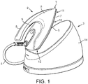
- a steam generator system iron 1 according to the invention is shown in Fig.1 . It comprises a steam iron head 2 and a steam generating unit 3.
- the steam iron head 2 and the steam generating unit 3 are fluidly connected by a hose 4.
- the hose 4 is flexible to enable a user to manoeuvre the steam iron head 2 easily.
- the hose 4 may be a sheath which wraps together at least one pipe or wires which extend from the steam iron head 2 to the steam generating unit 3.
- the steam iron head 2 comprises a housing 5 and a soleplate 6.
- the soleplate 6 comprises a soleplate panel 7.
- the soleplate panel 7 forms a lower end of the steam iron head 2.
- the housing 5 comprises a handle 8.
- the handle 8 enables the user to hold and manoeuvre the steam iron head 2.
- the steam iron head 2 also comprises a user input 9.
- the user input 9 is used to control the operation of a steam valve (not shown) which opens to provide the steam iron head 2 with steam from the steam generating unit 3.
- the soleplate 6 comprises a fabric contact surface 10.
- the fabric contact surface 10 is arranged to be placed against a fabric to be ironed.
- a lower side of the soleplate panel 7 defines the fabric contact surface 10.
- the soleplate 6 may further comprise a fabric contact plate (not shown).
- the fabric contact plate has a fabric contact surface (not shown) and a soleplate panel contact surface (not shown).
- the fabric contact plate may be a layer of material, for example, but not limited to aluminium or stainless steel, which has good thermal contact with the soleplate panel 7.
- the soleplate 6 has a front end 11 and a rear end 12.
- the soleplate 6 converges towards the front end 11. Therefore, the fabric contact surface 10 of the soleplate 6 has a generally triangular profile.
- the soleplate 6 may have alternative configurations.
- the hose 4 connects to the steam iron head 2 proximate to the rear end 12 of the soleplate 6.
- the steam generating unit 3 comprises a water reservoir 14 and a boiler (not shown). Water is fed to the boiler from the water reservoir 14. Water fed to the boiler is evaporated into steam. Steam generated by the boiler is then fed to the steam iron head 2 via the hose 4.
- the steam generator unit 3 may also be an instantaneous steam generator. Steam exits the soleplate 6 of the steam iron head 2 through at least one steam vent 49, shown in Fig.2 , towards the fabric to be ironed. The steam helps to increase the effectiveness of the steam iron head 2.
- the steam iron head 2 is shown without the housing 5, refer to Fig.1 , and with the front end 11 of the steam iron head 2 removed.
- the part of the steam iron head 2 shown in Fig.2 comprises the soleplate 6.
- An upper side of the soleplate panel 7 of the soleplate 6 comprises a top surface 15.
- the top surface 15 is distal to the fabric contact surface 10.
- the soleplate panel 7 comprises the fabric contact surface 10 and the top surface 15.
- the soleplate panel 7 has a thickness less than (or equal to) 2 mm.
- the thickness of the soleplate 7 panel may be greater than or equal to 0.5mm.
- the thickness of the soleplate panel 7 may be less than (or equal to) 0.8mm.
- a peripheral wall 16 upstands from the peripheral edge of the top surface 15 of the soleplate panel 7.
- the peripheral wall 16 extends around the perimeter of the soleplate panel 7.
- the peripheral wall 16 protrudes perpendicularly from the edge of the top surface 15.
- the peripheral wall 16 may protrude from the soleplate panel 7 at a different angle.
- the peripheral wall 16 is integrally formed with the soleplate panel 7.
- the steam iron head 2 further comprises an internal wall 17 which upstands from the top surface 15 of the soleplate panel 7.
- the internal wall 17 is integrally formed with the soleplate panel 7.
- a cover 18, shown in Fig.2 extends from the upper ends of the peripheral wall 16 and internal wall 17.
- the cover 18 is part of the soleplate 6.
- the cover 18 may be a bottom wall (not shown) of the housing 5 of the steam iron head 2.
- a steam passageway 19 extends along the soleplate 6.
- the steam passageway 19 defines a steam path along which steam is able to flow.
- the steam passageway 19 is formed by the soleplate panel 7, the peripheral wall 16, the internal wall 17, and the cover 18.
- the steam passageway 19 extends along the soleplate panel 7.
- the top surface 15 of the soleplate panel 7 defines a base 20 of the steam passageway 19.
- the peripheral wall 16 and internal wall 17 form side walls of the steam passageway 19.
- the cover 18 forms a top wall of the steam passageway 19.
- the soleplate panel 7, peripheral and internal walls 16, 17 and cover 18 form steam contact walls of the soleplate 6.
- a surface of the peripheral wall 16, the internal wall 17, the cover 18, and the base 20 form steam contact surfaces.
- steam flows into the steam passageway 19 in the steam iron head 2 via steam passageway inlet 21. Steam then flows along the steam passageway 19 and into a fluid separator 25. The fluid separator 25 separates water from the steam. Steam then exits the fluid separator 25 and passes through the steam vents 49 and onto the fabric being ironed.
- the internal wall 17 is a single wall. However, it will be understood that the internal wall 17 may have a plurality of spaced sections.
- the internal wall 17 upstands from the soleplate panel 7.
- the steam passageway 19 has a spiral arrangement. In the present arrangement this is formed by the internal wall 17 extending in a spiral arrangement.
- the path of the steam passageway 19 extends from the peripheral wall 16 towards the centre of the top surface 15 of the soleplate 6.
- the area of the base 20 of the steam passageway 19 substantially corresponds to the area of the fabric contact surface 10. That is, the base 20 and the fabric contact surface 10 have substantially the same surface area.
- the steam passageway 19 has a labyrinth configuration. That is, the steam does not flow from the steam passageway inlet 21 in a straight line directly to a steam passageway outlet 23.
- the steam passageway 19 changes direction at least once so that the direction of the steam flow is changed at least once. This enables steam to flow over a larger area of the top surface 15 of the soleplate panel 7.
- the labyrinth configuration also causes steam to collide with the steam contact surfaces 16, 17, 18, 20 heating up the soleplate 6.
- the labyrinth may be unicursal, i.e. have a single path, or multicursal, having multiple paths or branches.
- the labyrinth configuration of the steam passageway 19 is in the form of a spiralling pattern around the shape of the soleplate panel 7.
- the labyrinth configuration of the steam passageway 19 may be a single pathway along which steam flows from the rear end 12 of the steam iron head 2 towards the front end 11 and back multiple times whilst moving from the right side of the steam iron head 2 to the left.
- the steam passageway 19 is configured to extend across the whole of the top surface 15 of the soleplate panel 7. Therefore, steam from the steam generating unit 3 is passed substantially over the whole of the soleplate panel 7. This encourages a uniform heat distribution across the top surface 15 of the soleplate panel 7 which acts as the base 20 of the steam passageway 19.
- the uniform heat distribution helps to prevent localised cold spots on the base 20 of the steam passageway 19 that would condense steam flowing along the steam passageway 19.
- the spiral pattern labyrinth of the present embodiment helps to reduce the flow resistance in the steam passageway 19.
- the solitary passageway helps to prevent the accumulation of condensed water in the steam passageway 19.
- the steam passageway 19 has a generally rectangular cross-section, although it will be understood that the cross-section of the steam passageway 19 may be another shape, for example, but not limited to, circular, elliptical, or triangular. In the present embodiment, the steam passageway 19 is the solitary path that the steam must take when passing through the soleplate 6 of the steam iron head 2.
- the present invention is not limited to having a single internal wall 17 protruding from the top surface 15 of the soleplate panel 7. Furthermore, it will be understood that by using more than one internal wall 17, a single steam path can be created using a single steam passageway 19. Alternatively, more than one steam path through multiple steam passageways 19 can be created in the steam iron head 2 from the steam passageway inlet 21 to the at least one steam vent 49. It is possible to determine the suitable number of steam paths and corresponding walls needed for a specific embodiment.
- the soleplate 6 may further comprise a steam distribution channel (not shown) configured to allow steam to be distributed to multiple steam vents 49.
- the soleplate 6 comprises the steam passageway inlet 21.
- the steam passageway inlet 21 is in the cover 18.
- the steam passageway inlet 21 is located proximate to the rear end 12 of the soleplate 6.
- a steam delivery pipe 22 delivers steam from the steam generating unit 3 through the steam passageway inlet 21 into the steam passageway 19.
- the steam delivery pipe 22 extends through the hose 4 from a steam generating unit steam outlet (not shown).
- the steam delivery pipe 22 is flexible to enable the user to easily manoeuvre the steam iron head 2.
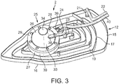
- the soleplate 6 comprises the steam passageway outlet 23. As shown in Fig.3 , the steam passageway outlet 23 is in the cover 18. The steam passageway outlet 23 is located centrally in the cover 18 of the soleplate 6. A steam transfer pipe 24 transfers steam out of the steam passageway 19 in the soleplate 6 and into the fluid separator 25.
- the soleplate 6 is heated up by the latent heat of the steam.
- the steam contact surfaces i.e. the base 20 of the steam passageway 19, the peripheral wall 16, the internal wall 17, and the cover 18, it transfers some of its heat energy to the soleplate 6.
- the top surface 15 of the soleplate panel 7 transfers the heat through the soleplate panel 7 to the fabric contact surface 10. In this way steam heats the soleplate 6 to the temperature of the steam.
- the steam passageway 19 distributes the steam substantially across the whole of the soleplate 6, the soleplate 6 heats up uniformly.
- energy from the steam is transferred to the steam contact surfaces 16, 17, 18, 20 which may cause some of the steam to condense in the steam passageway 19.
- the steam contact walls 7, 16, 17, 18, having steam contact surfaces 16, 17, 18, 20 that define the steam passageway 19 have a combined mass of less than 0.4kg in a typical embodiment.
- the steam contact walls 7, 16, 17, 18 may, for instance, have a combined mass of less than 0.3kg.
- the soleplate panel 7, and the peripheral and internal walls 16, 17 have a mass configured to minimise the amount of heat energy required to heat them up to the steam temperature.
- the material that the steam contact walls7, 16, 17, 18 are made from has a set density, in order to minimise the mass of the steam contact walls 7, 16, 17, 18 the amount of material used to make them is minimised.
- the soleplate panel 7, and peripheral and internal walls 16, 17 have a thickness as low as 0.5mm to minimise the mass.
- the mass of the steam contact walls 7, 16, 17, 18 minimises the amount of energy required to heat the soleplate 6 to the desired temperature.
- the steam contact surfaces 16, 17, 18, 20 will heat up to the same temperature as the steam quickly and so the amount of time in which condensation can occur in the steam passageway 19 is reduced. Therefore, the heat capacity of the steam iron head 2 is reduced.
- the soleplate panel 7, peripheral wall 16, and internal wall 17 are configured to heat up to the temperature of the steam and transfer the heat through the soleplate 6.
- the soleplate panel 7, peripheral wall 16, and internal wall 17 are formed from, for example, but not limited to aluminium or magnesium alloys.
- the cover 18 is configured to heat up to prevent condensation and to transfer heat through the soleplate 6, it can alternatively be configured to prevent heat escaping from the steam passageway 19 and into the housing 5 of the steam iron 2. In this way the cover 18 also acts as an insulator. Therefore, the cover 18 may be formed from a material with low thermal conductivity and density.
- the cover 18 may be formed from, for example, but not limited to polypropylene or polyamide.
- the cover 18 may have an insulating layer (not shown) formed from a material having a low thermal conductivity, such as, but not limited to EPP (expanded polypropylene). This helps to prevent heat escaping into the housing 5.
- the user operates the user input 9, refer to Fig.1 , to open the steam valve (not shown) and allow steam to flow along the steam passageway 19. Therefore, the soleplate 6 of the steam iron head 2 and steam will experience the largest difference in temperature at the point when the steam valve is opened and steam is first introduced into the steam passageway 19.
- the low mass, achieved by making the steam contact walls 7, 16, 17, 18 of the steam passageway 19 thin allows the temperature difference to be reduced quickly, preventing the formation of condensation and increasing the efficiency of the steam generator system iron 1.
- the steam valve (not shown) is disposed between the steam passageway inlet 21 and the exit of the steam generating unit 3.
- the steam valve may be disposed in the steam passageway inlet 21. Therefore, steam is not stored in the steam passageway 19.
- the steam valve is disposed at the exit of the steam generating unit 3 so that steam is not stored in the hose 4 further reducing the amount of condensation in the steam flow.
- the part of the steam iron head 2 shown in Fig.2 and Fig.3 comprises the fluid separator 25.
- the fluid separator 25 is located on top of the cover 18 on the longitudinal axis of the steam iron head 2.
- the fluid separator 25 is located between the steam passageway outlet 23 of the cover 18 and the front end 11 of the soleplate 6.
- the fluid separator 25 may be located in an alternative position on the cover 18 of the soleplate 6.
- the fluid separator 25 may be located within the soleplate 6.
- the fluid separator 25 comprises a casing formed of an upper casing 26 and a lower casing 27.
- the upper and lower casings 26, 27 are generally cylindrical.
- the upper and lower casing 26, 27 attach to each other via screws (not shown), or some other attachment arrangement, which extend through fixing holes 28 in an upper casing side wall 29 and a lower casing side wall 30 on the outer edge of the upper and lower casings 26, 27, respectively.
- the screws also fix the fluid separator 25 to the cover 18 of the soleplate 6.
- the upper and lower casings 26, 27 may be integrally formed.
- the upper casing 26 comprises a frusto-conical section 31.
- the frusto-conical section 31 protrudes from an upper cylindrical section 32 defined by the upper casing side wall 29.
- the upper casing is hollow. Therefore, the frusto-conical section 31 comprises a lateral wall 33 and a top wall 34.
- the cylindrical section 32 comprises the upper casing side wall 29.
- the lower casing 27 comprises a hollow lower cylindrical section which acts as a water collection section 35.
- the water collection section 35 comprises the lower casing side wall 30 and a base wall 36.
- the fluid separation chamber 37 is a cyclonic chamber.
- the upper casing 26 further comprises a fluid inlet 38.
- the fluid inlet 38 is located in the lateral wall 33 proximate to the top wall 34 of the upper casing 26.
- the fluid inlet 38 is connected to the steam transfer pipe 24.
- a fluid mixture of steam and condensation enters the fluid separator 25 from the steam passageway 19 in the soleplate 6 via the steam transfer pipe 24 and the fluid inlet 38.
- the fluid inlet 38 is positioned so that steam and condensation enters the fluid separation chamber 37, shown in Fig.4 , tangentially, with respect to the circular lateral wall 33, as will be explained in more detail hereinafter.
- the lower casing 27 of the fluid separator 25 further comprises a water outlet 39.
- the water outlet 39 is located in the lower casing side wall 30 proximate to the base wall 36.
- the water outlet 39 is connected to a water return pipe 40.
- the water return pipe 40 is flexible. This helps the user to manoeuvre the steam iron head 2 easily.
- the water return pipe 40 transfers water to the water reservoir 14 of the steam generating unit 3 through the hose 4, as will be described in more detail hereinafter.
- Fig.4 shows that the fluid separator 25 comprises a further outlet.
- the lower casing 27 comprises a dry steam outlet 41 in the base wall 36.
- the dry steam outlet 41 is formed by an aperture in the base wall 36. The aperture is located in the centre of the base wall 36.
- the dry steam outlet 41 is configured to prevent condensed steam from exiting the fluid separation chamber 37 through the dry steam outlet 41 and being discharged onto the fabric being ironed.
- an open ended cylindrical tube 42 protrudes perpendicularly from the base wall 36 towards the top wall 34 of the upper casing 26.
- the open ended cylindrical tube 42 defines a dry steam exit path 43 through the dry steam outlet 41.
- the open ended cylindrical tube 42 also protrudes perpendicularly downwards from the base wall 36.
- a gap 44 exists between a top end 45 of the open ended cylindrical tube 42 and the top wall 34 of the upper casing 26 so that steam can exit the fluid separation chamber 37 through the dry steam outlet 41.
- the steam is known as 'dry steam' because it contains a minimal amount of condensation.
- the fluid separator 25 is a cyclone chamber.
- the fluid separator 25 is able to separate steam from condensation by centrifugal force. Centrifugal force is caused by the inertia of a body; its resistance to change in motion.
- the fluid which is a mixture of steam and condensation, enters the fluid separation chamber 37 via the steam transfer pipe 24, refer to Fig.3 , and the fluid inlet 38 from the steam passageway 19 of the soleplate 6.
- the fluid entering the fluid separation chamber 37 is a mixture of steam and condensation because some of the steam heats up the soleplate 6 using its latent energy and therefore, condenses.
- the heat energy is transferred when the steam particles collide with the steam contact surfaces 16, 17, 18, 20 along the steam passageway 19. As heat is being transferred to the soleplate 6 some of the steam will condense and form water droplets.
- the fluid inlet 38 introduces the fluid into the fluid separation chamber 37 through the lateral wall 33 of the frusto-conical section 31 of the upper casing 26.
- the fluid inlet 38 introduces fluid into the frusto-conical section 31 tangentially. That is, the flow of the fluid is tangential to the lateral wall 33. Therefore, the fluid is instantly required to change direction when it enters the fluid separation chamber 37 because the frusto-conical section 31 has a circular cross-section.
- the upper casing 26 further comprises at least one rib 47 protruding from the inside surface 46 of the lateral wall 33.
- the ribs 47 extend at an angle to the direction of the fluid flow.
- the ribs 47 are configured to induce the fluid to flow in a downward helical path.
- the upper casing 26 also comprises a barrier 48.
- the barrier 48 protrudes perpendicularly from the top wall 34.
- the barrier 48 protrudes downwards towards the lower casing 27.
- the barrier 48 is circular.
- the barrier 48 is configured to prevent fluid that enters the fluid separation chamber 37 to exiting the fluid separation chamber 37 directly.
- the barrier 48 does not necessarily overlap the top end 45 of the open ended cylindrical tube 42 but it does have a larger radius of curvature.
- the fluid is prevented from going straight to the top end 45 of the open ended cylindrical tube 42 and along the dry steam exit path 43 to the dry steam outlet 41.
- the ribs 47 and the barrier 48 help to ensure that the fluid is separated and exits the fluid separation chamber 37
- the cross-sectional area of the frusto-conical section 31 increases towards the cylindrical section 32 of the upper casing 26.
- the fluid mixture of steam and condensation enters the fluid separation chamber 37 under high pressure which is generated in the steam generating unit 3 and released when the steam valve (not shown) is opened.
- the larger water droplets have less energy and are unable to remain mixed in the steam flow so they collate on the lateral wall 33 and fall to collect on the base wall 36.
- the steam still has enough energy to flow back up towards the top wall 34 of the upper casing 26.
- the advantage of having the opening of the dry steam exit path 43 proximate to the top wall 34 of the fluid separation chamber 37 is that the steam can not carry water collated on the bottom wall 36 to the dry steam outlet 41.
- the barrier 48 prevents water exiting the fluid separation chamber 37 straight from the fluid inlet 38.
- the build up of pressure in the fluid separation chamber 37 causes the steam to flow to the top end 45 of the open ended cylindrical tube 42.
- the pressure at the dry steam outlet 41 located at the opposing end of the open ended cylindrical tube 42 to the top end 45, is close to atmospheric. In the present embodiment, the pressure at the dry steam outlet 41 will be atmospheric. In an embodiment comprising the steam distribution channel (not shown the pressure at the dry steam outlet 41 is slightly higher than atmospheric. Therefore, the steam is drawn along the dry steam exit path 43.
- the steam is known as dry steam because all the water is in a gaseous state. That is, there is a minimal amount of water droplets present in the fluid.
- the water droplets which have been separated from the steam collect on the base wall 36 of the lower casing 27.
- the fluid separator 25 comprises a liquid removal arrangement to remove the water from the fluid separation chamber 37.
- the water is removed from the fluid separation chamber 37 through the water outlet 39 located in the lower casing side wall 30.
- the water travels through the water return pipe 40 to the water reservoir 14 in the steam generating unit 3.
- the water is returned to the steam generating unit 3 by utilising the high steam pressure present in the fluid separation chamber 37. The water can then be re-used.
- the fluid separator 25 is located on top of the cover 18 of the soleplate 6.
- the soleplate 6 further comprises the steam vent 49.
- the steam vent 49 is an aperture through which steam flows from the steam iron head 2, located directly beneath the centre of the water separator 25.
- the steam vent 49 fluidly communicates with the fluid separator 25. Therefore, the steam vent 49 fluidly communicates with the steam passageway 19 via the fluid separator 25.
- the steam vent 49 is configured to accommodate the bottom end of the open ended cylindrical tube 42 which defines the dry steam outlet 41.
- the steam vent 49 transfers dry steam from the dry steam exit path 43, via the dry steam outlet 41 of the fluid separator 25, through the soleplate 6 and onto the fabric to be ironed.
- the user switches on the steam generator system iron 1.
- the steam generating unit 3 then heats the water in the water reservoir 14.
- the user waits until the heater (not shown) in the steam generating unit 3 has evaporated a sufficient amount of water to build up sufficient pressure. This may be indicated by the switching on or off of a light (not shown) on the steam generating iron 1.
- the user then grips the steam iron head 2 by the handle 8 and places the fabric contact surface 10 of the soleplate 6 onto the fabric to be ironed.
- the user input 9 which opens the steam valve (not shown) allowing the steam to flow from the high pressure in the steam generating unit 3 towards the atmospheric pressure at the dry steam outlet 41 in the steam vent 49.
- the steam flows through the steam delivery pipe 22 and into the steam passageway 19 in the soleplate 6. As the steam flows through the steam delivery pipe 22 it loses heat to the environment and begins to condense.
- the high pressure of the steam forces it along the labyrinth style steam passageway 19.
- the steam flows along the steam passageway 19 that spirals inwards towards the centre of the soleplate 6.
- steam particles collide with the base wall 20 of the steam passageway 19, the peripheral wall 16, the internal wall 17, and the cover 18 of the soleplate 6.
- the steam particle transfers some of its heat to the steam contact surfaces 16, 17, 18, 20.
- the steam contact walls 7, 16, 17, 18 are thin to reduce the mass of the soleplate 6 and the heat energy required to raise its temperature. Therefore, the steam contact surfaces 16, 17, 18, 20 quickly reach the same temperature as the steam flowing through the steam passageway 19, thereby reducing the amount of condensation that occurs in the steam passageway 19.
- the high heat transfer coefficient allows the heat to be transferred around the soleplate 6 to enable parts of the steam passageway 19 that have not yet received the steam to heat up. This reduces the amount of condensation taking place further along the steam passageway 19.
- the soleplate 6 receives a uniform heat distribution because steam flows through the steam passageway 19 which extends over the whole of the top surface 15 of the soleplate 6. The heat is transferred through soleplate panel 7 from the top surface 15 to the fabric contact surface 10.
- the hot fabric contact surface 10 prevents any steam being used to treat the fabric being ironed from condensing on its surface and showing up as wet spots on the fabric.
- the soleplate 6 does not consume any power.
- the advantage of this is that a larger amount of power can be supplied to the steam generating unit 3.
- the steam generating unit 3 can use the power to produce a steam rate of between 60g/min and 200g/min.
- the steam generating unit 3 is configured to provide the steam iron head 2 with pressurised steam.
- the pressurised steam ensures the steam has sufficient velocity to enable the steam and condensed steam to be separated in the cyclonic chamber. Therefore, the performance of the steam iron head 2 can be enhanced.
- the soleplate 6 will not overheat as the maximum temperature it can reach is the temperature of the steam. Therefore, the steam iron head 2 is less likely to damage the fabric being ironed.
- the soleplate panel 7 is also configured to cool down once steam is no longer flowing along the steam passageway 19.
- the mixture of steam and condensation then flows into the fluid separator 25.
- the fluid mixture is separated using the principle of inertia as described in detail above.
- the heavier water droplets are flung towards the internal surface 46 of the fluid separation chamber 37 where they collate and run down into the water collection section 35 in the lower casing 27.
- a liquid removal arrangement removes the water and transfers it back to the water reservoir 14 to be re-used.
- the lighter steam particles are forced out of the fluid separation chamber 37 by the high pressure steam flowing into the fluid separator 25.
- the fluid mixture must rise towards the top wall 34 after being directed downwards by the ribs 47 only the steam has enough energy to exit the fluid separation chamber 37 via the dry steam exit path 43.
- the dry steam without any water droplets, is then discharged through the steam vent 49 in the soleplate 6 and onto the fabric to be cleaned. The user manoeuvres the steam iron head 2 across the fabric to distribute the steam and iron out wrinkles.
- the user can repeat this process by operating the user input 9 when more steam is needed to either heat the soleplate 6 or treat the fabric.
- the liquid removal arrangement may differ.
- the condensation may not be sent via the water return pipe 40 to the water reservoir 14 in the steam generating unit 3.
- the condensation may exit the fluid separation chamber 37 via the water outlet 39 and be transferred to a separate evaporation chamber (not shown).
- the evaporation chamber may comprise a low power heater (not shown).
- the low power heater may require less than (or equal to) 300W to be operated. Therefore, the steam iron head 2 can remain light-weight because the heater will be small.
- the water may be evaporated in the evaporation chamber by the lower power heater and then fed back into the fluid separation chamber 37 or directly onto the fabric via a steam vent.
- the low power heater may be embedded in the lower casing 27 of the water separator 25.
- the mass of the steam iron head 2 may be minimised.
- the mass of the steam iron head 2 may be less than 800g. It is envisaged that the steam iron head 2 will have a mass of between 400g and 800g inclusive. Therefore, the steam iron head 2 may weigh no more than 8N.
- the advantage of having a light steam iron head 2 is that the manoeuvrability of the steam iron head 2 is increased.
Description
- The present invention relates to a steam iron head. The present invention also relates to a domestic steam generator system iron having a steam iron head.
- Steam irons are used to remove creases from fabric, such as clothing and bedding. Steam irons comprise a body with a handle, so a user can manoeuvre the steam iron, and a soleplate which is placed in contact with the fabric to be ironed. The soleplate is heated to aid the removal of creases when ironing the fabric.
- Conventionally, the boiler in the base unit provides steam to the soleplate through a hose, and the soleplate is provided with an embedded heating element. Steam can condense when travelling through the hose and therefore, the heating element heats and maintains the soleplate at a desired temperature to help remove creases, evaporate condensed water, and prevent steam, supplied through holes in the soleplate, from condensing.
- However, steam irons are typically heavy due to, for example, the inclusion of the heating element to generate steam. In order to improve the efficiency of the steam generation, the mass of the soleplate is typically high so that it can store more heat. This makes it difficult for the user to manoeuvre the steam iron for long periods of time. The energy consumption of the heating element also limits the steam output produced by the boiler of a steamer which reduces the effectiveness of the steam iron.
- A steam iron according to the prior art may be found in the
documents EP 1 270 796 A1 , andUS 3 414 993 A . - It is commonly known in the dry cleaning service and other industrial laundry services to have steam irons that only use steam to remove creases from fabric. Pressurised steam is continuously circulated in a pressure chamber in order to maintain the high temperature of the steam iron. However, this is known to be inefficient and causes condensation.
- It is an object of the invention to provide a steam iron head which substantially alleviates or overcomes the problems mentioned above.
- The invention is defined by the independent claims; the dependent claims define advantageous embodiments.
- According to the present invention, there is provided a steam iron head comprising a soleplate having a fabric contact surface, a steam inlet through which steam flows to the steam iron head, at least one steam vent, and a steam passageway between the steam inlet and the at least one steam vent. The steam iron head also comprises a fluid separator between the steam passageway and the at least one steam vent configured to restrict flow of condensation formed in the steam passageway from passing through the at least one steam vent. The soleplate has a soleplate panel forming the fabric contact surface and a base of the steam passageway, and the soleplate panel is configured to be primarily heated by steam flowing along the steam passageway to the at least one steam vent.
- With this arrangement, it is possible to remove the need for a heater to heat the fabric contact surface to a sufficient operating temperature. This means that the weight of the steam iron head may be significantly minimised. This helps minimise the power consumption of the steam iron head. The latent heat released during condensation of steam in the soleplate is so large that the temperature of the fabric contact surface can be maintained relatively constant, even during the ironing process. Therefore, the efficiency and effectiveness of the steam iron head is maximised.
- The temperature of the soleplate panel may be configured to decrease when the steam is not flowing along the steam passageway.
- This means that overheating of the soleplate panel may be restricted.
- The area of the base of the steam passageway may be at least 70% of the area of the fabric contact surface.
- Therefore, it is possible to provide a uniform heat distribution across the soleplate panel as substantially all the soleplate panel is exposed to steam flowing through the steam passageway. Furthermore, the need for a heater to heat the soleplate is removed and the weight of the steam iron head can be minimised allowing the user to use the iron for longer without tiring.
- The steam passageway may have a labyrinth configuration.
- The labyrinth configuration of the steam passageway guides steam on a predefined path ensuring that steam flows along a path extending along substantially all of the soleplate panel. The labyrinth configuration also forces steam to change direction which causes collisions between the surfaces defining the steam passageway and steam particles of the steam flow. In these collisions heat is transferred to the at least one wall from the steam. This encourages heat transfer and a uniform heat distribution. In the labyrinth configuration, any condensed water is pushed by the steam towards the steam vents which minimises the accumulation of water in the steam passageway. This helps to prevent the formation of cold zones on the soleplate panel due to accumulation of water and further condensation.
- The steam passageway may extend in a spiralling pattern around the shape of the soleplate panel.
- By extending in a spiralling pattern around the shape of the soleplate panel, a continuous path can be formed to cover the soleplate panel. Therefore, the efficiency of the soleplate panel can be maximised. A spiralling pattern helps to reduce the flow resistance in the steam passageway.
- The steam passageway may be defined by at least one wall upstanding from the soleplate panel.
- With this arrangement, heat energy transferred to the walls may be conducted to the soleplate panel. Furthermore, condensation in the steam passageway may be minimised.
- The thickness of the soleplate panel between the base and the fabric contact surface may be less than (or equal to) 2 mm.
- By minimising the thickness of the soleplate panel, the mass of the soleplate may be minimised. The amount of energy needed to maintain the temperature of the soleplate panel is also reduced. Therefore, the user can use the steam iron head for longer periods and the condensation of steam inside the steam passageway is minimised.
- The fluid separator restricts condensation flowing from the steam vents to a fabric to be treated. Therefore, wet spots on the fabric may be prevented. The fluid separator helps to ensure that only dry steam exits the at least one steam vent. This helps to reduce the amount of 'spitting' that occurs during use of the steam iron head.
- As the fluid separator is between the steam passageway and the at least one steam vent., any condensation formed in the steam passageway will pass through the fluid separator. It has been found that by heating the soleplate panel by steam with the above arrangement, it is possible for condensation to form in the steam passageway due to temperature variations over time of the soleplate panel. By providing a fluid separator, it is possible to ensure that the effect of condensation, for instance 'spitting' is minimised.
- The fluid separator comprises a cyclonic chamber.
- Therefore, the fluid separator may be simple and light weight. The cyclonic chamber also provides a passive solution which is operational whenever there is a steam flow. A cyclonic chamber is also able to separate the fluids at high velocity.
- The steam iron head may further comprise a liquid removal arrangement configure to remove liquid separated from steam by the fluid separator.
- Therefore, the fluid separator does not become full of water when the steam iron is used for long periods. The separated liquid is prevented from flooding the fluid separator and exiting onto the fabric being treated. Furthermore, the liquid removal arrangement restricts water from collecting and cooling which may cause further condensation of steam entering the fluid separator to occur.
- The liquid removal arrangement may comprise a return path to a liquid reservoir.
- Waste water can be re-used by returning it to a liquid reservoir in the steam generating unit. Therefore, the liquid reservoir does not have to be filled up as often which prolongs usage of the steam iron head between refills of the water reservoir.
- The liquid removal arrangement may comprise a heater to evaporate liquid separated from steam by the fluid separator.
- The condensed steam can be re-evaporated and used to treat the fabric. Therefore, there is no waste water that needs to be returned to the liquid reservoir. Furthermore, as the amount of condensed steam is small, only a small, low power heater is required and so the weight of the steam iron head may be minimised.
- The steam iron head may further comprise a user input connected to a steam valve configured to control the flow of steam through the steam passageway.
- This means that the user is able to control when steam flows through the soleplate to be used to heat the soleplate or treat the fabric. Furthermore, the heat energy in the steam is not wasted in continuously heating the soleplate when it is not in use and/or needed.
- The steam valve may be disposed between the steam inlet and the steam generator unit.
- With this arrangement, steam is restricted from being retained in the steam passageway and cooling when steam flow is prevented. This restricts steam from condensing in the steam passageway.
- The invention also relates to a steam generator system iron comprising the steam iron head as described above.
- The steam generator system iron may comprise a steam generator unit configured to provide pressurised steam.
- Therefore, the steam generator unit can have a high steam rate. This enables the steam generator iron system to produce more steam for more effective ironing. The high steam pressure encourages steam to flow through the steam iron head.
- These and other aspects of the invention will be apparent from and elucidated with reference to the embodiments described hereinafter.
- Embodiments of the invention will now be described, by way of example only, with reference to the accompanying drawings, in which:
-
Fig.1 shows a schematic perspective view of a steam generator system iron according to the invention having a steam iron head; -
Fig.2 shows a schematic perspective view of part of the steam iron head ofFig.1 with a front portion of the steam iron head cut-away to show the internal structure and a section of a cover cut away; -
Fig.3 shows a schematic cut-away perspective view of part of the steam iron head ofFig.1 with the cover omitted; and -
Fig.4 shows a schematic cross-sectional side view of a fluid separator of the steam iron head ofFig.1 . - A steam
generator system iron 1 according to the invention is shown inFig.1 . It comprises asteam iron head 2 and asteam generating unit 3. Thesteam iron head 2 and thesteam generating unit 3 are fluidly connected by ahose 4. Thehose 4 is flexible to enable a user to manoeuvre thesteam iron head 2 easily. Thehose 4 may be a sheath which wraps together at least one pipe or wires which extend from thesteam iron head 2 to thesteam generating unit 3. Thesteam iron head 2 comprises ahousing 5 and asoleplate 6. Thesoleplate 6 comprises asoleplate panel 7. Thesoleplate panel 7 forms a lower end of thesteam iron head 2. - The
housing 5 comprises a handle 8. The handle 8 enables the user to hold and manoeuvre thesteam iron head 2. Thesteam iron head 2 also comprises auser input 9. Theuser input 9 is used to control the operation of a steam valve (not shown) which opens to provide thesteam iron head 2 with steam from thesteam generating unit 3. - The
soleplate 6 comprises afabric contact surface 10. Thefabric contact surface 10 is arranged to be placed against a fabric to be ironed. A lower side of thesoleplate panel 7 defines thefabric contact surface 10. In an alternative embodiment, thesoleplate 6 may further comprise a fabric contact plate (not shown). The fabric contact plate has a fabric contact surface (not shown) and a soleplate panel contact surface (not shown). The fabric contact plate may be a layer of material, for example, but not limited to aluminium or stainless steel, which has good thermal contact with thesoleplate panel 7. - The
soleplate 6 has afront end 11 and arear end 12. Thesoleplate 6 converges towards thefront end 11. Therefore, thefabric contact surface 10 of thesoleplate 6 has a generally triangular profile. However, it will be understood that thesoleplate 6 may have alternative configurations. Thehose 4 connects to thesteam iron head 2 proximate to therear end 12 of thesoleplate 6. - The
steam generating unit 3 comprises awater reservoir 14 and a boiler (not shown). Water is fed to the boiler from thewater reservoir 14. Water fed to the boiler is evaporated into steam. Steam generated by the boiler is then fed to thesteam iron head 2 via thehose 4. Thesteam generator unit 3 may also be an instantaneous steam generator. Steam exits thesoleplate 6 of thesteam iron head 2 through at least onesteam vent 49, shown inFig.2 , towards the fabric to be ironed. The steam helps to increase the effectiveness of thesteam iron head 2. - Referring to
Fig.2 , thesteam iron head 2 is shown without thehousing 5, refer toFig.1 , and with thefront end 11 of thesteam iron head 2 removed. The part of thesteam iron head 2 shown inFig.2 comprises thesoleplate 6. An upper side of thesoleplate panel 7 of thesoleplate 6 comprises atop surface 15. Thetop surface 15 is distal to thefabric contact surface 10. Thesoleplate panel 7 comprises thefabric contact surface 10 and thetop surface 15. Thesoleplate panel 7 has a thickness less than (or equal to) 2 mm. The thickness of thesoleplate 7 panel may be greater than or equal to 0.5mm. The thickness of thesoleplate panel 7 may be less than (or equal to) 0.8mm. - A
peripheral wall 16 upstands from the peripheral edge of thetop surface 15 of thesoleplate panel 7. Theperipheral wall 16 extends around the perimeter of thesoleplate panel 7. In the present embodiment, theperipheral wall 16 protrudes perpendicularly from the edge of thetop surface 15. However, it will be understood that in an alternative embodiment theperipheral wall 16 may protrude from thesoleplate panel 7 at a different angle. Theperipheral wall 16 is integrally formed with thesoleplate panel 7. - The
steam iron head 2 further comprises aninternal wall 17 which upstands from thetop surface 15 of thesoleplate panel 7. Theinternal wall 17 is integrally formed with thesoleplate panel 7. Acover 18, shown inFig.2 , extends from the upper ends of theperipheral wall 16 andinternal wall 17. Thecover 18 is part of thesoleplate 6. Alternatively, thecover 18 may be a bottom wall (not shown) of thehousing 5 of thesteam iron head 2. Asteam passageway 19 extends along thesoleplate 6. Thesteam passageway 19 defines a steam path along which steam is able to flow. Thesteam passageway 19 is formed by thesoleplate panel 7, theperipheral wall 16, theinternal wall 17, and thecover 18. Thesteam passageway 19 extends along thesoleplate panel 7. - The
top surface 15 of thesoleplate panel 7 defines abase 20 of thesteam passageway 19. Theperipheral wall 16 andinternal wall 17 form side walls of thesteam passageway 19. Thecover 18 forms a top wall of thesteam passageway 19. Thesoleplate panel 7, peripheral andinternal walls soleplate 6. A surface of theperipheral wall 16, theinternal wall 17, thecover 18, and the base 20 form steam contact surfaces. - In the present embodiment, steam flows into the
steam passageway 19 in thesteam iron head 2 viasteam passageway inlet 21. Steam then flows along thesteam passageway 19 and into afluid separator 25. Thefluid separator 25 separates water from the steam. Steam then exits thefluid separator 25 and passes through the steam vents 49 and onto the fabric being ironed. - In the present embodiment, the
internal wall 17 is a single wall. However, it will be understood that theinternal wall 17 may have a plurality of spaced sections. Theinternal wall 17 upstands from thesoleplate panel 7. Thesteam passageway 19 has a spiral arrangement. In the present arrangement this is formed by theinternal wall 17 extending in a spiral arrangement. The path of thesteam passageway 19 extends from theperipheral wall 16 towards the centre of thetop surface 15 of thesoleplate 6. The area of thebase 20 of thesteam passageway 19 substantially corresponds to the area of thefabric contact surface 10. That is, thebase 20 and thefabric contact surface 10 have substantially the same surface area. - Referring to
Fig.3 , thesteam passageway 19 has a labyrinth configuration. That is, the steam does not flow from thesteam passageway inlet 21 in a straight line directly to asteam passageway outlet 23. Thesteam passageway 19 changes direction at least once so that the direction of the steam flow is changed at least once. This enables steam to flow over a larger area of thetop surface 15 of thesoleplate panel 7. The labyrinth configuration also causes steam to collide with the steam contact surfaces 16, 17, 18, 20 heating up thesoleplate 6. The labyrinth may be unicursal, i.e. have a single path, or multicursal, having multiple paths or branches. In the present embodiment, the labyrinth configuration of thesteam passageway 19 is in the form of a spiralling pattern around the shape of thesoleplate panel 7. - For example, the labyrinth configuration of the
steam passageway 19 may be a single pathway along which steam flows from therear end 12 of thesteam iron head 2 towards thefront end 11 and back multiple times whilst moving from the right side of thesteam iron head 2 to the left. - In the present embodiment, as shown in
Fig.2 andFig.3 , thesteam passageway 19 is configured to extend across the whole of thetop surface 15 of thesoleplate panel 7. Therefore, steam from thesteam generating unit 3 is passed substantially over the whole of thesoleplate panel 7. This encourages a uniform heat distribution across thetop surface 15 of thesoleplate panel 7 which acts as thebase 20 of thesteam passageway 19. - The uniform heat distribution helps to prevent localised cold spots on the
base 20 of thesteam passageway 19 that would condense steam flowing along thesteam passageway 19. - The spiral pattern labyrinth of the present embodiment, shown in
Fig.2 andFig.3 , helps to reduce the flow resistance in thesteam passageway 19. The solitary passageway helps to prevent the accumulation of condensed water in thesteam passageway 19. - The
steam passageway 19 has a generally rectangular cross-section, although it will be understood that the cross-section of thesteam passageway 19 may be another shape, for example, but not limited to, circular, elliptical, or triangular. In the present embodiment, thesteam passageway 19 is the solitary path that the steam must take when passing through thesoleplate 6 of thesteam iron head 2. - However, it will be understood that the present invention is not limited to having a single
internal wall 17 protruding from thetop surface 15 of thesoleplate panel 7. Furthermore, it will be understood that by using more than oneinternal wall 17, a single steam path can be created using asingle steam passageway 19. Alternatively, more than one steam path throughmultiple steam passageways 19 can be created in thesteam iron head 2 from thesteam passageway inlet 21 to the at least onesteam vent 49. It is possible to determine the suitable number of steam paths and corresponding walls needed for a specific embodiment. In an alternative embodiment, thesoleplate 6 may further comprise a steam distribution channel (not shown) configured to allow steam to be distributed to multiple steam vents 49. - The
soleplate 6 comprises thesteam passageway inlet 21. Thesteam passageway inlet 21 is in thecover 18. Thesteam passageway inlet 21 is located proximate to therear end 12 of thesoleplate 6. Asteam delivery pipe 22 delivers steam from thesteam generating unit 3 through thesteam passageway inlet 21 into thesteam passageway 19. Thesteam delivery pipe 22 extends through thehose 4 from a steam generating unit steam outlet (not shown). Thesteam delivery pipe 22 is flexible to enable the user to easily manoeuvre thesteam iron head 2. - The
soleplate 6 comprises thesteam passageway outlet 23. As shown inFig.3 , thesteam passageway outlet 23 is in thecover 18. Thesteam passageway outlet 23 is located centrally in thecover 18 of thesoleplate 6. Asteam transfer pipe 24 transfers steam out of thesteam passageway 19 in thesoleplate 6 and into thefluid separator 25. - The
soleplate 6 is heated up by the latent heat of the steam. When the steam contacts the steam contact surfaces, i.e. thebase 20 of thesteam passageway 19, theperipheral wall 16, theinternal wall 17, and thecover 18, it transfers some of its heat energy to thesoleplate 6. Thetop surface 15 of thesoleplate panel 7 transfers the heat through thesoleplate panel 7 to thefabric contact surface 10. In this way steam heats thesoleplate 6 to the temperature of the steam. Furthermore, because thesteam passageway 19 distributes the steam substantially across the whole of thesoleplate 6, thesoleplate 6 heats up uniformly. However, as steam contacts the steam contact surfaces 16, 17, 18, 20 energy from the steam is transferred to the steam contact surfaces 16, 17, 18, 20 which may cause some of the steam to condense in thesteam passageway 19. - Therefore, in order to reduce the rate of condensation occurring along the
steam passageway 19, thesteam contact walls steam passageway 19, have a combined mass of less than 0.4kg in a typical embodiment. Thesteam contact walls soleplate panel 7, and the peripheral andinternal walls steam contact walls - Therefore, the
soleplate panel 7, and peripheral andinternal walls steam contact walls soleplate 6 to the desired temperature is also minimised. The steam contact surfaces 16, 17, 18, 20 will heat up to the same temperature as the steam quickly and so the amount of time in which condensation can occur in thesteam passageway 19 is reduced. Therefore, the heat capacity of thesteam iron head 2 is reduced. - This is useful because steam is not continuously re-circulated around the
soleplate 6 and back to thesteam generating unit 3. Not continuously re-circulating steam through thesoleplate 6 helps to save energy and makes the steamgenerator system iron 1 more efficient. - In the present embodiment, the
soleplate panel 7,peripheral wall 16, andinternal wall 17 are configured to heat up to the temperature of the steam and transfer the heat through thesoleplate 6. Thesoleplate panel 7,peripheral wall 16, andinternal wall 17 are formed from, for example, but not limited to aluminium or magnesium alloys. - Although the
cover 18 is configured to heat up to prevent condensation and to transfer heat through thesoleplate 6, it can alternatively be configured to prevent heat escaping from thesteam passageway 19 and into thehousing 5 of thesteam iron 2. In this way thecover 18 also acts as an insulator. Therefore, thecover 18 may be formed from a material with low thermal conductivity and density. Thecover 18 may be formed from, for example, but not limited to polypropylene or polyamide. In one embodiment, thecover 18 may have an insulating layer (not shown) formed from a material having a low thermal conductivity, such as, but not limited to EPP (expanded polypropylene). This helps to prevent heat escaping into thehousing 5. - In the present embodiment, the user operates the
user input 9, refer toFig.1 , to open the steam valve (not shown) and allow steam to flow along thesteam passageway 19. Therefore, thesoleplate 6 of thesteam iron head 2 and steam will experience the largest difference in temperature at the point when the steam valve is opened and steam is first introduced into thesteam passageway 19. The low mass, achieved by making thesteam contact walls steam passageway 19 thin allows the temperature difference to be reduced quickly, preventing the formation of condensation and increasing the efficiency of the steamgenerator system iron 1. - The further along the
steam passageway 19 the steam travels, the more heat energy the steam loses to the steam contact surfaces 16, 17, 18, 20. Therefore, by having a high heat transfer coefficient the areas of thesoleplate 6 which are further away from thesteam passageway 19 can be effectively heated. - Steam flows along the
steam passageway 19 from thesteam passageway inlet 21 along a path around the periphery of thesoleplate panel 7, adjacent to theperipheral wall 16. The steam valve (not shown) is disposed between thesteam passageway inlet 21 and the exit of thesteam generating unit 3. The steam valve may be disposed in thesteam passageway inlet 21. Therefore, steam is not stored in thesteam passageway 19. In an alternative embodiment, the steam valve is disposed at the exit of thesteam generating unit 3 so that steam is not stored in thehose 4 further reducing the amount of condensation in the steam flow. - Steam flows around the perimeter of the
soleplate panel 7 to the point where theinternal wall 17 extends from theperipheral wall 16. Steam then flows along a path around thesoleplate 6 defined by theinternal wall 17 through the inner sections of thesteam passageway 19, circling in closer to the centre of thesoleplate panel 7, until the steam arrives at thesteam passageway outlet 23 which is located centrally in thecover 18. - The part of the
steam iron head 2 shown inFig.2 andFig.3 comprises thefluid separator 25. Thefluid separator 25 is located on top of thecover 18 on the longitudinal axis of thesteam iron head 2. Thefluid separator 25 is located between thesteam passageway outlet 23 of thecover 18 and thefront end 11 of thesoleplate 6. However, it will be understood that in an alternative embodiment thefluid separator 25 may be located in an alternative position on thecover 18 of thesoleplate 6. Alternatively, thefluid separator 25 may be located within thesoleplate 6. - The
fluid separator 25 comprises a casing formed of anupper casing 26 and alower casing 27. The upper andlower casings lower casing holes 28 in an uppercasing side wall 29 and a lowercasing side wall 30 on the outer edge of the upper andlower casings fluid separator 25 to thecover 18 of thesoleplate 6. In an alternative embodiment, the upper andlower casings - Referring now to the cross-sectional view of the
fluid separator 25 shown inFig.4 , theupper casing 26 comprises a frusto-conical section 31. The frusto-conical section 31 protrudes from an uppercylindrical section 32 defined by the uppercasing side wall 29. The upper casing is hollow. Therefore, the frusto-conical section 31 comprises alateral wall 33 and atop wall 34. Thecylindrical section 32 comprises the uppercasing side wall 29. Thelower casing 27 comprises a hollow lower cylindrical section which acts as awater collection section 35. Thewater collection section 35 comprises the lowercasing side wall 30 and abase wall 36. When attached the upper andlower casings fluid separation chamber 37. In the present embodiment, thefluid separation chamber 37 is a cyclonic chamber. - Referring back to
Fig.3 , theupper casing 26 further comprises afluid inlet 38. Thefluid inlet 38 is located in thelateral wall 33 proximate to thetop wall 34 of theupper casing 26. Thefluid inlet 38 is connected to thesteam transfer pipe 24. A fluid mixture of steam and condensation enters thefluid separator 25 from thesteam passageway 19 in thesoleplate 6 via thesteam transfer pipe 24 and thefluid inlet 38. Thefluid inlet 38 is positioned so that steam and condensation enters thefluid separation chamber 37, shown inFig.4 , tangentially, with respect to the circularlateral wall 33, as will be explained in more detail hereinafter. - The
lower casing 27 of thefluid separator 25 further comprises awater outlet 39. Thewater outlet 39 is located in the lowercasing side wall 30 proximate to thebase wall 36. Thewater outlet 39 is connected to awater return pipe 40. Thewater return pipe 40 is flexible. This helps the user to manoeuvre thesteam iron head 2 easily. Thewater return pipe 40 transfers water to thewater reservoir 14 of thesteam generating unit 3 through thehose 4, as will be described in more detail hereinafter. -
Fig.4 shows that thefluid separator 25 comprises a further outlet. Thelower casing 27 comprises adry steam outlet 41 in thebase wall 36. Thedry steam outlet 41 is formed by an aperture in thebase wall 36. The aperture is located in the centre of thebase wall 36. - The
dry steam outlet 41 is configured to prevent condensed steam from exiting thefluid separation chamber 37 through thedry steam outlet 41 and being discharged onto the fabric being ironed. - In order to achieve this, an open ended
cylindrical tube 42 protrudes perpendicularly from thebase wall 36 towards thetop wall 34 of theupper casing 26. The open endedcylindrical tube 42 defines a drysteam exit path 43 through thedry steam outlet 41. The open endedcylindrical tube 42 also protrudes perpendicularly downwards from thebase wall 36. Agap 44 exists between atop end 45 of the open endedcylindrical tube 42 and thetop wall 34 of theupper casing 26 so that steam can exit thefluid separation chamber 37 through thedry steam outlet 41. The steam is known as 'dry steam' because it contains a minimal amount of condensation. - In the present embodiment, the
fluid separator 25 is a cyclone chamber. Thefluid separator 25 is able to separate steam from condensation by centrifugal force. Centrifugal force is caused by the inertia of a body; its resistance to change in motion. The fluid, which is a mixture of steam and condensation, enters thefluid separation chamber 37 via thesteam transfer pipe 24, refer toFig.3 , and thefluid inlet 38 from thesteam passageway 19 of thesoleplate 6. - The fluid entering the
fluid separation chamber 37 is a mixture of steam and condensation because some of the steam heats up thesoleplate 6 using its latent energy and therefore, condenses. The heat energy is transferred when the steam particles collide with the steam contact surfaces 16, 17, 18, 20 along thesteam passageway 19. As heat is being transferred to thesoleplate 6 some of the steam will condense and form water droplets. - The
fluid inlet 38 introduces the fluid into thefluid separation chamber 37 through thelateral wall 33 of the frusto-conical section 31 of theupper casing 26. Thefluid inlet 38 introduces fluid into the frusto-conical section 31 tangentially. That is, the flow of the fluid is tangential to thelateral wall 33. Therefore, the fluid is instantly required to change direction when it enters thefluid separation chamber 37 because the frusto-conical section 31 has a circular cross-section. - As the fluid changes direction by flowing along an
internal surface 46 of thelateral wall 33 it resists the change to its state of motion. Particles with a larger mass resist the change to their state of motion more than particles with a smaller mass. Therefore, the heavier condensed steam (water droplets) resist the change in direction of the flow of the fluid more than the lighter steam. Consequently, the heavier condensed steam (water droplets) flows along theinternal surface 46 of thelateral wall 33 and the steam flows closer to the centre of thefluid separation chamber 37. - As the heavier particles are flung towards the
lateral wall 33 and flow around itsinternal surface 46 they collide and form larger drops of water. As the drops of water become larger they begin to travel down thelateral wall 33 towards thebase wall 36 of thelower casing 27 under the influence of gravity. The drops of water collect in thelower casing 27 of thefluid separator 25. - The
upper casing 26 further comprises at least onerib 47 protruding from theinside surface 46 of thelateral wall 33. Theribs 47 extend at an angle to the direction of the fluid flow. Theribs 47 are configured to induce the fluid to flow in a downward helical path. Theupper casing 26 also comprises abarrier 48. Thebarrier 48 protrudes perpendicularly from thetop wall 34. Thebarrier 48 protrudes downwards towards thelower casing 27. Thebarrier 48 is circular. Thebarrier 48 is configured to prevent fluid that enters thefluid separation chamber 37 to exiting thefluid separation chamber 37 directly. Thebarrier 48 does not necessarily overlap thetop end 45 of the open endedcylindrical tube 42 but it does have a larger radius of curvature. The fluid is prevented from going straight to thetop end 45 of the open endedcylindrical tube 42 and along the drysteam exit path 43 to thedry steam outlet 41. Theribs 47 and thebarrier 48 help to ensure that the fluid is separated and exits thefluid separation chamber 37 through different outlets. - Furthermore, the cross-sectional area of the frusto-
conical section 31 increases towards thecylindrical section 32 of theupper casing 26. The fluid mixture of steam and condensation enters thefluid separation chamber 37 under high pressure which is generated in thesteam generating unit 3 and released when the steam valve (not shown) is opened. - Any fluid that completes one rotation around the
fluid separation chamber 37 encounters high pressure fluid flow still entering thefluid separation chamber 37 and is forced downwards. The increasing cross-sectional area of the frusto-conical section 31 creates a lower pressure which draws the fluid mixture downwards. The fluid flows down towards thebase wall 36 of thelower casing 27 in a helical fashion. - As the fluid flows through the larger area to a lower pressure region its velocity also drops. Therefore, the larger water droplets have less energy and are unable to remain mixed in the steam flow so they collate on the
lateral wall 33 and fall to collect on thebase wall 36. The steam, however, still has enough energy to flow back up towards thetop wall 34 of theupper casing 26. The advantage of having the opening of the drysteam exit path 43 proximate to thetop wall 34 of thefluid separation chamber 37 is that the steam can not carry water collated on thebottom wall 36 to thedry steam outlet 41. Thebarrier 48 prevents water exiting thefluid separation chamber 37 straight from thefluid inlet 38. - The build up of pressure in the
fluid separation chamber 37 causes the steam to flow to thetop end 45 of the open endedcylindrical tube 42. The pressure at thedry steam outlet 41, located at the opposing end of the open endedcylindrical tube 42 to thetop end 45, is close to atmospheric. In the present embodiment, the pressure at thedry steam outlet 41 will be atmospheric. In an embodiment comprising the steam distribution channel (not shown the pressure at thedry steam outlet 41 is slightly higher than atmospheric. Therefore, the steam is drawn along the drysteam exit path 43. The steam is known as dry steam because all the water is in a gaseous state. That is, there is a minimal amount of water droplets present in the fluid. - The water droplets which have been separated from the steam collect on the
base wall 36 of thelower casing 27. Thefluid separator 25 comprises a liquid removal arrangement to remove the water from thefluid separation chamber 37. The water is removed from thefluid separation chamber 37 through thewater outlet 39 located in the lowercasing side wall 30. The water travels through thewater return pipe 40 to thewater reservoir 14 in thesteam generating unit 3. The water is returned to thesteam generating unit 3 by utilising the high steam pressure present in thefluid separation chamber 37. The water can then be re-used. - Referring back to
Fig.2 , thefluid separator 25 is located on top of thecover 18 of thesoleplate 6. Thesoleplate 6 further comprises thesteam vent 49. Thesteam vent 49 is an aperture through which steam flows from thesteam iron head 2, located directly beneath the centre of thewater separator 25. The steam vent 49 fluidly communicates with thefluid separator 25. Therefore, thesteam vent 49 fluidly communicates with thesteam passageway 19 via thefluid separator 25. - The
steam vent 49 is configured to accommodate the bottom end of the open endedcylindrical tube 42 which defines thedry steam outlet 41. The steam vent 49 transfers dry steam from the drysteam exit path 43, via thedry steam outlet 41 of thefluid separator 25, through thesoleplate 6 and onto the fabric to be ironed. - A method of using the
steam iron head 2 will now be described with reference to the figures. The user switches on the steamgenerator system iron 1. Thesteam generating unit 3 then heats the water in thewater reservoir 14. The user waits until the heater (not shown) in thesteam generating unit 3 has evaporated a sufficient amount of water to build up sufficient pressure. This may be indicated by the switching on or off of a light (not shown) on thesteam generating iron 1. The user then grips thesteam iron head 2 by the handle 8 and places thefabric contact surface 10 of thesoleplate 6 onto the fabric to be ironed. - When the user is ready they operate the
user input 9 which opens the steam valve (not shown) allowing the steam to flow from the high pressure in thesteam generating unit 3 towards the atmospheric pressure at thedry steam outlet 41 in thesteam vent 49. The steam flows through thesteam delivery pipe 22 and into thesteam passageway 19 in thesoleplate 6. As the steam flows through thesteam delivery pipe 22 it loses heat to the environment and begins to condense. - The high pressure of the steam forces it along the labyrinth
style steam passageway 19. The steam flows along thesteam passageway 19 that spirals inwards towards the centre of thesoleplate 6. During the steam's path along thesteam passageway 19, steam particles collide with thebase wall 20 of thesteam passageway 19, theperipheral wall 16, theinternal wall 17, and thecover 18 of thesoleplate 6. In each collision, the steam particle transfers some of its heat to the steam contact surfaces 16, 17, 18, 20. Thesteam contact walls soleplate 6 and the heat energy required to raise its temperature. Therefore, the steam contact surfaces 16, 17, 18, 20 quickly reach the same temperature as the steam flowing through thesteam passageway 19, thereby reducing the amount of condensation that occurs in thesteam passageway 19. - Furthermore, the high heat transfer coefficient allows the heat to be transferred around the
soleplate 6 to enable parts of thesteam passageway 19 that have not yet received the steam to heat up. This reduces the amount of condensation taking place further along thesteam passageway 19. In addition, thesoleplate 6 receives a uniform heat distribution because steam flows through thesteam passageway 19 which extends over the whole of thetop surface 15 of thesoleplate 6. The heat is transferred throughsoleplate panel 7 from thetop surface 15 to thefabric contact surface 10. The hotfabric contact surface 10 prevents any steam being used to treat the fabric being ironed from condensing on its surface and showing up as wet spots on the fabric. - By using steam to heat the
soleplate 6 instead of a heating element, thesoleplate 6 does not consume any power. The advantage of this is that a larger amount of power can be supplied to thesteam generating unit 3. Thesteam generating unit 3 can use the power to produce a steam rate of between 60g/min and 200g/min. Thesteam generating unit 3 is configured to provide thesteam iron head 2 with pressurised steam. The pressurised steam ensures the steam has sufficient velocity to enable the steam and condensed steam to be separated in the cyclonic chamber. Therefore, the performance of thesteam iron head 2 can be enhanced. Furthermore, thesoleplate 6 will not overheat as the maximum temperature it can reach is the temperature of the steam. Therefore, thesteam iron head 2 is less likely to damage the fabric being ironed. Thesoleplate panel 7 is also configured to cool down once steam is no longer flowing along thesteam passageway 19. - The mixture of steam and condensation then flows into the
fluid separator 25. The fluid mixture is separated using the principle of inertia as described in detail above. The heavier water droplets are flung towards theinternal surface 46 of thefluid separation chamber 37 where they collate and run down into thewater collection section 35 in thelower casing 27. A liquid removal arrangement removes the water and transfers it back to thewater reservoir 14 to be re-used. - The lighter steam particles are forced out of the
fluid separation chamber 37 by the high pressure steam flowing into thefluid separator 25. As the fluid mixture must rise towards thetop wall 34 after being directed downwards by theribs 47 only the steam has enough energy to exit thefluid separation chamber 37 via the drysteam exit path 43. The dry steam, without any water droplets, is then discharged through thesteam vent 49 in thesoleplate 6 and onto the fabric to be cleaned. The user manoeuvres thesteam iron head 2 across the fabric to distribute the steam and iron out wrinkles. - The user can repeat this process by operating the
user input 9 when more steam is needed to either heat thesoleplate 6 or treat the fabric. - In an alternative embodiment, the liquid removal arrangement may differ. The condensation may not be sent via the
water return pipe 40 to thewater reservoir 14 in thesteam generating unit 3. In the alternative embodiment (not shown), the condensation may exit thefluid separation chamber 37 via thewater outlet 39 and be transferred to a separate evaporation chamber (not shown). - The evaporation chamber may comprise a low power heater (not shown). The low power heater may require less than (or equal to) 300W to be operated. Therefore, the
steam iron head 2 can remain light-weight because the heater will be small. The water may be evaporated in the evaporation chamber by the lower power heater and then fed back into thefluid separation chamber 37 or directly onto the fabric via a steam vent. Alternatively, the low power heater may be embedded in thelower casing 27 of thewater separator 25. - As a result of the features disclosed above, the mass of the
steam iron head 2 may be minimised. The mass of thesteam iron head 2 may be less than 800g. It is envisaged that thesteam iron head 2 will have a mass of between 400g and 800g inclusive. Therefore, thesteam iron head 2 may weigh no more than 8N. The advantage of having a lightsteam iron head 2 is that the manoeuvrability of thesteam iron head 2 is increased. - It will be appreciated that the term "comprising" does not exclude other elements or steps and that the indefinite article "a" or "an" does not exclude a plurality. A single processor may fulfil the functions of several items recited in the claims. The mere fact that certain measures are recited in mutually different dependent claims does not indicate that a combination of these measures cannot be used to an advantage. Any reference signs in the claims should not be construed as limiting the scope of the claims.
Claims (13)
- A steam iron head (2) comprising:- a soleplate (6) having a fabric contact surface (10),- a steam inlet (21) through which steam flows to the steam iron head (2),- at least one steam vent (49), and- a steam passageway (19) between the steam inlet (21) and the at least one steam vent (49),wherein the soleplate (6) has a soleplate panel (7) forming the fabric contact surface and a base (20) of the steam passageway (19),
and the soleplate panel (7) is configured to be primarily heated by steam flowing along the steam passageway (19) to the at least one steam vent (49),
characterized in that, a fluid separator (25) between the steam passageway (19) and the at least one steam vent (49) is configured to restrict the flow of condensation formed in the steam passageway (19) from passing through the at least one steam vent (49). - The steam iron head (2) according to claim 1, wherein the temperature of the soleplate panel (7) is configured to decrease when steam is not flowing along the steam passageway (19).
- The steam iron head (2) according to any one of the preceding claims, wherein the area of the base (20) of the steam passageway (19) is at least 70% of the area of the fabric contact surface (10).
- The steam iron head (2) according to any one of the preceding claims, wherein the steam passageway (19) has a labyrinth configuration.
- The steam iron head (2) according to any one of the preceding claims, wherein the steam passageway (19) is defined by at least one wall (16, 17) upstanding from the soleplate panel (7).
- The steam iron head (2) according to any one of the preceding claims, wherein the thickness of the soleplate panel (7) between the base (20) of the steam passageway (19) and the fabric contact surface (10) is less than 2 mm.
- The steam iron head (2) according to any preceding claim, wherein the fluid separator (25) comprises a cyclonic chamber (37).
- The steam iron head (2) according to any preceding claim, further comprising a liquid removal arrangement configured to remove liquid separated from steam by the fluid separator (25).
- The steam iron head according to claim 8, wherein the liquid removal arrangement comprises a return path (40) to a liquid reservoir (14).
- The steam iron head (2) according to claim 9, wherein the liquid removal arrangement comprises a heater to evaporate liquid separated from steam by the fluid separator (25).
- A steam generator system iron (1) comprising the steam iron head (2) according to any one of the preceding claims.
- The steam generator system iron (1) according to claim 11 further comprising a steam valve configured to control the flow of steam through the steam passageway (19).
- The steam generator system iron (1) according to claim 12, wherein the steam iron head (2) further comprises a user input (9) connected to the steam valve configured to control the flow of steam through the steam valve.
Applications Claiming Priority (2)
| Application Number | Priority Date | Filing Date | Title |
|---|---|---|---|
| EP14182189 | 2014-08-26 | ||
| PCT/EP2015/069506 WO2016030406A1 (en) | 2014-08-26 | 2015-08-26 | A steam iron head |
Publications (2)
| Publication Number | Publication Date |
|---|---|
| EP3186431A1 EP3186431A1 (en) | 2017-07-05 |
| EP3186431B1 true EP3186431B1 (en) | 2018-10-17 |
Family
ID=51392134
Family Applications (1)
| Application Number | Title | Priority Date | Filing Date |
|---|---|---|---|
| EP15754221.8A Active EP3186431B1 (en) | 2014-08-26 | 2015-08-26 | A steam iron head |
Country Status (7)
| Country | Link |
|---|---|
| US (1) | US10240278B2 (en) |
| EP (1) | EP3186431B1 (en) |
| JP (1) | JP2017529143A (en) |
| CN (1) | CN107002346B (en) |
| RU (1) | RU2689043C2 (en) |
| TR (1) | TR201819499T4 (en) |
| WO (1) | WO2016030406A1 (en) |
Families Citing this family (6)
| Publication number | Priority date | Publication date | Assignee | Title |
|---|---|---|---|---|
| CN106661817B (en) * | 2014-08-26 | 2019-09-24 | 皇家飞利浦有限公司 | Vapour iron |
| USD864480S1 (en) * | 2016-07-07 | 2019-10-22 | Calor | Water tank for hair straightening apparatus |
| FR3060029B1 (en) * | 2016-12-13 | 2018-11-23 | Seb S.A. | IRON IRON COMPRISING A RETENTION DEVICE AND VAPORIZATION OF CONDENSATES |
| EP3502345A1 (en) * | 2017-12-22 | 2019-06-26 | Koninklijke Philips N.V. | Textile treatment device and portable device for obtaining a classification of a textile |
| CN109056291B (en) * | 2018-02-01 | 2021-06-01 | 青岛大金缝制设备有限公司 | High-efficiency stable steam generation method and electric steam iron using same |
| USD961880S1 (en) * | 2020-04-17 | 2022-08-23 | Lg Electronics Inc. | Iron |
Family Cites Families (25)
| Publication number | Priority date | Publication date | Assignee | Title |
|---|---|---|---|---|
| US1045179A (en) * | 1911-11-24 | 1912-11-26 | George E Price | Pressing and finishing iron. |
| US1065873A (en) * | 1912-11-09 | 1913-06-24 | Shintaro Kako | Sad-iron. |
| US1447535A (en) * | 1921-07-25 | 1923-03-06 | Kegan Grace Company | Laundry iron |
| US1593897A (en) * | 1924-10-24 | 1926-07-27 | Cannon Engineering Co | Pressing appliance |
| US1672040A (en) * | 1925-07-17 | 1928-06-05 | Rubenstein Nathan | Steam pressing iron |
| US2160421A (en) * | 1938-07-15 | 1939-05-30 | American Plush & Velvet Pressb | Iron |
| US2285757A (en) * | 1939-11-28 | 1942-06-09 | Smith Norman | Steam electric flatiron |
| GB588152A (en) * | 1944-11-15 | 1947-05-15 | Asher Joseph Simons | Improvements in and relating to a combination steam ironing unit |
| US2803073A (en) * | 1953-11-18 | 1957-08-20 | Gen Mills Inc | Steam iron |
| FR1142395A (en) * | 1955-09-15 | 1957-09-17 | Improvements to ironing instruments | |
| US3414993A (en) * | 1966-05-21 | 1968-12-10 | Naomoto Kiyoshi | Steam iron having suction drain means |
| DE3435051A1 (en) * | 1984-09-24 | 1986-04-03 | Veit GmbH & Co, 8910 Landsberg | STEAM IRON |
| JP2903895B2 (en) * | 1992-09-18 | 1999-06-14 | 松下電器産業株式会社 | Ironing equipment |
| FR2700784B1 (en) * | 1993-01-25 | 1995-03-17 | Seb Sa | Multilayer iron sole in colaminated materials. |
| FR2711996B1 (en) * | 1993-11-03 | 1995-12-15 | Seb Sa | Electric iron with an ironing soleplate with low thermal inertia. |
| JP3048520B2 (en) * | 1996-04-05 | 2000-06-05 | 直本工業株式会社 | Commercial iron |
| US5832639A (en) | 1996-07-01 | 1998-11-10 | Muncan; Peter | Portable garment finishing appliance |
| JP3646076B2 (en) * | 2001-06-19 | 2005-05-11 | 直本工業株式会社 | All steam iron |
| US20080040954A1 (en) * | 2004-06-02 | 2008-02-21 | Koninklijke Philips Electronics, N.V. | Steam Generator Having at Least One Spiral-Shaped Steam Channel and at Least One Flat Resistive Heating Element |
| WO2008065619A1 (en) * | 2006-11-28 | 2008-06-05 | Koninklijke Philips Electronics N.V. | Steaming device |
| EP2251482A1 (en) * | 2009-05-14 | 2010-11-17 | Koninklijke Philips Electronics N.V. | Steam discharge unit for use in a soleplate of a steam iron |
| CN101935942A (en) * | 2009-06-29 | 2011-01-05 | 漳州灿坤实业有限公司 | Ceramic iron electric heating disc and processing method thereof |
| CN201605473U (en) * | 2010-01-26 | 2010-10-13 | 广州市立本电器有限公司 | Novel full steam iron |
| US20120102792A1 (en) | 2010-10-29 | 2012-05-03 | Segye, Inc., d.b.a. Hot-Steam | Steam Pressing Iron With Automatic Condensate Removal |
| CN202090208U (en) * | 2011-06-01 | 2011-12-28 | 贺其云 | Ceramic steam iron |
-
2015
- 2015-08-26 WO PCT/EP2015/069506 patent/WO2016030406A1/en active Application Filing
- 2015-08-26 TR TR2018/19499T patent/TR201819499T4/en unknown
- 2015-08-26 JP JP2017510639A patent/JP2017529143A/en active Pending
- 2015-08-26 CN CN201580045952.8A patent/CN107002346B/en active Active
- 2015-08-26 RU RU2017109875A patent/RU2689043C2/en active
- 2015-08-26 US US15/504,815 patent/US10240278B2/en not_active Expired - Fee Related
- 2015-08-26 EP EP15754221.8A patent/EP3186431B1/en active Active
Non-Patent Citations (1)
| Title |
|---|
| None * |
Also Published As
| Publication number | Publication date |
|---|---|
| WO2016030406A1 (en) | 2016-03-03 |
| EP3186431A1 (en) | 2017-07-05 |
| CN107002346B (en) | 2019-06-07 |
| CN107002346A (en) | 2017-08-01 |
| RU2689043C2 (en) | 2019-05-23 |
| US20170275810A1 (en) | 2017-09-28 |
| TR201819499T4 (en) | 2019-01-21 |
| RU2017109875A3 (en) | 2018-11-27 |
| US10240278B2 (en) | 2019-03-26 |
| JP2017529143A (en) | 2017-10-05 |
| RU2017109875A (en) | 2018-09-27 |
Similar Documents
| Publication | Publication Date | Title |
|---|---|---|
| EP3186431B1 (en) | A steam iron head | |
| EP3194648B1 (en) | A steam device | |
| RU2654422C1 (en) | Hand-held garment steamer with a scale collection chamber | |
| CN106605020B (en) | Vapour iron head | |
| RU2689064C2 (en) | Working part of steam iron | |
| US10081903B2 (en) | Steam iron | |
| EP2430229A1 (en) | Steam discharge unit for use in a soleplate of a steam iron | |
| EP1738015B1 (en) | Steam ironing device having vortex generating elements for obtaining vortices in the steam flow | |
| RU2643972C2 (en) | Steam ironing device | |
| EP3143192B1 (en) | Steaming device component with reduced condensation | |
| EP3380786A1 (en) | Device for generating steam and method of generating steam | |
| CN108351096B (en) | Apparatus and method for generating steam comprising a container for collecting scale flakes |
Legal Events
| Date | Code | Title | Description |
|---|---|---|---|
| STAA | Information on the status of an ep patent application or granted ep patent |
Free format text: STATUS: THE INTERNATIONAL PUBLICATION HAS BEEN MADE |
|
| PUAI | Public reference made under article 153(3) epc to a published international application that has entered the european phase |
Free format text: ORIGINAL CODE: 0009012 |
|
| STAA | Information on the status of an ep patent application or granted ep patent |
Free format text: STATUS: REQUEST FOR EXAMINATION WAS MADE |
|
| 17P | Request for examination filed |
Effective date: 20170327 |
|
| AK | Designated contracting states |
Kind code of ref document: A1 Designated state(s): AL AT BE BG CH CY CZ DE DK EE ES FI FR GB GR HR HU IE IS IT LI LT LU LV MC MK MT NL NO PL PT RO RS SE SI SK SM TR |
|
| AX | Request for extension of the european patent |
Extension state: BA ME |
|
| DAV | Request for validation of the european patent (deleted) | ||
| DAX | Request for extension of the european patent (deleted) | ||
| GRAP | Despatch of communication of intention to grant a patent |
Free format text: ORIGINAL CODE: EPIDOSNIGR1 |
|
| STAA | Information on the status of an ep patent application or granted ep patent |
Free format text: STATUS: GRANT OF PATENT IS INTENDED |
|
| INTG | Intention to grant announced |
Effective date: 20180504 |
|
| GRAS | Grant fee paid |
Free format text: ORIGINAL CODE: EPIDOSNIGR3 |
|
| GRAA | (expected) grant |
Free format text: ORIGINAL CODE: 0009210 |
|
| STAA | Information on the status of an ep patent application or granted ep patent |
Free format text: STATUS: THE PATENT HAS BEEN GRANTED |
|
| AK | Designated contracting states |
Kind code of ref document: B1 Designated state(s): AL AT BE BG CH CY CZ DE DK EE ES FI FR GB GR HR HU IE IS IT LI LT LU LV MC MK MT NL NO PL PT RO RS SE SI SK SM TR |
|
| REG | Reference to a national code |
Ref country code: GB Ref legal event code: FG4D |
|
| REG | Reference to a national code |
Ref country code: CH Ref legal event code: EP |
|
| REG | Reference to a national code |
Ref country code: IE Ref legal event code: FG4D |
|
| REG | Reference to a national code |
Ref country code: DE Ref legal event code: R096 Ref document number: 602015018377 Country of ref document: DE Ref country code: AT Ref legal event code: REF Ref document number: 1054181 Country of ref document: AT Kind code of ref document: T Effective date: 20181115 |
|
| REG | Reference to a national code |
Ref country code: NL Ref legal event code: MP Effective date: 20181017 |
|
| REG | Reference to a national code |
Ref country code: LT Ref legal event code: MG4D |
|
| REG | Reference to a national code |
Ref country code: AT Ref legal event code: MK05 Ref document number: 1054181 Country of ref document: AT Kind code of ref document: T Effective date: 20181017 |
|
| PG25 | Lapsed in a contracting state [announced via postgrant information from national office to epo] |
Ref country code: NL Free format text: LAPSE BECAUSE OF FAILURE TO SUBMIT A TRANSLATION OF THE DESCRIPTION OR TO PAY THE FEE WITHIN THE PRESCRIBED TIME-LIMIT Effective date: 20181017 |
|
| PG25 | Lapsed in a contracting state [announced via postgrant information from national office to epo] |
Ref country code: FI Free format text: LAPSE BECAUSE OF FAILURE TO SUBMIT A TRANSLATION OF THE DESCRIPTION OR TO PAY THE FEE WITHIN THE PRESCRIBED TIME-LIMIT Effective date: 20181017 Ref country code: IS Free format text: LAPSE BECAUSE OF FAILURE TO SUBMIT A TRANSLATION OF THE DESCRIPTION OR TO PAY THE FEE WITHIN THE PRESCRIBED TIME-LIMIT Effective date: 20190217 Ref country code: NO Free format text: LAPSE BECAUSE OF FAILURE TO SUBMIT A TRANSLATION OF THE DESCRIPTION OR TO PAY THE FEE WITHIN THE PRESCRIBED TIME-LIMIT Effective date: 20190117 Ref country code: AT Free format text: LAPSE BECAUSE OF FAILURE TO SUBMIT A TRANSLATION OF THE DESCRIPTION OR TO PAY THE FEE WITHIN THE PRESCRIBED TIME-LIMIT Effective date: 20181017 Ref country code: LV Free format text: LAPSE BECAUSE OF FAILURE TO SUBMIT A TRANSLATION OF THE DESCRIPTION OR TO PAY THE FEE WITHIN THE PRESCRIBED TIME-LIMIT Effective date: 20181017 Ref country code: ES Free format text: LAPSE BECAUSE OF FAILURE TO SUBMIT A TRANSLATION OF THE DESCRIPTION OR TO PAY THE FEE WITHIN THE PRESCRIBED TIME-LIMIT Effective date: 20181017 Ref country code: LT Free format text: LAPSE BECAUSE OF FAILURE TO SUBMIT A TRANSLATION OF THE DESCRIPTION OR TO PAY THE FEE WITHIN THE PRESCRIBED TIME-LIMIT Effective date: 20181017 Ref country code: BG Free format text: LAPSE BECAUSE OF FAILURE TO SUBMIT A TRANSLATION OF THE DESCRIPTION OR TO PAY THE FEE WITHIN THE PRESCRIBED TIME-LIMIT Effective date: 20190117 Ref country code: PL Free format text: LAPSE BECAUSE OF FAILURE TO SUBMIT A TRANSLATION OF THE DESCRIPTION OR TO PAY THE FEE WITHIN THE PRESCRIBED TIME-LIMIT Effective date: 20181017 Ref country code: HR Free format text: LAPSE BECAUSE OF FAILURE TO SUBMIT A TRANSLATION OF THE DESCRIPTION OR TO PAY THE FEE WITHIN THE PRESCRIBED TIME-LIMIT Effective date: 20181017 |
|
| PG25 | Lapsed in a contracting state [announced via postgrant information from national office to epo] |
Ref country code: PT Free format text: LAPSE BECAUSE OF FAILURE TO SUBMIT A TRANSLATION OF THE DESCRIPTION OR TO PAY THE FEE WITHIN THE PRESCRIBED TIME-LIMIT Effective date: 20190217 Ref country code: AL Free format text: LAPSE BECAUSE OF FAILURE TO SUBMIT A TRANSLATION OF THE DESCRIPTION OR TO PAY THE FEE WITHIN THE PRESCRIBED TIME-LIMIT Effective date: 20181017 Ref country code: SE Free format text: LAPSE BECAUSE OF FAILURE TO SUBMIT A TRANSLATION OF THE DESCRIPTION OR TO PAY THE FEE WITHIN THE PRESCRIBED TIME-LIMIT Effective date: 20181017 Ref country code: GR Free format text: LAPSE BECAUSE OF FAILURE TO SUBMIT A TRANSLATION OF THE DESCRIPTION OR TO PAY THE FEE WITHIN THE PRESCRIBED TIME-LIMIT Effective date: 20190118 Ref country code: RS Free format text: LAPSE BECAUSE OF FAILURE TO SUBMIT A TRANSLATION OF THE DESCRIPTION OR TO PAY THE FEE WITHIN THE PRESCRIBED TIME-LIMIT Effective date: 20181017 |
|
| REG | Reference to a national code |
Ref country code: DE Ref legal event code: R097 Ref document number: 602015018377 Country of ref document: DE |
|
| PG25 | Lapsed in a contracting state [announced via postgrant information from national office to epo] |
Ref country code: CZ Free format text: LAPSE BECAUSE OF FAILURE TO SUBMIT A TRANSLATION OF THE DESCRIPTION OR TO PAY THE FEE WITHIN THE PRESCRIBED TIME-LIMIT Effective date: 20181017 Ref country code: DK Free format text: LAPSE BECAUSE OF FAILURE TO SUBMIT A TRANSLATION OF THE DESCRIPTION OR TO PAY THE FEE WITHIN THE PRESCRIBED TIME-LIMIT Effective date: 20181017 |
|
| PLBE | No opposition filed within time limit |
Free format text: ORIGINAL CODE: 0009261 |
|
| STAA | Information on the status of an ep patent application or granted ep patent |
Free format text: STATUS: NO OPPOSITION FILED WITHIN TIME LIMIT |
|
| PG25 | Lapsed in a contracting state [announced via postgrant information from national office to epo] |
Ref country code: EE Free format text: LAPSE BECAUSE OF FAILURE TO SUBMIT A TRANSLATION OF THE DESCRIPTION OR TO PAY THE FEE WITHIN THE PRESCRIBED TIME-LIMIT Effective date: 20181017 Ref country code: SM Free format text: LAPSE BECAUSE OF FAILURE TO SUBMIT A TRANSLATION OF THE DESCRIPTION OR TO PAY THE FEE WITHIN THE PRESCRIBED TIME-LIMIT Effective date: 20181017 Ref country code: RO Free format text: LAPSE BECAUSE OF FAILURE TO SUBMIT A TRANSLATION OF THE DESCRIPTION OR TO PAY THE FEE WITHIN THE PRESCRIBED TIME-LIMIT Effective date: 20181017 Ref country code: SK Free format text: LAPSE BECAUSE OF FAILURE TO SUBMIT A TRANSLATION OF THE DESCRIPTION OR TO PAY THE FEE WITHIN THE PRESCRIBED TIME-LIMIT Effective date: 20181017 |
|
| 26N | No opposition filed |
Effective date: 20190718 |
|
| PG25 | Lapsed in a contracting state [announced via postgrant information from national office to epo] |
Ref country code: SI Free format text: LAPSE BECAUSE OF FAILURE TO SUBMIT A TRANSLATION OF THE DESCRIPTION OR TO PAY THE FEE WITHIN THE PRESCRIBED TIME-LIMIT Effective date: 20181017 |
|
| PG25 | Lapsed in a contracting state [announced via postgrant information from national office to epo] |
Ref country code: CH Free format text: LAPSE BECAUSE OF NON-PAYMENT OF DUE FEES Effective date: 20190831 Ref country code: LI Free format text: LAPSE BECAUSE OF NON-PAYMENT OF DUE FEES Effective date: 20190831 Ref country code: MC Free format text: LAPSE BECAUSE OF FAILURE TO SUBMIT A TRANSLATION OF THE DESCRIPTION OR TO PAY THE FEE WITHIN THE PRESCRIBED TIME-LIMIT Effective date: 20181017 Ref country code: LU Free format text: LAPSE BECAUSE OF NON-PAYMENT OF DUE FEES Effective date: 20190826 |
|
| REG | Reference to a national code |
Ref country code: BE Ref legal event code: MM Effective date: 20190831 |
|
| PG25 | Lapsed in a contracting state [announced via postgrant information from national office to epo] |
Ref country code: IE Free format text: LAPSE BECAUSE OF NON-PAYMENT OF DUE FEES Effective date: 20190826 |
|
| PG25 | Lapsed in a contracting state [announced via postgrant information from national office to epo] |
Ref country code: BE Free format text: LAPSE BECAUSE OF NON-PAYMENT OF DUE FEES Effective date: 20190831 |
|
| PG25 | Lapsed in a contracting state [announced via postgrant information from national office to epo] |
Ref country code: CY Free format text: LAPSE BECAUSE OF FAILURE TO SUBMIT A TRANSLATION OF THE DESCRIPTION OR TO PAY THE FEE WITHIN THE PRESCRIBED TIME-LIMIT Effective date: 20181017 |
|
| PG25 | Lapsed in a contracting state [announced via postgrant information from national office to epo] |
Ref country code: HU Free format text: LAPSE BECAUSE OF FAILURE TO SUBMIT A TRANSLATION OF THE DESCRIPTION OR TO PAY THE FEE WITHIN THE PRESCRIBED TIME-LIMIT; INVALID AB INITIO Effective date: 20150826 Ref country code: MT Free format text: LAPSE BECAUSE OF FAILURE TO SUBMIT A TRANSLATION OF THE DESCRIPTION OR TO PAY THE FEE WITHIN THE PRESCRIBED TIME-LIMIT Effective date: 20181017 |
|
| PG25 | Lapsed in a contracting state [announced via postgrant information from national office to epo] |
Ref country code: MK Free format text: LAPSE BECAUSE OF FAILURE TO SUBMIT A TRANSLATION OF THE DESCRIPTION OR TO PAY THE FEE WITHIN THE PRESCRIBED TIME-LIMIT Effective date: 20181017 |
|
| PGFP | Annual fee paid to national office [announced via postgrant information from national office to epo] |
Ref country code: TR Payment date: 20220812 Year of fee payment: 8 Ref country code: IT Payment date: 20220819 Year of fee payment: 8 Ref country code: GB Payment date: 20220823 Year of fee payment: 8 Ref country code: DE Payment date: 20220826 Year of fee payment: 8 |
|
| PGFP | Annual fee paid to national office [announced via postgrant information from national office to epo] |
Ref country code: FR Payment date: 20220824 Year of fee payment: 8 |
|
| P01 | Opt-out of the competence of the unified patent court (upc) registered |
Effective date: 20230530 |
|
| REG | Reference to a national code |
Ref country code: GB Ref legal event code: 732E Free format text: REGISTERED BETWEEN 20231214 AND 20231220 |
|
| REG | Reference to a national code |
Ref country code: DE Ref legal event code: R119 Ref document number: 602015018377 Country of ref document: DE |