EP3186103B1 - Aktives fahrpedal mit schneckengetriebe - Google Patents
Aktives fahrpedal mit schneckengetriebe Download PDFInfo
- Publication number
- EP3186103B1 EP3186103B1 EP15738017.1A EP15738017A EP3186103B1 EP 3186103 B1 EP3186103 B1 EP 3186103B1 EP 15738017 A EP15738017 A EP 15738017A EP 3186103 B1 EP3186103 B1 EP 3186103B1
- Authority
- EP
- European Patent Office
- Prior art keywords
- pedal
- worm
- unit
- accelerator pedal
- worm gear
- Prior art date
- Legal status (The legal status is an assumption and is not a legal conclusion. Google has not performed a legal analysis and makes no representation as to the accuracy of the status listed.)
- Active
Links
Images


Classifications
-
- B—PERFORMING OPERATIONS; TRANSPORTING
- B60—VEHICLES IN GENERAL
- B60K—ARRANGEMENT OR MOUNTING OF PROPULSION UNITS OR OF TRANSMISSIONS IN VEHICLES; ARRANGEMENT OR MOUNTING OF PLURAL DIVERSE PRIME-MOVERS IN VEHICLES; AUXILIARY DRIVES FOR VEHICLES; INSTRUMENTATION OR DASHBOARDS FOR VEHICLES; ARRANGEMENTS IN CONNECTION WITH COOLING, AIR INTAKE, GAS EXHAUST OR FUEL SUPPLY OF PROPULSION UNITS IN VEHICLES
- B60K26/00—Arrangement or mounting of propulsion-unit control devices in vehicles
- B60K26/02—Arrangement or mounting of propulsion-unit control devices in vehicles of initiating means or elements
- B60K26/021—Arrangement or mounting of propulsion-unit control devices in vehicles of initiating means or elements with means for providing feel, e.g. by changing pedal force characteristics
-
- F—MECHANICAL ENGINEERING; LIGHTING; HEATING; WEAPONS; BLASTING
- F02—COMBUSTION ENGINES; HOT-GAS OR COMBUSTION-PRODUCT ENGINE PLANTS
- F02D—CONTROLLING COMBUSTION ENGINES
- F02D11/00—Arrangements for, or adaptations to, non-automatic engine control initiation means, e.g. operator initiated
- F02D11/02—Arrangements for, or adaptations to, non-automatic engine control initiation means, e.g. operator initiated characterised by hand, foot, or like operator controlled initiation means
-
- F—MECHANICAL ENGINEERING; LIGHTING; HEATING; WEAPONS; BLASTING
- F16—ENGINEERING ELEMENTS AND UNITS; GENERAL MEASURES FOR PRODUCING AND MAINTAINING EFFECTIVE FUNCTIONING OF MACHINES OR INSTALLATIONS; THERMAL INSULATION IN GENERAL
- F16H—GEARING
- F16H1/00—Toothed gearings for conveying rotary motion
- F16H1/02—Toothed gearings for conveying rotary motion without gears having orbital motion
- F16H1/04—Toothed gearings for conveying rotary motion without gears having orbital motion involving only two intermeshing members
- F16H1/12—Toothed gearings for conveying rotary motion without gears having orbital motion involving only two intermeshing members with non-parallel axes
- F16H1/16—Toothed gearings for conveying rotary motion without gears having orbital motion involving only two intermeshing members with non-parallel axes comprising worm and worm-wheel
-
- F—MECHANICAL ENGINEERING; LIGHTING; HEATING; WEAPONS; BLASTING
- F16—ENGINEERING ELEMENTS AND UNITS; GENERAL MEASURES FOR PRODUCING AND MAINTAINING EFFECTIVE FUNCTIONING OF MACHINES OR INSTALLATIONS; THERMAL INSULATION IN GENERAL
- F16H—GEARING
- F16H19/00—Gearings comprising essentially only toothed gears or friction members and not capable of conveying indefinitely-continuing rotary motion
- F16H19/001—Gearings comprising essentially only toothed gears or friction members and not capable of conveying indefinitely-continuing rotary motion for conveying reciprocating or limited rotary motion
-
- G—PHYSICS
- G05—CONTROLLING; REGULATING
- G05G—CONTROL DEVICES OR SYSTEMS INSOFAR AS CHARACTERISED BY MECHANICAL FEATURES ONLY
- G05G1/00—Controlling members, e.g. knobs or handles; Assemblies or arrangements thereof; Indicating position of controlling members
- G05G1/30—Controlling members actuated by foot
- G05G1/44—Controlling members actuated by foot pivoting
-
- G—PHYSICS
- G05—CONTROLLING; REGULATING
- G05G—CONTROL DEVICES OR SYSTEMS INSOFAR AS CHARACTERISED BY MECHANICAL FEATURES ONLY
- G05G5/00—Means for preventing, limiting or returning the movements of parts of a control mechanism, e.g. locking controlling member
- G05G5/03—Means for enhancing the operator's awareness of arrival of the controlling member at a command or datum position; Providing feel, e.g. means for creating a counterforce
-
- B—PERFORMING OPERATIONS; TRANSPORTING
- B60—VEHICLES IN GENERAL
- B60K—ARRANGEMENT OR MOUNTING OF PROPULSION UNITS OR OF TRANSMISSIONS IN VEHICLES; ARRANGEMENT OR MOUNTING OF PLURAL DIVERSE PRIME-MOVERS IN VEHICLES; AUXILIARY DRIVES FOR VEHICLES; INSTRUMENTATION OR DASHBOARDS FOR VEHICLES; ARRANGEMENTS IN CONNECTION WITH COOLING, AIR INTAKE, GAS EXHAUST OR FUEL SUPPLY OF PROPULSION UNITS IN VEHICLES
- B60K26/00—Arrangement or mounting of propulsion-unit control devices in vehicles
- B60K26/02—Arrangement or mounting of propulsion-unit control devices in vehicles of initiating means or elements
- B60K26/021—Arrangement or mounting of propulsion-unit control devices in vehicles of initiating means or elements with means for providing feel, e.g. by changing pedal force characteristics
- B60K2026/023—Arrangement or mounting of propulsion-unit control devices in vehicles of initiating means or elements with means for providing feel, e.g. by changing pedal force characteristics with electrical means to generate counter force or torque
-
- F—MECHANICAL ENGINEERING; LIGHTING; HEATING; WEAPONS; BLASTING
- F16—ENGINEERING ELEMENTS AND UNITS; GENERAL MEASURES FOR PRODUCING AND MAINTAINING EFFECTIVE FUNCTIONING OF MACHINES OR INSTALLATIONS; THERMAL INSULATION IN GENERAL
- F16H—GEARING
- F16H19/00—Gearings comprising essentially only toothed gears or friction members and not capable of conveying indefinitely-continuing rotary motion
- F16H19/001—Gearings comprising essentially only toothed gears or friction members and not capable of conveying indefinitely-continuing rotary motion for conveying reciprocating or limited rotary motion
- F16H2019/008—Facilitating the engagement or stopping of gear sections
Definitions
- the present invention relates to an active accelerator pedal of a vehicle with a worm gear.
- pedals of the vehicle can be used.
- the feedback can be applied, for example, as a counterforce on the pedal and depending on a situation different forms of design, for example, pulsating or vibrating or as a force threshold, accept.
- a force to be exerted on the pedal is in the range of 10 to 15 N, in certain situations, the counterforce is also applied permanently.
- an active accelerator pedal is known, in which the counterforce is applied by means of an electric motor and transmitted via a helical gear on the pedal.
- this active accelerator pedal occupies a very large space by this configuration.
- space in particular in the footwell of a vehicle is limited and should be used as effectively as possible.
- the active accelerator pedal of a vehicle according to the invention with the features of claim 1 has the advantage that only a small space is necessary and the accelerator pedal is very simple and inexpensive.
- the active vehicle driving pedal comprises a pedal unit and an actuator unit.
- the pedal unit has on a pivot axis on a pivotally mounted pedal.
- the actuator unit comprises an electric drive, in particular an electronically commutated DC motor, and a worm gear with a worm and a driven worm element.
- the worm gear is arranged between the electric drive and the pedal unit.
- the actuator unit is further configured to counteract a pedal force applied to the pedal (eg, by a person) by a pedaling force.
- the driver can be given a haptic feedback via the pedal, for example, for a fuel-efficient driving or a threshold in a hybrid vehicle, which is switched by the electric drive to an internal combustion engine.
- the worm gear further has the advantage of a certain self-locking, so that positions of the actuator unit for generating the counterforce are held at low power consumption.
- the worm gear is preferably designed in one stage with exactly one worm and exactly one driven worm element, in particular a worm wheel. As a result, a small space can be ensured. By adapting the worm gear to the particular circumstances can thus be used single-stage worm gear. It is also possible to provide a two-stage or multi-stage worm gear, with self-locking of the worm gear becomes stronger with increasing levels.
- the worm wheel can preferably be plugged onto a pivot axis of the pedal so that a good integration of the worm gear into the pedal unit is possible.
- the pedal unit has a first stop and the actuator unit has a second stop.
- the two stops are provided to transmit a force applied by the actuator unit counterforce to the pedal unit. This can be a simple and robust Power transmission are possible. Particularly preferred are provided on one or both stops an elastic element for damping.
- the active accelerator pedal further comprises a spring element, which is arranged in operative connection between the worm gear and the pedal.
- the spring element can apply an additional force, which adds to the force applied by the actuator unit to the desired counterforce.
- the spring element is preferably a compression spring or alternatively a torsion spring. Another advantage of the spring element is that the spring element can absorb vibrations and thus has damping properties, so that a driver on the pedal no unwanted vibrations or the like perceives.
- the active accelerator pedal further comprises a first and a second displacement sensor.
- the first displacement sensor determines a position of a movable component of the actuator unit connected to the worm gear.
- the second displacement sensor determines a position of the pedal of the pedal unit.
- a free path is present between the worm gear and the pedal unit, wherein only after covering the free path, the generated counterforce of the pedal unit is reversible.
- the actuator unit can be operated first, without first a counterforce is generated on the pedal. Only after covering the predetermined free path then the generation of the opposing force against the pedal comes off. As a result, desired delays in generating the counterforce can be easily realized.
- the driven screw element is arranged in a housing of the pedal unit.
- the housing preferably has a window through which the worm engages and meshes with the worm element. As a result, the compactness of the active accelerator pedal can be further increased.
- the worm gear on a worm gear with an internal toothing wherein the worm is arranged in the interior of the worm wheel.
- the worm wheel has an external toothing.
- the screw can then be positioned along the circumference of the outer wheel at any position, so that a maximum flexibility in terms of the arrangement of the screw and the electric drive connected to the screw is achieved.
- the worm gear has a worm element which has an axially directed worm toothing which meshes with the worm. This also provides further alternatives with regard to a possible arrangement of components of the active accelerator pedal.
- the accelerator pedal comprises a control unit for actuating the actuator unit, wherein the actuator unit is set up to counteract a counterforce of a pedal force exerted on the pedal, based on signals from the control unit.
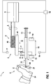
- FIG. 1 an active accelerator pedal 1 according to a first preferred embodiment of the invention described in detail.
- the active accelerator pedal 1 comprises a pedal unit 2 and an actuator unit 3.
- the delimitation between the pedal unit 2 and the actuator unit 3 is defined by a first stop 6 of the pedal unit and a second stop 7 of the actuator unit.
- the pedal unit 2 comprises a pedal 20 which can be actuated by means of a foot 24, for example. However, the pedal can also be operated completely different, for example with one hand or by a robot that acts as a "driver" and has sensors for counter-force determination.
- the pedal 20 is pivotable about a pivot axis 21. In this embodiment, a standing pedal is shown, but it can also be used a hanging pedal.
- the pedal 20 is connected via a linkage arrangement 9 with a first and second restoring element 11, 12 (designed to be redundant for safety reasons).
- a maximum pedal travel 15 is defined between an idle stop 13 and a full load stop 14 (see FIG FIG. 1 ).
- a first displacement sensor 16 detects a position of the pedal 20 via a travel path of the linkage arrangement 9.
- the actuator unit 3 comprises an electric drive 5 and a worm gear 4.
- the worm gear is designed in one stage and has a predetermined self-locking.
- the worm gear 4 comprises a Worm 40 and a driven screw element 41, which in FIG. 1 only schematically shown as a rack.
- a second stop 7 is arranged on the driven screw element 41.
- the first stop 6 is arranged on the linkage arrangement 9.
- a second displacement sensor 17 determines a position of the screw element 41.
- a driver operates with his foot 24, the pedal 20, so that depending on the pedal travel or the pedal position, which is detected by the first displacement sensor 16, a control unit 10 controls a drive of the vehicle.
- the actuator unit 3 is in a non-activated state, completely withdrawn, so that the first stop 6 of the pedal unit 2 can not come into contact with the second stop 7 of the actuator unit 3.
- the electric drive 5 is actuated via the control unit 10 (arrow A), so that the second stop 7 is moved via the worm gear 4 in the direction of arrow B.
- a counter force is generated, which the driver consciously perceives on the pedal 20.
- an elastomer element 8 is provided between the first stop 6 and the second stop 7.
- the generated counterforce is for example in a range of 10 to 15 N.
- the actuator unit 3 acts only in the direction of the arrow B, so that the actuator unit can not accelerate, but the pedal 20 can apply only in the direction of the idle position with a force.
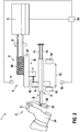
- FIG. 2 shows an active accelerator pedal 1 according to a second embodiment of the invention.
- the second embodiment essentially corresponds to the first embodiment, wherein, in contrast to the first embodiment, a coupling spring 18 between the first stop 6 and the second stop 7 is arranged.
- the coupling spring is a linear compression spring. Since the pedal unit 2 and the actuator unit 3 move independently and the respective positions are detected by means of the first displacement sensor 16 and the second displacement sensor 17, depending on the spring characteristic, a degree of tension of the coupling spring 18 is the resulting counterforce a driver also feels on the pedal 20. Since the positions are determined by means of the displacement sensors, it is thus possible to set the desired counterforce by the pedal position or the actuator position. As a result, the force setting of the counterforce can be attributed to a pure position control.
- the coupling spring 18 also additionally causes a damping of vibrations or the like, which could cause an unpleasant feeling for the driver on the pedal 20.
- the third embodiment mainly corresponds to the second embodiment, wherein again a coupling spring 18 is provided between the pedal unit 2 and the actuator unit 3.
- the coupling spring 18 is formed as a cylindrical torsion spring.
- a worm element 41 designed as a worm wheel is arranged coaxially to a pivot axis 21 of the pedal 20 ( FIG. 4 ).
- the screw element 41 is completely arranged in a housing 22 of the pedal unit 2.
- this embodiment additionally has a free path 50.
- the free path 50 ensures that the actuator unit 3 must first be actuated over a predetermined distance until a counterforce against a pedal movement can be generated. Only when a spring end 19 with a stop 7 on the screw element 41 (see FIG. 4 ) comes into contact, the counterforce is generated by the actuator unit 3.
- this embodiment of the invention is particularly compact. Also the snail 40 of the Worm gear 4 is arranged completely in the housing 22 of the pedal unit 2.
- FIGS. 5 and 6 show an active accelerator pedal 1 according to a fourth embodiment of the invention.
- a free path 50 between the pedal unit 2 and the actuator unit 3 is provided in the housing 22 of the pedal unit 2.
- a window 23 is provided in the housing 22 of the pedal unit 2.
- the window 23 serves to ensure that the worm 40, which protrudes partially into the window 23, can mesh with the worm element 41 designed as a worm wheel.
- a particularly compact housing 22 of the pedal unit 2 is provided.
- the pedal unit 2 can be easily adapted to different vehicle manufacturers by simply providing another housing with different position of the window 23 and correspondingly the electric drive 5 is positioned.
Landscapes
- Engineering & Computer Science (AREA)
- Mechanical Engineering (AREA)
- General Engineering & Computer Science (AREA)
- Chemical & Material Sciences (AREA)
- Combustion & Propulsion (AREA)
- Physics & Mathematics (AREA)
- General Physics & Mathematics (AREA)
- Automation & Control Theory (AREA)
- Transportation (AREA)
- Auxiliary Drives, Propulsion Controls, And Safety Devices (AREA)
Description
- Die vorliegende Erfindung betrifft ein aktives Fahrpedal eines Fahrzeugs mit einem Schneckengetriebe.
- Um Fahrern haptische Rückmeldungen über Fahrzeugzustände und Zustandsänderungen zu geben, zum Hinweis auf Gefahren oder zum Hinweis auf ein verbrauchsoptimiertes Fahren, können Pedale des Fahrzeugs verwendet werden. Die Rückmeldungen können beispielsweise als Gegenkraft am Pedal aufgebracht werden und abhängig von einer Situation verschiedene Ausgestaltungsformen, z.B. pulsierend oder vibrierend oder als Kraftschwelle, annehmen. Eine auf das Pedal auszuübende Gegenkraft liegt dabei im Bereich von 10 bis 15 N, wobei in bestimmten Situationen die Gegenkraft auch dauerhaft aufzubringen ist. Aus der
DE 102011054655 A1 ist beispielsweise ein aktives Fahrpedal bekannt, bei dem die Gegenkraft mittels eines Elektromotors aufgebracht wird und über ein schräg verzahntes Getriebe auf das Pedal übertragen wird. Dieses aktive Fahrpedal nimmt jedoch durch diese Ausgestaltung einen sehr großen Bauraum ein. Insbesondere im Fußraum eines Fahrzeugs ist Bauraum jedoch begrenzt und sollte möglichst effektiv eingesetzt werden. - Aus der
KR 101 406 489 B1 - Aus der
US 2011 / 0 260 557 A1 ist ein Aktuator für ein aktives Fahrpedal bekannt. - Aus der
US 2012 / 0 304 799 A1 ist eine aktive ECO-Pedalvorrichtung bekannt. - Das erfindungsgemäße aktive Fahrpedal eines Fahrzeugs mit den Merkmalen des Anspruchs 1 weist demgegenüber den Vorteil auf, dass nur ein geringer Bauraum notwendig ist und das Fahrpedal sehr einfach und kostengünstig aufgebaut ist.
- Auch kann erfindungsgemäß eine hohe Verfügbarkeit der aktiven Fahrpedalfunktionen sichergestellt werden. Dies wird erfindungsgemäß dadurch erreicht, dass das aktive Fahrzeugfahrpedal eine Pedaleinheit und eine Aktuatoreinheit umfasst. Die Pedaleinheit weist an einer Schwenkachse ein schwenkbar angeordnetes Pedal auf. Die Aktuatoreinheit umfasst einen elektrischen Antrieb, insbesondere einen elektronisch kommutierten Gleichstrommotor, und ein Schneckengetriebe mit einer Schnecke und einem angetriebenen Schneckenelement. Das Schneckengetriebe ist dabei zwischen dem elektrischen Antrieb und der Pedaleinheit angeordnet. Die Aktuatoreinheit ist ferner eingerichtet, einer auf das Pedal (z.B. durch eine Person ausgeübten) Pedalkraft eine Gegenkraft entgegenzusetzen. Somit kann dem Fahrer eine haptische Rückmeldung über das Pedal gegeben werden, beispielsweise für ein kraftstoffarmes Fahren oder eine Schwelle bei einem Hybridfahrzeug, an welcher vom elektrischen Antrieb auf einen Verbrennungsmotor umgeschaltet wird. Das Schneckengetriebe weist ferner den Vorteil einer gewissen Selbsthemmung auf, so dass Positionen der Aktuatoreinheit zur Erzeugung der Gegenkraft bei nur geringer Stromaufnahme gehalten werden.
- Die Unteransprüche zeigen bevorzugte Weiterbildungen der Erfindung.
- Vorzugsweise ist das Schneckengetriebe einstufig mit genau einer Schnecke und genau einem angetriebenen Schneckenelement, insbesondere einem Schneckenrad, ausgebildet. Hierdurch kann ein geringer Bauraum sichergestellt werden. Durch Anpassungen des Schneckengetriebes an die jeweiligen Gegebenheiten können somit einstufige Schneckengetriebe verwendet werden. Es ist auch möglich, ein zweistufiges oder mehrstufiges Schneckengetriebe vorzusehen, wobei eine Selbsthemmung des Schneckengetriebes mit zunehmenden Stufen stärker wird.
- Eine noch bessere Kompaktheit lässt sich erreichen, wenn eine Schwenkachse des Pedals und eine Mittelachse eines Schneckenrads zusammenfallen. Insbesondere kann bevorzugt das Schneckenrad auf eine Schwenkachse des Pedals aufgesteckt werden, so dass eine gute Integration des Schneckengetriebes in die Pedaleinheit möglich ist.
- Erfindungsgemäß weist die Pedaleinheit einen ersten Anschlag und die Aktuatoreinheit einen zweiten Anschlag auf. Die beiden Anschläge sind dabei vorgesehen, um eine von der Aktuatoreinheit aufgebrachte Gegenkraft auf die Pedaleinheit zu übertragen. Hierbei kann eine einfache und robuste Kraftübertragung ermöglicht werden. Besonders bevorzugt sind dabei an einem oder an beiden Anschlägen ein elastisches Element zur Dämpfung vorgesehen.
- Gemäß einer weiteren bevorzugten Ausgestaltung der Erfindung umfasst das aktive Fahrpedal ferner ein Federelement, welches in Wirkverbindung zwischen dem Schneckengetriebe und dem Pedal angeordnet ist. Das Federelement kann dabei eine zusätzliche Kraft aufbringen, welche sich mit der von der Aktuatoreinheit aufgebrachten Kraft zur gewünschten Gegenkraft addiert. Das Federelement ist bevorzugt eine Druckfeder oder alternativ eine Torsionsfeder. Ein weiterer Vorteil des Federelements liegt darin, dass das Federelement Schwingungen aufnehmen kann und somit dämpfende Eigenschaften aufweist, so dass ein Fahrer am Pedal keine ungewünschten Vibrationen oder dergleichen wahrnimmt.
- Weiter bevorzugt umfasst das aktive Fahrpedal ferner einen ersten und einen zweiten Wegsensor. Der erste Wegsensor bestimmt dabei eine Position eines mit dem Schneckengetriebe verbundenen bewegbaren Bauteils der Aktuatoreinheit. Der zweite Wegsensor bestimmt eine Position des Pedals der Pedaleinheit. Bei Verwendung des Federelements zwischen der Pedaleinheit und der Aktuatoreinheit ist es somit möglich, über eine Differenz zwischen einer Pedalposition und einer Aktorposition die gewünschte Gegenkraft am Pedal einzustellen, da die Positionen die von dem Federelement aufgebrachte Gegenkraft definieren. Somit kann die Krafteinstellung bzw. Kraftregelung auf eine reine Positionsregelung zurückgeführt werden, so dass die Steuereinheit sehr einfach und kostengünstig aufgebaut werden kann.
- Gemäß einer weiteren bevorzugten Ausgestaltung der Erfindung ist zwischen dem Schneckengetriebe und der Pedaleinheit ein Freiweg vorhanden, wobei erst nach Zurücklegen des Freiwegs die erzeugte Gegenkraft der Pedaleinheit entgegensetzbar ist. Somit kann die Aktuatoreinheit zuerst betrieben werden, ohne dass zunächst eine Gegenkraft auf das Pedal erzeugt wird. Erst nach Zurücklegen des vorbestimmten Freiweges kommt dann die Erzeugung der Gegenkraft gegenüber dem Pedal zustande. Hierdurch können gewünschte Verzögerungen bei der Erzeugung der Gegenkraft einfach realisiert werden.
- Weiter bevorzugt ist das angetriebene Schneckenelement in einem Gehäuse der Pedaleinheit angeordnet. Dadurch kann ein besonders kompakter Aufbau erreicht werden. Das Gehäuse weist vorzugsweise ein Fenster auf, durch welches die Schnecke hindurchgreift und mit dem Schneckenelement kämmt. Hierdurch kann die Kompaktheit des aktiven Fahrpedals weiter erhöht werden.
- Weiter bevorzugt weist das Schneckengetriebe ein Schneckenrad mit einer Innenverzahnung auf, wobei die Schnecke im Inneren des Schneckenrads angeordnet ist. Auch hierdurch kann eine weitere Kompaktheit erreicht werden. Ebenfalls weiter bevorzugt weist das Schneckenrad eine Außenverzahnung auf. Hierbei kann die Schnecke dann entlang des Umfangs des Außenrads an beliebiger Position positioniert werden, so dass eine höchste Flexibilität hinsichtlich der Anordnung der Schnecke und des mit der Schnecke verbundenen elektrischen Antriebs erreicht wird.
- Weiter alternativ weist das Schneckengetriebe ein Schneckenelement auf, welches eine in Axialrichtung gerichtete Schneckenverzahnung aufweist, die mit der Schnecke kämmt. Auch hierdurch werden weitere Alternativen hinsichtlich einer möglichen Anordnung von Bauteilen des aktiven Fahrpedals erhalten.
- Ferner umfasst das Fahrpedal eine Steuereinheit zur Betätigung der Aktuatoreinheit, wobei die Aktuatoreinheit eingerichtet ist, basierend auf Signalen der Steuereinheit, einer auf das Pedal ausgeübten Pedalkraft eine Gegenkraft entgegenzusetzen.
- Nachfolgend werden bevorzugte Ausführungsbeispiele der Erfindung unter Bezugnahme auf die begleitende Zeichnung im Detail beschrieben. Gleiche bzw. funktional gleiche Teile sind jeweils mit den gleichen Bezugszeichen bezeichnet. In der Zeichnung ist:
- Figur 1
- eine schematische Ansicht eines aktiven Fahrpedals gemäß einem ersten Ausführungsbeispiel der Erfindung,
- Figur 2
- eine schematische Ansicht eines aktiven Fahrpedals gemäß einem zweiten Ausführungsbeispiel der Erfindung,
- Figur 3
- eine Explosionsdarstellung eines aktiven Fahrpedals gemäß einem dritten Ausführungsbeispiel der Erfindung,
- Figur 4
- eine Schnittansicht des aktiven Fahrpedals von
Figur 3 , - Figur 5
- eine schematische Ansicht eines aktiven Fahrpedals gemäß einem vierten Ausführungsbeispiel der Erfindung und
- Figur 6
- eine schematische Draufsicht auf das aktive Fahrpedal von
Figur 5 . - Nachfolgend wird unter Bezugnahme auf
Figur 1 ein aktives Fahrpedal 1 gemäß einem ersten bevorzugten Ausführungsbeispiel der Erfindung im Detail beschrieben. - Wie aus
Figur 1 ersichtlich ist, umfasst das aktive Fahrpedal 1 eine Pedaleinheit 2 und eine Aktuatoreinheit 3. Die Abgrenzung zwischen der Pedaleinheit 2 und der Aktuatoreinheit 3 wird durch einen ersten Anschlag 6 der Pedaleinheit und einen zweiten Anschlag 7 der Aktuatoreinheit definiert. - Die Pedaleinheit 2 umfasst ein Pedal 20, welches z.B. mittels eines Fußes 24 betätigbar ist. Das Pedal kann jedoch auch vollkommen anders betätigt werden, z.B. mit einer Hand oder durch einen Roboter, der als "Fahrer" fungiert und Sensoren zur Gegenkraftermittlung aufweist. Das Pedal 20 ist um eine Schwenkachse 21 schwenkbar. In diesem Ausführungsbeispiel ist ein stehendes Pedal dargestellt, es kann jedoch auch ein hängendes Pedal verwendet werden. Das Pedal 20 ist über eine Gestängeanordnung 9 mit einem ersten und zweiten Rückstellelement 11, 12 (aus Sicherheitsgründen redundant ausgeführt) verbunden. Ein maximaler Pedalweg 15 ist zwischen einem Leerlaufanschlag 13 und einem Volllastanschlag 14 definiert (vergleiche
Figur 1 ). - Ein erster Wegsensor 16 erfasst eine Position des Pedals 20 über einen Verfahrweg der Gestängeanordnung 9.
- Die Aktuatoreinheit 3 umfasst einen elektrischen Antrieb 5 und ein Schneckengetriebe 4. Das Schneckengetriebe ist einstufig ausgebildet und weist eine vorbestimmte Selbsthemmung auf. Das Schneckengetriebe 4 umfasst eine Schnecke 40 und ein angetriebenes Schneckenelement 41, welches in
Figur 1 nur schematisch als Zahnstange dargestellt ist. Am angetriebenen Schneckenelement 41 ist ein zweiter Anschlag 7 angeordnet. Der erste Anschlag 6 ist an der Gestängeanordnung 9 angeordnet. Ein zweiter Wegsensor 17 bestimmt eine Position des Schneckenelements 41. - Im normalen Betrieb betätigt ein Fahrer mit seinem Fuß 24 das Pedal 20, so dass abhängig vom Pedalweg bzw. der Pedalstellung, welche mittels des ersten Wegsensors 16 erfassbar ist, eine Steuereinheit 10 einen Antrieb des Fahrzeugs steuert. Die Aktuatoreinheit 3 befindet sich dabei in einem nicht aktivierten Zustand, vollständig zurückgezogen, so dass der erste Anschlag 6 der Pedaleinheit 2 nicht mit dem zweiten Anschlag 7 der Aktuatoreinheit 3 in Kontakt kommen kann.
- Wenn nun ein aktives Fahrpedal gewünscht wird, beispielsweise in einer Kraftstoffsparstellung für das Fahrzeug, wird über die Steuereinheit 10 der elektrische Antrieb 5 betätigt (Pfeil A), so dass der zweite Anschlag 7 über das Schneckengetriebe 4 in Richtung des Pfeils B bewegt wird. Sobald der erste Anschlag 6 mit dem zweiten Anschlag 7 in Kontakt kommt, wird eine Gegenkraft erzeugt, welche der Fahrer bewusst am Pedal 20 wahrnimmt. Zur Dämpfung des Kontaktes ist zwischen dem ersten Anschlag 6 und dem zweiten Anschlag 7 ein Elastomerelement 8 vorgesehen. Die erzeugte Gegenkraft liegt beispielsweise in einem Bereich von 10 bis 15 N.
- Der Fahrer kann dann das Pedal 20 nur so weit durchdrücken (Pfeil C), bis die Gestängeanordnung 9 so weit verfahren ist (Pfeil D), so dass der Anschlag 6 mit dem Anschlag 7 in Kontakt kommt. Wenn der Fahrer stärker auf das Pedal drückt, wird die Selbsthemmung des Schneckengetriebes 4 überwunden, so dass der Anschlag 6 das Schneckenelement 41 in Richtung entgegen der Bewegungsrichtung B und entgegen der aufgebrachten Gegenkraft bewegt.
- Es sei angemerkt, dass die Aktuatoreinheit 3 nur in die Richtung des Pfeils B wirkt, so dass die Aktuatoreinheit nicht beschleunigend wirken kann, sondern das Pedal 20 nur in Richtung der Leerlaufposition mit einer Kraft beaufschlagen kann.
-
Figur 2 zeigt ein aktives Fahrpedal 1 gemäß einem zweiten Ausführungsbeispiel der Erfindung. Das zweite Ausführungsbeispiel entspricht im Wesentlichen dem ersten Ausführungsbeispiel, wobei im Unterschied zum ersten Ausführungsbeispiel eine Koppelfeder 18 zwischen dem ersten Anschlag 6 und dem zweiten Anschlag 7 angeordnet ist. In diesem Ausführungsbeispiel ist die Koppelfeder eine lineare Druckfeder. Da sich die Pedaleinheit 2 und die Aktuatoreinheit 3 unabhängig voneinander bewegen und die jeweiligen Positionen mittels des ersten Wegsensors 16 bzw. des zweiten Wegsensors 17 erfasst werden, ist, abhängig von der Federkennlinie, ein Maß einer Verspannung der Koppelfeder 18 die sich ergebende Gegenkraft, die ein Fahrer zusätzlich am Pedal 20 spürt. Da die Positionen mittels der Wegsensoren bestimmt werden, ist es somit möglich, die gewünschte Gegenkraft durch die Pedalposition bzw. die Aktuatorposition einzustellen. Hierdurch kann die Krafteinstellung der Gegenkraft auf eine reine Positionsregelung zurückgeführt werden. Die Koppelfeder 18 bewirkt auch zusätzlich noch ein Dämpfen von Schwingungen oder dergleichen, welche am Pedal 20 ein unangenehmes Gefühl für den Fahrer bewirken könnten. - Nachfolgend wird unter Bezugnahme auf die
Figuren 3 und4 ein aktives Fahrpedal gemäß einem dritten Ausführungsbeispiel der Erfindung im Detail beschrieben. - Das dritte Ausführungsbeispiel entspricht hauptsächlich dem zweiten Ausführungsbeispiel, wobei wiederum eine Koppelfeder 18 zwischen der Pedaleinheit 2 und der Aktuatoreinheit 3 vorgesehen ist. Im dritten Ausführungsbeispiel ist die Koppelfeder 18 jedoch als zylindrische Torsionsfeder ausgebildet. Weiterhin ist ein als Schneckenrad ausgebildetes Schneckenelement 41 koaxial zu einer Schwenkachse 21 des Pedals 20 angeordnet (
Figur 4 ). Das Schneckenelement 41 ist dabei vollständig in einem Gehäuse 22 der Pedaleinheit 2 angeordnet. - Wie weiterhin aus
Figur 4 ersichtlich ist, weist dieses Ausführungsbeispiel zusätzlich einen Freiweg 50 auf. Der Freiweg 50 stellt sicher, dass die Aktuatoreinheit 3 zuerst über eine vorbestimmte Wegstrecke betätigt werden muss, bis eine Gegenkraft gegen eine Pedalbewegung erzeugbar ist. Erst wenn ein Federende 19 mit einem Anschlag 7 am Schneckenelement 41 (vergleicheFigur 4 ) in Kontakt kommt, wird die Gegenkraft durch die Aktuatoreinheit 3 erzeugt. Wie aus denFiguren 3 und4 ersichtlich ist, ist diese erfindungsgemäße Ausgestaltung besonders kompakt aufgebaut. Auch die Schnecke 40 des Schneckengetriebes 4 ist vollständig im Gehäuse 22 der Pedaleinheit 2 angeordnet. - Die
Figuren 5 und 6 zeigen ein aktives Fahrpedal 1 gemäß einem vierten Ausführungsbeispiel der Erfindung. Bei diesem Ausführungsbeispiel ist wiederum ein Freiweg 50 zwischen der Pedaleinheit 2 und der Aktuatoreinheit 3 vorgesehen. Ferner ist im Gehäuse 22 der Pedaleinheit 2 ein Fenster 23 vorgesehen. Das Fenster 23 dient dabei dazu, dass die Schnecke 40, welche teilweise in das Fenster 23 vorsteht, mit dem als Schneckenrad ausgebildeten Schneckenelement 41 kämmen kann. Hierdurch wird ein besonders kompaktes Gehäuse 22 der Pedaleinheit 2 bereitgestellt. Weiterhin kann durch die Lösung mit dem Fenster 23 im Gehäuse 22 die Pedaleinheit 2 jeweils auf unterschiedliche Fahrzeughersteller einfach angepasst werden, indem einfach ein anderes Gehäuse mit anderer Position des Fensters 23 bereitgestellt wird und entsprechend der elektrische Antrieb 5 positioniert wird.
Claims (11)
- Aktives Fahrpedal eines Fahrzeugs, umfassend- eine Pedaleinheit (2) mit einem an einer Schwenkachse (21) schwenkbar angeordneten Pedal (20), und- eine Aktuatoreinheit (3) mit einem elektrischen Antrieb (5) und einem Schneckengetriebe (4) mit einer Schnecke (40) und einem angetriebenen Schneckenelement (41),- wobei das Schneckengetriebe (4) zwischen dem elektrischen Antrieb (5) und der Pedaleinheit (2) angeordnet ist, und- wobei die Aktuatoreinheit (3) eingerichtet ist, einer auf das Pedal ausgeübten Pedalkraft eine Gegenkraft entgegenzusetzen,dadurch gekennzeichnet, dass
die Pedaleinheit (2) einen ersten Anschlag (6) und die Aktuatoreinheit (3) einen zweiten Anschlag (7) aufweist, um die von der Aktuatoreinheit (3) aufgebrachte Gegenkraft auf die Pedaleinheit (2) zu übertragen. - Fahrpedal nach Anspruch 1, dadurch gekennzeichnet, dass das Schneckengetriebe (4) einstufig mit genau einer Schnecke (40) und genau einem Schneckenrad ausgebildet ist.
- Fahrpedal nach einem der vorhergehenden Ansprüche, dadurch gekennzeichnet, dass das Schneckenelement (41) ein Schneckenrad ist.
- Fahrpedal nach Anspruch 3, dadurch gekennzeichnet, dass die Schwenkachse (21) des Pedals (20) und eine Mittelachse des Schneckenrads zusammenfallen.
- Fahrpedal nach einem der vorhergehenden Ansprüche, ferner umfassend ein Federelement (18), welches in Wirkverbindung zwischen dem Schneckengetriebe (4) und dem Pedal (20) angeordnet ist.
- Fahrpedal nach Anspruch 5, dadurch gekennzeichnet, dass das Federelement (18) eine Druckfeder oder eine Torsionsfeder ist.
- Fahrpedal nach einem der vorhergehenden Ansprüche, ferner umfassend einen ersten Wegsensor (16) und einen zweiten Wegsensor (17), wobei der erste Wegsensor (16) eine Position eines bewegbaren Bauteils, insbesondere des angetriebenen Schneckenelements (41), der Aktuatoreinheit bestimmt und der zweite Wegsensor (17) eine Position des Pedals (20) bestimmt.
- Fahrpedal nach einem der vorhergehenden Ansprüche, dadurch gekennzeichnet, dass zwischen dem Schneckengetriebe (4) und der Pedaleinheit (2) ein Freiweg (50) vorhanden ist, wobei nach Zurücklegen des Freiwegs (50) die Gegenkraft der Aktuatoreinheit (3) der Pedaleinheit (2) entgegensetzbar ist.
- Fahrpedal nach einem der vorhergehenden Ansprüche, dadurch gekennzeichnet, dass das Schneckenelement (41) in einem Gehäuse (22) der Pedaleinheit (2) angeordnet ist und das Gehäuse (22) ein Fenster (23) aufweist, durch welches die Schnecke (40) in das Schneckenelement (41) eingreift.
- Fahrpedal nach Anspruch 6 und Anspruch 8, dadurch gekennzeichnet, dass der Freiweg (50) zwischen einem Federende (19) des Federelements (18) und einem Anschlag (42) am Schneckengetriebe (4) vorhanden ist.
- Fahrpedal nach einem der vorhergehenden Ansprüche, ferner umfassend eine Steuereinheit (10) zur Betätigung der Aktuatoreinheit (3), wobei die Aktuatoreinheit (3) eingerichtet ist, basierend auf Signalen der Steuereinheit (10) einer auf das Pedal (20) ausgeübten Pedalkraft eine Gegenkraft entgegenzusetzen.
Applications Claiming Priority (2)
| Application Number | Priority Date | Filing Date | Title |
|---|---|---|---|
| DE102014217319.1A DE102014217319A1 (de) | 2014-08-29 | 2014-08-29 | Aktives Fahrpedal mit Schneckengetriebe |
| PCT/EP2015/065567 WO2016030066A1 (de) | 2014-08-29 | 2015-07-08 | Aktives fahrpedal mit schneckengetriebe |
Publications (2)
| Publication Number | Publication Date |
|---|---|
| EP3186103A1 EP3186103A1 (de) | 2017-07-05 |
| EP3186103B1 true EP3186103B1 (de) | 2019-09-11 |
Family
ID=53546591
Family Applications (1)
| Application Number | Title | Priority Date | Filing Date |
|---|---|---|---|
| EP15738017.1A Active EP3186103B1 (de) | 2014-08-29 | 2015-07-08 | Aktives fahrpedal mit schneckengetriebe |
Country Status (5)
| Country | Link |
|---|---|
| US (1) | US20170217312A1 (de) |
| EP (1) | EP3186103B1 (de) |
| KR (1) | KR20170045231A (de) |
| DE (1) | DE102014217319A1 (de) |
| WO (1) | WO2016030066A1 (de) |
Families Citing this family (14)
| Publication number | Priority date | Publication date | Assignee | Title |
|---|---|---|---|---|
| DE102015204236A1 (de) * | 2015-03-10 | 2016-09-15 | Continental Automotive Gmbh | Pedal mit adaptiver Kraftrückkopplung und Schneckenantrieb |
| EP3229098B1 (de) * | 2016-04-06 | 2024-07-17 | Ratier-Figeac SAS | Vorrichtung mit asymmetrischer rückkopplung |
| EP3770718B1 (de) * | 2018-03-19 | 2022-12-28 | Alps Alpine Co., Ltd. | Eingabevorrichtung |
| CN111806228B (zh) * | 2020-08-04 | 2023-06-02 | 刘志光 | 防误踩油门加油转换制动的装置及方法 |
| IT202100001535A1 (it) * | 2021-01-27 | 2022-07-27 | Bitron Spa | Pedale acceleratore, in particolare per un autoveicolo |
| JP7639616B2 (ja) * | 2021-08-25 | 2025-03-05 | 株式会社デンソー | アクセルペダルシステム |
| JP7639617B2 (ja) * | 2021-08-25 | 2025-03-05 | 株式会社デンソー | アクセルペダルシステム |
| JP7629372B2 (ja) * | 2021-08-25 | 2025-02-13 | 株式会社デンソー | アクセルペダルシステム |
| JP2023031746A (ja) * | 2021-08-25 | 2023-03-09 | 株式会社デンソー | アクセルペダルシステム |
| JP7636298B2 (ja) * | 2021-08-25 | 2025-02-26 | 株式会社デンソー | アクセルペダルシステム |
| JP7639615B2 (ja) * | 2021-08-25 | 2025-03-05 | 株式会社デンソー | アクセルペダルシステム |
| JP7561103B2 (ja) * | 2021-08-25 | 2024-10-03 | 株式会社デンソー | アクセルペダルシステム |
| US11565667B1 (en) * | 2022-02-01 | 2023-01-31 | Ford Global Technologies, Llc | Automatic brake pedal control |
| FI131095B1 (en) * | 2022-09-08 | 2024-09-26 | Granite Devices Oy | Game pedal and method of controlling the game pedal |
Family Cites Families (4)
| Publication number | Priority date | Publication date | Assignee | Title |
|---|---|---|---|---|
| KR101145533B1 (ko) * | 2010-04-23 | 2012-05-15 | 주식회사 동희산업 | 능동형 가속페달의 엑츄에이터 장치 |
| KR101223069B1 (ko) * | 2011-05-30 | 2013-01-17 | (주) 디에이치홀딩스 | 능동타입 에코페달장치 |
| DE102011054655A1 (de) | 2011-10-20 | 2013-04-25 | Ab Elektronik Gmbh | Pedaleinheit für ein KFZ |
| KR101406489B1 (ko) * | 2013-04-23 | 2014-06-12 | 기아자동차주식회사 | 가속페달 장치의 답력 능동 조절방법 |
-
2014
- 2014-08-29 DE DE102014217319.1A patent/DE102014217319A1/de not_active Withdrawn
-
2015
- 2015-07-08 WO PCT/EP2015/065567 patent/WO2016030066A1/de not_active Ceased
- 2015-07-08 EP EP15738017.1A patent/EP3186103B1/de active Active
- 2015-07-08 KR KR1020177005496A patent/KR20170045231A/ko not_active Withdrawn
- 2015-07-08 US US15/501,564 patent/US20170217312A1/en not_active Abandoned
Non-Patent Citations (1)
| Title |
|---|
| None * |
Also Published As
| Publication number | Publication date |
|---|---|
| WO2016030066A1 (de) | 2016-03-03 |
| US20170217312A1 (en) | 2017-08-03 |
| DE102014217319A1 (de) | 2016-03-03 |
| EP3186103A1 (de) | 2017-07-05 |
| KR20170045231A (ko) | 2017-04-26 |
Similar Documents
| Publication | Publication Date | Title |
|---|---|---|
| WO2016030066A1 (de) | Aktives fahrpedal mit schneckengetriebe | |
| EP3119661B1 (de) | Lenksäule für ein kraftfahrzeug, gewindestange und spindelmutter | |
| EP3380390A1 (de) | Feedbackaktuator für eine steer-by-wire-lenkung | |
| EP3186104B1 (de) | Aktives fahrpedal mit freiweg | |
| EP2900513A1 (de) | Kupplungspedaleinrichtung | |
| DE60302011T2 (de) | Gaspedal mit integrierter Rückstellkraftkontrolle | |
| EP3180227A1 (de) | Fahrzeug-lenkung | |
| EP2896539A2 (de) | System zur Pedalkraftsimulation, insbesondere für ein Kupplungsbetätigungssystem | |
| DE102014222805B4 (de) | Rückstellmomenterzeugungsvorrichtungen | |
| WO2011101095A1 (de) | Kraftfahrzeug | |
| DE102010063409A1 (de) | Fahrpedal mit einstellbarer Betätigungscharakteristik | |
| DE102011052504A1 (de) | Gaspedal für Fahrzeug | |
| DE112021001676T5 (de) | Beschleunigervorrichtung | |
| DE4422232A1 (de) | Stellwertgeber | |
| EP2785555B1 (de) | Pedalwertgeberanordnung | |
| DE102010063053A1 (de) | Pedalwertgeberanordnung | |
| EP3388276B1 (de) | Bedienanordnung zum bedienen von zumindest einem elektrischen gerät mit einem kraftsensor, fahrerassistenzsystem, kraftfahrzeug sowie verfahren zum bedienen einer bedienanordnung | |
| DE102014214380B3 (de) | Verfahren zur Steuerung und/oder Regelung der Leistung eines Motors | |
| EP3137784B1 (de) | Vorrichtung zur kraftsimulation an einem betätigungselement eines fahrzeuges, vorzugsweise ein pedalsimulator, und eine einrichtung zur betätigung eines elektrischen kupplungssystems | |
| WO2016131848A1 (de) | Schaltbedienanordnung | |
| DE102008060114A1 (de) | Multifunktions-Bedienelement | |
| BE1029981B1 (de) | Lenksystem für ein Kraftfahrzeug | |
| EP2505980A2 (de) | Verfahren und Vorrichtung zur Bestimmung eines Drehmoments | |
| EP2694354B1 (de) | Vorrichtung zur gabe eines haptisch erfahrbaren signals auf eine lenkwelle eines fahrzeugs | |
| DE102009058967A1 (de) | Fahrpedal |
Legal Events
| Date | Code | Title | Description |
|---|---|---|---|
| STAA | Information on the status of an ep patent application or granted ep patent |
Free format text: STATUS: THE INTERNATIONAL PUBLICATION HAS BEEN MADE |
|
| PUAI | Public reference made under article 153(3) epc to a published international application that has entered the european phase |
Free format text: ORIGINAL CODE: 0009012 |
|
| STAA | Information on the status of an ep patent application or granted ep patent |
Free format text: STATUS: REQUEST FOR EXAMINATION WAS MADE |
|
| 17P | Request for examination filed |
Effective date: 20170329 |
|
| AK | Designated contracting states |
Kind code of ref document: A1 Designated state(s): AL AT BE BG CH CY CZ DE DK EE ES FI FR GB GR HR HU IE IS IT LI LT LU LV MC MK MT NL NO PL PT RO RS SE SI SK SM TR |
|
| AX | Request for extension of the european patent |
Extension state: BA ME |
|
| DAV | Request for validation of the european patent (deleted) | ||
| DAX | Request for extension of the european patent (deleted) | ||
| GRAP | Despatch of communication of intention to grant a patent |
Free format text: ORIGINAL CODE: EPIDOSNIGR1 |
|
| STAA | Information on the status of an ep patent application or granted ep patent |
Free format text: STATUS: GRANT OF PATENT IS INTENDED |
|
| INTG | Intention to grant announced |
Effective date: 20190514 |
|
| GRAS | Grant fee paid |
Free format text: ORIGINAL CODE: EPIDOSNIGR3 |
|
| GRAA | (expected) grant |
Free format text: ORIGINAL CODE: 0009210 |
|
| STAA | Information on the status of an ep patent application or granted ep patent |
Free format text: STATUS: THE PATENT HAS BEEN GRANTED |
|
| AK | Designated contracting states |
Kind code of ref document: B1 Designated state(s): AL AT BE BG CH CY CZ DE DK EE ES FI FR GB GR HR HU IE IS IT LI LT LU LV MC MK MT NL NO PL PT RO RS SE SI SK SM TR |
|
| REG | Reference to a national code |
Ref country code: GB Ref legal event code: FG4D Free format text: NOT ENGLISH |
|
| REG | Reference to a national code |
Ref country code: CH Ref legal event code: EP |
|
| REG | Reference to a national code |
Ref country code: AT Ref legal event code: REF Ref document number: 1177993 Country of ref document: AT Kind code of ref document: T Effective date: 20190915 |
|
| REG | Reference to a national code |
Ref country code: DE Ref legal event code: R096 Ref document number: 502015010332 Country of ref document: DE |
|
| REG | Reference to a national code |
Ref country code: IE Ref legal event code: FG4D Free format text: LANGUAGE OF EP DOCUMENT: GERMAN |
|
| REG | Reference to a national code |
Ref country code: NL Ref legal event code: MP Effective date: 20190911 |
|
| REG | Reference to a national code |
Ref country code: LT Ref legal event code: MG4D |
|
| PG25 | Lapsed in a contracting state [announced via postgrant information from national office to epo] |
Ref country code: LT Free format text: LAPSE BECAUSE OF FAILURE TO SUBMIT A TRANSLATION OF THE DESCRIPTION OR TO PAY THE FEE WITHIN THE PRESCRIBED TIME-LIMIT Effective date: 20190911 Ref country code: FI Free format text: LAPSE BECAUSE OF FAILURE TO SUBMIT A TRANSLATION OF THE DESCRIPTION OR TO PAY THE FEE WITHIN THE PRESCRIBED TIME-LIMIT Effective date: 20190911 Ref country code: SE Free format text: LAPSE BECAUSE OF FAILURE TO SUBMIT A TRANSLATION OF THE DESCRIPTION OR TO PAY THE FEE WITHIN THE PRESCRIBED TIME-LIMIT Effective date: 20190911 Ref country code: HR Free format text: LAPSE BECAUSE OF FAILURE TO SUBMIT A TRANSLATION OF THE DESCRIPTION OR TO PAY THE FEE WITHIN THE PRESCRIBED TIME-LIMIT Effective date: 20190911 Ref country code: NO Free format text: LAPSE BECAUSE OF FAILURE TO SUBMIT A TRANSLATION OF THE DESCRIPTION OR TO PAY THE FEE WITHIN THE PRESCRIBED TIME-LIMIT Effective date: 20191211 Ref country code: BG Free format text: LAPSE BECAUSE OF FAILURE TO SUBMIT A TRANSLATION OF THE DESCRIPTION OR TO PAY THE FEE WITHIN THE PRESCRIBED TIME-LIMIT Effective date: 20191211 |
|
| PG25 | Lapsed in a contracting state [announced via postgrant information from national office to epo] |
Ref country code: ES Free format text: LAPSE BECAUSE OF FAILURE TO SUBMIT A TRANSLATION OF THE DESCRIPTION OR TO PAY THE FEE WITHIN THE PRESCRIBED TIME-LIMIT Effective date: 20190911 Ref country code: AL Free format text: LAPSE BECAUSE OF FAILURE TO SUBMIT A TRANSLATION OF THE DESCRIPTION OR TO PAY THE FEE WITHIN THE PRESCRIBED TIME-LIMIT Effective date: 20190911 Ref country code: LV Free format text: LAPSE BECAUSE OF FAILURE TO SUBMIT A TRANSLATION OF THE DESCRIPTION OR TO PAY THE FEE WITHIN THE PRESCRIBED TIME-LIMIT Effective date: 20190911 Ref country code: GR Free format text: LAPSE BECAUSE OF FAILURE TO SUBMIT A TRANSLATION OF THE DESCRIPTION OR TO PAY THE FEE WITHIN THE PRESCRIBED TIME-LIMIT Effective date: 20191212 Ref country code: RS Free format text: LAPSE BECAUSE OF FAILURE TO SUBMIT A TRANSLATION OF THE DESCRIPTION OR TO PAY THE FEE WITHIN THE PRESCRIBED TIME-LIMIT Effective date: 20190911 |
|
| RAP2 | Party data changed (patent owner data changed or rights of a patent transferred) |
Owner name: ROBERT BOSCH GMBH |
|
| PG25 | Lapsed in a contracting state [announced via postgrant information from national office to epo] |
Ref country code: PL Free format text: LAPSE BECAUSE OF FAILURE TO SUBMIT A TRANSLATION OF THE DESCRIPTION OR TO PAY THE FEE WITHIN THE PRESCRIBED TIME-LIMIT Effective date: 20190911 Ref country code: EE Free format text: LAPSE BECAUSE OF FAILURE TO SUBMIT A TRANSLATION OF THE DESCRIPTION OR TO PAY THE FEE WITHIN THE PRESCRIBED TIME-LIMIT Effective date: 20190911 Ref country code: NL Free format text: LAPSE BECAUSE OF FAILURE TO SUBMIT A TRANSLATION OF THE DESCRIPTION OR TO PAY THE FEE WITHIN THE PRESCRIBED TIME-LIMIT Effective date: 20190911 Ref country code: RO Free format text: LAPSE BECAUSE OF FAILURE TO SUBMIT A TRANSLATION OF THE DESCRIPTION OR TO PAY THE FEE WITHIN THE PRESCRIBED TIME-LIMIT Effective date: 20190911 Ref country code: PT Free format text: LAPSE BECAUSE OF FAILURE TO SUBMIT A TRANSLATION OF THE DESCRIPTION OR TO PAY THE FEE WITHIN THE PRESCRIBED TIME-LIMIT Effective date: 20200113 Ref country code: IT Free format text: LAPSE BECAUSE OF FAILURE TO SUBMIT A TRANSLATION OF THE DESCRIPTION OR TO PAY THE FEE WITHIN THE PRESCRIBED TIME-LIMIT Effective date: 20190911 |
|
| PG25 | Lapsed in a contracting state [announced via postgrant information from national office to epo] |
Ref country code: SM Free format text: LAPSE BECAUSE OF FAILURE TO SUBMIT A TRANSLATION OF THE DESCRIPTION OR TO PAY THE FEE WITHIN THE PRESCRIBED TIME-LIMIT Effective date: 20190911 Ref country code: SK Free format text: LAPSE BECAUSE OF FAILURE TO SUBMIT A TRANSLATION OF THE DESCRIPTION OR TO PAY THE FEE WITHIN THE PRESCRIBED TIME-LIMIT Effective date: 20190911 Ref country code: IS Free format text: LAPSE BECAUSE OF FAILURE TO SUBMIT A TRANSLATION OF THE DESCRIPTION OR TO PAY THE FEE WITHIN THE PRESCRIBED TIME-LIMIT Effective date: 20200224 Ref country code: CZ Free format text: LAPSE BECAUSE OF FAILURE TO SUBMIT A TRANSLATION OF THE DESCRIPTION OR TO PAY THE FEE WITHIN THE PRESCRIBED TIME-LIMIT Effective date: 20190911 |
|
| REG | Reference to a national code |
Ref country code: DE Ref legal event code: R097 Ref document number: 502015010332 Country of ref document: DE |
|
| PLBE | No opposition filed within time limit |
Free format text: ORIGINAL CODE: 0009261 |
|
| STAA | Information on the status of an ep patent application or granted ep patent |
Free format text: STATUS: NO OPPOSITION FILED WITHIN TIME LIMIT |
|
| PG2D | Information on lapse in contracting state deleted |
Ref country code: IS |
|
| PG25 | Lapsed in a contracting state [announced via postgrant information from national office to epo] |
Ref country code: DK Free format text: LAPSE BECAUSE OF FAILURE TO SUBMIT A TRANSLATION OF THE DESCRIPTION OR TO PAY THE FEE WITHIN THE PRESCRIBED TIME-LIMIT Effective date: 20190911 Ref country code: IS Free format text: LAPSE BECAUSE OF FAILURE TO SUBMIT A TRANSLATION OF THE DESCRIPTION OR TO PAY THE FEE WITHIN THE PRESCRIBED TIME-LIMIT Effective date: 20200112 |
|
| 26N | No opposition filed |
Effective date: 20200615 |
|
| PG25 | Lapsed in a contracting state [announced via postgrant information from national office to epo] |
Ref country code: SI Free format text: LAPSE BECAUSE OF FAILURE TO SUBMIT A TRANSLATION OF THE DESCRIPTION OR TO PAY THE FEE WITHIN THE PRESCRIBED TIME-LIMIT Effective date: 20190911 |
|
| PG25 | Lapsed in a contracting state [announced via postgrant information from national office to epo] |
Ref country code: MC Free format text: LAPSE BECAUSE OF FAILURE TO SUBMIT A TRANSLATION OF THE DESCRIPTION OR TO PAY THE FEE WITHIN THE PRESCRIBED TIME-LIMIT Effective date: 20190911 |
|
| REG | Reference to a national code |
Ref country code: CH Ref legal event code: PL |
|
| GBPC | Gb: european patent ceased through non-payment of renewal fee |
Effective date: 20200708 |
|
| REG | Reference to a national code |
Ref country code: BE Ref legal event code: MM Effective date: 20200731 |
|
| PG25 | Lapsed in a contracting state [announced via postgrant information from national office to epo] |
Ref country code: CH Free format text: LAPSE BECAUSE OF NON-PAYMENT OF DUE FEES Effective date: 20200731 Ref country code: GB Free format text: LAPSE BECAUSE OF NON-PAYMENT OF DUE FEES Effective date: 20200708 Ref country code: LI Free format text: LAPSE BECAUSE OF NON-PAYMENT OF DUE FEES Effective date: 20200731 Ref country code: LU Free format text: LAPSE BECAUSE OF NON-PAYMENT OF DUE FEES Effective date: 20200708 |
|
| PG25 | Lapsed in a contracting state [announced via postgrant information from national office to epo] |
Ref country code: BE Free format text: LAPSE BECAUSE OF NON-PAYMENT OF DUE FEES Effective date: 20200731 |
|
| PG25 | Lapsed in a contracting state [announced via postgrant information from national office to epo] |
Ref country code: IE Free format text: LAPSE BECAUSE OF NON-PAYMENT OF DUE FEES Effective date: 20200708 |
|
| REG | Reference to a national code |
Ref country code: AT Ref legal event code: MM01 Ref document number: 1177993 Country of ref document: AT Kind code of ref document: T Effective date: 20200708 |
|
| PG25 | Lapsed in a contracting state [announced via postgrant information from national office to epo] |
Ref country code: AT Free format text: LAPSE BECAUSE OF NON-PAYMENT OF DUE FEES Effective date: 20200708 |
|
| PGFP | Annual fee paid to national office [announced via postgrant information from national office to epo] |
Ref country code: FR Payment date: 20210722 Year of fee payment: 7 |
|
| PGFP | Annual fee paid to national office [announced via postgrant information from national office to epo] |
Ref country code: DE Payment date: 20210924 Year of fee payment: 7 |
|
| PG25 | Lapsed in a contracting state [announced via postgrant information from national office to epo] |
Ref country code: TR Free format text: LAPSE BECAUSE OF FAILURE TO SUBMIT A TRANSLATION OF THE DESCRIPTION OR TO PAY THE FEE WITHIN THE PRESCRIBED TIME-LIMIT Effective date: 20190911 Ref country code: MT Free format text: LAPSE BECAUSE OF FAILURE TO SUBMIT A TRANSLATION OF THE DESCRIPTION OR TO PAY THE FEE WITHIN THE PRESCRIBED TIME-LIMIT Effective date: 20190911 Ref country code: CY Free format text: LAPSE BECAUSE OF FAILURE TO SUBMIT A TRANSLATION OF THE DESCRIPTION OR TO PAY THE FEE WITHIN THE PRESCRIBED TIME-LIMIT Effective date: 20190911 |
|
| PG25 | Lapsed in a contracting state [announced via postgrant information from national office to epo] |
Ref country code: MK Free format text: LAPSE BECAUSE OF FAILURE TO SUBMIT A TRANSLATION OF THE DESCRIPTION OR TO PAY THE FEE WITHIN THE PRESCRIBED TIME-LIMIT Effective date: 20190911 |
|
| REG | Reference to a national code |
Ref country code: DE Ref legal event code: R119 Ref document number: 502015010332 Country of ref document: DE |
|
| PG25 | Lapsed in a contracting state [announced via postgrant information from national office to epo] |
Ref country code: FR Free format text: LAPSE BECAUSE OF NON-PAYMENT OF DUE FEES Effective date: 20220731 |
|
| PG25 | Lapsed in a contracting state [announced via postgrant information from national office to epo] |
Ref country code: DE Free format text: LAPSE BECAUSE OF NON-PAYMENT OF DUE FEES Effective date: 20230201 |