EP3185787B1 - Reformable guidewire tip - Google Patents
Reformable guidewire tip Download PDFInfo
- Publication number
- EP3185787B1 EP3185787B1 EP15829252.4A EP15829252A EP3185787B1 EP 3185787 B1 EP3185787 B1 EP 3185787B1 EP 15829252 A EP15829252 A EP 15829252A EP 3185787 B1 EP3185787 B1 EP 3185787B1
- Authority
- EP
- European Patent Office
- Prior art keywords
- guidewire
- coil
- tip
- support coil
- distal end
- Prior art date
- Legal status (The legal status is an assumption and is not a legal conclusion. Google has not performed a legal analysis and makes no representation as to the accuracy of the status listed.)
- Active
Links
- 229920000642 polymer Polymers 0.000 claims description 26
- 239000004812 Fluorinated ethylene propylene Substances 0.000 claims description 14
- 229920009441 perflouroethylene propylene Polymers 0.000 claims description 14
- 229920001343 polytetrafluoroethylene Polymers 0.000 claims description 14
- 239000004810 polytetrafluoroethylene Substances 0.000 claims description 14
- HLXZNVUGXRDIFK-UHFFFAOYSA-N nickel titanium Chemical compound [Ti].[Ti].[Ti].[Ti].[Ti].[Ti].[Ti].[Ti].[Ti].[Ti].[Ti].[Ni].[Ni].[Ni].[Ni].[Ni].[Ni].[Ni].[Ni].[Ni].[Ni].[Ni].[Ni].[Ni].[Ni] HLXZNVUGXRDIFK-UHFFFAOYSA-N 0.000 claims description 9
- 239000012781 shape memory material Substances 0.000 claims description 9
- 229910001000 nickel titanium Inorganic materials 0.000 claims description 8
- 239000004677 Nylon Substances 0.000 claims description 7
- 229920001774 Perfluoroether Polymers 0.000 claims description 7
- 229920002614 Polyether block amide Polymers 0.000 claims description 7
- HQQADJVZYDDRJT-UHFFFAOYSA-N ethene;prop-1-ene Chemical group C=C.CC=C HQQADJVZYDDRJT-UHFFFAOYSA-N 0.000 claims description 7
- 229920001778 nylon Polymers 0.000 claims description 7
- 239000002952 polymeric resin Substances 0.000 claims description 7
- -1 polytetrafluoroethylene Polymers 0.000 claims description 7
- 229920003002 synthetic resin Polymers 0.000 claims description 7
- 229910001220 stainless steel Inorganic materials 0.000 claims description 5
- 239000010935 stainless steel Substances 0.000 claims description 5
- 239000000463 material Substances 0.000 description 10
- 238000000034 method Methods 0.000 description 6
- 238000004804 winding Methods 0.000 description 6
- 208000037260 Atherosclerotic Plaque Diseases 0.000 description 4
- 239000011248 coating agent Substances 0.000 description 4
- 238000000576 coating method Methods 0.000 description 4
- 230000002966 stenotic effect Effects 0.000 description 4
- 210000001367 artery Anatomy 0.000 description 3
- 208000031481 Pathologic Constriction Diseases 0.000 description 2
- 210000004204 blood vessel Anatomy 0.000 description 2
- HVYWMOMLDIMFJA-DPAQBDIFSA-N cholesterol Chemical compound C1C=C2C[C@@H](O)CC[C@]2(C)[C@@H]2[C@@H]1[C@@H]1CC[C@H]([C@H](C)CCCC(C)C)[C@@]1(C)CC2 HVYWMOMLDIMFJA-DPAQBDIFSA-N 0.000 description 2
- 229910003460 diamond Inorganic materials 0.000 description 2
- 239000010432 diamond Substances 0.000 description 2
- 230000006870 function Effects 0.000 description 2
- 230000000284 resting effect Effects 0.000 description 2
- 210000001519 tissue Anatomy 0.000 description 2
- 206010002383 Angina Pectoris Diseases 0.000 description 1
- 201000001320 Atherosclerosis Diseases 0.000 description 1
- 206010020772 Hypertension Diseases 0.000 description 1
- 208000006011 Stroke Diseases 0.000 description 1
- 239000003082 abrasive agent Substances 0.000 description 1
- 230000000903 blocking effect Effects 0.000 description 1
- 239000008280 blood Substances 0.000 description 1
- 210000004369 blood Anatomy 0.000 description 1
- 210000000748 cardiovascular system Anatomy 0.000 description 1
- 235000012000 cholesterol Nutrition 0.000 description 1
- 230000001419 dependent effect Effects 0.000 description 1
- 239000000428 dust Substances 0.000 description 1
- 230000005489 elastic deformation Effects 0.000 description 1
- 210000003038 endothelium Anatomy 0.000 description 1
- 230000003902 lesion Effects 0.000 description 1
- 208000010125 myocardial infarction Diseases 0.000 description 1
- 230000009972 noncorrosive effect Effects 0.000 description 1
- 239000002245 particle Substances 0.000 description 1
- 229920001296 polysiloxane Polymers 0.000 description 1
- 230000004044 response Effects 0.000 description 1
- 210000005166 vasculature Anatomy 0.000 description 1
Images
Classifications
-
- A—HUMAN NECESSITIES
- A61—MEDICAL OR VETERINARY SCIENCE; HYGIENE
- A61M—DEVICES FOR INTRODUCING MEDIA INTO, OR ONTO, THE BODY; DEVICES FOR TRANSDUCING BODY MEDIA OR FOR TAKING MEDIA FROM THE BODY; DEVICES FOR PRODUCING OR ENDING SLEEP OR STUPOR
- A61M25/00—Catheters; Hollow probes
- A61M25/01—Introducing, guiding, advancing, emplacing or holding catheters
- A61M25/09—Guide wires
-
- A—HUMAN NECESSITIES
- A61—MEDICAL OR VETERINARY SCIENCE; HYGIENE
- A61B—DIAGNOSIS; SURGERY; IDENTIFICATION
- A61B17/00—Surgical instruments, devices or methods, e.g. tourniquets
- A61B17/32—Surgical cutting instruments
- A61B17/3205—Excision instruments
- A61B17/3207—Atherectomy devices working by cutting or abrading; Similar devices specially adapted for non-vascular obstructions
- A61B17/320758—Atherectomy devices working by cutting or abrading; Similar devices specially adapted for non-vascular obstructions with a rotating cutting instrument, e.g. motor driven
-
- A—HUMAN NECESSITIES
- A61—MEDICAL OR VETERINARY SCIENCE; HYGIENE
- A61B—DIAGNOSIS; SURGERY; IDENTIFICATION
- A61B17/00—Surgical instruments, devices or methods, e.g. tourniquets
- A61B2017/00831—Material properties
- A61B2017/00867—Material properties shape memory effect
-
- A—HUMAN NECESSITIES
- A61—MEDICAL OR VETERINARY SCIENCE; HYGIENE
- A61B—DIAGNOSIS; SURGERY; IDENTIFICATION
- A61B17/00—Surgical instruments, devices or methods, e.g. tourniquets
- A61B2017/00831—Material properties
- A61B2017/00867—Material properties shape memory effect
- A61B2017/00871—Material properties shape memory effect polymeric
-
- A—HUMAN NECESSITIES
- A61—MEDICAL OR VETERINARY SCIENCE; HYGIENE
- A61B—DIAGNOSIS; SURGERY; IDENTIFICATION
- A61B17/00—Surgical instruments, devices or methods, e.g. tourniquets
- A61B17/22—Implements for squeezing-off ulcers or the like on the inside of inner organs of the body; Implements for scraping-out cavities of body organs, e.g. bones; Calculus removers; Calculus smashing apparatus; Apparatus for removing obstructions in blood vessels, not otherwise provided for
- A61B2017/22038—Implements for squeezing-off ulcers or the like on the inside of inner organs of the body; Implements for scraping-out cavities of body organs, e.g. bones; Calculus removers; Calculus smashing apparatus; Apparatus for removing obstructions in blood vessels, not otherwise provided for with a guide wire
- A61B2017/22042—Details of the tip of the guide wire
-
- A—HUMAN NECESSITIES
- A61—MEDICAL OR VETERINARY SCIENCE; HYGIENE
- A61B—DIAGNOSIS; SURGERY; IDENTIFICATION
- A61B17/00—Surgical instruments, devices or methods, e.g. tourniquets
- A61B17/32—Surgical cutting instruments
- A61B2017/320004—Surgical cutting instruments abrasive
-
- A—HUMAN NECESSITIES
- A61—MEDICAL OR VETERINARY SCIENCE; HYGIENE
- A61B—DIAGNOSIS; SURGERY; IDENTIFICATION
- A61B17/00—Surgical instruments, devices or methods, e.g. tourniquets
- A61B17/32—Surgical cutting instruments
- A61B17/3205—Excision instruments
- A61B17/3207—Atherectomy devices working by cutting or abrading; Similar devices specially adapted for non-vascular obstructions
- A61B17/320758—Atherectomy devices working by cutting or abrading; Similar devices specially adapted for non-vascular obstructions with a rotating cutting instrument, e.g. motor driven
- A61B2017/320766—Atherectomy devices working by cutting or abrading; Similar devices specially adapted for non-vascular obstructions with a rotating cutting instrument, e.g. motor driven eccentric
-
- A—HUMAN NECESSITIES
- A61—MEDICAL OR VETERINARY SCIENCE; HYGIENE
- A61M—DEVICES FOR INTRODUCING MEDIA INTO, OR ONTO, THE BODY; DEVICES FOR TRANSDUCING BODY MEDIA OR FOR TAKING MEDIA FROM THE BODY; DEVICES FOR PRODUCING OR ENDING SLEEP OR STUPOR
- A61M25/00—Catheters; Hollow probes
- A61M25/01—Introducing, guiding, advancing, emplacing or holding catheters
- A61M25/09—Guide wires
- A61M2025/09058—Basic structures of guide wires
- A61M2025/09083—Basic structures of guide wires having a coil around a core
- A61M2025/09091—Basic structures of guide wires having a coil around a core where a sheath surrounds the coil at the distal part
-
- A—HUMAN NECESSITIES
- A61—MEDICAL OR VETERINARY SCIENCE; HYGIENE
- A61M—DEVICES FOR INTRODUCING MEDIA INTO, OR ONTO, THE BODY; DEVICES FOR TRANSDUCING BODY MEDIA OR FOR TAKING MEDIA FROM THE BODY; DEVICES FOR PRODUCING OR ENDING SLEEP OR STUPOR
- A61M25/00—Catheters; Hollow probes
- A61M25/01—Introducing, guiding, advancing, emplacing or holding catheters
- A61M25/09—Guide wires
- A61M2025/09133—Guide wires having specific material compositions or coatings; Materials with specific mechanical behaviours, e.g. stiffness, strength to transmit torque
- A61M2025/09141—Guide wires having specific material compositions or coatings; Materials with specific mechanical behaviours, e.g. stiffness, strength to transmit torque made of shape memory alloys which take a particular shape at a certain temperature
-
- A—HUMAN NECESSITIES
- A61—MEDICAL OR VETERINARY SCIENCE; HYGIENE
- A61M—DEVICES FOR INTRODUCING MEDIA INTO, OR ONTO, THE BODY; DEVICES FOR TRANSDUCING BODY MEDIA OR FOR TAKING MEDIA FROM THE BODY; DEVICES FOR PRODUCING OR ENDING SLEEP OR STUPOR
- A61M25/00—Catheters; Hollow probes
- A61M25/01—Introducing, guiding, advancing, emplacing or holding catheters
- A61M25/09—Guide wires
- A61M2025/09175—Guide wires having specific characteristics at the distal tip
-
- A—HUMAN NECESSITIES
- A61—MEDICAL OR VETERINARY SCIENCE; HYGIENE
- A61M—DEVICES FOR INTRODUCING MEDIA INTO, OR ONTO, THE BODY; DEVICES FOR TRANSDUCING BODY MEDIA OR FOR TAKING MEDIA FROM THE BODY; DEVICES FOR PRODUCING OR ENDING SLEEP OR STUPOR
- A61M2205/00—General characteristics of the apparatus
- A61M2205/02—General characteristics of the apparatus characterised by a particular materials
- A61M2205/0266—Shape memory materials
Definitions
- the present invention is related to a guidewire comprising a core and a reformable tip comprising a support coil.
- a variety of techniques and instruments have been developed for use in the removal or repair of tissue in arteries and similar body passageways.
- a frequent objective of such techniques and instruments is the removal of atherosclerotic plaque in a patient's arteries.
- Atherosclerosis is characterized by the buildup of fatty deposits (atheromas) in the intimal layer (i.e., under the endothelium) of a patient's blood vessels.
- Atheromas restrict the flow of blood, and therefore often are referred to as stenotic lesions or stenoses, the blocking material being referred to as stenotic material. If left untreated, such stenoses can cause angina, hypertension, myocardial infarction, strokes and the like.
- Atherectomy devices have been developed for attempting to remove some or all of such stenotic material.
- a rotating burr covered with an abrasive cutting material such as diamond grit (diamond particles or dust) is carried at the distal end of a flexible, rotatable drive shaft.
- U.S. Pat. No. 5,314,438 shows another atherectomy device having a rotatable drive shaft with a section of the drive shaft having an enlarged diameter, at least a segment of this enlarged diameter section being covered with an abrasive material to define an abrasive segment of the drive shaft. When rotated at high speeds, the abrasive segment is capable of removing stenotic tissue from an artery.
- Intravascular procedures for example and without limitation, rotational atherectomy systems, require a guidewire.
- Known guidewires used in traversing blood vessels may bend and may ultimately deform permanently during a procedure and, therefore, become unusuable as well as potentially harmful to the patient. In this case, deformed guidewires must be removed and a replacement guidewire threaded to the region of interest within a patient's vasculature.
- the guidewire is used in a high-speed atherectomy device that involves an eccentric abrasive element, having a center of mass that is radially positioned outwardly away from the rotational axis of the drive shaft to which the eccentric abrasive element is attached.
- a guidewire that comprises a tip that is capable of elastic deformation caused by very high forces as described supra, but also capable of returning and recovering back to the original undeformed shape and structure.
- US 5,065,769 is related to a medical guidewire having a distal tip portion for advancement through a body by application of force to a proximal end portion, comprising an elongated multifilar coil structure element, and disposed thereabout and along a substantial portion of the length of the structural element, a sheath formed of a material that is non-corrosive within the body, the sheath being adapted to flex in unison with the structural element without kinking, the sheath and structural element in combination having a torque response along the joined length approaching 1:1, thereby allowing control of the distal tip at the guidewire within a body by application of rotational force to the proximal end portion outside the body.
- the shape memory material comprises nitinol.
- the guidewire further comprises a loose braid (202) surrounding the external surface of the support coil (112).
- the loose braid (202) is made of one or more of the group consisting of: stainless steel, nitinol, and a polymer.
- the guidewire further comprises a loose braid (202) interposed between at least some of the wire turns of the spring coil (118).
- the loose braid (202) is made of one or more of the group consisting of: stainless steel, nitinol, and a polymer.
- the guidewire further comprises a polymer sleeve (302) surrounding the external surface of the support coil (112).
- the polymer sleeve (302) is made of one or more of the group consisting of: nylon, pebax, fluorinated ethylene propylene (FEP), polytetrafluoroethylene (PTFE) and perfluoroalkoxy polymer resin (PFA).
- FEP fluorinated ethylene propylene
- PTFE polytetrafluoroethylene
- PFA perfluoroalkoxy polymer resin
- the guidewire further comprises a polymer sleeve (302) surrounding the spring coil (118).
- the polymer sleeve (302) is made of one or more of the group consisting of: nylon, pebax, fluorinated ethylene propylene (FEP), polytetrafluoroethylene (PTFE) and perfluoroalkoxy polymer resin (PFA).
- FEP fluorinated ethylene propylene
- PTFE polytetrafluoroethylene
- PFA perfluoroalkoxy polymer resin
- the guidewire further comprises the wire turns of the guidewire (300) embedded within a polymer sleeve (302).
- the polymer sleeve (302) is made of one or more of the group consisting of: nylon, pebax, fluorinated ethylene propylene (FEP), polytetrafluoroethylene (PTFE) and perfluoroalkoxy polymer resin (PFA).
- FEP fluorinated ethylene propylene
- PTFE polytetrafluoroethylene
- PFA perfluoroalkoxy polymer resin
- devices for providing an elastically deforming guidewire tip capable of withstanding the extreme forces of, for example and without limitation, high-speed rotational atherectomy, in particular orbital motion induced by an eccentric abrasive head, are provided.
- the guidewire tip may be used in other procedures and may be a standalone device.
- the reformable tip comprises an inner nitinol support coil, wherein the reformable tip may be attached to a larger proximal core for improved kink resistance and support for delivering adjunctive devices.
- an inner support ribbon coil constructed of a shape-memory material, e.g., Nitinol
- a braided coil and/or a polymer sleeve may serve the same function as the inner support ribbon coil and replace the inner support ribbon coil. The resulting tip is more flexible with reduced risk of perforation than known guidewire tips.
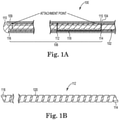
- Figure 1A illustrates one embodiment of the present invention as defined in the claims, comprising a cutaway view of a guidewire 100 with a core 102 extending proximally to a proximal end available for manipulation by the operator (not shown but is as well-known to the skilled artisan).
- Core 102 further comprises a distal end 104.
- Reformable tip 106 comprises a distal end 109, distal end comprising a distal tip 110 disposed thereon and which may be radiopaque.
- Reformable tip 106 further comprises a flattened shape memory material support coil 112, support coil 112 comprising a proximal end 114 and a distal end 116, proximal end 114 in attached disposition with the distal end of core 109 at attachment point 115.
- core 102 Surrounding at least part of the core 102 and the flattened material support coil 112 is a spring coil 118, at least a portion of which may be radiopaque.
- core 102 may comprise an outer diameter that is smaller than an inner diameter of support coil 112 at attachment point 115.
- core 102 may comprise an outer diameter that is larger than the inner diameter of support coil 112 at attachment point 115.
- core 102 may comprise an outer diameter that is larger than the outer diameter of support coil 112 at attachment point 115.
- Figure 1B illustrates the flattened material support coil 112 in closer detail.
- the shape memory material has been flattened to a desired thickness and cut to a desired width. Then, the shape memory material, thus cut, has been rolled and set or trained at high temperatures into the coiled structure of Fig. 1B .
- One embodiment of the coil 112 comprises the coil material having a thickness of 0.00175 inches, with a nominal inner diameter after shape setting in the coil form of approximately 0.0058 inches, though the skilled artisan will recognize the varying dimensions of the coil material, including the pitch, each such equivalent dimensional combination is within the scope of the present invention.
- Coil 112 is illustrated as comprising a left-hand winding, though a right-hand winding may also be used.
- the spring coil 118 which surrounds the coil 112, comprises an opposite winding, i.e., a right-hand winding.
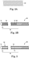
- FIG. 2A and 2B an alternate embodiment of the inventive guidewire 200 as defined in the claims is illustrated.
- This embodiment is identical to that of Figures 1A and 1B except that a loose braid 202 comprising stainless steel, a polymer or a shape memory material, or a combination thereof, is provided along the reformable tip 106 from the distal end of the support coil 109 to the proximal end of the support coil 114.
- the loose braid 202 may be applied around external surface 120 of the support coil 112 with the spring coil 118 surrounding the loose braid 202 and support coil 112.
- the loose braid 202 may be disposed between wire turns of the support coil 112.
- Figure 3 illustrates yet another embodiment of a guidewire 300 of the present invention as defined in the claims.
- a polymer sleeve 302 is provided along and the reformable tip 106.
- Polymer sleeve 302 may comprise nylon, pebax, fluorinated ethylene propylene (FEP), polytetrafluoroethylene (PTFE) and/or perfluoroalkoxy polymer resin (PFA).
- FEP fluorinated ethylene propylene
- PTFE polytetrafluoroethylene
- PFA perfluoroalkoxy polymer resin
- the polymer sleeve 302 may cover the external surface 120 of the support coil 112, with the spring coil 118 surrounding the support coil 112 and polymer sleeve 302.
- the polymer sleeve 302 may be disposed over the wire turns of the support coil 112 along the corresponding length of the reformable tip 106. Still more alternatively, the wire turns of support coil 112 may be embedded within a polymer sleeve. According to the present disclosure, the polymer sleeve 302 may be employed in guidewire 300 instead of the support coil 112, serving the same function as the embodiment having the support coil 112.
- the guidewire and reformable tip thereof may comprise a hydrophilic coating along at least the reformable tip 106 and in certain embodiments along the length of the guidewire, and may further comprise a coating of silicone over the hydrophilic coating and/or along the length of the guidewire. This coating treatment assists and eases positioning of the guidewire as well as provides increased deliverability of adjunctive devices along the positioned guidewire.
- the guidewire having a reformable tip as described herein results in a reformable tip that is more flexible than known guidewire tips, which greatly reduces the risk of perforation during an intravascular procedure.
Description
- The present invention is related to a guidewire comprising a core and a reformable tip comprising a support coil.
- A variety of techniques and instruments have been developed for use in the removal or repair of tissue in arteries and similar body passageways. A frequent objective of such techniques and instruments is the removal of atherosclerotic plaque in a patient's arteries. Atherosclerosis is characterized by the buildup of fatty deposits (atheromas) in the intimal layer (i.e., under the endothelium) of a patient's blood vessels. Very often over time what initially is deposited as relatively soft, cholesterol-rich atheromatous material hardens into a calcified atherosclerotic plaque. Such atheromas restrict the flow of blood, and therefore often are referred to as stenotic lesions or stenoses, the blocking material being referred to as stenotic material. If left untreated, such stenoses can cause angina, hypertension, myocardial infarction, strokes and the like.
- Several kinds of atherectomy devices have been developed for attempting to remove some or all of such stenotic material. In one type of device, such as that shown in
U.S. Pat. No. 4,990,134 (Auth ), a rotating burr covered with an abrasive cutting material, such as diamond grit (diamond particles or dust), is carried at the distal end of a flexible, rotatable drive shaft. -
U.S. Pat. No. 5,314,438 (Shturman ) shows another atherectomy device having a rotatable drive shaft with a section of the drive shaft having an enlarged diameter, at least a segment of this enlarged diameter section being covered with an abrasive material to define an abrasive segment of the drive shaft. When rotated at high speeds, the abrasive segment is capable of removing stenotic tissue from an artery. - Intravascular procedures, for example and without limitation, rotational atherectomy systems, require a guidewire. Known guidewires used in traversing blood vessels may bend and may ultimately deform permanently during a procedure and, therefore, become unusuable as well as potentially harmful to the patient. In this case, deformed guidewires must be removed and a replacement guidewire threaded to the region of interest within a patient's vasculature.
- Particularly, in a high-speed orbital atherectomy system, created by high-speed rotation of an eccentric abrasive drive shaft element, such as marketed by Cardiovascular Systems, Inc., ("CSI"), the stress forces and resulting fatigue on the guidewire can be permanently damaging. Primarily, in the case of CSI's systems, the guidewire is used in a high-speed atherectomy device that involves an eccentric abrasive element, having a center of mass that is radially positioned outwardly away from the rotational axis of the drive shaft to which the eccentric abrasive element is attached. High-speed rotation of this eccentric abrasive element thus results in orbital motion, i.e., a working diameter for the abrasive element that is larger than its resting diameter. Stated differently, the rotating eccentric abrasive element and surrounding portions of the rotational drive shaft to which it is attached experience radial excursions away from the resting rotational axis of the drive shaft. This concept is described fully in
US Patent 6,494,890 . This radial, or orbital, motion, causes high levels of forces to be transferred to the guidewire where damage may occur, even in cases where the guidewire uses a nitinol core for the guidewire tip. - Accordingly, there exists a need for a guidewire that comprises a tip that is capable of elastic deformation caused by very high forces as described supra, but also capable of returning and recovering back to the original undeformed shape and structure.
-
US 5,065,769 is related to a medical guidewire having a distal tip portion for advancement through a body by application of force to a proximal end portion, comprising an elongated multifilar coil structure element, and disposed thereabout and along a substantial portion of the length of the structural element, a sheath formed of a material that is non-corrosive within the body, the sheath being adapted to flex in unison with the structural element without kinking, the sheath and structural element in combination having a torque response along the joined length approaching 1:1, thereby allowing control of the distal tip at the guidewire within a body by application of rotational force to the proximal end portion outside the body. - The problem underlying the present invention is solved by the subject matter of the attached independent claim; preferred embodiments may be taken from the attached dependent claims.
- More specifically, the problem underlying the present invention is solved by
- a guidewire (100, 200, 300), comprising:
- a core (102) having a proximal end and a distal end (104) and at least partially surrounded by a spring coil (118) comprising wire turns;
- a reformable tip (106) having a distal end (109), a distal tip (110) disposed on the distal end (109), and a proximal end, wherein the proximal end of the reformable tip (106) and the distal end (104) of the core (102) are attached, the reformable tip (106) further comprising
- a support coil (112) comprising an external surface, an inner diameter, an outer diameter and a pitch, the support coil (112) further comprising a proximal end (114) and a distal end (116), the distal end (116) of the support coil (112) in communication with the distal tip (110), wherein the spring coil (118) further surrounds an external surface of the support coil (112),
- characterized in that
- the proximal end (114) of the support coil (112) is in attached communication with the distal end (104) of the core (102) such that the core (102) does not extend distally of the proximal end (114) of the support coil (112), and that the support coil is formed from a flattened shape memory material.
- In an embodiment, the shape memory material comprises nitinol.
- In an embodiment, the guidewire further comprises a loose braid (202) surrounding the external surface of the support coil (112).
- In a preferred embodiment thereof, the loose braid (202) is made of one or more of the group consisting of: stainless steel, nitinol, and a polymer.
- In an embodiment, the guidewire further comprises a loose braid (202) interposed between at least some of the wire turns of the spring coil (118).
- In a preferred embodiment thereof, the loose braid (202) is made of one or more of the group consisting of: stainless steel, nitinol, and a polymer.
- In an embodiment, the guidewire further comprises a polymer sleeve (302) surrounding the external surface of the support coil (112).
- In a preferred embodiment thereof, the polymer sleeve (302) is made of one or more of the group consisting of: nylon, pebax, fluorinated ethylene propylene (FEP), polytetrafluoroethylene (PTFE) and perfluoroalkoxy polymer resin (PFA).
- In an embodiment, the guidewire further comprises a polymer sleeve (302) surrounding the spring coil (118).
- In a preferred embodiment thereof, the polymer sleeve (302) is made of one or more of the group consisting of: nylon, pebax, fluorinated ethylene propylene (FEP), polytetrafluoroethylene (PTFE) and perfluoroalkoxy polymer resin (PFA).
- In an embodiment, the guidewire further comprises the wire turns of the guidewire (300) embedded within a polymer sleeve (302).
- In a preferred embodiment thereof, the polymer sleeve (302) is made of one or more of the group consisting of: nylon, pebax, fluorinated ethylene propylene (FEP), polytetrafluoroethylene (PTFE) and perfluoroalkoxy polymer resin (PFA).
- According to the present invention as defined in the claims, devices for providing an elastically deforming guidewire tip, capable of withstanding the extreme forces of, for example and without limitation, high-speed rotational atherectomy, in particular orbital motion induced by an eccentric abrasive head, are provided. The guidewire tip may be used in other procedures and may be a standalone device. In certain embodiments of the invention as defined in the claims, the reformable tip comprises an inner nitinol support coil, wherein the reformable tip may be attached to a larger proximal core for improved kink resistance and support for delivering adjunctive devices. In other embodiments of the invention as defined in the claims, an inner support ribbon coil, constructed of a shape-memory material, e.g., Nitinol, may be wrapped with a braided coil and/or a polymer sleeve. In other embodiments of the invention as defined in the claims, the braided coil and/or polymer sleeve may serve the same function as the inner support ribbon coil and replace the inner support ribbon coil. The resulting tip is more flexible with reduced risk of perforation than known guidewire tips.
-
-
Figure 1A illustrates one embodiment of the present invention as defined in the claims in cross-sectional and cutaway view; -
Figure 1B illustrates one embodiment of a shape-memory ribbon coil of the present invention as defined in the claims in side view; -
Figure 2A illustrates one embodiment of a braided coil of the present invention as defined in the claims in side view; -
Figure 2B illustrates one embodiment of the present invention as defined in the claims in cross-sectional and cutaway view; -
Figure 3 illustrates one embodiment of the present invention as defined in the claims in cross-sectional and cutaway view; - In the following detailed description of the various embodiments illustrated in the appended figures, like components and elements are identified using like reference numerals.
-
Figure 1A illustrates one embodiment of the present invention as defined in the claims, comprising a cutaway view of aguidewire 100 with acore 102 extending proximally to a proximal end available for manipulation by the operator (not shown but is as well-known to the skilled artisan).Core 102 further comprises adistal end 104.Reformable tip 106 comprises adistal end 109, distal end comprising adistal tip 110 disposed thereon and which may be radiopaque.Reformable tip 106 further comprises a flattened shape memorymaterial support coil 112,support coil 112 comprising aproximal end 114 and adistal end 116,proximal end 114 in attached disposition with the distal end ofcore 109 atattachment point 115. Surrounding at least part of thecore 102 and the flattenedmaterial support coil 112 is aspring coil 118, at least a portion of which may be radiopaque. In some embodiments as defined in the claims,core 102 may comprise an outer diameter that is smaller than an inner diameter ofsupport coil 112 atattachment point 115. Alternatively,core 102 may comprise an outer diameter that is larger than the inner diameter ofsupport coil 112 atattachment point 115. Still more alternatively,core 102 may comprise an outer diameter that is larger than the outer diameter ofsupport coil 112 atattachment point 115. -
Figure 1B illustrates the flattenedmaterial support coil 112 in closer detail. As can be seen, the shape memory material has been flattened to a desired thickness and cut to a desired width. Then, the shape memory material, thus cut, has been rolled and set or trained at high temperatures into the coiled structure ofFig. 1B . One embodiment of thecoil 112 comprises the coil material having a thickness of 0.00175 inches, with a nominal inner diameter after shape setting in the coil form of approximately 0.0058 inches, though the skilled artisan will recognize the varying dimensions of the coil material, including the pitch, each such equivalent dimensional combination is within the scope of the present invention.Coil 112 is illustrated as comprising a left-hand winding, though a right-hand winding may also be used. In the case of the illustrated left-hand winding, thespring coil 118 which surrounds thecoil 112, comprises an opposite winding, i.e., a right-hand winding. Again, the skilled artisan will recognize the equivalence of the winding directions for these elements, each combination is within the scope of the present invention as defined in the claims. - Turning now to
Figures 2A and 2B , an alternate embodiment of theinventive guidewire 200 as defined in the claims is illustrated. This embodiment is identical to that ofFigures 1A and 1B except that aloose braid 202 comprising stainless steel, a polymer or a shape memory material, or a combination thereof, is provided along thereformable tip 106 from the distal end of thesupport coil 109 to the proximal end of thesupport coil 114. Theloose braid 202 may be applied aroundexternal surface 120 of thesupport coil 112 with thespring coil 118 surrounding theloose braid 202 andsupport coil 112. Alternatively, theloose braid 202 may be disposed between wire turns of thesupport coil 112. -
Figure 3 illustrates yet another embodiment of aguidewire 300 of the present invention as defined in the claims. In this embodiment, which is identical to that ofFigures 2A and 2B except that, instead of theloose braid 202, apolymer sleeve 302 is provided along and thereformable tip 106.Polymer sleeve 302 may comprise nylon, pebax, fluorinated ethylene propylene (FEP), polytetrafluoroethylene (PTFE) and/or perfluoroalkoxy polymer resin (PFA). In this embodiment, thepolymer sleeve 302 may cover theexternal surface 120 of thesupport coil 112, with thespring coil 118 surrounding thesupport coil 112 andpolymer sleeve 302. Alternatively, thepolymer sleeve 302 may be disposed over the wire turns of thesupport coil 112 along the corresponding length of thereformable tip 106. Still more alternatively, the wire turns ofsupport coil 112 may be embedded within a polymer sleeve. According to the present disclosure, thepolymer sleeve 302 may be employed inguidewire 300 instead of thesupport coil 112, serving the same function as the embodiment having thesupport coil 112. - In various embodiments of the invention as defined in the claims, the guidewire and reformable tip thereof may comprise a hydrophilic coating along at least the
reformable tip 106 and in certain embodiments along the length of the guidewire, and may further comprise a coating of silicone over the hydrophilic coating and/or along the length of the guidewire. This coating treatment assists and eases positioning of the guidewire as well as provides increased deliverability of adjunctive devices along the positioned guidewire. - In various embodiments of the invention as defined in the claims, the guidewire having a reformable tip as described herein results in a reformable tip that is more flexible than known guidewire tips, which greatly reduces the risk of perforation during an intravascular procedure.
Claims (12)
- A guidewire (100, 200, 300), comprising:a core (102) having a proximal end and a distal end (104) and at least partially surrounded by a spring coil (118) comprising wire turns;a reformable tip (106) having a distal end (109), a distal tip (110) disposed on the distal end (109), and a proximal end, wherein the proximal end of the reformable tip (106) and the distal end (104) of the core (102) are attached, the reformable tip (106) further comprisinga support coil (112) comprising an external surface, an inner diameter, an outer diameter and a pitch, the support coil (112) further comprising a proximal end (114) and a distal end (116), the distal end (116) of the support coil (112) in communication with the distal tip (110), wherein the spring coil (118) further surrounds an external surface of the support coil (112),characterized in that
the proximal end (114) of the support coil (112) is in attached communication with the distal end (104) of the core (102) such that the core (102) does not extend distally of the proximal end (114) of the support coil (112), and that the support coil is formed from a flattened shape memory material. - The guidewire (100, 200, 300) of claim 1, wherein the shape memory material comprises nitinol.
- The guidewire (200) of claim 1, further comprising a loose braid (202) surrounding the external surface of the support coil (112).
- The guidewire (200) of claim 3, wherein the loose braid (202) is made of one or more of the group consisting of: stainless steel, nitinol, and a polymer.
- The guidewire (200) of claim 1, further comprising a loose braid (202) interposed between at least some of the wire turns of the spring coil (118).
- The guidewire (200) of claim 5, wherein the loose braid (202) is made of one or more of the group consisting of: stainless steel, nitinol, and a polymer.
- The guidewire (300) of claim 1, further comprising a polymer sleeve (302) surrounding the external surface of the support coil (112).
- The guidewire (300) of claim 7, wherein the polymer sleeve (302) is made of one or more of the group consisting of: nylon, pebax, fluorinated ethylene propylene (FEP), polytetrafluoroethylene (PTFE) and perfluoroalkoxy polymer resin (PFA).
- The guidewire (300) of claim 1, further comprising a polymer sleeve (302) surrounding the spring coil (118).
- The guidewire (300) of claim 9, wherein the polymer sleeve (302) is made of one or more of the group consisting of: nylon, pebax, fluorinated ethylene propylene (FEP), polytetrafluoroethylene (PTFE) and perfluoroalkoxy polymer resin (PFA).
- The guidewire (300) of claim 1, further comprising the wire turns of the guidewire (300) embedded within a polymer sleeve (302).
- The guidewire (300) of claim 11, wherein the polymer sleeve (302) is made of one or more of the group consisting of: nylon, pebax, fluorinated ethylene propylene (FEP), polytetrafluoroethylene (PTFE) and perfluoroalkoxy polymer resin (PFA).
Applications Claiming Priority (3)
| Application Number | Priority Date | Filing Date | Title |
|---|---|---|---|
| US201462033346P | 2014-08-05 | 2014-08-05 | |
| US14/816,367 US10806905B2 (en) | 2014-08-05 | 2015-08-03 | Reformable guidewire tip |
| PCT/US2015/043521 WO2016022512A1 (en) | 2014-08-05 | 2015-08-04 | Reformable guidewire tip |
Publications (3)
| Publication Number | Publication Date |
|---|---|
| EP3185787A1 EP3185787A1 (en) | 2017-07-05 |
| EP3185787A4 EP3185787A4 (en) | 2018-03-28 |
| EP3185787B1 true EP3185787B1 (en) | 2022-03-09 |
Family
ID=55264406
Family Applications (1)
| Application Number | Title | Priority Date | Filing Date |
|---|---|---|---|
| EP15829252.4A Active EP3185787B1 (en) | 2014-08-05 | 2015-08-04 | Reformable guidewire tip |
Country Status (7)
| Country | Link |
|---|---|
| US (1) | US10806905B2 (en) |
| EP (1) | EP3185787B1 (en) |
| JP (1) | JP6868551B2 (en) |
| CN (1) | CN106572865B (en) |
| AU (1) | AU2015301290A1 (en) |
| CA (1) | CA2956680A1 (en) |
| WO (1) | WO2016022512A1 (en) |
Families Citing this family (4)
| Publication number | Priority date | Publication date | Assignee | Title |
|---|---|---|---|---|
| USD867589S1 (en) * | 2017-03-23 | 2019-11-19 | Pioneer Medical Instrument Co., Ltd. | Steerable structure for endoscope |
| EP3434310B1 (en) | 2017-07-26 | 2023-06-21 | Heraeus Medical Components, LLC | Resilient tip and method |
| US11033721B2 (en) * | 2018-06-22 | 2021-06-15 | Acclarent, Inc. | Guidewire for dilating eustachian tube via middle ear |
| US20210393924A1 (en) * | 2020-06-19 | 2021-12-23 | Becton, Dickinson And Company | Vascular access instrument and related devices and methods |
Family Cites Families (31)
| Publication number | Priority date | Publication date | Assignee | Title |
|---|---|---|---|---|
| CA1293663C (en) | 1986-01-06 | 1991-12-31 | David Christopher Auth | Transluminal microdissection device |
| US4763647A (en) * | 1987-01-06 | 1988-08-16 | C. R. Bard, Inc. | Dual coil steerable guidewire |
| US5065769A (en) | 1988-11-23 | 1991-11-19 | Boston Scientific Corporation | Small diameter guidewires of multi-filar, cross-wound coils |
| US5211636A (en) * | 1990-10-31 | 1993-05-18 | Lake Region Manufacturing Co., Inc. | Steerable infusion guide wire |
| US5312427A (en) * | 1992-10-16 | 1994-05-17 | Shturman Cardiology Systems, Inc. | Device and method for directional rotational atherectomy |
| US5360432A (en) * | 1992-10-16 | 1994-11-01 | Shturman Cardiology Systems, Inc. | Abrasive drive shaft device for directional rotational atherectomy |
| US5836868A (en) * | 1992-11-13 | 1998-11-17 | Scimed Life Systems, Inc. | Expandable intravascular occlusion material removal devices and methods of use |
| US5596996A (en) * | 1995-03-30 | 1997-01-28 | Medtronic, Inc. | High support nitinol tube guidewire with plastic plug transition |
| US5827201A (en) * | 1996-07-26 | 1998-10-27 | Target Therapeutics, Inc. | Micro-braided guidewire |
| US6494890B1 (en) | 1997-08-14 | 2002-12-17 | Shturman Cardiology Systems, Inc. | Eccentric rotational atherectomy device |
| US6132444A (en) * | 1997-08-14 | 2000-10-17 | Shturman Cardiology Systems, Inc. | Eccentric drive shaft for atherectomy device and method for manufacture |
| US6824550B1 (en) * | 2000-04-06 | 2004-11-30 | Norbon Medical, Inc. | Guidewire for crossing occlusions or stenosis |
| JP2886151B1 (en) | 1998-03-17 | 1999-04-26 | 株式会社日本エスコ | Disposer mounting structure |
| US6496890B1 (en) * | 1999-12-03 | 2002-12-17 | Michael Joseph Azevedo | Bus hang prevention and recovery for data communication systems employing a shared bus interface with multiple bus masters |
| US7150723B2 (en) * | 2001-11-29 | 2006-12-19 | C-I-Medic Co., Ltd. | Medical device including guide wire and balloon catheter for curing a coronary artery |
| US7608058B2 (en) * | 2002-07-23 | 2009-10-27 | Micrus Corporation | Stretch resistant therapeutic device |
| US8113916B2 (en) | 2003-01-17 | 2012-02-14 | Boston Scientific Scimed, Inc. | Straightening and centerless grinding of wire for use with medical devices |
| US7785273B2 (en) | 2003-09-22 | 2010-08-31 | Boston Scientific Scimed, Inc. | Guidewire with reinforcing member |
| US7998090B2 (en) * | 2004-08-31 | 2011-08-16 | Abbott Cardiovascular Systems Inc. | Guide wire with core having welded wire segments |
| US9320831B2 (en) * | 2005-03-04 | 2016-04-26 | W. L. Gore & Associates, Inc. | Polymer shrink tubes and novel uses therefor |
| US20090018566A1 (en) * | 2006-06-30 | 2009-01-15 | Artheromed, Inc. | Atherectomy devices, systems, and methods |
| CN101652156B (en) * | 2007-02-08 | 2013-12-25 | C.R.巴德有限公司 | Shape memory medical device and methods of use |
| AU2008359873B8 (en) * | 2007-07-27 | 2015-09-10 | Microvention, Inc. | Detachable coil incorporating stretch resistance |
| US8034075B2 (en) * | 2007-11-09 | 2011-10-11 | Micrus Endovascular Corporation | Tethered coil for treatment of body lumens |
| US8728097B1 (en) * | 2008-02-26 | 2014-05-20 | Mitralign, Inc. | Tissue plication devices and methods for their use |
| JP4993632B2 (en) * | 2009-06-16 | 2012-08-08 | 朝日インテック株式会社 | Medical guidewire |
| US20110060316A1 (en) * | 2009-09-04 | 2011-03-10 | Dicarlo Paul | Tipped Ribbon Integrated Guidewire |
| US20120172905A1 (en) | 2010-12-30 | 2012-07-05 | Kimberly-Clark, Inc. | Tissue Removal Apparatus and Method of Manufacturing Same |
| US10130789B2 (en) * | 2011-06-30 | 2018-11-20 | Covidien Lp | Distal access aspiration guide catheter |
| CN103957825B (en) | 2011-10-13 | 2018-12-07 | 阿瑟罗迈德公司 | Atherectomy device, system and method |
| CN203591293U (en) * | 2013-12-04 | 2014-05-14 | 王玉峰 | Spring ring system |
-
2015
- 2015-08-03 US US14/816,367 patent/US10806905B2/en active Active
- 2015-08-04 EP EP15829252.4A patent/EP3185787B1/en active Active
- 2015-08-04 AU AU2015301290A patent/AU2015301290A1/en not_active Abandoned
- 2015-08-04 CN CN201580041956.9A patent/CN106572865B/en active Active
- 2015-08-04 CA CA2956680A patent/CA2956680A1/en not_active Abandoned
- 2015-08-04 WO PCT/US2015/043521 patent/WO2016022512A1/en active Application Filing
- 2015-08-04 JP JP2017506360A patent/JP6868551B2/en active Active
Also Published As
| Publication number | Publication date |
|---|---|
| JP6868551B2 (en) | 2021-05-12 |
| EP3185787A4 (en) | 2018-03-28 |
| US20160038719A1 (en) | 2016-02-11 |
| US10806905B2 (en) | 2020-10-20 |
| CN106572865A (en) | 2017-04-19 |
| CN106572865B (en) | 2020-10-30 |
| CA2956680A1 (en) | 2016-02-11 |
| WO2016022512A1 (en) | 2016-02-11 |
| JP2017527347A (en) | 2017-09-21 |
| AU2015301290A1 (en) | 2017-02-09 |
| EP3185787A1 (en) | 2017-07-05 |
Similar Documents
| Publication | Publication Date | Title |
|---|---|---|
| EP1898808B1 (en) | A rotational atherectomy device and method of use | |
| US9101387B2 (en) | Directional rotational atherectomy device with offset spinning abrasive element | |
| US5897566A (en) | Rotational atherectomy device | |
| EP2429424B1 (en) | Rotational atherectomy device to improve abrading efficiency | |
| US8551128B2 (en) | Rotational atherectomy device with pre-curved drive shaft | |
| EP3185787B1 (en) | Reformable guidewire tip | |
| US9289230B2 (en) | Rotational atherectomy device with a system of eccentric abrading heads | |
| US11432840B2 (en) | Rotational systems comprising a polymer driveshaft | |
| US20060074442A1 (en) | Guidewire for crossing occlusions or stenoses | |
| US20050119615A1 (en) | Guidewire for crossing occlusions or stenoses | |
| JP2011518604A (en) | Method and apparatus for traversing a vessel occlusion | |
| US20150094749A1 (en) | Devices, systems and methods for a piloting tip bushing for rotational atherectomy | |
| CN108882947B (en) | Rotary cutting device with eccentric grinding head system | |
| CN115461000A (en) | Atherectomy device comprising a sealed drive shaft | |
| US20240115289A1 (en) | Rotational drive shafts and intravascular medical devices thereof | |
| US11266437B2 (en) | Drive shaft with metallic inner layer and polymer jacket | |
| US20230063136A1 (en) | Tissue-Removing Catheter with Distal Tip | |
| US11690645B2 (en) | Tissue-removing catheter | |
| WO2024083314A1 (en) | A rotational atherectomy device | |
| WO2016094386A1 (en) | Devices, systems and methods for a piloting tip bushing for rotational atherectomy |
Legal Events
| Date | Code | Title | Description |
|---|---|---|---|
| STAA | Information on the status of an ep patent application or granted ep patent |
Free format text: STATUS: THE INTERNATIONAL PUBLICATION HAS BEEN MADE |
|
| PUAI | Public reference made under article 153(3) epc to a published international application that has entered the european phase |
Free format text: ORIGINAL CODE: 0009012 |
|
| STAA | Information on the status of an ep patent application or granted ep patent |
Free format text: STATUS: REQUEST FOR EXAMINATION WAS MADE |
|
| 17P | Request for examination filed |
Effective date: 20170223 |
|
| AK | Designated contracting states |
Kind code of ref document: A1 Designated state(s): AL AT BE BG CH CY CZ DE DK EE ES FI FR GB GR HR HU IE IS IT LI LT LU LV MC MK MT NL NO PL PT RO RS SE SI SK SM TR |
|
| AX | Request for extension of the european patent |
Extension state: BA ME |
|
| DAV | Request for validation of the european patent (deleted) | ||
| DAX | Request for extension of the european patent (deleted) | ||
| A4 | Supplementary search report drawn up and despatched |
Effective date: 20180222 |
|
| RIC1 | Information provided on ipc code assigned before grant |
Ipc: A61B 17/32 20060101ALI20180217BHEP Ipc: A61M 25/09 20060101ALI20180217BHEP Ipc: A61B 17/22 20060101ALI20180217BHEP Ipc: A61B 17/3207 20060101AFI20180217BHEP Ipc: A61B 17/00 20060101ALI20180217BHEP |
|
| REG | Reference to a national code |
Ref country code: HK Ref legal event code: DE Ref document number: 1238116 Country of ref document: HK |
|
| STAA | Information on the status of an ep patent application or granted ep patent |
Free format text: STATUS: EXAMINATION IS IN PROGRESS |
|
| 17Q | First examination report despatched |
Effective date: 20200720 |
|
| STAA | Information on the status of an ep patent application or granted ep patent |
Free format text: STATUS: EXAMINATION IS IN PROGRESS |
|
| GRAJ | Information related to disapproval of communication of intention to grant by the applicant or resumption of examination proceedings by the epo deleted |
Free format text: ORIGINAL CODE: EPIDOSDIGR1 |
|
| STAA | Information on the status of an ep patent application or granted ep patent |
Free format text: STATUS: GRANT OF PATENT IS INTENDED |
|
| GRAP | Despatch of communication of intention to grant a patent |
Free format text: ORIGINAL CODE: EPIDOSNIGR1 |
|
| STAA | Information on the status of an ep patent application or granted ep patent |
Free format text: STATUS: GRANT OF PATENT IS INTENDED |
|
| INTG | Intention to grant announced |
Effective date: 20211005 |
|
| RIN1 | Information on inventor provided before grant (corrected) |
Inventor name: ASMUS, BRUCE H. |
|
| GRAS | Grant fee paid |
Free format text: ORIGINAL CODE: EPIDOSNIGR3 |
|
| GRAA | (expected) grant |
Free format text: ORIGINAL CODE: 0009210 |
|
| STAA | Information on the status of an ep patent application or granted ep patent |
Free format text: STATUS: THE PATENT HAS BEEN GRANTED |
|
| AK | Designated contracting states |
Kind code of ref document: B1 Designated state(s): AL AT BE BG CH CY CZ DE DK EE ES FI FR GB GR HR HU IE IS IT LI LT LU LV MC MK MT NL NO PL PT RO RS SE SI SK SM TR |
|
| REG | Reference to a national code |
Ref country code: GB Ref legal event code: FG4D |
|
| REG | Reference to a national code |
Ref country code: CH Ref legal event code: EP Ref country code: AT Ref legal event code: REF Ref document number: 1473503 Country of ref document: AT Kind code of ref document: T Effective date: 20220315 |
|
| REG | Reference to a national code |
Ref country code: IE Ref legal event code: FG4D |
|
| REG | Reference to a national code |
Ref country code: DE Ref legal event code: R096 Ref document number: 602015077449 Country of ref document: DE |
|
| REG | Reference to a national code |
Ref country code: NL Ref legal event code: FP |
|
| REG | Reference to a national code |
Ref country code: LT Ref legal event code: MG9D |
|
| PG25 | Lapsed in a contracting state [announced via postgrant information from national office to epo] |
Ref country code: SE Free format text: LAPSE BECAUSE OF FAILURE TO SUBMIT A TRANSLATION OF THE DESCRIPTION OR TO PAY THE FEE WITHIN THE PRESCRIBED TIME-LIMIT Effective date: 20220309 Ref country code: RS Free format text: LAPSE BECAUSE OF FAILURE TO SUBMIT A TRANSLATION OF THE DESCRIPTION OR TO PAY THE FEE WITHIN THE PRESCRIBED TIME-LIMIT Effective date: 20220309 Ref country code: NO Free format text: LAPSE BECAUSE OF FAILURE TO SUBMIT A TRANSLATION OF THE DESCRIPTION OR TO PAY THE FEE WITHIN THE PRESCRIBED TIME-LIMIT Effective date: 20220609 Ref country code: LT Free format text: LAPSE BECAUSE OF FAILURE TO SUBMIT A TRANSLATION OF THE DESCRIPTION OR TO PAY THE FEE WITHIN THE PRESCRIBED TIME-LIMIT Effective date: 20220309 Ref country code: HR Free format text: LAPSE BECAUSE OF FAILURE TO SUBMIT A TRANSLATION OF THE DESCRIPTION OR TO PAY THE FEE WITHIN THE PRESCRIBED TIME-LIMIT Effective date: 20220309 Ref country code: BG Free format text: LAPSE BECAUSE OF FAILURE TO SUBMIT A TRANSLATION OF THE DESCRIPTION OR TO PAY THE FEE WITHIN THE PRESCRIBED TIME-LIMIT Effective date: 20220609 |
|
| REG | Reference to a national code |
Ref country code: AT Ref legal event code: MK05 Ref document number: 1473503 Country of ref document: AT Kind code of ref document: T Effective date: 20220309 |
|
| PG25 | Lapsed in a contracting state [announced via postgrant information from national office to epo] |
Ref country code: LV Free format text: LAPSE BECAUSE OF FAILURE TO SUBMIT A TRANSLATION OF THE DESCRIPTION OR TO PAY THE FEE WITHIN THE PRESCRIBED TIME-LIMIT Effective date: 20220309 Ref country code: GR Free format text: LAPSE BECAUSE OF FAILURE TO SUBMIT A TRANSLATION OF THE DESCRIPTION OR TO PAY THE FEE WITHIN THE PRESCRIBED TIME-LIMIT Effective date: 20220610 Ref country code: FI Free format text: LAPSE BECAUSE OF FAILURE TO SUBMIT A TRANSLATION OF THE DESCRIPTION OR TO PAY THE FEE WITHIN THE PRESCRIBED TIME-LIMIT Effective date: 20220309 |
|
| PG25 | Lapsed in a contracting state [announced via postgrant information from national office to epo] |
Ref country code: SM Free format text: LAPSE BECAUSE OF FAILURE TO SUBMIT A TRANSLATION OF THE DESCRIPTION OR TO PAY THE FEE WITHIN THE PRESCRIBED TIME-LIMIT Effective date: 20220309 Ref country code: SK Free format text: LAPSE BECAUSE OF FAILURE TO SUBMIT A TRANSLATION OF THE DESCRIPTION OR TO PAY THE FEE WITHIN THE PRESCRIBED TIME-LIMIT Effective date: 20220309 Ref country code: RO Free format text: LAPSE BECAUSE OF FAILURE TO SUBMIT A TRANSLATION OF THE DESCRIPTION OR TO PAY THE FEE WITHIN THE PRESCRIBED TIME-LIMIT Effective date: 20220309 Ref country code: PT Free format text: LAPSE BECAUSE OF FAILURE TO SUBMIT A TRANSLATION OF THE DESCRIPTION OR TO PAY THE FEE WITHIN THE PRESCRIBED TIME-LIMIT Effective date: 20220711 Ref country code: ES Free format text: LAPSE BECAUSE OF FAILURE TO SUBMIT A TRANSLATION OF THE DESCRIPTION OR TO PAY THE FEE WITHIN THE PRESCRIBED TIME-LIMIT Effective date: 20220309 Ref country code: EE Free format text: LAPSE BECAUSE OF FAILURE TO SUBMIT A TRANSLATION OF THE DESCRIPTION OR TO PAY THE FEE WITHIN THE PRESCRIBED TIME-LIMIT Effective date: 20220309 Ref country code: CZ Free format text: LAPSE BECAUSE OF FAILURE TO SUBMIT A TRANSLATION OF THE DESCRIPTION OR TO PAY THE FEE WITHIN THE PRESCRIBED TIME-LIMIT Effective date: 20220309 Ref country code: AT Free format text: LAPSE BECAUSE OF FAILURE TO SUBMIT A TRANSLATION OF THE DESCRIPTION OR TO PAY THE FEE WITHIN THE PRESCRIBED TIME-LIMIT Effective date: 20220309 |
|
| PG25 | Lapsed in a contracting state [announced via postgrant information from national office to epo] |
Ref country code: PL Free format text: LAPSE BECAUSE OF FAILURE TO SUBMIT A TRANSLATION OF THE DESCRIPTION OR TO PAY THE FEE WITHIN THE PRESCRIBED TIME-LIMIT Effective date: 20220309 Ref country code: IS Free format text: LAPSE BECAUSE OF FAILURE TO SUBMIT A TRANSLATION OF THE DESCRIPTION OR TO PAY THE FEE WITHIN THE PRESCRIBED TIME-LIMIT Effective date: 20220709 Ref country code: AL Free format text: LAPSE BECAUSE OF FAILURE TO SUBMIT A TRANSLATION OF THE DESCRIPTION OR TO PAY THE FEE WITHIN THE PRESCRIBED TIME-LIMIT Effective date: 20220309 |
|
| REG | Reference to a national code |
Ref country code: DE Ref legal event code: R097 Ref document number: 602015077449 Country of ref document: DE |
|
| PLBE | No opposition filed within time limit |
Free format text: ORIGINAL CODE: 0009261 |
|
| STAA | Information on the status of an ep patent application or granted ep patent |
Free format text: STATUS: NO OPPOSITION FILED WITHIN TIME LIMIT |
|
| PG25 | Lapsed in a contracting state [announced via postgrant information from national office to epo] |
Ref country code: DK Free format text: LAPSE BECAUSE OF FAILURE TO SUBMIT A TRANSLATION OF THE DESCRIPTION OR TO PAY THE FEE WITHIN THE PRESCRIBED TIME-LIMIT Effective date: 20220309 |
|
| 26N | No opposition filed |
Effective date: 20221212 |
|
| PG25 | Lapsed in a contracting state [announced via postgrant information from national office to epo] |
Ref country code: SI Free format text: LAPSE BECAUSE OF FAILURE TO SUBMIT A TRANSLATION OF THE DESCRIPTION OR TO PAY THE FEE WITHIN THE PRESCRIBED TIME-LIMIT Effective date: 20220309 |
|
| PG25 | Lapsed in a contracting state [announced via postgrant information from national office to epo] |
Ref country code: MC Free format text: LAPSE BECAUSE OF FAILURE TO SUBMIT A TRANSLATION OF THE DESCRIPTION OR TO PAY THE FEE WITHIN THE PRESCRIBED TIME-LIMIT Effective date: 20220309 |
|
| REG | Reference to a national code |
Ref country code: CH Ref legal event code: PL |
|
| REG | Reference to a national code |
Ref country code: NL Ref legal event code: MM Effective date: 20220901 |
|
| GBPC | Gb: european patent ceased through non-payment of renewal fee |
Effective date: 20220804 |
|
| PG25 | Lapsed in a contracting state [announced via postgrant information from national office to epo] |
Ref country code: LU Free format text: LAPSE BECAUSE OF NON-PAYMENT OF DUE FEES Effective date: 20220804 Ref country code: LI Free format text: LAPSE BECAUSE OF NON-PAYMENT OF DUE FEES Effective date: 20220831 Ref country code: CH Free format text: LAPSE BECAUSE OF NON-PAYMENT OF DUE FEES Effective date: 20220831 |
|
| REG | Reference to a national code |
Ref country code: BE Ref legal event code: MM Effective date: 20220831 |
|
| PG25 | Lapsed in a contracting state [announced via postgrant information from national office to epo] |
Ref country code: NL Free format text: LAPSE BECAUSE OF NON-PAYMENT OF DUE FEES Effective date: 20220901 |
|
| P01 | Opt-out of the competence of the unified patent court (upc) registered |
Effective date: 20230530 |
|
| PG25 | Lapsed in a contracting state [announced via postgrant information from national office to epo] |
Ref country code: IT Free format text: LAPSE BECAUSE OF FAILURE TO SUBMIT A TRANSLATION OF THE DESCRIPTION OR TO PAY THE FEE WITHIN THE PRESCRIBED TIME-LIMIT Effective date: 20220309 Ref country code: IE Free format text: LAPSE BECAUSE OF NON-PAYMENT OF DUE FEES Effective date: 20220804 |
|
| PG25 | Lapsed in a contracting state [announced via postgrant information from national office to epo] |
Ref country code: BE Free format text: LAPSE BECAUSE OF NON-PAYMENT OF DUE FEES Effective date: 20220831 |
|
| PG25 | Lapsed in a contracting state [announced via postgrant information from national office to epo] |
Ref country code: GB Free format text: LAPSE BECAUSE OF NON-PAYMENT OF DUE FEES Effective date: 20220804 |
|
| PGFP | Annual fee paid to national office [announced via postgrant information from national office to epo] |
Ref country code: FR Payment date: 20230710 Year of fee payment: 9 Ref country code: DE Payment date: 20230711 Year of fee payment: 9 |
|
| REG | Reference to a national code |
Ref country code: HK Ref legal event code: WD Ref document number: 1238116 Country of ref document: HK |
|
| PG25 | Lapsed in a contracting state [announced via postgrant information from national office to epo] |
Ref country code: HU Free format text: LAPSE BECAUSE OF FAILURE TO SUBMIT A TRANSLATION OF THE DESCRIPTION OR TO PAY THE FEE WITHIN THE PRESCRIBED TIME-LIMIT; INVALID AB INITIO Effective date: 20150804 |