EP3184786A1 - Controlling device for internal combustion engines - Google Patents
Controlling device for internal combustion engines Download PDFInfo
- Publication number
- EP3184786A1 EP3184786A1 EP14907603.6A EP14907603A EP3184786A1 EP 3184786 A1 EP3184786 A1 EP 3184786A1 EP 14907603 A EP14907603 A EP 14907603A EP 3184786 A1 EP3184786 A1 EP 3184786A1
- Authority
- EP
- European Patent Office
- Prior art keywords
- fuel
- fuel injection
- fuel cut
- injection valve
- combustion chamber
- Prior art date
- Legal status (The legal status is an assumption and is not a legal conclusion. Google has not performed a legal analysis and makes no representation as to the accuracy of the status listed.)
- Granted
Links
Images



Classifications
-
- F—MECHANICAL ENGINEERING; LIGHTING; HEATING; WEAPONS; BLASTING
- F02—COMBUSTION ENGINES; HOT-GAS OR COMBUSTION-PRODUCT ENGINE PLANTS
- F02D—CONTROLLING COMBUSTION ENGINES
- F02D41/00—Electrical control of supply of combustible mixture or its constituents
- F02D41/02—Circuit arrangements for generating control signals
- F02D41/04—Introducing corrections for particular operating conditions
- F02D41/12—Introducing corrections for particular operating conditions for deceleration
- F02D41/123—Introducing corrections for particular operating conditions for deceleration the fuel injection being cut-off
- F02D41/126—Introducing corrections for particular operating conditions for deceleration the fuel injection being cut-off transitional corrections at the end of the cut-off period
-
- F—MECHANICAL ENGINEERING; LIGHTING; HEATING; WEAPONS; BLASTING
- F02—COMBUSTION ENGINES; HOT-GAS OR COMBUSTION-PRODUCT ENGINE PLANTS
- F02D—CONTROLLING COMBUSTION ENGINES
- F02D29/00—Controlling engines, such controlling being peculiar to the devices driven thereby, the devices being other than parts or accessories essential to engine operation, e.g. controlling of engines by signals external thereto
- F02D29/02—Controlling engines, such controlling being peculiar to the devices driven thereby, the devices being other than parts or accessories essential to engine operation, e.g. controlling of engines by signals external thereto peculiar to engines driving vehicles; peculiar to engines driving variable pitch propellers
-
- F—MECHANICAL ENGINEERING; LIGHTING; HEATING; WEAPONS; BLASTING
- F02—COMBUSTION ENGINES; HOT-GAS OR COMBUSTION-PRODUCT ENGINE PLANTS
- F02D—CONTROLLING COMBUSTION ENGINES
- F02D41/00—Electrical control of supply of combustible mixture or its constituents
- F02D41/02—Circuit arrangements for generating control signals
- F02D41/021—Introducing corrections for particular conditions exterior to the engine
- F02D41/0235—Introducing corrections for particular conditions exterior to the engine in relation with the state of the exhaust gas treating apparatus
- F02D41/024—Introducing corrections for particular conditions exterior to the engine in relation with the state of the exhaust gas treating apparatus to increase temperature of the exhaust gas treating apparatus
- F02D41/025—Introducing corrections for particular conditions exterior to the engine in relation with the state of the exhaust gas treating apparatus to increase temperature of the exhaust gas treating apparatus by changing the composition of the exhaust gas, e.g. for exothermic reaction on exhaust gas treating apparatus
-
- F—MECHANICAL ENGINEERING; LIGHTING; HEATING; WEAPONS; BLASTING
- F02—COMBUSTION ENGINES; HOT-GAS OR COMBUSTION-PRODUCT ENGINE PLANTS
- F02D—CONTROLLING COMBUSTION ENGINES
- F02D41/00—Electrical control of supply of combustible mixture or its constituents
- F02D41/02—Circuit arrangements for generating control signals
- F02D41/021—Introducing corrections for particular conditions exterior to the engine
- F02D41/0235—Introducing corrections for particular conditions exterior to the engine in relation with the state of the exhaust gas treating apparatus
- F02D41/0295—Control according to the amount of oxygen that is stored on the exhaust gas treating apparatus
-
- F—MECHANICAL ENGINEERING; LIGHTING; HEATING; WEAPONS; BLASTING
- F02—COMBUSTION ENGINES; HOT-GAS OR COMBUSTION-PRODUCT ENGINE PLANTS
- F02D—CONTROLLING COMBUSTION ENGINES
- F02D41/00—Electrical control of supply of combustible mixture or its constituents
- F02D41/02—Circuit arrangements for generating control signals
- F02D41/04—Introducing corrections for particular operating conditions
- F02D41/047—Taking into account fuel evaporation or wall wetting
-
- F—MECHANICAL ENGINEERING; LIGHTING; HEATING; WEAPONS; BLASTING
- F02—COMBUSTION ENGINES; HOT-GAS OR COMBUSTION-PRODUCT ENGINE PLANTS
- F02D—CONTROLLING COMBUSTION ENGINES
- F02D41/00—Electrical control of supply of combustible mixture or its constituents
- F02D41/30—Controlling fuel injection
- F02D41/38—Controlling fuel injection of the high pressure type
-
- F—MECHANICAL ENGINEERING; LIGHTING; HEATING; WEAPONS; BLASTING
- F02—COMBUSTION ENGINES; HOT-GAS OR COMBUSTION-PRODUCT ENGINE PLANTS
- F02P—IGNITION, OTHER THAN COMPRESSION IGNITION, FOR INTERNAL-COMBUSTION ENGINES; TESTING OF IGNITION TIMING IN COMPRESSION-IGNITION ENGINES
- F02P5/00—Advancing or retarding ignition; Control therefor
- F02P5/04—Advancing or retarding ignition; Control therefor automatically, as a function of the working conditions of the engine or vehicle or of the atmospheric conditions
- F02P5/045—Advancing or retarding ignition; Control therefor automatically, as a function of the working conditions of the engine or vehicle or of the atmospheric conditions combined with electronic control of other engine functions, e.g. fuel injection
-
- F—MECHANICAL ENGINEERING; LIGHTING; HEATING; WEAPONS; BLASTING
- F02—COMBUSTION ENGINES; HOT-GAS OR COMBUSTION-PRODUCT ENGINE PLANTS
- F02P—IGNITION, OTHER THAN COMPRESSION IGNITION, FOR INTERNAL-COMBUSTION ENGINES; TESTING OF IGNITION TIMING IN COMPRESSION-IGNITION ENGINES
- F02P5/00—Advancing or retarding ignition; Control therefor
- F02P5/04—Advancing or retarding ignition; Control therefor automatically, as a function of the working conditions of the engine or vehicle or of the atmospheric conditions
- F02P5/145—Advancing or retarding ignition; Control therefor automatically, as a function of the working conditions of the engine or vehicle or of the atmospheric conditions using electrical means
-
- F—MECHANICAL ENGINEERING; LIGHTING; HEATING; WEAPONS; BLASTING
- F02—COMBUSTION ENGINES; HOT-GAS OR COMBUSTION-PRODUCT ENGINE PLANTS
- F02P—IGNITION, OTHER THAN COMPRESSION IGNITION, FOR INTERNAL-COMBUSTION ENGINES; TESTING OF IGNITION TIMING IN COMPRESSION-IGNITION ENGINES
- F02P5/00—Advancing or retarding ignition; Control therefor
- F02P5/04—Advancing or retarding ignition; Control therefor automatically, as a function of the working conditions of the engine or vehicle or of the atmospheric conditions
- F02P5/145—Advancing or retarding ignition; Control therefor automatically, as a function of the working conditions of the engine or vehicle or of the atmospheric conditions using electrical means
- F02P5/15—Digital data processing
- F02P5/1502—Digital data processing using one central computing unit
- F02P5/1504—Digital data processing using one central computing unit with particular means during a transient phase, e.g. acceleration, deceleration, gear change
-
- F—MECHANICAL ENGINEERING; LIGHTING; HEATING; WEAPONS; BLASTING
- F02—COMBUSTION ENGINES; HOT-GAS OR COMBUSTION-PRODUCT ENGINE PLANTS
- F02D—CONTROLLING COMBUSTION ENGINES
- F02D41/00—Electrical control of supply of combustible mixture or its constituents
- F02D41/30—Controlling fuel injection
- F02D41/38—Controlling fuel injection of the high pressure type
- F02D2041/389—Controlling fuel injection of the high pressure type for injecting directly into the cylinder
-
- F—MECHANICAL ENGINEERING; LIGHTING; HEATING; WEAPONS; BLASTING
- F02—COMBUSTION ENGINES; HOT-GAS OR COMBUSTION-PRODUCT ENGINE PLANTS
- F02D—CONTROLLING COMBUSTION ENGINES
- F02D2200/00—Input parameters for engine control
- F02D2200/02—Input parameters for engine control the parameters being related to the engine
- F02D2200/021—Engine temperature
-
- F—MECHANICAL ENGINEERING; LIGHTING; HEATING; WEAPONS; BLASTING
- F02—COMBUSTION ENGINES; HOT-GAS OR COMBUSTION-PRODUCT ENGINE PLANTS
- F02D—CONTROLLING COMBUSTION ENGINES
- F02D35/00—Controlling engines, dependent on conditions exterior or interior to engines, not otherwise provided for
- F02D35/02—Controlling engines, dependent on conditions exterior or interior to engines, not otherwise provided for on interior conditions
- F02D35/025—Controlling engines, dependent on conditions exterior or interior to engines, not otherwise provided for on interior conditions by determining temperatures inside the cylinder, e.g. combustion temperatures
- F02D35/026—Controlling engines, dependent on conditions exterior or interior to engines, not otherwise provided for on interior conditions by determining temperatures inside the cylinder, e.g. combustion temperatures using an estimation
-
- Y—GENERAL TAGGING OF NEW TECHNOLOGICAL DEVELOPMENTS; GENERAL TAGGING OF CROSS-SECTIONAL TECHNOLOGIES SPANNING OVER SEVERAL SECTIONS OF THE IPC; TECHNICAL SUBJECTS COVERED BY FORMER USPC CROSS-REFERENCE ART COLLECTIONS [XRACs] AND DIGESTS
- Y02—TECHNOLOGIES OR APPLICATIONS FOR MITIGATION OR ADAPTATION AGAINST CLIMATE CHANGE
- Y02T—CLIMATE CHANGE MITIGATION TECHNOLOGIES RELATED TO TRANSPORTATION
- Y02T10/00—Road transport of goods or passengers
- Y02T10/10—Internal combustion engine [ICE] based vehicles
- Y02T10/12—Improving ICE efficiencies
-
- Y—GENERAL TAGGING OF NEW TECHNOLOGICAL DEVELOPMENTS; GENERAL TAGGING OF CROSS-SECTIONAL TECHNOLOGIES SPANNING OVER SEVERAL SECTIONS OF THE IPC; TECHNICAL SUBJECTS COVERED BY FORMER USPC CROSS-REFERENCE ART COLLECTIONS [XRACs] AND DIGESTS
- Y02—TECHNOLOGIES OR APPLICATIONS FOR MITIGATION OR ADAPTATION AGAINST CLIMATE CHANGE
- Y02T—CLIMATE CHANGE MITIGATION TECHNOLOGIES RELATED TO TRANSPORTATION
- Y02T10/00—Road transport of goods or passengers
- Y02T10/10—Internal combustion engine [ICE] based vehicles
- Y02T10/40—Engine management systems
Definitions
- the present invention relates to a vehicle control system for an internal combustion engine in which fuel is directly injected into a combustion chamber.
- the so-called fuel cut-off operation is carried out to stop a fuel supply to a combustion chamber so as to improve fuel economy in operating conditions such as during a vehicle deceleration in which output is not required.
- Patent Document 1 a technique is disclosed in which, when resuming fuel injection from a fuel cut-off state, a rich spike operation is performed that temporarily increases a fuel injection amount so that a catalyst that has been reduced in exhaust gas purification performance due to excess oxygen supplied during a fuel period will be recovered.
- Patent Document 1 Japanese Patent Application Publication No. 2009-162195A
- a vehicle control system for an internal combustion engine has a fuel injection valve for injecting fuel directly into a combustion chamber.
- the vehicle control system performs a fuel cut-off when predetermined fuel cut-off condition is met during traveling of the vehicle to stop fuel injection from the fuel injection valve, and restarts or resumes the fuel injection from the fuel injection valve when a predetermined fuel cut-off recovery condition is met during the fuel cut-off.
- a rich spike operation is performed that temporarily increases the fuel injection amount from the fuel injection valve.
- the present invention it is possible to raise in advance the temperature of a wall surface of the combustion chamber, which is defined by such as a piston and a cylinder inner wall surface, when starting the rich spike operation.
- a wall surface of the combustion chamber which is defined by such as a piston and a cylinder inner wall surface
- fuel adhesion to the wall surface of the combustion chamber is reduced during the rich spike operation. Therefore, it is possible to reduce the number of exhaust particles.
- FIG. 1 shows a schematic configuration of an internal combustion engine 1 to which the present invention is applied.
- the internal combustion engine 1 uses gasoline as fuel, for example.
- a combustion chamber 2 of the internal combustion engine 1 is connected to an intake passage 4 with an intake valve 3 interposed. Further, the combustion chamber 2 is connected to an exhaust passage 6 with an exhaust valve 5 interposed.
- a throttle valve 7 of electronic control type is disposed in the intake passage 4.
- an air flow meter 8 is provided on the upstream side of the throttle valve 7, for detecting an intake air quantity. Detection signals of the air flow meter 8 are inputted to an ECU (engine control unit) 20.
- a spark plug 10 is disposed so as to face a piston 9.
- a first fuel injection valve 11 which injects fuel directly in the combustion chamber 2 is arranged.
- the fuel under a relatively high pressure is introduced into the first fuel injection valve 11 via a pressure regulator 12 pressurized by a high-pressure fuel pump (not shown). It is possible for the pressure regulator 12 to vary the pressure of the fuel (fuel pressure) supplied to the first fuel injection valve 11 based on a control command from the ECU 20.
- a three-way catalyst 13 is interposed in the exhaust passage 6. Further, in the exhaust passage 6, a first air-fuel ratio sensor 14 is disposed on the upstream side of the three-way catalyst 13, and a second air-fuel ratio sensor 15 is disposed on the downstream side of the three-way catalyst 13.
- the air-fuel ratio sensors 14 and 15 may be an oxygen sensor for detecting richness or leanness of air-fuel ratio. Alternatively, the air-fuel ratio sensors may be a wide-area air-fuel ratio sensor whose output is obtained corresponding to the value of the value of the air-fuel ratio.
- the ECU 20 incorporates a microcomputer and is configured to perform various controls of the internal combustion engine 1 based on processing of signals from various sensors.
- the various sensors includes, in addition to the air flow meter 8, the first and second air-fuel ratio sensors 15 described above, an accelerator opening sensor 21 for detecting the opening (depression amount) of an accelerator pedal operated by the driver, a crank angle sensor 22 for detecting an engine speed together with a crank angle of the crankshaft 17, a throttle sensor 23 for detecting the opening degree of a throttle valve 7, a water temperature sensor 24 for detecting a cooling water temperature of the internal combustion engine 1, an oil temperature sensor 25 for detecting a temperature of the engine oil, a vehicle speed sensor 26 for detecting a vehicle speed, a fuel pressure sensor 27 for detecting a fuel pressure supplied to the first fuel injection valve 11, and the like.
- the ECU 20 controls an injection amount and injection timing of the first fuel injection valve 11, an ignition timing of the spark plug 10, and the opening degree of the throttle valve 7.
- the internal combustion engine 1 may have a second fuel injection valve disposed on the downstream side of the throttle valve 7 for injecting fuel in the intake passage 4 for each cylinder to supply the fuel in the combustion chamber 2 by a so-called port injection.
- the ECU 20 When a predetermined fuel cut-off condition is met or satisfied during deceleration of the vehicle, the ECU 20 performs a fuel cut-off control for stopping the fuel injection from the first fuel injection valve 11 and the second fuel injection valve 16. For example, the ECU 20 considers the fuel cut-off condition to be met and performs the fuel cut-off operation when the engine speed is at a predetermined fuel cut-off rotational speed or higher after the warm-up is complete and when the throttle valve 7 is fully closed. Subsequently, during the fuel-cut control execution, upon a predetermined fuel cut-off recovery condition being met, the ECU 20 resumes the fuel injection of the first fuel injection valve 11.
- the ECU 20 considers the fuel cut-off recovery condition to be met and terminates the fuel cut-off control.
- the three-way catalyst 13 When performing the fuel cut-off control, a relatively large amount of oxygen is supplied to the three-way catalyst 13. In other words, the three-way catalyst 13 is supposed to adsorb large amounts of oxygen during the fuel cut-off control. Thus, there is a possibility that it is difficult to reduce NOx by removing oxygen from NOx in the exhaust gas when the fuel cut-off control ends. Therefore, in the present embodiment, when resuming the fuel injection control subsequent to the fuel cut-off control, by performing a rich spike in which the amount of fuel injection quantity injected from the first fuel injection valve 11 is temporarily increased, regeneration of the exhaust gas purification ability (NOx reducing ability) of the original catalyst 13 will be promoted.
- the rich spike operation is performed upon elapse of a predetermined delay time from a time in which the fuel cut-off recovery condition is satisfied.
- the first fuel injection valve 11 resumes the fuel injection during an intake stroke from a time in which the fuel cut-off recovery condition is satisfied.
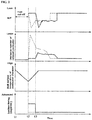
- FIG. 2 is a timing chart showing the transient state extending from the fuel cut-off control to a transient state following the fuel cut-off control termination in the present embodiment.
- the fuel cut-off condition is satisfied at time t1, and the fuel cut-off recovery condition is satisfied at time t2.
- the first fuel injection valve 11 resumes the fuel injection from the time t2.
- the rich spike operation by the first fuel injection valve 11 is performed at time t3 upon elapse of a predetermined delay time from time t2. Due to the rich spike, the exhaust gas air-fuel ratio (A / F) will assume a value on the rich side with respect to the stoichiometric air-fuel ratio from time t3. Further, in order to raise the wall surface temperature of the combustion chamber 2 that has be decreased by the implementation of fuel cut-off control, an ignition timing by a spark plug will be advanced than normal during a time period between time t2 and time t3.
- the normal ignition timing is represented by a so-called MBT (minimum advance for best torque) that is determined in accordance with an engine load and an engine speed. That is, during a time period between time t2 and time t3, the ignition timing is advanced by a predetermined ignition advance correction amount than MBT that is indicated by a broken line (optimum ignition timing) in FIG. 2 .
- MBT minimum advance for best torque
- the exhaust gas air-fuel ratio will assume a value on the rich side with respect to the stoichiometric air-fuel ratio as shown by a broken line in FIG. 2 .
- the rich spike is carried out at a cold combustion chamber 2 immediately after the fuel cut-off, the amount of fuel injected into the combustion chamber 2 and adhered to the piston 9 and the like is increased.
- the number of exhaust particles contained in emission will increase, as shown by the broken line in FIG. 2 .
- the wall surface temperature of the combustion chamber 2 may be previously raised before the implementation of rich spike operation. Therefore, it is possible to suppress the discharge number of the exhaust particles significantly as indicated by a solid line in FIG. 2 .
- the delay time is configured to be longer, as the time required from the time t1 to a time in which the fuel cut-off recovery condition is satisfied is longer, i.e., when the count of a fuel cut-off period counter is larger which counts a time at regular intervals from time t1 until the fuel cut recovery condition will be established.
- the ignition timing advance correction amount is configured to be larger, as the time required from the time t1 to a time in which the fuel cut-off recovery condition is satisfied is longer, i.e., when the count of the fuel cut-off period counter which counts the time at regular intervals from time t1 until the fuel cut recovery condition will be established is larger.
- the reason why the above delay time and the ignition timing advance correction amount are set as described above is because the temperature of the combustion chamber 2 is decreased as the immediately precedent fuel cut-off operation is longer so that the amount of fuel adhering to the piston 9 and the like, which has been injected during the fuel injection recovery from the first fuel injection valve 11, tends to increase.
- the higher the fuel cut-off period counter counts the delay time will be set longer. Also, the ignition timing advance correction amount will be set larger as the fuel cut-off counter counts higher. Thus, it is possible to hold the wall surface temperature of the combustion chamber 2 reliably high before the start of the rich spike.
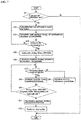
- FIG. 3 is a flowchart showing a flow of control regarding the rich spike pertaining to the present embodiment.
- step S1 it is determined whether or not the fuel cut-off condition is met. When the fuel cut-off condition is satisfied, control proceeds to step S2. When the fuel cut-off condition is not satisfied, the present routine ends.
- step S2 the fuel cut-off period counter (FCTCNT) is operated.
- step S3 it is determined whether or not the fuel cut-off is terminated. In other words, it is determined whether or not the fuel cut-off recovery condition is satisfied. When the fuel cut-off recovery condition is satisfied, control proceeds to step S4. Unless the fuel cut-off recovery condition is satisfied, control proceeds to step S2A.
- a delay time is calculated extending from resumption of fuel injection from the first injection valve in response to establishment of the fuel cut-off recovery condition to implementation of the rich spike.
- the delay time is calculated by using the delay time calculation map shown in FIG. 4 , for example so as to be longer as the fuel cut-off period counter (FCTCNT) counts higher.
- the ignition timing advance correction amount (CCANAD) which is the amount of correction of the ignition timing during a time period from resumption of fuel injection from the first injection valve in response to establishment of the fuel cut-off recovery condition to implementation of the rich spike.
- the advance angle correction amount is calculated using an ignition timing correction amount calculation map shown in FIG. 5 , for example. The higher the fuel cut-off period counter (FCTCNT) counts, the larger the ignition timing correction amount.
- step S6 it is determined whether or not the operating condition is in a high-load operating state. Control proceeds to S7 in the high-load operating state, whereas control proceeds to S8 if not in high-load operating state. For example, when the depression amount of the accelerator pedal is equal to or greater than a predetermined amount, it is determined that the internal combustion engine 1 is a high-load operating state. In step S7, the ignition timing advance correction by using the ignition timing advance angle correction amount will be prohibited. In step S8, by using the ignition timing advance correction amount calculated in step S5, the ignition timing will be advanced.
- step S9 it is determined whether or not a delay time (TFCRD), which has been calculated in step S4 after the fuel cut-off control ends, has elapsed.
- TFCRD delay time
- step S10 the ignition timing advance correction using an ignition timing advance correction amount (CCANAD) calculated in step S5 is terminated.
- step S11 the rich spike operation is performed.
- the delay time may be set in accordance with a wall surface temperature of the combustion chamber 2 during a fuel cut-off control, thus not corresponding to the time extending from time t1 to establishment of fuel cut-off recovery condition.
- the wall surface temperature (CCWTEMP) of the combustion chamber may be estimated using a detection signal of a water temperature sensor 24 and/or an oil temperature sensor 25.
- the delay time (TFCRD) is calculated by using the delay time calculation map shown in FIG. 6 , for example.
- FIG. 7 is a flowchart showing a flow of control over the rich spike in which the delay time is set in accordance with the wall surface temperature of the combustion chamber 2.
- step S21 it is determined whether or not the fuel cut-off condition is met or established.
- control proceeds to step S22.
- the fuel cut-off condition is not established, the present routine ends.
- step S22 the fuel cut-off period counter (FCTCNT) is put in operation.
- step S23 the wall surface temperature of the combustion chamber 2 (TFCRD) is calculated.
- step S24 it is determined whether or not the fuel cut-off operation is terminated. That is, it is determined whether or not the fuel cut-off recovery condition is met. When the fuel cut-off recovery condition is met, control proceeds to step S25. When the fuel cut-off recovery condition is not met, control proceeds to step S22.
- step S25 the delay time (TFCRD) is calculated that extends from a time of establishment of the fuel cut-off recovery condition for recovery of the fuel injection of the first fuel injection valve 11 until implementation of the rich spike.
- the delay time (TFCRD) is calculated by using a delay time calculation map shown in FIG. 6 described above, and, as the wall temperature of the combustion chamber 2 (TFCRD) is lower, the delay time will be longer.
- the ignition timing advance correction amount (CCANAD) which is the amount of correction of the ignition timing during a period from a time of establishment of the fuel cut-off recovery condition to resume the fuel injection of the first fuel injection valve 11 to a time of implementation of the rich spike.
- the ignition timing advance amount (CCANAD) is, for example, calculated using the ignition timing correction amount calculation map shown in FIG 5 described above. As the fuel cut-off period counter (FCTCNT) counts higher, the ignition timing advance amount will be larger.
- step S27 it is determined whether or not the operating condition is in a high-load operation state.
- control proceeds to step S28.
- step S29 For example, when the depression amount of the accelerator pedal is equal to or greater than a predetermined amount, it is determined that the internal combustion engine 1 is a high-load operating state.
- step S28 correction of the ignition timing to the advance side by using the ignition timing advance angle correction amount is prohibited.
- step S29 with the ignition timing advance correction amount calculated in S26, advancing of the ignition timing is performed.
- step S30 it is determined whether the delay time (TFCRD) calculated in step S25 has elapsed after the fuel cut-off control ends.
- control proceeds to step S31.
- step S27 the ignition timing correction to the advance side using the ignition timing advance correction amount (CCANAD) calculated in S26 will ends.
- step S32 the rich spike operation is performed.
- the delay time may be calculated in consideration of both the wall surface temperature of the combustion chamber and the count of the fuel cut-off period counter.
- the delay time is set to be longer.
- the ignition timing advance correction amount when the fuel injection resumes after the fuel cut control ends may be calculated in consideration of the wall surface temperature of the combustion chamber only. Alternatively, it may be calculated in consideration of both the fuel cut-off period count and the wall temperature of combustion chamber. In the latter case, as the fuel cut-off period count is higher, and as the wall temperature of combustion chamber is lower, the ignition timing advance correction amount is set to be larger.
Landscapes
- Engineering & Computer Science (AREA)
- Chemical & Material Sciences (AREA)
- Combustion & Propulsion (AREA)
- Mechanical Engineering (AREA)
- General Engineering & Computer Science (AREA)
- Theoretical Computer Science (AREA)
- Signal Processing (AREA)
- Electrical Control Of Air Or Fuel Supplied To Internal-Combustion Engine (AREA)
- Combined Controls Of Internal Combustion Engines (AREA)
- Electrical Control Of Ignition Timing (AREA)
Abstract
Description
- The present invention relates to a vehicle control system for an internal combustion engine in which fuel is directly injected into a combustion chamber.
- In an internal combustion engine mounted on a vehicle, the so-called fuel cut-off operation is carried out to stop a fuel supply to a combustion chamber so as to improve fuel economy in operating conditions such as during a vehicle deceleration in which output is not required.
- For example, in
Patent Document 1, a technique is disclosed in which, when resuming fuel injection from a fuel cut-off state, a rich spike operation is performed that temporarily increases a fuel injection amount so that a catalyst that has been reduced in exhaust gas purification performance due to excess oxygen supplied during a fuel period will be recovered. - However, in the
Patent Document 1, the situation is not considered in which a wall temperature of the combustion chamber is lowered during the fuel cut-off operation. Therefore, when performing the rich spike operation when resuming the fuel injection from the fuel cut-off state, without the fuel being vaporized, the fuel tends to adhere to a wall surface of the combustion chamber thus exhibiting a decreased temperature. Thus, the number of the exhaust particulates in the exhaust gas will be increased. In other although recovery of the exhaust gas purification performance of the catalyst is by the rich spike, the number of the exhaust particulates discharged is increased. Therefore, there is a possibility that the overall exhaust performance is deteriorated. - Patent Document 1: Japanese Patent Application Publication No.
2009-162195A - A vehicle control system for an internal combustion engine according to the present invention has a fuel injection valve for injecting fuel directly into a combustion chamber.
- The vehicle control system performs a fuel cut-off when predetermined fuel cut-off condition is met during traveling of the vehicle to stop fuel injection from the fuel injection valve, and restarts or resumes the fuel injection from the fuel injection valve when a predetermined fuel cut-off recovery condition is met during the fuel cut-off.
- Then, when a predetermined time has elapsed after resuming the fuel injection from the fuel injection valve, a rich spike operation is performed that temporarily increases the fuel injection amount from the fuel injection valve.
- According to the present invention, it is possible to raise in advance the temperature of a wall surface of the combustion chamber, which is defined by such as a piston and a cylinder inner wall surface, when starting the rich spike operation. Thus, fuel adhesion to the wall surface of the combustion chamber is reduced during the rich spike operation. Therefore, it is possible to reduce the number of exhaust particles.
-
-
FIG. 1 is an explanatory diagram showing a schematic construction of an internal combustion engine to which the present invention is applied; -
FIG. 2 is a timing chart showing states extending from the fuel cut-off control to the rich spike operation following termination of the fuel cut-off; -
FIG. 3 is a flowchart showing a flow of control regarding the rich spike pertaining to the present invention; -
FIG. 4 is a delay time calculation map; -
FIG. 5 is an ignition timing correction amount calculation map; -
FIG. 6 is a delay time calculation map; and -
FIG. 7 is another flowchart showing a flow of control regarding the rich spike according to the present invention. - Below, a description is given of an embodiment of the present invention in detail with reference to the accompanying drawings.
FIG. 1 shows a schematic configuration of aninternal combustion engine 1 to which the present invention is applied. Note that theinternal combustion engine 1 uses gasoline as fuel, for example. - A
combustion chamber 2 of theinternal combustion engine 1 is connected to an intake passage 4 with an intake valve 3 interposed. Further, thecombustion chamber 2 is connected to anexhaust passage 6 with an exhaust valve 5 interposed. - In the intake passage 4, a
throttle valve 7 of electronic control type is disposed. On the upstream side of thethrottle valve 7, anair flow meter 8 is provided for detecting an intake air quantity. Detection signals of theair flow meter 8 are inputted to an ECU (engine control unit) 20. - On top of the
combustion chamber 2, aspark plug 10 is disposed so as to face apiston 9. In the side portion of acombustion chamber 2 on the intake passage side, a firstfuel injection valve 11 which injects fuel directly in thecombustion chamber 2 is arranged. - The fuel under a relatively high pressure is introduced into the first
fuel injection valve 11 via apressure regulator 12 pressurized by a high-pressure fuel pump (not shown). It is possible for thepressure regulator 12 to vary the pressure of the fuel (fuel pressure) supplied to the firstfuel injection valve 11 based on a control command from theECU 20. - A three-
way catalyst 13 is interposed in theexhaust passage 6. Further, in theexhaust passage 6, a first air-fuel ratio sensor 14 is disposed on the upstream side of the three-way catalyst 13, and a second air-fuel ratio sensor 15 is disposed on the downstream side of the three-way catalyst 13. The air-fuel ratio sensors - The ECU 20 incorporates a microcomputer and is configured to perform various controls of the
internal combustion engine 1 based on processing of signals from various sensors. The various sensors includes, in addition to theair flow meter 8, the first and second air-fuel ratio sensors 15 described above, anaccelerator opening sensor 21 for detecting the opening (depression amount) of an accelerator pedal operated by the driver, acrank angle sensor 22 for detecting an engine speed together with a crank angle of thecrankshaft 17, athrottle sensor 23 for detecting the opening degree of athrottle valve 7, awater temperature sensor 24 for detecting a cooling water temperature of theinternal combustion engine 1, anoil temperature sensor 25 for detecting a temperature of the engine oil, avehicle speed sensor 26 for detecting a vehicle speed, afuel pressure sensor 27 for detecting a fuel pressure supplied to the firstfuel injection valve 11, and the like. - Further, the
ECU 20, based on these detection signals, controls an injection amount and injection timing of the firstfuel injection valve 11, an ignition timing of thespark plug 10, and the opening degree of thethrottle valve 7. - Note that the
internal combustion engine 1 may have a second fuel injection valve disposed on the downstream side of thethrottle valve 7 for injecting fuel in the intake passage 4 for each cylinder to supply the fuel in thecombustion chamber 2 by a so-called port injection. - When a predetermined fuel cut-off condition is met or satisfied during deceleration of the vehicle, the ECU 20 performs a fuel cut-off control for stopping the fuel injection from the first
fuel injection valve 11 and the secondfuel injection valve 16. For example, the ECU 20 considers the fuel cut-off condition to be met and performs the fuel cut-off operation when the engine speed is at a predetermined fuel cut-off rotational speed or higher after the warm-up is complete and when thethrottle valve 7 is fully closed. Subsequently, during the fuel-cut control execution, upon a predetermined fuel cut-off recovery condition being met, theECU 20 resumes the fuel injection of the firstfuel injection valve 11. For example, during the fuel cut-off control, when the accelerator pedal is depressed and thethrottle valve 7 is no longer in a fully closed state, or when the engine speed falls to or less than the predetermined fuel cut-off recovery rotational speed without the accelerator pedal being depressed, the ECU 20 considers the fuel cut-off recovery condition to be met and terminates the fuel cut-off control. - When performing the fuel cut-off control, a relatively large amount of oxygen is supplied to the three-
way catalyst 13. In other words, the three-way catalyst 13 is supposed to adsorb large amounts of oxygen during the fuel cut-off control. Thus, there is a possibility that it is difficult to reduce NOx by removing oxygen from NOx in the exhaust gas when the fuel cut-off control ends. Therefore, in the present embodiment, when resuming the fuel injection control subsequent to the fuel cut-off control, by performing a rich spike in which the amount of fuel injection quantity injected from the firstfuel injection valve 11 is temporarily increased, regeneration of the exhaust gas purification ability (NOx reducing ability) of theoriginal catalyst 13 will be promoted. - It should be noted here that, during the fuel cut-off control, the temperature of the
combustion chamber 2, i.e., the temperature of apiston 9, cylinder inner wall surface, and the like has been decreased since combustion of theinternal combustion engine 1 is being stopped. Therefore, when the fuel cut-off control ends and fuel injection of the firstfuel injection valve 11 is subsequently resumed, the amount of fuel injected into thecombustion chamber 2 from the firstfuel injection valve 11 and adhering to thepiston 9 and the like is likely to be increased. Thus, there is a possibility that the discharge number of exhaust particles increases. - Further, when carrying out the rich spike operation at the same time as the satisfaction of the fuel cut-off recovery condition, although the exhaust gas purifying performance of the three-
way catalyst 13 may be recovered early, the adhesion amount of the fuel to thepiston 9 and the like is further increased by the rich spike. Thus, there is a possibility that the exhaust performance will be deteriorated as a whole. - Therefore, in the present embodiment, the rich spike operation is performed upon elapse of a predetermined delay time from a time in which the fuel cut-off recovery condition is satisfied. Note that the first
fuel injection valve 11 resumes the fuel injection during an intake stroke from a time in which the fuel cut-off recovery condition is satisfied. -
FIG. 2 is a timing chart showing the transient state extending from the fuel cut-off control to a transient state following the fuel cut-off control termination in the present embodiment. - In
FIG. 2 , the fuel cut-off condition is satisfied at time t1, and the fuel cut-off recovery condition is satisfied at time t2. The firstfuel injection valve 11 resumes the fuel injection from the time t2. The rich spike operation by the firstfuel injection valve 11 is performed at time t3 upon elapse of a predetermined delay time from time t2. Due to the rich spike, the exhaust gas air-fuel ratio (A / F) will assume a value on the rich side with respect to the stoichiometric air-fuel ratio from time t3. Further, in order to raise the wall surface temperature of thecombustion chamber 2 that has be decreased by the implementation of fuel cut-off control, an ignition timing by a spark plug will be advanced than normal during a time period between time t2 and time t3. The normal ignition timing is represented by a so-called MBT (minimum advance for best torque) that is determined in accordance with an engine load and an engine speed. That is, during a time period between time t2 and time t3, the ignition timing is advanced by a predetermined ignition advance correction amount than MBT that is indicated by a broken line (optimum ignition timing) inFIG. 2 . - If the rich spike is performed from time t2 in which the fuel injection of the first
fuel injection valve 11 is resumed, the exhaust gas air-fuel ratio will assume a value on the rich side with respect to the stoichiometric air-fuel ratio as shown by a broken line inFIG. 2 . In this case, because the rich spike is carried out at acold combustion chamber 2 immediately after the fuel cut-off, the amount of fuel injected into thecombustion chamber 2 and adhered to thepiston 9 and the like is increased. Thus, the number of exhaust particles contained in emission will increase, as shown by the broken line inFIG. 2 . - On the contrary, when the rich spike operation of the first
fuel injection valve 11 is delayed from time t2 to time t3 after elapse of the delay time, the wall surface temperature of thecombustion chamber 2 may be previously raised before the implementation of rich spike operation. Therefore, it is possible to suppress the discharge number of the exhaust particles significantly as indicated by a solid line inFIG. 2 . - Further, by correcting the ignition timing to the advance side during the time period between time t2 and time t3, increase in wall surface temperature of the
combustion chamber 2 is accelerated prior to the implementation of rich spike. Therefore, when carrying out the rich spike, the fuel adhesion to the wall surface of thecombustion chamber 2 can be further reduced. - In addition, the delay time is configured to be longer, as the time required from the time t1 to a time in which the fuel cut-off recovery condition is satisfied is longer, i.e., when the count of a fuel cut-off period counter is larger which counts a time at regular intervals from time t1 until the fuel cut recovery condition will be established.
- Further, the ignition timing advance correction amount is configured to be larger, as the time required from the time t1 to a time in which the fuel cut-off recovery condition is satisfied is longer, i.e., when the count of the fuel cut-off period counter which counts the time at regular intervals from time t1 until the fuel cut recovery condition will be established is larger.
- The reason why the above delay time and the ignition timing advance correction amount are set as described above is because the temperature of the
combustion chamber 2 is decreased as the immediately precedent fuel cut-off operation is longer so that the amount of fuel adhering to thepiston 9 and the like, which has been injected during the fuel injection recovery from the firstfuel injection valve 11, tends to increase. - Therefore, the higher the fuel cut-off period counter counts, the delay time will be set longer. Also, the ignition timing advance correction amount will be set larger as the fuel cut-off counter counts higher. Thus, it is possible to hold the wall surface temperature of the
combustion chamber 2 reliably high before the start of the rich spike. -
FIG. 3 is a flowchart showing a flow of control regarding the rich spike pertaining to the present embodiment. In step S1, it is determined whether or not the fuel cut-off condition is met. When the fuel cut-off condition is satisfied, control proceeds to step S2. When the fuel cut-off condition is not satisfied, the present routine ends. In step S2, the fuel cut-off period counter (FCTCNT) is operated. In step S3, it is determined whether or not the fuel cut-off is terminated. In other words, it is determined whether or not the fuel cut-off recovery condition is satisfied. When the fuel cut-off recovery condition is satisfied, control proceeds to step S4. Unless the fuel cut-off recovery condition is satisfied, control proceeds to step S2A. In step S4, a delay time (TFCRD) is calculated extending from resumption of fuel injection from the first injection valve in response to establishment of the fuel cut-off recovery condition to implementation of the rich spike. The delay time (TFCRD) is calculated by using the delay time calculation map shown inFIG. 4 , for example so as to be longer as the fuel cut-off period counter (FCTCNT) counts higher. In step S5, the ignition timing advance correction amount (CCANAD) which is the amount of correction of the ignition timing during a time period from resumption of fuel injection from the first injection valve in response to establishment of the fuel cut-off recovery condition to implementation of the rich spike. The advance angle correction amount (CCANAD) is calculated using an ignition timing correction amount calculation map shown inFIG. 5 , for example. The higher the fuel cut-off period counter (FCTCNT) counts, the larger the ignition timing correction amount. - In step S6, it is determined whether or not the operating condition is in a high-load operating state. Control proceeds to S7 in the high-load operating state, whereas control proceeds to S8 if not in high-load operating state. For example, when the depression amount of the accelerator pedal is equal to or greater than a predetermined amount, it is determined that the
internal combustion engine 1 is a high-load operating state. In step S7, the ignition timing advance correction by using the ignition timing advance angle correction amount will be prohibited. In step S8, by using the ignition timing advance correction amount calculated in step S5, the ignition timing will be advanced. - In step S9, it is determined whether or not a delay time (TFCRD), which has been calculated in step S4 after the fuel cut-off control ends, has elapsed. When it is determined to be elapsed, control proceeds to step S10. If not, control proceeds to step S6. In step S10, the ignition timing advance correction using an ignition timing advance correction amount (CCANAD) calculated in step S5 is terminated. In step S11, the rich spike operation is performed.
- Thus, when the operating state of the
internal combustion engine 1 is in a high-load operating state, correction of the ignition timing to the advance side is prohibited. Thus, it is possible to suppress occurrence of knocking at the time of recovery of fuel injection of the firstfuel injection valve 11 in response to a fuel cut-off recovery condition being met. - Further, the delay time may be set in accordance with a wall surface temperature of the
combustion chamber 2 during a fuel cut-off control, thus not corresponding to the time extending from time t1 to establishment of fuel cut-off recovery condition. - For example, the wall surface temperature (CCWTEMP) of the combustion chamber may be estimated using a detection signal of a
water temperature sensor 24 and/or anoil temperature sensor 25. The lower the wall temperature of the combustion chamber 2 (CCWTEMP) is estimated, the longer the delay time will be set. In this case, the delay time (TFCRD) is calculated by using the delay time calculation map shown inFIG. 6 , for example. The lower the wall surface temperature (CCWTEMP) is estimated, the longer the delay time assumes. - In other words, by setting the delay time in accordance with the wall surface temperature of the
combustion chamber 2 during the fuel cut-off control, it is possible to raise the wall temperature of thecombustion chamber 2 in advance before the start of the rich spike. Thus, it is possible to reduce adhesion of fuel to the wall surface of the combustion chamber at that time. -
FIG. 7 is a flowchart showing a flow of control over the rich spike in which the delay time is set in accordance with the wall surface temperature of thecombustion chamber 2. - In step S21, it is determined whether or not the fuel cut-off condition is met or established. When the fuel cut condition is established, control proceeds to step S22. When the fuel cut-off condition is not established, the present routine ends. In step S22, the fuel cut-off period counter (FCTCNT) is put in operation. In step S23, the wall surface temperature of the combustion chamber 2 (TFCRD) is calculated. In step S24, it is determined whether or not the fuel cut-off operation is terminated. That is, it is determined whether or not the fuel cut-off recovery condition is met. When the fuel cut-off recovery condition is met, control proceeds to step S25. When the fuel cut-off recovery condition is not met, control proceeds to step S22. In step S25, the delay time (TFCRD) is calculated that extends from a time of establishment of the fuel cut-off recovery condition for recovery of the fuel injection of the first
fuel injection valve 11 until implementation of the rich spike. The delay time (TFCRD) is calculated by using a delay time calculation map shown inFIG. 6 described above, and, as the wall temperature of the combustion chamber 2 (TFCRD) is lower, the delay time will be longer. In step S26, the ignition timing advance correction amount (CCANAD) which is the amount of correction of the ignition timing during a period from a time of establishment of the fuel cut-off recovery condition to resume the fuel injection of the firstfuel injection valve 11 to a time of implementation of the rich spike. The ignition timing advance amount (CCANAD) is, for example, calculated using the ignition timing correction amount calculation map shown inFIG 5 described above. As the fuel cut-off period counter (FCTCNT) counts higher, the ignition timing advance amount will be larger. - In step S27, it is determined whether or not the operating condition is in a high-load operation state. When determined in the high-load operating state, control proceeds to step S28. When not in the high-load operating state, control proceeds to step S29. For example, when the depression amount of the accelerator pedal is equal to or greater than a predetermined amount, it is determined that the
internal combustion engine 1 is a high-load operating state. In step S28, correction of the ignition timing to the advance side by using the ignition timing advance angle correction amount is prohibited. In step S29, with the ignition timing advance correction amount calculated in S26, advancing of the ignition timing is performed. - In step S30, it is determined whether the delay time (TFCRD) calculated in step S25 has elapsed after the fuel cut-off control ends. When the delay time has elapsed, control proceeds to step S31. When not, control proceeds to step S27. In step S31, the ignition timing correction to the advance side using the ignition timing advance correction amount (CCANAD) calculated in S26 will ends. In step S32, the rich spike operation is performed.
- Note that, when performing rich spike, it is advantageous to suppress increase in the discharge number of the exhaust particulates by adjusting the exhaust gas air-fuel ratio larger than 12.5 and smaller than 13.
- Further, the delay time may be calculated in consideration of both the wall surface temperature of the combustion chamber and the count of the fuel cut-off period counter.
- In this case, as the fuel cut-off period counter counts higher, and as the wall surface temperature of the combustion chamber wall is lower, the delay time is set to be longer.
- In addition, the ignition timing advance correction amount when the fuel injection resumes after the fuel cut control ends may be calculated in consideration of the wall surface temperature of the combustion chamber only. Alternatively, it may be calculated in consideration of both the fuel cut-off period count and the wall temperature of combustion chamber. In the latter case, as the fuel cut-off period count is higher, and as the wall temperature of combustion chamber is lower, the ignition timing advance correction amount is set to be larger.
Claims (6)
- A vehicle control system for an internal combustion engine having a fuel injection valve for injecting fuel directly into a combustion chamber, the vehicle control system being configured to perform a fuel cut-off when a predetermined fuel cut-off condition is met during travel of the vehicle to thereby stop fuel injection from the fuel injection valve, and configured to resume the fuel injection from the fuel injection valve when a predetermined fuel cut-off recovery condition is met during the fuel cut-off, the vehicle control system being further configured, upon elapse of a predetermined time after resuming the fuel injection from the fuel injection valve, to perform a rich spike that temporarily increases the fuel injection amount from the fuel injection valve.
- The vehicle control system according to claim 1, wherein, as a fuel cut-off period is longer, the predetermined time is configured to be longer.
- The vehicle control system according to claim 1, wherein, as a wall temperature of the combustion chamber is lower, the predetermined time is configured to be longer.
- The vehicle control system according to any one of claims 1 to 3, wherein, during a period between when the fuel cut-off ends and when the predetermined time has elapsed, the ignition timing is configured to be advanced.
- The vehicle control system according to claim 4, wherein, as the fuel cut-off period is longer, the ignition timing advance amount is configured to be larger.
- The vehicle control system according to either claim 4 or 5, when the internal combustion engine is in a high-load operating state, the ignition timing is prohibited from being advanced from the fuel cut-off termination until elapse of the predetermined time.
Applications Claiming Priority (1)
| Application Number | Priority Date | Filing Date | Title |
|---|---|---|---|
| PCT/JP2014/081815 WO2016088191A1 (en) | 2014-12-02 | 2014-12-02 | Controlling device for internal combustion engines |
Publications (3)
| Publication Number | Publication Date |
|---|---|
| EP3184786A1 true EP3184786A1 (en) | 2017-06-28 |
| EP3184786A4 EP3184786A4 (en) | 2017-10-04 |
| EP3184786B1 EP3184786B1 (en) | 2018-10-10 |
Family
ID=56091170
Family Applications (1)
| Application Number | Title | Priority Date | Filing Date |
|---|---|---|---|
| EP14907603.6A Not-in-force EP3184786B1 (en) | 2014-12-02 | 2014-12-02 | Controlling device for internal combustion engines |
Country Status (5)
| Country | Link |
|---|---|
| US (1) | US9885304B2 (en) |
| EP (1) | EP3184786B1 (en) |
| JP (1) | JP6156593B2 (en) |
| CN (1) | CN107002570B (en) |
| WO (1) | WO2016088191A1 (en) |
Families Citing this family (9)
| Publication number | Priority date | Publication date | Assignee | Title |
|---|---|---|---|---|
| CN112005002B (en) * | 2018-04-26 | 2022-12-23 | 日产自动车株式会社 | Control method and control device for internal combustion engine |
| JP7020338B2 (en) * | 2018-08-07 | 2022-02-16 | トヨタ自動車株式会社 | Internal combustion engine control device |
| JP2020133549A (en) * | 2019-02-22 | 2020-08-31 | 株式会社デンソー | Control device |
| US11519352B2 (en) | 2019-08-26 | 2022-12-06 | Kohler Co. | Spark ignited single cylinder engine derate for overheat |
| US11799342B2 (en) | 2020-02-20 | 2023-10-24 | Kohler Co. | Printed circuit board electrical machine |
| JP7123093B2 (en) * | 2020-07-03 | 2022-08-22 | 本田技研工業株式会社 | Control device for internal combustion engine |
| JP2023161331A (en) * | 2022-04-25 | 2023-11-07 | トヨタ自動車株式会社 | Internal combustion engine exhaust purification device |
| JP7731321B2 (en) * | 2022-05-17 | 2025-08-29 | Astemo株式会社 | Internal combustion engine control device |
| JP7768095B2 (en) * | 2022-10-31 | 2025-11-12 | トヨタ自動車株式会社 | Control device for internal combustion engine |
Family Cites Families (28)
| Publication number | Priority date | Publication date | Assignee | Title |
|---|---|---|---|---|
| JPH05141293A (en) * | 1991-11-21 | 1993-06-08 | Daihatsu Motor Co Ltd | Air fuel ratio correcting method |
| JP3132357B2 (en) * | 1995-09-07 | 2001-02-05 | トヨタ自動車株式会社 | Control device for internal combustion engine assisted by electric motor |
| JP3123474B2 (en) * | 1997-07-28 | 2001-01-09 | トヨタ自動車株式会社 | Exhaust gas purification device for internal combustion engine |
| JPH11257130A (en) * | 1998-03-17 | 1999-09-21 | Suzuki Motor Corp | Fuel control device for internal combustion engine |
| JP3417299B2 (en) * | 1998-06-19 | 2003-06-16 | トヨタ自動車株式会社 | Engine control amount setting method and control device for internal combustion engine |
| JP3680244B2 (en) * | 1999-02-12 | 2005-08-10 | トヨタ自動車株式会社 | Adsorption amount calculation device for unburned fuel component adsorbent of internal combustion engine |
| JP3759567B2 (en) * | 1999-10-14 | 2006-03-29 | 株式会社デンソー | Catalyst degradation state detection device |
| JP4275330B2 (en) * | 2001-06-28 | 2009-06-10 | 三菱電機株式会社 | Air-fuel ratio control device for internal combustion engine |
| JP2004108183A (en) * | 2002-09-17 | 2004-04-08 | Denso Corp | Air-fuel ratio control device for internal combustion engine |
| JP4159918B2 (en) * | 2003-04-16 | 2008-10-01 | 本田技研工業株式会社 | Fuel cut control device for compression ignition type internal combustion engine |
| JP4511954B2 (en) * | 2005-01-12 | 2010-07-28 | トヨタ自動車株式会社 | Fuel injection control device for internal combustion engine |
| JP2007285156A (en) * | 2006-04-13 | 2007-11-01 | Toyota Motor Corp | Exhaust gas purification device for internal combustion engine |
| JP4264760B2 (en) * | 2007-04-09 | 2009-05-20 | 三菱自動車工業株式会社 | Exhaust gas purification device for internal combustion engine |
| JP4367525B2 (en) * | 2007-05-22 | 2009-11-18 | トヨタ自動車株式会社 | Exhaust purification device for internal combustion engine and exhaust control device for internal combustion engine |
| JP5104323B2 (en) | 2008-01-10 | 2012-12-19 | 日産自動車株式会社 | Engine air-fuel ratio control apparatus and air-fuel ratio control method |
| JP4633820B2 (en) * | 2008-05-21 | 2011-02-16 | トヨタ自動車株式会社 | Control device for internal combustion engine |
| JP5418675B2 (en) * | 2010-06-16 | 2014-02-19 | トヨタ自動車株式会社 | Fuel control device for internal combustion engine |
| JP5261470B2 (en) * | 2010-06-25 | 2013-08-14 | 本田技研工業株式会社 | Air-fuel ratio control device for internal combustion engine |
| JP5396430B2 (en) * | 2011-05-23 | 2014-01-22 | 日立オートモティブシステムズ株式会社 | In-cylinder injection internal combustion engine control device |
| WO2013030949A1 (en) * | 2011-08-30 | 2013-03-07 | トヨタ自動車株式会社 | Exhaust gas purification device for internal combustion engine |
| JP5287959B2 (en) * | 2011-09-26 | 2013-09-11 | トヨタ自動車株式会社 | Control device for internal combustion engine |
| WO2013061697A1 (en) * | 2011-10-24 | 2013-05-02 | 日産自動車株式会社 | Control device for spark ignition internal combustion engine |
| US9309817B2 (en) * | 2011-11-28 | 2016-04-12 | Nissan Motor Co., Ltd. | Fuel cut control device and fuel cut control method for internal combustion engine |
| US8989989B2 (en) * | 2012-09-13 | 2015-03-24 | GM Global Technology Operations LLC | System and method for controlling fuel injection in an engine based on piston temperature |
| CN104956048B (en) * | 2013-01-29 | 2016-10-26 | 日产自动车株式会社 | The control device of variable compression ratio internal combustion engine and control method |
| US9897028B2 (en) * | 2013-06-26 | 2018-02-20 | Toyota Jidosha Kabushiki Kaisha | Diagnosis system of internal combustion engine |
| JP6288419B2 (en) * | 2013-12-26 | 2018-03-07 | 三菱自動車工業株式会社 | Engine fuel injection control device |
| JP6256240B2 (en) * | 2014-07-28 | 2018-01-10 | トヨタ自動車株式会社 | Control device for internal combustion engine |
-
2014
- 2014-12-02 CN CN201480083810.6A patent/CN107002570B/en not_active Expired - Fee Related
- 2014-12-02 JP JP2016562117A patent/JP6156593B2/en not_active Expired - Fee Related
- 2014-12-02 EP EP14907603.6A patent/EP3184786B1/en not_active Not-in-force
- 2014-12-02 US US15/519,902 patent/US9885304B2/en not_active Expired - Fee Related
- 2014-12-02 WO PCT/JP2014/081815 patent/WO2016088191A1/en not_active Ceased
Also Published As
| Publication number | Publication date |
|---|---|
| JPWO2016088191A1 (en) | 2017-04-27 |
| CN107002570A (en) | 2017-08-01 |
| EP3184786B1 (en) | 2018-10-10 |
| CN107002570B (en) | 2018-07-24 |
| US9885304B2 (en) | 2018-02-06 |
| EP3184786A4 (en) | 2017-10-04 |
| WO2016088191A1 (en) | 2016-06-09 |
| JP6156593B2 (en) | 2017-07-05 |
| US20170350337A1 (en) | 2017-12-07 |
Similar Documents
| Publication | Publication Date | Title |
|---|---|---|
| EP3184786B1 (en) | Controlling device for internal combustion engines | |
| JP6183565B2 (en) | Control device and control method for internal combustion engine | |
| US20100006078A1 (en) | Engine controller | |
| JP5796635B2 (en) | Fuel cut control device and fuel cut control method for internal combustion engine | |
| EP2527621B1 (en) | Control device for internal combustion engine | |
| US9470169B2 (en) | Control device for internal combustion engine | |
| JP6187709B2 (en) | Control device for internal combustion engine | |
| JP5273310B2 (en) | Control device for internal combustion engine | |
| JP6260718B2 (en) | Control device for internal combustion engine | |
| JP2011157906A (en) | Control device for internal combustion engine | |
| JP2016147562A (en) | Control device for internal combustion engine | |
| JP2012159003A (en) | Method for controlling internal combustion engine | |
| JP2012251510A (en) | Internal combustion engine control device | |
| JP2009203826A (en) | Fuel injection control device for internal combustion engine | |
| JP2008267175A (en) | Control device for internal combustion engine | |
| JP2011185189A (en) | Vehicle control system | |
| JP2014206075A (en) | Control device for internal combustion engine |
Legal Events
| Date | Code | Title | Description |
|---|---|---|---|
| STAA | Information on the status of an ep patent application or granted ep patent |
Free format text: STATUS: THE INTERNATIONAL PUBLICATION HAS BEEN MADE |
|
| PUAI | Public reference made under article 153(3) epc to a published international application that has entered the european phase |
Free format text: ORIGINAL CODE: 0009012 |
|
| STAA | Information on the status of an ep patent application or granted ep patent |
Free format text: STATUS: REQUEST FOR EXAMINATION WAS MADE |
|
| 17P | Request for examination filed |
Effective date: 20170324 |
|
| AK | Designated contracting states |
Kind code of ref document: A1 Designated state(s): AL AT BE BG CH CY CZ DE DK EE ES FI FR GB GR HR HU IE IS IT LI LT LU LV MC MK MT NL NO PL PT RO RS SE SI SK SM TR |
|
| AX | Request for extension of the european patent |
Extension state: BA ME |
|
| A4 | Supplementary search report drawn up and despatched |
Effective date: 20170905 |
|
| RIC1 | Information provided on ipc code assigned before grant |
Ipc: F02P 5/15 20060101ALI20170830BHEP Ipc: F02D 41/12 20060101ALI20170830BHEP Ipc: F02D 29/02 20060101ALI20170830BHEP Ipc: F02D 41/02 20060101ALI20170830BHEP Ipc: F02D 43/00 20060101ALI20170830BHEP Ipc: F02D 45/00 20060101ALI20170830BHEP Ipc: F02D 41/04 20060101AFI20170830BHEP |
|
| DAX | Request for extension of the european patent (deleted) | ||
| GRAP | Despatch of communication of intention to grant a patent |
Free format text: ORIGINAL CODE: EPIDOSNIGR1 |
|
| STAA | Information on the status of an ep patent application or granted ep patent |
Free format text: STATUS: GRANT OF PATENT IS INTENDED |
|
| INTG | Intention to grant announced |
Effective date: 20180629 |
|
| GRAS | Grant fee paid |
Free format text: ORIGINAL CODE: EPIDOSNIGR3 |
|
| GRAA | (expected) grant |
Free format text: ORIGINAL CODE: 0009210 |
|
| STAA | Information on the status of an ep patent application or granted ep patent |
Free format text: STATUS: THE PATENT HAS BEEN GRANTED |
|
| AK | Designated contracting states |
Kind code of ref document: B1 Designated state(s): AL AT BE BG CH CY CZ DE DK EE ES FI FR GB GR HR HU IE IS IT LI LT LU LV MC MK MT NL NO PL PT RO RS SE SI SK SM TR |
|
| REG | Reference to a national code |
Ref country code: GB Ref legal event code: FG4D |
|
| REG | Reference to a national code |
Ref country code: CH Ref legal event code: EP Ref country code: AT Ref legal event code: REF Ref document number: 1051520 Country of ref document: AT Kind code of ref document: T Effective date: 20181015 |
|
| REG | Reference to a national code |
Ref country code: IE Ref legal event code: FG4D |
|
| REG | Reference to a national code |
Ref country code: DE Ref legal event code: R096 Ref document number: 602014034105 Country of ref document: DE |
|
| REG | Reference to a national code |
Ref country code: NL Ref legal event code: MP Effective date: 20181010 |
|
| REG | Reference to a national code |
Ref country code: LT Ref legal event code: MG4D |
|
| REG | Reference to a national code |
Ref country code: AT Ref legal event code: MK05 Ref document number: 1051520 Country of ref document: AT Kind code of ref document: T Effective date: 20181010 |
|
| PG25 | Lapsed in a contracting state [announced via postgrant information from national office to epo] |
Ref country code: NL Free format text: LAPSE BECAUSE OF FAILURE TO SUBMIT A TRANSLATION OF THE DESCRIPTION OR TO PAY THE FEE WITHIN THE PRESCRIBED TIME-LIMIT Effective date: 20181010 |
|
| PG25 | Lapsed in a contracting state [announced via postgrant information from national office to epo] |
Ref country code: LT Free format text: LAPSE BECAUSE OF FAILURE TO SUBMIT A TRANSLATION OF THE DESCRIPTION OR TO PAY THE FEE WITHIN THE PRESCRIBED TIME-LIMIT Effective date: 20181010 Ref country code: NO Free format text: LAPSE BECAUSE OF FAILURE TO SUBMIT A TRANSLATION OF THE DESCRIPTION OR TO PAY THE FEE WITHIN THE PRESCRIBED TIME-LIMIT Effective date: 20190110 Ref country code: HR Free format text: LAPSE BECAUSE OF FAILURE TO SUBMIT A TRANSLATION OF THE DESCRIPTION OR TO PAY THE FEE WITHIN THE PRESCRIBED TIME-LIMIT Effective date: 20181010 Ref country code: BG Free format text: LAPSE BECAUSE OF FAILURE TO SUBMIT A TRANSLATION OF THE DESCRIPTION OR TO PAY THE FEE WITHIN THE PRESCRIBED TIME-LIMIT Effective date: 20190110 Ref country code: AT Free format text: LAPSE BECAUSE OF FAILURE TO SUBMIT A TRANSLATION OF THE DESCRIPTION OR TO PAY THE FEE WITHIN THE PRESCRIBED TIME-LIMIT Effective date: 20181010 Ref country code: PL Free format text: LAPSE BECAUSE OF FAILURE TO SUBMIT A TRANSLATION OF THE DESCRIPTION OR TO PAY THE FEE WITHIN THE PRESCRIBED TIME-LIMIT Effective date: 20181010 Ref country code: LV Free format text: LAPSE BECAUSE OF FAILURE TO SUBMIT A TRANSLATION OF THE DESCRIPTION OR TO PAY THE FEE WITHIN THE PRESCRIBED TIME-LIMIT Effective date: 20181010 Ref country code: FI Free format text: LAPSE BECAUSE OF FAILURE TO SUBMIT A TRANSLATION OF THE DESCRIPTION OR TO PAY THE FEE WITHIN THE PRESCRIBED TIME-LIMIT Effective date: 20181010 Ref country code: ES Free format text: LAPSE BECAUSE OF FAILURE TO SUBMIT A TRANSLATION OF THE DESCRIPTION OR TO PAY THE FEE WITHIN THE PRESCRIBED TIME-LIMIT Effective date: 20181010 Ref country code: IS Free format text: LAPSE BECAUSE OF FAILURE TO SUBMIT A TRANSLATION OF THE DESCRIPTION OR TO PAY THE FEE WITHIN THE PRESCRIBED TIME-LIMIT Effective date: 20190210 |
|
| PG25 | Lapsed in a contracting state [announced via postgrant information from national office to epo] |
Ref country code: GR Free format text: LAPSE BECAUSE OF FAILURE TO SUBMIT A TRANSLATION OF THE DESCRIPTION OR TO PAY THE FEE WITHIN THE PRESCRIBED TIME-LIMIT Effective date: 20190111 Ref country code: PT Free format text: LAPSE BECAUSE OF FAILURE TO SUBMIT A TRANSLATION OF THE DESCRIPTION OR TO PAY THE FEE WITHIN THE PRESCRIBED TIME-LIMIT Effective date: 20190210 Ref country code: RS Free format text: LAPSE BECAUSE OF FAILURE TO SUBMIT A TRANSLATION OF THE DESCRIPTION OR TO PAY THE FEE WITHIN THE PRESCRIBED TIME-LIMIT Effective date: 20181010 Ref country code: SE Free format text: LAPSE BECAUSE OF FAILURE TO SUBMIT A TRANSLATION OF THE DESCRIPTION OR TO PAY THE FEE WITHIN THE PRESCRIBED TIME-LIMIT Effective date: 20181010 Ref country code: AL Free format text: LAPSE BECAUSE OF FAILURE TO SUBMIT A TRANSLATION OF THE DESCRIPTION OR TO PAY THE FEE WITHIN THE PRESCRIBED TIME-LIMIT Effective date: 20181010 |
|
| REG | Reference to a national code |
Ref country code: DE Ref legal event code: R097 Ref document number: 602014034105 Country of ref document: DE |
|
| PG25 | Lapsed in a contracting state [announced via postgrant information from national office to epo] |
Ref country code: DK Free format text: LAPSE BECAUSE OF FAILURE TO SUBMIT A TRANSLATION OF THE DESCRIPTION OR TO PAY THE FEE WITHIN THE PRESCRIBED TIME-LIMIT Effective date: 20181010 Ref country code: CZ Free format text: LAPSE BECAUSE OF FAILURE TO SUBMIT A TRANSLATION OF THE DESCRIPTION OR TO PAY THE FEE WITHIN THE PRESCRIBED TIME-LIMIT Effective date: 20181010 Ref country code: IT Free format text: LAPSE BECAUSE OF FAILURE TO SUBMIT A TRANSLATION OF THE DESCRIPTION OR TO PAY THE FEE WITHIN THE PRESCRIBED TIME-LIMIT Effective date: 20181010 |
|
| REG | Reference to a national code |
Ref country code: CH Ref legal event code: PL |
|
| PLBE | No opposition filed within time limit |
Free format text: ORIGINAL CODE: 0009261 |
|
| STAA | Information on the status of an ep patent application or granted ep patent |
Free format text: STATUS: NO OPPOSITION FILED WITHIN TIME LIMIT |
|
| PG25 | Lapsed in a contracting state [announced via postgrant information from national office to epo] |
Ref country code: MC Free format text: LAPSE BECAUSE OF FAILURE TO SUBMIT A TRANSLATION OF THE DESCRIPTION OR TO PAY THE FEE WITHIN THE PRESCRIBED TIME-LIMIT Effective date: 20181010 Ref country code: SK Free format text: LAPSE BECAUSE OF FAILURE TO SUBMIT A TRANSLATION OF THE DESCRIPTION OR TO PAY THE FEE WITHIN THE PRESCRIBED TIME-LIMIT Effective date: 20181010 Ref country code: LU Free format text: LAPSE BECAUSE OF NON-PAYMENT OF DUE FEES Effective date: 20181202 Ref country code: EE Free format text: LAPSE BECAUSE OF FAILURE TO SUBMIT A TRANSLATION OF THE DESCRIPTION OR TO PAY THE FEE WITHIN THE PRESCRIBED TIME-LIMIT Effective date: 20181010 Ref country code: SM Free format text: LAPSE BECAUSE OF FAILURE TO SUBMIT A TRANSLATION OF THE DESCRIPTION OR TO PAY THE FEE WITHIN THE PRESCRIBED TIME-LIMIT Effective date: 20181010 Ref country code: RO Free format text: LAPSE BECAUSE OF FAILURE TO SUBMIT A TRANSLATION OF THE DESCRIPTION OR TO PAY THE FEE WITHIN THE PRESCRIBED TIME-LIMIT Effective date: 20181010 |
|
| 26N | No opposition filed |
Effective date: 20190711 |
|
| REG | Reference to a national code |
Ref country code: IE Ref legal event code: MM4A |
|
| REG | Reference to a national code |
Ref country code: BE Ref legal event code: MM Effective date: 20181231 |
|
| PG25 | Lapsed in a contracting state [announced via postgrant information from national office to epo] |
Ref country code: SI Free format text: LAPSE BECAUSE OF FAILURE TO SUBMIT A TRANSLATION OF THE DESCRIPTION OR TO PAY THE FEE WITHIN THE PRESCRIBED TIME-LIMIT Effective date: 20181010 Ref country code: IE Free format text: LAPSE BECAUSE OF NON-PAYMENT OF DUE FEES Effective date: 20181202 |
|
| PG25 | Lapsed in a contracting state [announced via postgrant information from national office to epo] |
Ref country code: BE Free format text: LAPSE BECAUSE OF NON-PAYMENT OF DUE FEES Effective date: 20181231 |
|
| PG25 | Lapsed in a contracting state [announced via postgrant information from national office to epo] |
Ref country code: CH Free format text: LAPSE BECAUSE OF NON-PAYMENT OF DUE FEES Effective date: 20181231 Ref country code: LI Free format text: LAPSE BECAUSE OF NON-PAYMENT OF DUE FEES Effective date: 20181231 |
|
| PG25 | Lapsed in a contracting state [announced via postgrant information from national office to epo] |
Ref country code: MT Free format text: LAPSE BECAUSE OF NON-PAYMENT OF DUE FEES Effective date: 20181202 |
|
| PG25 | Lapsed in a contracting state [announced via postgrant information from national office to epo] |
Ref country code: TR Free format text: LAPSE BECAUSE OF FAILURE TO SUBMIT A TRANSLATION OF THE DESCRIPTION OR TO PAY THE FEE WITHIN THE PRESCRIBED TIME-LIMIT Effective date: 20181010 |
|
| PG25 | Lapsed in a contracting state [announced via postgrant information from national office to epo] |
Ref country code: CY Free format text: LAPSE BECAUSE OF FAILURE TO SUBMIT A TRANSLATION OF THE DESCRIPTION OR TO PAY THE FEE WITHIN THE PRESCRIBED TIME-LIMIT Effective date: 20181010 Ref country code: MK Free format text: LAPSE BECAUSE OF NON-PAYMENT OF DUE FEES Effective date: 20181010 Ref country code: HU Free format text: LAPSE BECAUSE OF FAILURE TO SUBMIT A TRANSLATION OF THE DESCRIPTION OR TO PAY THE FEE WITHIN THE PRESCRIBED TIME-LIMIT; INVALID AB INITIO Effective date: 20141202 |
|
| PGFP | Annual fee paid to national office [announced via postgrant information from national office to epo] |
Ref country code: DE Payment date: 20201118 Year of fee payment: 7 Ref country code: FR Payment date: 20201013 Year of fee payment: 7 Ref country code: GB Payment date: 20201125 Year of fee payment: 7 |
|
| REG | Reference to a national code |
Ref country code: DE Ref legal event code: R119 Ref document number: 602014034105 Country of ref document: DE |
|
| GBPC | Gb: european patent ceased through non-payment of renewal fee |
Effective date: 20211202 |
|
| PG25 | Lapsed in a contracting state [announced via postgrant information from national office to epo] |
Ref country code: GB Free format text: LAPSE BECAUSE OF NON-PAYMENT OF DUE FEES Effective date: 20211202 Ref country code: DE Free format text: LAPSE BECAUSE OF NON-PAYMENT OF DUE FEES Effective date: 20220701 |
|
| PG25 | Lapsed in a contracting state [announced via postgrant information from national office to epo] |
Ref country code: FR Free format text: LAPSE BECAUSE OF NON-PAYMENT OF DUE FEES Effective date: 20211231 |