EP3184477A1 - A method and an arrangement for maintenance operation of an elevator - Google Patents
A method and an arrangement for maintenance operation of an elevator Download PDFInfo
- Publication number
- EP3184477A1 EP3184477A1 EP15201824.8A EP15201824A EP3184477A1 EP 3184477 A1 EP3184477 A1 EP 3184477A1 EP 15201824 A EP15201824 A EP 15201824A EP 3184477 A1 EP3184477 A1 EP 3184477A1
- Authority
- EP
- European Patent Office
- Prior art keywords
- car
- stop button
- maintenance
- shaft
- elevator
- Prior art date
- Legal status (The legal status is an assumption and is not a legal conclusion. Google has not performed a legal analysis and makes no representation as to the accuracy of the status listed.)
- Granted
Links
- 238000012423 maintenance Methods 0.000 title claims abstract description 111
- 238000000034 method Methods 0.000 title claims abstract description 25
- 230000009194 climbing Effects 0.000 claims abstract description 6
- 230000003213 activating effect Effects 0.000 claims abstract description 3
- 230000004913 activation Effects 0.000 claims description 8
- 229910000831 Steel Inorganic materials 0.000 description 2
- 239000000872 buffer Substances 0.000 description 2
- 238000007689 inspection Methods 0.000 description 2
- 238000005096 rolling process Methods 0.000 description 2
- 239000007787 solid Substances 0.000 description 2
- 239000010959 steel Substances 0.000 description 2
- 230000032258 transport Effects 0.000 description 2
- 230000009849 deactivation Effects 0.000 description 1
- 238000010586 diagram Methods 0.000 description 1
- 238000005516 engineering process Methods 0.000 description 1
Images

Classifications
-
- B—PERFORMING OPERATIONS; TRANSPORTING
- B66—HOISTING; LIFTING; HAULING
- B66B—ELEVATORS; ESCALATORS OR MOVING WALKWAYS
- B66B5/00—Applications of checking, fault-correcting, or safety devices in elevators
- B66B5/0043—Devices enhancing safety during maintenance
- B66B5/005—Safety of maintenance personnel
- B66B5/0056—Safety of maintenance personnel by preventing crushing
-
- B—PERFORMING OPERATIONS; TRANSPORTING
- B66—HOISTING; LIFTING; HAULING
- B66B—ELEVATORS; ESCALATORS OR MOVING WALKWAYS
- B66B11/00—Main component parts of lifts in, or associated with, buildings or other structures
- B66B11/04—Driving gear ; Details thereof, e.g. seals
- B66B11/043—Driving gear ; Details thereof, e.g. seals actuated by rotating motor; Details, e.g. ventilation
-
- B—PERFORMING OPERATIONS; TRANSPORTING
- B66—HOISTING; LIFTING; HAULING
- B66B—ELEVATORS; ESCALATORS OR MOVING WALKWAYS
- B66B1/00—Control systems of elevators in general
- B66B1/02—Control systems without regulation, i.e. without retroactive action
-
- B—PERFORMING OPERATIONS; TRANSPORTING
- B66—HOISTING; LIFTING; HAULING
- B66B—ELEVATORS; ESCALATORS OR MOVING WALKWAYS
- B66B5/00—Applications of checking, fault-correcting, or safety devices in elevators
- B66B5/0043—Devices enhancing safety during maintenance
- B66B5/005—Safety of maintenance personnel
-
- B—PERFORMING OPERATIONS; TRANSPORTING
- B66—HOISTING; LIFTING; HAULING
- B66B—ELEVATORS; ESCALATORS OR MOVING WALKWAYS
- B66B5/00—Applications of checking, fault-correcting, or safety devices in elevators
- B66B5/0087—Devices facilitating maintenance, repair or inspection tasks
Definitions
- the invention relates to a method and an arrangement for maintenance operation of an elevator.
- An elevator comprises typically a car, an elevator shaft, a machine room, lifting machinery, ropes, and a counter weight.
- the elevator car is positioned within a sling that supports the car.
- the lifting machinery comprises a sheave, a machinery brake and an electric motor for rotating the sheave.
- the lifting machinery moves the car in a vertical direction upwards and downwards in the vertically extending elevator shaft.
- the ropes connect the sling and thereby also the car via the sheave to the counter weight.
- the sling is further supported with gliding means on guide rails extending in the vertical direction in the shaft.
- the gliding means can comprise rolls rolling on the guide rails or gliding shoes gliding on the guide rails when the elevator car is mowing upwards and downwards in the elevator shaft.
- the guide rails are supported with fastening brackets on the side wall structures of the elevator shaft.
- the gliding means engaging with the guide rails keep the car in position in the horizontal plane when the car moves upwards and downwards in the elevator shaft.
- the counter weight is supported in a corresponding way on guide rails supported on the wall structure of the shaft.
- the elevator car transports people and/or goods between the landings in the building.
- the elevator shaft can be formed so that the wall structure is formed of solid walls or so that the wall structure is formed of an open steel structure.
- the elevator shaft is provided with a pit below the lowermost landing of the shaft.
- the depth of the pit is more than 1.6 m, two stop buttons are required for maintenance operations to be performed from the pit.
- the first stop button should be positioned in the shaft above the floor of the lowermost landing so that a mechanic can operate the first stop button when he is standing on the lowermost landing and the landing door is opened.
- the second stop button should be positioned in the pit either separately or on a maintenance drive unit positioned in the pit. Operation of the car is prevented completely when the first or the second stop button is activated as they are part of the safety circuit of the elevator.
- the pit can be accessed from the lowermost landing when the car is positioned above the landing door of the first landing.
- the mechanic may open the lock of the landing door at a landing with a triangle key, whereby the operation mode of the elevator is changed into maintenance mode preventing normal operation of the elevator.
- the elevator can still be operated in maintenance mode e.g. from a maintenance access panel positioned near a landing door at a landing. Also opening of the hatch of the maintenance access panel with the triangle key will change the operation mode of the elevator into maintenance mode preventing normal operation of the elevator.
- the mechanic opens the landing door manually by force in order to be able to enter into the shaft and to climb down to the pit with a ladder. The mechanic closes the landing door manually from the shaft after entering into the shaft in order to prevent third parties and objects from falling into the pit.
- the elevator car must naturally be positioned above the landing door of the lowermost landing before the mechanic can enter into the shaft in order to climb down to the pit.
- the mechanic may drive the elevator car in maintenance mode from the maintenance access panel to a position above the landing door of the lowermost landing if this is needed.
- the procedure when entering into the pit is the following:
- Deactivation of the first stop button closes the safety circuit as the second stop button has been deactivated already earlier. Locking of the landing door at the lowermost landing with the triangular key will restore the elevator into normal operation mode.
- control logic of the elevator has been set to identify such a maintenance situation and to remember the situation.
- the control logic of the elevator identifies the start of the maintenance operation cycle when the mechanic opens the lock of the lowermost landing door with the triangle key.
- the control logic of the elevator remembers this maintenance operation cycle and prevents operation of the car until the maintenance operation cycle has been signed off by the mechanic at the maintenance access panel.
- the singular i.e. landing door is used throughout the application, but the landing door could naturally comprise one or several door panels.
- the landing door could be a swing type door or a gliding type door.
- the swing type door and the gliding type door could comprise one or several door panels.
- An object of the present invention is to achieve an improved method and arrangement for maintenance operation of an elevator.
- the elevator comprises a car moving upwards and downwards between landings in a shaft being provided with a pit at a bottom of the shaft.
- the method comprises:
- the arrangement comprises:
- the invention makes the maintenance operation procedure in a shaft provided with a deep pit requiring two stop buttons much smoother compared to prior art solutions. There is no need for the mechanic to climb up and down the ladder several times at the beginning and at the end of the maintenance procedure. The mechanic has to climb down to the pit along the ladder only once at the beginning of the maintenance procedure and up from the pit along the ladder only once after completion of the maintenance procedure.
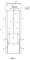
- Fig. 1 shows a vertical cross section of an elevator.
- the elevator comprises a car 10, an elevator shaft 20, a machine room 30, lifting machinery 40, ropes 41, and a counter weight 42.
- a frame called sling 11 surrounds the car 10.
- the lifting machinery 40 comprises a sheave 43, a machinery brake 46 and an electric motor 44 for rotating the sheave 43 via a shaft 45.
- the lifting machinery 40 moves the car 10 in a vertical direction Z upwards and downwards in the vertically extending elevator shaft 20.
- the sling 11 is connected by the ropes 41 via the sheave 43 to the counter weight 42.
- the sling 11 is further supported with gliding means 70 at guide rails 50 extending in the vertical direction in the shaft 20.
- the figure shows two guide rails 50 at opposite sides of the car 10.
- the gliding means 70 can comprise rolls rolling on the guide rails 50 or gliding shoes gliding on the guide rails 50 when the car 10 is moving upwards and downwards in the elevator shaft 20.
- the guide rails 50 are attached with fastening brackets 60 to the side wall structures 21 in the elevator shaft 20.
- the figure shows only two fastening brackets 60, but there are several fastening brackets 60 along the height of each guide rail 50.
- the gliding means 70 engaging with the guide rails 50 keep the car 10 in position in the horizontal plane when the car 10 moves upwards and downwards in the elevator shaft 20.
- the counter weight 42 is supported in a corresponding way on guide rails that are attached to the wall structure 21 of the shaft 20.
- the machinery brake 46 stops the rotation of the sheave 43 and thereby the movement of the elevator car 10.
- the car 10 transports people and/or goods between the landings in the building.
- the elevator shaft 20 can be formed so that the wall structure 21 is formed of solid walls or so that the wall structure 21 is formed of an open steel structure.
- Figure 2 shows a second vertical cross section of the lower region of an elevator shaft.
- the figure shows the pit 22 at the bottom of the shaft 20 below the lowermost landing L1.
- the depth Z1 of the pit 22 is more than 1.6 m, two stop buttons P1, P2 are required for maintenance operations to be performed from the pit 22.
- the first stop button P1 should be positioned in the shaft 20 above the floor of the lowermost landing L1 at a height Z2 of at least 1.0 m from the floor of the lowermost landing L1.
- the horizontal distance X1 from the front wall 21 of the shaft 20 to the first stop button P1 should be equal to or less than 0.75 m.
- the idea is that a mechanic should be able to operate the first stop button P1 when he is standing on the lowermost landing L1 and the landing door L1 is opened.
- the second stop button P2 should be positioned in the pit 22 at a height Z3 of less than 1.2 m above the floor of the pit 22.
- a maintenance drive unit 100 is positioned in the pit 22 e.g. at the bottom of the pit 22.
- the second stop button P2 may be positioned on the maintenance drive unit 100. Activation of the first stop button P1 or the second stop button P2 will open the safety circuit of the elevator preventing operation of the car 10 completely.
- the pit 22 can be accessed from the lowermost landing L1 when the car 10 is positioned above the landing door 25 of the lowermost landing L1.
- the mechanic may open the locking of the landing door 25 at the lowermost landing L1 with a triangle key, whereby the main control unit 200 of the elevator is set into a maintenance mode. Normal operation of the car 10 is prevented in the maintenance mode.
- the elevator car 10 can still be operated in maintenance mode e.g. from a maintenance access panel 300 positioned near a landing door at a landing. After unlocking the landing door 25 at the lowermost landing L1 with the triangle key, the mechanic opens the landing door 25 manually by force in order to be able to enter into the shaft 20 and to climb down to the pit 20 with a ladder.
- the mechanic closes the landing door 25 manually from the inside of the shaft 20 after entering into the shaft 20 in order to prevent third parties and objects from falling into the pit 22.
- the mechanic does not, however, lock the landing door 25 from the inside with the triangular key.
- the elevator should be kept in the maintenance mode all the time the mechanic is in the shaft 20.
- the maintenance access panel 300 is not necessarily positioned at the lowermost landing L1 and the landing door 25 is anyway closed when the mechanic is in the pit 22. There is thus a danger that a second mechanic may reset the elevator from the maintenance access panel 300.
- the second mechanic may change the operation mode from maintenance mode to normal operation mode or he may drive the car 10 within inspection drive in maintenance mode as he might not be aware of the first mechanic in the pit 22.
- the first mechanic in the pit 22 may thus be injured in case he is climbing up or down along the ladder in the pit 22 when the car 10 moves downwards.
- the buffers 23 at the bottom of the pit 22 will protect the first mechanic when he is at the bottom of the pit 22.
- first stop button P1 in the shaft 20 at the level of the landing door 25 at the lowermost landing L1.
- This first stop button P1 opens the safety circuit of the elevator and prevents normal operation as well as inspection drive in maintenance operation of the car 10.
- the mechanic When the mechanic has climbed down to the bottom of the pit 22 and wants to get access to the equipment to be maintained e.g. the safety gear positioned in connection with the bottom of the car 10, he uses the maintenance control unit 100 in the pit 22 in order to drive the car 10 in maintenance mode downwards to a suitable level. In order to be able to drive the car 10 from the maintenance control unit 100 at the bottom of the pit 22, the mechanic must deactivate the first stop button P1 so that the safety circuit is again closed. After he has deactivated the first stop button P1 the mechanic may drive the car 10 from the maintenance control unit 100.
- the car 10 may be driven from the maintenance access panel 300 by a second mechanic who is not aware of the first mechanic in the pit 22.
- stop buttons P1, P2 are required in a pit 22 having a depth of more than 1.6 m. It is quite normal in elevators of today that the depth of the pit 22 is more than 1.6 m, e.g. at a car velocity of 6 m/s, the depth of the pit 22 should be 4 m. Both stop buttons P1, P2 form part of the safety circuit of the elevator. This means that both stop buttons P1, P2 must be deactivated i.e. the contact must be closed in order to be able to operate the car 10.
- the first stop button P1 is positioned within the shaft 20 at the lowermost landing L1.
- the second stop button P2 is positioned in the pit 22 or in the maintenance control unit 100. The procedure when entering into the pit 22 is the following:
- Locking of the landing door 25 at the lowermost landing L1 with the triangular key will return the main control unit 200 of the elevator into normal operation mode.
- Both stop buttons P1, P2 must be deactivated in this arrangement in order to be able to drive the car 10 with the maintenance operation unit 100 from the pit 22.
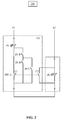
- FIG. 3 shows a principal connection implementing the invention.
- the circuit diagram shows the first stop button P1 positioned in the shaft 20 at the lowermost landing L1 and the second stop button P2 positioned in the maintenance control unit 100 in the pit 22.
- the first stop button P1 and the second stop button P2 are connected directly to the safety circuit S1, S2 of the elevator i.e. driving of the elevator car 10 is prevented completely when either of these stop buttons P1, P2 is activated i.e. the contact is open.
- the maintenance control unit 100 comprises further a drive switch SW1 provided with two contacts C1, C2.
- the first contact C1 of the drive switch SW1 is connected directly to the safety circuit S1, S2 and the second contact C2 of the drive switch SW1 is connected in parallel with the first stop button P1.
- the maintenance drive unit 100 comprises further a drive button P3, an upwards button P4 and a downwards button P5 connected in parallel with the first contact C1 of the drive switch S1.
- the drive button P3 is connected in series with the upwards button P4 and the downwards button P5.
- the upwards button P4 and the downwards button P5 are connected in parallel after the drive button P3.
- the drive button P3 has to be pressed in order to be able to drive the car 10. Pressing the drive button P3 and the upwards button P4 will drive the car 10 in maintenance mode upwards. Pressing the drive button P3 and the downwards button P5 will drive the car 10 in maintenance mode downwards.
- the second stop button P2 is only used as an emergency stop button in this arrangement.
- the second stop button P2 may be used as an emergency stop button e.g. in case the drive switch SW1 does not for some reason open the safety circuit S1, S2 when it should.
- the lower ends of the upwards button P4 and the downwards button P5 are naturally connected to their own control lines in order to be able to control the movement of the car 10 in the desired direction.
- the procedure when entering into the pit 22 in the arrangement according to the invention is the following:
- the second stop button P2 is in the embodiment of the invention shown in figure 3 integrated into the maintenance control unit 100, but this need not be the case.
- the second stop button P2 could be positioned outside the maintenance control unit 100 somewhere in the shaft 20 in accordance with the safety regulations. Such an embodiment would still be within the scope of the invention.
- the use of the invention is naturally not limited to the type of elevator disclosed in figure 1 , but the invention can be used in any type of elevator e.g. also in elevators lacking a machine room and/or a counterweight.
- the counterweight could be positioned on either side wall or on both side walls or on the back wall of the elevator shaft.
- the sheave, the machine brake and the motor could be positioned in the machine room or somewhere in the elevator shaft.
Landscapes
- Engineering & Computer Science (AREA)
- Automation & Control Theory (AREA)
- Civil Engineering (AREA)
- Mechanical Engineering (AREA)
- Structural Engineering (AREA)
- Maintenance And Inspection Apparatuses For Elevators (AREA)
- Elevator Control (AREA)
Abstract
Description
- The invention relates to a method and an arrangement for maintenance operation of an elevator.
- An elevator comprises typically a car, an elevator shaft, a machine room, lifting machinery, ropes, and a counter weight. The elevator car is positioned within a sling that supports the car. The lifting machinery comprises a sheave, a machinery brake and an electric motor for rotating the sheave. The lifting machinery moves the car in a vertical direction upwards and downwards in the vertically extending elevator shaft. The ropes connect the sling and thereby also the car via the sheave to the counter weight. The sling is further supported with gliding means on guide rails extending in the vertical direction in the shaft. The gliding means can comprise rolls rolling on the guide rails or gliding shoes gliding on the guide rails when the elevator car is mowing upwards and downwards in the elevator shaft. The guide rails are supported with fastening brackets on the side wall structures of the elevator shaft. The gliding means engaging with the guide rails keep the car in position in the horizontal plane when the car moves upwards and downwards in the elevator shaft. The counter weight is supported in a corresponding way on guide rails supported on the wall structure of the shaft. The elevator car transports people and/or goods between the landings in the building. The elevator shaft can be formed so that the wall structure is formed of solid walls or so that the wall structure is formed of an open steel structure.
- The elevator shaft is provided with a pit below the lowermost landing of the shaft. In a case the depth of the pit is more than 1.6 m, two stop buttons are required for maintenance operations to be performed from the pit. The first stop button should be positioned in the shaft above the floor of the lowermost landing so that a mechanic can operate the first stop button when he is standing on the lowermost landing and the landing door is opened. The second stop button should be positioned in the pit either separately or on a maintenance drive unit positioned in the pit. Operation of the car is prevented completely when the first or the second stop button is activated as they are part of the safety circuit of the elevator.
- The pit can be accessed from the lowermost landing when the car is positioned above the landing door of the first landing. The mechanic may open the lock of the landing door at a landing with a triangle key, whereby the operation mode of the elevator is changed into maintenance mode preventing normal operation of the elevator. The elevator can still be operated in maintenance mode e.g. from a maintenance access panel positioned near a landing door at a landing. Also opening of the hatch of the maintenance access panel with the triangle key will change the operation mode of the elevator into maintenance mode preventing normal operation of the elevator. After unlocking the landing door, the mechanic opens the landing door manually by force in order to be able to enter into the shaft and to climb down to the pit with a ladder. The mechanic closes the landing door manually from the shaft after entering into the shaft in order to prevent third parties and objects from falling into the pit.
- The elevator car must naturally be positioned above the landing door of the lowermost landing before the mechanic can enter into the shaft in order to climb down to the pit. The mechanic may drive the elevator car in maintenance mode from the maintenance access panel to a position above the landing door of the lowermost landing if this is needed.
- The procedure when entering into the pit is the following:
- 1. The mechanic opens the lock of the landing door at the lowermost landing with a triangular key, opens the landing door manually and activates the first stop button positioned within the shaft from the lowermost landing, enters into the shaft and closes the landing door manually from the inside of the shaft. Opening of the lock of the landing door sets the main control unit into maintenance mode preventing normal operation of the car. Activation of the first stop button opens the safety circuit of the elevator preventing operation of the car completely.
- 2. The mechanic climbs down along a ladder to the bottom of the pit and activates the second stop button positioned on the maintenance control unit and turns a drive switch on the maintenance control unit into a maintenance operation mode.
- 3. The mechanic climbs up along the ladder and deactivates the first stop button. The second stop button is still activated at this stage preventing operation of the car.
- 4. The mechanic climbs again down along the ladder and deactivates the second stop button. The mechanic can now drive the car with the maintenance control unit in maintenance mode downwards in the shaft to a position in which the mechanic can perform maintenance of the equipment positioned in connection with the bottom of the car.
- When the mechanic has performed the intended maintenance operation he must repeat the same procedure in a reverse order.
- 1. The mechanic drives the car with the maintenance control unit into a position above the landing door of the lowermost landing and activates the second stop button.
- 2. The mechanic climbs up along the ladder and activates the first stop button.
- 3. The mechanic climbs down along the ladder and turns the drive switch on the maintenance control unit into an inactive operation mode and deactivates the second stop button. The first stop button is still activated at this stage preventing operation of the car.
- 4. The mechanic climbs up along the ladder, opens the landing door on the lowermost landing, enters into the lowermost landing, deactivates the first stop button, and locks the landing door with the triangular key.
- Deactivation of the first stop button closes the safety circuit as the second stop button has been deactivated already earlier. Locking of the landing door at the lowermost landing with the triangular key will restore the elevator into normal operation mode.
- This procedure is rather cumbersome as the mechanic has to climb up and down from the pit along the ladder several times. There is also a tripping risk when the mechanic has to climb several times up and down along the ladder in the shaft. There is further the risk that the mechanic will be tempted to short cut the tedious procedure. The mechanic might by mistake or deliberately forget to activate the first stop button when he enters into the shaft and climbs down the ladder to the pit.
- This hazard has been prevented in prior art solutions so that the control logic of the elevator has been set to identify such a maintenance situation and to remember the situation. The control logic of the elevator identifies the start of the maintenance operation cycle when the mechanic opens the lock of the lowermost landing door with the triangle key. The control logic of the elevator remembers this maintenance operation cycle and prevents operation of the car until the maintenance operation cycle has been signed off by the mechanic at the maintenance access panel.
- The singular i.e. landing door is used throughout the application, but the landing door could naturally comprise one or several door panels. The landing door could be a swing type door or a gliding type door. The swing type door and the gliding type door could comprise one or several door panels.
- An object of the present invention is to achieve an improved method and arrangement for maintenance operation of an elevator.
- The method for maintenance operation of an elevator is characterized by what is stated in the characterizing portion of claim 1.
- The arrangement for maintenance operation of an elevator is characterized by what is stated in the characterizing portion of claim 3.
- The elevator comprises a car moving upwards and downwards between landings in a shaft being provided with a pit at a bottom of the shaft. The method comprises:
- unlocking and opening landing door at a lowermost landing manually, whereby normal operation of the car is prevented,
- activating a first stop button at the lowermost landing in the shaft, whereby a safety circuit of the elevator is opened so that operation of the car is prevented,
- entering into the shaft from the lowermost landing, closing the landing door, and climbing down to the bottom of the pit,
- turning a drive switch in a maintenance control unit positioned in the pit into a maintenance drive mode, whereby the first stop button is by-passed so that the car can be driven in maintenance mode from the maintenance control unit upwards and downwards in the shaft.
- The arrangement comprises:
- a first stop button being positioned at a lowermost landing in the shaft, said first stop button forming a part of a safety circuit of the elevator, whereby activation of said first stop button opens the safety circuit so that operation of the car is prevented,
- a maintenance control unit being positioned in the pit, said maintenance control unit comprising a drive switch having a maintenance drive mode in which the first stop button is by-passed so that the car can be driven in maintenance mode from the maintenance control unit upwards and downwards in the shaft.
- The invention makes the maintenance operation procedure in a shaft provided with a deep pit requiring two stop buttons much smoother compared to prior art solutions. There is no need for the mechanic to climb up and down the ladder several times at the beginning and at the end of the maintenance procedure. The mechanic has to climb down to the pit along the ladder only once at the beginning of the maintenance procedure and up from the pit along the ladder only once after completion of the maintenance procedure.
- The hazards related to the climbing upwards and downwards along the ladder are also reduced in the invention. The mechanic need to climb only once downwards and once upwards along the ladder in the inventive method and arrangement.
- The invention will in the following be described in greater detail by means of preferred embodiments with reference to the attached drawings, in which
-
Figure 1 shows a first vertical cross section of an elevator, -
Figure 2 shows a second vertical cross section of the lower region of an elevator shaft, -
Figure 3 shows a principal connection implementing the invention. -
Fig. 1 shows a vertical cross section of an elevator. The elevator comprises acar 10, anelevator shaft 20, amachine room 30, liftingmachinery 40,ropes 41, and acounter weight 42. A frame calledsling 11 surrounds thecar 10. Thelifting machinery 40 comprises asheave 43, amachinery brake 46 and anelectric motor 44 for rotating thesheave 43 via ashaft 45. Thelifting machinery 40 moves thecar 10 in a vertical direction Z upwards and downwards in the vertically extendingelevator shaft 20. Thesling 11 is connected by theropes 41 via thesheave 43 to thecounter weight 42. Thesling 11 is further supported with gliding means 70 atguide rails 50 extending in the vertical direction in theshaft 20. The figure shows twoguide rails 50 at opposite sides of thecar 10. The gliding means 70 can comprise rolls rolling on the guide rails 50 or gliding shoes gliding on the guide rails 50 when thecar 10 is moving upwards and downwards in theelevator shaft 20. The guide rails 50 are attached withfastening brackets 60 to theside wall structures 21 in theelevator shaft 20. The figure shows only twofastening brackets 60, but there areseveral fastening brackets 60 along the height of eachguide rail 50. The gliding means 70 engaging with the guide rails 50 keep thecar 10 in position in the horizontal plane when thecar 10 moves upwards and downwards in theelevator shaft 20. Thecounter weight 42 is supported in a corresponding way on guide rails that are attached to thewall structure 21 of theshaft 20. Themachinery brake 46 stops the rotation of thesheave 43 and thereby the movement of theelevator car 10. Thecar 10 transports people and/or goods between the landings in the building. Theelevator shaft 20 can be formed so that thewall structure 21 is formed of solid walls or so that thewall structure 21 is formed of an open steel structure. -
Figure 2 shows a second vertical cross section of the lower region of an elevator shaft. The figure shows thepit 22 at the bottom of theshaft 20 below the lowermost landing L1. There arebuffers 23 at the bottom of thepit 22 for softening the stop of thecar 10 if it tries to run at full speed to the bottom of theshaft 20. In a case the depth Z1 of thepit 22 is more than 1.6 m, two stop buttons P1, P2 are required for maintenance operations to be performed from thepit 22. The first stop button P1 should be positioned in theshaft 20 above the floor of the lowermost landing L1 at a height Z2 of at least 1.0 m from the floor of the lowermost landing L1. The horizontal distance X1 from thefront wall 21 of theshaft 20 to the first stop button P1 should be equal to or less than 0.75 m. The idea is that a mechanic should be able to operate the first stop button P1 when he is standing on the lowermost landing L1 and the landing door L1 is opened. The second stop button P2 should be positioned in thepit 22 at a height Z3 of less than 1.2 m above the floor of thepit 22. Amaintenance drive unit 100 is positioned in thepit 22 e.g. at the bottom of thepit 22. The second stop button P2 may be positioned on themaintenance drive unit 100. Activation of the first stop button P1 or the second stop button P2 will open the safety circuit of the elevator preventing operation of thecar 10 completely. - The
pit 22 can be accessed from the lowermost landing L1 when thecar 10 is positioned above the landingdoor 25 of the lowermost landing L1. The mechanic may open the locking of the landingdoor 25 at the lowermost landing L1 with a triangle key, whereby themain control unit 200 of the elevator is set into a maintenance mode. Normal operation of thecar 10 is prevented in the maintenance mode. Theelevator car 10 can still be operated in maintenance mode e.g. from amaintenance access panel 300 positioned near a landing door at a landing. After unlocking the landingdoor 25 at the lowermost landing L1 with the triangle key, the mechanic opens the landingdoor 25 manually by force in order to be able to enter into theshaft 20 and to climb down to thepit 20 with a ladder. The mechanic closes the landingdoor 25 manually from the inside of theshaft 20 after entering into theshaft 20 in order to prevent third parties and objects from falling into thepit 22. The mechanic does not, however, lock thelanding door 25 from the inside with the triangular key. The elevator should be kept in the maintenance mode all the time the mechanic is in theshaft 20. - The
maintenance access panel 300 is not necessarily positioned at the lowermost landing L1 and the landingdoor 25 is anyway closed when the mechanic is in thepit 22. There is thus a danger that a second mechanic may reset the elevator from themaintenance access panel 300. The second mechanic may change the operation mode from maintenance mode to normal operation mode or he may drive thecar 10 within inspection drive in maintenance mode as he might not be aware of the first mechanic in thepit 22. The first mechanic in thepit 22 may thus be injured in case he is climbing up or down along the ladder in thepit 22 when thecar 10 moves downwards. Thebuffers 23 at the bottom of thepit 22 will protect the first mechanic when he is at the bottom of thepit 22. In order to prevent this hazard there is a first stop button P1 in theshaft 20 at the level of the landingdoor 25 at the lowermost landing L1. This first stop button P1 opens the safety circuit of the elevator and prevents normal operation as well as inspection drive in maintenance operation of thecar 10. - When the mechanic has climbed down to the bottom of the
pit 22 and wants to get access to the equipment to be maintained e.g. the safety gear positioned in connection with the bottom of thecar 10, he uses themaintenance control unit 100 in thepit 22 in order to drive thecar 10 in maintenance mode downwards to a suitable level. In order to be able to drive thecar 10 from themaintenance control unit 100 at the bottom of thepit 22, the mechanic must deactivate the first stop button P1 so that the safety circuit is again closed. After he has deactivated the first stop button P1 the mechanic may drive thecar 10 from themaintenance control unit 100. In case thepit 22 is so deep that the mechanic does not reach the first push button P1 from the bottom of thepit 22, he must climb up along the ladder to the first push button P1 and then down again along the ladder to the bottom of thepit 22. The mechanic is exposed to the original hazard when he climbs down along the ladder after he has deactivated the first stop button P1 and when he climbs up from thepit 22 along the ladder after he has finished the maintenance work. Thecar 10 may be driven from themaintenance access panel 300 by a second mechanic who is not aware of the first mechanic in thepit 22. - In order to eliminate this hazard, two stop buttons P1, P2 are required in a
pit 22 having a depth of more than 1.6 m. It is quite normal in elevators of today that the depth of thepit 22 is more than 1.6 m, e.g. at a car velocity of 6 m/s, the depth of thepit 22 should be 4 m. Both stop buttons P1, P2 form part of the safety circuit of the elevator. This means that both stop buttons P1, P2 must be deactivated i.e. the contact must be closed in order to be able to operate thecar 10. The first stop button P1 is positioned within theshaft 20 at the lowermost landing L1. The second stop button P2 is positioned in thepit 22 or in themaintenance control unit 100. The procedure when entering into thepit 22 is the following: - 1. The mechanic unlocks the lock of the landing
door 25 at the lowermost landing L1 with a triangular key, opens the landingdoor 25 manually and activates the first stop button P1 positioned within theshaft 20 from the lowermost landing L1, enters into theshaft 20 and closes the landingdoor 25 from the inside of theshaft 20. Opening of the lock of the landingdoor 25 sets themain control unit 200 of the elevator into maintenance mode preventing normal operation of thecar 10. Activation of the first stop button P1 opens the safety circuit S1, S2 of the elevator preventing operation of thecar 10 completely. - 2. The mechanic climbs down along a ladder to the bottom of the
pit 22 and activates the second stop button P2 positioned on themaintenance control unit 100 and turns a drive switch on themaintenance control unit 100 into a maintenance operation mode. - 3. The mechanic climbs up along the ladder from the
pit 22 and deactivates the first stop button P1. The second stop button P2 is still activated at this stage preventing operation of thecar 10. - 4. The mechanic climbs again down to the bottom of the
pit 22 along the ladder and deactivates the second stop button P2. The mechanic can now drive thecar 10 with themaintenance control unit 100 in maintenance mode downwards in theshaft 20 to a position in which the mechanic can perform maintenance of the equipment positioned in connection with the bottom of thecar 10. - When the mechanic has finished the intended maintenance operation he must repeat the same procedure in a reverse order.
- 1. The mechanic drives the
car 10 with themaintenance control unit 100 into a position above the landingdoor 25 of the lowermost landing L1 and activates the second push button P2. Activation of the second push button P2 opens the safety circuit of the elevator preventing operation of thecar 10 completely. - 2. The mechanic climbs up along the ladder from the
pit 22 and activates the first stop button P1. - 3. The mechanic climbs down along the ladder to the bottom of the
pit 22 and turns the drive switch on themaintenance control unit 100 into an inactive operation mode and deactivates the second stop button P2. The first stop button P1 is still activated at this stage preventing operation of thecar 10. - 4. The mechanic climbs up along the ladder, opens the landing
door 25 on the lowermost landing L1, enters into the lowermost landing L1, deactivates the first stop button P2, closes the landingdoor 25 manually, and locks the landingdoor 25 with the triangular key. - Locking of the landing
door 25 at the lowermost landing L1 with the triangular key will return themain control unit 200 of the elevator into normal operation mode. - Both stop buttons P1, P2 must be deactivated in this arrangement in order to be able to drive the
car 10 with themaintenance operation unit 100 from thepit 22. - This procedure is rather cumbersome as the mechanic has to climb up and down from the pit along the ladder several times. There is also a tripping risk when the mechanic has to climb several times up and down along the ladder in the shaft. There is further the risk that the mechanic will be tempted to short cut the tedious procedure. The mechanic might by mistake or deliberately forget to activate the first stop button P1 when he enters into the
shaft 25 and climbs down the ladder to thepit 22. This hazard has been prevented in prior art solutions so that the control logic of the elevator has been set to identify such a maintenance situation and to remember the situation. The control logic of the elevator identifies the start of the maintenance operation cycle when the mechanic opens the locking of thelowermost landing door 25 with the triangle key. The control logic of the elevator remembers this maintenance operation cycle and prevents operation of thecar 10 until the maintenance operation cycle has been signed off by the mechanic at themaintenance access panel 300. -
Figure 3 shows a principal connection implementing the invention. The circuit diagram shows the first stop button P1 positioned in theshaft 20 at the lowermost landing L1 and the second stop button P2 positioned in themaintenance control unit 100 in thepit 22. The first stop button P1 and the second stop button P2 are connected directly to the safety circuit S1, S2 of the elevator i.e. driving of theelevator car 10 is prevented completely when either of these stop buttons P1, P2 is activated i.e. the contact is open. Themaintenance control unit 100 comprises further a drive switch SW1 provided with two contacts C1, C2. The first contact C1 of the drive switch SW1 is connected directly to the safety circuit S1, S2 and the second contact C2 of the drive switch SW1 is connected in parallel with the first stop button P1. When the drive switch SW1 is turned into maintenance drive mode, the first contact C1 is open and the second contact C2 is closed so that the first stop button P1 becomes by-passed. The first contact C1 opens the safety circuit S1, S2 so that it is not possible to drive thecar 10 from themaintenance control panel 300. The second contact C2 closes the safety circuit S1, S2 so that driving of thecar 10 is only possible from themaintenance control unit 100. Themaintenance drive unit 100 comprises further a drive button P3, an upwards button P4 and a downwards button P5 connected in parallel with the first contact C1 of the drive switch S1. The drive button P3 is connected in series with the upwards button P4 and the downwards button P5. The upwards button P4 and the downwards button P5 are connected in parallel after the drive button P3. The drive button P3 has to be pressed in order to be able to drive thecar 10. Pressing the drive button P3 and the upwards button P4 will drive thecar 10 in maintenance mode upwards. Pressing the drive button P3 and the downwards button P5 will drive thecar 10 in maintenance mode downwards. The second stop button P2 is only used as an emergency stop button in this arrangement. The second stop button P2 may be used as an emergency stop button e.g. in case the drive switch SW1 does not for some reason open the safety circuit S1, S2 when it should. The lower ends of the upwards button P4 and the downwards button P5 are naturally connected to their own control lines in order to be able to control the movement of thecar 10 in the desired direction. - The procedure when entering into the
pit 22 in the arrangement according to the invention is the following: - 1. The mechanic unlocks the landing
door 25 with the triangular key at the lowermost landing L1, changing the operational mode of the elevator into maintenance mode, and opens the landingdoor 25 manually. - 2. The mechanic activates the first stop button P1 from the landing L1, enters into the
shaft 20 and closes the landingdoor 25 from the inside of theshaft 20. Operation of thecar 10 is prevented completely as activation of the first stop button P1 opens the safety circuit S1, S2 of the elevator. - 3. The mechanic climbs down along the ladder to the bottom of the
pit 22 and turns the drive switch SW1 in themaintenance control unit 100 into maintenance drive mode. The first stop button P1 is thus by-passed i.e. the safety circuit S1, S2 is closed at the first stop button P1. The safety circuit S1, S2 is opened at the first contact C1 of the drive switch SW1 so that thecar 10 can be operated only from themaintenance control unit 100. - 4. The mechanic drives the
car 10 downwards with themaintenance control unit 100 into a suitable position so that he can perform the required maintenance work on the equipment positioned in connection with the bottom of thecar 10. - At the end of the maintenance operation the same procedure is repeated in the reverse order.
- 1. The mechanic drives the
car 10 into a position above thedoors 25 of the lowermost landing L1 and turns the drive switch SW1 into an inactive mode. The safety circuit S1, S2 is thus opened preventing operation of thecar 10 from outside thepit 22. - 2. The mechanic climbs up along the ladder to the lowermost landing L1, opens the landing
door 25, steps into the landing L1 and deactivates the first stop button P1, closes the landingdoor 25 and locks it with the triangular key, whereby the safety circuit S1, S2 is closed and the elevator returns to normal operation mode. - The second stop button P2 is in the embodiment of the invention shown in
figure 3 integrated into themaintenance control unit 100, but this need not be the case. The second stop button P2 could be positioned outside themaintenance control unit 100 somewhere in theshaft 20 in accordance with the safety regulations. Such an embodiment would still be within the scope of the invention. - The use of the invention is naturally not limited to the type of elevator disclosed in
figure 1 , but the invention can be used in any type of elevator e.g. also in elevators lacking a machine room and/or a counterweight. The counterweight could be positioned on either side wall or on both side walls or on the back wall of the elevator shaft. The sheave, the machine brake and the motor could be positioned in the machine room or somewhere in the elevator shaft. - It will be obvious to a person skilled in the art that, as the technology advances, the inventive concept can be implemented in various ways. The invention and its embodiments are not limited to the examples described above but may vary within the scope of the claims.
Claims (4)
- A method for maintenance operation of an elevator, the elevator comprising a car (10) moving upwards and downwards between landings (L1) in a shaft (20) being provided with a pit (22) at a bottom of the shaft (20), the method comprising:unlocking and opening landing door (25) at a lowermost landing (L1) manually, whereby normal operation of the car (10) is prevented,activating a first stop button (P1) at the lowermost landing (L1) in the shaft (20), whereby a safety circuit (S1, S2) of the elevator is opened so that operation of the car (10) is prevented,entering into the shaft (20) from the lowermost landing (L1), closing the landing door (25), and climbing down to the bottom of the pit (22),turning a drive switch (SW1) in a maintenance control unit (100) positioned in the pit (22) into a maintenance drive mode, whereby the first stop button (P1) is by-passed so that the car (10) can be driven in maintenance mode from the maintenance control unit (100) upwards and downwards in the shaft (20).
- The method according to claim 1, characterized in that the method further comprises:turning the drive switch (SW1) in the maintenance control unit (100) positioned in the pit (22) into an inactive mode, whereby the by-pass of the first stop button (P1) is deactivated so that the first stop button (P1), which is in the activated state, prevents operation of the car (10),climbing up from the pitch (22) to the lowermost landing (L1),opening the landing door (25) manually, passing through the landing door (25) opening to the lowermost landing (L1), deactivating the first stop button (P1), closing and locking the landing door (25) manually, whereby the elevator returns to normal operation mode.
- An arrangement for maintenance operation of an elevator, the elevator comprising a car (10) moving upwards and downwards between landings (L1) in a shaft (20) being provided with a pit (22) at a bottom of the shaft (20), the arrangement comprising:a first stop button (P1) being positioned at a lowermost landing (L1) in the shaft (20), said first stop button (P1) forming a part of a safety circuit (S1, S2) of the elevator, whereby activation of said first stop button (P1) opens the safety circuit (S1, S2) so that operation of the car (10) is prevented,a maintenance control unit (100) being positioned in the pit (22), said maintenance control unit (100) comprising a drive switch (SW1) having a maintenance drive mode in which the first stop button (P1) is by-passed so that the car (10) can be driven in maintenance mode from the maintenance control unit (100) upwards and downwards in the shaft (20).
- An arrangement according to claim 3, further comprising:a second stop button (P2) being positioned in the maintenance control unit (100) or in the shaft (20), said second stop button (P2) forming a part of a safety circuit (S1, S2) of the elevator, whereby activation of said second stop button (P2) opens the safety circuit (S1, S2) so that operation of the car (10) is prevented.
Priority Applications (3)
| Application Number | Priority Date | Filing Date | Title |
|---|---|---|---|
| EP15201824.8A EP3184477B1 (en) | 2015-12-22 | 2015-12-22 | A method and an arrangement for maintenance operation of an elevator |
| US15/387,383 US10549950B2 (en) | 2015-12-22 | 2016-12-21 | Method and an arrangement for enabling movement of the elevator while a maintanence technician is in the pit |
| CN201611198985.9A CN106904516B (en) | 2015-12-22 | 2016-12-22 | Method and apparatus for elevator maintenance operations |
Applications Claiming Priority (1)
| Application Number | Priority Date | Filing Date | Title |
|---|---|---|---|
| EP15201824.8A EP3184477B1 (en) | 2015-12-22 | 2015-12-22 | A method and an arrangement for maintenance operation of an elevator |
Publications (2)
| Publication Number | Publication Date |
|---|---|
| EP3184477A1 true EP3184477A1 (en) | 2017-06-28 |
| EP3184477B1 EP3184477B1 (en) | 2019-07-24 |
Family
ID=54883952
Family Applications (1)
| Application Number | Title | Priority Date | Filing Date |
|---|---|---|---|
| EP15201824.8A Active EP3184477B1 (en) | 2015-12-22 | 2015-12-22 | A method and an arrangement for maintenance operation of an elevator |
Country Status (3)
| Country | Link |
|---|---|
| US (1) | US10549950B2 (en) |
| EP (1) | EP3184477B1 (en) |
| CN (1) | CN106904516B (en) |
Cited By (1)
| Publication number | Priority date | Publication date | Assignee | Title |
|---|---|---|---|---|
| US11440773B2 (en) | 2018-03-16 | 2022-09-13 | Otis Elevator Company | Automatic rescue operation in an elevator system |
Families Citing this family (6)
| Publication number | Priority date | Publication date | Assignee | Title |
|---|---|---|---|---|
| JP6529665B2 (en) * | 2016-04-26 | 2019-06-12 | 三菱電機株式会社 | Elevator check operation device |
| EP3478615B1 (en) * | 2016-09-19 | 2022-06-29 | KONE Corporation | Method for setting an elevator into service mode |
| EP3336032B1 (en) * | 2016-12-14 | 2020-10-14 | Otis Elevator Company | Elevator safety system and method of operating an elevator system |
| EP3366628B1 (en) * | 2017-02-27 | 2019-06-19 | KONE Corporation | Safety system for a service space within an elevator shaft |
| CN113264427B (en) * | 2020-02-17 | 2022-10-14 | 上海三菱电梯有限公司 | Elevator landing calling device |
| CN111824905B (en) * | 2020-07-28 | 2021-08-20 | 康达电梯有限公司 | Intelligent elevator car overhauling device and overhauling method thereof |
Citations (3)
| Publication number | Priority date | Publication date | Assignee | Title |
|---|---|---|---|---|
| EP2072450A1 (en) * | 2007-12-21 | 2009-06-24 | Inventio Ag | Circuit for resetting an elevator safety chain |
| WO2013061355A1 (en) * | 2011-10-24 | 2013-05-02 | 株式会社 日立製作所 | Elevator with operation switching system |
| EP2623452A1 (en) * | 2010-10-01 | 2013-08-07 | Mitsubishi Electric Corporation | Elevator operation mode switching system |
Family Cites Families (16)
| Publication number | Priority date | Publication date | Assignee | Title |
|---|---|---|---|---|
| US5721403A (en) * | 1996-03-29 | 1998-02-24 | Otis Elevator Company | Selective circuit bypass for elevator system |
| DE10108772A1 (en) * | 2001-02-23 | 2002-11-21 | Otis Elevator Co | Elevator safety device |
| EP1719729B1 (en) * | 2004-02-26 | 2011-04-06 | Mitsubishi Denki Kabushiki Kaisha | Safety device of elevator |
| FI117010B (en) * | 2004-11-01 | 2006-05-15 | Kone Corp | Elevator remote control |
| JP2009511383A (en) * | 2005-10-05 | 2009-03-19 | オーチス エレベータ カンパニー | Elevator control in response to detection of hoistway entry |
| SG139660A1 (en) * | 2006-07-26 | 2008-02-29 | Inventio Ag | Method of controlling access to an elevator car |
| WO2008082380A1 (en) * | 2006-12-29 | 2008-07-10 | Otis Elevator Company | Warning system for mechanics in elevator hoistways |
| FI125141B (en) * | 2007-01-03 | 2015-06-15 | Kone Corp | Elevator safety device |
| FI121423B (en) * | 2009-04-23 | 2010-11-15 | Kone Corp | Safety arrangement for a lift |
| MX340867B (en) * | 2009-10-26 | 2016-07-28 | Inventio Ag * | Safety circuit in an elevator system. |
| WO2011076531A1 (en) * | 2009-12-21 | 2011-06-30 | Inventio Ag | Shaft access enabling device of an elevator system |
| RU2564433C2 (en) * | 2011-05-10 | 2015-09-27 | Отис Элевэйтор Компани | Monitoring remote control of hoisting system |
| JP5526092B2 (en) * | 2011-09-06 | 2014-06-18 | 株式会社日立製作所 | Electronic elevator |
| EP3012217B8 (en) * | 2014-10-21 | 2017-08-02 | KONE Corporation | Safety system for elevator |
| EP3159295B1 (en) * | 2015-10-22 | 2024-04-17 | Otis Elevator Company | Service alarm device for an elevator system |
| JP6529665B2 (en) * | 2016-04-26 | 2019-06-12 | 三菱電機株式会社 | Elevator check operation device |
-
2015
- 2015-12-22 EP EP15201824.8A patent/EP3184477B1/en active Active
-
2016
- 2016-12-21 US US15/387,383 patent/US10549950B2/en active Active
- 2016-12-22 CN CN201611198985.9A patent/CN106904516B/en active Active
Patent Citations (3)
| Publication number | Priority date | Publication date | Assignee | Title |
|---|---|---|---|---|
| EP2072450A1 (en) * | 2007-12-21 | 2009-06-24 | Inventio Ag | Circuit for resetting an elevator safety chain |
| EP2623452A1 (en) * | 2010-10-01 | 2013-08-07 | Mitsubishi Electric Corporation | Elevator operation mode switching system |
| WO2013061355A1 (en) * | 2011-10-24 | 2013-05-02 | 株式会社 日立製作所 | Elevator with operation switching system |
Cited By (1)
| Publication number | Priority date | Publication date | Assignee | Title |
|---|---|---|---|---|
| US11440773B2 (en) | 2018-03-16 | 2022-09-13 | Otis Elevator Company | Automatic rescue operation in an elevator system |
Also Published As
| Publication number | Publication date |
|---|---|
| CN106904516A (en) | 2017-06-30 |
| CN106904516B (en) | 2020-08-21 |
| EP3184477B1 (en) | 2019-07-24 |
| US20170174474A1 (en) | 2017-06-22 |
| US10549950B2 (en) | 2020-02-04 |
Similar Documents
| Publication | Publication Date | Title |
|---|---|---|
| US10549950B2 (en) | Method and an arrangement for enabling movement of the elevator while a maintanence technician is in the pit | |
| KR101558012B1 (en) | Circuit for resetting an elevator safety chain | |
| CN103964267B (en) | Method for providing access to a shaft in an elevator | |
| JP4742591B2 (en) | Elevator terminal safety device | |
| EP3336032B1 (en) | Elevator safety system and method of operating an elevator system | |
| EP3587323A1 (en) | Elevator system | |
| CN107592852B (en) | Hoistway lane control for elevator systems | |
| JPH0812228A (en) | Elevator device | |
| CN110626898B (en) | Elevator system | |
| CN211034778U (en) | Household elevator | |
| EP3659958B1 (en) | Column-integrated step for elevator systems | |
| US20190210836A1 (en) | Elevator maintenance access systems | |
| CN109534127A (en) | Elevator anti-fall device | |
| CN214527564U (en) | Limiting structure for midsplit variable frequency door machine | |
| JP7471894B2 (en) | Safety devices for construction elevators | |
| JP2013107759A (en) | Automatic elevator maintenance operation device | |
| JP5945020B1 (en) | Elevator equipment | |
| EP4304969A1 (en) | Access control arrangement, mobile device, conveyor system, and method for controlling access in conveyor system | |
| WO2020021155A1 (en) | Elevator arrangement | |
| JPH10231065A (en) | Safety device for elevator | |
| KR20120061327A (en) | Device for lifting the freight having safty means | |
| JPH06227780A (en) | Two-story elevator device | |
| JP2001316053A (en) | Operating device for rescuing passenger from elevator | |
| JPH06227778A (en) | Skew elevator | |
| JPH02132088A (en) | Elevator control device |
Legal Events
| Date | Code | Title | Description |
|---|---|---|---|
| PUAI | Public reference made under article 153(3) epc to a published international application that has entered the european phase |
Free format text: ORIGINAL CODE: 0009012 |
|
| STAA | Information on the status of an ep patent application or granted ep patent |
Free format text: STATUS: THE APPLICATION HAS BEEN PUBLISHED |
|
| AK | Designated contracting states |
Kind code of ref document: A1 Designated state(s): AL AT BE BG CH CY CZ DE DK EE ES FI FR GB GR HR HU IE IS IT LI LT LU LV MC MK MT NL NO PL PT RO RS SE SI SK SM TR |
|
| AX | Request for extension of the european patent |
Extension state: BA ME |
|
| STAA | Information on the status of an ep patent application or granted ep patent |
Free format text: STATUS: REQUEST FOR EXAMINATION WAS MADE |
|
| 17P | Request for examination filed |
Effective date: 20171218 |
|
| RBV | Designated contracting states (corrected) |
Designated state(s): AL AT BE BG CH CY CZ DE DK EE ES FI FR GB GR HR HU IE IS IT LI LT LU LV MC MK MT NL NO PL PT RO RS SE SI SK SM TR |
|
| GRAP | Despatch of communication of intention to grant a patent |
Free format text: ORIGINAL CODE: EPIDOSNIGR1 |
|
| STAA | Information on the status of an ep patent application or granted ep patent |
Free format text: STATUS: GRANT OF PATENT IS INTENDED |
|
| INTG | Intention to grant announced |
Effective date: 20190405 |
|
| GRAS | Grant fee paid |
Free format text: ORIGINAL CODE: EPIDOSNIGR3 |
|
| GRAA | (expected) grant |
Free format text: ORIGINAL CODE: 0009210 |
|
| STAA | Information on the status of an ep patent application or granted ep patent |
Free format text: STATUS: THE PATENT HAS BEEN GRANTED |
|
| AK | Designated contracting states |
Kind code of ref document: B1 Designated state(s): AL AT BE BG CH CY CZ DE DK EE ES FI FR GB GR HR HU IE IS IT LI LT LU LV MC MK MT NL NO PL PT RO RS SE SI SK SM TR |
|
| REG | Reference to a national code |
Ref country code: GB Ref legal event code: FG4D |
|
| REG | Reference to a national code |
Ref country code: CH Ref legal event code: EP |
|
| REG | Reference to a national code |
Ref country code: DE Ref legal event code: R096 Ref document number: 602015034212 Country of ref document: DE |
|
| REG | Reference to a national code |
Ref country code: AT Ref legal event code: REF Ref document number: 1157933 Country of ref document: AT Kind code of ref document: T Effective date: 20190815 |
|
| REG | Reference to a national code |
Ref country code: IE Ref legal event code: FG4D |
|
| REG | Reference to a national code |
Ref country code: NL Ref legal event code: MP Effective date: 20190724 |
|
| REG | Reference to a national code |
Ref country code: LT Ref legal event code: MG4D |
|
| REG | Reference to a national code |
Ref country code: AT Ref legal event code: MK05 Ref document number: 1157933 Country of ref document: AT Kind code of ref document: T Effective date: 20190724 |
|
| PG25 | Lapsed in a contracting state [announced via postgrant information from national office to epo] |
Ref country code: SE Free format text: LAPSE BECAUSE OF FAILURE TO SUBMIT A TRANSLATION OF THE DESCRIPTION OR TO PAY THE FEE WITHIN THE PRESCRIBED TIME-LIMIT Effective date: 20190724 Ref country code: BG Free format text: LAPSE BECAUSE OF FAILURE TO SUBMIT A TRANSLATION OF THE DESCRIPTION OR TO PAY THE FEE WITHIN THE PRESCRIBED TIME-LIMIT Effective date: 20191024 Ref country code: AT Free format text: LAPSE BECAUSE OF FAILURE TO SUBMIT A TRANSLATION OF THE DESCRIPTION OR TO PAY THE FEE WITHIN THE PRESCRIBED TIME-LIMIT Effective date: 20190724 Ref country code: HR Free format text: LAPSE BECAUSE OF FAILURE TO SUBMIT A TRANSLATION OF THE DESCRIPTION OR TO PAY THE FEE WITHIN THE PRESCRIBED TIME-LIMIT Effective date: 20190724 Ref country code: NO Free format text: LAPSE BECAUSE OF FAILURE TO SUBMIT A TRANSLATION OF THE DESCRIPTION OR TO PAY THE FEE WITHIN THE PRESCRIBED TIME-LIMIT Effective date: 20191024 Ref country code: LT Free format text: LAPSE BECAUSE OF FAILURE TO SUBMIT A TRANSLATION OF THE DESCRIPTION OR TO PAY THE FEE WITHIN THE PRESCRIBED TIME-LIMIT Effective date: 20190724 Ref country code: NL Free format text: LAPSE BECAUSE OF FAILURE TO SUBMIT A TRANSLATION OF THE DESCRIPTION OR TO PAY THE FEE WITHIN THE PRESCRIBED TIME-LIMIT Effective date: 20190724 Ref country code: PT Free format text: LAPSE BECAUSE OF FAILURE TO SUBMIT A TRANSLATION OF THE DESCRIPTION OR TO PAY THE FEE WITHIN THE PRESCRIBED TIME-LIMIT Effective date: 20191125 Ref country code: FI Free format text: LAPSE BECAUSE OF FAILURE TO SUBMIT A TRANSLATION OF THE DESCRIPTION OR TO PAY THE FEE WITHIN THE PRESCRIBED TIME-LIMIT Effective date: 20190724 |
|
| PG25 | Lapsed in a contracting state [announced via postgrant information from national office to epo] |
Ref country code: LV Free format text: LAPSE BECAUSE OF FAILURE TO SUBMIT A TRANSLATION OF THE DESCRIPTION OR TO PAY THE FEE WITHIN THE PRESCRIBED TIME-LIMIT Effective date: 20190724 Ref country code: GR Free format text: LAPSE BECAUSE OF FAILURE TO SUBMIT A TRANSLATION OF THE DESCRIPTION OR TO PAY THE FEE WITHIN THE PRESCRIBED TIME-LIMIT Effective date: 20191025 Ref country code: ES Free format text: LAPSE BECAUSE OF FAILURE TO SUBMIT A TRANSLATION OF THE DESCRIPTION OR TO PAY THE FEE WITHIN THE PRESCRIBED TIME-LIMIT Effective date: 20190724 Ref country code: RS Free format text: LAPSE BECAUSE OF FAILURE TO SUBMIT A TRANSLATION OF THE DESCRIPTION OR TO PAY THE FEE WITHIN THE PRESCRIBED TIME-LIMIT Effective date: 20190724 Ref country code: IS Free format text: LAPSE BECAUSE OF FAILURE TO SUBMIT A TRANSLATION OF THE DESCRIPTION OR TO PAY THE FEE WITHIN THE PRESCRIBED TIME-LIMIT Effective date: 20191124 Ref country code: AL Free format text: LAPSE BECAUSE OF FAILURE TO SUBMIT A TRANSLATION OF THE DESCRIPTION OR TO PAY THE FEE WITHIN THE PRESCRIBED TIME-LIMIT Effective date: 20190724 |
|
| PG25 | Lapsed in a contracting state [announced via postgrant information from national office to epo] |
Ref country code: TR Free format text: LAPSE BECAUSE OF FAILURE TO SUBMIT A TRANSLATION OF THE DESCRIPTION OR TO PAY THE FEE WITHIN THE PRESCRIBED TIME-LIMIT Effective date: 20190724 |
|
| PG25 | Lapsed in a contracting state [announced via postgrant information from national office to epo] |
Ref country code: EE Free format text: LAPSE BECAUSE OF FAILURE TO SUBMIT A TRANSLATION OF THE DESCRIPTION OR TO PAY THE FEE WITHIN THE PRESCRIBED TIME-LIMIT Effective date: 20190724 Ref country code: IT Free format text: LAPSE BECAUSE OF FAILURE TO SUBMIT A TRANSLATION OF THE DESCRIPTION OR TO PAY THE FEE WITHIN THE PRESCRIBED TIME-LIMIT Effective date: 20190724 Ref country code: DK Free format text: LAPSE BECAUSE OF FAILURE TO SUBMIT A TRANSLATION OF THE DESCRIPTION OR TO PAY THE FEE WITHIN THE PRESCRIBED TIME-LIMIT Effective date: 20190724 Ref country code: RO Free format text: LAPSE BECAUSE OF FAILURE TO SUBMIT A TRANSLATION OF THE DESCRIPTION OR TO PAY THE FEE WITHIN THE PRESCRIBED TIME-LIMIT Effective date: 20190724 Ref country code: PL Free format text: LAPSE BECAUSE OF FAILURE TO SUBMIT A TRANSLATION OF THE DESCRIPTION OR TO PAY THE FEE WITHIN THE PRESCRIBED TIME-LIMIT Effective date: 20190724 |
|
| PG25 | Lapsed in a contracting state [announced via postgrant information from national office to epo] |
Ref country code: IS Free format text: LAPSE BECAUSE OF FAILURE TO SUBMIT A TRANSLATION OF THE DESCRIPTION OR TO PAY THE FEE WITHIN THE PRESCRIBED TIME-LIMIT Effective date: 20200224 Ref country code: SK Free format text: LAPSE BECAUSE OF FAILURE TO SUBMIT A TRANSLATION OF THE DESCRIPTION OR TO PAY THE FEE WITHIN THE PRESCRIBED TIME-LIMIT Effective date: 20190724 Ref country code: CZ Free format text: LAPSE BECAUSE OF FAILURE TO SUBMIT A TRANSLATION OF THE DESCRIPTION OR TO PAY THE FEE WITHIN THE PRESCRIBED TIME-LIMIT Effective date: 20190724 Ref country code: SM Free format text: LAPSE BECAUSE OF FAILURE TO SUBMIT A TRANSLATION OF THE DESCRIPTION OR TO PAY THE FEE WITHIN THE PRESCRIBED TIME-LIMIT Effective date: 20190724 |
|
| REG | Reference to a national code |
Ref country code: DE Ref legal event code: R097 Ref document number: 602015034212 Country of ref document: DE |
|
| PLBE | No opposition filed within time limit |
Free format text: ORIGINAL CODE: 0009261 |
|
| STAA | Information on the status of an ep patent application or granted ep patent |
Free format text: STATUS: NO OPPOSITION FILED WITHIN TIME LIMIT |
|
| PG2D | Information on lapse in contracting state deleted |
Ref country code: IS |
|
| REG | Reference to a national code |
Ref country code: CH Ref legal event code: PL |
|
| 26N | No opposition filed |
Effective date: 20200603 |
|
| REG | Reference to a national code |
Ref country code: BE Ref legal event code: MM Effective date: 20191231 |
|
| PG25 | Lapsed in a contracting state [announced via postgrant information from national office to epo] |
Ref country code: SI Free format text: LAPSE BECAUSE OF FAILURE TO SUBMIT A TRANSLATION OF THE DESCRIPTION OR TO PAY THE FEE WITHIN THE PRESCRIBED TIME-LIMIT Effective date: 20190724 Ref country code: MC Free format text: LAPSE BECAUSE OF FAILURE TO SUBMIT A TRANSLATION OF THE DESCRIPTION OR TO PAY THE FEE WITHIN THE PRESCRIBED TIME-LIMIT Effective date: 20190724 |
|
| PG25 | Lapsed in a contracting state [announced via postgrant information from national office to epo] |
Ref country code: LU Free format text: LAPSE BECAUSE OF NON-PAYMENT OF DUE FEES Effective date: 20191222 Ref country code: IE Free format text: LAPSE BECAUSE OF NON-PAYMENT OF DUE FEES Effective date: 20191222 |
|
| PG25 | Lapsed in a contracting state [announced via postgrant information from national office to epo] |
Ref country code: BE Free format text: LAPSE BECAUSE OF NON-PAYMENT OF DUE FEES Effective date: 20191231 Ref country code: CH Free format text: LAPSE BECAUSE OF NON-PAYMENT OF DUE FEES Effective date: 20191231 Ref country code: LI Free format text: LAPSE BECAUSE OF NON-PAYMENT OF DUE FEES Effective date: 20191231 |
|
| PG25 | Lapsed in a contracting state [announced via postgrant information from national office to epo] |
Ref country code: CY Free format text: LAPSE BECAUSE OF FAILURE TO SUBMIT A TRANSLATION OF THE DESCRIPTION OR TO PAY THE FEE WITHIN THE PRESCRIBED TIME-LIMIT Effective date: 20190724 |
|
| PG25 | Lapsed in a contracting state [announced via postgrant information from national office to epo] |
Ref country code: MT Free format text: LAPSE BECAUSE OF FAILURE TO SUBMIT A TRANSLATION OF THE DESCRIPTION OR TO PAY THE FEE WITHIN THE PRESCRIBED TIME-LIMIT Effective date: 20190724 Ref country code: HU Free format text: LAPSE BECAUSE OF FAILURE TO SUBMIT A TRANSLATION OF THE DESCRIPTION OR TO PAY THE FEE WITHIN THE PRESCRIBED TIME-LIMIT; INVALID AB INITIO Effective date: 20151222 |
|
| PG25 | Lapsed in a contracting state [announced via postgrant information from national office to epo] |
Ref country code: MK Free format text: LAPSE BECAUSE OF FAILURE TO SUBMIT A TRANSLATION OF THE DESCRIPTION OR TO PAY THE FEE WITHIN THE PRESCRIBED TIME-LIMIT Effective date: 20190724 |
|
| P01 | Opt-out of the competence of the unified patent court (upc) registered |
Effective date: 20230525 |
|
| PGFP | Annual fee paid to national office [announced via postgrant information from national office to epo] |
Ref country code: GB Payment date: 20231220 Year of fee payment: 9 |
|
| PGFP | Annual fee paid to national office [announced via postgrant information from national office to epo] |
Ref country code: FR Payment date: 20231221 Year of fee payment: 9 Ref country code: DE Payment date: 20231214 Year of fee payment: 9 |