EP3184396A1 - Backrest, vehicle, and guide track transportation system - Google Patents
Backrest, vehicle, and guide track transportation system Download PDFInfo
- Publication number
- EP3184396A1 EP3184396A1 EP15847399.1A EP15847399A EP3184396A1 EP 3184396 A1 EP3184396 A1 EP 3184396A1 EP 15847399 A EP15847399 A EP 15847399A EP 3184396 A1 EP3184396 A1 EP 3184396A1
- Authority
- EP
- European Patent Office
- Prior art keywords
- wall surface
- vehicle
- backrest
- retaining member
- passenger
- Prior art date
- Legal status (The legal status is an assumption and is not a legal conclusion. Google has not performed a legal analysis and makes no representation as to the accuracy of the status listed.)
- Withdrawn
Links
- 239000000463 material Substances 0.000 claims description 28
- 238000005192 partition Methods 0.000 claims description 26
- 238000000638 solvent extraction Methods 0.000 claims description 9
- 239000000835 fiber Substances 0.000 claims description 7
- 230000000717 retained effect Effects 0.000 abstract 1
- 238000010586 diagram Methods 0.000 description 19
- 239000004744 fabric Substances 0.000 description 6
- 239000011347 resin Substances 0.000 description 6
- 229920005989 resin Polymers 0.000 description 6
- 210000002414 leg Anatomy 0.000 description 4
- 238000003860 storage Methods 0.000 description 4
- 230000032258 transport Effects 0.000 description 4
- JOYRKODLDBILNP-UHFFFAOYSA-N Ethyl urethane Chemical compound CCOC(N)=O JOYRKODLDBILNP-UHFFFAOYSA-N 0.000 description 3
- 210000001217 buttock Anatomy 0.000 description 3
- 239000011162 core material Substances 0.000 description 3
- 239000013013 elastic material Substances 0.000 description 3
- 210000004177 elastic tissue Anatomy 0.000 description 3
- 239000006260 foam Substances 0.000 description 3
- 230000002093 peripheral effect Effects 0.000 description 3
- 229920003023 plastic Polymers 0.000 description 3
- 239000004033 plastic Substances 0.000 description 3
- 238000009751 slip forming Methods 0.000 description 3
- 238000004804 winding Methods 0.000 description 3
- 238000005452 bending Methods 0.000 description 2
- 230000037237 body shape Effects 0.000 description 2
- 239000011248 coating agent Substances 0.000 description 2
- 238000000576 coating method Methods 0.000 description 2
- 238000004519 manufacturing process Methods 0.000 description 2
- 238000000034 method Methods 0.000 description 2
- 238000009941 weaving Methods 0.000 description 2
- 206010040007 Sense of oppression Diseases 0.000 description 1
- 238000013459 approach Methods 0.000 description 1
- 230000008859 change Effects 0.000 description 1
- 238000005520 cutting process Methods 0.000 description 1
- 238000013461 design Methods 0.000 description 1
- 230000000694 effects Effects 0.000 description 1
- 230000002708 enhancing effect Effects 0.000 description 1
- 238000009501 film coating Methods 0.000 description 1
- 230000006872 improvement Effects 0.000 description 1
- 238000009434 installation Methods 0.000 description 1
- 239000010985 leather Substances 0.000 description 1
- 239000002184 metal Substances 0.000 description 1
- 238000012986 modification Methods 0.000 description 1
- 230000004048 modification Effects 0.000 description 1
- 239000005445 natural material Substances 0.000 description 1
- 230000035699 permeability Effects 0.000 description 1
- 229920000728 polyester Polymers 0.000 description 1
- 238000012545 processing Methods 0.000 description 1
- 238000000926 separation method Methods 0.000 description 1
- 239000007787 solid Substances 0.000 description 1
- 239000010409 thin film Substances 0.000 description 1
- 125000000391 vinyl group Chemical group [H]C([*])=C([H])[H] 0.000 description 1
- 229920002554 vinyl polymer Polymers 0.000 description 1
- 210000000707 wrist Anatomy 0.000 description 1
Images







Classifications
-
- B—PERFORMING OPERATIONS; TRANSPORTING
- B61—RAILWAYS
- B61D—BODY DETAILS OR KINDS OF RAILWAY VEHICLES
- B61D33/00—Seats
- B61D33/0007—Details; Accessories
-
- B—PERFORMING OPERATIONS; TRANSPORTING
- B61—RAILWAYS
- B61D—BODY DETAILS OR KINDS OF RAILWAY VEHICLES
- B61D37/00—Other furniture or furnishings
-
- B—PERFORMING OPERATIONS; TRANSPORTING
- B60—VEHICLES IN GENERAL
- B60R—VEHICLES, VEHICLE FITTINGS, OR VEHICLE PARTS, NOT OTHERWISE PROVIDED FOR
- B60R21/00—Arrangements or fittings on vehicles for protecting or preventing injuries to occupants or pedestrians in case of accidents or other traffic risks
- B60R21/02—Occupant safety arrangements or fittings, e.g. crash pads
- B60R21/04—Padded linings for the vehicle interior ; Energy absorbing structures associated with padded or non-padded linings
-
- A—HUMAN NECESSITIES
- A47—FURNITURE; DOMESTIC ARTICLES OR APPLIANCES; COFFEE MILLS; SPICE MILLS; SUCTION CLEANERS IN GENERAL
- A47C—CHAIRS; SOFAS; BEDS
- A47C16/00—Stand-alone rests or supports for feet, legs, arms, back or head
-
- A—HUMAN NECESSITIES
- A47—FURNITURE; DOMESTIC ARTICLES OR APPLIANCES; COFFEE MILLS; SPICE MILLS; SUCTION CLEANERS IN GENERAL
- A47C—CHAIRS; SOFAS; BEDS
- A47C16/00—Stand-alone rests or supports for feet, legs, arms, back or head
- A47C16/005—Back-rests
-
- A—HUMAN NECESSITIES
- A62—LIFE-SAVING; FIRE-FIGHTING
- A62B—DEVICES, APPARATUS OR METHODS FOR LIFE-SAVING
- A62B35/00—Safety belts or body harnesses; Similar equipment for limiting displacement of the human body, especially in case of sudden changes of motion
- A62B35/0006—Harnesses; Accessories therefor
-
- B—PERFORMING OPERATIONS; TRANSPORTING
- B60—VEHICLES IN GENERAL
- B60N—SEATS SPECIALLY ADAPTED FOR VEHICLES; VEHICLE PASSENGER ACCOMMODATION NOT OTHERWISE PROVIDED FOR
- B60N2/00—Seats specially adapted for vehicles; Arrangement or mounting of seats in vehicles
- B60N2/64—Back-rests or cushions
-
- B—PERFORMING OPERATIONS; TRANSPORTING
- B60—VEHICLES IN GENERAL
- B60N—SEATS SPECIALLY ADAPTED FOR VEHICLES; VEHICLE PASSENGER ACCOMMODATION NOT OTHERWISE PROVIDED FOR
- B60N2/00—Seats specially adapted for vehicles; Arrangement or mounting of seats in vehicles
- B60N2/64—Back-rests or cushions
- B60N2/643—Back-rests or cushions shape of the back-rests
-
- B—PERFORMING OPERATIONS; TRANSPORTING
- B60—VEHICLES IN GENERAL
- B60N—SEATS SPECIALLY ADAPTED FOR VEHICLES; VEHICLE PASSENGER ACCOMMODATION NOT OTHERWISE PROVIDED FOR
- B60N2/00—Seats specially adapted for vehicles; Arrangement or mounting of seats in vehicles
- B60N2/64—Back-rests or cushions
- B60N2/646—Back-rests or cushions shape of the cushion
-
- B—PERFORMING OPERATIONS; TRANSPORTING
- B61—RAILWAYS
- B61D—BODY DETAILS OR KINDS OF RAILWAY VEHICLES
- B61D1/00—Carriages for ordinary railway passenger traffic
- B61D1/04—General arrangements of seats
-
- B—PERFORMING OPERATIONS; TRANSPORTING
- B61—RAILWAYS
- B61D—BODY DETAILS OR KINDS OF RAILWAY VEHICLES
- B61D33/00—Seats
- B61D33/0057—Seats characterised by their mounting in vehicles
- B61D33/0064—Seats characterised by their mounting in vehicles not adjustably mounted; supports therefor
-
- B—PERFORMING OPERATIONS; TRANSPORTING
- B60—VEHICLES IN GENERAL
- B60N—SEATS SPECIALLY ADAPTED FOR VEHICLES; VEHICLE PASSENGER ACCOMMODATION NOT OTHERWISE PROVIDED FOR
- B60N2/00—Seats specially adapted for vehicles; Arrangement or mounting of seats in vehicles
- B60N2/24—Seats specially adapted for vehicles; Arrangement or mounting of seats in vehicles for particular purposes or particular vehicles
- B60N2002/247—Seats specially adapted for vehicles; Arrangement or mounting of seats in vehicles for particular purposes or particular vehicles to support passengers in a half-standing position
-
- B—PERFORMING OPERATIONS; TRANSPORTING
- B60—VEHICLES IN GENERAL
- B60R—VEHICLES, VEHICLE FITTINGS, OR VEHICLE PARTS, NOT OTHERWISE PROVIDED FOR
- B60R21/00—Arrangements or fittings on vehicles for protecting or preventing injuries to occupants or pedestrians in case of accidents or other traffic risks
- B60R21/02—Occupant safety arrangements or fittings, e.g. crash pads
- B60R2021/0206—Self-supporting restraint systems, e.g. restraining arms, plates or the like
-
- B—PERFORMING OPERATIONS; TRANSPORTING
- B60—VEHICLES IN GENERAL
- B60R—VEHICLES, VEHICLE FITTINGS, OR VEHICLE PARTS, NOT OTHERWISE PROVIDED FOR
- B60R21/00—Arrangements or fittings on vehicles for protecting or preventing injuries to occupants or pedestrians in case of accidents or other traffic risks
- B60R21/02—Occupant safety arrangements or fittings, e.g. crash pads
- B60R2021/0206—Self-supporting restraint systems, e.g. restraining arms, plates or the like
- B60R2021/0246—Self-supporting restraint systems, e.g. restraining arms, plates or the like mounted on side walls
-
- B—PERFORMING OPERATIONS; TRANSPORTING
- B60—VEHICLES IN GENERAL
- B60R—VEHICLES, VEHICLE FITTINGS, OR VEHICLE PARTS, NOT OTHERWISE PROVIDED FOR
- B60R21/00—Arrangements or fittings on vehicles for protecting or preventing injuries to occupants or pedestrians in case of accidents or other traffic risks
- B60R21/02—Occupant safety arrangements or fittings, e.g. crash pads
-
- B—PERFORMING OPERATIONS; TRANSPORTING
- B60—VEHICLES IN GENERAL
- B60Y—INDEXING SCHEME RELATING TO ASPECTS CROSS-CUTTING VEHICLE TECHNOLOGY
- B60Y2200/00—Type of vehicle
- B60Y2200/30—Railway vehicles
-
- B—PERFORMING OPERATIONS; TRANSPORTING
- B61—RAILWAYS
- B61D—BODY DETAILS OR KINDS OF RAILWAY VEHICLES
- B61D33/00—Seats
-
- B—PERFORMING OPERATIONS; TRANSPORTING
- B64—AIRCRAFT; AVIATION; COSMONAUTICS
- B64D—EQUIPMENT FOR FITTING IN OR TO AIRCRAFT; FLIGHT SUITS; PARACHUTES; ARRANGEMENT OR MOUNTING OF POWER PLANTS OR PROPULSION TRANSMISSIONS IN AIRCRAFT
- B64D11/00—Passenger or crew accommodation; Flight-deck installations not otherwise provided for
- B64D11/06—Arrangements of seats, or adaptations or details specially adapted for aircraft seats
Definitions
- a configuration in which seats are provided to transport passengers in a sitting posture is employed.
- this configuration it is possible to provide seats with respect to a predetermined number of passengers.
- passengers who do not sit on seats and are in a standing posture on crowded occasions Since the vehicle shakes or vibrates, passengers in the standing posture generally try to secure a stable posture by grasping on a structure inside the vehicle, such as a strap or a handrail, or by leaning on a wall surface or the like at hand.
- the base member 10 is formed so that it is bent to be convex from the inner wall surface W in a direction from an upper side to a lower side along the direction of the reference line 13, in a cross-sectional view intersecting the reference line 13. Both edges of the base member 10 in a vertical direction are formed in a shape corresponding to the inner wall surface W of the vehicle body 101 to form an attachment portion 38. In a state where the attachment portion 38 is in contact with the inner wall surface W, the base member 10 is attached to the inner wall surface W.
- the backrest 8 for the flat part formed as described above a passenger leans back while retaining the passenger's back thereon (see FIG. 5B ).
- the retaining member 11 is formed of an elastic material, it is possible to give excellent ride comfort to a passenger, compared with a case where the passenger directly leans on a hard wall surface.
- the front surface 14B of the retaining member 11 has a curved shape along the front surface 14A of the base member 10.
- the front surface 14B of the retaining member 11 is formed in a concave shape in which the entirety thereof is smoothly recessed toward the main surface when seen in the extending direction of the reference line 13, and is formed in a shape that protrudes while being bent toward a direction away from the main surface 12 when seen in the direction intersecting the reference line 13.
- the retaining member 11 when seen in the extending direction of the reference line 13, includes a first curved surface 21 provided along the front surface 14A on the side of the first base member 23, and a second curved surface 22 provided along the front surface 14A on the side of the second base member 24.
- Both of the first curved surface 21 and the second curved surface 22 are curved surfaces formed to be bent toward the attachment portion 38 (main surface 12) in the extending direction of the reference line 13.
- the first curved surface 21 and the second curved surface 22 are continuously formed to form a single curved surface.
- the front surface 14 of the retaining member 11 exhibits a concave shape in which the entirety thereof is smooth toward the main surface 12.
- a sectional view of the backrest 9 for the corner part including the retaining member seen in the direction intersecting the reference line 13 is approximately the same as the sectional view of the backrest 8 for the flat part shown in FIG. 5A , but the invention is not limited thereto.
- the thickness of the retaining member 11 may be formed to be greater than the thickness of the base member 10, such as the backrest 8 for the flat part shown in FIG. 6A
- the front surface 14B of the retaining member 11 may be formed to have a curved shape such as a convex shape from the front surface 14A of the base member 10.
- the backrest 9 for the corner part formed as described above is disposed at a position of such a height that an upper edge 8A of the inner wall surface W is approximately disposed at the height of the passenger's shoulders and a lower edge 8B is approximately disposed at the height of the passenger's legs, for example.
- the retaining member 11 is formed of an elastic material, it is possible to provide excellent ride comfort to a passenger, compared with a case where the passenger directly leans on a hard wall surface.
- a concave portion 17 that is recessed in a direction approaching the main surface 12 from the front surface 14B is formed in the retaining member 11 when seen in the direction intersecting the reference line 13.
- at least one convex portion 18 that is provided along the extending direction of the reference line 13 in parallel to the concave portion 17 and protrudes in a direction away from the base member 10 (main surface 12) is formed on the front surface 14B of the retaining member 11.
- two convex portions 18 and 18 are provided. Positions and dimensions of the concave portion 17 and the convex portions 18 may be suitably designed to approximately follow up a curve from the waist to the buttocks of the passenger's body.
- a first convex portion 19 formed to follow up the waist and a second convex portion 20 formed to follow up the buttocks are formed in the order from an upper side to a lower side of the retaining member 11.
- the front surface 14B of the retaining member 11 is formed in a concave shape by the first curved surface 21 and the second curved surface 22 when seen in the extending direction of the reference line 13.
- the front surface 14B of the retaining member 11 is formed in a concave shape by the first curved surface 21 and the second curved surface 22 when seen in the extending direction of the reference line 13.
- the retaining member 11 is formed of an elastic restoring force
- a configuration in which a curved shaped core material having the first curved surface 21, the second curved surface 22, and the concave portion 17 and the convex portions 18 as described above is provided in the retaining member 11 may be employed.
- the core material for example, a plate-shaped resin material that has a curved shape and is integrally molded, or the like, may be considered. According to such a configuration, as a passenger leans back, the retaining member 11 is elastically deformed along the curved shape of the core material. Thus, it is possible to enhance aesthetics, and to obtain excellent habitability for passengers.
- the rod-shaped member 34 may be formed by bending a circular tube member or the like made of metal, for example, into an arc shape. In the state of being installed on the inner wall surface W, the plurality of rod-shaped members 34 are approximately parallel to each other. Further, the size of separation between the rod-shaped members 34 is set to be sufficiently larger than the width of the passenger's body.
- the respective end portions of the rod-shaped members 34 are respectively fixed to four fixation positions 35 on the inner wall surface W using fixing members (not shown). A rectangular area formed by connecting the four fixation positions 35 with straight lines forms the main surface 12 on the inner wall surface W.
Landscapes
- Engineering & Computer Science (AREA)
- Mechanical Engineering (AREA)
- Transportation (AREA)
- Aviation & Aerospace Engineering (AREA)
- Business, Economics & Management (AREA)
- General Health & Medical Sciences (AREA)
- Health & Medical Sciences (AREA)
- Emergency Management (AREA)
- Seats For Vehicles (AREA)
- Chair Legs, Seat Parts, And Backrests (AREA)
- Special Chairs (AREA)
- Platform Screen Doors And Railroad Systems (AREA)
- Passenger Equipment (AREA)
- Vehicle Step Arrangements And Article Storage (AREA)
Abstract
Description
- The present invention relates to a backrest, a vehicle, and a guide track transportation system.
- Priority is claimed on Japanese Patent Application No.
2014-199645, filed on September 30, 2014 - Generally, in a vehicle that travels on a railway, a guide track, or the like, a configuration in which seats are provided to transport passengers in a sitting posture is employed. With this configuration, it is possible to provide seats with respect to a predetermined number of passengers. On the other hand, there are many passengers who do not sit on seats and are in a standing posture on crowded occasions. Since the vehicle shakes or vibrates, passengers in the standing posture generally try to secure a stable posture by grasping on a structure inside the vehicle, such as a strap or a handrail, or by leaning on a wall surface or the like at hand.
- Providing not only a space but also a better ride for passengers in such a standing posture may be one of means for enhancing service for passengers for transport providers.
- As an approach for solving the above-mentioned problem, for example, techniques disclosed in
PTL 1 andPTL 2 are known.PTL 1 discloses a variable seat that includes a seat portion provided on an inside wall of a vehicle, a movable arm that supports the seat portion, and an expanded seat portion supported on the seat portion. The variable seat may be configured to change its form according to the degree of congestion in the vehicle or physiques of users. -
PTL 2 discloses a sleeve partition plate for railway car seats, having unevenness on an outer shell. The sleeve partition plate is formed by bringing an outer shell made of plastics in which a concave portion is formed on a front surface thereof face to face with a plastic outer shell in which a convex portion is formed on a front surface thereof. The concave portion is disposed on a sitting side, and thus, do not interfere with the elbow of a passenger in a sitting posture. The convex portion supports a part of load when a standing passenger leans, and thus, it is possible to reduce fatigue of the passenger. -
- [PTL1] Japanese Unexamined Patent Application, First Publication No.
2004-147768 - [PTL 2] Japanese Unexamined Utility Model Application, First Publication No.
H6-36447 - However, in the apparatus disclosed in
PTL 1, since the expanded seat portion is disposed at an almost right angle with respect to a seat portion, ride comfort of a passenger is limited. In addition, in order to pull out and use the seat portion, a corresponding space is necessary, which may give a feeling of oppression to other passengers on crowded occasions. - Further, since a passenger performs an operation of pulling out the seat portion in use, it is necessary that the passenger knows how to use the seat in advance. In addition, it is necessary to consider keeping aesthetics inside the vehicle. Thus, there is room for further improvement.
- The sleeve partition disclosed in
PTL 2 is formed of plastics, and thus has limitation to following up the shape of the passenger's body. - The present invention provides a backrest having habitability and aesthetics, and a vehicle and a guide track transportation system including the backrest. Solution to Problem
- According to a first aspect of the present invention, a backrest includes: a base member that is provided along a main surface including a reference line that extends in a direction that intersects a floor surface of a vehicle; and a retaining member that is provided on a front surface of the base member and has a front surface of a curved shape in a state of supporting the load in a direction toward the front surface. The backrest is used for supporting load of a standing passenger.
- According to this configuration, when a passenger leans on the backrest, the retaining member is formed into a curved shape in a state of supporting load of the passenger, and thus, it is possible to stably retain the body. Further, in use, it is not necessary for the passenger to perform a specific operation, and it is not necessary to prepare a new space.
- According to a second aspect of the present invention, in the backrest according to the first aspect, the front surface of the retaining member may be formed in a concave shape having a first curved surface and a second curved surface that extend in different directions with the reference line being interposed therebetween, when seen in an extending direction of the reference line.
- According to this configuration, it is possible to stably retain the body of a passenger who uses the backrest using the first curved surface and the second curved surface from the left and right.
- According to a third aspect of the present invention, in the backrest according to the first or second aspect, the front surface of the retaining member may be formed in a convex shape that protrudes in a direction away from the main surface, when seen in a direction that intersects the reference line.
- According to this configuration, it is possible to follow up the shape of the passenger's body by forming the front surface of the retaining member in the convex shape. Thus, it is possible to stably retain the passenger's body.
- According to a fourth aspect of the present invention, in the backrest according to any one of the first to third aspects, the retaining member may include a concave portion that is recessed in a direction approaching the front surface of the base member, when seen in the direction that intersects the reference line.
- According to this configuration, the concave portion formed in the retaining member follow ups the shape of the passenger's body, to thereby make it possible to stably retain the passenger's body.
- According to a fifth aspect of the present invention, in the backrest according to the fourth aspect, the retaining member may include a convex portion that protrudes in the direction away from the front surface of the base member, when seen in the direction that intersects the reference line.
- According to this configuration, as the convex portion is provided, it is possible to further enhance follow-up with respect to the shape of the passenger's body. Thus, it is possible to more stably retain the passenger's body.
- According to a sixth aspect of the present invention, in the backrest according to the fourth or fifth aspect, the retaining member may further include a partitioning portion that extends along the reference line in an area which is close to the floor surface with respect to the concave portion and protrudes in the direction away from the front surface of the base member.
- According to this configuration, when a passenger leans on the backrest, it is possible to interpose the partitioning portion between both legs. Thus, it is possible to more stably retain the body of a passenger that uses the backrest in a lateral direction.
- According to a seventh aspect of the present invention, in the backrest according to any one of the first to sixth aspects, the retaining member may be formed of a material that enables the front surface thereof to maintain the curved shape in a state where the load is removed.
- According to this configuration, even in a state where the backrest is not used, the curved shape is maintained, and thus, it is possible to enhance visibility as the backrest. That is, it is possible to enhance appealing features for encouraging a passenger to use the backrest.
- According to an eighth aspect of the present invention, in the backrest according to any one of the first to sixth aspects, the retaining member may be configured of a material having an elastic restoring force and may restore an initial shape different from the curved shape in a state where the load is removed.
- According to this configuration, in a situation where a passenger does not use the backrest, the retaining member restores the initial shape by the elastic restoring force. Thus, it is possible to enhance aesthetics as the backrest.
- According to a ninth aspect of the present invention, in the backrest according to any one of the first to eighth aspects, the retaining member may be formed of a stretchable fiber-based material.
- According to this configuration, since the retaining member is stretchable, it is possible to follow up the shape of the passenger's body. In addition, it is possible to further enhance use comfort of the backrest due to air permeability of the fiber-based material.
- According to a tenth aspect of the present invention, in a vehicle, the base member according to any one of the first to ninth aspects may be integrally or separately provided on a wall surface in the vehicle that extends along the main surface.
- According to this configuration, it is possible to efficiently and proactively utilize wall surfaces in the vehicle as spaces where passengers are accommodated.
- According to an eleventh aspect of the present invention, in the vehicle according to the tenth aspect, the wall surface may include a first wall surface and a second wall surface that form a corner by intersecting each other.
- According to this configuration, it is possible to efficiently and proactively utilize corners formed on wall surfaces in the vehicle as spaces where passengers are accommodated.
- According to a twelfth aspect of the present invention, in the vehicle according to the eleventh aspect, the first wall surface may be a sleeve partition of the vehicle, and the second wall surface may be a side inner wall surface of the vehicle.
- According to this configuration, it is possible to efficiently and proactively utilize a space formed by the sleeve partition of the vehicle and the side inner wall surface as a space where a passenger is accommodated.
- According to the thirteenth aspect of the present invention, in the vehicle according to the eleventh aspect, the first wall surface may be an end panel inner wall surface of the vehicle, and the second wall surface may be the side inner wall surface of the vehicle.
- According to this configuration, it is possible to efficiently and proactively utilize a space formed by the end panel inner wall surface of the vehicle and the side inner wall surface as a space where a passenger is accommodated.
- According to a fourteenth aspect of the present invention, in the vehicle according to the eleventh aspect, the first wall surface may be a partition wall surface with respect to a driver's cab of the vehicle, and the second wall surface may be the side inner wall surface of the vehicle.
- According to this configuration, it is possible to efficiently and proactively utilize a space formed by the partition wall surface with respect to the driver's cab of the vehicle and the side inner wall surface as a space where a passenger is accommodated.
- According to a fifteenth aspect of the present invention, in the vehicle according to the eleventh aspect, the first wall surface may be a wall surface of a device box provided in the vehicle, and the second wall surface may be the side inner wall surface of the vehicle.
- According to this configuration, it is possible to efficiently and proactively utilize the periphery of the device box provided in the vehicle as a space where passengers are accommodated.
- According to a sixteenth aspect of the present invention, in the vehicle according to the tenth aspect, the wall surface may be an inner wall surface of a multipurpose space provided in the vehicle.
- According to this configuration, it is possible to efficiently and proactively utilize a place where a seat cannot be provided, such as a multipurpose space in the vehicle, as a space where passengers are accommodated.
- According to a seventeenth aspect of the present invention, there is provided a guide track transportation system including: the vehicle according to any one of the tenth to sixteenth aspects; and a guide track on which the vehicle travels.
- According to this configuration, it is possible to provide a guide track transportation system in which habitability and aesthetics inside a vehicle are enhanced. Advantageous Effects of Invention
- According to the above-described backrest, vehicle and guide track transportation system, it is possible to enhance habitability of passengers and aesthetics inside a vehicle.
-
-
FIG. 1 is a cross-sectional view showing an overview of a guide track transportation system according to the present invention, seen in a traveling direction of a vehicle. -
FIG. 2 is an internal plan view of a vehicle according to the present invention. -
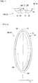
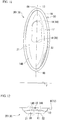
FIG. 3 is a diagram showing a backrest (backrest for a flat part) according to a first embodiment of the present invention, seen in an extending direction of a reference line. -
FIG. 4 is a front view of the backrest (backrest for the flat part) according to the first embodiment of the present invention. -
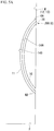
FIG. 5A is a diagram showing a state before the backrest (backrest for the flat part) according to the first embodiment of the present invention is used. -
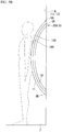
FIG. 5B is a diagram showing a state where the backrest (backrest for the flat part) according to the first embodiment of the present invention is being used. -
FIG. 6A is a diagram showing a modified example of the backrest (backrest for the flat part) according to the first embodiment of the present invention, which is a diagram showing a state before the backrest is used. -
FIG. 6B is a diagram showing a modified example of the backrest (backrest for the flat part) according to the first embodiment of the present invention, which is a diagram showing a state where the backrest is being used. -
FIG. 7A is a diagram showing a modified example of the backrest (backrest for the flat part) according to the first embodiment of the present invention, which is a diagram showing a state before the backrest is used. -
FIG. 7B is a diagram showing a modified example of the backrest (backrest for the flat part) according to the first embodiment of the present invention, which is a diagram showing a state where the backrest is being used. -
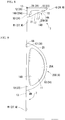
FIG. 8 is a diagram showing a backrest (backrest for a corner part) according to the first embodiment of the present invention, seen in an extending direction of a reference line. -
FIG. 9 is a front view of the backrest (backrest for the corner part) according to the first embodiment of the present invention. -
FIG. 10 is a diagram showing an installation example of the backrest (backrest for the corner part) according to the first embodiment of the present invention. -
FIG. 11 is a front view of a backrest according to a second embodiment of the present invention. -
FIG. 12 is a diagram showing the backrest according to the second embodiment of the present invention, seen in an extending direction of a reference line. -
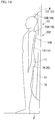
FIG. 13 is a diagram showing a state where the backrest according to the second embodiment of the present invention is being used. -
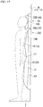
FIG. 14 is a diagram showing a backrest according to a third embodiment of the present invention. -
FIG. 15 is a diagram showing a modified example of the backrest according to the third embodiment of the present invention. -
FIG. 16 is a diagram showing a backrest according to a fourth embodiment of the present invention. -
FIG. 17 is a diagram showing a backrest according to a fifth embodiment of the present invention. - Hereinafter, a first embodiment of the present invention will be described with reference to the accompanying drawings.
- As shown in
FIG. 1 , a guide track transportation system T according to this embodiment includes avehicle 100 that transports passengers, and aguide track 70 on which thevehicle 100 travels. - The
guide track 70 includes a guidetrack road surface 90 which is approximately horizontally provided,side walls 91 that extend approximately upward from both ends of the guidetrack road surface 90 in a width direction,guide rails 80 that are provided on theside walls 91, andpower supply cables 81 that are provided integrally with theguide rail 80. - The guide rails 80 are provided on inner sides of the side walls 91 (on sides of the guide track road surface 90). The guide rails 80 are members that extend over the entire road length of the
guide track 70. The plurality ofpower supply cables 81 are provided on one of theside walls 91 at intervals in a vertical direction. Thepower supply cables 81 are provided over the entire road length of theguide track 70, similar to theguide rail 80. - The
vehicle 100 includes a box-shapedvehicle body 101, travelingwheels 102 that are provided under thevehicle body 101, guidewheels 103 that are provided in both side surface portions of thevehicle body 101, andpower collectors 104 that are provided in parallel with each other in the vertical direction with respect to theguide wheels 103. - The
guide wheels 103 are supported to be rotatable around vertical rotation shafts in the both side surface portions of thevehicle 100. Theguide wheels 103 are provided at approximately the same height position as that of the guide rails 80. Accordingly, when thevehicle 100 travels, theguide wheels 103 rotate being in contact with the guide rails 80. - The
power collectors 104 are in sliding contact with the above-mentionedpower supply cables 81. As thepower collectors 104 and thepower supply cables 81 are in sliding contact with each other, power supplied from thepower supply cables 81 is collected by thepower collectors 104. Thus, thevehicle 100 can travel on the guide track 70 (which will be described later). InFIG. 1 , an example of 3-phase AC in which threepower supply cables 81 are provided is shown. However, a case where DC (of two phases) is used as power, twopower supply cables 81 are provided. - Further, the
vehicle 100 is not limited to use in the above-described guide track transportation system T, but may be applied to any transport machine such as a railway or a bus. - As shown in
FIG. 2 , inside thevehicle body 101, a pair of side wall surfaces 1 that are provided vertically on a floor surface F, afront wall surface 2 and arear wall surface 3 that form a front portion and a rear portion of thevehicle 100 which are provided vertically on the floor surface F, seats S that are disposed in an internal space X formed by the pair of side wall surfaces 1, thefront wall surface 2, and therear wall surface 3, a device box M that accommodates devices or the like used in an operation of thevehicle 100, and a plurality ofbackrests 200 that are disposed on inner wall surfaces W of thevehicle 100 are provided. - The pair of side wall surfaces 1 includes at least one entrance E which is a doorway through which passengers get on and off, and a side window (not shown) provided in parallel to the entrance E. As the entrance E, for example, a single sliding door, double sliding doors, or the like are applied. A plurality of side windows are normally provided to capture external light into the internal space X of the
vehicle 100. In addition, in eachside wall surface 1, a surface disposed on the side of the internal space X of thevehicle 100 is provided with a decorative panel, or the like, and is formed in a side inner wall surface W1. - The
front wall surface 2 and therear wall surface 3 refer to end panels of thevehicle 100, and include a wall surface on a side where a driver's cab is disposed in the case of a lead vehicle. Gangway connections may be provided in the end panels, as necessary. Further, in thefront wall surface 2 and therear wall surface 3, surfaces disposed on the side of the internal space X of thevehicle 100 are provided with decorative panels or the like, and form a front inner wall surface W2 (partition wall surface W2 with respect to a driver's cab) and an end panel inner wall surface W3. In the following description, the side inner wall surfaces W1, the front inner wall surface W2, and the end panel inner wall surface W3 may be simply referred to as an inner wall surface W. - In the internal space X formed by the above-mentioned inner wall surface W, the seats S on which passengers sit are provided. In the
vehicle 100 according to this embodiment, the seats S includelong seats 4 of which seating surfaces are disposed along the side inner wall surfaces W1, and across seat 5 of which a seat surface is disposed in a direction intersecting the side inner wall surfaces W1. - The
long seats 4 are seats which are disposed along the side inner wall surfaces W1 of thevehicle 100, in which seat surfaces are continuous seats. In this embodiment, eachlong seat 4 is provided in an area between the pair of entrances E on the side inner wall surface W1. In end portions of eachlong seat 4, asleeve partition 6 is provided along a flat surface that intersects the traveling direction of thevehicle 100. Thesleeve partition 6 is a decorative panel or the like that is provided vertically above the floor surface F, and a handrail or the like to be grasped by passengers is provided in an upper portion thereof as necessary. Thesleeve partition 6 and the side inner wall surface W1 are disposed so as to intersect each other at an approximately right angle. The example ofFIG. 2 and the above description show an example of a configuration of the vehicle 100 (vehicle body 101), and the invention is not limited thereto. - In the internal space X of the
vehicle body 101 configured as described above, passengers sit on the seats S as necessary. On the other hand, there are passengers standing who do not sit on the seats S on crowded occasions. In thevehicle 100 according to this embodiment, for use of such standing passengers, thebackrests 200 are provided at a plurality of places. Thebackrests 200 are provided at several places of wall surfaces in the internal space X of thevehicle 100 in order to effectively and proactively use spaces having such sizes that it is difficult to dispose the seats S but it is possible to accommodate a standing passenger. As such a place, for example, acorner 7 formed by the above-mentionedsleeve partition 6 and the side inner wall surface W1, acorner 7 formed by the end panel inner wall surface W3 and the side inner wall surface W1, a rear surface (inner wall surface W) of thecross seat 5, a wall surface (inner wall surface W) of the device box M or the like, may be used. - In disposition of the
backrests 200 at thecorners 7, there are two forms. That is, one is a form in which an a part (abase member 10 which will be described later) of thebackrest 200 also serves as thesleeve partition 6 to form anew sleeve partition 6A, and the other is a form in which thebackrest 200 is disposed on asleeve partition 6B which is already provided. - In order to correspond to the plurality of places described above, the
backrests 200 according to this embodiment have two types, that is, abackrest 9 for a corner part and abackrest 8 for a flat part. Thebackrest 9 for the corner part is provided at thecorner 7, and thebackrest 8 for the flat part is provided on a flat portion of the inner wall surface W. - A configuration of the
backrest 8 for the flat part provided along a flat wall surface will be described with reference toFIGS. 3 to 5B . As shown inFIG. 3 , thebackrest 8 for the flat part includes thebase member 10 fixed to the inner wall surface W, and a retainingmember 11 provided on afront surface 14A of thebase member 10. - The
base member 10 is a member formed to be bent in an approximately circular arc shape in a sectional view. More specifically, as shown inFIG. 3 , the front surface of thebase member 10 opposite to the inner wall surface W has a concave shape in which the entirety thereof is smoothly recessed toward amain surface 12 when seen in an extending direction of areference line 13. - Further, as shown in
FIGS. 5A and5B , thebase member 10 is formed so that it is bent to be convex from the inner wall surface W in a direction from an upper side to a lower side along the direction of thereference line 13, in a cross-sectional view intersecting thereference line 13. Both edges of thebase member 10 in a vertical direction are formed in a shape corresponding to the inner wall surface W of thevehicle body 101 to form anattachment portion 38. In a state where theattachment portion 38 is in contact with the inner wall surface W, thebase member 10 is attached to the inner wall surface W. - Here, the inner wall surface W extends approximately along the
main surface 12 including thereference line 13 that extends in the direction intersecting the floor surface F. Accordingly, thebase member 10 is provided in a state of being along themain surface 12. - Further, the retaining
member 11 is provided on thefront surface 14A placed on a side opposite to theattachment portion 38 in thebase member 10. The thickness of the retainingmember 11 is approximately uniform along thefront surface 14A of thebase member 10. In addition, the retainingmember 11 is formed of a material capable of being elastically deformed, to thereby serve as a cushion to ease a hard feeling when passengers lean thereon. As such a material, for example, urethane foam or a foamable resin material such as sponge may be considered. - A
front surface 14B of the retainingmember 11 has a curved shape along thefront surface 14A of thebase member 10. Specifically, thefront surface 14B of the retainingmember 11 is formed in a concave shape in which the entirety thereof is smoothly recessed toward themain surface 12 when seen in the extending direction of thereference line 13, and is formed in a shape that protrudes while being bent in a direction away from themain surface 12 when seen in the direction intersecting thereference line 13. More specifically, when seen in the extending direction of thereference line 13, thefront surface 14B of the retainingmember 11 is formed by a firstcurved surface 21 and a secondcurved surface 22 that extend in different directions with the above-mentionedreference line 13 being interposed therebetween. The firstcurved surface 21 and the secondcurved surface 22 are curved surfaces formed to be bent toward the attachment portion 38 (main surface 12) when seen in the extending direction of thereference line 13. The firstcurved surface 21 and the secondcurved surface 22 are continuously formed to form a single curved shape. Thus, thefront surface 14B of the retainingmember 11 is formed in a concave shape in which the entirety thereof is smoothly recessed toward themain surface 12. - Further, as shown in
FIG. 4 , ahook 50 from which a passenger hangs baggage, or the like, may be provided on thebackrest 200. Thehook 50 is provided on an outer surface of thebase member 10. On the outer surface of thebase member 10, a hook storage (not shown) provided to be recessed inward is formed. Thehook 50 in an unused state is configured to be stored in the hook storage. More specifically, thehook 50 is supported by a pin or the like provided in the hook storage. Thus, thehook 50 is rotatable around the pin. When using thehook 50, a passenger rotates and pulls out thehook 50. In addition, it is preferable that thehook 50 in the storage state is formed to be flushed with the outer surface of thebase member 10. It may be not essential that thehook 50 is stored in thebase member 10. - According to such a configuration, since baggage or the like can be hung from the
hook 50, it is possible to further reduce the burden of standing passengers. That is, it is possible to further enhance habitability of thevehicle 100. - With respect to the
backrest 8 for the flat part formed as described above, a passenger leans back while retaining the passenger's back thereon (seeFIG. 5B ). Thus, it is possible to stably support load of a standing passenger. Particularly, since the retainingmember 11 is formed of an elastic material, it is possible to give excellent ride comfort to a passenger, compared with a case where the passenger directly leans on a hard wall surface. - Here, as shown in
FIGS. 6A and6B , in a cross-sectional view seen in the direction intersecting thereference line 13, the retainingmember 11 may be formed to be greater than the thickness of thebase member 10, and thefront surface 14B of the retainingmember 11 may be formed to have a curved shape which is convex shape from thefront surface 14A of thebase member 10. Here, thefront surface 14A of thebase member 10 may be formed to be recessed toward the inner wall surface W as shown inFIGS. 6A and6B , but the invention is not limited thereto. That is, thefront surface 14A may be formed to be convex toward the inner wall surface W, or may be formed in a flat shape which is parallel to the inner wall surface W. - In a case where a passenger leans on the retaining
member 11, the retainingmember 11 is slightly deformed as shown inFIG. 6B . Specifically, the retainingmember 11 is deformed so that unevenness that follows up the shape of the passenger's body is formed on thefront surface 14B. In this way, since the retainingmember 11 is formed of a material capable of being elastically deformed, the retainingmember 11 serves as a cushion that eases a hard feeling when the passenger leans. As such a material, for example, urethane foam or a foamable resin material such as sponge may be considered. - The retaining
member 11 may be configured to be greatly elastically deformed to wrap the passenger's body. In this case, as shown inFIGS. 7A and7B , thefront surface 14A of the retainingmember 11 may be formed in a flat shape which is parallel to the inner wall surface W. In a case where a passenger leans on the retainingmember 11, the retainingmember 11 greatly deforms along a surface shape of the passenger's body as shown inFIG. 7B . - According to such a configuration, in a state where a passenger does not use the
backrest 200, that is, in a state where load is removed from the retainingmember 11, thefront surface 14B of the retainingmember 11 forms a shape (initial shape) along thefront surface 14A of thebase member 10 by an elastic restoring force thereof. Accordingly, in a situation where a passenger does not use thebackrest 200, since the retainingmember 11 restores the initial shape by the elastic restoring force, it is possible to enhance aesthetics of thebackrest 200. - On the other hand, in a state where a passenger uses the
backrest 200, that is, in a state where load is added to the retainingmember 11, the retainingmember 11 is greatly deformed to wrap the passenger's body, to thereby make it possible to offer a retaining feeling to the passenger. Further, according to such a configuration, the retainingmember 11 may exhibit various curved shapes according to physiques of passengers. - Subsequently, a configuration of the
backrest 9 for the corner part will be described with reference toFIGS. 8 to 10 . In thebackrest 9 for the corner part, thebase member 10 is formed in a curved shape along thecorner 7, when seen in the extending direction of thereference line 13. More specifically, thebase member 10 includes afirst base member 23 provided on afirst wall surface 26 which is thesleeve partition 6, for example, and asecond base member 24 that extends in a direction intersecting thefirst base member 23. Thesecond base member 24 is formed along the side inner wall surface W1 that extends to intersect thesleeve partition 6. - Hereinafter, an example in which the
first base member 23 also serves as thesleeve partition 6, and thus, thefirst base member 23 and thesleeve partition 6 are integrally formed to form thenew sleeve partition 6A will be described. However, the form of thefirst base member 23 is not limited thereto, and thefirst base member 23 and thesleeve partition 6 may be formed as separate bodies. In other words, a configuration in which thefirst base member 23 is attached to an existingsleeve partition 6B may be adopted. - The
first base member 23 according to this embodiment is formed in an approximately D shape in an external view, as shown inFIG. 9 , to serve as a partition between thelong seat 4 and the entrance E. Specifically, thefirst base member 23 and thesecond base member 24 are disposed so that long sides thereof overlap each other in thecorner 7 which is formed by thefirst wall surface 26 and thesecond wall surface 27. Using these long sides as chords,curve portions 25 that extend in an approximately arc shape are respectively formed. - It is preferable that the
first base member 23 and thesecond base member 24 are integrally formed of a resin material or the like. According to such a configuration, it is possible to simplify a manufacturing process. - Further, an area formed between the
respective curve portions 25 in thefirst base member 23 and thesecond base member 24 is bent from an upper side to a lower side along the direction of thereference line 13, to thereby form asupport surface 25A. That is, thebase member 10 is formed by changing a curvature of an arc corresponding to thecurve portion 25 that uses the above-mentioned long sides as the chords between thefirst wall surface 26 and thesecond wall surface 27 so that the entirety thereof is smoothly recessed along thecorner 7 when seen in the extending direction of thereference line 13, and a front surface thereof becomes thesupport surface 25A. An outer surface of thesupport surface 25A is formed as thefront surface 14A of thebase member 10. Further, in a cross-sectional view (not shown) including the retainingmember 11 of thebase member 10, the base member may have a hollow shape or a solid shape. - The retaining
member 11 is provided on thefront surface 14A of thebase member 10. Similar to thebackrest 8 for the flat part, the thickness of the retainingmember 11 is approximately uniform along thefront surface 14A of thebase member 10. Further, the retainingmember 11 is formed of a material capable of being elastically deformed to serve as a cushion that eases a hard feeling when a passenger leans thereon. As such a material, for example, urethane foam or a foamable resin material such as sponge may be considered. - The
front surface 14B of the retainingmember 11 has a curved shape along thefront surface 14A of thebase member 10. Specifically, thefront surface 14B of the retainingmember 11 is formed in a concave shape in which the entirety thereof is smoothly recessed toward the main surface when seen in the extending direction of thereference line 13, and is formed in a shape that protrudes while being bent toward a direction away from themain surface 12 when seen in the direction intersecting thereference line 13. More specifically, when seen in the extending direction of thereference line 13, the retainingmember 11 includes a firstcurved surface 21 provided along thefront surface 14A on the side of thefirst base member 23, and a secondcurved surface 22 provided along thefront surface 14A on the side of thesecond base member 24. Both of the firstcurved surface 21 and the secondcurved surface 22 are curved surfaces formed to be bent toward the attachment portion 38 (main surface 12) in the extending direction of thereference line 13. The firstcurved surface 21 and the secondcurved surface 22 are continuously formed to form a single curved surface. Thus, thefront surface 14 of the retainingmember 11 exhibits a concave shape in which the entirety thereof is smooth toward themain surface 12. - A sectional view of the
backrest 9 for the corner part including the retaining member seen in the direction intersecting thereference line 13 is approximately the same as the sectional view of thebackrest 8 for the flat part shown inFIG. 5A , but the invention is not limited thereto. For example, the thickness of the retainingmember 11 may be formed to be greater than the thickness of thebase member 10, such as thebackrest 8 for the flat part shown inFIG. 6A , and thefront surface 14B of the retainingmember 11 may be formed to have a curved shape such as a convex shape from thefront surface 14A of thebase member 10. - When seen in the extending direction of the
reference line 13, an extending dimension of thesecond base member 24 is set to be shorter than an extending dimension of thefirst base member 23. Thus, even in a place where a space is limited, thesecond base member 24 may be disposed with no problem. - The
backrest 9 for the corner part formed as described above is disposed at a position of such a height that anupper edge 8A of the inner wall surface W is approximately disposed at the height of the passenger's shoulders and alower edge 8B is approximately disposed at the height of the passenger's legs, for example. A passenger leans back while retaining the back on thebackrest 9 for the corner part disposed as described above. More specifically, the passenger leans back so that the back approximately directs towards thecorner 7. Particularly, since the retainingmember 11 is formed of an elastic material, it is possible to provide excellent ride comfort to a passenger, compared with a case where the passenger directly leans on a hard wall surface. - Hereinbefore, the embodiment of the invention has been described in detail with reference to the accompanying drawings, but a specific configuration is not limited to the embodiment, and design modifications or the like may be included in a range without departing from the scope of the invention.
- For example, places where the
backrests 200 are provided are not limited to the above-described embodiment. As shown inFIG. 2 , thebackrests 200 may be applied to various places in thevehicle body 101. Specifically, the following places may be considered. - For example, the
first wall surface 26 may be the end panel inner wall surface W3 of thevehicle 100, and thesecond wall surface 27 may be the side inner wall surface W1 of thevehicle 100. Further, thefirst wall surface 26 may be the front inner wall surface W2, and thesecond wall surface 27 may be the side inner wall surface W1. Furthermore, thefirst wall surface 26 may be the wall surface W of the device box provided in thevehicle 100, and thesecond wall surface 27 may be the side inner wall surface W1. In addition, it may be considered that thebackrest 200 is applied to the inner wall surface W in a multipurpose space P such as a wheelchair space provided in thevehicle 100. Further, inFIG. 2 , a configuration in which thebackrest 9 for the corner part is provided at one end portion of thelong seat 4 is shown. However, thebackrest 9 for the corner part may be provided at each of both end portions of thelong seat 4. - Subsequently, a second embodiment of the invention will be described with reference to
FIGS. 11 to 13 . Abackrest 201 according to this embodiment has a configuration different from the above-described first embodiment in the following points. In thebackrest 201 according to this embodiment, unevenness that follows up the shape of the passenger's body is formed on afront surface 14B of a retainingmember 11. Specifically, as shown inFIG. 12 , thefront surface 14B of the retainingmember 11 is formed by a firstcurved surface 21 and a secondcurved surface 22 that extend in different directions with the above-describedreference line 13 being interposed therebetween. The firstcurved surface 21 and the secondcurved surface 22 are curved surfaces formed to be bent toward the attachment portion 38 (main surface 12) when seen in the extending direction of thereference line 13. The firstcurved surface 21 and the secondcurved surface 22 are continuously formed to form a single curved shape. Thus, thefront surface 14B of the retainingmember 11 is formed in a concave shape in which the entirety thereof is smoothly recessed toward themain surface 12. - Further, as shown in
FIG. 13 , aconcave portion 17 that is recessed in a direction approaching themain surface 12 from thefront surface 14B is formed in the retainingmember 11 when seen in the direction intersecting thereference line 13. In addition, at least oneconvex portion 18 that is provided along the extending direction of thereference line 13 in parallel to theconcave portion 17 and protrudes in a direction away from the base member 10 (main surface 12) is formed on thefront surface 14B of the retainingmember 11. In this embodiment, twoconvex portions concave portion 17 and theconvex portions 18 may be suitably designed to approximately follow up a curve from the waist to the buttocks of the passenger's body. For example, in this embodiment, a firstconvex portion 19 formed to follow up the waist and a secondconvex portion 20 formed to follow up the buttocks are formed in the order from an upper side to a lower side of the retainingmember 11. - A passenger leans back while holding the passenger's back on the
backrest 201 configured as described above. Here, the wrist and the buttocks of the passenger are supported by the firstconvex portion 19 and the secondconvex portion 20, and the entirety of a back part is supported by theconcave portion 17. That is, the shape of thefront surface 14B of the retainingmember 11 corresponds to the body's shape, to thereby assign the hold feeling to the passenger. Thus, it is possible to stably support the load of the standing passenger. Particularly, since the retainingmember 11 is formed of an elastic material, it is possible to provide excellent ride comfort to a passenger, compared with a case where the passenger directly leans on a hard wall surface. - In addition, as described above, the
front surface 14B of the retainingmember 11 is formed in a concave shape by the firstcurved surface 21 and the secondcurved surface 22 when seen in the extending direction of thereference line 13. Thus, it is possible to stably retain the passenger's body on both sides in the lateral direction. Accordingly, for example, even in a case where shake or vibration of thevehicle 100 occurs, a passenger does not easily break the posture. Further, even though an extra force for maintaining the posture is not given, it is possible to resist such shake or vibration. - The
backrest 201 having the above-described configuration may be applied to any one of thebackrest 8 for the flat part and thebackrest 9 for the corner part. - Here, for example, in the above-described embodiment, a configuration in which the retaining
member 11 is formed in advance in a curved shape corresponding to the shape of the body and constantly maintains the curved surface is shown. However, the form of the retainingmember 11 is not limited thereto, and may be elastically deformed similar to the first embodiment, and may be formed of a material having a sufficient elastic restoring force. - According to such a configuration, in a state where a passenger does not use the
backrest 201, that is, in a state where load is removed from the retainingmember 11, thefront surface 14B of the retainingmember 11 forms a shape (initial shape) along thefront surface 14A of thebase member 10 by an elastic restoring force thereof. Accordingly, in a situation where the passenger does not use thebackrest 201, since the retainingmember 11 restores the initial shape by the elastic restoring force, it is possible to enhance aesthetics of thebackrest 201. On the other hand, in a state where a passenger uses thebackrest 201, that is, in a state where load is applied to the retainingmember 11, the retainingmember 11 is greatly deformed to wrap the passenger's body, to thereby make it possible to assign a hold feeling to the passenger. Further, according to such a configuration, the retainingmember 11 may offer various curved shapes according to physiques of passengers. Particularly, it is possible to form theconcave portion 17 or theconvex portion 18 at different positions according to heights of adults or children. Thus, it is possible to enhance habitability for many passengers. - Further, a thin film coating material that covers the
front surface 14B of the retainingmember 11 may be provided. It is preferable that the coating material has a sufficient fractional force with respect to the passenger's skin or clothes, for example. For example, a configuration in which a coating material subjected to satin finishing or groove cutting covers the retainingmember 11 may be used. In addition, a configuration in which the same surface processing is directly performed with respect to thefront surface 14B of the retainingmember 11 to enhance a frictional force may be used. - According to such a configuration, even in a case where vibration or shake occurs in the
vehicle 100, thebackrest 200 can more stably retain the passenger's body. - In addition, in the form in which the retaining
member 11 is formed of an elastic restoring force, a configuration in which a curved shaped core material having the firstcurved surface 21, the secondcurved surface 22, and theconcave portion 17 and theconvex portions 18 as described above is provided in the retainingmember 11 may be employed. As the core material, for example, a plate-shaped resin material that has a curved shape and is integrally molded, or the like, may be considered. According to such a configuration, as a passenger leans back, the retainingmember 11 is elastically deformed along the curved shape of the core material. Thus, it is possible to enhance aesthetics, and to obtain excellent habitability for passengers. - According to such a configuration, it is possible to effectively and proactively utilize places where it is difficult to dispose the seats S as spaces that accommodate standing passengers.
- Subsequently, a third embodiment of
backrests FIGS. 14 and15 . Thebackrests backrests headrest 33 for supporting the passenger's head. - The
headrest 33 is formed by providing the above-described two convex portions 18 (the firstconvex portion 19 and the second convex portion 20), a thirdconvex portion 33A, and a fourthconvex portion 33B, on thefront surface 14B of the retainingmember 11. The thirdconvex portion 33A and the fourthconvex portion 33B are disposed at intervals along the extending direction of thereference line 13 on an upper side with reference to the firstconvex portion 19 and the secondconvex portion 20. In a case where a passenger uses theheadrest 33, as shown inFIG. 14 , the thirdconvex portion 33A follows up the passenger's neck, and the fourthconvex portion 33B follows up an upper portion of the head of the passenger. Thus, the thirdconvex portion 33A and the fourthconvex portion 33B function as theheadrest 33 by retaining the passenger's head to wrap the head. Theheadrest 33 may be disposed on an upper side with a gap from an upper end portion of the backrest 202 (see thebackrest 203 inFIG. 15 (which will be described later)), or may be formed integrally with thebackrest 202. InFIG. 14 , an example in which theheadrest 33 and thebackrest 202 are integrally formed is shown. - On the other hand,
FIG. 15 shows an example in which theheadrest 33 and thebackrest 203 are individually configured. In this case, theheadrest 33 has only different dimensions of respective portions thereof compared with thebackrest 203, and is formed using the same configuration and members as in thebackrest 203. That is, in the example ofFIG. 15 , it can be said that the backrest is divided into two parts along the extending direction of thereference line 13. - According to such a configuration, it is possible to stably support the passenger's head, and thus, it is possible to withstand use under an environment that higher stability is necessary, such as a train that travels at high speed, for example.
- Subsequently, a fourth embodiment of a
backrest 204 according to the invention will be described with reference toFIG. 16 . Thebackrest 204 according to this embodiment is different from the above-described embodiments in the following points. In thebackrest 204 according to this embodiment, a plurality of rod-shapedmembers 34 formed so that both end portions thereof are fixed to the inner wall surface W and a space between the both end portions is bent is used asbase members 10. Further, as the retainingmember 11, a fabric material bridged between the rod-shapedbase members 10 is used. - The rod-shaped
member 34 may be formed by bending a circular tube member or the like made of metal, for example, into an arc shape. In the state of being installed on the inner wall surface W, the plurality of rod-shapedmembers 34 are approximately parallel to each other. Further, the size of separation between the rod-shapedmembers 34 is set to be sufficiently larger than the width of the passenger's body. The respective end portions of the rod-shapedmembers 34 are respectively fixed to fourfixation positions 35 on the inner wall surface W using fixing members (not shown). A rectangular area formed by connecting the fourfixation positions 35 with straight lines forms themain surface 12 on the inner wall surface W. - As described above, the retaining
member 11 is provided on thebase members 10 configured by two rod-shapedmembers 34. Specifically, the retainingmember 11 is bridged along curved shapes offront surfaces 14A (outer peripheral surfaces) of the rod-shapedmembers 34 which are thebase members 10. When attaching the retainingmember 11 to the base members 10 (the rod-shaped members 34), a method of providing a winding margin to each of both edges 37 in the width direction of the retainingmember 11 and wrapping the winding margin along the outer peripheral surface of each rod-shapedmember 34 may be considered as an example. The winding margin wrapped around the rod-shapedmember 34 may be sewn to the retainingmember 11 to be firmly fixed. - When fixing the
base members 10 and the retainingmember 11, a configuration in which a separate fixing member (not shown) is provided between the two members may be used. Specifically, the fixing member is a member formed to be bent along thefront surface 14A (outer peripheral surface) of the base member 10 (rod-shaped member 34). By providing the fixing member, it is possible to stably retain the curved shape of the retainingmember 11. - Further, the retaining
member 11 is integrally formed of a stretchable fiber-based material. As a form of the stretchable fiber-based material, a fabric obtained by weaving elastic fibers, which has elasticity in an extending direction of the fabric, or a fabric obtained by stereoscopically weaving elastic fibers, which has elasticity in a thickness direction of the fabric in addition to an extending direction thereof may be considered as a specific example. Further, polyester or the like may be used as the fibers. - When using the
backrest 204 configured in this way, a passenger leaves himself or herself on the retainingmember 11, to thereby make it possible to maintain a stable posture even in a standing state. More specifically, the retainingmember 11 formed of an elastic fiber-based material is stretched corresponding to a body's shape to form a curved shape, and thus, it is possible to dispersedly support load of a passenger. Thus, a passenger can be given excellent ride comfort. In addition, with a simple structure, it is possible to simplify a manufacturing process, and to enhance aesthetics inside thevehicle 100. - In the above-described description, an example in which the fiber-based material such as cloth is used as the retaining
member 11 is shown. However, the form of the retainingmember 11 is not limited thereto, and for example, a resin material such as vinyl formed in a sheet shape, or a natural material such as leather may be used, for example. With such a configuration, the retainingmember 11 follows up a curved shape of the body, to make it possible to provide an excellent comfort ride to a passenger. - Further, the curved shape of the base member 10 (rod-shaped member 34) is not limited to the above-mentioned circular arc shape, and the curved shape may be formed so that its bending is gradually enlarged, for example, from the top to the bottom in a state of being attached to the inner wall surface W. According to such a shape, when a passenger leans back, it is possible to more stably retain the body by supporting load from below in an inclined direction.
- Next, a fifth embodiment of the invention will be described with reference to
FIG. 17 . As shown inFIG. 17 , apartitioning portion 40 is provided as a retainingmember 11 in abackrest 205 according to this embodiment. The partitioningportion 40 is disposed in an area under theconcave portion 17 on thefront surface 14B of the retainingmember 11. More specifically, the partitioningportion 40 is provided to smoothly protrude from thefront surface 14A of thebase member 10. Further, the dimension of thepartitioning portion 40 in the extending direction of thereference line 13 is set to be approximately the same as the dimension of the passenger's legs. - According to such a configuration, when a passenger leans on the
backrest 205, it is possible to interpose thepartitioning portion 40 between both legs. Thus, thebackrest 205 can more stably retain the passenger's body in a lateral direction. - According to the above-described backrests, it is possible to provide a guide track transportation system that enhances habitability and aesthetics inside a vehicle.
-
- 1
- side wall surface
- 2
- front wall surface
- 3
- rear wall surface
- 4
- long seat
- 5
- cross seat
- 6
- sleeve partition
- 7
- corner
- 8
- backrest for flat part
- 9
- backrest for corner part
- 10
- base member
- 11
- retaining member
- 12
- main surface
- 13
- reference line
- 14
- front surface
- 17
- concave portion
- 18
- convex portion
- 19
- first convex portion
- 20
- second convex portion
- 21
- first curved surface
- 22
- second curved surface
- 23
- first base member
- 24
- second base member
- 25
- curve portion
- 25A
- support surface
- 26
- first wall surface
- 27
- second wall surface
- 33
- headrest
- 33A
- third convex portion
- 33B
- fourth convex portion
- 34
- rod-shaped member
- 35
- fixation position
- 36
- outline
- 37
- both edges
- 38
- attachment portion
- 40
- partitioning portion
- 50
- hook
- 70
- guide track
- 80
- guide rail
- 81
- power supply cable
- 90
- track road surface
- 91
- side wall
- 100
- vehicle
- 101
- vehicle body
- 102
- wheel
- 103
- guide wheel
- 104
- power collector
- 200,201,202,203,204,205
- backrest
- E
- entrance
- F
- floor surface
- M
- device box
- P
- multipurpose space
- S
- seat
- T
- guide track transportation system
- W
- inner wall surface
- W1
- side inner wall surface
- W2
- front inner wall surface
- W3
- end panel inner wall surface
- X
- internal space
Claims (17)
- A backrest for supporting load of a standing passenger, the backrest comprising:a base member that is provided along a main surface including a reference line that extends in a direction that intersects a floor surface of a vehicle; anda retaining member that is provided on a front surface of the base member and has a front surface of a curved shape in a state of supporting the load in a direction toward the front surface.
- The backrest according to claim 1,
wherein the front surface of the retaining member is formed in a concave shape having a first curved surface and a second curved surface that extend in different directions with the reference line being interposed therebetween, when seen in an extending direction of the reference line. - The backrest according to claim 1 or 2,
wherein the front surface of the retaining member is formed in a convex shape that protrudes in a direction away from the main surface, when seen in a direction that intersects the reference line. - The backrest according to any one of claims 1 to 3,
wherein the retaining member includes a concave portion that is recessed in a direction approaching the front surface of the base member, when seen in the direction that intersects the reference line. - The backrest according to claim 4,
wherein the retaining member includes at least one convex portion that protrudes in the direction away from the front surface of the base member, when seen in the direction that intersects the reference line, and is disposed along the extending direction of the reference line in parallel to the concave portion. - The backrest according to claim 4 or 5,
wherein the retaining member further includes a partitioning portion that extends along the reference line in an area which is close to the floor surface with reference to the concave portion and protrudes in the direction away from the front surface of the base member. - The backrest according to any one of claims 1 to 6,
wherein the retaining member is formed of a material that enables the front surface thereof to maintain the curved shape in a state where the load is removed. - The backrest according to any one of claims 1 to 6,
wherein the retaining member is formed of a material having an elastic restoring force and restores an initial shape different from the curved shape in a state where the load is removed. - The backrest according to any one of claims 1 to 8,
wherein the retaining member is formed of a stretchable fiber-based material. - A vehicle comprising the backrest according to any one of claims 1 to 9,
wherein the base member is integrally or separately provided on a wall surface in the vehicle that extends along the main surface. - The vehicle according to claim 10,
wherein the wall surface includes a first wall surface and a second wall surface that form a corner by intersecting each other. - The vehicle according to claim 11,
wherein the first wall surface is a sleeve partition of the vehicle, and the second wall surface is a side inner wall surface of the vehicle. - The vehicle according to claim 11,
wherein the first wall surface is an end panel inner wall surface of the vehicle, and the second wall surface is a side inner wall surface of the vehicle. - The vehicle according to claim 11,
wherein the first wall surface is a partition wall surface with respect to a driver's cab of the vehicle, and the second wall surface is a side inner wall surface of the vehicle. - The vehicle according to claim 11,
wherein the first wall surface is a wall surface of a device box provided in the vehicle, and the second wall surface is a side inner wall surface of the vehicle. - The vehicle according to claim 10,
wherein the wall surface is an inner wall surface in a multipurpose space provided in the vehicle. - A guide track transportation system comprising:the vehicle according to any one of claims 10 to 16; anda guide track on which the vehicle travels.
Applications Claiming Priority (2)
| Application Number | Priority Date | Filing Date | Title |
|---|---|---|---|
| JP2014199645A JP5909268B1 (en) | 2014-09-30 | 2014-09-30 | Backrest, vehicle, and guided track traffic system |
| PCT/JP2015/075421 WO2016052094A1 (en) | 2014-09-30 | 2015-09-08 | Backrest, vehicle, and guide track transportation system |
Publications (2)
| Publication Number | Publication Date |
|---|---|
| EP3184396A1 true EP3184396A1 (en) | 2017-06-28 |
| EP3184396A4 EP3184396A4 (en) | 2017-09-13 |
Family
ID=55630137
Family Applications (1)
| Application Number | Title | Priority Date | Filing Date |
|---|---|---|---|
| EP15847399.1A Withdrawn EP3184396A4 (en) | 2014-09-30 | 2015-09-08 | Backrest, vehicle, and guide track transportation system |
Country Status (7)
| Country | Link |
|---|---|
| US (1) | US20170210324A1 (en) |
| EP (1) | EP3184396A4 (en) |
| JP (1) | JP5909268B1 (en) |
| KR (1) | KR20170043596A (en) |
| CN (1) | CN106794849A (en) |
| TW (1) | TW201632383A (en) |
| WO (1) | WO2016052094A1 (en) |
Families Citing this family (4)
| Publication number | Priority date | Publication date | Assignee | Title |
|---|---|---|---|---|
| CN107650932B (en) * | 2017-11-09 | 2024-02-06 | 中唐空铁集团有限公司 | Cladding type seat back structure |
| JP7059065B2 (en) * | 2018-03-27 | 2022-04-25 | 株式会社総合車両製作所 | Railroad vehicle |
| JP7827511B2 (en) * | 2022-03-24 | 2026-03-10 | 日本車輌製造株式会社 | Vehicle hip rest |
| JP7611439B1 (en) | 2024-02-20 | 2025-01-09 | 日本車輌製造株式会社 | Vehicle hip rest |
Family Cites Families (12)
| Publication number | Priority date | Publication date | Assignee | Title |
|---|---|---|---|---|
| CH664502A5 (en) * | 1985-09-17 | 1988-03-15 | Giovanola Freres Sa | PASSENGER RESTRAINT IN STANDING POSITION ON VEHICLE ON RAILS. |
| JP3586300B2 (en) * | 1994-11-12 | 2004-11-10 | 天龍工業株式会社 | Standing seat |
| ATE211713T1 (en) * | 1997-08-28 | 2002-01-15 | Crown Equip Corp | DRIVER'S STATION FOR INDUSTRIAL TRUCK WITH SEATING ADJUSTABLE IN THREE POSITIONS |
| DE19814548C1 (en) * | 1998-04-01 | 1999-07-22 | Schimmelpfennig Karl Heinz | Seat for passenger vehicle |
| JP2000043719A (en) * | 1998-07-30 | 2000-02-15 | Hitachi Ltd | Train car |
| DE10008259B4 (en) * | 2000-02-23 | 2005-03-10 | Deutsche Lufthansa | Aircraft passenger cabin with at least one passenger support device |
| US6948739B2 (en) * | 2003-07-22 | 2005-09-27 | Crown Equipment Corporation | Operator support pad for a vehicle |
| JP4628976B2 (en) * | 2006-02-28 | 2011-02-09 | 財団法人鉄道総合技術研究所 | Multipurpose storage device for railway vehicles |
| JP4927610B2 (en) * | 2007-03-14 | 2012-05-09 | 公益財団法人鉄道総合技術研究所 | Vehicle wall surface support device |
| US7523993B1 (en) * | 2007-11-23 | 2009-04-28 | Nova Bus, Division De Groupe Volvo Canada Inc. | Passenger dorsal support |
| DE102010054942A1 (en) * | 2010-12-17 | 2012-06-21 | Airbus Operations Gmbh | Space-optimized cabin attendant seat for aircraft |
| EP2851256B1 (en) * | 2013-09-18 | 2019-02-06 | Bombardier Transportation GmbH | A passenger cabin of a vehicle and a method of manufacturing a passenger cabin |
-
2014
- 2014-09-30 JP JP2014199645A patent/JP5909268B1/en not_active Expired - Fee Related
-
2015
- 2015-09-08 WO PCT/JP2015/075421 patent/WO2016052094A1/en not_active Ceased
- 2015-09-08 KR KR1020177007268A patent/KR20170043596A/en not_active Withdrawn
- 2015-09-08 EP EP15847399.1A patent/EP3184396A4/en not_active Withdrawn
- 2015-09-08 CN CN201580052720.5A patent/CN106794849A/en active Pending
- 2015-09-08 US US15/515,139 patent/US20170210324A1/en not_active Abandoned
- 2015-09-18 TW TW104130960A patent/TW201632383A/en unknown
Also Published As
| Publication number | Publication date |
|---|---|
| JP2016068737A (en) | 2016-05-09 |
| KR20170043596A (en) | 2017-04-21 |
| EP3184396A4 (en) | 2017-09-13 |
| US20170210324A1 (en) | 2017-07-27 |
| CN106794849A (en) | 2017-05-31 |
| JP5909268B1 (en) | 2016-04-26 |
| WO2016052094A1 (en) | 2016-04-07 |
| TW201632383A (en) | 2016-09-16 |
Similar Documents
| Publication | Publication Date | Title |
|---|---|---|
| US20170210324A1 (en) | Backrest, vehicle, and guide track transportation system | |
| US9216674B1 (en) | Portable seat partition unit | |
| US10589864B2 (en) | Multifunctional support rail | |
| US20150013072A1 (en) | Travel Pillow | |
| EP3863889B1 (en) | Vehicle seating | |
| CN103261024A (en) | Space optimized cabin attendant standing seat for aircraft | |
| US20180022248A1 (en) | Armrest | |
| JP5847382B2 (en) | Passenger car for night bus | |
| RU2252156C2 (en) | Suspended seat with fastening on pillar of passenger vehicle body load-bearing structure | |
| CN105555633A (en) | A passenger cabin of a vehicle and a method of manufacturing a passenger cabin | |
| WO2017118868A1 (en) | Passenger seat comprising tiltable sections of its headrest | |
| JP2021526447A (en) | Shaking carriage table | |
| EP2578447B1 (en) | Retaining device for passenger transport vehicle and passenger transport vehicle comprising such a device | |
| JP2012171498A (en) | Vehicle indoor structure and vehicle seat | |
| KR101273706B1 (en) | Cushion adjusting apparatus for back frame of seat of vehicle | |
| JP5164099B2 (en) | Railway vehicle | |
| EP2578441B1 (en) | Seat for passenger transport vehicle and passenger transport vehicle comprising such a seat | |
| US20130270886A1 (en) | Interior structure of automobile having a leg rest at the front passenger seat | |
| JP3184966U (en) | Seat cushion | |
| CN204801801U (en) | Railway carriage and passenger train | |
| JP3159029U (en) | Car | |
| CN104816654B (en) | A fixed neck support pillow | |
| CN104973083A (en) | Passenger train carriage and passenger train | |
| KR102523395B1 (en) | Folding rotating seat | |
| JP3154776U (en) | Car |
Legal Events
| Date | Code | Title | Description |
|---|---|---|---|
| PUAI | Public reference made under article 153(3) epc to a published international application that has entered the european phase |
Free format text: ORIGINAL CODE: 0009012 |
|
| 17P | Request for examination filed |
Effective date: 20170323 |
|
| AK | Designated contracting states |
Kind code of ref document: A1 Designated state(s): AL AT BE BG CH CY CZ DE DK EE ES FI FR GB GR HR HU IE IS IT LI LT LU LV MC MK MT NL NO PL PT RO RS SE SI SK SM TR |
|
| AX | Request for extension of the european patent |
Extension state: BA ME |
|
| A4 | Supplementary search report drawn up and despatched |
Effective date: 20170814 |
|
| RIC1 | Information provided on ipc code assigned before grant |
Ipc: B60N 2/64 20060101ALI20170808BHEP Ipc: B61D 1/04 20060101ALI20170808BHEP Ipc: B61D 37/00 20060101AFI20170808BHEP Ipc: A47C 16/00 20060101ALI20170808BHEP |
|
| DAV | Request for validation of the european patent (deleted) | ||
| DAX | Request for extension of the european patent (deleted) | ||
| STAA | Information on the status of an ep patent application or granted ep patent |
Free format text: STATUS: THE APPLICATION IS DEEMED TO BE WITHDRAWN |
|
| 18D | Application deemed to be withdrawn |
Effective date: 20180313 |