EP3184309A1 - Inkjet printer and method of checking liquid feeding state - Google Patents
Inkjet printer and method of checking liquid feeding state Download PDFInfo
- Publication number
- EP3184309A1 EP3184309A1 EP16201862.6A EP16201862A EP3184309A1 EP 3184309 A1 EP3184309 A1 EP 3184309A1 EP 16201862 A EP16201862 A EP 16201862A EP 3184309 A1 EP3184309 A1 EP 3184309A1
- Authority
- EP
- European Patent Office
- Prior art keywords
- ink
- tank
- head
- pressure
- inkjet printer
- Prior art date
- Legal status (The legal status is an assumption and is not a legal conclusion. Google has not performed a legal analysis and makes no representation as to the accuracy of the status listed.)
- Granted
Links
Images




Classifications
-
- B—PERFORMING OPERATIONS; TRANSPORTING
- B41—PRINTING; LINING MACHINES; TYPEWRITERS; STAMPS
- B41J—TYPEWRITERS; SELECTIVE PRINTING MECHANISMS, i.e. MECHANISMS PRINTING OTHERWISE THAN FROM A FORME; CORRECTION OF TYPOGRAPHICAL ERRORS
- B41J2/00—Typewriters or selective printing mechanisms characterised by the printing or marking process for which they are designed
- B41J2/005—Typewriters or selective printing mechanisms characterised by the printing or marking process for which they are designed characterised by bringing liquid or particles selectively into contact with a printing material
- B41J2/01—Ink jet
- B41J2/17—Ink jet characterised by ink handling
- B41J2/175—Ink supply systems ; Circuit parts therefor
-
- B—PERFORMING OPERATIONS; TRANSPORTING
- B41—PRINTING; LINING MACHINES; TYPEWRITERS; STAMPS
- B41J—TYPEWRITERS; SELECTIVE PRINTING MECHANISMS, i.e. MECHANISMS PRINTING OTHERWISE THAN FROM A FORME; CORRECTION OF TYPOGRAPHICAL ERRORS
- B41J2/00—Typewriters or selective printing mechanisms characterised by the printing or marking process for which they are designed
- B41J2/005—Typewriters or selective printing mechanisms characterised by the printing or marking process for which they are designed characterised by bringing liquid or particles selectively into contact with a printing material
- B41J2/01—Ink jet
- B41J2/17—Ink jet characterised by ink handling
- B41J2/18—Ink recirculation systems
Definitions
- the present invention relates to an inkjet printer and a method of checking a liquid feeding state in an inkjet printer.
- a printing apparatus having an ejection head for ejecting ink toward a recording medium has heretofore been used.
- a conventional printing apparatus is disclosed, for example, in Japanese Patent Application Laid-Open No. 2001-138544 .
- ink is not ejected from the ejection head for a long period of time, there are cases in which the precipitation or/and agglomeration of ink components occur inside the ejection head or inside a pipe line through which the ink passes. If such precipitation or/and agglomeration of the ink components occur, there is apprehension about ejection failures of the ink from the ejection head. It is hence desirable to prevent the precipitation or/and agglomeration of the ink components in this type of printing apparatus by circulating the ink during a time period over which no printing process is performed.
- the printing apparatus disclosed in Japanese Patent Application Laid-Open No. 2001-138544 includes a pressure sensor provided in an ink circulation path, and checks whether the ink is being circulated normally or not with reference to the values measured with the pressure sensor.
- the provision of the pressure sensor increases the number of components in the circulation path to thereby increase the manufacturing costs of the printing apparatus.
- a first aspect of the present invention is intended for an inkjet printer comprising: at least one head including a plurality of nozzles for ejecting ink toward a recording medium; a tank for storing the ink therein and supplying the ink to the head; an ink return part for feeding the ink from the head to the tank; a pressure regulating part for performing a negative pressure reduction operation which increases the pressure in the tank when the pressure in the tank is not greater than a predetermined value; an operation sensing part for sensing the number of times or frequency of the negative pressure reduction operation performed by the pressure regulating part; and an error detection part for judging whether the ink return part is operating normally or not, based on a sensing signal from the operation sensing part.
- a second aspect of the present invention is intended for a method of checking a liquid feeding state in an inkjet printer, the inkjet printer including a head including a plurality of nozzles for ejecting ink toward a recording medium, a tank for supplying the ink to the head, and an ink return part for feeding the ink from the head to the tank, the method checking the feeding state of the ink from the head to the tank.
- the method comprises the steps of: a) measuring the pressure in the tank, while returning the ink from the head back to the tank, to judge whether the pressure in the tank is greater than a predetermined value or not; b) performing a negative pressure reduction operation which increases the pressure in the tank when the pressure in the tank is not greater than the predetermined value during the execution of the step a); and c) sensing the number of times or frequency of the negative pressure reduction operation during the execution of the step a) to judge whether the ink return part is operating normally or not, based on the number of times or the frequency which is sensed.
- a direction in which printing paper 9 is transported is referred to as a "transport direction”, and a horizontal direction orthogonal to the transport direction is referred to as a "width direction” hereinafter.
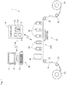
- Fig. 1 is a diagram conceptually illustrating the configuration of a printing apparatus 1 according to one preferred embodiment of the present invention.
- Fig. 2 is a bottom view of a head unit 30.
- Fig. 3 is a diagram conceptually illustrating the configuration of an ink supply system for the printing apparatus 1.
- This printing apparatus 1 is an inkjet printer which records a color image on the printing paper 9 that is an elongated strip-shaped recording medium by ejecting ink droplets from a plurality of ejection heads 32 onto the printing paper 9 while transporting the printing paper 9.
- the printing apparatus 1 includes a transport mechanism 20, five head units 30, a UV lamp 40, five ink supply parts 50, a pressure regulating part 60, a manipulation part 70 and a controller 10.
- the transport mechanism 20 is a mechanism for transporting the printing paper 9 in the transport direction that is the longitudinal direction of the printing paper 9 while holding the printing paper 9.
- the transport mechanism 20 according to the present preferred embodiment includes an unwinder 21, a plurality of transport rollers 22 and a winder 23.
- a motor serving as a power source is coupled to the unwinder 21, the plurality of transport rollers 22 and the winder 23.
- the unwinder 21, the plurality of transport rollers 22 and the winder 23 rotate when the controller 10 drives the motor.
- At least one or all of the transport rollers 22 may be follower rollers which are not coupled to the motor but rotate in accordance with the motion of the printing paper 9.
- the transport rollers 22 constitute a transport path for the printing paper 9.
- Each of the transport rollers 22 rotates about a horizontal axis to guide the printing paper 9 downstream along the transport path.
- the printing paper 9 comes in contact with the transport rollers 22, so that tension is applied to the printing paper 9. In this manner, the printing paper 9 is unwound from the unwinder 21, and is transported along the transport path formed by the transport rollers 22 to the winder 23. After being transported, the printing paper 9 is wound and collected on the winder 23.
- the five head units 30 are arranged in spaced apart relation in the transport direction over the transport path of the printing paper 9.
- the five head units 30 eject ink droplets of white (W), cyan (C), magenta (M), yellow (Y) and black (K), respectively, onto the upper surface of the printing paper 9.
- UV inks that are ultraviolet ray curable is used in the printing apparatus 1 according to the present preferred embodiment.
- the printing apparatus 1 is what is called a one-pass type recording apparatus which records a desired image pattern on the printing paper 9 by ejecting ink droplets from the head units 30 while the printing paper 9 passes under the head units 30 only once.
- the structure of only one of the head units 30 will be described below because the five head units 30 are substantially similar in structure to each other.
- the head unit 30 includes a housing 31, and the plurality of ejection heads 32 mounted to the housing 31.
- Each of the ejection heads 32 has an exposed ejection surface at the lower surface of the housing 31.
- the ejection surface that is the lower surface of each of the ejection heads 32 has a plurality of nozzles 33 disposed in a two-dimensional array. The positions of the individual nozzles 33 are shifted in the width direction, and each of the nozzles 33 is assigned to a region having a width of one pixel on the printing paper 9.
- the ejection heads 32 are arranged in a staggered configuration (in obliquely alternating positions) in the width direction.
- the ejection heads 32 include a first row 301 of ejection heads arranged in the width direction, and a second row 302 of ejection heads arranged in the width direction, the second row 302 being downstream of the first row 301.
- the ejection heads 32 in the first row 301 and the ejection heads 32 in the second row 302 are arranged alternately in the width direction.
- the ejection heads 32 are disposed at a high density in the width direction because of such an arrangement of the ejection heads 32 in a staggered configuration.
- each of the ejection heads 32 includes a casing 321, an ink reservoir chamber 322, a plurality of ink chambers 323, an ink supply port 324, an ink outlet port 325, and the plurality of nozzles 33.
- the ink reservoir chamber 322 and the ink chambers 323 are provided inside the casing 321.
- the ink reservoir chamber 322 is primarily filled with the ink supplied from the outside of each ejection head 32 through the ink supply port 324 thereinto.
- the ink supply port 324 and the ink outlet port 325 for providing communication between the ink reservoir chamber 322 and the outside are disposed over the ink reservoir chamber 322.
- the ink reservoir chamber 322 is in communication with the ink chambers 323 through respective communication ports 326. Thus, when the pressure in one of the ink chambers 323 is reduced, the ink is supplied from the ink reservoir chamber 322 into the ink chamber 323.
- the ink chambers 323 are filled with the ink secondarily in each ejection head 32. Although six ink chambers 323 are shown in Fig. 3 for purposes of convenience, a multiplicity of ink chambers 323 are provided for the respective nozzles 33 in actuality in each ejection head 32.
- the nozzles 33 are provided on the lower ends of the respective ink chambers 323.
- the nozzles 33 are small apertures for providing communication between the respective ink chambers 323 and an outside space. When no ink is ejected, a liquid surface of ink forms a meniscus inside each of the nozzles 33.
- Each of the nozzles 33 has a lower end portion which is exposed at the lower surface of the casing 321.
- a pressure generating element 327 is disposed on a wall surface of each of the ink chambers 323.
- the pressure generating element 327 is an in-head pressurizing mechanism for pressurizing the ink stored in each of the ink chambers 323.
- Each of the ejection heads 32 according to the present preferred embodiment is an ejection head of what is called a piezoelectric type.
- a piezoelectric element is used for the pressure generating element 327 according to the present preferred embodiment.
- the heads according to the present invention are not limited to those of a piezoelectric type.
- the heads according to the present invention may be what is called thermal ejection heads in which a heater used as the pressure generating element heats the liquid present in a pressure chamber to generate bubbles, thereby increasing the pressure in the pressure chamber.
- the UV lamp 40 irradiates the upper surface of the printing paper 9 transported by the transport mechanism 20 with ultraviolet light at a location downstream from the five head units 30.
- the ink droplets ejected onto the printing paper 9 are cured by the irradiation with the ultraviolet light.
- an image is fixed on the printing paper 9.
- This printing apparatus 1 includes the five ink supply parts 50 corresponding respectively to the five head units 30.
- the structure of only one of the ink supply parts 50 will be described below because the five ink supply parts 50 are substantially similar in structure to each other.
- the ink supply part 50 includes a main tank 51, a supply pump 52, a sub-tank 53, a return pump 54 and a pipe 55.
- the pipe 55 includes a first supply pipe 551, a second supply pipe 552, a plurality of third supply pipes 553, a plurality of first return pipes 554, and a second return pipe 555.
- the main tank 51 is an ink reservoir for storing ink therein.
- the volume of ink storable in the main tank 51 is greater than that of ink storable in the sub-tank 53.
- the first supply pipe 551 is a pipe which connects the main tank 51 and the sub-tank 53.
- the first supply pipe 551 has a first end connected for communication with the interior of the main tank 51 near a lower end portion of the main tank 51, and a second end connected for communication with the interior of the sub-tank 53.
- a first on-off valve 556, the supply pump 52 and a filter 557 are interposed in the first supply pipe 551.
- the first on-off valve 556 is disposed between the main tank 51 and the supply pump 52.
- the filter 557 is disposed between the supply pump 52 and the sub-tank 53.
- the supply pump 52 is a liquid feeding part for feeding the ink from the main tank 51 to the sub-tank 53.
- the supply pump 52 is interposed in the first supply pipe 551.
- the supply pump 52 generates a flow of ink directed from the main tank 51 toward the sub-tank 53 in the first supply pipe 551 in accordance with an operation signal from the controller 10.
- the ink stored in the main tank 51 is supplied through the first supply pipe 551 to the sub-tank 53.
- the first on-off valve 556 When the first on-off valve 556 is in a closed position, the communication through the first supply pipe 551 is closed off. That is, when the first on-off valve 556 is in the closed position, the communication between the main tank 51 and the sub-tank 53 is closed off. On the other hand, when the first on-off valve 556 is in an open position, the communication through the first supply pipe 551 is ensured.
- the first on-off valve 556 is normally in the closed position, and is brought into the open position only when the supply pump 52 is put into operation to supply the ink from the main tank 51 to the sub-tank 53. This prevents variations in the pressure in the sub-tank 53 from exerting influence on the main tank 51.
- the filter 557 removes solid components and foreign materials contained in the ink passing through the first supply pipe 551. This suppresses the contamination of solid components and foreign materials in the ink supplied to the sub-tank 53 and the ejection heads 32.
- the filter 557 may be disposed in a location other than between the supply pump 52 and the sub-tank 53 so long as the filter 557 is interposed in the first supply pipe 551.
- the sub-tank 53 is a tank which temporarily stores the ink therein.
- the sub-tank 53 supplies the ink stored therein to the ejection heads 32.
- the sub-tank 53 includes a liquid level sensor 531.
- the ink is stored in a lower portion of the sub-tank 53, and an upper portion of the sub-tank 53 is filled with clean air.
- the liquid level sensor 531 is a sensor for detecting the liquid level of the ink stored in the sub-tank 53.
- the controller 10 senses the liquid level of the ink in the sub-tank 53, based on a signal from the liquid level sensor 531, to judge whether to supply the ink to the sub-tank 53 or not.
- the controller 10 brings the first on-off valve 556 into the open position, and puts the supply pump 52 into operation.
- the controller 10 stops the supply pump 52, and brings the first on-off valve 556 into the closed position.
- the second supply pipe 552 and the third supply pipes 553 connect the sub-tank 53 and the respective ejection heads 32. That is, the sub-tank 53 is connected through the second supply pipe 552 and the third supply pipes 553 to the respective ejection heads 32.
- the second supply pipe 552 has a first end connected for communication with the interior of the sub-tank 53 near the lower end portion of the sub-tank 53, and a second end connected for communication with a first end of each of the third supply pipes 553.
- Each of the third supply pipes 553 has a second end connected to the ink supply port 324 of a corresponding one of the ejection heads 32.
- the sub-tank 53 is indirectly connected for communication with the ink reservoir chambers 322 and the ink chambers 323 of the ejection heads 32 through the second supply pipe 552 and the third supply pipes 553.
- the pressure in the ejection heads 32 is regulated by adjusting the pressure in the sub-tank 53.
- the first return pipes 554 and the second return pipe 555 connect the respective ejection heads 32 and the main tank 51.
- Each of the first return pipes 554 has a first end connected to the ink outlet port 325 of a corresponding one of the ejection heads 32, and a second end connected to a first end of the second return pipe 555.
- the second return pipe 555 has a second end connected for communication with the interior of the main tank 51.
- a second on-off valve 558 is interposed in each of the first return pipes 554.
- the communication through a corresponding one of the first return pipes 554 in which the second on-off valve 558 is interposed is closed off. That is, when the second on-off valve 558 is in the closed position, the communication between the ink reservoir chamber 322 of a corresponding one of the ejection heads 32 and the second return pipe 555 is closed off.
- the second on-off valve 558 is in an open position, the communication through a corresponding one of the first return pipes 554 in which the second on-off valve 558 is interposed is ensured. That is, when the second on-off valve 558 is in the open position, the communication between the ink reservoir chamber 322 of a corresponding one of the ejection heads 32 and the second return pipe 555 is ensured.
- the return pump 54 and a third on-off valve 559 are interposed in the second return pipe 555.
- the third on-off valve 559 is disposed between the return pump 54 and the main tank 51.
- the return pump 54 is a liquid feeding part for feeding the ink from the ink reservoir chambers 322 of the respective ejection heads 32 to the main tank 51.
- the return pump 54 is interposed in the second return pipe 555.
- the return pump 54 generates a flow of ink directed from the first return pipes 554 toward the main tank 51 in the second return pipe 555 in accordance with an operation signal from the controller 10.
- the ink stored in the ink reservoir chambers 322 of the respective ejection heads 32 is returned to flow through the first return pipes 554 and the second return pipe 555 back to the main tank 51.
- the third on-off valve 559 When the third on-off valve 559 is in a closed position, the communication through the second return pipe 555 is closed off. That is, when the third on-off valve 559 is in the closed position, the communication between the first return pipes 554 and the main tank 51 is closed off. On the other hand, when the third on-off valve 559 is in an open position, the communication through the second return pipe 555 is ensured.
- the third on-off valve 559 is normally in the closed position, and is brought into the open position only when the return pump 54 is put into operation to return the ink from the ejection heads 32 back to the main tank 51.
- the provision of the second on-off valve 558 in each of the first return pipes 554 allows the individual ejection heads 32 to return the ink.
- the second on-off valves 558 corresponding to the predetermined ones of the ejection heads 32 and the third on-off valve 559 are brought into the open position whereas the remainder of the second on-off valves 558 are in the closed position, and the return pump 54 is put into operation.
- the main tank 51, the supply pump 52, the return pump 54, the first supply pipe 551, the first return pipes 554, the second return pipe 555, the first on-off valve 556, the second on-off valves 558 and the third on-off valve 559 constitute an ink return part 500 for feeding the ink from the ejection heads 32 to the sub-tank 53 in this manner.
- the pressure regulating part 60 controls the pressure in the sub-tank 53 and in the ejection heads 32.
- the pressure regulating part 60 includes a first main pipe 61, a buffer tank 62, a second main pipe 63, an open-to-atmosphere part 64, an exhaust part 65 and a pressure sensor 66.
- the open-to-atmosphere part 64 includes an open-to-atmosphere pipe 641 and an open-to-atmosphere control valve 642.
- the exhaust part 65 includes an exhaust pipe 651, an exhaust pump 652 and an exhaust control valve 653.
- the first main pipe 61 has a first end connected for communication with the interior of the sub-tank 53 at the top of the sub-tank 53.
- the liquid level of the ink in the sub-tank 53 is near the liquid level sensor 531.
- the first end of the first main pipe 61 does not contact the ink in the sub-tank 53 but is disposed in a gas present in the upper portion of the sub-tank 53.
- the first main pipe 61 has a second end connected for communication with the interior of the buffer tank 62.
- the buffer tank 62 is an enclosed tank filled with a gas.
- the pressure sensor 66 measures the pressure in the buffer tank 62.
- the interior of the sub-tank 53 and the interior of the buffer tank 62 are in communication with each other through the first main pipe 61, so that the pressure in the sub-tank 53 is approximately equal to the pressure in the buffer tank 62. For this reason, the pressure sensor 66 indirectly measures the pressure in the sub-tank 53.
- the open-to-atmosphere part 64 and the exhaust part 65 may be connected to the sub-tank 53 without the buffer tank 62 connected therebetween.
- the pressure sensor 66 may measure the pressure in the sub-tank 53 at the upper part of the sub-tank 53.
- the pressure sensor 66 directly measures the pressure in the sub-tank 53 in this manner, noise is prone to occur in the values measured with the pressure sensor 66 due to the pulsation of the supply pump 52 while the supply pump 52 is in operation.
- the buffer tank 62 is provided and the pressure sensor 66 measures the pressure in the buffer tank 62 as in the present preferred embodiment, the noise due to the pulsation of the supply pump 52 is reduced.
- the second main pipe 63 has a first end connected for communication with the interior of the buffer tank 62, and a second end connected to a first end of the open-to-atmosphere pipe 641 and a first end of the exhaust pipe 651. That is, the open-to-atmosphere part 64 and the exhaust part 65 are connected to the second end of the second main pipe 63.
- the buffer tank 62 is connected to the open-to-atmosphere part 64 and the exhaust part 65.
- the first end of the open-to-atmosphere pipe 641 is connected for communication with the second end of the second main pipe 63.
- the open-to-atmosphere pipe 641 has a second end open to the atmosphere.
- the open-to-atmosphere control valve 642 is interposed in the open-to-atmosphere pipe 641.
- the open-to-atmosphere control valve 642 performs the switching of the sub-tank 53 and the outside between a communicating state and a closed-off state.
- the open-to-atmosphere control valve 642 is in an open position, the second main pipe 63 is open to the atmosphere.
- the open-to-atmosphere control valve 642 when the open-to-atmosphere control valve 642 is in the open position, the sub-tank 53 and the buffer tank 62 are in communication with the outside and are thus open to the atmosphere. When the open-to-atmosphere control valve 642 is in a closed position, the communication between the second main pipe 63 and the outside is closed off.
- the controller 10 brings the open-to-atmosphere control valve 642 into the open position in order to reduce the pressure in the sub-tank 53 when the pressure in the sub-tank 53 is higher than atmospheric pressure. This reduces the pressure in the sub-tank 53 and in the buffer tank 62 quickly to atmospheric pressure.
- the controller 10 holds the open-to-atmosphere control valve 642 in the open position for a fixed time period in order to increase the pressure in the sub-tank 53 when a desired pressure is a negative pressure lower than atmospheric pressure and the pressure in the sub-tank 53 is lower than the desired pressure. This causes the pressure in the sub-tank 53 and in the buffer tank 62 to approach atmospheric pressure and to increase.
- the first end of the exhaust pipe 651 is connected for communication with the second end of the second main pipe 63.
- the exhaust pipe 651 has a second end connected to the exhaust pump 652.
- the exhaust pump 652 is a gas flow producing part for exhausting the gas from the exhaust pipe 651.
- the exhaust control valve 653 is interposed in the exhaust pipe 651. When the exhaust control valve 653 is in an open position, the second main pipe 63 and the exhaust pump 652 are in communication with each other. On the other hand, when the exhaust control valve 653 is in a closed position, the communication between the second main pipe 63 and the exhaust pump 652 is closed off.
- the exhaust pump 652 when the exhaust pump 652 is driven while the exhaust control valve 653 is in the open position, the gas in the sub-tank 53 and in the buffer tank 62 is exhausted through the exhaust pipe 651.
- the pressure in the ink chambers 323 is adjusted to a pressure (referred to hereinafter as a meniscus pressure) at which a meniscus of ink is formed in each nozzle 33.
- a meniscus pressure a pressure at which a meniscus of ink is formed in each nozzle 33.
- the pressure in the sub-tank 53 is set so that the pressure in the ink reservoir chambers 322 is a negative pressure because the ink chambers 323 are disposed under the ink reservoir chamber 322.
- the controller 10 brings the exhaust control valve 653 into the open position and drives the exhaust pump 652 to reduce the pressure in the sub-tank 53 to the meniscus pressure.
- ink droplets are ejected from the ejection heads 32 of each of the head units 30 onto the upper surface of the printing paper 9 while the printing paper 9 is transported by the transport mechanism 20.
- the nozzles 33 ejecting the ink droplets in the positions opposed to substantially the full width of the upper surface of the printing paper 9 are disposed in each of the head units 30. This allows each of the head units 30 to eject the ink droplets across substantially the full width of the upper surface of the printing paper 9.
- the five head units 30 corresponding to the respective colors sequentially perform such a process of ejecting the ink droplets to form a multi-color pattern on the upper surface of the printing paper 9.
- the manipulation part 70 includes a display part 71 and an input part 72. Information about the operating status and the like of the printing apparatus 1 which is inputted from the controller 10 is displayed on the display part 71. An operator may input commands from the input part 72 to the controller 10.
- a liquid crystal display for example, is used for the display part 71.
- a keyboard and a mouse for example, are used for the input part 72.
- the display part 71 includes a loudspeaker 73.
- the loudspeaker 73 constitutes a notifying part which uses voice or sound to provide notification of an error to an operator in accordance with an instruction from the controller 10.
- the display part 71 may constitute a notifying part which displays a character or an image thereon to provide notification of an error to an operator.
- the display part 71 and the input part 72 in the manipulation part 70 are separate devices independent of the printing apparatus 1.
- the manipulation part 70 of a touch panel type in which the display part 71 and the input part 72 are integrated together may be mounted to the body of the printing apparatus 1.
- the controller 10 is a section for controlling the operations of the parts of the printing apparatus 1.
- the controller 10 according to the present preferred embodiment is formed by a computer including an arithmetic processor 11 such as a CPU, a memory 12 such as a RAM, and a storage part 13 such as a hard disk drive.
- an arithmetic processor 11 such as a CPU
- a memory 12 such as a RAM
- a storage part 13 such as a hard disk drive.
- the controller 10 is electrically connected to the transport mechanism 20, the pressure generating elements 327 of the five head units 30, the UV lamp 40, the supply pump 52, the liquid level sensor 531, the return pump 54, the first on-off valve 556, the second on-off valves 558, the third on-off valve 559, the open-to-atmosphere control valve 642, the exhaust pump 652, the exhaust control valve 653, the pressure sensor 66, the display part 71 and the input part 72.
- the controller 10 temporarily reads a computer program 131 and data 132 which are stored in the storage part 13 onto the memory 12.
- the arithmetic processor 11 performs arithmetic processing based on the computer program 131 and the data 132, so that the controller 10 controls the operations of the parts of the printing apparatus 1.
- the controller 10 may be formed by electronic circuitry.
- the controller 10 includes an operation sensing part 101 and an error detection part 102 which are processing parts implemented in the form of software. Specifically, the operation sensing part 101 and the error detection part 102 are implemented by the arithmetic processor 11, the memory 12 and the storage part 13 described above.
- the operation sensing part 101 senses the number of times or frequency of a negative pressure reduction operation performed by the pressure regulating part 60.
- the error detection part 102 judges whether the ink return part 500 is operating normally or not, based on a sensing signal from the operation sensing part 101.
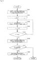
- Fig. 5 is a flow diagram showing a procedure for the ink circulating process according to the present preferred embodiment.
- the UV inks that are ultraviolet ray curable are used in the printing apparatus 1.
- White (W) UV ink contains titanium oxide which is a precipitable ingredient.
- the white (W) UV ink is more prone to precipitation and agglomeration inside the ejection heads 32 and inside pipe lines through which the ink passes than other types of inks.
- the printing apparatus 1 performs the ink circulating process on at least the head unit 30 and the ink supply part 50 for white (W) at regular time intervals during a time period over which no printing process is performed. For example, the ink circulating process for three minutes at one time is performed at time intervals of five minutes.
- time period over which no printing process is performed includes not only a time period over which all of the head units 30 perform no printing process but also a time period over which the head unit 30 of interest is not used for the printing process. That is, the ink circulating process is performed on the head unit 30 and the ink supply part 50 for white (W) when the head unit 30 for white (W) is not used although the printing process is performed using other four colors.
- the controller 10 initially starts counting the number of times of the negative pressure reduction operation (Step S101), as shown in Fig. 5 . Specifically, the operation sensing part 101 of the controller 10 starts sensing the number of times that the pressure regulating part 60 performs the negative pressure reduction operation. Then, the controller 10 sets a head number n to 1 (Step S102). In this printing apparatus 1, the number of heads N is 6 because one head unit 30 includes six ejection heads.
- the controller 10 returns the ink from the n-th ejection head 32 back to the main tank 51 (Step S103). Specifically, the controller 10 puts the return pump 54 into operation while holding the second on-off valve 558 corresponding to the n-th ejection head 32 and the third on-off valve 559 in the open position. After a lapse of a predetermined time period, the controller 10 stops the return pump 54, and brings the second on-off valve 558 and the third on-off valve 559 held in the open position into the closed position. In the present preferred embodiment, the controller 10 performs such a return operation several times.
- a circulating operation causes the ink to be ejected from the ejection heads 32.
- the pressure in the ejection heads 32, in the sub-tank 53 and in the buffer tank 62 is reduced when the ink is being circulated normally.
- the controller 10 causes the pressure regulating part 60 to perform a meniscus control process.
- the pressure in the ejection heads 32 is controlled to be equal to the meniscus pressure.
- the pressure regulating part 60 performs the negative pressure reduction operation and a positive pressure reduction operation, so that the pressure in the ejection heads 32 is controlled to fall within a fixed range.
- Fig. 6 is a flow diagram showing a procedure for the meniscus control process according to the present preferred embodiment.
- a judgment is made as to whether the pressure value measured with the pressure sensor 66 is less than a predetermined lower limit or not (Step S201), as shown in Fig. 6 .
- Step S202 Upon judging that the pressure value measured with the pressure sensor 66 is less than the predetermined lower limit in Step S201, the controller 10 causes the pressure regulating part 60 to perform the negative pressure reduction operation (Step S202). Specifically, the controller 10 brings the open-to-atmosphere control valve 642 into the open position, and then brings the open-to-atmosphere control valve 642 into the closed position after a lapse of a predetermined time period. This causes the sub-tank 53 and the buffer tank 62 to be open to the atmosphere for the predetermined time period, thereby increasing the pressure in the ejection heads 32, in the sub-tank 53 and in the buffer tank 62. After the completion of the Step S202, the procedure returns to Step S201.
- Step S203 a judgment is made as to whether the pressure value measured with the pressure sensor 66 is greater than a predetermined upper limit or not (Step S203).
- Step S204 Upon judging that the pressure value measured with the pressure sensor 66 is greater than the predetermined upper limit in Step S203, the controller 10 causes the pressure regulating part 60 to perform the positive pressure reduction operation (Step S204). Specifically, the controller 10 brings the exhaust control valve 653 into the open position, and puts the exhaust pump 652 into operation. After a lapse of a predetermined time period, the controller 10 stops the exhaust pump 652, and brings the exhaust control valve 653 into the closed position. This causes the gas in the sub-tank 53 and in the buffer tank 62 to be exhausted therefrom, thereby reducing the pressure in the ejection heads 32, in the sub-tank 53 and in the buffer tank 62. After the completion of the Step S204, the procedure returns to Step S201.
- Step S103 reduces the pressure in the ejection heads 32, in the sub-tank 53 and in the buffer tank 62 when the ink is being circulated normally.
- the controller 10 should perform the negative pressure reduction operation in association with the return operation in Step S103.
- the controller 10 is hence capable of judging whether the ink is being circulated normally or not by sensing the number of times of the negative pressure reduction operation between Steps S101 and S106.
- Step S104 the controller 10 increments the head number n (Step S104). Thereafter, the controller 10 judges whether the head number n is greater than the number of heads N or not (Step S105).
- Step S105 When the controller 10 judges that the head number n is not greater than the number of heads N in Step S105, the procedure returns to Step S103, and the controller 10 performs the return operation on the next ejection head 32. On the other hand, when the controller 10 judges that the head number n is greater than the number of heads N in Step S105, the controller 10 considers that the return operation of all of the ejection heads 32 is completed to stop counting the number of times of the negative pressure reduction operation by means of the operation sensing part 101 (Step S106).
- the error detection part 102 of the controller 10 judges whether the number of times of the negative pressure reduction operation between Steps S101 and S106 is included within a predetermined range or not (Step S107). In other words, the error detection part 102 judges whether the ink return part 500 is operating normally or not, based on the sensing signal from the operation sensing part 101 while the return pump 54 is in operation.
- Step S108 When the error detection part 102 judges that the number of times of the negative pressure reduction operation is included within the predetermined range in Step S107, the procedure proceeds to Step S108. That is, when the number of times of the negative pressure reduction operation coincides with a predetermined condition, the error detection part 102 judges that the ink return part 500 is operating normally. In this case, the controller 10 judges that the ink is being circulated normally to continue the ink circulating process. Then, the controller 10 performs the operation of supplying the ink to the sub-tank 53 (Step S108).
- Step S108 the controller 10 initially judges whether the supply of the ink to the sub-tank 53 is necessary or not, based on a sensing signal from the liquid level sensor 531. Upon judging that the supply of the ink to the sub-tank 53 is necessary, the controller 10 brings the first on-off valve 556 into the open position, and puts the supply pump 52 into operation. Then, upon judging that the liquid level of the ink in the sub-tank 53 reaches a predetermined upper limit, based on the sensing signal from the liquid level sensor 531, the controller 10 stops the supply pump 52, and brings the first on-off valve 556 into the closed position. Thereafter, the controller 10 completes the ink circulating process. Upon judging that the supply of the ink to the sub-tank 53 is not necessary in Step S108, the controller 10 completes the ink circulating process normally.
- the controller 10 judges that the ink is not normally being circulated. That is, when the number of times of the negative pressure reduction operation does not coincide with the predetermined condition, the error detection part 102 judges that the ink return part 500 is not normally operating. Upon sensing an error in this manner, the controller 10 causes the notifying part to make an error notification. In the present preferred embodiment, the controller 10 uses voice or sound from the loudspeaker 73 provided in the display part 71 to provide notification of an error to an operator.
- the ink is returned from the ejection heads 32 through the main tank 51 back to the sub-tank 53 in the ink circulating process in this printing apparatus 1. While such ink return is performed, the pressure sensor 66 measures the pressure in the sub-tank 53 through the buffer tank 62, and the negative pressure reduction operation is performed when the pressure is not greater than the predetermined value. Then, the controller 10 senses the number of times of the negative pressure reduction operation during the circulating process to judge whether the ink return part 500 is operating normally or not, based on the sensed number of times. That is, while the ink circulating process is performed, the controller 10 senses the number of times or frequency of the negative pressure reduction operation performed by the pressure regulating part 60 as part of the meniscus control to thereby judge whether the ink is being circulated normally or not.
- Fig. 7 is a flow diagram showing a procedure for the ink circulating process according to one modification of the present invention.
- the controller 10 initially sets the head number n to 1 (Step S301). Then, the operation sensing part 101 of the controller 10 starts counting the number of times of the negative pressure reduction operation (Step S302). Next, the controller 10 returns the ink from the n-th ejection head 32 back to the main tank 51 (Step S303). Then, the controller 10 stops counting the number of times of the negative pressure reduction operation by means of the operation sensing part 101 (Step S304).
- Step S305 the error detection part 102 of the controller 10 judges whether the number of times of the negative pressure reduction operation between Steps S302 and S305 is included within a predetermined range or not (Step S305).
- the procedure proceeds to Step S306.
- the error detection part 102 judges that the number of times of the negative pressure reduction operation is not included within the predetermined range in Step S305, an error notification is made.
- the controller 10 increments the head number n in Step S306. Subsequently, the controller 10 judges whether the head number n is greater than the number of heads N or not (Step S307). When the controller 10 judges that the head number n is not greater than the number of heads N in Step S307, the procedure returns to Step S302, and the controller 10 performs the return operation on the next ejection head 32. On the other hand, when the controller 10 judges that the head number n is greater than the number of heads N in Step S307, the procedure proceeds to Step S308, and the controller 10 performs the operation of supplying the ink to the sub-tank 53.
- the judgement may be made as to whether the number of times of the negative pressure reduction operation in the ink circulating process is included within the predetermined range or not, as in the modification of Fig. 7 .
- Fig. 8 is a flow diagram showing a procedure for the ink circulating process according to another modification of the present invention.
- the operation sensing part 101 of the controller 10 initially starts counting the number of times of the negative pressure reduction operation (Step S401). Then, the controller 10 sets the head number n to 1 (Step S402). Next, the controller 10 returns the ink from the n-th ejection head 32 back to the main tank 51 (Step S403). Subsequently, the controller 10 performs the operation of supplying the ink to the sub-tank 53 (Step S404). Thereafter, the controller 10 increments the head number n (Step S405).
- Step S406 the controller 10 judges whether the head number n is greater than the number of heads N or not (Step S406).
- the procedure returns to Step S403, and the controller 10 performs the return operation on the next ejection head 32.
- the controller 10 judges that the head number n is greater than the number of heads N in Step S406, the procedure proceeds to Step S407, and the controller 10 stops counting the number of times of the negative pressure reduction operation by means of the operation sensing part 101.
- Step S408 the error detection part 102 of the controller 10 judges whether the number of times of the negative pressure reduction operation between Steps S401 and S407 is included within a predetermined range or not.
- the controller 10 completes the ink circulating process normally.
- an error notification is made.
- the operation of supplying the ink to the sub-tank 53 may be performed, as in the modification of Fig. 8 .
- the operation of supplying the ink to the sub-tank 53 is performed at the time of completion of the return operation for one or a predetermined number of ejection heads 32.
- the printing apparatus 1 includes the five head units 30, the number of head units 30 in the printing apparatus 1 may be in the range of one to four or not less than six.
- the UV inks that are ultraviolet ray curable are used in the printing apparatus 1 according to the aforementioned preferred embodiment, the present invention is not limited to this.
- other types of inks such as oil-based ink and water-based ink dried by hot gases may be used in place of the UV ink.
- the printing apparatus 1 need not include a UV lamp.
- the printing apparatus 1 prints an image on the printing paper 9 serving as a recording medium.
- the printing apparatus 1 according to the present invention may be configured to print a pattern of an image and the like on a sheet-like recording medium other than general paper (for example, a film made of resin and the like).
Landscapes
- Ink Jet (AREA)
Abstract
Description
- The present invention relates to an inkjet printer and a method of checking a liquid feeding state in an inkjet printer.
- A printing apparatus having an ejection head for ejecting ink toward a recording medium has heretofore been used. A conventional printing apparatus is disclosed, for example, in Japanese Patent Application Laid-Open No.
2001-138544 - If ink is not ejected from the ejection head for a long period of time, there are cases in which the precipitation or/and agglomeration of ink components occur inside the ejection head or inside a pipe line through which the ink passes. If such precipitation or/and agglomeration of the ink components occur, there is apprehension about ejection failures of the ink from the ejection head. It is hence desirable to prevent the precipitation or/and agglomeration of the ink components in this type of printing apparatus by circulating the ink during a time period over which no printing process is performed.
- If the precipitation or/and agglomeration of the ink components have already occurred inside the ejection head or inside the pipe line through which the ink passes, there are cases in which the ink cannot be circulated normally in the ink circulating process. It is hence necessary to check whether the ink is being circulated normally or not in the ink circulating process.
- The printing apparatus disclosed in Japanese Patent Application Laid-Open No.
2001-138544 - In view of the foregoing, it is an object of the present invention to provide a technique capable of checking whether ink is being circulated normally or not without the provision of a sensor in an ink circulation path.
- To solve the aforementioned problems, a first aspect of the present invention is intended for an inkjet printer comprising: at least one head including a plurality of nozzles for ejecting ink toward a recording medium; a tank for storing the ink therein and supplying the ink to the head; an ink return part for feeding the ink from the head to the tank; a pressure regulating part for performing a negative pressure reduction operation which increases the pressure in the tank when the pressure in the tank is not greater than a predetermined value; an operation sensing part for sensing the number of times or frequency of the negative pressure reduction operation performed by the pressure regulating part; and an error detection part for judging whether the ink return part is operating normally or not, based on a sensing signal from the operation sensing part.
- A second aspect of the present invention is intended for a method of checking a liquid feeding state in an inkjet printer, the inkjet printer including a head including a plurality of nozzles for ejecting ink toward a recording medium, a tank for supplying the ink to the head, and an ink return part for feeding the ink from the head to the tank, the method checking the feeding state of the ink from the head to the tank. The method comprises the steps of: a) measuring the pressure in the tank, while returning the ink from the head back to the tank, to judge whether the pressure in the tank is greater than a predetermined value or not; b) performing a negative pressure reduction operation which increases the pressure in the tank when the pressure in the tank is not greater than the predetermined value during the execution of the step a); and c) sensing the number of times or frequency of the negative pressure reduction operation during the execution of the step a) to judge whether the ink return part is operating normally or not, based on the number of times or the frequency which is sensed.
- According to the first and second aspects of the present invention, whether the ink is being circulated normally or not is checked without the provision of a sensor in an ink circulation path.
- These and other objects, features, aspects and advantages of the present invention will become more apparent from the following detailed description of the present invention when taken in conjunction with the accompanying drawings.
-
-
Fig. 1 is a diagram conceptually illustrating the configuration of a printing apparatus according to one preferred embodiment of the present invention; -
Fig. 2 is a bottom view of a head unit according to the one preferred embodiment of the present invention; -
Fig. 3 is a diagram conceptually illustrating the configuration of an ink supply system for the printing apparatus according to the one preferred embodiment of the present invention; -
Fig. 4 is a block diagram showing a control system for the printing apparatus according to the one preferred embodiment of the present invention; -
Fig. 5 is a flow diagram showing a procedure for an ink circulating process according to the one preferred embodiment of the present invention; -
Fig. 6 is a flow diagram showing a procedure for a meniscus control process according to the one preferred embodiment of the present invention; and -
Figs. 7 and8 are flow diagrams showing procedures for the ink circulating process according to modifications of the present invention. - A preferred embodiment according to the present invention will now be described with reference to the drawings. A direction in which
printing paper 9 is transported is referred to as a "transport direction", and a horizontal direction orthogonal to the transport direction is referred to as a "width direction" hereinafter. -
Fig. 1 is a diagram conceptually illustrating the configuration of aprinting apparatus 1 according to one preferred embodiment of the present invention.Fig. 2 is a bottom view of ahead unit 30.Fig. 3 is a diagram conceptually illustrating the configuration of an ink supply system for theprinting apparatus 1. - This
printing apparatus 1 is an inkjet printer which records a color image on theprinting paper 9 that is an elongated strip-shaped recording medium by ejecting ink droplets from a plurality ofejection heads 32 onto theprinting paper 9 while transporting theprinting paper 9. As shown inFigs. 1 to 3 , theprinting apparatus 1 includes atransport mechanism 20, fivehead units 30, aUV lamp 40, fiveink supply parts 50, apressure regulating part 60, amanipulation part 70 and acontroller 10. - The
transport mechanism 20 is a mechanism for transporting theprinting paper 9 in the transport direction that is the longitudinal direction of theprinting paper 9 while holding theprinting paper 9. Thetransport mechanism 20 according to the present preferred embodiment includes anunwinder 21, a plurality oftransport rollers 22 and awinder 23. - A motor (not shown) serving as a power source is coupled to the
unwinder 21, the plurality oftransport rollers 22 and the winder 23. Theunwinder 21, the plurality oftransport rollers 22 and the winder 23 rotate when thecontroller 10 drives the motor. At least one or all of thetransport rollers 22 may be follower rollers which are not coupled to the motor but rotate in accordance with the motion of theprinting paper 9. - The
transport rollers 22 constitute a transport path for theprinting paper 9. Each of thetransport rollers 22 rotates about a horizontal axis to guide theprinting paper 9 downstream along the transport path. Theprinting paper 9 comes in contact with thetransport rollers 22, so that tension is applied to theprinting paper 9. In this manner, theprinting paper 9 is unwound from theunwinder 21, and is transported along the transport path formed by thetransport rollers 22 to the winder 23. After being transported, theprinting paper 9 is wound and collected on thewinder 23. - The five
head units 30 are arranged in spaced apart relation in the transport direction over the transport path of theprinting paper 9. The fivehead units 30 eject ink droplets of white (W), cyan (C), magenta (M), yellow (Y) and black (K), respectively, onto the upper surface of theprinting paper 9. UV inks that are ultraviolet ray curable is used in theprinting apparatus 1 according to the present preferred embodiment. - The
printing apparatus 1 according to the present preferred embodiment is what is called a one-pass type recording apparatus which records a desired image pattern on theprinting paper 9 by ejecting ink droplets from thehead units 30 while theprinting paper 9 passes under thehead units 30 only once. The structure of only one of thehead units 30 will be described below because the fivehead units 30 are substantially similar in structure to each other. - As shown in
Fig. 2 , thehead unit 30 includes ahousing 31, and the plurality ofejection heads 32 mounted to thehousing 31. Each of theejection heads 32 has an exposed ejection surface at the lower surface of thehousing 31. The ejection surface that is the lower surface of each of theejection heads 32 has a plurality ofnozzles 33 disposed in a two-dimensional array. The positions of theindividual nozzles 33 are shifted in the width direction, and each of thenozzles 33 is assigned to a region having a width of one pixel on theprinting paper 9. - As shown in
Fig. 2 , theejection heads 32 are arranged in a staggered configuration (in obliquely alternating positions) in the width direction. Specifically, theejection heads 32 include afirst row 301 of ejection heads arranged in the width direction, and asecond row 302 of ejection heads arranged in the width direction, thesecond row 302 being downstream of thefirst row 301. Theejection heads 32 in thefirst row 301 and theejection heads 32 in thesecond row 302 are arranged alternately in the width direction. Theejection heads 32 are disposed at a high density in the width direction because of such an arrangement of theejection heads 32 in a staggered configuration. - As shown in
Fig. 3 , each of theejection heads 32 includes acasing 321, anink reservoir chamber 322, a plurality ofink chambers 323, anink supply port 324, anink outlet port 325, and the plurality ofnozzles 33. Theink reservoir chamber 322 and theink chambers 323 are provided inside thecasing 321. - The
ink reservoir chamber 322 is primarily filled with the ink supplied from the outside of eachejection head 32 through theink supply port 324 thereinto. Theink supply port 324 and theink outlet port 325 for providing communication between theink reservoir chamber 322 and the outside are disposed over theink reservoir chamber 322. Theink reservoir chamber 322 is in communication with theink chambers 323 throughrespective communication ports 326. Thus, when the pressure in one of theink chambers 323 is reduced, the ink is supplied from theink reservoir chamber 322 into theink chamber 323. - The
ink chambers 323 are filled with the ink secondarily in eachejection head 32. Although sixink chambers 323 are shown inFig. 3 for purposes of convenience, a multiplicity ofink chambers 323 are provided for therespective nozzles 33 in actuality in eachejection head 32. - The
nozzles 33 are provided on the lower ends of therespective ink chambers 323. Thenozzles 33 are small apertures for providing communication between therespective ink chambers 323 and an outside space. When no ink is ejected, a liquid surface of ink forms a meniscus inside each of thenozzles 33. Each of thenozzles 33 has a lower end portion which is exposed at the lower surface of thecasing 321. - A
pressure generating element 327 is disposed on a wall surface of each of theink chambers 323. Thepressure generating element 327 is an in-head pressurizing mechanism for pressurizing the ink stored in each of theink chambers 323. - Each of the ejection heads 32 according to the present preferred embodiment is an ejection head of what is called a piezoelectric type. Thus, a piezoelectric element is used for the
pressure generating element 327 according to the present preferred embodiment. When an ejection signal that is an electric signal is sent from thecontroller 10 to thepressure generating element 327, thepressure generating element 327 is deformed to exert pressure on the ink which fills each of theink chambers 323. When the pressure in each of theink chambers 323 is increased, the ink in each of theink chambers 323 is ejected in the form of droplets from each of thenozzles 33. - The heads according to the present invention are not limited to those of a piezoelectric type. For example, the heads according to the present invention may be what is called thermal ejection heads in which a heater used as the pressure generating element heats the liquid present in a pressure chamber to generate bubbles, thereby increasing the pressure in the pressure chamber.
- The
UV lamp 40 irradiates the upper surface of theprinting paper 9 transported by thetransport mechanism 20 with ultraviolet light at a location downstream from the fivehead units 30. The ink droplets ejected onto theprinting paper 9 are cured by the irradiation with the ultraviolet light. Thus, an image is fixed on theprinting paper 9. - This
printing apparatus 1 includes the fiveink supply parts 50 corresponding respectively to the fivehead units 30. The structure of only one of theink supply parts 50 will be described below because the fiveink supply parts 50 are substantially similar in structure to each other. - As shown in
Fig. 3 , theink supply part 50 includes amain tank 51, asupply pump 52, a sub-tank 53, areturn pump 54 and apipe 55. Thepipe 55 includes afirst supply pipe 551, asecond supply pipe 552, a plurality ofthird supply pipes 553, a plurality offirst return pipes 554, and asecond return pipe 555. - The
main tank 51 is an ink reservoir for storing ink therein. The volume of ink storable in themain tank 51 is greater than that of ink storable in the sub-tank 53. - The
first supply pipe 551 is a pipe which connects themain tank 51 and the sub-tank 53. Thefirst supply pipe 551 has a first end connected for communication with the interior of themain tank 51 near a lower end portion of themain tank 51, and a second end connected for communication with the interior of the sub-tank 53. - A first on-off
valve 556, thesupply pump 52 and afilter 557 are interposed in thefirst supply pipe 551. The first on-offvalve 556 is disposed between themain tank 51 and thesupply pump 52. Thefilter 557 is disposed between thesupply pump 52 and the sub-tank 53. - The
supply pump 52 is a liquid feeding part for feeding the ink from themain tank 51 to the sub-tank 53. Thesupply pump 52 is interposed in thefirst supply pipe 551. Thesupply pump 52 generates a flow of ink directed from themain tank 51 toward the sub-tank 53 in thefirst supply pipe 551 in accordance with an operation signal from thecontroller 10. Thus, the ink stored in themain tank 51 is supplied through thefirst supply pipe 551 to the sub-tank 53. - When the first on-off
valve 556 is in a closed position, the communication through thefirst supply pipe 551 is closed off. That is, when the first on-offvalve 556 is in the closed position, the communication between themain tank 51 and the sub-tank 53 is closed off. On the other hand, when the first on-offvalve 556 is in an open position, the communication through thefirst supply pipe 551 is ensured. The first on-offvalve 556 is normally in the closed position, and is brought into the open position only when thesupply pump 52 is put into operation to supply the ink from themain tank 51 to the sub-tank 53. This prevents variations in the pressure in the sub-tank 53 from exerting influence on themain tank 51. - The
filter 557 removes solid components and foreign materials contained in the ink passing through thefirst supply pipe 551. This suppresses the contamination of solid components and foreign materials in the ink supplied to the sub-tank 53 and the ejection heads 32. Thefilter 557 may be disposed in a location other than between thesupply pump 52 and the sub-tank 53 so long as thefilter 557 is interposed in thefirst supply pipe 551. - The sub-tank 53 is a tank which temporarily stores the ink therein. The sub-tank 53 supplies the ink stored therein to the ejection heads 32. The sub-tank 53 includes a
liquid level sensor 531. The ink is stored in a lower portion of the sub-tank 53, and an upper portion of the sub-tank 53 is filled with clean air. - The
liquid level sensor 531 is a sensor for detecting the liquid level of the ink stored in the sub-tank 53. Thecontroller 10 senses the liquid level of the ink in the sub-tank 53, based on a signal from theliquid level sensor 531, to judge whether to supply the ink to the sub-tank 53 or not. For the supply of the ink from themain tank 51 to the sub-tank 53, thecontroller 10 brings the first on-offvalve 556 into the open position, and puts thesupply pump 52 into operation. For the stop of the ink supply from themain tank 51 to the sub-tank 53, thecontroller 10 stops thesupply pump 52, and brings the first on-offvalve 556 into the closed position. - The
second supply pipe 552 and thethird supply pipes 553 connect the sub-tank 53 and the respective ejection heads 32. That is, the sub-tank 53 is connected through thesecond supply pipe 552 and thethird supply pipes 553 to the respective ejection heads 32. - The
second supply pipe 552 has a first end connected for communication with the interior of the sub-tank 53 near the lower end portion of the sub-tank 53, and a second end connected for communication with a first end of each of thethird supply pipes 553. Each of thethird supply pipes 553 has a second end connected to theink supply port 324 of a corresponding one of the ejection heads 32. Thus, the ink stored in the sub-tank 53 is supplied through thesecond supply pipe 552, thethird supply pipes 553 and theink supply ports 324 to theink reservoir chambers 322 of the respective ejection heads 32. - In this manner, the sub-tank 53 is indirectly connected for communication with the
ink reservoir chambers 322 and theink chambers 323 of the ejection heads 32 through thesecond supply pipe 552 and thethird supply pipes 553. Thus, the pressure in the ejection heads 32 is regulated by adjusting the pressure in the sub-tank 53. - The
first return pipes 554 and thesecond return pipe 555 connect the respective ejection heads 32 and themain tank 51. Each of thefirst return pipes 554 has a first end connected to theink outlet port 325 of a corresponding one of the ejection heads 32, and a second end connected to a first end of thesecond return pipe 555. Thesecond return pipe 555 has a second end connected for communication with the interior of themain tank 51. - A second on-off
valve 558 is interposed in each of thefirst return pipes 554. When the second on-offvalve 558 is in a closed position, the communication through a corresponding one of thefirst return pipes 554 in which the second on-offvalve 558 is interposed is closed off. That is, when the second on-offvalve 558 is in the closed position, the communication between theink reservoir chamber 322 of a corresponding one of the ejection heads 32 and thesecond return pipe 555 is closed off. On the other hand, when the second on-offvalve 558 is in an open position, the communication through a corresponding one of thefirst return pipes 554 in which the second on-offvalve 558 is interposed is ensured. That is, when the second on-offvalve 558 is in the open position, the communication between theink reservoir chamber 322 of a corresponding one of the ejection heads 32 and thesecond return pipe 555 is ensured. - The
return pump 54 and a third on-offvalve 559 are interposed in thesecond return pipe 555. The third on-offvalve 559 is disposed between thereturn pump 54 and themain tank 51. - The
return pump 54 is a liquid feeding part for feeding the ink from theink reservoir chambers 322 of the respective ejection heads 32 to themain tank 51. Thereturn pump 54 is interposed in thesecond return pipe 555. Thereturn pump 54 generates a flow of ink directed from thefirst return pipes 554 toward themain tank 51 in thesecond return pipe 555 in accordance with an operation signal from thecontroller 10. Thus, the ink stored in theink reservoir chambers 322 of the respective ejection heads 32 is returned to flow through thefirst return pipes 554 and thesecond return pipe 555 back to themain tank 51. - When the third on-off
valve 559 is in a closed position, the communication through thesecond return pipe 555 is closed off. That is, when the third on-offvalve 559 is in the closed position, the communication between thefirst return pipes 554 and themain tank 51 is closed off. On the other hand, when the third on-offvalve 559 is in an open position, the communication through thesecond return pipe 555 is ensured. The third on-offvalve 559 is normally in the closed position, and is brought into the open position only when thereturn pump 54 is put into operation to return the ink from the ejection heads 32 back to themain tank 51. - As mentioned above, the provision of the second on-off
valve 558 in each of thefirst return pipes 554 allows the individual ejection heads 32 to return the ink. For the return of the ink from predetermined ones of the ejection heads 32 back to themain tank 51, the second on-offvalves 558 corresponding to the predetermined ones of the ejection heads 32 and the third on-offvalve 559 are brought into the open position whereas the remainder of the second on-offvalves 558 are in the closed position, and thereturn pump 54 is put into operation. - The
main tank 51, thesupply pump 52, thereturn pump 54, thefirst supply pipe 551, thefirst return pipes 554, thesecond return pipe 555, the first on-offvalve 556, the second on-offvalves 558 and the third on-offvalve 559 constitute anink return part 500 for feeding the ink from the ejection heads 32 to the sub-tank 53 in this manner. - The
pressure regulating part 60 controls the pressure in the sub-tank 53 and in the ejection heads 32. Thepressure regulating part 60 includes a firstmain pipe 61, abuffer tank 62, a secondmain pipe 63, an open-to-atmosphere part 64, anexhaust part 65 and apressure sensor 66. The open-to-atmosphere part 64 includes an open-to-atmosphere pipe 641 and an open-to-atmosphere control valve 642. Theexhaust part 65 includes anexhaust pipe 651, anexhaust pump 652 and anexhaust control valve 653. - The first
main pipe 61 has a first end connected for communication with the interior of the sub-tank 53 at the top of the sub-tank 53. The liquid level of the ink in the sub-tank 53 is near theliquid level sensor 531. Thus, the first end of the firstmain pipe 61 does not contact the ink in the sub-tank 53 but is disposed in a gas present in the upper portion of the sub-tank 53. The firstmain pipe 61 has a second end connected for communication with the interior of thebuffer tank 62. - The
buffer tank 62 is an enclosed tank filled with a gas. Thepressure sensor 66 measures the pressure in thebuffer tank 62. The interior of the sub-tank 53 and the interior of thebuffer tank 62 are in communication with each other through the firstmain pipe 61, so that the pressure in the sub-tank 53 is approximately equal to the pressure in thebuffer tank 62. For this reason, thepressure sensor 66 indirectly measures the pressure in the sub-tank 53. - The open-to-
atmosphere part 64 and theexhaust part 65 may be connected to the sub-tank 53 without thebuffer tank 62 connected therebetween. In such a case, thepressure sensor 66 may measure the pressure in the sub-tank 53 at the upper part of the sub-tank 53. In the case where thepressure sensor 66 directly measures the pressure in the sub-tank 53 in this manner, noise is prone to occur in the values measured with thepressure sensor 66 due to the pulsation of thesupply pump 52 while thesupply pump 52 is in operation. In the case where thebuffer tank 62 is provided and thepressure sensor 66 measures the pressure in thebuffer tank 62 as in the present preferred embodiment, the noise due to the pulsation of thesupply pump 52 is reduced. - The second
main pipe 63 has a first end connected for communication with the interior of thebuffer tank 62, and a second end connected to a first end of the open-to-atmosphere pipe 641 and a first end of theexhaust pipe 651. That is, the open-to-atmosphere part 64 and theexhaust part 65 are connected to the second end of the secondmain pipe 63. Thus, thebuffer tank 62 is connected to the open-to-atmosphere part 64 and theexhaust part 65. - The first end of the open-to-
atmosphere pipe 641 is connected for communication with the second end of the secondmain pipe 63. The open-to-atmosphere pipe 641 has a second end open to the atmosphere. The open-to-atmosphere control valve 642 is interposed in the open-to-atmosphere pipe 641. The open-to-atmosphere control valve 642 performs the switching of the sub-tank 53 and the outside between a communicating state and a closed-off state. When the open-to-atmosphere control valve 642 is in an open position, the secondmain pipe 63 is open to the atmosphere. That is, when the open-to-atmosphere control valve 642 is in the open position, the sub-tank 53 and thebuffer tank 62 are in communication with the outside and are thus open to the atmosphere. When the open-to-atmosphere control valve 642 is in a closed position, the communication between the secondmain pipe 63 and the outside is closed off. - The
controller 10 brings the open-to-atmosphere control valve 642 into the open position in order to reduce the pressure in the sub-tank 53 when the pressure in the sub-tank 53 is higher than atmospheric pressure. This reduces the pressure in the sub-tank 53 and in thebuffer tank 62 quickly to atmospheric pressure. - The
controller 10 holds the open-to-atmosphere control valve 642 in the open position for a fixed time period in order to increase the pressure in the sub-tank 53 when a desired pressure is a negative pressure lower than atmospheric pressure and the pressure in the sub-tank 53 is lower than the desired pressure. This causes the pressure in the sub-tank 53 and in thebuffer tank 62 to approach atmospheric pressure and to increase. - The first end of the
exhaust pipe 651 is connected for communication with the second end of the secondmain pipe 63. Theexhaust pipe 651 has a second end connected to theexhaust pump 652. Theexhaust pump 652 is a gas flow producing part for exhausting the gas from theexhaust pipe 651. Theexhaust control valve 653 is interposed in theexhaust pipe 651. When theexhaust control valve 653 is in an open position, the secondmain pipe 63 and theexhaust pump 652 are in communication with each other. On the other hand, when theexhaust control valve 653 is in a closed position, the communication between the secondmain pipe 63 and theexhaust pump 652 is closed off. - Thus, when the
exhaust pump 652 is driven while theexhaust control valve 653 is in the open position, the gas in the sub-tank 53 and in thebuffer tank 62 is exhausted through theexhaust pipe 651. This reduces the pressure in the sub-tank 53 to a negative pressure. That is, theexhaust part 65 reduces the pressure in the sub-tank 53. - In a printing process and during a waiting time period, the pressure in the
ink chambers 323 is adjusted to a pressure (referred to hereinafter as a meniscus pressure) at which a meniscus of ink is formed in eachnozzle 33. In the present preferred embodiment, it is necessary that the pressure in the sub-tank 53 is set so that the pressure in theink reservoir chambers 322 is a negative pressure because theink chambers 323 are disposed under theink reservoir chamber 322. When the pressure in theink chambers 323 is higher than the meniscus pressure, thecontroller 10 brings theexhaust control valve 653 into the open position and drives theexhaust pump 652 to reduce the pressure in the sub-tank 53 to the meniscus pressure. - When the
printing apparatus 1 performs the printing process, ink droplets are ejected from the ejection heads 32 of each of thehead units 30 onto the upper surface of theprinting paper 9 while theprinting paper 9 is transported by thetransport mechanism 20. Thenozzles 33 ejecting the ink droplets in the positions opposed to substantially the full width of the upper surface of theprinting paper 9 are disposed in each of thehead units 30. This allows each of thehead units 30 to eject the ink droplets across substantially the full width of the upper surface of theprinting paper 9. - The five
head units 30 corresponding to the respective colors sequentially perform such a process of ejecting the ink droplets to form a multi-color pattern on the upper surface of theprinting paper 9. - The
manipulation part 70 includes adisplay part 71 and aninput part 72. Information about the operating status and the like of theprinting apparatus 1 which is inputted from thecontroller 10 is displayed on thedisplay part 71. An operator may input commands from theinput part 72 to thecontroller 10. A liquid crystal display, for example, is used for thedisplay part 71. A keyboard and a mouse, for example, are used for theinput part 72. Thedisplay part 71 includes aloudspeaker 73. Theloudspeaker 73 constitutes a notifying part which uses voice or sound to provide notification of an error to an operator in accordance with an instruction from thecontroller 10. Thedisplay part 71 may constitute a notifying part which displays a character or an image thereon to provide notification of an error to an operator. - The
display part 71 and theinput part 72 in themanipulation part 70 according to the present preferred embodiment are separate devices independent of theprinting apparatus 1. Alternatively, themanipulation part 70 of a touch panel type in which thedisplay part 71 and theinput part 72 are integrated together may be mounted to the body of theprinting apparatus 1. - The
controller 10 is a section for controlling the operations of the parts of theprinting apparatus 1. As conceptually shown inFig. 1 , thecontroller 10 according to the present preferred embodiment is formed by a computer including anarithmetic processor 11 such as a CPU, amemory 12 such as a RAM, and astorage part 13 such as a hard disk drive. As shown inFig. 4 , thecontroller 10 is electrically connected to thetransport mechanism 20, thepressure generating elements 327 of the fivehead units 30, theUV lamp 40, thesupply pump 52, theliquid level sensor 531, thereturn pump 54, the first on-offvalve 556, the second on-offvalves 558, the third on-offvalve 559, the open-to-atmosphere control valve 642, theexhaust pump 652, theexhaust control valve 653, thepressure sensor 66, thedisplay part 71 and theinput part 72. - The
controller 10 temporarily reads acomputer program 131 anddata 132 which are stored in thestorage part 13 onto thememory 12. Thearithmetic processor 11 performs arithmetic processing based on thecomputer program 131 and thedata 132, so that thecontroller 10 controls the operations of the parts of theprinting apparatus 1. Thus, the printing process in theprinting apparatus 1 and an ink circulating process to be described later proceed. Thecontroller 10 may be formed by electronic circuitry. - The
controller 10 includes anoperation sensing part 101 and anerror detection part 102 which are processing parts implemented in the form of software. Specifically, theoperation sensing part 101 and theerror detection part 102 are implemented by thearithmetic processor 11, thememory 12 and thestorage part 13 described above. Theoperation sensing part 101 senses the number of times or frequency of a negative pressure reduction operation performed by thepressure regulating part 60. Theerror detection part 102 judges whether theink return part 500 is operating normally or not, based on a sensing signal from theoperation sensing part 101. - Next, the ink circulating process in the
printing apparatus 1 will be described with reference toFig. 5. Fig. 5 is a flow diagram showing a procedure for the ink circulating process according to the present preferred embodiment. - As mentioned above, the UV inks that are ultraviolet ray curable are used in the
printing apparatus 1. White (W) UV ink contains titanium oxide which is a precipitable ingredient. Thus, the white (W) UV ink is more prone to precipitation and agglomeration inside the ejection heads 32 and inside pipe lines through which the ink passes than other types of inks. - For this reason, the
printing apparatus 1 performs the ink circulating process on at least thehead unit 30 and theink supply part 50 for white (W) at regular time intervals during a time period over which no printing process is performed. For example, the ink circulating process for three minutes at one time is performed at time intervals of five minutes. - The term "time period over which no printing process is performed" includes not only a time period over which all of the
head units 30 perform no printing process but also a time period over which thehead unit 30 of interest is not used for the printing process. That is, the ink circulating process is performed on thehead unit 30 and theink supply part 50 for white (W) when thehead unit 30 for white (W) is not used although the printing process is performed using other four colors. - In the ink circulating process, the
controller 10 initially starts counting the number of times of the negative pressure reduction operation (Step S101), as shown inFig. 5 . Specifically, theoperation sensing part 101 of thecontroller 10 starts sensing the number of times that thepressure regulating part 60 performs the negative pressure reduction operation. Then, thecontroller 10 sets a head number n to 1 (Step S102). In thisprinting apparatus 1, the number of heads N is 6 because onehead unit 30 includes six ejection heads. - Next, the
controller 10 returns the ink from the n-th ejection head 32 back to the main tank 51 (Step S103). Specifically, thecontroller 10 puts thereturn pump 54 into operation while holding the second on-offvalve 558 corresponding to the n-th ejection head 32 and the third on-offvalve 559 in the open position. After a lapse of a predetermined time period, thecontroller 10 stops thereturn pump 54, and brings the second on-offvalve 558 and the third on-offvalve 559 held in the open position into the closed position. In the present preferred embodiment, thecontroller 10 performs such a return operation several times. - A circulating operation causes the ink to be ejected from the ejection heads 32. Thus, the pressure in the ejection heads 32, in the sub-tank 53 and in the
buffer tank 62 is reduced when the ink is being circulated normally. - In the ink circulating process and the printing process, the
controller 10 causes thepressure regulating part 60 to perform a meniscus control process. Thus, the pressure in the ejection heads 32 is controlled to be equal to the meniscus pressure. In the present preferred embodiment, thepressure regulating part 60 performs the negative pressure reduction operation and a positive pressure reduction operation, so that the pressure in the ejection heads 32 is controlled to fall within a fixed range. -
Fig. 6 is a flow diagram showing a procedure for the meniscus control process according to the present preferred embodiment. In the meniscus control process, a judgment is made as to whether the pressure value measured with thepressure sensor 66 is less than a predetermined lower limit or not (Step S201), as shown inFig. 6 . - Upon judging that the pressure value measured with the
pressure sensor 66 is less than the predetermined lower limit in Step S201, thecontroller 10 causes thepressure regulating part 60 to perform the negative pressure reduction operation (Step S202). Specifically, thecontroller 10 brings the open-to-atmosphere control valve 642 into the open position, and then brings the open-to-atmosphere control valve 642 into the closed position after a lapse of a predetermined time period. This causes the sub-tank 53 and thebuffer tank 62 to be open to the atmosphere for the predetermined time period, thereby increasing the pressure in the ejection heads 32, in the sub-tank 53 and in thebuffer tank 62. After the completion of the Step S202, the procedure returns to Step S201. - On the other hand, when the
controller 10 judges that the pressure value measured with thepressure sensor 66 is not less than the predetermined lower limit in the Step S201, the procedure proceeds to Step S203. Then, a judgment is made as to whether the pressure value measured with thepressure sensor 66 is greater than a predetermined upper limit or not (Step S203). - Upon judging that the pressure value measured with the
pressure sensor 66 is greater than the predetermined upper limit in Step S203, thecontroller 10 causes thepressure regulating part 60 to perform the positive pressure reduction operation (Step S204). Specifically, thecontroller 10 brings theexhaust control valve 653 into the open position, and puts theexhaust pump 652 into operation. After a lapse of a predetermined time period, thecontroller 10 stops theexhaust pump 652, and brings theexhaust control valve 653 into the closed position. This causes the gas in the sub-tank 53 and in thebuffer tank 62 to be exhausted therefrom, thereby reducing the pressure in the ejection heads 32, in the sub-tank 53 and in thebuffer tank 62. After the completion of the Step S204, the procedure returns to Step S201. - As mentioned above, the return operation performed in Step S103 reduces the pressure in the ejection heads 32, in the sub-tank 53 and in the
buffer tank 62 when the ink is being circulated normally. Thus, when the ink is being circulated normally, thecontroller 10 should perform the negative pressure reduction operation in association with the return operation in Step S103. Thecontroller 10 is hence capable of judging whether the ink is being circulated normally or not by sensing the number of times of the negative pressure reduction operation between Steps S101 and S106. - Subsequent to Step S103, the
controller 10 increments the head number n (Step S104). Thereafter, thecontroller 10 judges whether the head number n is greater than the number of heads N or not (Step S105). - When the
controller 10 judges that the head number n is not greater than the number of heads N in Step S105, the procedure returns to Step S103, and thecontroller 10 performs the return operation on thenext ejection head 32. On the other hand, when thecontroller 10 judges that the head number n is greater than the number of heads N in Step S105, thecontroller 10 considers that the return operation of all of the ejection heads 32 is completed to stop counting the number of times of the negative pressure reduction operation by means of the operation sensing part 101 (Step S106). - Thereafter, the
error detection part 102 of thecontroller 10 judges whether the number of times of the negative pressure reduction operation between Steps S101 and S106 is included within a predetermined range or not (Step S107). In other words, theerror detection part 102 judges whether theink return part 500 is operating normally or not, based on the sensing signal from theoperation sensing part 101 while thereturn pump 54 is in operation. - When the
error detection part 102 judges that the number of times of the negative pressure reduction operation is included within the predetermined range in Step S107, the procedure proceeds to Step S108. That is, when the number of times of the negative pressure reduction operation coincides with a predetermined condition, theerror detection part 102 judges that theink return part 500 is operating normally. In this case, thecontroller 10 judges that the ink is being circulated normally to continue the ink circulating process. Then, thecontroller 10 performs the operation of supplying the ink to the sub-tank 53 (Step S108). - In Step S108, the
controller 10 initially judges whether the supply of the ink to the sub-tank 53 is necessary or not, based on a sensing signal from theliquid level sensor 531. Upon judging that the supply of the ink to the sub-tank 53 is necessary, thecontroller 10 brings the first on-offvalve 556 into the open position, and puts thesupply pump 52 into operation. Then, upon judging that the liquid level of the ink in the sub-tank 53 reaches a predetermined upper limit, based on the sensing signal from theliquid level sensor 531, thecontroller 10 stops thesupply pump 52, and brings the first on-offvalve 556 into the closed position. Thereafter, thecontroller 10 completes the ink circulating process. Upon judging that the supply of the ink to the sub-tank 53 is not necessary in Step S108, thecontroller 10 completes the ink circulating process normally. - On the other hand, when the
error detection part 102 judges that the number of times of the negative pressure reduction operation is not included within the predetermined range in Step S107, thecontroller 10 judges that the ink is not normally being circulated. That is, when the number of times of the negative pressure reduction operation does not coincide with the predetermined condition, theerror detection part 102 judges that theink return part 500 is not normally operating. Upon sensing an error in this manner, thecontroller 10 causes the notifying part to make an error notification. In the present preferred embodiment, thecontroller 10 uses voice or sound from theloudspeaker 73 provided in thedisplay part 71 to provide notification of an error to an operator. - As described above, the ink is returned from the ejection heads 32 through the
main tank 51 back to the sub-tank 53 in the ink circulating process in thisprinting apparatus 1. While such ink return is performed, thepressure sensor 66 measures the pressure in the sub-tank 53 through thebuffer tank 62, and the negative pressure reduction operation is performed when the pressure is not greater than the predetermined value. Then, thecontroller 10 senses the number of times of the negative pressure reduction operation during the circulating process to judge whether theink return part 500 is operating normally or not, based on the sensed number of times. That is, while the ink circulating process is performed, thecontroller 10 senses the number of times or frequency of the negative pressure reduction operation performed by thepressure regulating part 60 as part of the meniscus control to thereby judge whether the ink is being circulated normally or not. - Thus, whether the ink is being circulated normally or not is checked without the provision of a pressure sensor in the ink circulation path. Also, whether the ink is being circulated normally or not is checked without the addition of a new part.
- While the one preferred embodiment according to the present invention has been described hereinabove, the present invention is not limited to the aforementioned preferred embodiment.
-
Fig. 7 is a flow diagram showing a procedure for the ink circulating process according to one modification of the present invention. In the modification ofFig. 7 , thecontroller 10 initially sets the head number n to 1 (Step S301). Then, theoperation sensing part 101 of thecontroller 10 starts counting the number of times of the negative pressure reduction operation (Step S302). Next, thecontroller 10 returns the ink from the n-th ejection head 32 back to the main tank 51 (Step S303). Then, thecontroller 10 stops counting the number of times of the negative pressure reduction operation by means of the operation sensing part 101 (Step S304). - Thereafter, the
error detection part 102 of thecontroller 10 judges whether the number of times of the negative pressure reduction operation between Steps S302 and S305 is included within a predetermined range or not (Step S305). When theerror detection part 102 judges that the number of times of the negative pressure reduction operation is included within the predetermined range in Step S305, the procedure proceeds to Step S306. On the other hand, when theerror detection part 102 judges that the number of times of the negative pressure reduction operation is not included within the predetermined range in Step S305, an error notification is made. - The
controller 10 increments the head number n in Step S306. Subsequently, thecontroller 10 judges whether the head number n is greater than the number of heads N or not (Step S307). When thecontroller 10 judges that the head number n is not greater than the number of heads N in Step S307, the procedure returns to Step S302, and thecontroller 10 performs the return operation on thenext ejection head 32. On the other hand, when thecontroller 10 judges that the head number n is greater than the number of heads N in Step S307, the procedure proceeds to Step S308, and thecontroller 10 performs the operation of supplying the ink to the sub-tank 53. - Each time the return operation performed on each of the ejection heads 32 is completed, the judgement may be made as to whether the number of times of the negative pressure reduction operation in the ink circulating process is included within the predetermined range or not, as in the modification of
Fig. 7 . -
Fig. 8 is a flow diagram showing a procedure for the ink circulating process according to another modification of the present invention. In the modification ofFig. 8 , theoperation sensing part 101 of thecontroller 10 initially starts counting the number of times of the negative pressure reduction operation (Step S401). Then, thecontroller 10 sets the head number n to 1 (Step S402). Next, thecontroller 10 returns the ink from the n-th ejection head 32 back to the main tank 51 (Step S403). Subsequently, thecontroller 10 performs the operation of supplying the ink to the sub-tank 53 (Step S404). Thereafter, thecontroller 10 increments the head number n (Step S405). - After the completion of Step S405, the
controller 10 judges whether the head number n is greater than the number of heads N or not (Step S406). When thecontroller 10 judges that the head number n is not greater than the number of heads N in Step S406, the procedure returns to Step S403, and thecontroller 10 performs the return operation on thenext ejection head 32. On the other hand, when thecontroller 10 judges that the head number n is greater than the number of heads N in Step S406, the procedure proceeds to Step S407, and thecontroller 10 stops counting the number of times of the negative pressure reduction operation by means of theoperation sensing part 101. - Thereafter, the
error detection part 102 of thecontroller 10 judges whether the number of times of the negative pressure reduction operation between Steps S401 and S407 is included within a predetermined range or not (Step S408). When theerror detection part 102 judges that the number of times of the negative pressure reduction operation is included within the predetermined range in Step S408, thecontroller 10 completes the ink circulating process normally. On the other hand, when theerror detection part 102 judges that the number of times of the negative pressure reduction operation is not included within the predetermined range in Step S408, an error notification is made. - Each time the return operation performed on each of the ejection heads 32 is completed, the operation of supplying the ink to the sub-tank 53 may be performed, as in the modification of
Fig. 8 . In particular, when a large amount of ink is returned in the return operation for each of the ejection heads 32 or when the number of ejection heads 32 is large, it is preferable that the operation of supplying the ink to the sub-tank 53 is performed at the time of completion of the return operation for one or a predetermined number of ejection heads 32. - Although the
printing apparatus 1 according to the aforementioned preferred embodiment includes the fivehead units 30, the number ofhead units 30 in theprinting apparatus 1 may be in the range of one to four or not less than six. - Although the UV inks that are ultraviolet ray curable are used in the
printing apparatus 1 according to the aforementioned preferred embodiment, the present invention is not limited to this. For example, other types of inks such as oil-based ink and water-based ink dried by hot gases may be used in place of the UV ink. In such a case, theprinting apparatus 1 need not include a UV lamp. - The
printing apparatus 1 according to the aforementioned preferred embodiment prints an image on theprinting paper 9 serving as a recording medium. However, theprinting apparatus 1 according to the present invention may be configured to print a pattern of an image and the like on a sheet-like recording medium other than general paper (for example, a film made of resin and the like). - The components described in the aforementioned preferred embodiment and in the modifications may be consistently combined together, as appropriate.
- While the invention has been described in detail, the foregoing description is in all aspects illustrative and not restrictive. It is understood that numerous other modifications and variations can be devised without departing from the scope of the invention.
Claims (10)
- An inkjet printer comprising:at least one head including a plurality of nozzles for ejecting ink toward a recording medium;a tank for storing said ink therein and supplying said ink to said head;an ink return part for feeding said ink from said head to said tank;a pressure regulating part for performing a negative pressure reduction operation which increases the pressure in said tank when the pressure in said tank is not greater than a predetermined value;an operation sensing part for sensing the number of times or frequency of said negative pressure reduction operation performed by said pressure regulating part; andan error detection part for judging whether said ink return part is operating normally or not, based on a sensing signal from said operation sensing part.
- The inkjet printer according to claim 1, wherein:said pressure regulating part includesan open-to-atmosphere pipe for providing communication between said tank and the outside, andan open-to-atmosphere valve interposed in said open-to-atmosphere pipe and for switching said tank and the outside between a communicating state and a closed-off state; andsaid pressure regulating part opens said open-to-atmosphere valve to make said tank open to the atmosphere, thereby performing said negative pressure reduction operation.
- The inkjet printer according to claim 1 or 2, wherein
said error detection part judges that said ink return part is not normally operating when said number of times or said frequency does not coincide with a predetermined condition. - The inkjet printer according to any one of claims 1 to 3, wherein
said ink return part includes:an ink reservoir for storing said ink therein;a return pump for feeding said ink from said head to said ink reservoir; anda supply pump for feeding said ink from said ink reservoir to said tank. - The inkjet printer according to claim 4, wherein
said error detection part judges whether said ink return part is operating normally or not, based on said sensing signal obtained while said return pump is in operation. - The inkjet printer according to any one of claims 1 to 5, wherein
said at least one head includes a plurality of heads. - The inkjet printer according to any one of claims 1 to 6, further comprising
a notifying part for making an error notification when said error detection part judges that said ink return part is not normally operating. - A method of checking a liquid feeding state in an inkjet printer, said inkjet printer including a head including a plurality of nozzles for ejecting ink toward a recording medium, a tank for supplying said ink to said head, and an ink return part for feeding said ink from said head to said tank, said method checking the feeding state of said ink from said head to said tank, said method comprising the steps of:a) measuring the pressure in said tank, while returning said ink from said head back to said tank, to judge whether the pressure in said tank is greater than a predetermined value or not;b) performing a negative pressure reduction operation which increases the pressure in said tank when the pressure in said tank is not greater than said predetermined value during the execution of said step a); andc) sensing the number of times or frequency of said negative pressure reduction operation during the execution of said step a) to judge whether said ink return part is operating normally or not, based on said number of times or said frequency which is sensed.
- The method according to claim 8, wherein
said negative pressure reduction operation is the process of making said tank open to the atmosphere in said step b). - The method according to claim 8 or 9, wherein
it is judged that said ink return part is not normally operating when said number of times or said frequency of said negative pressure reduction operation does not coincide with a predetermined condition.
Applications Claiming Priority (1)
| Application Number | Priority Date | Filing Date | Title |
|---|---|---|---|
| JP2015251385A JP6594194B2 (en) | 2015-12-24 | 2015-12-24 | Inkjet printer and liquid feeding state confirmation method |
Publications (2)
| Publication Number | Publication Date |
|---|---|
| EP3184309A1 true EP3184309A1 (en) | 2017-06-28 |
| EP3184309B1 EP3184309B1 (en) | 2021-06-02 |
Family
ID=57471715
Family Applications (1)
| Application Number | Title | Priority Date | Filing Date |
|---|---|---|---|
| EP16201862.6A Active EP3184309B1 (en) | 2015-12-24 | 2016-12-02 | Inkjet printer and method of checking liquid feeding state |
Country Status (2)
| Country | Link |
|---|---|
| EP (1) | EP3184309B1 (en) |
| JP (1) | JP6594194B2 (en) |
Cited By (1)
| Publication number | Priority date | Publication date | Assignee | Title |
|---|---|---|---|---|
| CN113478975A (en) * | 2021-05-31 | 2021-10-08 | 北京中电元德科技有限责任公司 | Negative pressure module for ink-jet printer |
Families Citing this family (4)
| Publication number | Priority date | Publication date | Assignee | Title |
|---|---|---|---|---|
| JP7064168B2 (en) * | 2018-01-26 | 2022-05-10 | 株式会社リコー | Device that discharges liquid |
| JP7271876B2 (en) * | 2018-08-31 | 2023-05-12 | 株式会社リコー | Droplet ejection device and image forming device |
| JP6766113B2 (en) * | 2018-10-05 | 2020-10-07 | キヤノン株式会社 | Recording device, control method, and program |
| JP7242615B2 (en) * | 2020-09-17 | 2023-03-20 | キヤノン株式会社 | recording device |
Citations (5)
| Publication number | Priority date | Publication date | Assignee | Title |
|---|---|---|---|---|
| JP2001138544A (en) | 1999-11-16 | 2001-05-22 | Hitachi Ltd | Ink jet recording apparatus |
| JP2007021955A (en) * | 2005-07-19 | 2007-02-01 | Seiko Epson Corp | Liquid ejecting apparatus and air leak inspection method in liquid ejecting apparatus |
| JP2009291958A (en) * | 2008-06-02 | 2009-12-17 | Ricoh Co Ltd | Liquid supplying apparatus and image forming apparatus equipped with liquid supplying apparatus |
| WO2012016540A1 (en) * | 2010-08-06 | 2012-02-09 | 北京美科艺数码科技发展有限公司 | Auto inspection method for inkjet printer negative pressure system |
| US20130257941A1 (en) * | 2012-04-03 | 2013-10-03 | Toshiba Tec Kabushiki Kaisha | Inkjet device and controlling method for inkjet device |
Family Cites Families (6)
| Publication number | Priority date | Publication date | Assignee | Title |
|---|---|---|---|---|
| JP3578268B2 (en) * | 2000-11-02 | 2004-10-20 | セイコーエプソン株式会社 | Ink jet recording apparatus and method of verifying ink supply amount to sub tank in the apparatus |
| US7845784B2 (en) * | 2006-12-28 | 2010-12-07 | Kabushiki Kaisha Toshiba | Ink supplying mechanism and ink supplying method |
| GB2447919B (en) * | 2007-03-27 | 2012-04-04 | Linx Printing Tech | Ink jet printing |
| JP5151828B2 (en) * | 2008-09-04 | 2013-02-27 | コニカミノルタIj株式会社 | Inkjet printer |
| JP5486386B2 (en) * | 2010-04-19 | 2014-05-07 | 理想科学工業株式会社 | Inkjet printer |
| JP2012183806A (en) * | 2011-03-08 | 2012-09-27 | Fuji Xerox Co Ltd | Abnormality detecting device, image recording apparatus and program |
-
2015
- 2015-12-24 JP JP2015251385A patent/JP6594194B2/en active Active
-
2016
- 2016-12-02 EP EP16201862.6A patent/EP3184309B1/en active Active
Patent Citations (5)
| Publication number | Priority date | Publication date | Assignee | Title |
|---|---|---|---|---|
| JP2001138544A (en) | 1999-11-16 | 2001-05-22 | Hitachi Ltd | Ink jet recording apparatus |
| JP2007021955A (en) * | 2005-07-19 | 2007-02-01 | Seiko Epson Corp | Liquid ejecting apparatus and air leak inspection method in liquid ejecting apparatus |
| JP2009291958A (en) * | 2008-06-02 | 2009-12-17 | Ricoh Co Ltd | Liquid supplying apparatus and image forming apparatus equipped with liquid supplying apparatus |
| WO2012016540A1 (en) * | 2010-08-06 | 2012-02-09 | 北京美科艺数码科技发展有限公司 | Auto inspection method for inkjet printer negative pressure system |
| US20130257941A1 (en) * | 2012-04-03 | 2013-10-03 | Toshiba Tec Kabushiki Kaisha | Inkjet device and controlling method for inkjet device |
Cited By (1)
| Publication number | Priority date | Publication date | Assignee | Title |
|---|---|---|---|---|
| CN113478975A (en) * | 2021-05-31 | 2021-10-08 | 北京中电元德科技有限责任公司 | Negative pressure module for ink-jet printer |
Also Published As
| Publication number | Publication date |
|---|---|
| JP6594194B2 (en) | 2019-10-23 |
| EP3184309B1 (en) | 2021-06-02 |
| JP2017113976A (en) | 2017-06-29 |
Similar Documents
| Publication | Publication Date | Title |
|---|---|---|
| EP3184309B1 (en) | Inkjet printer and method of checking liquid feeding state | |
| JP5248816B2 (en) | Liquid ejecting apparatus and image forming apparatus | |
| US7887174B2 (en) | Liquid ejection apparatus and gas processing method | |
| JP5009229B2 (en) | Inkjet recording device | |
| EP2974868B1 (en) | Abnormality sensing method for pressure sensor, and liquid discharge device | |
| CN102529345B (en) | Liquid ejection apparatus and method for controlling liquid ejection apparatus | |
| EP2216178A1 (en) | Inkjet print head and ink storage apparatus | |
| JP2014141032A (en) | Liquid supply device, droplet discharge device, and liquid filling method | |
| JP4120836B2 (en) | Liquid supply apparatus and method, and ink jet recording apparatus | |
| JP4963572B2 (en) | Liquid supply apparatus, image forming apparatus, and liquid supply method | |
| US20110205265A1 (en) | Abnormality judgment apparatus and abnormality judgment method of liquid supply system | |
| US9056512B1 (en) | Printing apparatus and method for detecting defective jetting nozzle of printing apparatus | |
| JP7199959B2 (en) | LIQUID EJECTOR AND METHOD OF CONTROLLING LIQUID EJECTOR | |
| JP2008213279A (en) | Liquid ejection apparatus and recording apparatus | |
| EP2471659A1 (en) | Liquid ejection apparatus and storage medium storing program | |
| JP3903074B2 (en) | Image forming apparatus and liquid management method | |
| JP2007021996A (en) | Liquid discharge head, image forming apparatus, and pressure adjusting method | |
| JP3903089B2 (en) | Deaeration device, liquid discharge device, and ink jet recording apparatus | |
| EP4173830B1 (en) | Image formation device | |
| JP2007076326A (en) | Bubble detection method, liquid ejection apparatus, and image forming apparatus | |
| CN111741852B (en) | Ink usage detection system and method, and inkjet printer | |
| JP2023076953A (en) | Liquid ejector | |
| JP5902658B2 (en) | Inkjet recording apparatus and inkjet recording method | |
| EP2915672A2 (en) | Apparatus for and method of ejecting droplets | |
| JP7318382B2 (en) | LIQUID EJECTING DEVICE, NOZZLE INSPECTION METHOD AND PROGRAM |
Legal Events
| Date | Code | Title | Description |
|---|---|---|---|
| PUAI | Public reference made under article 153(3) epc to a published international application that has entered the european phase |
Free format text: ORIGINAL CODE: 0009012 |
|
| STAA | Information on the status of an ep patent application or granted ep patent |
Free format text: STATUS: THE APPLICATION HAS BEEN PUBLISHED |
|
| AK | Designated contracting states |
Kind code of ref document: A1 Designated state(s): AL AT BE BG CH CY CZ DE DK EE ES FI FR GB GR HR HU IE IS IT LI LT LU LV MC MK MT NL NO PL PT RO RS SE SI SK SM TR |
|
| AX | Request for extension of the european patent |
Extension state: BA ME |
|
| STAA | Information on the status of an ep patent application or granted ep patent |
Free format text: STATUS: REQUEST FOR EXAMINATION WAS MADE |
|
| 17P | Request for examination filed |
Effective date: 20171221 |
|
| RBV | Designated contracting states (corrected) |
Designated state(s): AL AT BE BG CH CY CZ DE DK EE ES FI FR GB GR HR HU IE IS IT LI LT LU LV MC MK MT NL NO PL PT RO RS SE SI SK SM TR |
|
| STAA | Information on the status of an ep patent application or granted ep patent |
Free format text: STATUS: EXAMINATION IS IN PROGRESS |
|
| 17Q | First examination report despatched |
Effective date: 20190913 |
|
| GRAP | Despatch of communication of intention to grant a patent |
Free format text: ORIGINAL CODE: EPIDOSNIGR1 |
|
| STAA | Information on the status of an ep patent application or granted ep patent |
Free format text: STATUS: GRANT OF PATENT IS INTENDED |
|
| INTG | Intention to grant announced |
Effective date: 20210104 |
|
| RIN1 | Information on inventor provided before grant (corrected) |
Inventor name: NAGASE, YUICHI Inventor name: TANIGUCHI, KOHEI Inventor name: KITAOJI, MUNEAKI Inventor name: FUKUI, TAMIO |
|
| INTG | Intention to grant announced |
Effective date: 20210113 |
|
| GRAS | Grant fee paid |
Free format text: ORIGINAL CODE: EPIDOSNIGR3 |
|
| GRAA | (expected) grant |
Free format text: ORIGINAL CODE: 0009210 |
|
| STAA | Information on the status of an ep patent application or granted ep patent |
Free format text: STATUS: THE PATENT HAS BEEN GRANTED |
|
| REG | Reference to a national code |
Ref country code: CH Ref legal event code: EP |
|
| AK | Designated contracting states |
Kind code of ref document: B1 Designated state(s): AL AT BE BG CH CY CZ DE DK EE ES FI FR GB GR HR HU IE IS IT LI LT LU LV MC MK MT NL NO PL PT RO RS SE SI SK SM TR |
|
| REG | Reference to a national code |
Ref country code: GB Ref legal event code: FG4D |
|
| REG | Reference to a national code |
Ref country code: AT Ref legal event code: REF Ref document number: 1398073 Country of ref document: AT Kind code of ref document: T Effective date: 20210615 |
|
| REG | Reference to a national code |
Ref country code: IE Ref legal event code: FG4D |
|
| REG | Reference to a national code |
Ref country code: DE Ref legal event code: R096 Ref document number: 602016058748 Country of ref document: DE |
|
| REG | Reference to a national code |
Ref country code: LT Ref legal event code: MG9D |
|
| PG25 | Lapsed in a contracting state [announced via postgrant information from national office to epo] |
Ref country code: LT Free format text: LAPSE BECAUSE OF FAILURE TO SUBMIT A TRANSLATION OF THE DESCRIPTION OR TO PAY THE FEE WITHIN THE PRESCRIBED TIME-LIMIT Effective date: 20210602 Ref country code: FI Free format text: LAPSE BECAUSE OF FAILURE TO SUBMIT A TRANSLATION OF THE DESCRIPTION OR TO PAY THE FEE WITHIN THE PRESCRIBED TIME-LIMIT Effective date: 20210602 Ref country code: HR Free format text: LAPSE BECAUSE OF FAILURE TO SUBMIT A TRANSLATION OF THE DESCRIPTION OR TO PAY THE FEE WITHIN THE PRESCRIBED TIME-LIMIT Effective date: 20210602 Ref country code: BG Free format text: LAPSE BECAUSE OF FAILURE TO SUBMIT A TRANSLATION OF THE DESCRIPTION OR TO PAY THE FEE WITHIN THE PRESCRIBED TIME-LIMIT Effective date: 20210902 |
|
| REG | Reference to a national code |
Ref country code: NL Ref legal event code: MP Effective date: 20210602 |
|
| REG | Reference to a national code |
Ref country code: AT Ref legal event code: MK05 Ref document number: 1398073 Country of ref document: AT Kind code of ref document: T Effective date: 20210602 |
|
| PG25 | Lapsed in a contracting state [announced via postgrant information from national office to epo] |
Ref country code: LV Free format text: LAPSE BECAUSE OF FAILURE TO SUBMIT A TRANSLATION OF THE DESCRIPTION OR TO PAY THE FEE WITHIN THE PRESCRIBED TIME-LIMIT Effective date: 20210602 Ref country code: GR Free format text: LAPSE BECAUSE OF FAILURE TO SUBMIT A TRANSLATION OF THE DESCRIPTION OR TO PAY THE FEE WITHIN THE PRESCRIBED TIME-LIMIT Effective date: 20210903 Ref country code: NO Free format text: LAPSE BECAUSE OF FAILURE TO SUBMIT A TRANSLATION OF THE DESCRIPTION OR TO PAY THE FEE WITHIN THE PRESCRIBED TIME-LIMIT Effective date: 20210902 Ref country code: PL Free format text: LAPSE BECAUSE OF FAILURE TO SUBMIT A TRANSLATION OF THE DESCRIPTION OR TO PAY THE FEE WITHIN THE PRESCRIBED TIME-LIMIT Effective date: 20210602 Ref country code: RS Free format text: LAPSE BECAUSE OF FAILURE TO SUBMIT A TRANSLATION OF THE DESCRIPTION OR TO PAY THE FEE WITHIN THE PRESCRIBED TIME-LIMIT Effective date: 20210602 Ref country code: SE Free format text: LAPSE BECAUSE OF FAILURE TO SUBMIT A TRANSLATION OF THE DESCRIPTION OR TO PAY THE FEE WITHIN THE PRESCRIBED TIME-LIMIT Effective date: 20210602 |
|
| PG25 | Lapsed in a contracting state [announced via postgrant information from national office to epo] |
Ref country code: SM Free format text: LAPSE BECAUSE OF FAILURE TO SUBMIT A TRANSLATION OF THE DESCRIPTION OR TO PAY THE FEE WITHIN THE PRESCRIBED TIME-LIMIT Effective date: 20210602 Ref country code: SK Free format text: LAPSE BECAUSE OF FAILURE TO SUBMIT A TRANSLATION OF THE DESCRIPTION OR TO PAY THE FEE WITHIN THE PRESCRIBED TIME-LIMIT Effective date: 20210602 Ref country code: EE Free format text: LAPSE BECAUSE OF FAILURE TO SUBMIT A TRANSLATION OF THE DESCRIPTION OR TO PAY THE FEE WITHIN THE PRESCRIBED TIME-LIMIT Effective date: 20210602 Ref country code: CZ Free format text: LAPSE BECAUSE OF FAILURE TO SUBMIT A TRANSLATION OF THE DESCRIPTION OR TO PAY THE FEE WITHIN THE PRESCRIBED TIME-LIMIT Effective date: 20210602 Ref country code: AT Free format text: LAPSE BECAUSE OF FAILURE TO SUBMIT A TRANSLATION OF THE DESCRIPTION OR TO PAY THE FEE WITHIN THE PRESCRIBED TIME-LIMIT Effective date: 20210602 Ref country code: NL Free format text: LAPSE BECAUSE OF FAILURE TO SUBMIT A TRANSLATION OF THE DESCRIPTION OR TO PAY THE FEE WITHIN THE PRESCRIBED TIME-LIMIT Effective date: 20210602 Ref country code: PT Free format text: LAPSE BECAUSE OF FAILURE TO SUBMIT A TRANSLATION OF THE DESCRIPTION OR TO PAY THE FEE WITHIN THE PRESCRIBED TIME-LIMIT Effective date: 20211004 Ref country code: RO Free format text: LAPSE BECAUSE OF FAILURE TO SUBMIT A TRANSLATION OF THE DESCRIPTION OR TO PAY THE FEE WITHIN THE PRESCRIBED TIME-LIMIT Effective date: 20210602 Ref country code: ES Free format text: LAPSE BECAUSE OF FAILURE TO SUBMIT A TRANSLATION OF THE DESCRIPTION OR TO PAY THE FEE WITHIN THE PRESCRIBED TIME-LIMIT Effective date: 20210602 |
|
| REG | Reference to a national code |
Ref country code: DE Ref legal event code: R097 Ref document number: 602016058748 Country of ref document: DE |
|
| PLBE | No opposition filed within time limit |
Free format text: ORIGINAL CODE: 0009261 |
|
| STAA | Information on the status of an ep patent application or granted ep patent |
Free format text: STATUS: NO OPPOSITION FILED WITHIN TIME LIMIT |
|
| PG25 | Lapsed in a contracting state [announced via postgrant information from national office to epo] |
Ref country code: DK Free format text: LAPSE BECAUSE OF FAILURE TO SUBMIT A TRANSLATION OF THE DESCRIPTION OR TO PAY THE FEE WITHIN THE PRESCRIBED TIME-LIMIT Effective date: 20210602 |
|
| 26N | No opposition filed |
Effective date: 20220303 |
|
| PG25 | Lapsed in a contracting state [announced via postgrant information from national office to epo] |
Ref country code: AL Free format text: LAPSE BECAUSE OF FAILURE TO SUBMIT A TRANSLATION OF THE DESCRIPTION OR TO PAY THE FEE WITHIN THE PRESCRIBED TIME-LIMIT Effective date: 20210602 |
|
| PG25 | Lapsed in a contracting state [announced via postgrant information from national office to epo] |
Ref country code: MC Free format text: LAPSE BECAUSE OF FAILURE TO SUBMIT A TRANSLATION OF THE DESCRIPTION OR TO PAY THE FEE WITHIN THE PRESCRIBED TIME-LIMIT Effective date: 20210602 Ref country code: IT Free format text: LAPSE BECAUSE OF FAILURE TO SUBMIT A TRANSLATION OF THE DESCRIPTION OR TO PAY THE FEE WITHIN THE PRESCRIBED TIME-LIMIT Effective date: 20210602 |
|
| REG | Reference to a national code |
Ref country code: CH Ref legal event code: PL |
|
| REG | Reference to a national code |
Ref country code: BE Ref legal event code: MM Effective date: 20211231 |
|
| PG25 | Lapsed in a contracting state [announced via postgrant information from national office to epo] |
Ref country code: LU Free format text: LAPSE BECAUSE OF NON-PAYMENT OF DUE FEES Effective date: 20211202 Ref country code: IE Free format text: LAPSE BECAUSE OF NON-PAYMENT OF DUE FEES Effective date: 20211202 |
|
| PG25 | Lapsed in a contracting state [announced via postgrant information from national office to epo] |
Ref country code: BE Free format text: LAPSE BECAUSE OF NON-PAYMENT OF DUE FEES Effective date: 20211231 |
|
| PG25 | Lapsed in a contracting state [announced via postgrant information from national office to epo] |
Ref country code: LI Free format text: LAPSE BECAUSE OF NON-PAYMENT OF DUE FEES Effective date: 20211231 Ref country code: CH Free format text: LAPSE BECAUSE OF NON-PAYMENT OF DUE FEES Effective date: 20211231 |
|
| PG25 | Lapsed in a contracting state [announced via postgrant information from national office to epo] |
Ref country code: HU Free format text: LAPSE BECAUSE OF FAILURE TO SUBMIT A TRANSLATION OF THE DESCRIPTION OR TO PAY THE FEE WITHIN THE PRESCRIBED TIME-LIMIT; INVALID AB INITIO Effective date: 20161202 |
|
| P01 | Opt-out of the competence of the unified patent court (upc) registered |
Effective date: 20230515 |
|
| PG25 | Lapsed in a contracting state [announced via postgrant information from national office to epo] |
Ref country code: CY Free format text: LAPSE BECAUSE OF FAILURE TO SUBMIT A TRANSLATION OF THE DESCRIPTION OR TO PAY THE FEE WITHIN THE PRESCRIBED TIME-LIMIT Effective date: 20210602 |
|
| PG25 | Lapsed in a contracting state [announced via postgrant information from national office to epo] |
Ref country code: MK Free format text: LAPSE BECAUSE OF FAILURE TO SUBMIT A TRANSLATION OF THE DESCRIPTION OR TO PAY THE FEE WITHIN THE PRESCRIBED TIME-LIMIT Effective date: 20210602 |
|
| PG25 | Lapsed in a contracting state [announced via postgrant information from national office to epo] |
Ref country code: TR Free format text: LAPSE BECAUSE OF FAILURE TO SUBMIT A TRANSLATION OF THE DESCRIPTION OR TO PAY THE FEE WITHIN THE PRESCRIBED TIME-LIMIT Effective date: 20210602 |
|
| PG25 | Lapsed in a contracting state [announced via postgrant information from national office to epo] |
Ref country code: MT Free format text: LAPSE BECAUSE OF FAILURE TO SUBMIT A TRANSLATION OF THE DESCRIPTION OR TO PAY THE FEE WITHIN THE PRESCRIBED TIME-LIMIT Effective date: 20210602 |
|
| PGFP | Annual fee paid to national office [announced via postgrant information from national office to epo] |
Ref country code: DE Payment date: 20251028 Year of fee payment: 10 |
|
| PGFP | Annual fee paid to national office [announced via postgrant information from national office to epo] |
Ref country code: GB Payment date: 20251030 Year of fee payment: 10 |
|
| PGFP | Annual fee paid to national office [announced via postgrant information from national office to epo] |
Ref country code: FR Payment date: 20251110 Year of fee payment: 10 |