EP3184271A1 - Stapler, post-processing apparatus and image forming system - Google Patents
Stapler, post-processing apparatus and image forming system Download PDFInfo
- Publication number
- EP3184271A1 EP3184271A1 EP16002724.9A EP16002724A EP3184271A1 EP 3184271 A1 EP3184271 A1 EP 3184271A1 EP 16002724 A EP16002724 A EP 16002724A EP 3184271 A1 EP3184271 A1 EP 3184271A1
- Authority
- EP
- European Patent Office
- Prior art keywords
- unit
- staple
- cut staple
- stapler
- cut
- Prior art date
- Legal status (The legal status is an assumption and is not a legal conclusion. Google has not performed a legal analysis and makes no representation as to the accuracy of the status listed.)
- Granted
Links
- 238000012805 post-processing Methods 0.000 title claims description 121
- 238000003860 storage Methods 0.000 claims abstract description 959
- 238000001514 detection method Methods 0.000 claims abstract description 639
- 238000005520 cutting process Methods 0.000 claims abstract description 30
- 230000000149 penetrating effect Effects 0.000 claims abstract description 28
- 230000003287 optical effect Effects 0.000 claims description 303
- 230000005540 biological transmission Effects 0.000 claims description 25
- 238000011084 recovery Methods 0.000 description 539
- 238000010586 diagram Methods 0.000 description 121
- 230000000694 effects Effects 0.000 description 48
- 238000003825 pressing Methods 0.000 description 26
- 210000000078 claw Anatomy 0.000 description 23
- 230000033001 locomotion Effects 0.000 description 21
- 239000013307 optical fiber Substances 0.000 description 11
- 238000007599 discharging Methods 0.000 description 8
- 230000001105 regulatory effect Effects 0.000 description 6
- 230000001174 ascending effect Effects 0.000 description 5
- 230000000903 blocking effect Effects 0.000 description 5
- 230000007423 decrease Effects 0.000 description 5
- 230000006698 induction Effects 0.000 description 4
- 238000013459 approach Methods 0.000 description 3
- 238000006073 displacement reaction Methods 0.000 description 3
- 230000033228 biological regulation Effects 0.000 description 2
- 238000000034 method Methods 0.000 description 2
- 238000002360 preparation method Methods 0.000 description 2
- 238000012545 processing Methods 0.000 description 2
- 239000012780 transparent material Substances 0.000 description 2
- 241000288049 Perdix perdix Species 0.000 description 1
- 230000002411 adverse Effects 0.000 description 1
- 239000002184 metal Substances 0.000 description 1
- 238000005192 partition Methods 0.000 description 1
- 230000001737 promoting effect Effects 0.000 description 1
- 230000000007 visual effect Effects 0.000 description 1
Images


Classifications
-
- B—PERFORMING OPERATIONS; TRANSPORTING
- B27—WORKING OR PRESERVING WOOD OR SIMILAR MATERIAL; NAILING OR STAPLING MACHINES IN GENERAL
- B27F—DOVETAILED WORK; TENONS; SLOTTING MACHINES FOR WOOD OR SIMILAR MATERIAL; NAILING OR STAPLING MACHINES
- B27F7/00—Nailing or stapling; Nailed or stapled work
- B27F7/17—Stapling machines
- B27F7/19—Stapling machines with provision for bending the ends of the staples on to the work
-
- B—PERFORMING OPERATIONS; TRANSPORTING
- B25—HAND TOOLS; PORTABLE POWER-DRIVEN TOOLS; MANIPULATORS
- B25C—HAND-HELD NAILING OR STAPLING TOOLS; MANUALLY OPERATED PORTABLE STAPLING TOOLS
- B25C5/00—Manually operated portable stapling tools; Hand-held power-operated stapling tools; Staple feeding devices therefor
- B25C5/02—Manually operated portable stapling tools; Hand-held power-operated stapling tools; Staple feeding devices therefor with provision for bending the ends of the staples on to the work
- B25C5/0207—Particular clinching mechanisms
-
- B—PERFORMING OPERATIONS; TRANSPORTING
- B27—WORKING OR PRESERVING WOOD OR SIMILAR MATERIAL; NAILING OR STAPLING MACHINES IN GENERAL
- B27F—DOVETAILED WORK; TENONS; SLOTTING MACHINES FOR WOOD OR SIMILAR MATERIAL; NAILING OR STAPLING MACHINES
- B27F7/00—Nailing or stapling; Nailed or stapled work
- B27F7/006—Nailing or stapling machines provided with means for operating on discrete points
-
- B—PERFORMING OPERATIONS; TRANSPORTING
- B27—WORKING OR PRESERVING WOOD OR SIMILAR MATERIAL; NAILING OR STAPLING MACHINES IN GENERAL
- B27F—DOVETAILED WORK; TENONS; SLOTTING MACHINES FOR WOOD OR SIMILAR MATERIAL; NAILING OR STAPLING MACHINES
- B27F7/00—Nailing or stapling; Nailed or stapled work
- B27F7/17—Stapling machines
- B27F7/19—Stapling machines with provision for bending the ends of the staples on to the work
- B27F7/21—Stapling machines with provision for bending the ends of the staples on to the work with means for forming the staples in the machine
-
- B—PERFORMING OPERATIONS; TRANSPORTING
- B27—WORKING OR PRESERVING WOOD OR SIMILAR MATERIAL; NAILING OR STAPLING MACHINES IN GENERAL
- B27F—DOVETAILED WORK; TENONS; SLOTTING MACHINES FOR WOOD OR SIMILAR MATERIAL; NAILING OR STAPLING MACHINES
- B27F7/00—Nailing or stapling; Nailed or stapled work
- B27F7/17—Stapling machines
- B27F7/38—Staple feeding devices
-
- B—PERFORMING OPERATIONS; TRANSPORTING
- B42—BOOKBINDING; ALBUMS; FILES; SPECIAL PRINTED MATTER
- B42B—PERMANENTLY ATTACHING TOGETHER SHEETS, QUIRES OR SIGNATURES OR PERMANENTLY ATTACHING OBJECTS THERETO
- B42B5/00—Permanently attaching together sheets, quires or signatures otherwise than by stitching
-
- G—PHYSICS
- G01—MEASURING; TESTING
- G01J—MEASUREMENT OF INTENSITY, VELOCITY, SPECTRAL CONTENT, POLARISATION, PHASE OR PULSE CHARACTERISTICS OF INFRARED, VISIBLE OR ULTRAVIOLET LIGHT; COLORIMETRY; RADIATION PYROMETRY
- G01J1/00—Photometry, e.g. photographic exposure meter
- G01J1/02—Details
- G01J1/04—Optical or mechanical part supplementary adjustable parts
- G01J1/0407—Optical elements not provided otherwise, e.g. manifolds, windows, holograms, gratings
- G01J1/0425—Optical elements not provided otherwise, e.g. manifolds, windows, holograms, gratings using optical fibers
-
- G—PHYSICS
- G01—MEASURING; TESTING
- G01V—GEOPHYSICS; GRAVITATIONAL MEASUREMENTS; DETECTING MASSES OR OBJECTS; TAGS
- G01V8/00—Prospecting or detecting by optical means
- G01V8/10—Detecting, e.g. by using light barriers
Definitions
- the present disclosure relates to a stapler for binding a plurality of sheets with a staple, a post-processing apparatus on which a stapler is mounted, and an image forming system in which the post-processing apparatus is connected to an image forming apparatus.
- the cut staple storage unit is provided on the post-processing apparatus side, the cut staple is temporarily stored in a discharge path of the cut staple provided in the stapler, the stapler is moved to the position of the cut staple storage unit, and the cut staple is discharged from the stapler to the cut staple storage unit (see, for example, Japanese Utility Model Application Publication No. 63-72001 and Japanese Unexamined Patent Application Publication No. 2006-26859 ).
- the quantity of the cut staple that can be stored in the cut staple storage unit decreases, and it was necessary to recover the cut staple from the cut staple storage unit before the staple stored in the staple cartridge disappeared.
- the present disclosure has been made to solve such a problem, and an object thereof is to provide a stapler capable of storing a predetermined quantity of cut staples and capable of detecting that the quantity of cut staples is fully loaded, a post-processing apparatus on which the stapler is mounted, and an image forming system in which the post-processing apparatus is connected to the image forming apparatus.
- a stapler may comprise a staple cartridge in which a staple is stored, a storage unit to which the staple cartridge is detachably attached, a staple ejecting unit which ejects the staple to penetrate a paper sheet, a cutting unit which cuts a staple leg of the staple penetrating the paper sheet, a binding unit which bends the staple leg of the staple penetrating the paper sheet to bind the paper sheet, a cut staple storage unit which stores a cut staple that is cut by the cutting unit, a cut staple quantity detection unit which detects a quantity of the cut staple stored in the cut staple storage unit, and a discharge unit through which the cutting unit and the cut staple storage unit communicate with each other to guide the cut staple to the cut staple storage unit.
- the cut staple storage unit may be attachable to and detachable from the stapler.
- a post-processing apparatus may comprise a stapler.
- the post-processing apparatus may perform post-processing on a paper sheet on which an image is formed.
- the stapler may include a staple cartridge in which a staple is stored, a storage unit to which the staple cartridge is detachably attached, a staple ejecting unit which ejects a staple to penetrate a paper sheet, a cutting unit which cuts a staple leg of the staple penetrating the paper sheet, a binding unit which bends the staple leg of the staple penetrating the paper sheet to bind the paper sheet, a cut staple storage unit which stores a cut staple that is cut by the cutting unit; and a discharge unit through which the cutting unit and the cut staple storage unit communicate with each other to guide a cut staple to a cut staple storage unit.
- the cut staple storage unit may be detachable to and detached from the stapler.
- the post-processing apparatus may further comprise a cut staple quantity detection unit which detects a quantity of the cut staple stored in the cut staple storage
- An image forming system may comprise an image forming apparatus which forms an image on a paper sheet and outputs the image, and the post-processing apparatus which is connected to the image forming apparatus and performs post-processing on the paper sheet.
- the cut staple is stored in the cut staple storage unit provided in the stapler.
- the quantity of the cut staple stored in the cut staple storage unit is detected, and the quantity of the cut staple being fully loaded is detected.
- Recovery of the cut staple achieved by detecting that the quantity of the cut staple is full is performed by removing the cut staple storage unit from the stapler.
- the cut staple storage unit in the stapler, it is possible to store the cut staple in the cut staple storage unit regardless of the position of the stapler in the post-processing apparatus.
- the productivity of the booklet for binding the sheet with the staple is improved.
- the cut staple storage unit is configured to be attachable to and detachable from the stapler, the recovery of the cut staple can be performed by removing the cut staple storage unit from the stapler. Thus, when the cut staple is recovered, it is possible to suppress an occurrence of failure such as the cut staple falling into the post-processing apparatus.
- Fig. 1 is a block diagram illustrating the outline of the image forming system of the present embodiment
- Fig. 2 is a block diagram illustrating an example of a post-processing apparatus of the present embodiment.
- the image forming system 500A includes an image forming apparatus 501A, and a post-processing apparatus 502A which is connected to the image forming apparatus 501A and is capable performing of at least one type of processing.
- the image forming apparatus 501A forms and outputs an image on a sheet P that is fed from a sheet feeding unit (not illustrated) inside or outside the apparatus.
- the image forming apparatus 501A forms an image on the sheet P, by forming an electrostatic latent image by scanning exposure, by developing an electrostatic latent image with toner, and by transferring and fixing the toner to sheet and the like.
- the post-processing apparatus 502A of the present embodiment includes any one of the stapler 1 of each embodiment to be described later in a binding unit 503A.
- the binding unit 503A includes a loading unit 504A that stacks the sheet P output from the image forming apparatus 501 A.
- Fig. 2 is a view of the binding unit 503A of the post-processing apparatus 502A as viewed from above.
- the stapler 1 includes a first position Pp 1 for binding one corner portion of the sheet P stacked on the loading unit 504A, a second position Pp2 for binding an arbitrary portion along a side PL of the sheet P, and a third position Pp3 for binding the other corner portion of the sheet P by a moving unit (not illustrated).
- the first position Pp1 also serves as a reference position that is a home position (HP).
- Figs. 3A to 3D are explanatory views illustrating an example of an operation of binding a sheet with a staple. As illustrated in Fig. 3A , both ends of the staple crown 11 A are bent in one direction to form a staple leg 12A which is referred to as a staple.
- the staple leg 12A penetrates the sheet P and the staple crown 11 A comes into contact with the sheet P.
- the staple leg 12A is bent, the excess of the staple leg 12A overlapping each other is cut in the staple 10A in which the staple leg 12 penetrates through the sheet P.
- the structure which stores the cut staple 13A cut from the staple leg 12A will be described later.
- the staple leg 12A penetrating the sheet P is bent and the sheet P is bound with the staple 10A as illustrated in Fig. 3D .
- Fig. 4 is a side view illustrating an example of the stapler of the first embodiment
- Fig. 5 is a perspective view illustrating an example of the stapler of the first embodiment.
- the stapler 1A of the first embodiment is equipped with a staple ejecting unit 2A which supplies and ejects the staple 10A, and a binding unit 3A which cuts the staple leg 12A of the staple 10A illustrated in Fig. 3C and folds the staple leg 12A illustrated in Fig. 3D by cooperating with the staple ejecting unit 2A to bind the sheet P with the staple 10A.
- the staple ejecting unit 2A is an example of a staple ejecting unit and includes a storage unit 20A to which a staple cartridge 100A as a staple storage unit in which the staple 10A is stored is detachably attached, a feeding unit 21 A which feeds the staple 10A from the staple cartridge 100A, and a ejecting unit 22A which ejects the staple 10A into the sheet P.
- the staple 10A is provided as a staple sheet 101A in which a plurality of linear staples 10A are integrated by adhesion, and the plurality of staple sheets 101A are stacked and stored in the staple cartridge 100A.
- the ejecting unit 22A forms the second or third staple 10A in conjunction with the operation of ejecting the one staple 10A of the foremost end in the conveying direction of the staple sheet 101A.
- the staple cartridge 100A may be supplied in a form in which the staple sheet 101A is stored in a detachable refill.
- the binding unit 3A is an example of a binding unit, and includes a cut unit 30A that cuts the staple leg 12A of the staple 10A penetrating the sheet P at a predetermined length, and a clinch unit 31 A which folds the staple leg 12A of the staple 10A that passes through the sheet P and is cut to a predetermined length in the direction of the sheet P.
- the stapler 1 A is provided with a sheet pinching unit 4A which pinches the sheet P between the staple ejecting unit 2A and the binding unit 3A.
- the sheet pinching unit 4A is provided on one side of the stapler 1A provided with the ejecting unit 22A of the staple ejecting unit 2A and the clincher unit 31A of the binding unit 3A.
- the opening side of the sheet pinching unit 4A where the sheet P is inserted is mounted to be inclined to the upper side or horizontally.
- a side on which the sheet pinching unit 4A is provided is a front side of the stapler 1A, and a side opposite to the side provided with the sheet pinching unit 4A is a back side.
- a side on which the binding unit 3A is provided is an upper surface side of the stapler 1A, and a side on which the staple ejecting unit 2A is provided is a lower surface side of the stapler 1 A.
- the sheet pinching unit 4A has a shape in which three directions of the front side of the stapler 1A and both side surfaces of the stapler 1A are open.
- the stapler 1A includes a feeding unit 21A and an ejecting unit 22A of the staple ejecting unit 2A, a binding unit 3A, and a driving unit 5A that drives the cut unit 30A of the binding unit 3A, and the clincher unit 31 A.
- the ejecting unit 5A includes a cam 51A that is driven by a motoR50A provided in the staple ejecting unit 2A, and a link unit 52A that transmits the operation of the cam 51 A to each unit.
- the stapler 1A When the operation of the cam 51A is transmitted to the binding unit 3A via the link unit 52A or the like, the stapler 1A relatively moves in a direction in which the staple ejecting unit 2A and the binding unit 3A come into contact with and separate from each other.
- the binding unit 3A moves in a direction in which the binding unit 3A moves in the direction of coming into contact with and separating from the staple ejecting unit 2A with a rotational operation about the shaft 32A as a fulcrum.
- the stapler 1 A moves in a direction in which the binding unit 3A approaches the staple ejecting unit 2A, and pinches the sheet P with the sheet pinching unit 4A at a predetermined timing.
- the stapler 1 A moves in a direction in which the binding unit 3A moves away from the staple ejecting unit 2A at a predetermined timing, thereby releasing the pinching of the sheet P by the sheet pinching unit 4A.
- the stapler 1A feeds the staple 10A stored in the staple cartridge 100A by the feeding unit 21 A, and drives the foremost tip of the fed staple 10A into the sheet P pinched by the sheet pinching unit 4A by the ejecting section 22A, so that the staple leg 12A of the staple 10A penetrates the sheet P.
- the second or third staple 10A is molded.
- the stapler 1 A cuts the staple leg 12A of the staple 10A penetrating the sheet P by the cut unit 30A at a predetermined length, and folds the staple leg 12A of the staple 10A cut to a predetermined length with the clincher unit 31 A.
- the stapler 1 A has a cut staple storage unit 6A which stores the cut staple 13A that is cut by the cut unit 30A.
- the cut staple storage unit 6A is detachably attached to the stapler 1A on the back side of the stapler 1 A opposite to the side on which the sheet pinching unit 4A is provided.
- the cut staple storage unit 6A includes two recovery passages 60A L and 60A R .
- the two recovery passages 60A L and 60A R are disposed on both sides of the storage unit 20A to block the attachment and detachment path of the staple cartridge 100A to be attached to and detached from the storage unit 20A.
- the cut staple storage unit 6A has a size capable of storing all of the cut staples 13A even when the staple leg 12A of the number of staples 10A capable of being stored in the staple cartridge 100A is cut with the maximum length.
- the cut staple storage unit 6A is configured so that the main body of the cut staple storage unit 6A is located below one or both of the recovery passage 60A L or the recovery passage 60A R , regardless of the position of the stapler 1A in the post-processing apparatus 502A.
- the stapler 1A includes a discharge passage 33A which guides the cut staple 13A cut by the cut unit 30A to the cut staple storage unit 6A in the binding unit 3A.
- one discharge passage 33A communicating with the cut unit 30A is divided into two discharge passages 33A L and 33A R and are disposed on both left and right sides of the storage unit 20A to block the attachment and detachment path of the stable cartridge 100A attached to and detached from the storage unit 20A.
- the discharge port 34A L of one discharge passage 33A L communicates with the recovery port 61A L of one recovery passage 60A L of the cut staple storage unit 6A
- the discharge port 34A R of the other discharge passage 33A R communicates with the recovery port 61A R of the other recovery passage 60A R of the cut staple storage unit 6A.
- the cut staple 13A passing through one discharge passage 33A L from the cut unit 30A is stored in the cut staple storage unit 6A from the recovery port 61A L through the recovery passage 60A L .
- the cut stable 13A passing through the other discharge passage 33A R from the cut unit 30A is stored in the cut staple storage unit 6A through the recovery passage 60A R from the recovery port 61A R .
- At least one of the discharge passage 33A L and the discharge passage 33A R is configured such that the discharge ports 34A L and 34A R are lower than the cut unit 30A, regardless of the position of the stapler 1A in the post-processing apparatus 502A.
- the discharge passage 33A (33A L , 33A R ) moves by the rotational operation of the binding unit 3A with the shaft 32A as a fulcrum.
- the cut staple storage unit 6A does not move with respect to the binding unit 3A when attached to the staple ejecting unit 2A.
- the discharge port 34A L of one discharge passage 33A L and the discharge port 34A R of the other discharge passage 33A R are disposed in the vicinity of the shaft 32A, thereby suppressing the quantity of movement of the discharge port 34A L and 34A R in the rotational operation of the binding unit 3A with the shaft 32A as a fulcrum to be small level.
- the discharge port 34A L of one discharge passage 33A L enters one recovery port 61A L of the cut staple storage unit 6A, and the discharge port 34A L can move within the range of opening of the recovery port 61A L .
- the discharge port 34A R of the other discharge passage 33AR enters the other recovery port 61A R of the cut staple storage unit 6A, and the discharge port 34A R can move within the range of opening of the recovery port 61A R .
- the cut staple storage unit is provided on the side of the post-processing apparatus, the cut staple is temporarily stored in the discharge passage of the cut staple provided in the stapler, and the stapler is moved to the position of the cut staple storage unit, and the cut staple is discharged from the stapler to the cut staple storage unit.
- the stapler 1 A by providing the cut staple storage unit 6A in the stapler 1 A, it is possible to store the cut staple 13A in the storage unit 6A, regardless of the position of the stapler 1A in the post-processing apparatus 502A. Therefore, there is no need to move the stapler 1A to a specific position in order to recover the cut staple, and the productivity of the booklet for binding the sheet with the staple is improved.
- the cut staple storage unit 6A is large enough to store all the cut staples 13A and has a sufficient capacity, and it is unnecessary to recover the staple 13A until the timing of replenishing the staple 10A. Therefore, it is possible to reduce the number of times of recovering the cut staple 13A from the stapler 1A, and it is possible to reduce the number of times of stopping the operation of the image forming system 500A for recovering the cut staple 13A, the productivity of the booklet for binding the sheet with the stable is improved.
- Fig. 6 is an explanatory view illustrating the attaching and detaching operation of the cut staple storage unit. Since the cut staple storage unit 6A is configured to be attachable to and detachable from the stapler 1A, the recovery of the cut staple 13A can be performed by removing the cut staple storage unit 6A from the stapler 1A, whereby when the cut staple 13A is recovered, it is possible to suppress the occurrence of troubles such as dropping of the cut staple 13A into the post-processing apparatus 502A.
- attachment and detachment of the cut staple storage unit 6A are performed by moving the stapler 1A to the first position Pp1 illustrated in Fig. 2 and by opening a lid 505A. Further, the recovery of the cut staple 13A is performed from the recovery ports 61A L and 61A R of the cut staple storage unit 6A or from a discharge port which can be opened and closed (not illustrated). Further, the cut staple storage unit 6A itself may be exchanged.
- the staple cartridge 100A can be attached and detached with the cut staple storage unit 6A attached.
- the staple cartridge 100A can be attached and detached without detaching the cut staple storage unit 6A, and the replenishment of the staple 10A or the like can be performed.
- cut staple storage unit 6A is attached to the back side of the stapler 1A, even if the capacity of the cut staple storage unit 6A increases, restriction on the size of the staple cartridge 100A is restrained, it is possible to maintain or increase the number of stored staples 10A, as compared with a configuration not provided with the cut staple storage unit 6A.
- the reciprocating movement of the stapler 1A applies force in the left-right direction to the cut staple 13A stored in the cut staple storage unit 6.
- the reciprocating movement of the stapler 1A applies force in the left-right direction to the cut staple 13A stored in the cut staple storage unit 6.
- the stapler 1A mounted on the post-processing apparatus 502A is inclined so that the sheet pinching unit 4A faces upward and moves in accordance with the binding position as illustrated in Fig. 2 . Therefore, depending on the position of the stapler 1A, the inclination of the discharge passage 33A L and the discharge passage 33A R , the height between the discharge passage 33A L and the discharge passage 33A R , the inclination of the cut staple storage unit 6 A , the height between the recovery passage 60A L and the recovery passage 60A R change.
- the stapler 1A moves to any one of the first position Pp1, the second position Pp2 or the third position Pp3 illustrated in Fig. 2 , at least one of the discharge passage 33A L and the discharge passage 33A R is configured so that the discharge ports 34A L and 34A R become lower than the cut unit 30A.
- the cut staple storage unit 6A is configured so that, regardless of the position of the stapler 1 A in the post-processing apparatus 502A, the main body portion of the cut staple storage unit 6A is located below one or both of the recovery passage 60A L and the recovery passage 60A R .
- the stapler 1A moves to one of the first position Pp1, the second position Pp2 or the third position Pp3 in the binding operation, it is possible to suppress the cut staple 13A cut by the cut unit 30A from staying in the discharge passage 33A L and the discharge passage 33A R . Further, it is possible to suppress the cut staples 13A discharged from the discharge passage 33A L and the discharge passage 33A R from staying in the recovery passage 60A L and the recovery passage 60A R . Therefore, the cut staple 13A cut with the cut unit 30A can be stored in the cut staple storage unit 6A.
- the discharge unit 33A L and the discharge unit 33A R are moved when the binding unit 3A moves by the rotational operation about the shaft 32A as a fulcrum.
- the movement quantity of the discharge port of the discharge passage increases, since the recovery port of the cut staple storage unit to which the discharge port is connected needs to be sized to match the movement range of the discharge port, the size of the stapler increase.
- the discharge port 34A L of one discharge passage 33A L enters one recovery port 61A L of the cut staple storage unit 6A, and the discharge port 34A L can move within the range of opening of the recovery port 61A L .
- the discharge port 34A R of the other discharge passage 33A R enters the other recovery port 61A R of the cut staple storage unit 6A, and the discharge port 34A R can move within the range of the opening of the recovery port 61A R .
- Fig. 7 is a side view illustrating an example of the stapler of a second embodiment
- Fig. 8 is a rear view illustrating an example of the stapler of the second embodiment
- Fig. 9 is a top view illustrating an example of the stapler of the second embodiment
- the stapler 1B includes a staple ejecting unit 2B which supplies and ejects the staple 10A, and a binding unit 3B that binds the sheet P with the staple 10A, by cutting the staple leg 12A of the staple 10A illustrated in Fig. 3C and by folding the staple leg 12A illustrated in Fig. 3D in cooperation with the staple ejecting unit 2B.
- the stapler 1B includes a sheet pinching unit 4B that pinches the sheet P between the staple ejecting unit 2B and the binding unit 3B.
- the stapler 1B moves in a direction in which the binding unit 3B moves away from and comes into contact with the staple ejecting unit 2B in a rotational operation about the shaft 32B as a fulcrum, and pinches and releases the sheet P with the sheet pinching unit 4B.
- the stapler 1B includes a cut unit 30B that cuts the staple leg 12A of the staple 10A penetrating the sheet P at a predetermined length, a cut staple storage unit 6B which stores the cut staple 13A cut with the cut unit 30B, and a discharge passage 33B which guides the cut staple 13A cut with the cut unit 30B to the cut staple storage unit 6B.
- the feeding unit, the ejecting unit, the clincher unit, and the driving unit of the staple 10A are not illustrated, but the stapler 1B may have the same configuration as the stapler 1A of the first embodiment.
- the cut staple storage unit 6B is detachably attached to the stapler 1B on the back side of the stapler 1B.
- the cut staple storage unit 6B has a shape that closes the attachment / detachment path of the staple cartridge 100 B attached to and detached from the storage unit 20B as illustrated in Fig. 8 .
- the discharge passage 33B is provided in the binding unit 3B and communicates with the cut unit 30B.
- one discharge passage 33B communicating with the cut unit 30B is divided into two discharge passages 33B L and 33B R and is disposed on both left and right sides of the storage unit 20B so as not to block the attachment and detachment paths of the staple cartridge 100B attached to and detached from the storage unit 20B.
- the discharge port 34B L of one discharge passage 33B L and one recovery port 61B L of the cut staple storage unit 6 B communicate with each other
- the discharge port 34B R of the other discharge passage 33B R and the other recovery port 61B R of the cut staple storage unit 6B communicate with each other.
- the cut staple 13A passing through the one discharge passage 33B L from the cut unit 30B is stored in the cut staple storage unit 6B from the recovery port 61B L . Further, the cut staple 13A passing from the cut unit 30B through the other discharge passage 33B R is stored in the cut staple storage unit 6B from the recovery port 61B R .
- At least one of the discharge passage 33B L and the discharge passage 33B R of the discharge passage 33B is configured such that the discharge ports 34B L and 34B R are lower than the cut unit 30B, regardless of the position of the stapler 1B in the post-processing apparatus 502A. Therefore, the cut staple 13A cut with the cut unit 30B is suppressed from staying in the cut unit 30B, the discharge passage 33B L , and the discharge passage 33B R , and is configured to be stored in the cut staple storage unit 6B.
- the discharge port 34B L of one discharge passage 33B L and the discharge port 34B R of the other discharge passage 33B R are arranged in the vicinity of the shaft 32B.
- the quantity of movement of the discharge ports 34B L and 34B R in the rotational operation of the binding unit 3B with the shaft 32B as the fulcrum is suppressed, and it is possible to reduce the size of the plow 1B.
- the discharge port 34BL of one discharge passage 33B L enters one recovery port 61B L of the cut staple storage unit 6B, and the discharge port 34B L is disposed within the range of the opening of the recovery port 61B L .
- the discharge port 34B R of the other discharge passage 33B R enters the other recovery port 61B R of the cut staple storage unit 6B, and the discharge port 34B R is movable within the range of the opening of the recovery port 61B R .
- the attachment and detachment of the staple cartridge 100B is performed in a state in which the cut staple storage unit 6B is detached from the stapler 1B. Therefore, when replenishing the staple 10A, an operation of attaching and detaching the cut staple storage unit 6B is indispensable, and the recovery of the cut staple 13A can be performed reliably at the timing of replenishing the staple 10A when there is no staple 10A.
- Fig. 10 is a side view illustrating an example of the stapler of a third embodiment
- Fig. 11 is a top view illustrating an example of the stapler of the third embodiment.
- the stapler 1C includes a staple ejecting unit 2C which supplies and ejects the staple 10A, and a binding unit 3C that binds the sheet P with the staple 10A, by cutting the staple leg 12A of the staple 10A illustrated in Fig. 3C and by folding the staple leg 12A illustrated in Fig. 3D , in cooperation with the staple ejecting unit 2C.
- the stapler 1 C includes a sheet pinching unit 4C which pinches the sheet P between the staple ejecting unit 2C and the binding unit 3C.
- the stapler 1C moves in a direction in which the binding unit 3C comes into contact with and separates from the staple ejecting unit 2C in a rotational operation about the shaft 32 C as a fulcrum, and pinches and releases the sheet P by the sheet pinching unit 4C.
- the stapler 1C includes a cut unit 30C which cuts the staple leg 12A of the staple 10A penetrating the sheet P with a predetermined length, a cut staple storage unit 6C which stores the cut staple 13A cut by the cut unit 30C, and a discharge passage 33C which guides the cut staple 13A cut by the cut unit 30C to the cut staple storage unit 6C.
- the feeding unit, the ejecting unit, the clincher unit, and the driving unit of the staple 10A are not illustrated, but the stapler 1C may have the same configuration as the stapler 1A of the first embodiment.
- the cut staple storage unit 6C is detachably attached to the stapler 1C on the upper surface side of the stapler 1C.
- the cut staple storage unit 6C may be detachably attached to the binding unit 3C or may be detachably attached to the staple ejecting unit 2C.
- the cut staple storage unit 6C may be attached to the staple cartridge 100C, or may be configured to detach the cut staple storage unit 6C from the stapler 1C by attaching and detaching the staple cartridge 100C.
- the discharge passage 33C is provided in the binding unit 3C and communicates with the cut unit 30C, and the recovery port 61C of the cut staple storage unit 6C communicates with the discharge port 34C.
- the cut staple 13A passing from the cut unit 30C through the discharge passage 33C is stored in the cut staple storage unit 6C from the recovery port 61C.
- the stapler 1C is mounted on the post-processing apparatus 502A in an inclined state. Therefore, when the stapler 1A is moved to the first position Pp1 illustrated in Fig. 2 to open the lid 505A, the upper surface of the stapler 1C faces the opening side of the lid 505A, and the cut staple storage unit 6C provided on the upper surface of the stapler 1C is easily visually recognized. Therefore, it is possible to easily check the quantity of the stored cut staple 13A, by making the entire inside of the cut staple storage unit 6C or at least the upper surface transparent so that the interior can be visually recognized.
- Fig. 12 is a side view illustrating an example of the stapler of the fourth embodiment
- Fig. 13 is a rear view illustrating an example of the stapler of the fourth embodiment
- Fig. 14 is a top view of the stapler of the third embodiment.
- the stapler 1D includes a staple ejecting unit 2D which supplies and ejects the staple 10A, and a binding unit 3D that binds the sheet P with the staple 10A, by cutting the staple leg 12A of the staple 10A illustrated in Fig. 3C and by folding the staple leg 12A illustrated in Fig. 3D in cooperation with the staple ejecting unit 2D.
- the stapler 1D is provided with a sheet pinching unit 4D which pinches the sheet P between the staple ejecting unit 2D and the binding unit 3D.
- the stapler 1 D moves in a direction in which the binding unit 3D comes into contact with and separates from the staple ejecting unit 2D in a rotational operation about the shaft 32D as a fulcrum, and pinches and releases the sheet P by the sheet pinching unit 4D.
- the stapler 1D includes a cut unit 30D which cuts the staple leg 12A of the staple 10A penetrating the sheet P at a predetermined length, a cut staple storage unit 6D which stores the cut staple 13A cut with the cut unit 30D, and a discharge passage 33D which guides the cut staple 13A cut by the cut unit 30D to the cut staple storage unit 6D.
- the feeding unit, the ejecting unit, the clincher unit, and the driving unit of the staple 10A are not illustrated, but the stapler 1 D may have the same configuration as the stapler 1 A of the first embodiment.
- the cut staple storage unit 6D is detachably attached to the stapler 1D on the lower surface side of the stapler 1D.
- the cut staple storage unit 6D is attached to the staple ejecting unit 2D.
- the discharge passage 33D is provided in the binding unit 3D and communicates with the cut unit 30D.
- one discharge passage 33D communicating with the cut unit 30D is divided into two discharge passages 33D L and 33D R so as not to block the attachment and detachment paths of the staple cartridge 100D attached to and detached from the storage unit 20D, and is arranged on both the left and right sides of the storage unit 20D.
- the two discharge passages 33D L and 33D R extend from the upper surface to the lower surface side through the back surface of the stapler 1D.
- the discharge port 34D L of one discharge passage 33D L and one recovery port 61 D L of the cut staple storage unit 6D communicate with each other, and the discharge port 34D R of the other discharge passage 33D R and the other recovery port 61D R of the cut staple storage unit 6D communicate with each other.
- the cut staple 13A passing through the one discharge passage 33D L from the cut unit 30D is stored in the cut staple storage unit 6D from the recovery port 61 D L . Further, the cut staple 13A passing from the cut unit 30D through the other discharge passage 33D R is stored in the cut staple storage unit 6D from the recovery port 61D R .
- the lower surface side of the stapler 1D deviates from the attachment and detachment paths of the staple cartridge 100D, and no movable unit is also provided.
- the cut staple storage unit 6D can be configured to have a shape that covers the entire lower surface of the stapler 1D, so that it is easy to increase the capacity of the cut staple storage unit 6D.
- FIG 15 is a side view illustrating an example of the stapler of a fifth embodiment.
- the stapler 1E includes a staple ejecting unit 2E which supplies and ejects the staple 10A, and a binding unit 3E that binds the sheet P with the staple 10A, by cutting the staple leg 12A of the staple 10A illustrated in Fig. 3C and by folding the staple leg 12A illustrated in Fig. 3D in cooperation with the staple ejecting unit 2E.
- the stapler 1E includes a sheet pinching unit 4E which pinches the sheet P between the staple ejecting unit 2E and the binding unit 3E.
- the stapler 1E moves in a direction in which the binding unit 3E comes into contact with and separates from the staple ejecting unit 2E in a rotational operation about the shaft 32 E as a fulcrum, and pinches and releases the sheet P with the sheet pinching unit 4E.
- the stapler 1E includes a cut unit 30E which cuts the staple leg 12A of the staple 10A penetrating the sheet P with a predetermined length, a cut staple storage unit 6E which stores the cut staple 13A cut by the cut unit 30E, and a discharge passage 33E which guides the cut staple 13A cut by the cut unit 30E to the cut staple storage unit 6E.
- the feeding unit, the ejecting unit, the clincher unit, and the driving unit of the staple 10A are not illustrated, but the stapler 1 E may have the same configuration as the stapler 1A of the first embodiment
- the cut staple storage unit 6E is detachably attached to the stapler 1E on the front side of the stapler 1E.
- the cut staple storage unit 6E is attached to the staple ejecting unit 2E.
- the discharge passage 33E communicates with the cut unit 30E, and the discharge port 34E of the discharge passage 33E and the recovery port 61E of the cut staple storage unit 6E communicate with each other through the side surface of the stapler 1E.
- the cut staple 13A passing through the discharge passage 33E from the cut unit 30E is stored in the cut staple storage unit 6E from the recovery port 61E.
- a lower side of a sheet guide 506A constituting a loading unit 504A of a post-processing apparatus 502A illustrated in Fig. 1 is conventionally a space. Therefore, by providing the cut staple storage unit 6E on the front face of the stapler 1E, it is possible to provide the cut staple storage unit 6E in the stapler 1E by utilizing the space that is not used conventionally, and it is possible to suppress an increase in size of the apparatus for providing the cut staple storage unit 6E.
- Figs. 16 and 17 are perspective views illustrating an example of the stapler of a sixth embodiment.
- a stapler 1F of a sixth embodiment includes a staple ejecting unit 2F which supplies and ejects the staple 10A, and a binding unit 3F that binds the sheet P with the staple 10A, by cutting the staple leg 12A of the staple 10A illustrated in Fig. 3C and by folding the staple leg 12A illustrated in Fig. 3D in cooperation with the staple ejecting unit 2F.
- the stapler 1 F includes a sheet pinching unit 4F which pinches the sheet P between the staple ejecting unit 2F and the binding unit 3F.
- the stapler 1F moves in a direction in which the binding unit 3F comes into contact with and separates from the staple ejecting unit 2F, in a rotational operation about the shaft 32F as a fulcrum, and pinches and releases the sheet P with the sheet pinching unit 4F.
- the stapler 1F includes a cut unit 30F which cuts the staple leg 12A of the staple 10A penetrating the sheet P with a predetermined length, a cut staple storage unit 6F which stores the cut staple 13A cut by the cut unit 30F, and a discharge passage 33F which guides the cut staple 13A cut by the cut unit 30F to the cut staple storage unit 6F.
- the feeding unit, the ejecting unit, the clincher unit, and the driving unit of the staple 10A are not illustrated, but the stapler 1F may have the same configuration as the stapler 1A of the first embodiment.
- the cut staple storage unit 6F is detachably attached to the stapler 1F on the back side of the stapler 1F.
- the two recovery passages 60F L and 60F R are arranged on both sides of the storage unit 20F.
- the discharge passage 33F is provided in the binding unit 3F and communicates with the cut unit 30F.
- a single discharge passage 33F communicating with the cut unit 30F is divided into two discharge passages 33F L and 33F R and is arranged on both the left and right sides of the storage unit 20F so as not to block the attachment and detachment paths detachably attached to the staple cartridge 100F.
- the discharge port 34F L of one discharge passage 33F L and one recovery port 61F L of the cut staple storage unit 6B communicate with each other
- the discharge port 34F R of the other discharge passage 33F R and the other recovery port 61F R of the cut staple storage unit 6F communicate with each other.
- the cut staple 13A passing through the one discharge passage 33F L from the cut unit 30F is stored in the cut staple storage unit 6F from the recovery port 61F L . Further, the cut staple 13A passing from the cut unit 30F through the other discharge passage 33F R is stored in the cut staple storage unit 6F from the recovery port 61F R .
- the cut staple storage unit 6F includes a fitting portion 62F to be fitted with the staple cartridge 100F.
- the fitting portion 62F extends between one recovery passage 60F L and the other recovery passage 60F R and is provided at a position which blocks the attachment and detachment paths of the staple cartridge 100F to be attached to and detached from the storage unit 20F.
- the fitting portion 62F is fitted to a fitted portion 103F provided on the handle unit 102F of the staple cartridge 100F.
- the stapler 1F of the sixth embodiment in the state in which the cut staple storage unit 6F is attached, when the fitting portion 62F is fitted to the fitted portion 103F provided in the handle unit 102F of the staple cartridge 100F, the detachment of the staple cartridge 100F is restricted. Therefore, as illustrated in Fig. 17 , attachment and detachment of the staple cartridge 100F are performed in a state in which the cut staple storage unit 6F is detached from the stapler 1 F. This makes it necessary to attach and detach the cut staple storage unit 6F when replenishing the staple 10A or the like, and to reliably perform recovery of the cut staple 13A at the timing of replenishing the staple 10A when the staple 10A disappears.
- Fig. 18 is a side view illustrating an example of the stapler of a seventh embodiment
- Fig. 19 is a top view illustrating an example of the stapler of the seventh embodiment.
- a stapler 1 G includes a staple ejecting unit 2G which supplies and ejects the staple 10A, and a binding unit 3G that binds the sheet P with the staple 10A, by cutting the staple leg 12A of the staple 10A illustrated in Fig. 3C and by folding the staple leg 12A illustrated in Fig. 3D in cooperation with the staple ejecting unit 2G
- the stapler 1G includes a sheet pinching unit 4G that pinches the sheet P between the staple ejecting unit 2G and the binding unit 3G
- the stapler 1G moves in a direction in which the binding unit 3G comes into contact with and separates from the staple ejecting unit 2G in a rotational operation about the shaft 32G as a fulcrum, and pinches and releases the sheet P with the sheet pinching unit 4G.
- the stapler 1G includes a cut unit 30G which cuts the staple leg 12A of the staple 10A penetrating the sheet P with a predetermined length, a cut staple storage unit 6G which stores the cut staple 13A cut by the cut unit 30G, and a discharge passage 33 G which guides the cut staple 13A cut by the cut unit 30G to the cut staple storage unit 6G
- the feeding unit, the ejecting unit, the clincher unit, and the driving unit of the staple 10A are not illustrated, but the stapler 1 G may have the same configuration as the stapler 1A of the first embodiment.
- the cut staple storage unit 6G is provided in the staple cartridge 100G, and the cut staple storage unit 6G is detached from the stapler 1 G by attachment and detachment of the staple cartridge 100G to the storage unit 20G
- the cut staple storage unit 6G is provided in the handle unit 102G used when the staple cartridge 100G is attached and detached, and the cut staple storage unit 6G also serves as the handle unit 102G.
- the discharge passage 33G is provided in the binding unit 3G to communicate with the cut unit 30G, and the discharge port 34G communicates with the recovery port 61 G of the cut staple storage unit 6G. Therefore, the cut staple 13A passing from the cut unit 30G through the discharge passage 33G is stored in the cut staple storage unit 6G from the recovery port 61G.
- the staple cartridge storage unit 6G when replenishing the staple 10A or the like, the staple cartridge storage unit 6G is attached and detached together by the operation of attaching and detaching the staple cartridge 100G. This makes it possible to reliably perform the recovery of the cut staple 13A at the timing of replenishing the staple 10A when the staple 10A disappears.
- the cut staple storage unit 6G also serves as the handle unit 102G, a space for newly providing the cut staple storage unit 6G is unnecessary, and it is possible to suppress an increase in size of the stapler 1G.
- the entire staple storage unit 6G or at least the upper surface thereof is made transparent so that the inside of the staple storage unit 6G can be visually confirmed, whereby the quantity of the cut staple 13A stored can be easily confirmed.
- Fig. 20 is a perspective view illustrating an example of the stapler of an eighth embodiment
- Fig. 21 is a perspective view illustrating an example of the staple cartridge of the present embodiment attached to the stapler of the eighth embodiment
- Fig. 22 is a perspective view illustrating an example of a refill attached to the staple cartridge of the present embodiment
- Fig. 23 is a side sectional view illustrating an example of the refill of the present embodiment
- Fig. 24 is an operational explanatory view illustrating an operation example of the refill of the present embodiment.
- a stapler 1H includes a staple ejecting unit 2H which supplies and ejects the staple 10A, and a binding unit 3H which binds the sheet P with the staple 10A, by cutting the staple leg 12A of the staple 10A illustrated in Fig. 3C and by folding the staple leg 12A illustrated in Fig. 3D in cooperation with the staple ejecting unit 2H.
- the stapler 1H is provided with a sheet pinching unit 4H that pinches the sheet P between the staple ejecting unit 2H and the binding unit 3H.
- the stapler 1 H moves in a direction in which the binding unit 3H moves away from the staple ejecting unit 2H in a rotational operation about the shaft 32 H as a fulcrum, and pinches and releases the sheet P with the sheet pinching unit 4H.
- the stapler 1H includes a cut unit 30H which cuts the staple leg 12A of the staple 10A penetrating the sheet P with a predetermined length, a cut staple storage unit 6Ha which stores the cut staple 13A cut by the cut unit 30H, and a discharge passage 33H which guides the cut staple 13A cut by the cut unit 30H to the cut staple storage unit 6Ha.
- the feeding unit, the ejecting unit, the clincher unit, and the driving unit of the staple 10A are not illustrated, but the stapler 1H may have the same configuration as the stapler 1A of the first embodiment.
- the cut staple storage unit 6Ha is detachably attached to the stapler 1 H on the upper surface side of the stapler 1H.
- the cut staple storage unit 6Ha is attached to the staple cartridge 100H, and the cut staple storage unit 6Ha is attached to and detached from the stapler 1H by attaching and detaching the staple cartridge 100H.
- the discharge passage 33H is provided in the binding unit 3H to communicate with the cut unit 30H, and communicates with the recovery port 61Ha of the cut staple storage unit 6Ha. As a result, the cut staple 13A passing from the cut unit 30H through the discharge passage 33H is stored in the cut staple storage unit 6Ha from the recovery port 61 Ha.
- the staple cartridge 100H is configured such that a refill 104Ha in which the staple sheet 101A is stored is detachable, and the cut staple storage unit 6Ha is provided in the refill 104Ha.
- the refill 104Ha includes a staple storage unit 105Ha in which the staple sheet 101A is stored so as to be fed, and is divided into the cut staple storage unit 105Ha and the partition 106Ha to form a cut staple storage unit 6Ha.
- the staple storage unit 105Ha is provided with a staple sheet pressing part 107Ha and a spring 108Ha which press the staple sheet 101A along the stacking direction.
- the cut staple storage unit 6Ha is provided with a recovery port 61Ha on the upper surface of the refill 104Ha, and a lid 63Ha which opens and closes the recovery port 61Ha.
- the lid 63Ha is urged by the spring 64Ha in a direction which closes the recovery port 61 Ha.
- the lid 63Ha is opened by being pushed against the discharge passage 33H, and the discharge passage 33H and the cut staple storage unit 6Ha communicate with each other. Therefore, with the operation of attaching the staple cartridge 100H to the stapler 1H, the lid 63Ha can be opened, and there is no need to perform another operation only to open the lid 63Ha. Therefore, it is possible to suppress the forgetting to open the lid 63Ha.
- the cut staple storage unit 6Ha is provided with a recovery cover 65Ha that allows the entire upper surface of the refill 104Ha to be opened and closed.
- the recovery cover 65Ha opens and closes the cut staple storage unit 6Ha by rotational operation about the shaft 66Ha as a fulcrum. Therefore, by opening the recovery cover 65Ha in a state in which the staple cartridge 100H is detached from the stapler 1H, and in a state in which the refill 104Ha is detached from the staple cartridge 100H as necessary, the cut staple 13A stored in the cut staple storage unit 6Ha can be discharged.
- the recovery lid 65Ha may not be provided.
- the cut staple storage unit 6Ha when replenishing the staple 10A or the like, the cut staple storage unit 6Ha is attached and detached together by an operation of attaching and detaching the staple cartridge 100H. This makes it possible to reliably perform the recovery of the cut staple 13A at the timing of replenishing the staple 10A when the staple 10A disappears. Further, since the cut staple storage unit 6Ha is attached together by the operation of attaching the staple cartridge 100H to the stapler 1H, it is possible to suppress the forgetting to attach the cut staple storage unit 6Ha.
- Fig. 25 is a side sectional view illustrating a modified example of the refill of the present embodiment.
- a staple roll sheet 101B on which a staple sheet integrally formed by bonding a plurality of linear staples 10A is wound, is stored in the staple storage unit 105Hb.
- a space capable of storing the cut staple 13A is provided above the staple storage unit 1056Hb to form the cut staple storage unit 6Hb.
- the cut staple storage unit 6Hb is provided with a recovery port 61 Hb on the upper surface of the refill 104Hb and a lid 63Hb which opens and closes the recovery port 61Hb.
- the lid 63Hb is biased in a direction of closing the recovery port 61 Hb by a spring (not illustrated).
- the cut staple storage unit 6Hb is provided with a recovery cover 65Hb that allows the entire upper surface of the refill 104Hb to be opened and closed.
- the recovery lid 65Hb opens and closes the cut staple storage unit 6Hb by rotational operation about the shaft 66Hb as a fulcrum.
- Figs. 26 and 27 are side sectional views illustrating modified examples of the refill according to the present embodiment, and in which the cut staple storage unit is provided on the front side of the refill.
- a cut staple storage unit 6Ha 2 is formed by providing a space in which the staple 13A can be stored on the front side of the cut staple storage unit 105Ha in which the staple sheet 101A is stored.
- the refill 104Ha 2 is provided with a recovery port 61 Ha on the upper surface of the cut staple storage unit 6Ha 2 , and a lid 63Ha that opens and closes the recovery port 61 Ha.
- the lid 63Ha is biased in a direction of closing the recovery port 61 Ha by a spring (not illustrated).
- the refill 104Ha 2 is provided with a recovery lid 65Ha that allows the entire upper surface of the cut staple storage unit 6Ha 2 to be opened and closed.
- the recovery cover 65Ha opens and closes the cut staple storage unit 6Ha 2 by rotational operation about the shaft 66Ha as a fulcrum.
- a cut staple storage unit 6Hb 2 is formed by providing a space in which the staple 13A can be stored on the front side of the cut staple storage unit 105Hb in which the staple sheet roll 101B is stored.
- the refill 104Hb 2 is provided with a recovery port 61 Hb on the upper surface of the cut staple storage unit 6Hb 2 , and a lid 63Hb which opens and closes the recovery port 61Hb.
- the lid 63Hb is biased in a direction of closing the recovery port 61 Hb by a spring (not illustrated).
- the refill 104Hb 2 is provided with a recovery lid 65Hb that can open and close the entire upper surface of the cut staple storage unit 6Hb 2 .
- the recovery lid 65Hb opens and closes the cut staple storage unit 6Hb 2 by rotational operation about the shaft 66Hb as a fulcrum.
- Figs. 28 and 29 are side sectional views illustrating modified examples of the refill according to the present embodiment, in which the cut staple storage unit is provided on the back side of the refill.
- a cut staple storage unit 6Ha 3 is formed by providing a space in which the cut staple 13A can be stored on the back side of the cut staple storage unit 105Ha in which the staple sheet 101A is stored.
- the refill 104Ha 3 is provided with a recovery port 61 Ha on the upper surface of the cut staple storage unit 6Ha 3 , and a lid 63Ha that opens and closes the recovery port 61Ha.
- the lid 63Ha is biased in a direction of closing the recovery port 61 Ha by a spring (not illustrated).
- the refill 104Ha 3 is provided with a recovery lid 65Ha that can open and close the entire upper surface of the cut staple storage unit 6Ha 3 .
- the recovery lid 65Ha opens and closes the cut staple storage unit 6Ha 3 by rotational operation about the shaft 66Ha as a fulcrum.
- a cut staple storage unit 6Hb 5 is formed by providing a space in which the staple 13A can be stored on the back side of the cut staple storage unit 105Hb in which the staple sheet roll 101B is stored.
- the refill 104Hb 3 is provided with a recovery port 61Hb on the upper surface of the cut staple storage unit 6Hb 3 , and a lid 63Hb which opens and closes the recovery port 61Hb.
- the lid 63Hb is biased in a direction of closing the recovery port 61 Hb by a spring (not illustrated).
- the refill 104Hb 3 is provided with a recovery lid 65Hb that allows the entire upper surface of the cut staple storage unit 6Hb 3 to be opened and closed.
- the recovery cover 65Hb opens and closes the cut staple storage unit 6Hb 3 by rotational operation about the shaft 66Hb as a fulcrum.
- Fig. 30 is a front cross-sectional view illustrating a modified example of the refill according to the present embodiment
- Fig. 31 is a perspective view illustrating a modified example of the refill of the present embodiment, in which the cut staple storage unit is provided on the lower surface side of the refill.
- the cut staple storage unit 6H 4 on the lower surface side of a staple storage unit 105Ha in which the staple sheet 101A is stored or a staple storage unit 105Hb in which the staple sheet roll 101B is stored, by providing a space in which the cut staple 13A can be stored, a cut staple storage unit 6H 4 is formed. Further, on both sides of the cut staple storage unit 105Ha or the cut staple storage unit 105Hb, recovery passage 60HL 4 and 60HR 4 communicating with the cut staple storage unit 6H 4 are provided.
- the refill 104H 4 is provided with a recovery port 61H 4 provided on the upper surfaces of one recovery passage 60H L4 and the other recovery passage 60H R4 , and a lid 63H 4 Which opens and closes the recovery port 61H 4 .
- the lid 63H 4 is urged in a direction of closing the recovery port 61H 4 by the spring 64H 4 .
- the refill 104H 4 is formed with a recovery lid 65H 4 that allows the entire upper surfaces of one recovery passage 60HL 4 and the other recovery passage 60H R4 to be opened and closed is provided.
- the recovery lid 65H 4 opens and closes the cut staple storage unit 6H 4 by rotational operation about the shaft 66H4 as a fulcrum.
- Fig. 32 is a front cross-sectional view illustrating a modified example of the refill according to the present embodiment
- Fig. 33 is a perspective view illustrating a modified example of the refill according to the present embodiment, in which the cut staple storage unit is provided on the side surface of the refill.
- the cut staple storage unit is provided on the side surface of the refill.
- the refill 6H 5 on both side surfaces of a staple storage unit 105Ha in which the staple sheet 101 A is stored or a staple storage unit 105Hb in which the staple sheet roll 101B is stored, by providing a space in which the cut staple 13A can be stored, cut staple storage units 6HL 5 and 6HR 5 are formed.
- the refill 104H 5 is provided with a recovery port 61H 5 on the upper surfaces of one cut staple storage unit 6HL 5 and the other cut staple storage unit 6HR 5 , and a lid 63H 5 Which opens and closes the recovery port 61H 5 .
- the lid 63H 5 is biased in the direction of closing the recovery port 61H 5 by the spring 64H 5 .
- the refill 104H 5 is provided with a recovery lid 65H 5 which is capable of opening and closing the entire upper surfaces of one cut staple storage unit 6HL 5 and the other cut staple storage unit 6HR 5 .
- the recovery lid 65H 5 opens and closes the cut staple storage units 6HL 5 , 6HR 5 by the rotational operation about the shaft 66H 5 as a fulcrum.
- Fig. 34 is a perspective view illustrating an example of the stapler of a ninth embodiment
- Figs. 35 to 38 are side sectional views illustrating an example of the stapler of the ninth embodiment.
- a stapler 1J includes a staple ejecting unit 2J which supplies and ejects the staple 10A, and a binding unit 3J that binds the sheet P with the staple 10A, by cutting the staple leg 12A of the staple 10A illustrated in Fig. 3C and by folding the staple leg 12A illustrated in Fig. 3D in cooperation with the staple ejecting unit 2J.
- the stapler 1J is provided with a sheet pinching unit 4J that pinches the sheet P between the staple ejecting unit 2J and the binding unit 3J.
- the stapler 1J moves in a direction in which the binding unit 3J moves away from the staple ejecting unit 2J in a rotational operation about the shaft 32J as a fulcrum, and pinches and releases the sheet P with the sheet pinching unit 4J.
- the stapler 1J has a cut unit 30J which cuts the staple leg 12A of the staple 10A penetrating the sheet P with a predetermined length, a cut staple storage unit 6Ja which stores the cut staple 13A cut by the cut unit 30J, and a discharge passage 33J which guides the cut staple 13A cut by the cut unit 30J to the cut staple storage unit 6Ja.
- the feeding unit, the ejecting unit, the clincher unit, and the driving unit of the staple 10A are not illustrated, but the stapler 1J have the same configuration as the stapler 1A of the first embodiment.
- the cut staple storage unit 6Ja is detachably attached to the stapler 1J.
- the cut staple storage unit 6Ja is attached to the staple cartridge 100J, and the cut staple storage unit 6Ja is detached from the stapler 1J by attaching and detaching the staple cartridge 100J.
- the discharge passage 33J is provided in the binding unit 3J and communicates with the cut unit 30J, and the discharge port 34Ja communicates with the recovery port 61Ja of the cut staple storage unit 6Ja.
- the cut staple 13A passing from the cut unit 30J through the discharge passage 33J is stored in the cut staple storage unit 6Ja from the recovery port 61 Ja.
- the cut staple storage unit 6Ja is attached so as to be vertically movable.
- the cut staple storage unit 6Ja is suspended from the staple cartridge 100J by the spring 67Ja and is moved up and down by a change in weight due to a change in the quantity of the stored cut staple 13A.
- the cut staple storage unit 6Ja has a fitting portion 68J at a lower portion thereof.
- the fitting portion 68Ja is configured so that a surface that is located on the front side in the movement direction in the operation of moving the staple cartridge 100J in the direction of attaching to the storage unit 20J of the stapler 1J is substantially perpendicular to the movement direction. Further, the fitting portion 68Ja is configured so that the surface located on the front side in the movement direction in the movement of moving the staple cartridge 100J away from the storage unit 20J of the stapler 1J is inclined with respect to the movement direction.
- the stapler 1J When the staple cartridge 100J is attached to the storage unit 20J, the stapler 1J has a fitted portion 109Ja at a position facing the fitting portion 68Ja.
- the fitted portion 109Ja has a shape that matches the fitting portion 68Ja.
- the cut staple storage unit 6Ja when the cut staple 13A is not stored in the cut staple storage unit 6Ja, as illustrated in Fig. 35 , the cut staple storage unit 6Ja is raised to the initial position by the spring 67Ja. As a result, the fitting portion 68Ja enters the staple cartridge 100J, and the staple cartridge 100J can be freely attached and detach to and from the storage unit 20J.
- the staple cartridge 100J is moved in the direction of pulling out the staple cartridge 100J from the storage unit 20J.
- the staple cartridge 100J When the staple cartridge 100J is moved in the direction of pulling out from the storage unit 20J, depending on the shape of the inclined surface of the fitting portion 68Ja and the shape of the inclined surface of the fitted portion 109Ja, while the fitting portion 68Ja runs over the fitted portion 109Ja, the cut staple storage unit 6Ja is raised and the fitting portion 68Ja escapes from the fitted portion 109Ja Therefore, the staple cartridge 100J can be detached from the stapler 1J.
- the cut staple storage unit 6Ja descends to the fitting position by the weight of the cut staple 13A. Therefore, when trying to attach the staple cartridge 100J to the stapler 1J again without discharging the cut staple 13a from the cut staple storage unit 6Ja, the fitting portion 68Ja abuts against the fitted portion 109Ja as illustrated in Fig. 38 .
- the cut staple storage unit 6Ja cannot be raised due to the shape of the fitting section 68Ja. Accordingly, the staple cartridge 100J cannot be attached to the stapler 1J unless the cut staple 13A is discharged from the cut staple storage unit 6Ja. Therefore, it is possible to reliably discharge the cut staple 13A from the cut staple storage unit 6Ja and to recover the cut staple 13A.
- Figs. 39 to 41 are side sectional views illustrating modified examples of the stapler of the ninth embodiment.
- a stapler 1Jb according to the modified example of the ninth embodiment is provided with the staple ejecting unit 2J and the binding unit 3J, and a sheet pinching unit 4J which pinches the sheet P between the staple ejecting unit 2J and the binding unit 3J.
- the stapler 1Jb includes a cut staple storage unit 6Jb which stores the cut staple 13A cut by the cut unit 30J.
- the cut staple storage unit 6Jb is detachably attached to the stapler 1Jb.
- the cut staple storage unit 6Jb is attached to the staple cartridge 100Jb, and the cut staple storage unit 6Jb is detached from the stapler 1 Jb by attaching and detaching the staple cartridge 100Jb.
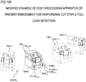
- the staple cartridge 100Jb includes a cut staple full load detection actuator 110Jb and a locking unit 111Jb interlocked with the cut staple full load detection actuator 110Jb. Further, the stapler 1Jb is provided with a locked portion 112Jb with which the locking unit 111Jb abuts.
- the cut staple full load detection actuator 110Jb moves in a direction in which the cut staple full load detection actuator 110Jb protrudes into the cut staple storage unit 6Jb and in a retreating direction.
- the cut staple full load detection actuator 11 0Jb may be configured to be retracted from the inside of the cut staple storage unit 6Jb by being pushed against the cut staple 13A when the cut staple 13A is stored in the cut staple storage unit 6Jb, and cut staple full load detection actuator 110Jb may be configured to move in the direction of protruding and retracting into the inside of the cut staple storage unit 6Jb at a predetermined timing.
- the locking unit 111Jb is interlocked with the cut staple full load detection actuator 110Jb, and in this example, moves by rotating operation between the initial position where the locking unit 111Jb retreats from the lower surface of the staple cartridge 1Jb into the inside and the locked position projecting from the lower surface of the staple cartridge 1Jb.
- the shaft 113Jb of the rotational operation of the locking unit 111Jb is located on the front side in the movement direction in the operation of moving the staple cartridge 100Jb in the direction of detaching the staple partridge 100Jb from the storage unit 20Jb of the stapler 1Jb.
- the locked portion 112Jb protrudes from the lower surface of the storage unit 20Jb into the movement path of the locking unit 111Jb that has moved to the locking position.
- the stapler 1Jb in a state in which the cut staple 13A is not stored in the cut staple storage unit 6Jb, when the cut staple full load detection actuator 110Jb is inserted into the cut staple storage unit 6Jb, the locking unit 111Jb is moved to the initial position where it retreats from the lower surface of the staple cartridge 1Jb to the inside thereof.
- the staple cartridge 100Jb can be freely attached to and detached from the storage unit 20Jb.
- the cut staple full load detection actuator 110Jb In the state in which a predetermined quantity of the cut staple 13A is stored in the cut staple storage unit 6Jb, as illustrated in Fig. 40 , the cut staple full load detection actuator 110Jb is pushed against the cut staple 13A and cannot protrude inside the cut staple storage unit 6Jb. Thus, the cut staple full load detection actuator 110Jb is in state of retreating from the inside of the cut staple storage unit 6Jb. As a result, the locking unit 111Jb moves to the locking position where it protrudes from the lower surface of the staple cartridge 1Jb.
- the staple cartridge 100Jb In the operation of detaching the staple 13A or detaching the staple cartridge 100Jb by replenishing the staple 10A, in order to remove the staple cartridge 100Jb from the stapler 1Jb, the staple cartridge 100Jb is moved in the direction of pulling the staple cartridge 100Jb out of the storage unit 20Jb.
- the locking unit 111Jb rides over the locked portion 112Jb. Therefore, the staple cartridge 100Jb can be detached from the stapler 1Jb.
- the locking unit 111Jb abuts against the locked portion 112Jb, as illustrated in Fig. 41 .
- the locking unit 111Jb cannot ride over the locked portion 112Jb due to the shape of the locking unit 111 Jb.
- the staple cartridge 100Jb cannot be attached to the stapler 1Jb unless the cut staple 13A is discharged from the cut staple storage unit 6Jb. Therefore, it is possible to reliably discharge the cut staple 13A from the cut staple storage unit 6Jb and to recover the cut staple 13A.
- Fig. 42 is a perspective view illustrating an example of the stapler of the tenth embodiment
- Figs. 43 to 46 are side sectional views illustrating an example of the stapler of the tenth embodiment
- a stapler 1K includes a staple ejecting unit 2K which supplies and ejects the staple 10A, and a binding unit 3K that binds the sheet P with the staple 10A, by cutting the staple leg 12A of the staple 10A illustrated in Fig. 3C and by folding the staple leg 12A illustrated in Fig. 3D , in cooperation with the staple ejecting unit 2.
- the stapler 1K includes a sheet pinching unit 4K that pinches the sheet P between the staple ejecting unit 2K and the binding unit 3K.
- the stapler 1K moves in a direction in which the binding unit 3K comes into contact with and separates from the staple ejecting unit 2K in a rotational operation about the shaft 32K as a fulcrum, and pinches and releases the sheet P with the sheet pinching unit 4K.
- the stapler 1K includes a cut unit 30K which cuts the staple leg 12A of the staple 10A penetrating the sheet P at a predetermined length, a cut staple storage unit 6Ka which stores the cut staple 13A cut by the cut unit 30K, and a discharge passage 33K which guides the cut staple 13A cut by the cut unit 30K to the cut staple storage unit 6Ka.
- the feeding unit, the ejecting unit, the clincher unit, and the driving unit of the staple 10A are not illustrated, but the stapler 1K may have the same configuration as the stapler 1A of the first embodiment.
- the cut staple storage unit 6Ka is detachably attached to the stapler 1 K.
- the cut staple storage unit 6Ka is detachably attached to the staple ejecting unit 2K.
- the discharge passage 33K is provided in the binding unit 3K and communicates with the cut unit 30K, and communicates with the cut staple storage unit 6Ka. As a result, the cut staple 13A passing from the cut unit 30K through the discharge passage 33K is stored in the cut staple storage unit 6Ka.
- the cut staple storage unit 6Ka includes an engagement portion 68Ka.
- the engagement portion 68Ka moves up and down by the change in the quantity of the cut staple 13A stored in the cut staple storage unit 6Ka.
- the engagement portion 68Ka is configured so that the surface facing the staple cartridge 100L in the operation of moving the staple cartridge 100K in the direction of attaching to the storage unit 20K of the stapler 1K is substantially perpendicular.
- the fitting portion 68Ka is configured so that the surface facing the staple cartridge 100K in the operation of moving the staple cartridge 100K in the direction of detaching the staple cartridge 100K from the storage unit 20K of the stapler 1K is inclined with respect to the movement direction.
- the stapler 1 K includes a locking pin 115K locked to a locking protrusion 114K provided on the staple cartridge 100K, and a spring 116K which urges the locking pin 115K in the direction of the locking protrusion 114K.
- the engagement portion 68Ka is lowered to the initial position in a state in which the cut staple 13A is not stored in the cut staple storage unit 6Ka.
- the engagement portion 68Ka does not protrude into the storage unit 20K, and the staple cartridge 100K can be freely attached to and detached from the storage unit 20K.
- the staple cartridge 100K is moved in the direction of pulling out the staple cartridge 100K from the storage unit 20K.
- the staple cartridge 100K When the staple cartridge 100K is moved in the direction of pulled out of the storage unit 20K, the staple cartridge 100K rides over the engagement portion 68Ka, while compressing the spring 116K and pushing up the engagement pin 115K, by the shape of the inclined surface of the engagement portion 68Ka Therefore, the staple cartridge 100K can be detached from the stapler 1K.
- the staple cartridge 100K When the staple cartridge 100K is attempted to be attached to the stapler 1K again without discharging the cut staple 13A from the cut staple storage unit 6Ka, the staple cartridge 100K abuts against the engagement portion 68Ka as illustrated in Fig. 46 .
- the staple cartridge 100K In the operation of moving the staple cartridge 100K in the direction of attaching the staple cartridge 100K to the stapler 1 K, the staple cartridge 100K cannot ride over the engagement portion 68Ka due to the shape of the engagement portion 68Ka. As a result, the staple cartridge 100K cannot be attached to the stapler 1 K unless the cut staple 13A is discharged from the cut staple storage unit 6Ka. Therefore, it is possible to reliably discharge the cut staple 13A from the cut staple storage unit 6Ka and to recover the cut staple 13A.
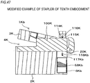
- Figs. 47 to 49 are side sectional views illustrating modified examples of the stapler of the tenth embodiment.
- a stapler 1 Kb of the modified example of the tenth embodiment includes the staple ejecting unit 2K and the binding unit 3K, and a sheet pinching unit 4K which pinches the sheet P between the staple ejecting unit 2K and the binding unit 3K.
- the stapler 1Kb is provided with a cut staple storage unit 6Kb which stores the cut staple 13A cut by the cut unit 30K.
- the cut staple storage unit 6Kb is detachably attached to the staple ejecting unit 2K.
- the cut staple storage unit 6Kb is provided with an engagement portion 68Kb.
- the engagement portion 68Kb moves up and down by the change in the quantity of the cut staple 13A stored in the cut staple storage unit 6Kb.
- the engagement portion 68Kb is configured so that the surface facing the locking pin 117Kb in the operation of moving the cut staple storage unit 6Kb in the direction of attached to the stapler 1Kb is substantially perpendicular.
- the fitting portion 68Ka is configured so that the surface facing the engaging pin 117Kb in the operation of moving the cut staple storage unit 6Kb in the direction of detached from the stapler 1K is inclined with respect to the movement direction.
- the stapler 1Kb is provided with a locking pin 115K locked to the locking protrusion 114K provided on the staple cartridge 100K, and a spring 116K which urges the locking pin 115K in the direction of the locking protrusion 114K.
- the stapler 1Kb is provided with a locking pin 117Kb to which the engagement portion 68Kb is locked, and a spring 118Kb which urges the locking pin 117Kb in the direction of the engagement portion 68Kb.
- the engagement portion 68Kb is lowered to the initial position in a state in which the cut staple 13A is not stored in the cut staple storage unit 6Kb. Therefore, the engagement portion 68Kb does not protrude, and the cut staple storage unit 6Kb can be freely attached and detached.
- the engagement portion 68Kb moves up to the engagement position.
- the cut staple storage unit 6Kb is moved in the direction of pulled out of the stapler 1Kb.
- the engagement portion 68Kb rides over the locking pin 117Kb, while compressing the spring 118Kb and pushing up the locking pin 117Kb by the shape of the slope of the engagement portion 68K. Therefore, the cut staple storage unit 6Kb can be detached from the stapler 1 Kb.
- the engagement portion 68Kb cannot ride over the locking pin 117Kb due to the shape of the engagement portion 68Kb. Accordingly, unless the cut staple 13A is discharged from the cut staple storage unit 6Kb, the cut staple storage unit 6Kb cannot be attached to the stapler 1Kb. Therefore, it is possible to reliably discharge the cut staple 13A from the cut staple storage unit 6Kb and to recover the cut staple 13A.
- Fig. 50 is a perspective view illustrating an example of the stapler of the eleventh embodiment
- Figs. 51 and 52 are side sectional views illustrating an example of the stapler of the eleventh embodiment.
- a stapler 1L of the eleventh embodiment includes the staple ejecting unit 2L which supplies and ejects the staple 10A, and a binding unit 3L that binds the sheet P with the staple 10A, by cutting the staple leg 12A of the staple 10A illustrated in Fig. 3C and by folding the staple leg 12A illustrated in Fig. 3D in cooperation with the staple ejecting unit 2.
- the stapler 1L is provided with a sheet pinching unit 4L which pinches the sheet P between the staple ejecting unit 2L and the binding unit 3L.
- the stapler 1L moves in a direction in which the binding unit 3L comes into contact with and separates from the staple ejecting unit 2L in a rotational operation about the shaft 32L as a fulcrum, and pinches and releases the sheet P with the sheet pinching unit 4L.
- the stapler 1L includes a cut unit 30L which cuts the staple leg 12A of the staple 10A penetrating the sheet P with a predetermined length, a cut staple storage unit 6L which stores the cut staple 13A cut by the cut unit 30L, and a discharge passage 33L which guides the cut staple 13A cut by the cut unit 30L to the cut staple storage unit 6L.
- the feeding unit, the ejecting unit, the clincher unit, and the driving unit of the staple 10A are not illustrated, but the stapler 1L may have the same configuration as the stapler 1 A of the first embodiment.
- the cut staple storage unit 6L is detachably attached to the stapler 1L.
- the cut staple storage unit 6L is detachably attached to the back surface of the staple ejecting unit 2L.
- the staple cartridge 100L is configured to be attachable to and detachable from the stapler 1L by attaching and detaching the cut staple storage unit 6L.
- the discharge passage 33L is provided in the binding unit 3L, communicates with the cut unit 30L, and communicates with the cut staple storage unit 6L. As a result, the cut staple 13A passing from the cut unit 30L through the discharge passage 33L is stored in the cut staple storage unit 6L.
- the cut staple storage unit 6L includes an expansion unit 69L.
- the expansion unit 69L is movable in a direction of being drawn out and stored in the cut staple storage unit 6L, and is provided so that the volume of the cut staple storage unit 6L can be adjusted.
- the stapler 1 L As illustrated in Fig. 51 , by pulling out the expansion unit 69L from the cut staple storage unit 6L, the volume of the cut staple storage unit 6L can be enlarged. Further, as illustrated in Fig. 52 , by storing the expansion unit 69L in the cut staple storage unit 6L, it is possible to reduce the volume of the cut staple storage unit 6L. Accordingly, the storage quantity of the cut staple 13A can be adjusted as necessary.
- Figs. 53 and 54 are perspective views illustrating an example of the stapler of the twelfth embodiment
- Fig. 55 is a perspective view illustrating an example of the cut staple storage unit.
- the stapler 1M includes a staple ejecting unit 2M which supplies and ejects the staple 10A, and a binding unit 3M that binds the sheet P with the staple 10A, by cutting the staple leg 12A of the staple 10A illustrated in Fig. 3C and by folding the staple leg 12A illustrated in Fig. 3D in cooperation with the stapler ejecting unit 2M.
- the stapler 1 M includes a sheet pinching unit 4M which pinches the sheet P between the staple ejecting unit 2M and the binding unit 3M.
- the stapler 1M moves in a direction in which the binding unit 3M comes into contact with and separates from the staple ejecting unit 2M in a rotational operation about the shaft 32M as a fulcrum, and pinches and releases the sheet P with the sheet pinching unit 4M.
- the stapler 1M includes a cut unit 30M that cuts the staple leg 12A of the staple 10A penetrating the sheet P with a predetermined length, a cut staple storage unit 6Ma that stores the cut staple 13A cut by the cut unit 30M, and a discharge passage 33M which guides the cut staple 13A cut by the cut unit 30M to the cut staple storage unit 6Ma.
- the feeding unit, the ejecting unit, the clincher unit, and the driving unit of the staple 10A are not illustrated, but the stapler 1M have the same configuration as the stapler 1A of the first embodiment.
- the cut staple storage unit 6Ma is detachably attached to the stapler 1M.
- the cut staple storage unit 6Ma is detachably attached to the back surface of the staple ejecting unit 2M.
- the shaft protrusion 70Ma is inserted into a receiving unit (not illustrated) of the stapler 1M, and in the operation of attaching and detaching the cut staple storage unit 6Ma to and from the stapler 1M is performed by the rotational operation around the shaft protrusion 70Ma as the shaft.
- the cut staple storage unit 6Ma is detached from the stapler 1M by removing the shaft projection portion 70Ma from the stapler 1M.
- the cut staple storage unit 6Ma includes an locking claw 71Ma locked with the stapler 1M, and an manipulation unit 72Ma provided on the locking claw 71 Ma to release the locking of the locking claw 71Ma.
- the staple cartridge 100M is configured to be attachable to and detachable from the stapler 1 M in a state in which the cut staple storage unit 6Ma is attached to the stapler 1 M.
- the discharge passage 33M is provided in the binding unit 3M, communicates with the cut unit 30M, and communicates with the cut staple storage unit 6Ma. As a result, the cut staple 13A passing from the cut unit 30L through the discharge passage 33L is stored in the cut staple storage unit 6Ma.
- the stapler 1 M when attaching the cut staple storage unit 6Ma, by inserting the shaft protrusion 70Ma into a storage unit (not illustrated) of the stapler 1M and by pushing the cut staple storage unit 6Ma toward the stapler 1M, as illustrated in Fig. 54 , the locking claw 71 Ma is locked with the stapler 1M in a rotational operation around the shaft protrusion 70Ma as a shaft, and as illustrated in Fig. 53 , the cut staple storage unit 6Ma is attached to the stapler 1M.
- the stapler 1 M can prevent the cut staple storage unit 6Ma from being unintentionally disengaged, even if vibration or the like is applied when moving in the post-processing apparatus 502A.
- Figs. 56 and 57 are perspective views illustrating a modified example of the stapler of the twelfth embodiment.
- a stapler 1Mb of the modified example of the twelfth embodiment includes the staple ejecting unit 2M and the binding unit 3M, and a sheet pinching unit 4M which pinches the sheet P between the staple ejecting unit 2M and the binding unit 3M.
- the stapler 1Mb includes a cut staple storage unit 6Mb which stores the cut staple 13A cut by the cut unit 30M, and a discharge passage 33M which guides the cut staple 13A cut by the cut unit 30M to the cut staple storage unit 6Mb.
- the staple cartridge 100M is configured to be attachable to and detachable from the stapler 1M in a state in which the cut staple storage unit 6Mb is attached to the stapler 1M.
- the cut staple storage unit 6Mb is detachably attached to the back surface of the staple ejecting unit 2M.
- the cut staple storage unit 6Mb is attached to and detached from the stapler 1M in a rotational operation about the shaft protrusion (not illustrated) as a fulcrum.
- the cut staple storage unit 6Mb is provided with a locking claw 71 Mb locked with the stapler 1Mb, and a manipulation unit 72Mb which releases the locking of the locking claw 71Mb.
- the manipulation unit 72Mb is provided on one or both side surfaces of the cut staple storage unit 6Mb, and moves the locking claw 71 Mb provided on the lower surface of the cut staple storage unit 6Mb.
- the stapler 1 Mb when the cut staple storage unit 6Mb is attached, by pushing the cut staple storage unit 6Mb in the direction of the stapler 1Mb, as illustrated in Fig. 57 , in the rotational operation of the cut staple storage unit 6Mb, the locking claw 71 Ma is locked to the stapler 1M, and as illustrated in Fig. 56 , the cut staple storage unit 6Mb is attached to the stapler 1 Mb.
- the locking claw 71Mb is retracted to release the locking, and the cut staple storage unit 6Mb is moved in a direction of separating from the stapler 1 Mb.
- the cut staple storage unit 6Mb is detached from the stapler 1 Mb by the rotational operation.
- Figs. 58 and 59 are perspective views illustrating another modified example of the stapler of the twelfth embodiment
- Fig. 60 is a side view illustrating another modified example of the stapler of the twelfth embodiment.
- the stapler 1Mc of the other modified example of the twelfth embodiment is provided with the staple ejecting unit 2M and the binding unit 3M, and a sheet pinching unit 4M which pinches the sheet P between the staple ejecting unit 2M and the binding unit 3M.
- the stapler 1Mc includes a cut staple storage unit 6Mc which stores the cut staple 13A cut by the cut unit 30M, and a discharge passage 33M which guides the cut staple 13A cut by the cut unit 30M to the cut staple storage unit 6Mc.
- the staple cartridge 100M is configured to be attachable to and detachable from the stapler 1M in a state in which the cut staple storage unit 6Mc is attached to the stapler 1M.
- the cut staple storage unit 6Mc is detachably attached to the back surface of the staple ejecting unit 2M.
- the shaft protrusion 70Mc enters a receiving unit 119Mc provided in the lower portion of the stapler 1Mc, and the operation of attaching and detaching the cut staple storage unit 6Mc to and from the stapler 1Mc is performed by the rotational operation around the shaft protrusion 70Mc as a shaft.
- the cut staple storage unit 6Mc is detached from the stapler 1Mc by removing the shaft protrusion 70Mc from the receiving unit 119Mc.
- the cut staple storage unit 6Mc includes a locking claw 71Mc locked to the stapler 1Mc, and a manipulation unit 72Mc provided on the locking claw 71Mc to release locking of the locking claw 71 Mc.
- the shaft protrusion 70Mc is inserted into the receiving unit 119Mc of the stapler 1Mc and the cut staple storage unit 6Mc is moved in the direction of the stapler 1Mc. Then, as illustrated in Figs. 59 and 60 , the locking claw 71Mc is locked with the stapler 1Mc by the rotational operation about the shaft protrusion 70Mc as the shaft, and as illustrated in Fig. 58 , the cut staple storage unit 6Mc is attached to the stapler 1Mc.
- Figs. 61 and 62 are perspective views illustrating another modified example of the stapler of the twelfth embodiment.
- the stapler 1Md of the other modified example of the twelfth embodiment is provided with the staple ejecting unit 2M and the binding unit 3M, and a sheet pinching unit 4M which pinches the sheet P between the staple ejecting unit 2M and the binding unit 3M.
- the stapler 1Md includes a cut staple storage unit 6Md which stores the cut staple 13A cut by the cut unit 30M, and a discharge passage 33M which guides the cut staple 13A cut by the cut unit 30M to the cut staple storage unit 6Md.
- the staple cartridge 100M is configured to be attachable to and detachable from the stapler 1M in a state in which the cut staple storage unit 6Md is attached to the stapler 1M.
- the cut staple storage unit 6Md is detachably attached to the back surface of the staple ejecting unit 2M.
- the cut staple storage unit 6Md is moved in the direction of pulled out to the back side of the stapler 1Md, and the operation of being attached to and detached from the stapler 1Md is performed.
- the cut staple storage unit 6Md has a manipulation unit 72Md which releases the locking of a locking claw (not illustrated) locked with the stapler 1Md on both left and right side surfaces.
- the cut staple storage unit 6Md when the cut staple storage unit 6Md is attached, by pushing the cut staple storage unit 6Md from the back side into the attachment part on the back side of the stapler 1Md, the cut staple storage unit 6Md is attached to the stapler 1 Md as illustrated in Fig. 61 .
- the locking of the locking claw (not illustrated) is released by manipulating the manipulation unit 72Md, and by moving the cut staple storage unit 6Md in the direction of separating from the stapler 1 Md, as illustrated in Fig. 62 , the cut staple storage unit 6Md is detached from the back side of the stapler 1Md.
- Figs. 63 and 64 are perspective views illustrating another modified example of the stapler of the twelfth embodiment
- Fig. 65 is a side sectional view illustrating another modified example of the stapler of the twelfth embodiment.
- a stapler 1 Me of another modified example of the twelfth embodiment is provided with the staple ejecting unit 2M and the binding unit 3M, and a sheet pinching unit 4M which pinches the sheet P between the staple ejecting unit 2M and the binding unit 3M.
- the stapler 1Me includes a cut staple storage unit 6Me which stores the cut staple 13A cut by the cut unit 30M, and a discharge passage 33M which guides the cut staple 13A cut by the cut unit 30M to the cut staple storage unit 6Md.
- the staple cartridge 100M is configured to be attachable to and detachable from the stapler 1M in a state in which the cut staple storage unit 6Md is attached to the stapler 1M.
- the cut staple storage unit 6Me is detachably attached to the back surface of the staple ejecting unit 2M.
- the operation of attaching and detaching the cut staple storage unit 6Me with respect to the stapler 1 Me by the movement in the vertical direction is performed.
- the stapler 1Me has manipulation units 72Me which releases the locking of the locking claw 71 Me locked with the cut staple storage unit 6Me on both of the left and right side surfaces.
- the cut staple storage unit 6Me when the cut staple storage unit 6Me is attached, by moving the cut staple storage unit 6Me downward from the upper side to the attachment site on the back side of the stapler 1 Me, as illustrated in Fig. 63 , the cut staple storage unit 6Me is attached to the stapler 1Me.
- Figs. 66 and 67 are perspective views illustrating an example of the stapler of the thirteenth embodiment
- Figs. 68 and 69 are sectional views of main parts illustrating an example of the stapler of the thirteenth embodiment
- a stapler 1N As illustrated in Figs. 3A and 3B , a stapler 1N according to the thirteenth embodiment is provided with a staple ejecting unit 2N which supplies and ejects the staple 10A, and a binding unit 3N that binds the sheet P with the staple 10A, by cutting the staple leg 12A of the staple 10A illustrated in Fig. 3C and by folding the staple leg 12A illustrated in Fig. 3D in cooperation with the staple ejecting unit 2.
- the stapler 1N is provided with a sheet pinching unit 4N which pinches the sheet P between the staple ejecting unit 2N and the binding unit 3N.
- the stapler 1N moves in a direction in which the binding unit 3N separates from the staple ejecting unit 2N in a rotational operation about the shaft 32N as a fulcrum, and pinches and releases the sheet P with the sheet pinching unit 4N.
- the stapler 1N includes a cut unit 30N which cuts the staple leg 12A of the staple 10A penetrating the sheet P with a predetermined length, a cut staple storage unit 6N which stores the cut staple 13A cut by the cut unit 30N, and a discharge passage 33N which guides the cut staple 13A cut by the cut unit 30N to the cut staple storage unit 6N.
- the feeding unit, the ejecting unit, the clincher unit, and the driving unit of the staple 10A are not illustrated, but the stapler 1N may have the same configuration as the stapler 1A of the first embodiment.
- the cut staple storage unit 6N is detachably attached to the stapler 1N.
- the cut staple storage unit 6N is detachably attached to the back surface of the staple ejecting unit 2N.
- the staple cartridge 100N is configured to be attachable to and detachable from the stapler 1N in a state in which the cut staple storage unit 6N is attached to the stapler 1N.
- the discharge passage 33N is provided in the binding unit 3N, communicates with the cut unit 30N and the discharge port 34N, and communicates with the recovery port 61N of the cut staple storage unit 6N.
- the cut staple 13A passing from the cut unit 30N through the discharge passage 33N is stored in the cut staple storage unit 6N from the recovery port 61N.
- the stapler 1N is provided with a lid 80N in the discharge port 34N of the discharge passage 33N.
- the lid 80N is biased in a direction of closing the discharge port 34N with a spring (not illustrated) by opening and closing the discharge port 34N in a rotational operation about the shaft 81N as a fulcrum.
- the lid 80N is provided with a pressed section 82N that is pressed by the cut staple storage unit 6N on the opposite side across the shaft 81N.
- the cut staple storage unit 6N includes a lid 83N in the recovery port 61N.
- the lid 83N is biased in a direction of closing the recovery port 61 N with a spring (not illustrated) by opening and closing the recovery port 61N with a rotational operation about the shaft 84N as a fulcrum.
- the cut staple storage unit 6N includes a pressing section 85N that presses the pressed section 82N of the lid 80N.
- the pressing section 85N is provided at a position of pressing the pressed section 82N of the lid 80N when the cut staple storage unit 6N is attached to the stapler 1N.
- the pressing section 85N presses the pressed section 82N of the lid 80N.
- the lid 80N opens the discharge port 34N when the pressed section 82N is pressed.
- the lid 80N opens downward, the lid 83N is pressed against the lid 80N, thereby opening the recovery port 61N as illustrated in Fig. 69 .
- the lid 80N of the discharge port 34N and the lid 83N of the recovery port 61N are opened by the operation of attaching the cut staple storage unit 6N to the stapler 1N, and the discharge passage 33N and the cut staple storage unit 6N communicate with each other.
- the lid 80N of the discharge port 34N and the lid 83N of the recovery port 61N are closed by the operation of detaching the cut staple storage unit 6N from the stapler 1N, and even if the cut staple remains in the discharge passage 33N, it is possible to prevent the staple from being discharged to the outside of the stapler 1N.
- Figs. 70 and 71 are side sectional views illustrating main parts of a modified example of the stapler of the thirteenth embodiment.
- the stapler 1N is provided with a lid 80N in the discharge port 34N of the discharge passage 33N.
- the lid 80N is biased in a direction of closing the discharge port 34N with a spring (not illustrated) by opening and closing the discharge port 34N in a rotational operation about the shaft 81N as a fulcrum.
- the lid 80N is provided with a pressed section 82N that is pressed against the cut staple storage unit 6N on the opposite side across the shaft 81N.
- the cut staple storage unit 6N includes a pressing section 85N that presses the pressed section 82N of the lid 80N.
- the pressing section 85N is provided at a position of pressing the pressed section 82N of the lid 80N when the cut staple storage unit 6N is attached to the stapler 1N.
- the pressing section 85N presses the pressed section 82N of the lid 80N.
- the lid 80N opens the discharge port 34N as illustrated in Fig. 70 . Therefore, the lid 80N of the discharge port 34N is opened by the operation of attaching the cut staple storage unit 6N to the stapler 1N, and the discharge passage 33N and the cut staple storage unit 6N communicate with each other.
- the lid 80N of the discharge port 34N is closed by the operation of detaching the cut staple storage unit 6N from the stapler 1N, and even if the cut staple remains in the discharge passage 33N, it is possible to suppress the cut staple from being discharged to the outside of the stapler 1N. Since the lid is not provided in the recovery port 61N of the cut staple storage unit 6N, the stored staple can be discharged from the recovery port 61N.
- Figs. 72 and 73 are side views illustrating an example of the stapler of the fourteenth embodiment
- Figs. 74 to 76 are side sectional views illustrating an example of the stapler of the fourteenth embodiment.
- a stapler 1P of the fourteenth embodiment includes a staple ejecting unit 2P which supplies and ejects the staple 10A, and a binding unit 3P that binds the sheet P with the staple 10A, by cutting the staple leg 12A of the staple 10A illustrated in Fig. 3C and by folding the staple leg 12A illustrated in Fig. 3D in cooperation with the staple ejecting unit 2P.
- the stapler 1 P is provided with a sheet pinching unit 4P which pinches the sheet P between the staple ejecting unit 2P and the binding unit 3P.
- the binding unit 3P moves in a direction in which the binding unit 3P moves toward or away from the staple ejecting unit 2P by the rotational operation, and pinches and releases the sheet P with the sheet pinching unit 4P.
- the stapler 1P includes a cut unit 30P that cuts the staple leg 12A of the staple 10A penetrating the sheet P at a predetermined length, a cut staple storage unit 6P that stores the cut staple 13A cut by the cut unit 30P, and a discharge passage 33 P which guides the cut staple 13A cut by the cut unit 30P to the cut staple storage unit 6P.
- the feeding unit, the ejecting unit, the clincher unit, and the driving unit of the staple 10A are not illustrated, but the stapler I P may have the same configuration as the stapler 1A of the first embodiment.
- the cut staple storage unit 6P is detachably attached to the stapler 1P.
- the cut staple storage unit 6P is detachably attached to the back surface of the staple ejecting unit 2P
- the staple cartridge 100P is configured to be attachable to and detachable from the stapler 1P in a state in which the cut staple storage unit 6P is attached to the stapler 1P.
- the discharge passage 33P is provided in the binding unit 3P, communicates with the cut unit 30P, and the discharge port 34P communicates with the recovery port 61 P of the cut staple storage unit 6P.
- the cut staple 13A passing from the cut unit 30P through the discharge passage 33 P is stored in the cut staple storage unit 6P from the recovery port 61 P.
- the stapler 1P includes a lid 80P in the discharge port 34P of the discharge passage 33P.
- the lid 80P opens and closes the discharge port 34P by rotational operation about the shaft 81 P as a fulcrum.
- the lid 80P includes a pressed section 82P 1 on the other side across the shaft 81P
- the operation of a cam 51P constituting a driving unit for performing pinching of the sheet, ejecting the staple and clinching is transmitted to the pressed section 82P 1 via the link unit 53P, and the lid 80P is opened and closed by the operation of the cam 51 P.
- the cut staple storage unit 6P includes a lid 83P in the recovery port 61 P.
- the lid 83P is biased in a direction of closing the recovery port 61 P with a spring (not illustrated) by opening and closing the recovery port 61 P by the rotational operation about the shaft 84P as a fulcrum.
- the stapler 1P includes a pressing section 34P 2 which opens the lid 83P of the cut staple storage unit 6P at the opening end of the discharge port 34P of the discharge passage 33P
- the discharge port 34P of the discharge passage 33P enters the recovery port 61 P of the cut staple storage unit 6P, and the pressing section 34P 2 projects downward from the shaft 84P of the lid 83P of the cut staple storage unit 6P.
- the lid 83P is pressed by the pressing section 34P 2 by the operation of attaching the cut staple storage unit 6P to the stapler 1P, the recovery port 61 P of the cut staple storage unit 6P is opened, and the lid 83P is held in the open state.
- the pressing section 34P 2 presses the lid 83P.
- the recovery port 61 P opens as illustrated in Fig. 74 .
- the lid 83P of the recovery port 61 P is opened by the operation of attaching the cut staple storage unit 6P to the stapler 1P
- the lid 80P of the discharge port 34P is opened by the operation of binding the sheet with the staple
- the discharge passage 33P and the cut staple storage unit 6P communicate with each other.
- the lid 80P closes the discharge port 34P by the operation of the link unit 53P as illustrated in Fig. 74 .
- the pressing section 34P 2 is separated from the lid 83P, whereby the lid 83P is closed by the force of a spring (not illustrated) as illustrated in Fig. 76 .
- the lid 80P of the discharge port 34P and the lid 83P of the recovery port 61P are closed, and even if the cut staple remains in the discharge passage 33P, it is possible to suppress the staple from being discharged to the outside of the stapler 1P.
- Figs. 77 to 79 are side sectional views illustrating main parts of a modified example of the stapler of the fourteenth embodiment.
- the stapler 1P includes a lid 80P in the discharge port 34P of the discharge passage 33P.
- the lid 80P opens and closes the discharge port 34P by rotational operation about the shaft 81 P as a fulcrum.
- the lid 80P includes a pressed section 82P, on the other side of the shaft 81P.
- the operation of the cam 51 P illustrated in Figs. 72 and 73 is transmitted to the pressed section 82P 1 via the link unit 53P, and lid 80P is opened and closed by the operation of the cam 51 P.
- the cut staple storage unit 6P is attached to the stapler 1P, and when the cam 51 P rotates, as illustrated in Fig. 73 , in the operation of binding the sheet with the staple, the pressed section 82P1 of the lid 80P is pressed by the operation of the link unit 53P to open the discharge port 34P as illustrated in Fig. 78 .
- the lid 80P of the discharge port 34P is opened by the operation of binding the sheet with the staple, and the discharge passage 33P and the cut staple storage unit 6P communicate with each other.
- the lid 80P closes the discharge port 34P by the operation of the link unit 53P.
- the lid 80P of the discharge port 34P is closed, and even if the cut staple remains in the discharge passage 33P. It is possible to prevent the cut staple from being discharged to the outside of the stapler 1 P. Further, since the lid is not provided in the recovery port 61P of the cut staple storage unit 6P, the stored cut staple can be discharged from the recovery port 61 P.
- the lid 80P of the discharge port 34P can be brought into the closed state at the stage in which the cut staple storage unit 6P is attached to the stapler 1P.
- the lid 80P of the discharge port 34P can be closed.
- the lid 80P of the discharge port 34P be closed except at the time of the binding operation. This is to prevent the cut staple from being unintentionally discharged from the discharge port 34P in a state in which the cut staple storage unit 6P is not attached to the stapler 1 P.
- Fig. 80 is a perspective view illustrating a modified example of the cut staple storage unit.
- the cut staple storage unit 6N including the lid 83N and the cut staple storage unit 6P including the lid 83P may be provided with an openable and closable lid 86 for discharging the cut staple. As a result, it is possible to discharge the cut staple by opening the lid 86.
- Figs. 81A and 81B are perspective views illustrating another modified example of the cut staple storage unit.
- a magnet 87 is provided on the bottom surface to absorb the metallic cut staple 13A and prevent scattering.
- the magnetic force of the magnet 87 is released, and it is possible to discharge the cut staple 13A from the recovery ports 61N and 61P.
- Figs. 82A and 82B are side sectional views illustrating another modified example of the cut staple storage unit. If the metallic cut 13A is charged and adsorbed, there is a possibility of difficulty in discharge and an increase in bulk.
- a charging brush 88 is provided in each of the aforementioned cut staple storage units 6 (A to P).
- a ground section 88a is in contact with the staplers 1 (A to P) and is grounded via the staplers 1 (A to N).
- the discharging brush 88 is provided on the recovery port 61 side
- the discharging brush 88 is provided on the bottom side of the cut staple storage unit 6.
- Figs. 83 to 85 are perspective views illustrating another modified example of the cut staple storage unit.
- the cut staple housing section 6 is formed asymmetrically in the lateral direction, and erroneous attachment to the stapler 1 is suppressed.
- the thicknesses of the recovery route 60A L and the recovery route 60A R are changed.
- a fitting groove 89 including a combination of a recess and a protrusion extending in accordance with the attaching and detaching direction with respect to the stapler 1 (Md, Me) is provided, and if it is not aligned with the fitting groove 89, attachment and detachment cannot be performed.
- the mounting direction of the cut staple storage unit 6 from being mistaken, so that the attachment and detachment work can be easily performed.
- Fig. 86 is a configuration diagram illustrating an example of a post-processing apparatus according to the present embodiment.
- the cut staple storage unit 6M is detachable as in the stapler 1M described with reference to Fig. 53
- a stage referred to as a half set
- a pressing guide 90A is provided which is an example of an attachment assisting section that presses the cut staple storage unit 6 against the stapler 1 moving from the first position Pp1 to the second position Pp2.
- the cut staple storage unit 6 is attached to and detached from the stapler 1 at the first position Pp1.
- the first position Pp1 also serves as an operation position for performing an operation of attaching/detaching the cut staple storage unit 6 to/from the stapler 1.
- a position different from the first position Pp1 is set as a home position, attachment and detachment of the cut staple storage unit 6 to and from the stapler 1 is performed at the first position Pp1 as the operation position.
- the home position is a position at which the stapler 1 stands by in preparation for the next job.
- the home position may be the same as and may be different from the manipulation position at which the attachment and detachment of the staple cartridge, and the attachment and detachment of the cut staple storage unit 6 are performed.
- the operation of moving the stapler 1 to the second position Pp2 is performed as the initial operation.
- the cut staple storage unit 6 is pressed in the direction of the stapler 1 by the pressing guide 90A, and it is attached at the regular position. Therefore, even when there is an erroneous operation in which the cut staple storage unit 6 is not attached to the regular position, the cut staple storage unit 6 can be attached to the regular position in the initial operation before performing the binding operation. Therefore, it is possible to reliably store the cut staple in the cut staple storage unit 6.
- Figs. 87A and 87B are configuration diagrams illustrating modified examples of the post-processing apparatus of the present embodiment
- a pressing section 91A as an example of a mounting assistance unit for pressing the cut staple storage unit 6 against to the stapler 1 stopped at the first position Pp1 is provided on the lid 505A.
- the post-processing apparatus 502A opens the lid 505A to attach and detach the cut staple storage unit 6. Even when the attachment of the cut staple storage unit 6 is insufficient, as illustrated in Fig. 87B , by closing the lid 505A, the cut staple storage unit 6 is pressed in the direction of the stapler 1 by the pressing section 91A, and is attached at the regular position. Therefore, even when there is an erroneous operation in which the cut staple storage unit 6 is not attached to the regular position, the cut staple storage unit 6 can be attached to the regular position by the operation of closing the lid 505A. Therefore, it is possible to reliably store the cut staple in the cut staple storage unit 6.
- Figs. 88A and 88B are configuration diagrams illustrating another modified example of the post-processing apparatus of the present embodiment.
- the post-processing apparatus 502A illustrated in Figs. 88A and 88B is provided with a regulating unit 92A which regulates the closing of the lid 505A when the cut staple storage unit 6 is insufficiently mounted or is not attached.
- the regulating unit 92A is displaced by the rotational operation about the shaft 93A as a fulcrum.
- the first position Pp1 is set to the home position of the stapler 1
- the regulating unit 92A is pressed against the cut staple storage unit 6, and is retracted from the path of opening and closing the lid 505A.
- the lid 505A can be closed.
- the regulating unit 92A enters the attaching position of the cut staple storage unit 6 in the stapler 1, and the lid 505A protrudes into the opening and closing path. As a result, the lid 505A cannot be closed.
- Figs. 89A to 89C are configuration diagrams illustrating another modified example of the post-processing apparatus of the present embodiment.
- an operation position OP of the stapler 1 is provided outside the first position Pp1.
- the stapler 1 is moved from the first position Pp1 to the operating position OP.
- the operation position OP the direction of the stapler 1 is rotated at a position outside the first position Pp1 so that the cut staple storage unit 6 faces the lid 505A side.
- Fig. 89B as the operation position OP, the direction of the stapler 1 is rotated at a position outside the first position Pp1 so that the cut staple storage unit 6 faces the lid 505A side.
- the direction of the stapler 1 is rotated at the first position Pp1 so that the cut staple storage unit 6 faces the lid 505A side.
- the first position Pp1 may also serve as the home position HP.
- Fig. 90 is a block diagram illustrating another modified example of the post-processing apparatus of the present embodiment
- Fig. 91 is a perspective view illustrating a modified example of the cut staple storage unit of the present embodiment.
- the stapler 1 since the stapler 1 is obliquely attached, a space E corresponding to the inclination of the stapler 1 is opened on the back side of the stapler 1.
- the expansion unit 69Q is provided so that it can be opened and closed by the rotational operation about the shaft 69Q 1 as a fulcrum.
- the expansion unit 69Q is opened so that the expansion unit 69Q is substantially vertical in accordance with the inclination of the stapler 1, and the expansion unit 69Q is fixed by the position fixing member 69Q 2 made up of a screw or the like.
- the position fixing member 69Q 2 made up of a screw or the like.
- Figs. 92 and 93 are side views illustrating an example of the stapler of the first embodiment that performs the cut staple full load detection
- Fig. 94 illustrates an example of the stapler of the first embodiment that performs the staple full load detection
- Fig. 95 is a configuration diagram illustrating an operation example of the stapler of the first embodiment that performs the cut staple full load detection.
- the stapler 1Ra is provided with a staple ejecting unit 2R which supplies and ejects the staple 10A, and a binding unit 3R that binds the sheet P with the staple 10A, by cutting the staple leg 12A of the staple 10A and by folding the staple leg 12A illustrated in Fig. 3D in cooperation with the staple ejecting unit 2R.
- the stapler 1Ra is provided with a sheet pinching unit 4R which pinches the sheet P between the staple ejecting unit 2R and the binding unit 3R.
- the binding unit 3R moves in a direction in which the binding unit 3R comes into contact with and separates from the staple ejecting unit 2R by the rotational operation, and pinches and releases the sheet P by the sheet pinching unit 4R.
- the stapler 1Ra includes a cut unit 30R which cuts the staple leg 12A of the staple 10A penetrating the sheet P with a predetermined length, a cut staple storage unit 6R which stores the cut staple 13A cut by the cut unit 30R, and a discharge passage 33R (a discharge unit) which guides the cut staple 13A cut by the cut unit 30R to the cut staple storage unit 6R.
- the feeding unit, the ejecting unit, the clincher unit, and the driving unit of the staple 10A are not illustrated, but the stapler 1 Ra may have the same configuration as the stapler 1 A of the first embodiment.
- the cut staple storage unit 6R is detachably attached to the stapler 1Ra.
- the cut staple storage unit 6R is detachably attached to the back surface of the staple ejecting unit 2R.
- the staple cartridge 100R is configured to be attachable to and detachable from the stapler 1Ra in a state in which the cut staple storage unit 6R is attached to the stapler 1 Ra.
- the discharge passage 33R is provided in the binding unit 3R, communicates with the cut unit 30R, and communicates with the recovery port 61 R of the cut staple storage unit 6R. As a result, the cut staple 13A passing from the cut unit 30R through the discharge passage 33R is stored in the cut staple storage unit 6R.
- the stapler 1 Ra and the post-processing apparatus 502A include a cut staple quantity detection unit 94R.
- the cut staple quantity detection unit 94R is an example of the cut staple full load detection unit, and includes contact movable units 95Ra L and 95Ra R , sensors 96R L and 96R R for detecting the contact movable units 95Ra L and 95Ra R , and springs 97Ra L and 97Ra R for urging the contact movable units 95Ra L and 95Ra R .
- the contact movable unit 95Ra L protrudes to one recovery passage 60R L of the cut staple storage unit 6R from the side, and is provided so as to be movable in the vertical direction along the stacking direction of the cut staple 13A.
- the contact movable unit 95Ra L is pressed downward by the spring 97Ra L .
- the sensor 96R L detects whether or not the quantity of the cut staple 13A is full, by detecting the presence or absence of the contact movable unit 95Ra L .
- the sensor 96R L is located at a position of detecting the contact movable unit 95Ra L moved to the non-full load position.
- the contact movable unit 95Ra R projects laterally from the other recovery passage 60R R of the cut staple storage unit 6R, and is provided so as to be movable in the vertical direction along the stacking direction of the cut staple 13A.
- the contact movable unit 95Ra R is pressed downward by the spring 97Ra R .
- the sensor 96R detects whether or not the quantity of the cut staple 13A is full, by detecting the presence or absence of the contact movable unit 95Ra R .
- the sensor 96R is provided at a position of detecting the contact movable unit 95Ra R moved to the non-full load position.
- the operation of the cam 51R forming the driving unit for pinching the sheet, driving the staple, and clinching is transmitted via the link unit 53R L , and the contact movable unit 95Ra L is raised by the operation of the cam 51R.
- the operation of the cam 51 R forming the driving unit for pinching the sheet, driving the staple, and clinching is transmitted via the link unit 53R R , and the contact movable unit 95Ra R is raised by the operation of the cam 51 R.
- the contact movable unit 95Ra L is pressed downward by the spring 97Ra L , is moved to the non-full load detection position, and is detected by the sensor 96R L .
- the contact movable unit 95Ra R is pressed downward by a spring 97Ra R , is moved to the non-full load detection position, and is detected by the sensor 96R. Therefore, it is possible to detect that the quantity of the cut staple 13A is not full.
- the contact movable unit 95Ra L cannot descend to the non-full load detection position, stops at the raised position, and is not detected by the sensor 96R L .
- the contact movable unit 95Ra R cannot descend to the non-full load detection position, stops at the raised position and is not detected by the sensor 96R. Therefore, it is possible to detect that the quantity of the cut staple 13A is full.
- the stapler 1Ra reports this situation to the post-processing apparatus 502A illustrated in Fig.
- the stapler 1Ra is in a tilted state as illustrated in Fig. 95 , depending on the position of the stapler 1Ra.
- the loading height of the cut staple 13A is lowered on the one recovery passage 60R L side of the cut staple storage unit 6R. Therefore, the contact movable unit 95Ra L descends to the non-full load detection position and is detected by the sensor 96R L .
- the loading height of the cut staple 13A rises.
- the contact movable unit 95Ra R cannot descend to the non-full load detection position, stops at the raised position, and is not detected by the sensor 96R. Therefore, even when the stapler 1Ra is inclined, it is possible to accurately detect whether or not the quantity of the cut staple 13A is full. That is, along with the inclination of the stapler 1Ra, the direction of the cut staple storage unit 6R also changes, and the loading height of the cut staple 13A changes in accordance with the change in the direction of the cut staple storage unit 6R.
- the Contact movable unit 95Ra L and the contact movable unit 95Ra R detect the quantity of the cut staple 13A in accordance with the loading height of the changing cut staple 13A.
- the contact movable units 95Ra L and 95Ra R are not detected. This makes it possible to perform the full load detection of the cut staple, the presence or absence of the cut staple storage unit 6R, that is, the detection of attachment and detachment of the cut staple storage unit 6R by the same detection unit.
- Figs. 96 and 97 are side views illustrating modified examples of the stapler of the first embodiment that performs the cut staple full load detection
- Fig. 98 is a modified example of the stapler of the first embodiment that performs the cut staple full load detection
- Fig. 99 is a configuration diagram illustrating an operation example of the stapler of the modified example of the first embodiment that performs the cut staple full load detection.
- the stapler 1Rb of the modified example includes the staple ejecting unit 2R and the binding unit 3R, and has a sheet pinching unit 4R that pinches the sheet P between the staple ejecting unit 2R and the binding unit 3R.
- the stapler 1Rb includes a cut staple quantity detection unit 94R.
- the cut staple quantity detection unit 94R is an example of a cut staple full load detection unit, and includes contact movable units 95Rb L and 95Rb R , sensors 96R L and 96R R for detecting the contact movable units 95Rb L and 95Rb R , and springs 97Rb L and 97Rb R for urging the contact movable units 95Rb L and 95Rb R .
- the contact movable unit 95Rb L enters from the one recovery passages 60R L of the cut staple storage unit 6R from the recovery port 61 R and protrudes from above, and is movable in the vertical direction along the stacking direction of the cut staple 13A.
- the contact movable unit 95Rb L is pressed downward by the spring 97Rb L .
- the sensor 96R L detects whether or not the quantity of the cut staple 13A is full by detecting the presence or absence of the contact movable unit 95Rb L .
- the sensor 96R L is provided at a position for detecting the contact movable unit 95Rb L that has moved to the non-full load position.
- the contact movable unit 95Rb R enters the other recovery passage 60R R of the cut staple storage unit 6R from the recovery port 61R, protrudes from the upper side, and is movable in the vertical direction along the stacking direction of the cut staple 13A.
- the contact movable unit 95Rb R is pressed downward by the spring 97Rb R .
- the sensor 96R detects whether or not the quantity of the cut staple 13A is full by detecting the presence or absence of the contact movable unit 95Rb R .
- the sensor 96R is provided at a position for detecting the contact movable unit 95Rb R that has moved to the non-full load position.
- the operation of the cam 51 R constituting the driving unit for pinching the sheet, driving the staple, and clinching is transmitted to the contact movable unit 95Rb L via the link unit 53R L , and he contact movable unit 95Rb L is moved up and down by the operation of the cam 51R.
- the operation of the cam 51 R constituting the driving unit for pinching the sheet, driving the staple, and clinching is transmitted to the contact movable unit 95Rb R via the link unit 53R R , and he contact movable unit 95Rb R is moved up and down by the operation of the cam 51R.
- the contact movable unit 95Rb L is pressed downward by the spring 97Rb L , is and moved to the non-full load detection position, and is detected by the sensor 96R L . Further, the contact movable unit 95Rb R is formed by a spring 97Rb R , is moved to the non-full load detection position, and is detected by the sensor 96R. Therefore, it is possible to detect that the quantity of the cut staple 13A is not full.
- the contact movable unit 95Rb L cannot descend to the non-full load detection position, stops at the raised position, and is not detected by the sensor 96R L . Further, the contact movable unit 95Rb R cannot descend to the non-full load detection position, stops at the raised position, and is not detected by the sensor 96R. Therefore, it is possible to detect that the quantity of the cut staple 13A is full.
- the stapler 1Rb is inclined as illustrated in Fig. 99 .
- the loading height of the cut staple 13A is lowered on the side of the recovery passage 60R L of the cut staple storage unit 6R. Therefore, the contact movable unit 95Rb L descends to the non-full load detection position and is detected by the sensor 96R L .
- the loading height of the cut staple 13A increases.
- the contact movable unit 95Rb R cannot descend to the non-full load detection position, stops at the raised position, and is not detected by the sensor 96R. Therefore, even when the stapler 1 Rb is inclined, it is possible to accurately detect whether or not the quantity of the cut staple 13A is full.
- Figs. 100 and 101 are side views illustrating another modified example of the stapler of the first embodiment that performs the cut staple full load detection
- Fig. 102 is a side view of another modified example of the stapler of the first embodiment
- Fig. 103 is a configuration diagram illustrating an operation example of a stapler according to another modified example of the first embodiment that performs the cut staple full load detection.
- the stapler 1Rc of another modified example includes a staple ejecting unit 2R and a binding unit 3R, and a sheet pinching unit 4R which pinches the sheet P between the staple ejecting unit 2R and the binding unit 3R.
- the stapler 1Rc includes a cut staple quantity detection unit 94R.
- the cut staple quantity detection unit 94R is an example of a cut staple full load detection unit, and includes contact movable units 95Rc L and 95Rc R , sensors 96R L and 96R R for detecting the contact movable units 95Rc L and 95Rc R , links 98Rc L and 98Rc R for displacing the contact movable units 95Rc L and 95Rc R , and springs 97Rc L and 97Rc R for urging the contact movable units 95Rc L and 95Rc R via the links 98Rc L and 98Rc R .
- the contact movable unit 95Rc L protrudes from the side to from the one recovery passage 60RL of the cut staple storage unit 6R and is movable in the front-rear direction.
- the link 98Rc L rotates around the shaft 99Rc L as a fulcrum, and moves the contact movable unit 95Rc L in the front-rear direction.
- the contact movable unit 95Rc L is pushed rearward by the spring 97Rc L via the link 98Rc L .
- the sensor 96R L detects whether or not the quantity of the cut staple 13A is full, by detecting the presence or absence of the contact movable unit 95Rc L .
- the sensor 96R L is provided at a position which detects the contact movable unit 95Rc L that has moved to the non-full load position.
- the contact movable unit 95Rc R protrudes from the side of the other recovery passage 60R R of the cut staple storage unit 6R and is movable in the front-rear direction.
- the link 98Rc R rotates about the shaft 99Rc R as a fulcrum, and moves the contact movable unit 95Rc R in the front-rear direction.
- the contact movable unit 95Rc R is pressed rearward by the spring 97Rc R via the link 98Rc R .
- the sensor 96R detects whether or not the quantity of the cut staple 13A is full, by detecting the presence or absence of the contact movable unit 95Rc R . In this example, the sensor 96R detects the contact movable unit 95Rc R that has moved to the non-full load position.
- the operation of the cam 51R constituting the driving unit for pinching the sheet, driving the staple, and clinching is transmitted to the contact movable unit 95Rc L via the link unit 53R L and the link 98Rc L , and the contact movable unit 95Rc L is moved forward and backward by the operation of the cam 51R. That is, when the link 98Rc L is rotated by the cam 51 R and the link unit 53R L , the contact movable unit 95Rc L moves by being pressed forward by the spring 100R L
- the spring force of the spring 97Rc L is provided to be larger than the spring force of the spring 100R L .
- the contact movable unit 95Rc L stands by in the rear part by the spring force of the spring 100R L .
- the operation of the cam 51 R constituting the driving unit for pinching the sheet, driving up the staple, and clinching is transmitted to the contact movable unit 95Rc R via the link unit 53R R and the link 98Rc R , and the contact movable unit 95Rc R moves backward and forward by the operation of the cam 51R. That is, when the link 98Rc R is rotated by the cam 51 R and the link unit 53R R , the contact movable unit 95Rc R moves by being is pressed forward by the spring 100R R .
- the spring force of the spring 97Rc R is provided to be larger than the spring force of the spring 100R R .
- the contact movable unit 95Rc L is pressed rearward by the spring 97Rc L , is moved to the non-full load detection position, and is detected by the sensor 96R L .
- the contact movable portion 95Rc R is pressed rearward by the spring 97Rc R , is moved to the non-full load detection position, and is detected by the sensor 96R. Therefore, it is possible to detect that the quantity of the cut staple 13A is not full.
- the contact movable unit 95Rc L cannot move to the non-full load detection position, stops at the position moved forward, and is not detected by the sensor 96R L . Further, the contact movable unit 95Rc R cannot move to the non-full load detection position, stops at the position moved forward, and is not detected by the sensor 96R. Therefore, it is possible to detect that the quantity of the cut staple 13A is full.
- the stapler 1Rc is inclined as illustrated in Fig. 103 .
- the loading height of the cut staple 13A is lowered on the side of one recovery passage 60R L of the cut staple storage unit 6R. Therefore, the contact movable unit 95Rc L moves to the non-full load detection position and is detected by the sensor 96R L .
- the loading height of the cut staple 13A rises.
- the contact movable unit 95Rc R cannot move to the non-full load detection position, stops at the position moved forward, and is not detected by the sensor 96R. Therefore, even when the stapler 1Rc is inclined, it is possible to accurately detect whether or not the quantity of the cut staple 13A is full.
- Figs. 104 and 105 are side views illustrating an example of a stapler according to a second embodiment that performs the cut staple full load detection
- Fig. 106 illustrates an example of a stapler according to a second embodiment that performs the cut staple full load detection
- Figs. 107 to 111 are configuration diagrams illustrating an operation example of the stapler of the second embodiment that performs the cut staple full load detection.
- the stapler I Rd includes a staple ejecting unit 2R, a binding unit 3R, and a sheet pinching unit 4R which pinches the sheet P between the staple ejecting unit 2R and the binding unit 3R.
- the stapler 1 Rd includes a cut staple quantity detection unit 94R.
- the cut staple quantity detection unit 94R is an example of the cut staple full load detection unit, and includes contact movable units 95Rd L and 95Rd R , a sensor 96R L for detecting the contact movable unit 95Rd L , links 98Rd L and 98Rd R for displacing the contact movable units 95Rd L and 95Rd R , and springs 97Rd L and 97Rd R for biasing the movable contact portions 95Rd L and 95Rd R .
- the contact movable unit 95Rd L protrudes from the side to from the one recovery passage 60R L of the cut staple storage unit 6R and is provided so as to be movable in the vertical direction along the stacking direction of the cut staple 13A.
- the link 98Rd L rotates about the shaft 99Rd L as a fulcrum, and moves the contact movable unit 95Rd L in the vertical direction.
- the contact movable unit 95Rd L is pressed downward by the spring 97Rd L .
- the sensor 96R L detects whether or not the quantity of the cut staple 13A is full by detecting the presence or absence of the contact movable unit 95Rd L .
- the sensor 96R L is provided at a position for detecting the contact movable unit 95Rd L moved to the non-full load position.
- the contact movable unit 95Rd R protrudes from the side to from the other recovery passage 60R R of the cut staple storage unit 6R and is movable in the vertical direction along the stacking direction of the cut staple 13A.
- the link 98Rd R rotates about the shaft 99Rd R as a fulcrum, and moves the contact movable unit 95Rd R in the vertical direction.
- the contact movable unit 95Rd R is pressed downward by the spring 97Rd R .
- the operation of the cam 51 R constituting the driving unit for pinching the sheet, driving the staple, and clinching is transmitted to the contact movable unit 95Rd L via the link unit 53R L and the link 98Rd L , and the contact movable unit 95Rd L moves upward and downward by the operation of the cam 51R.
- the operation of the cam 51R constituting the driving unit for pinching the sheet, ejecting the staple, and clinching is transmitted to the contact movable unit 95Rd R via the link unit 53R R and the link 98Rd R , and moves upward and downward by the operation of the cam 51 R.
- the link 98Rd L and the link 98Rd R are connected and linked by a shaft 98R 1 .
- the contact movable unit 95Rd L is pressed downward by the spring 97Rd L , is moved to the non-full load detection position and is detected by the sensor 96R L . Further, since the link 98Rd L and the link 98Rd R are linked with each other by the shaft 98R 1 , the contact movable unit 95Rd R is pressed downward by the spring 97Rd R , and moves to the non-full load detection position. Therefore, it is possible to detect that the quantity of the cut staple 13A is not full.
- the contact movable unit 95Rd L stops at the position moved upward without moving downward to the non-full load detection position, and is not detected by the sensor 96R L . Also, as illustrated in Fig. 110 , the contact movable unit 95Rd R stops at the position moved upward without moving downward to the non-full load detection position. Therefore, it is possible to detect that the quantity of the cut staple 13A is full.
- the stapler 1Rd is in a tilted state as illustrated in Fig. 111 .
- the recovery passage 60R R side of the cut staple storage unit 6R the loading height of the cut staple 13A becomes higher. Therefore, the contact movable unit 95Rd R stops at the position moved upward without moving to the non-full load detection position.
- the loading height of the cut staple 13A decreases on the recovery passage 60R L side of the cut staple storage unit 6R.
- the link 98Rd L and the link 98Rd R are connected and linked by the shaft 98R 1 , irrespective of the loading height of the cut staple 13A, the contact movable unit 95Rd L stops at the position moved upward without moving to the non-full load detection position, and is not detected by the sensor 96R L . This makes it possible to accurately detect whether or not the quantity of the cut staple 13A is full by a single sensor, regardless of the direction of the inclination of the stapler 1Rd.
- Figs. 112 and 113 are side views illustrating modified examples of the stapler of the second embodiment that performs the cut staple full load detection
- Fig. 114 illustrates a modified example of the stapler of the second embodiment that performs the full staple load detection
- Figs. 115 to 119 are configuration diagrams illustrating an operation example of a stapler according to a modified example of the second embodiment that performs the cut staple full load detection.
- the stapler 1 Re includes a staple ejecting unit 2R and a binding unit 3R, and a sheet pinching unit 4R which pinches the sheet P between the staple ejecting unit 2R and the binding unit 3R
- the stapler 1Rd includes a cut staple quantity detection unit 94R.
- the cut staple quantity detection unit 94R is an example of the cut staple full load detection unit, and includes contact movable units 95Re L and 95Re R , a sensor 96R L for detecting the contact movable unit 95Re L , links 98Re L and 98Re R for displacing the contact movable units 95Re L and 95Re R , and Springs 97Re L and 97Re R for biasing the contact movable units 95Re L and 95Re R via the links 98Re L and 98Re R .
- the contact movable unit 95Re L protrudes from the side to from one recovery passage 60R L of the cut staple storage unit 6R and is movable in the front-rear direction.
- the link 98RL rotates about the shaft 99Re L as a fulcrum, and moves the contact movable unit 95Re L in the front-rear direction.
- the contact movable unit 95Re L is pressed rearward by the spring 97Re L via the link 98Re L .
- the sensor 96R L detects whether or not the quantity of the cut staple 13A is full, by detecting the presence or absence of the contact movable unit 95Re L .
- the sensor 96R L is provided at a position that detects the contact movable unit 95Re L moved to the non-full load position.
- the contact movable unit 95Re R protrudes from the side to the other recovery passage 60R R of the cut staple storage unit 6R and is movable in the front-rear direction.
- the link 98Re R rotates about the shaft 99Re R as a fulcrum, and moves the contact movable unit 95Re R in the front-rear direction.
- the contact movable unit 95Re R is pressed rearward by the spring 97Re R via the link 98Re R .
- the operation of the cam 51R constituting the driving unit for pinching the sheet, ejecting the staple, and clinching is transmitted to the contact movable unit 95Re L via the link unit 53R L and the link 98Re L , and moves forward and backward by the operation of the cam 51R. That is, when the link 98Re L is rotated by the cam 51R and the link unit 53R L , the contact movable unit 95Re L moves by being pressed forward by the spring 100R L .
- the spring force of the spring 97Re L is larger than the spring force of the spring 100R L .
- the operation of the cam 51 R constituting the drive unit for pinching the sheet, ejecting the staple and clinching is transmitted to the contact movable unit 95Re R via the link unit 53R R and the link 98Re R , and moves back and forth by the operation of the cam 51R. That is, when the link 98Re R is rotated by the cam 51R and the link unit 53R R , the contact movable unit 95Re R moves forward by being pressed forward by the spring 100R R .
- the spring force of the spring 97Re R is larger than the spring force of the spring 100R R .
- the contact movable unit 95Re R stands by in the rear by the spring force of the spring 100R R .
- the link 98Re L and the link 98Re R are connected and linked with each other by the shaft 98R 1 .
- the contact movable unit 95Re L is pressed rearward by the spring 97Re L via the link 98Re L , moves to the non-full load detection position, and is detected by the sensor 96R L . Since the link 98Re L and the link 98Re R are connected and linked by the shaft 98R 1 , the contact movable unit 95Re R is pressed rearward by the spring 97Re R via the link 98Re R and moves to the non-full load detection position. Therefore, it is possible to detect that the quantity of the cut staple 13A is not full.
- the contact movable unit 95Re L stops at a position moved forward without moving to the non-full load detection, and is not detected by the sensor 96R L .
- the contact movable unit 95Re R stops at a position moved forward without moving to the non-full load detection position. Therefore, it is possible to detect that the quantity of the cut staple 13A is full.
- the stapler 1Re is in an inclined state as illustrated in Fig. 119 .
- the recovery passage 60R R side of the cut staple storage unit 6R the loading height of the cut staple 13A becomes high. Therefore, the contact movable unit 95Re R stops at a position moved forward, without moving to the non-full load detection position.
- the loading height of the cut staple 13A decreases on the recovery passage 60R L side of the cut staple storage unit 6R.
- the link 98Re L and the link 98Re R are connected and linked by the shaft 98R 1 . Therefore, irrespective of the loading height of the cut staple 13A, the contact movable unit 95Re L stops at a position moved forward without moving to the non-full load detection position, and is not detected by the sensor 96R L . This makes it possible to accurately detect whether or not the quantity of cut staples 13A is full by a single sensor, regardless of the direction of inclination of the stapler 1 Re.
- Figs. 120 and 121 are configuration diagrams illustrating an example of a stapler according to another embodiment that performs the cut staple full load detection.
- the contact movable units 95L and 95R are configured to protrude and retreat from the inside of each of the recovery passages 60L and 60R of the cut staple storage unit 6R.
- the contact movable units 95L and 95R are configured to protrude and retract from the outside of each of the recovery passages 60L and 60R of the cut staple storage unit 6R.
- Figs. 122 to 127B are configuration diagrams illustrating modified examples of the stapler according to another embodiment that performs the cut staple full load detection.
- the sensor 96Rf for detecting metal is arranged outside a part through which the cut staple passes in the cut staple storage unit 6R. By counting the number of the cut staples from the output of the sensor 96Rf, it is possible to detect that the quantity of the cut staple is full and to detect the approximate value of the remaining number of cut staples that can be stored.
- a movable unit 95Rg which opens and closes the cut staple storage unit 6R, and an actuator 96Rg for operating the movable unit 95Rg are provided.
- a fixed quantity of the cut staple 13A is accumulated on the movable unit 95Rg such as a predetermined number of binding operations with the movable unit 95Rg closed, as illustrated in Fig. 123B , the movable unit 95Rg is opened by the actuator 96Rg. This makes it possible to detect that the quantity of the cut staple is full and to determine the approximate value of the remaining number of cut staples that can be stored, from the number of operations of the actuator 96Rg.
- the cut staple storage unit 6R is formed by an elastic body, and a movable unit 95Rh that operates by deformation of the cut staple storage unit 6R due to the storage of the cut staple 13A, and a sensor 96Rh that detects the presence or absence of the movable unit 95Rh are included.
- the movable unit 95Rh is not detected by the sensor 96Rh in a state in which the loading height of the cut staple 13A does not reach the full load detection position.
- Fig. 124A the movable unit 95Rh is not detected by the sensor 96Rh in a state in which the loading height of the cut staple 13A does not reach the full load detection position.
- the movable unit 95Rh is operated by the deformation of the cut staple storage unit 6R, and the movable unit 95Rh is detected by the sensor 96Rh. As a result, it is possible to detect that the quantity of the cut staple is full.
- the cut staple storage unit 6R is supported to move upward and downward by a spring 6Ri, and a movable unit 95Ri that operates by displacement of the cut staple storage unit 6R due to a change in weight due to the storage of the cut staple 13A, and a sensor 96Ri for detecting presence or absence of the movable unit 95Ri.
- a spring 6Ri a movable unit 95Ri that operates by displacement of the cut staple storage unit 6R due to a change in weight due to the storage of the cut staple 13A
- a sensor 96Ri for detecting presence or absence of the movable unit 95Ri.
- the cut staple storage unit 6R descends to the detection position by the weight of the cut staple 13A, and the movable unit 95Ri is detected by the sensor 96Ri. As a result, it is possible to detect that the quantity of the cut staple is full.
- a movable unit 95Rj displaced by the weight of the cut staple 13A, and a sensor 96Rg for detecting the presence or absence of the movable unit 95Rj.
- a sensor 96Rg for detecting the presence or absence of the movable unit 95Rj.
- the cut staple storage unit 6R is supported by the spring 6Rk 1 so as to be capable of ascending and descending by rotational operation about the shaft 6Rk 2 as a fulcrum, and the movable unit 95Rk that operates by the displacement of the cut staple storage unit 6R due to the storage of the cut staple 13A, and a sensor 96Rk for detecting the presence or absence of the movable unit 95Rk are included.
- the spring 6Rk 1 so as to be capable of ascending and descending by rotational operation about the shaft 6Rk 2 as a fulcrum
- the movable unit 95Rk that operates by the displacement of the cut staple storage unit 6R due to the storage of the cut staple 13A
- a sensor 96Rk for detecting the presence or absence of the movable unit 95Rk
- the cut staple storage unit 6R when the cut staple 13A is not stored or the storage quantity is small, the cut staple storage unit 6R is pushed up to the initial position or the vicinity of the initial position by the spring 6Rk 1 , and the movable unit 95 is not detected by the sensor 96Rk.
- the cut staple storage unit 6R descends to the detection position by the weight of the cut staple 13A, and the movable unit 95Rk is detected by the sensor 96Rk. As a result, it is possible to detect that the quantity of the cut staple is full.
- Figs. 128 to 129B are configuration diagrams illustrating modified examples of the stapler according to another embodiment that performs the cut staple full load detection.
- Figs. 125A and 125B and Figs. 127A and 127B in the configuration in which the cut staple storage unit 6R can move upward and downward and the full load is detected by the weight of the cut staple 13A, if the cut staple storage unit 6R vibrates by vibration due to movement of the stapler 1 or the like, it may adversely affect the movement operation when moving the stapler 1. There is a possibility of misdetection of full load and non-full load.
- the lock portion 6Rm 1 For regulating the lifting and lowering of the cut staple storage unit 6R and releasing the regulation, an induction unit 6Rm 2 for operating the lock unit 6Rm 1 , and a guide unit 6Rm 3 for operating the induction unit 6Rm 2 .
- the induction unit 6Rm 2 is pushed up by the shape of the guide unit 6Rm 3 to release the regulation of ascending and descending at the locking unit 6Rm 1 of the cut staple storage unit 6R as illustrated in Fig. 129A .
- the full load can be detected with the weight of the cut staple 13A at the home position HP which is not accompanied by the binding operation.
- the induction unit 6Rm 2 descends due to the shape of the guide unit 6Rm 3 , and as illustrated in Fig. 129B , the ascending and descending of the cut staple storage unit 6R are regulated by the lock unit 6Rm 1 . Therefore, when the stapler 1 moves in accordance with the binding operation, the cut staple storage unit 6R does not move upward and downward. Therefore, it is possible to suppress the full load and non-full load error detection due to unnecessary ascending and descending of the cut staple storage unit 6R. Further, the lock portion 6Rm 1 may not be necessarily provided.
- Figs. 130 and 131 are configuration diagrams illustrating modified examples of the stapler according to another embodiment that performs the cut staple full load detection.
- the cut staple storage unit 6R is provided with the movable unit 95Rn that moves up and down with the storage of the cut staple 13A, and a scale 6Rn that is a measure of the storage quantity of the cut staple 13 by the position of the movable unit 95Rn.
- the cut staple storage unit 6R is provided with the movable unit 95Rn that moves up and down with the storage of the cut staple 13A, and a scale 6Rn that is a measure of the storage quantity of the cut staple 13 by the position of the movable unit 95Rn.
- the cut staple storage unit 6R is made of a transparent material so that the inside thereof can be visually recognized, and a scale 6Rn serving as a measure for the quantity of storage of the cut staple 13 is provided in the cut staple storage unit 6R.
- a scale 6Rn serving as a measure for the quantity of storage of the cut staple 13 is provided in the cut staple storage unit 6R.
- Figs. 132A and 132B are configuration diagrams illustrating a modified example of a stapler according to another embodiment that performs the cut staple full load detection.
- the cut staple storage unit 6R can move upward and downward and the full load is detected by the weight of the cut staple 13A.
- the cut staple storage unit 6R vibrates due to vibration or the like accompanying the movement of the stapler 1 to erroneously detect the full load or non-full load.
- the movable unit 95Rp that operates by the displacement of the cut staple storage unit 6R accompanying the storage of the cut staple 13A
- the sensor 96Rp that detects the presence or absence of the movable unit 95Ri
- the locking unit 6Rp for locking the full staple storage unit 6R at the full load detection position.
- the lock at the lock portion 6Rp of the cut staple storage unit 6R is released and the cut staple storage unit 6R can move upward and downward.
- the cut staple storage unit 6R descends to the full load detecting position by the weight of the cut staple 13A, and the movable unit 95Rp is detected by the sensor 96Rp. As a result, it is possible to detect that the quantity of the cut staple is full. Further, the locking unit 6Rp locks the ascending and descending of the cut staple storage unit 6R.
- Figs. 133A and 133B are configuration diagrams illustrating a modified example of the stapler of another embodiment that performs the cut staple full load detection.
- Three or more full load detection locations may be provided in the cut staple storage unit 6R.
- a first sensor 96Rq 1 is provided in the one recovery passage 60L of the cut staple storage unit 6R
- a second sensor 96Rq 2 is provided in the other recovery passage 60R of the cut staple storage unit 6R
- a third sensor 96Rq 3 is provided near the center.
- Figs. 134A to 134C are configuration diagrams illustrating a modified example of the stapler of another embodiment that performs the cut staple full load detection.
- the stapler 1 is provided with a cut staple full load detection unit such as a cut staple quantity detection unit, the weight of the stapler 1 increases. Therefore, a part of the cut staple quantity detection unit is provided on the post-processing apparatus side.
- the post-processing apparatus 502A is provided with a movable unit 95Rx that displaces in accordance with the stored quantity of the cut staple, and a sensor 96Rx that detects the presence or absence of the movable unit 95Rx.
- the movable unit 95Rx does not operate and is not detected by the sensor 96Rx.
- the cut staple is stored by a predetermined quantity, as illustrated in Fig. 134B
- the movable unit 95Rx is operated and detected by the sensor 96Rx.
- the sensor 96Rx may be provided in the lid 505A.
- Fig. 135 is a configuration diagram illustrating a modified example of a stapler according to another embodiment that performs the cut staple full load detection.
- the stapler 1 As the quantity of the cut staple stored in the cut staple storage unit 6 increases, the weight of the stapler 1 increases, so that the load applied to the motor M for moving the stapler 1 increases. Therefore, by detecting the load applied to the motor M, it is possible to detect the approximate value of the quantity of the cut staple.
- Figs. 136 and 137 are configuration diagrams illustrating an example of a stapler according to the embodiment that performs full load detection of a cut staple with an optical sensor
- Fig. 136 illustrates a state in which a cut staple storage unit is attached
- Fig. 137 illustrates a state in which a cut staple storage unit is detached
- Fig. 138 is a configuration diagram illustrating an example of a cut staple storage unit according to the embodiment that performs the cut staple full load detection with an optical sensor.
- the configuration other than the cut staple quantity detection unit is the same as that of the stapler 1Ra illustrated in Fig. 92 and the like.
- the stapler 1Rf 1 includes a staple ejecting unit 2R which supplies and ejects the staple 10A, and a binding unit 3R that binds the sheet P with the staple 10A by cutting the staple leg 12A of the staple 10A and by folding the staple leg 12A illustrated in Fig. 3D in cooperation with the staple ejecting unit 2R.
- the stapler 1Rf 1 is provided with a sheet pinching unit 4R which pinches the sheet P between the staple ejecting unit 2R and the binding unit 3R.
- a sheet pinching unit 4R which pinches the sheet P between the staple ejecting unit 2R and the binding unit 3R.
- the stapler 1Rf 1 includes a cut staple storage unit 6Rf 1 that stores the cut staple 13A illustrated in Fig. 3D . Further, as illustrated in Fig. 3C , the stapler 1Rf 1 includes a cut unit 30R which cuts the staple leg 12A of the staple 10A penetrating the sheet P with a predetermined length, and a discharge passage 33R which guides the cut staple cut by the cut unit 30R to the cut staple storage unit 6Rf 1 .
- the feeding unit, the ejecting unit, the clincher unit, and the driving unit of the staple 10A are not illustrated, but they may have the same configuration as the stapler 1A of the first embodiment
- a single discharge path 33R communicating with the cut section 30R is divided into two discharge paths 33R L and 33R R so as not to block the attachment / detachment path of the staple cartridge 100 attached to the stapler 1Rf 1 , and is disposed on both left and right sides of the storage unit 20R to which the staple cartridge 100A is attached.
- the cut staple storage unit 6Rf 1 is detachably attached to the back surface of the stapler 1Rf 1 .
- the cut staple storage unit 6Rf 1 has two recovery passages 60R L and 60R R , and when attached to the stapler 1Rf 1 , the two recovery passages 60R L and 60R R are arranged on the left and right sides behind the storage unit 20R.
- the staple cartridge 100A is configured to be attachable to and detachable from the stapler 1Rf 1 in a state in which the cut staple storage unit 6Rf 1 is attached to the stapler 1Rf 1 .
- the discharge port 34R L of one discharge passage 33R L and the recovery port 61R L of one recovery passage 60R L of the cut staple storage unit 6Rf 1 communicate with each other, and the discharge port 34R R of the other discharge passage 33R R and the discharge port 34R R of the cut staple storage unit 6Rf 1 communicates with the recovery port 61R R of the other recovery passage 60R R .
- a cut staple passing through one discharge passages 33R L from the cut unit 30R is stored in the cut staple storage unit 6Rf 1 through the recovery passage 60R L from the recovery port 61R L .
- the cut staple passing through the other discharge passage 33R R from the cut unit 30R is stored in the cut staple storage unit 6Rf 1 through the recovery passage 61R R from the recovery passage 60R R .
- the stapler 1Rf 1 and the cut staple storage unit 6Rf 1 include an optical cut staple quantity detection unit 210R 1 that detects the presence or absence of a predetermined quantity of a cut staple stored in the cut staple storage unit 6Rf1, using the presence or absence of light transmission.
- the cut staple quantity detection unit 210R 1 is an example of a cut staple full load detection unit, and includes a light emitting unit 211R 1 that emits light, and a light receiving unit 212R 1 that detects light emitted from the light emitting unit 211R 1 .
- the cut staple quantity detection unit 210R 1 includes an optical waveguide 213R 1 that guides the light emitted from the light emitting unit 211R 1 to the light receiving unit 212R 1 on a predetermined optical path.
- the cut staple quantity detection unit 210R 1 the light emitting unit 211R 1 and the light receiving unit 212R, are provided in the stapler 1Rf 1 . Further, in the cut staple quantity detection unit 210R 1 , the optical waveguide 213R 1 is provided in the cut staple storage unit 6Rf 1 .
- the cut staple storage unit 6Rf 1 includes a window 600 L in one recovery passage 60R L , and a window 600 R in the other recovery passage 60R R .
- the window 600 L and the window 600 R are made of, for example, a transparent material through which light emitted from the light source is transmitted.
- the cut staple storage unit 6Rf 1 is provided with a pair of windows 600L on a wall surface opposed in the front-rear direction of the recovery route 60R L , and a pair of windows 600 R are provided on wall surfaces opposed to the front-rear direction of the recovery passage 60R R .
- the light emitting unit 211R (1 to n ) and the light receiving unit 212R (1 to n ) are an example of an optical sensor made up of a pair of light emitting and receiving units, and the light emitting unit and the light receiving unit may be configured independently, or may be unitized.
- the light emitting unit 211R 1 and the light receiving unit 212R 1 are independent configurations.
- the light emitting unit 211R 1 is made up of a light emitting element such as a laser and a light emitting diode, and is provided on the back surface of the stapler 1Rf1 with the light emitting direction facing the back of the stapler 1Rf 1 .
- the cut staple storage unit 6Rf 1 is attached to the stapler 1Rf 1 , the light emitting unit 211R 1 is provided at a position opposed to the window 600L provided in the one recovery passage 60RL.
- the light receiving unit 212R 1 is constituted by a light receiving element such as a photodiode and is provided on the back surface of the stapler 1Rf1 with the incidence direction of the light facing the back of the stapler 1Rf 1 .
- the light receiving unit 212R 1 is provided at a position facing the window 600 R provided in the other recovery passage 60R R .
- the light emitted from the light emitting unit 211R 1 passes through the window 600 L and an optical path passing through the inside of the one recovery passage 60RL is formed, by the window 600 L provided on the one recovery passage 60R L . Further, by the window 600 R provided in the other recovery passage 60R R , an optical path is formed in which light passing through the inside of the other recovery passage 60R R by passing through the window 600 R is incident on the light receiving unit 212R 1 .
- the optical waveguide 213R 1 includes a prism 214R 1 , and a cover 215R 1 that covers the prism 214R 1 .
- the prism 214R 1 includes a first reflection surface 214R L opposed to the window 600 L of one recovery passage 60R L , a second reflection surface 214R R opposed to the window 600 R of the other recovery passage 60R R , and a light guide unit 214R C which guides light between the first reflection surface 214R L and the second reflection surface 214R R .
- the optical waveguide 213R 1 forms an optical path which allows the light emitted from the light emitting unit 211 R to enter the light receiving unit 212R 1 through one recovery passage 60R L and the other recovery passage 60R R .
- the cut staple quantity detection unit 210R 1 when a quantity of cut staples reaching the window 600 L of one recovery passage 60R L and the window 600 R of the other recovery passage 60R R is not stored in the cut staple storage unit 6Rf 1 , the light emitted from the light emitting unit 211R 1 is incident on the light receiving unit 212R 1 through the one recovery passage 60R L , the optical waveguide 213R 1 , and the other recovery passage 60R R .
- the cut staple quantity detection unit 210R 1 when the cut staple of a quantity that reaches one of the window 600 L of the one recovery passage 60R L or the window 600 R of the other recovery passage 60R R is stored in the cut staple storage unit 6Rf 1 , the optical path of the light emitted from the light emitting unit 211R 1 is blocked by the cut staple and light is not incident on the light receiving unit 212R 1 .
- the position where the window 600 L and the window 600 R are provided becomes the full load detection position of the cut staple in the cut staple quantity detection portion 210R 1 .
- the cut staple quantity detection unit 210R 1 detects whether light emitted from the light emitting unit 211R 1 is incident on the light receiving unit 212R 1 , and detects whether or not the quantity of the cut staple is full.
- the cut staple quantity detection unit 210R 1 in the case where the cut staple storage of a quantity enough to reach the full load detection position of one recovery passage 60R L and the full load detection position of the other recovery passage 60R R is not stored in the cut staple storage unit 6Rf 1 , the light emitted from the light emitting unit 211R 1 is incident on the light receiving unit 212R 1 through the one recovery passage 60R L and the other recovery passage 60R R .
- the light emitted from the light emitting unit 211R 1 passes through the window 600 L and passes through the one recovery passage 60R L , and is incident on the prism 214R 1 .
- the light incident on the prism 214R L is reflected by the first reflection surface 214R L , passes through the light guide unit 214 R C , is reflected by the second reflection surface 214R R , and is emitted from the prism 214R 1 .
- the light emitted from the prism 214R 1 passes through the window 600 R , passes through the other recovery passage 60R R , and is incident on the light receiving unit 212R 1 .
- the cut staple storage unit 6Rf 1 stores a cut staple in an quantity that reaches one of the full load detection position of the one recovery route 60R L or the full load detection position of the other recovery route 60R R , the light emitting unit 211R 1 is blocked by the cut staple and does not enter the light receiving unit 212R 1 .
- the cut staple quantity detection unit 210R 1 detects that the quantity of the cut staple stored in the cut staple storage unit 6Rf 1 is not full by the light emitted from the light emitting unit 211R 1 being detected by the light receiving unit 212R 1 . Further, when the light emitted from the light emitting unit 211R 1 is not detected by the light receiving unit 212R 1 , the quantity of the cut staple stored in the cut staple storage unit 6Rf 1 is detected to be full. Upon detecting that the quantity of the cut staple is full, the stapler 1Rf 1 notifies this detection to the post-processing apparatus 502A described with reference to Fig. 2 and the like, and notifies the user or the like from the post-processing apparatus 502A by an operation display unit (not illustrated).
- the stapler 1Rf 1 is in an inclined state depending on the position of the stapler 1Rf 1 .
- one of the one recovery passage 60R L and the other recovery passage 60R R of the cut staple storage unit 6Rf 1 has a lower loading height of the cut staple, and the other thereof has a higher loading height of the cut staple.
- the optical path passing through the window is shielded by the cut staple, and the light emitted from the light emitting unit 211R 1 is not detected by the light receiving unit 212R 1 , it is detected that the quantity of cut staples stored in the cut staple storage unit 6Rf1 is full. Therefore, even when the stapler 1Rf1 is inclined, it is possible to accurately detect whether or not the quantity of the cut staple is full.
- Fig139 is a configuration diagram illustrating a modified example of the stapler of the embodiment that performs full load detection of the cut staple with the optical sensor. Since the configuration of the stapler 1Rf 2 is the same as that of the stapler 1Rf 1 except for the cut staple quantity detection unit 210R 2 , a description thereof will be omitted.
- the stapler 1Rf 2 and the cut staple storage unit 6Rf 2 include an optical cut staple quantity detection unit 210R 2 that detects the presence or absence of a predetermined quantity of a cut staple stored in the cut staple storage unit 6Rf 2 , using the presence or absence of light transmission.
- the cut staple quantity detection unit 210R 2 is an example of a cut staple full load detection unit, and includes a light emitting unit 211R 2 that emits light, and a light receiving unit 212R 2 that detects light emitted from the light emitting unit 211R 2 . Further, the cut staple quantity detection unit 210R 2 includes an optical waveguide 213R 2 that guides the light emitted from the light emitting unit 211R 2 to the light receiving unit 212R 2 on a predetermined optical path.
- the cut staple quantity detection unit 210R 2 the light emitting unit 211R 2 and the light receiving unit 212R 2 are provided in the stapler 1Rf 2 . Further, the cut staple quantity detection unit 210R 2 is provided with the optical waveguide 213R 2 in the cut staple storage unit 6Rf 2 .
- the cut staple storage unit 6Rf 2 has a window 600 L in one recovery passage 60R L and a window 600 R in the other recovery passage 60R R .
- the light emitting unit 211R 2 is provided at a position opposed to the window 600 L provided on the one recovery passage 60R L .
- the light receiving unit 212R 2 is provided at a position opposed to the window 600 R provided in the other recovery passage 60R R .
- the optical waveguide 213R 2 includes a prism 214R 2 and a cover 215R 2 that covers the prism 214R 1 .
- the prism 214R 2 includes a first reflection surface 217R L opposed to the window 600 L of one recovery passage 60R L , and a first light guide unit 218R L which that guides the light reflected by the first reflection surface 217R L .
- the first light guide unit 218R L extends along the one recovery passage 60R L .
- the prism 214R 2 includes a second reflection surface 219R L for reflecting the light guided by the second light guide unit 218R L , a second light guide unit 218R c that guides the light reflected by the second reflection surface 219R L , and a third reflection surface 219R R that reflects the light guided by the second light guide unit 218R c .
- the second light guide unit 218R C extends in a direction of connecting the one recovery passage 60R L and the other recovery passage 60R R .
- the prism 214R 2 includes a third light guide unit 218R R which guides the light reflected by the third reflection surface 219R R .
- the third light guide unit 218R R is disposed along the other recovery passage 60R R .
- the prism 214R 2 includes a fourth reflection surface 217R R which faces the window 600 R of the other recovery passage 60R R and reflects the light guided by the third light guide unit 218R R .
- the optical waveguide 213R 2 forms an optical path that allows the light emitted from the light emitting unit 211R 2 to enter the light receiving unit 212R 2 through the one recovery passage 60R L and the other recovery passage 60R R .
- the cut staple quantity detection unit 210R 2 When the cut staple storage unit 6Rf 2 does not store the cut staple of the quantity that reaches the full staple detection position of one recovery passage 60R L and the full load detection position of the other recovery passage 60R R , in the cut staple quantity detection unit 210R 2 , the light emitted from the light emitting unit 211R 2 is incident on the light receiving unit 212R 2 through one recovery passage 60R L and the other recovery passage 60R R .
- the light emitted from the light emitting portion 211R 2 passes through the window portion 600 L , passes through one recovery passage 60R L , and is incident on the prism 214R 2 .
- the light incident on the prism 214R 2 is reflected by the first reflection surface 217R L , passes through the first light guide unit 218R L and is reflected by the second reflection surface 219R L .
- the light reflected by the second reflection surface 219R L passes through the second light guide unit 218R C and is reflected by the third reflection surface 219R R .
- the light reflected by the third reflection surface 219R R passes through the third light guide unit 218R R , is reflected by the fourth reflection surface 217R R , and exits from the prism 214R 2 .
- the light emitted from the prism 214R 2 passes through the window 600 R , passes through the other recovery passage 60R R , and is incident on the light receiving unit 212R 2 .
- the cut staple storage unit 6Rf 2 stores a cut staple of a quantity that reaches one of the full load detection position of one recovery passage 60RL or the full load detection position of the other recovery passage 60R R , the optical path of light emitted from the light emitting unit 211R 2 is blocked by the cut staple and is not incident on the light receiving unit 212R 2 .
- the cut staple quantity detection unit 210R 2 As a result, in the cut staple quantity detection unit 210R 2 , light emitted from the light emitting unit 211R 2 is detected by the light receiving unit 212R 2 , so that the quantity of the cut staple stored in the cut staple storage unit 6Rf 2 is detected not to be full. In addition, when the light emitted from the light emitting unit 211R 2 is not detected by the light receiving unit 212R 2 , the quantity of the cut staple stored in the cut staple storage unit 6Rf 2 is detected to be full.
- the cut staple quantity detection unit 210R 2 without raising the position of the second light guide section 218R C extending between the first recovery passage 60 L and the second recovery passage 60R, it is possible to raise the positions of the first reflection surface 217R L opposed to the light emitting unit 211R 2 and the second reflection surface 217R R opposed to the light receiving unit 212R 2 . Therefore, by raising the cut staple detection position of the window 600 L and the window 600 R , it is possible to increase the quantity of full load detection.
- Fig. 140 is a configuration diagram illustrating another modified example of the stapler according to the embodiment that performs full load detection of a cut staple with an optical sensor. Since the configuration of a stapler 1Rf 3 is the same as that of the stapler 1Rf 1 except for a cut staple quantity detection unit 210R 3 , the entire description will be omitted.
- the stapler 1Rf 3 and the cut staple storage unit 6Rf 3 include an optical cut staple quantity detection unit 210R 3 that detects the presence or absence of a predetermined quantity of a cut staple stored in the cut staple storage unit 6Rf 3 , using the presence or absence of light transmission.
- the cut staple quantity detection unit 210R 3 is an example of a cut staple full load detection unit, and includes a light emitting unit 211R 3 that emits light, and a light receiving unit 212R 3 that detects light emitted from the light emitting unit 211R 3 . Further, the cut staple quantity detection unit 210R 3 includes an optical waveguide 213R 3 that guides the light emitted from the light emitting unit 211R 3 to the light receiving unit 212R 3 on a predetermined optical path.
- the cut staple quantity detection unit 210R 3 the light emitting unit 211R 3 and the light receiving unit 212R 3 are provided in the stapler 1Rf 3 . Further, the cut staple quantity detection unit 210R 3 is provided with the optical waveguide 213R 3 in the cut staple storage unit 6Rf 3 .
- the cut staple storage unit 6Rf 3 includes a window 600 L in one recovery passage 60R L and a window 600 R in the other recovery passage 60R R .
- the cut staple storage unit 6Rf 3 is provided with a pair of windows 600 L on the wall surface opposed in the left-right direction of the recovery route 60R L , and a pair of windows 600 R are provided on the wall surface opposed in the left-right direction of the recovery passage 60R R .
- the light emitting unit 211R 3 is provided on the back surface of the stapler 1Rf 3 with the light emitting direction facing the lateral inside of the stapler 1Rf 3 . Further, when the cut staple storage unit 6Rf 3 is attached to the stapler 1Rf 3 , the light emitting unit 211R 3 is provided at a position facing the window 600 L provided in the one recovery passage 60R L .
- the light receiving unit 212R 3 is provided on the back surface of the stapler 1Rf 3 with the incidence surface of light (not illustrated) facing the inside of the side of the stapler 1Rf 3 .
- the light receiving unit 212R 3 is provided at a position facing the window 600 R provided in the other recovery passage 60R R .
- the optical waveguide 213R 3 includes a prism 214R 3 .
- the prism 214R 3 has an incident surface 220R L opposed to the window 600 L of one recovery passage 60R L , an emitting surface 220R R opposed to the window 600 R of the other recovery passage 60R R , and a light guide unit 220R C for guiding the light between the incident surface 220R L and the emitting surface 220R R .
- the optical waveguide 213R 3 forms an optical path that allows the light emitted from the light emitting unit 211R 3 to enter the light receiving unit 212R 3 through one recovery passage 60R L and the other recovery passage 60R R .
- the cut staple quantity detection unit 210R 3 When the cut staple storage unit 6Rf 3 does not store the cut staple of the quantity that reaches the full staple detection position of one recovery passage 60R L and the full staple detection quantity of the other recovery passage 60R R , in the staple detection unit 210R 3 , the light emitted from the light emitting unit 211R 3 passes through one recovery passage 60R L and the other recovery passage 60R R and is incident on the light receiving unit 212R 3 .
- the light emitted from the light emitting unit 211R 3 passes through the window 600 L , passes through the one recovery passage 60R L , and is incident on the prism 214R 3 from the incident surface 220R L .
- the light incident on the prism 214R 3 exits from the emitting surface 220R R , passes through the window 60R R , passes through the other recovery passage 60R R , and is incident on the light receiving unit 212R 3 .
- the cut staple storage unit 6Rf3 stores a quantity of cut staple that reaches one of the full load detection position of one recovery route 60R L or the full load detection position of the other recovery route 60R R , the optical path of light emitted from the light emitting unit 211R 3 is blocked by the cut staple, and does not enter the light receiving unit 212R 3 .
- the cut staple quantity detection unit 210R 3 when the light emitted from the light emitting unit 211R 3 is detected by the light receiving unit 212R 3 , the quantity of the cut staple stored in the cut staple storage unit 6Rf 3 is detected not to be full. Further, when the light emitted from the light emitting unit 211R 3 is not detected by the light receiving unit 212R 3 , the quantity of the cut staple stored in the cut staple storage unit 6Rf 3 is detected to be full.
- optical waveguide 213R 3 can be linearly formed in the cut staple quantity detection unit 210R 3 , it is possible to configure not only the prism but also an optical fiber.
- Fig. 141 is a configuration diagram illustrating another modified example of the stapler of the embodiment that performs full load detection of a cut staple with an optical sensor. Since the configuration of a stapler 1Rf 4 is the same as that of the stapler 1Rf 1 except for a staple quantity detection unit 210R 4 , a description thereof will be omitted.
- the stapler 1Rf 4 and the cut staple storage unit 6Rf 4 include an optical cut staple quantity detection unit 210R 4 that detects the presence or absence of a predetermined quantity of a cut staple stored in the cut staple storage unit 6Rf 4 , using the presence or absence of light transmission.
- the cut staple quantity detection unit 210R 4 is an example of a cut staple full load detection unit, and includes a light emitting unit 211R 4 that emits light, and a light receiving unit 212R 4 that detects light emitted from the light emitting unit 211R 4 . Further, the cut staple quantity detection unit 210R 4 includes an optical waveguide 213R 4 that guides the light from the light emitting unit 211R 4 to the light receiving unit 212R 4 on a predetermined optical path.
- the cut staple quantity detection unit 210R 4 the light emitting unit 211R 4 and the light receiving unit 212R 4 are provided in the stapler 1Rf 4 . Further, the cut staple quantity detection unit 210R 4 is provided with the optical waveguide 213R 4 in the cut staple storage unit 6Rf 4 .
- the cut staple storage unit 6Rf 4 has a window 600 L in one recovery passage 60R L and a window 600 R in the other recovery passage 60R R .
- the light emitting unit 211R 4 is provided at a position facing the window 600 L provided in the one recovery passage 60R L .
- the light receiving unit 212R 4 is provided at a position facing the window 600 R provided in the other recovery passage 60R R .
- the optical waveguide 213R 4 includes a first reflection surface 221R L opposed to the window 600 L of the one recovery passage 60R L , and a second reflection surface 222R L that reflects the light reflected by the first reflection surface 221R L .
- the first reflection surface 221R L forms an optical path along the one recovery passages 60R L
- the second reflection surface 222R L forms an optical path that connects the one recovery passage 60R L and the other recovery passage 60R R .
- the optical waveguide 213R 4 has a third reflection surface 222R R that reflects the light reflected by the second reflection surface 222R L , and a fourth reflection surface 221R R that faces the window 600 R of the other recovery passage 60R R and reflects the light reflected by the third reflection surface 222R R .
- the third reflection surface 222R R forms an optical path along the other recovery passage 60R R .
- the first reflection surface 221R L , the second reflection surface 222R L , the third reflection surface 222R R , and the fourth reflection surface 221R R are made up of reflecting mirrors.
- the optical waveguide 213R 4 includes a cover 215R 4 that covers the optical path formed by the respective reflection surfaces.
- the optical waveguide 213R 4 forms an optical path through which light emitted from the light emitting unit 211R 4 enters the light receiving unit 212R 4 through one recovery passage 60R L and the other recovery passage 60R R .
- the cut staple quantity detection unit 210R 4 When the cut staple storage unit 6Rf 4 does not store the cut staple of the quantity that reaches the full staple detection position of one recovery passage 60R L , and the full staple detection quantity of the other recovery passage 60R L , in the staple detection unit 210R 4 , the light emitted from the light emitting unit 211R 4 enters the light receiving unit 212R 4 through one recovery passage 60R L and the other recovery passage 60R R .
- the light emitted from the light emitting unit 211R 4 passes through the window 600 L , passes through the one recovery passage 60R L , is reflected by the first reflection surface 221R L , and is reflected by the second reflection surface 222R L .
- the light reflected by the second reflection surface 222R L is reflected by the third reflection surface 222R R and is reflected by the fourth reflection surface 221R R .
- the light reflected by the fourth reflection surface 221R R passes through the window 600 R , passes through the other recovery passage 60R R , and is incident on the light receiving unit 212R 4 .
- the cut staple storage unit 6Rf 4 stores a quantity of cut staple that reaches one of the full load detection position of one recovery route 60R L or the full load detection position of the other recovery route 60R R , the light emitting unit 211R 4 is blocked by the cut staple and does not enter the light receiving unit 212R 4 .
- the cut staple quantity detection unit 210R 4 detects that the quantity of the cut staple stored in the cut staple storage unit 6Rf 4 is not full, when the light emitted from the light emitting unit 211R 4 is detected by the light receiving unit 212R 4 . In addition, when the light emitted from the light emitting unit 211R 4 is not detected by the light receiving unit 212R 4 , the quantity of the cut staple stored in the cut staple storage unit 6Rf 4 is detected to be full.
- the optical waveguide is constituted by the reflection surface of the reflecting mirror or the like in the cut staple quantity detecting portion 210R 4 , it is unnecessary to provide a light guiding member such as a prism or an optical fiber between the reflection surface and the reflection surface.
- Figs. 142 and 143 are configuration diagrams illustrating another modified example of the stapler of the embodiment that performs full load detection of the cut staple with the optical sensor. Since the configuration of a stapler 1Rf 5 is the same as that of the stapler 1Rf 1 except for a cut staple quantity detection unit 210R 5 , the entire description will be omitted.
- the stapler 1Rf 5 and the cut staple storage unit 6Rf 5 are provided with an optical cut staple quantity detection unit 210R 5 which detects the presence or absence of a predetermined quantity of the cut staple 13A stored in the cut staple storage unit 6Rf 5 , using the presence or absence of light transmission.
- the cut staple quantity detection unit 210R 5 is an example of a cut staple full load detection unit, and includes a light emitting unit 211R 5 that emits light, and a light receiving unit 212R 5 that detects light emitted from the light emitting unit 211R 5 .
- the cut staple quantity detection unit 210R 5 detects an optical waveguide 213R 5 that guides the light emitted from the light emitting unit 211R 5 to the light receiving unit 212R 5 on a predetermined optical path.
- the light emitting unit 211R 5 and the light receiving unit 212R 5 are provided on the stapler 1Rf 5 by the support member 223. Further, in the cut staple quantity detection unit 210R 5 , the optical waveguide 213R 5 is provided in the cut staple storage unit 6Rf 5 by the support member 224.
- the support member 223 is configured such that the emission direction of the light emitting unit 211R 5 and the incident direction of the light receiving unit 212R 5 can be adjusted by rotation about the fulcrum 223a. Further, the support member 223 is maintained at an adjusted angle, by a screw and fixing member 223b such as a long hole along the rotation locus of the support member 223.
- the optical waveguide 213R 5 includes a prism 214R 5 .
- the prism 214R 5 has a first reflection surface 217R L opposed to the light emitting unit 211R 5 through a window (not illustrated) of the one recovery passages 60R L , and a first light guide unit 218R L that guides the light reflected by the first reflection surface 217R L .
- the first light guide unit 218R L extends along one recovery passage 60R L .
- the prism 214R 5 has a second reflection surface 219R L that reflects the light guided by the second light guide unit 218R L , and a second light guide unit 218 R c that guides light reflected by the second reflection surface 219R, and a third reflection surface 219R R that reflects the light guided by the second light guide unit 218R c .
- the second light guide unit 218R C extends in a direction of connecting the one recovery passage 60R L with the other recovery passage 60R R .
- the prism 214R 5 includes a third light guide unit 218R R which guides the light reflected by the third reflection surface 219R R .
- the third light guide unit 218R R is disposed along the other recovery passage 60R R .
- the prism 214R 5 has a fourth reflection surface 217R R that faces the light receiving unit 212R 5 through a window (not illustrated) of the other recovery passage 60R R , and reflects the light guided by the third light guide unit 218R R .
- the optical waveguide 213R 5 forms an optical path which allows the light emitted from the light emitting unit 211R 5 to enter the light receiving unit 212R 5 through one recovery passage 60R L and the other recovery passage 60R R .
- the support member 224 is configured so that the incident direction and the emission direction of the prism 214R 5 can be adj usted by rotation about the fulcrum 224a. Further, the support member 224 is maintained at an adjusted angle by a screw and a first fixing member 224b such as an elongated hole along the locus of rotation of the support member 224. Further, the support member 224 is adjusted and held in the height direction of the fulcrum 224a by the second fixing member 224c having the screw or long holes and the like.
- the stapler 1Rf 5 is applied to the post-processing apparatus 502A illustrated in Fig. 2 and the like, as illustrated in Fig. 143 , the stapler 1Rf 5 is inclined in a direction in which the side of the cut staple storage unit 6Rf 5 is lowered.
- the upper surface of the cut staple 13A is inclined in accordance with the inclination of the stapler 1Rf 5 .
- the emission direction of the light emitting unit 211R 5 and the incident direction of the light receiving unit 212R 5 are adjusted by the support member 223 in accordance with the inclination of the stapler 1Rf 5 to match the inclination of the upper surface of the cut staple 13A. Further, the incident direction and the emission direction of the prism 214R 5 are adjusted by the support member 224 in accordance with the inclination of the stapler 1Rf 5 to match the inclination of the upper surface of the cut staple 13A.
- the cut staple storage unit 6Rf 5 does not store the cut staple 13A of an quantity that reaches the full load detection position of one recovery route 60R L and the full load detection position of the other recovery route 60R R , in the cut staple quantity detection unit 210R 5 , light emitted from the light emitting unit 211R 5 is incident on the light receiving unit 212R 5 through the one recovery passage 60R L , the prism 214R 2 and the other recovery passage 60R R .
- the cut staple storage unit 6Rf 5 stores the cut staple 13A of a quantity that reaches one of the full load detection position of the one recovery passage 60R L or the full load detection position of the other recovery passage 60R R , optical path of light emitted from the light emitting unit 211R 5 is blocked by the cut staple and does not enter the light receiving unit 212R 5 .
- the cut staple quantity detection unit 210R 5 when the light emitted from the light emitting unit 211R 2 is detected by the light receiving unit 212R 5 , the quantity of the cut staple 13A stored in the cut staple storage unit 6Rf 5 is detected not to be full. In addition, when the light emitted from the light emitting unit 211R 5 is not detected by the light receiving unit 212R 5 , the quantity of the cut staple 13A stored in the cut staple storage unit 6Rf 5 is detected to be full.
- the cut staple quantity detecting unit 210R 5 by setting the emission direction of the light emitting unit 211R 5 and the incident direction of the light receiving unit 212R 5 and the incident direction and the emission direction of the prism 214R 5 to match the inclination of the upper surface of the cut staple 13A according to the inclination of the stapler 1Rf 5 , it is possible to suppress erroneous detection of full load detection.
- Fig. 144 is a configuration diagram illustrating another modified example of the stapler of the embodiment that performs full load detection of the cut staple with the optical sensor. Since the configuration of a stapler 1Rf 6 is the same as that of the stapler 1Rf 1 except for as cut staple quantity detection unit 210R 6 , a description thereof will be omitted.
- the stapler 1Rf 6 and the cut staple storage unit 6Rf 6 include an optical cut staple quantity detection unit 210R 6 that detects the presence or absence of a predetermined quantity of a cut staple stored in the cut staple storage unit 6Rf 6 , using the presence or absence of light transmission.
- the cut staple quantity detection unit 210R 6 is an example of a cut staple full load detection unit, and includes a first light emitting unit 211R 61 that emits light, and a first light receiving unit 212R 61 that detects light emitted from the first light emitting unit 211R 61 . Further, the cut staple quantity detection unit 210R 6 includes a second light emitting unit 211R 62 which emits light, and a second light receiving unit 212R 62 which detects light emitted from the second light emitting unit 211R 62 .
- the cut staple quantity detection unit 210R 6 includes an optical waveguide 213R 6 which guides the light emitted from the first light emitting unit 211R 61 to the second light receiving unit 212R 61 , and guides the light emitted from the second light emitting unit 211R 62 to the second light receiving unit 212R 62 on a predetermined optical path.
- the cut staple quantity detection unit 210R 6 the first light emitting unit 211R 61 and the second light emitting unit 211R 62 , and the first light receiving unit 212R 61 and the second light receiving unit 212R 62 are provided in the stapler 1Rf 6 . Further, the cut staple quantity detection unit 210R 6 is provided with an optical waveguide 213R 6 in the cut staple storage unit 6Rf 6 .
- the optical waveguide 213R 6 has a first prism 214R 61 and a second prism 214R 62 , and a cover 215R 6 that covers the first prism 214R 61 and the second prism 214R 62 .
- the first prism 214R 61 includes a first reflection surface 214R L1 opposed to the first light emitting unit 211R 61 through a window (not illustrated) of the one recovery passage 60R L , a second reflection surface 214R R1 opposed to the first light receiving unit 212R 61 through a window (not illustrated) of the other recovery passage 60R R , and a light guide unit 214R C1 which guides light between the first reflection surface 214R L1 and the second reflection surface 214R R1 .
- the second prism 214R 62 includes a first reflection surface 214R L2 opposed to the second light emitting unit 211R 62 through a window (not illustrated) of the one recovery passage 60R L , a second reflection surface 214R R2 opposed to the second light receiving unit 212R 62 through a window (not illustrated) of the other recovery passage 60R R , and a light guide unit 214R C2 which guides light between the first reflection surface 214R L2 and the second reflection surface 214R R2 .
- the optical waveguide 213R 6 forms an optical path that allows the light emitted from the first light emitting unit 211R 61 to enter the first light receiving unit 212R 61 through the one recovery passage 60R L and the other recovery passage 60R R , at the first detection position of detecting that the cut staple stored in the cut staple storage unit 6Rf 6 is the first quantity.
- the optical waveguide 213R 6 forms an optical path that allows the light emitted from the second light emitting unit 211R 62 to enter the second light receiving unit 212R 62 through the one recovery passage 60R L and the other recovery passage 60R R , at the second detection position of detecting that the cut staple stored in the cut staple storage unit 6Rf 6 is the second quantity.
- the first detection position is a full load detection position.
- the second detection position is a detection position with a predetermined quantity smaller than the full load.
- the cut staple quantity detection unit 210R 6 when the cut staple storage unit 6Rf 6 does not store the cut staple having the quantity that reaches the second detection position of one recovery passage 60R L and the second detection position of the other recovery passage 60R R , the light emitted from the second light-emitting unit 211R 62 is incident on the second light receiving unit 212R 62 through the one recovery passage 60R L and the other recovery passage 60R R . In a state in which the loading height of the cut staple does not reach the second position, the cut staple does not reach the full detection position which is the first detection position.
- the optical path of the light emitted from the portion 211R 61 is blocked by the cut staple and the light does not enter the first light receiving unit 212R 61 .
- the cut staple quantity detection unit 210R 6 detects that the quantity of the cut staple stored in the cut staple storage unit 6Rf 6 is not full.
- the quantity of the cut staple stored in the cut staple storage unit 6Rf 6 is detected to approach the full load. Furthermore, when the light emitted from the first light emitting unit 211R 61 is not detected by the first light receiving unit 212R 61 , the quantity of the cut staple stored in the cut staple storage unit 6Rf 6 is detected to be full.
- the cut staple quantity detection unit 210R 6 detects that the quantity of the cut staple stored in the cut staple storage unit 6Rf 6 approaches the full load before the detection of full load of the cut staple, notifies the detection to the post-processing apparatus 502A illustrated in Fig. 2 and the like and can notify the user or the like from the post-processing apparatus 502A. Thus, it is possible to perform the work such as replacement of the cut staple storage unit 6Rf 6 at a desired timing before the full load detection.
- Figs. 145A and 145B are configuration diagrams illustrating another modified example of the stapler of the embodiment in which the full load detection of the cut staple is performed by the optical sensor. Since a stapler 1Rf 7 has the same configuration as the stapler 1Rf 1 except for a cut staple quantity detection unit 210R 7 , overall description thereof will be omitted.
- the stapler 1Rf 7 and a cut staple storage unit 6Rf 7 are provided with the optical cut staple quantity detection unit 210R 7 that detects whether or not a given amount of cut staple stored in the cut staple storage unit 6Rf 7 are present using whether or not the transmission of light is present.
- the cut staple quantity detection unit 210R 7 is an example of cut staple full load detection unit, and is provided with a light emitting unit 211R 7 that reflects light and a light receiving unit 212R 7 that detects the light reflected from light emitting unit 211R 7 .
- the cut staple quantity detection unit 210R 7 is provided with an optical waveguide 213R 7 that guides the light emitted from the light emitting unit 211R 7 to the light receiving unit 212R 7 along a given optical path.
- the cut staple quantity detection unit 210R 7 has the light emitting unit 211R 7 and the light receiving unit 212R 7 provided for the stapler 1Rf 7 .
- the cut staple quantity detection unit 210R 7 has the optical waveguide 213R 7 provided for the cut staple storage unit 6Rf 7 .
- the optical waveguide 213R 7 is provided with a prism 214R 7 and a cover 215R 7 that covers the prism 214R 7 .
- the prism 214R 7 is provided with a first reflection surface 214R L that faces the light emitting unit 211R 7 through a window (not illustrated) of one recovery passage 60R L , a second reflection surface 214R R that faces the light receiving unit 212R 7 through a window (not illustrated) of the other recovery passage 60R R , and a light guiding unit 214R C that guides the light between the first reflection surface 214R L and the second reflection surface 214R R .
- the optical waveguide 213R 7 forms an optical path that causes the light emitted from the light emitting unit 211R 7 to be incident upon the light receiving unit 212R 7 through the one recovery passage 60R L and the other recovery passage 60R R .
- the cut staple storage unit 6Rf 7 is provided with a discharge port 216R of the cut staple, and a lid 216Rf that can open/close the discharge port 216R.
- the discharge port 216R is configured by providing an opening in one lateral surface of the cut staple storage unit 6Rf 7 .
- the lid 216Rf is mounted to be movable in a direction in which the one recovery passage 60R L extend in the present example.
- a blocking part 216Rf 1 for blocking the discharge port 216R and an opening part 216Rf 2 for opening the discharge port 216R are provided in a moving direction of the lid 216Rf.
- the lid 216Rf moves in one direction as illustrated in Fig. 145A , and thereby the blocking part 216Rf 1 faces the discharge port 216R and blocks the discharge port 216R.
- the lid 216Rf moves in the other direction as illustrated in Fig. 145B , and thereby the opening part 216Rf 2 faces the discharge port 216R and blocks the discharge port 216R.
- the lid 216Rf is provided with a window 216Rf 3 and a shield part 216Rf 4 that switch whether or not to shield the optical path from the light emitting unit 211R 7 to the light receiving unit 212R 7 .
- the window 216Rf 3 and the shield part 216Rf 4 are provided in the moving direction of the lid 216Rf.
- the lid 216Rf moves in one direction as illustrated in Fig. 145A , and thereby the window 216Rf 3 faces the window (not illustrated) of the one recovery passage 60R L , and opens the optical path passing through the one recovery passage 60R L .
- the blocking part 216Rf 1 of the lid 216Rf faces the discharge port 216R, and the discharge port 216R is closed.
- the cut staple storage unit 6Rf 7 is transmitted and illustrated, the internal window 216Rf 3 is illustrated.
- the lid 216Rf moves in the other direction.
- the shield part 216Rf 4 faces the window (not illustrated) of the one recovery passage 60R L , and shields the optical path passing through the one recovery passage 60R L .
- the window 216Rf 3 faces the window (not illustrated) of the one recovery passage 60R L at a position at which the blocking part 216Rf 1 of the lid 216Rf faces the discharge port 216R to close the discharge port 216R, and opens the optical path passing through the one recovery passage 60R L . Therefore, when the cut staple does not reach the full load detection position, the light emitted from the light emitting unit 211R 7 is incident upon the light receiving unit 212R 2 through the one recovery passage 60R L and the other recovery passage 60R R .
- the shield part 216Rf 4 faces the window (not illustrated) of the one recovery passage 60R L at a position at which the opening part 216Rf 2 of the lid 216Rf faces the discharge port 216R to open the discharge port 216R, and shields the optical path passing through the one recovery passage 60R L . Therefore, regardless of whether or not the cut staple reaches the full load detection position, in a state in which the lid 216Rf is open, the light emitted from the light emitting unit 211R 7 is obstructed on its optical path, and is not incident upon the light receiving unit 212R 7 .
- the cut staple quantity detection unit 210R 7 the light emitted from the light emitting unit 211R 7 is detected by the light receiving unit 212R 7 , and thereby it is detected that the amount of the cut staple stored in the cut staple storage unit 6Rf 7 is not fully loaded.
- the light emitted from the light emitting unit 211R 7 is not detected by the light receiving unit 212R 7 , and thereby it is detected that the amount of the cut staple stored in the cut staple storage unit 6Rf 7 is fully loaded or that the lid 216Rf is open.
- the full load detection of the cut staple and the detection of the opening/closing of the lid 216Rf can be used by the same detection unit, and the operation of the stapler 1Rf 7 can be prevented in the state in which the lid 216Rf is open. Thereby, the cut staple can be prevented from being scattered inside a post-processing apparatus 502A.
- Fig. 146 is a configuration diagram illustrating another modified example of the stapler of the embodiment in which the full load detection of the cut staple is performed by the optical sensor. Since a stapler 1Rf 8 has the same configuration as the stapler 1Rf 1 except for a cut staple quantity detection unit 210R 8 , overall description thereof will be omitted.
- the stapler 1Rf 8 and a cut staple storage unit 6Rf 8 are provided with the optical cut staple quantity detection unit 210R 8 that detects whether or not a given amount of cut staple stored in the cut staple storage unit 6Rf 8 are present using whether or not the transmission of light is present.
- the cut staple quantity detection unit 210R 8 is an example of cut staple full load detection unit, and is provided with a first light emitting unit 211R 81 that emits light, and a first light receiving unit 212R 81 that detects the light emitted from the first light emitting unit 211R 81 .
- the cut staple quantity detection unit 210R 8 is provided with a first optical waveguide 213R 81 that guides the light emitted from the first light emitting unit 211R 81 to the first light receiving unit 212R 81 along a given optical path.
- the cut staple quantity detection unit 210R 8 is provided with a second light emitting unit 211R 82 that emits light, and a second light receiving unit 212R 82 that detects the light emitted from the second light emitting unit 211 R 82 ,
- the cut staple quantity detection unit 210R 8 is provided with a second optical waveguide 213R 82 that guides the light emitted from the second light emitting unit 211R 82 to the second light receiving unit 212R 82 along a given optical path.
- the cut staple quantity detection unit 210R 8 has the first light emitting unit 211R 81 and the first light receiving unit 212R 81 that are configured as one unit and are provided at positions that face one recovery passage 60R L of the cut staple storage unit 6Rf 8 in the stapler 1 Rf 8 .
- a light emitting direction the first light emitting unit 211R 81 is directed to the rear of the stapler 1Rf 8
- a receiving surface of light of the first light receiving unit 212R 81 is directed to the rear of the stapler 1Rf 8 .
- the cut staple quantity detection unit 210R 8 has the second light emitting unit 211R 82 and the second light receiving unit 212R 82 that are configured as one unit and are provided at positions that face the other recovery passage 60R R of the cut staple storage unit 6Rf 8 in the stapler 1Rf 8 .
- a light emitting direction of the second light emitting unit 211R 82 is directed to the rear of the stapler 1Rf 8
- a receiving surface of light of the second light receiving unit 212R 82 is directed to the rear of the stapler 1Rf 8 .
- the cut staple quantity detection unit 210R 8 has the first optical waveguide 213R 81 that is provided for the one recovery passage 60R L of the cut staple storage unit 6Rf 8 , and the second optical waveguide 213R 82 that is provided for the other recovery passage 60R R of the cut staple storage unit 6Rf 8 .
- the first optical waveguide 213R 81 is provided with a prism 214R 81 .
- the prism 214R 81 is provided with a first reflection surface 214R L1 that faces the first light emitting unit 211R 81 through a window (not illustrated) of the one recovery passage 60R L , a second reflection surface 214R L2 that faces the first light receiving unit 212R 81 through the window (not illustrated) of the one recovery passage 60R L , and a light guiding unit 214R C1 that guides light between the first reflection surface 214R L1 and the second reflection surface 214R L2 .
- the second optical waveguide 213R 82 is provided with a prism 214R 82 .
- the prism 214R 82 is provided with a first reflection surface 214R R1 that faces the second light emitting unit 211R 82 through a window (not illustrated) of the other recovery passage 60R R , a second reflection surface 214R R2 that faces the second light receiving unit 212R 82 through the window (not illustrated) of the other recovery passage 60R R , and a light guiding unit 214R C2 that guides light between the first reflection surface 214R R1 and the second reflection surface 214R R2 .
- the first optical waveguide 213R 81 forms an optical path that causes the light emitted from the first light emitting unit 211R 81 to be incident onto the first light receiving unit 212R 81 through the one recovery passage 60R L .
- the second optical waveguide 213R 82 forms an optical path that causes the light emitted from the second light emitting unit 211R 82 to be incident onto the second light receiving unit 212R 82 through the other recovery passage 60R R .
- the light emitted from the first light emitting unit 211R 81 is reflected by the first reflection surface 214R L1 and the second reflection surface 214R L2 of the prism 214R 81 through the one recovery passage 60R L , and is incident upon the first light receiving unit 212R 81 through the one recovery passage 60R L .
- the light emitted from the second light emitting unit 211R 82 is incident upon the second light receiving unit 212R 82 through the other recovery passage 60R R . That is, the light emitted from the second light emitting unit 211R 82 is reflected by the first reflection surface 214R R1 and the second reflection surface 214R R2 of the prism 214R 82 through the other recovery passage 60R R , and is incident upon the second light receiving unit 212R 82 through the other recovery passage 60R R .
- the light emitted from the first light emitting unit 211R 81 is obstructed on its optical path by the cut staple, and is not incident upon the first light receiving unit 212R 81 .
- the amount of cut staple that reaches the full load detection position of the other recovery passage 60R R are stored in the cut staple storage unit 6Rf 8 , the light emitted from the second light emitting unit 211R 82 is obstructed on its optical path by the cut staple, and is not incident upon the second light receiving unit 212R 82 .
- the cut staple quantity detection unit 210R 8 the light emitted from the first light emitting unit 211R 81 is detected by the first light receiving unit 212R 81 , and the light emitted from the second light emitting unit 211R 82 is detected by the second light receiving unit 212R 82 . Thereby, it is detected that the amount of the cut staple stored in the cut staple storage unit 6Rf 8 is not fully loaded.
- the light emitted from the first light emitting unit 211R 81 is not detected by the first light receiving unit 212R 81 , or the light emitted from the second light emitting unit 211R 82 is not detected by the second light receiving unit 212R 82 , and thereby it is detected that the amount of the cut staple stored in the cut staple storage unit 6Rf 8 is fully loaded.
- the full load detection is independently allowed by the one recovery passage 60 L and the other recovery passage 60 R of the cut staple storage unit 6Rf 8 .
- Fig. 147 is a configuration diagram illustrating another modified example of the stapler of the embodiment in which the full load detection of the cut staple is performed by the optical sensor. Since a stapler 1Rf 9 has the same configuration as the stapler 1Rf 1 except for a cut staple quantity detection unit 210R 9 , overall description thereof will be omitted.
- the stapler 1Rf 9 and a cut staple storage unit 6Rf 9 are provided with the optical cut staple quantity detection unit 210R 9 that detects whether or not a given amount of cut staple stored in the cut staple storage unit 6Rf 9 are present using whether or not the transmission of light is present.
- the cut staple quantity detection unit 210R 9 is an example of cut staple full load detection unit, and is provided with a first light emitting unit 211R 91 that emits light, and a first light receiving unit 212R 91 that detects the light emitted from the first light emitting unit 211R 91 .
- the cut staple quantity detection unit 210R 9 is provided with a first optical waveguide 213R 91 that guides the light emitted from the first light emitting unit 211R 91 to the first light receiving unit 212R 91 along a given optical path.
- the cut staple quantity detection unit 210R 9 is provided with a second light emitting unit 211R 92 that emits light, and a second light receiving unit 212R 92 that detects the light emitted from the second light emitting unit 211R 92 ,
- the cut staple quantity detection unit 210R 9 is provided with a second optical waveguide 213R 92 that guides the light emitted from the second light emitting unit 211R 92 to the second light receiving unit 212R 92 along a given optical path.
- the cut staple quantity detection unit 210R 9 has the first light emitting unit 211R 91 and the first light receiving unit 212R 91 that are configured as one unit and are provided for the stapler 1Rf 9 .
- the first light emitting unit 211R 91 and the first light receiving unit 212R 91 are provided inside the one recovery passage 60R L of the cut staple storage unit 6Rf 9 mounted on the stapler 1Rf 9 .
- a light emitting direction of the first light emitting unit 211R 91 is directed to a lateral outer side of the stapler 1Rf 9 , and a receiving surface of light of the first light receiving unit 212R 91 directed to the lateral outer side of the stapler 1Rf 9 .
- the cut staple quantity detection unit 210R 9 has the second light emitting unit 211R 92 and the second light receiving unit 212R 92 that are configured as one unit and are provided for the stapler 1Rf 9 .
- the second light emitting unit 211R 92 and the second light receiving unit 212R 92 are provided inside the other recovery passage 60R R of the cut staple storage unit 6Rf 9 mounted on the stapler 1Rf 9 .
- a light emitting direction of the second light emitting unit 211R 92 is directed to a lateral outer side of the stapler 1Rf 9 , and a receiving surface of light of the second light receiving unit 212R 92 directed to the lateral outer side of the stapler 1Rf 9 .
- the cut staple quantity detection unit 210R 9 is configured such that the first optical waveguide 213R 91 is provided at an outer lateral surface of the one recovery passage 60R L of the cut staple storage unit 6Rf 9 and that the second optical waveguide 213R 92 is provided on an outer lateral surface of the other recovery passage 60R R of the cut staple storage unit 6Rf 9 .
- the first optical waveguide 213R 91 is provided with a prism 214R 91 .
- the prism 214R 91 is provided with a first reflection surface 214R L1 that faces the first light emitting unit 211R 91 through a window (not illustrated) of the one recovery passage 60R L , a second reflection surface 214R L2 that faces the first light receiving unit 212R 91 through the window (not illustrated) of the one recovery passage 60R L , and a light guiding unit 214R C1 that guides light between the first reflection surface 214R L1 and the second reflection surface 214R L2 .
- the second optical waveguide 213R 92 is provided with a prism 214R 92 .
- the prism 214R 92 is provided with a first reflection surface 214R R1 that faces the second light emitting unit 211R 92 through a window (not illustrated) of the other recovery passage 60R R , a second reflection surface 214R R2 that faces the second light receiving unit 212R 92 through the window (not illustrated) of the other recovery passage 60R R , and a light guiding unit 214R C2 that guides light between the first reflection surface 214R R1 and the second reflection surface 214R R2 .
- the first optical waveguide 213R 91 forms an optical path that causes the light emitted from the first light emitting unit 211R 91 to be incident upon the first light receiving unit 212R 91 through the one recovery passage 60R L .
- the second optical waveguide 213R 92 forms an optical path that causes the light emitted from the second light emitting unit 211R 92 to be incident upon the second light receiving unit 212R 92 through the other recovery passage 60R R .
- the cut staple quantity detection unit 210R 9 When the amount of cut staple that reaches a full load detection position of the one recovery passage 60R L and a full load detection position of the other recovery passage 60R R are not stored in the cut staple storage unit 6Rf 9 at the cut staple quantity detection unit 210R 9 , the light emitted from the first light emitting unit 211R 91 is incident upon the first light receiving unit 212R 91 through the one recovery passage 60R L . In addition, light emitted from the second light emitting unit 211R 92 is incident upon the second light receiving unit 212R 92 through the other recovery passage 60R R .
- the cut staple of the amount that reaches the full load detection position of the one recovery passage 60R L are stored in the cut staple storage unit 6Rf 9 , the light emitted from the first light emitting unit 211R 91 is obstructed on its optical path by the cut staple, and is not incident upon the first light receiving unit 212R 91 .
- the cut staple of the amount that reaches the full load detection position of the other recovery passage 60R R are stored in the cut staple storage unit 6Rf 9 , the light emitted from the second light emitting unit 211R 92 is obstructed on its optical path by the cut staple, and is not incident upon the second light receiving unit 212R 92 .
- the cut staple quantity detection unit 210R 9 the light emitted from the first light emitting unit 211R 91 is detected by the first light receiving unit 212R 91 , and the light emitted from the second light emitting unit 211R 92 is detected by the second light receiving unit 212R 92 , thereby it is detected that the amount of the cut staple stored in the cut staple storage unit 6Rf 9 is not fully loaded.
- the light emitted from the first light emitting unit 211R 91 is not detected by the first light receiving unit 212R 91 , or the light emitted from the second light emitting unit 211R 92 is not detected by the second light receiving unit 212R 92 , and thereby it is detected that the amount of the cut staple stored in the cut staple storage unit 6Rf 9 is fully loaded.
- the full load detection is independently allowed by the one recovery passage 60R L and the other recovery passage 60R R of the cut staple storage unit 6Rf 9 .
- Fig. 148 is a configuration diagram illustrating another modified example of the stapler of the embodiment in which the full load detection of the cut staple is performed by the optical sensor. Since a stapler 1Rf 10 has the same configuration as the stapler 1Rf 1 except for a cut staple quantity detection unit 210R 10 , overall description thereof will be omitted.
- the stapler 1Rf 10 and a cut staple storage unit 6Rf 10 are provided with the optical cut staple quantity detection unit 210R 10 that detects whether or not a given amount of cut staple stored in the cut staple storage unit 6Rf 10 are present using whether or not the transmission of light is present.
- the cut staple quantity detection unit 210R 10 is an example of cut staple full load detection unit, and is provided with a first light emitting unit 211R 101 that emits light, and a first light receiving unit 212R 101 that detects the light emitted from the first light emitting unit 211R 101 .
- the cut staple quantity detection unit 210R 10 is provided with a first optical waveguide 213R 101 that guides the light emitted from the first light emitting unit 211R 101 to the first light receiving unit 212R 101 along a given optical path.
- the cut staple quantity detection unit 210R 10 is provided with a second light emitting unit 211R 102 that emits light, and a second light receiving unit 212R 102 that detects the light emitted from the second light emitting unit 211R 102 .
- the cut staple quantity detection unit 210R 10 is provided with a second optical waveguide 213R 102 that guides the light emitted from the second light emitting unit 211R 102 to the second light receiving unit 212R 102 along a given optical path.
- the cut staple quantity detection unit 210R 10 has the first light emitting unit 211R 101 and the first light receiving unit 212R 101 that are configured as one unit and are provided for the stapler 1Rf 10 .
- the first light emitting unit 211R 101 and the first light receiving unit 212R 101 are provided outside the one recovery passage 60R L of the cut staple storage unit 6Rf 10 mounted on the stapler 1Rf 10 .
- a light emitting direction of the first light emitting unit 211R 101 is directed to a lateral inside of the stapler 1Rf 10 , and a receiving surface of light of the first light receiving unit 212R 101 directed to the lateral inside of the stapler 1Rf 10 .
- the cut staple quantity detection unit 210R 10 has the second light emitting unit 211R 102 and the second light receiving unit 212R 102 that are configured as one unit and are provided for the stapler 1Rf 10 .
- the second light emitting unit 211R 102 and the second light receiving unit 212R 102 are provided outside the other recovery passage 60R R of the cut staple storage unit 6Rf 10 mounted on the stapler 1Rf 10 .
- a light emitting direction of the second light emitting unit 211R 102 is directed to a lateral inside of the stapler 1Rf 10 , and a receiving surface of light of the second light receiving unit 212R 102 directed to the lateral inside of the stapler 1Rf 10 .
- the cut staple quantity detection unit 210R 10 has the first optical waveguide 213R 101 that is provided on an inner lateral surface of the one recovery passage 60R L of the cut staple storage unit 6Rf 10 , and the second optical waveguide 213R 102 that is provided on an inner lateral surface of the other recovery passage 60R R of the cut staple storage unit 6Rf 10 .
- the first optical waveguide 213R 101 is provided with a prism 214R 101 .
- the prism 214R 101 is provided with a first reflection surface 214R L1 that faces the first light emitting unit 211R 101 through a window (not illustrated) of the one recovery passage 60R L , a second reflection surface 214R L2 that faces the first light receiving unit 212R 101 through the window (not illustrated) of the one recovery passage 60R L , and a light guiding unit 214R C1 that guides light between the first reflection surface 214R L1 and the second reflection surface 214R L2 .
- the second optical waveguide 213R 102 is provided with a prism 214R 102 .
- the prism 214R 102 is provided with a first reflection surface 214R R1 that faces the second light emitting unit 211R 102 through a window (not illustrated) of the other recovery passage 60R R , a second reflection surface 214R R2 that faces the second light receiving unit 212R 102 through the window (not illustrated) of the other recovery passage 60R R , and a light guiding unit 214R C2 that guides light between the first reflection surface 214R R1 and the second reflection surface 214R R2 .
- the first optical waveguide 213R 101 forms an optical path that causes the light emitted from the first light emitting unit 211R 101 to be incident upon the first light receiving unit 212R 101 through the one recovery passage 60R L .
- the second optical waveguide 213R 102 forms an optical path that causes the light emitted from the second light emitting unit 211R 102 to be incident upon the second light receiving unit 212R 102 through the other recovery passage 60R R .
- the cut staple quantity detection unit 210R 10 When the amount of cut staple that reaches a full load detection position of the one recovery passage 60R L and a full load detection position of the other recovery passage 60R R are not stored in the cut staple storage unit 6Rf 10 at the cut staple quantity detection unit 210R 10 , the light emitted from the first light emitting unit 211R 101 is incident upon the first light receiving unit 212R 101 through the one recovery passage 60R L , and the light emitted from the second light emitting unit 211R 102 is incident upon the second light receiving unit 212R 102 through the other recovery passage 60R R .
- the cut staple of the amount that reaches the full load detection position of the one recovery passage 60R L are stored in the cut staple storage unit 6Rf 10 , the light emitted from the first light emitting unit 211R 101 is obstructed on its optical path by the cut staple, and is not incident upon the first light receiving unit 212R 101 .
- the cut staple of the amount that reaches the full load detection position of the other recovery passage 60R R are stored in the cut staple storage unit 6Rf 10
- the light emitted from the second light emitting unit 211R 102 is obstructed on its optical path by the cut staple, and is not incident upon the second light receiving unit 212R 102 .
- the cut staple quantity detection unit 210R 10 the light emitted from the first light emitting unit 211R 101 is detected by the first light receiving unit 212R 101 , and the light emitted from the second light emitting unit 211R 102 is detected by the second light receiving unit 212R 102 , and thereby it is detected that the amount of the cut staple stored in the cut staple storage unit 6Rf 10 is not fully loaded.
- the light emitted from the first light emitting unit 211R 101 is not detected by the first light receiving unit 212R 101 or the light emitted from the second light emitting unit 211R 102 is not detected by the second light receiving unit 212R 102 , and thereby it is detected that the amount of the cut staple stored in the cut staple storage unit 6Rf 10 is fully loaded.
- the full load detection is independently allowed by the one recovery passage 60R L and the other recovery passage 60R R of the cut staple storage unit 6Rf 10 .
- Fig. 149 is a configuration diagram illustrating another modified example of the stapler of the embodiment in which the full load detection of the cut staple is performed by the optical sensor. Since a stapler 1Rf 11 has the same configuration as the stapler 1Rf 1 except for a cut staple quantity detection unit 210R 11 , overall description thereof will be omitted.
- the stapler 1Rf 11 has one discharge passage 33R that communicates with a cut part (not illustrated) and extends rearwards.
- one recovery passage 60R C communicating with the discharge passage 33R is provided at the center in a width direction.
- a recovery port 61R C of the recovery passage 60R C of the cut staple storage unit 6Rf 11 communicates with a discharge port 34R C of the discharge passage 33R.
- the stapler 1Rf 11 and the cut staple storage unit 6Rf 11 are provided with the optical cut staple quantity detection unit 210R 11 that detects whether or not a given amount of cut staple stored in the cut staple storage unit 6Rf 11 are present using whether or not the transmission of light is present.
- the cut staple quantity detection unit 210R 11 is an example of cut staple full load detection unit, and is provided with a light emitting unit 211R 11 that emits light, and a light receiving unit 212R 11 that detects the light emitted from the light emitting unit 211R 11 .
- the cut staple quantity detection unit 210R 11 is provided with an optical waveguide 213R 11 that guides the light emitted from the light emitting unit 211R 11 to the light receiving unit 212R 11 along a given optical path.
- the cut staple quantity detection unit 210R 11 has the light emitting unit 211R 11 and the light receiving unit 212R 11 that are configured as one unit and are provided for the stapler 1Rf 11 .
- the light emitting unit 211R 11 and the light receiving unit 212R 11 are provided to face the recovery passage 60R C of the cut staple storage unit 6Rf 11 mounted on the stapler 1Rf 11 .
- a light emitting direction of the light emitting unit 211R 11 is directed to the rear of the stapler 1Rf 11
- a receiving surface of light of the light receiving unit 212R 11 is directed to the rear of the stapler 1Rf 11 .
- the cut staple quantity detection unit 210R 11 has the optical waveguide 213R 11 provided for the recovery passage 60R C of the cut staple storage unit 6Rf 11 .
- the optical waveguide 213R 11 is provided with a prism 214R 11 .
- the prism 214R 11 is provided with a first reflection surface 214R L that faces the light emitting unit 211R 11 through a window (not illustrated) of the recovery passage 60R C , a second reflection surface 214R R that faces light receiving unit 212R 11 through window (not illustrated) of the recovery passage 60R C , and a light guiding unit 214R C between the first reflection surface 214R L and the second reflection surface 214R R .
- the optical waveguide 213R 11 forms an optical path that causes the light emitted from the light emitting unit 211R 11 to be incident upon the light receiving unit 212R 11 through the recovery passage 60R C .
- the cut staple quantity detection unit 210R 11 the light emitted from the light emitting unit 211R 11 is detected by the light receiving unit 212R 11 , and thereby it is detected that the amount of the cut staple stored in the cut staple storage unit 6Rf 11 is not fully loaded.
- the light emitted from the light emitting unit 211R 11 is not detected by the light receiving unit 212R 11 , and thereby it is detected that the amount of the cut staple stored in the cut staple storage unit 6Rf 11 is fully loaded.
- the cut staple quantity detection unit 210R 11 when the cut staple storage unit 6Rf 11 is demounted from the stapler 1Rf 11 , a staple cartridge 100A cannot be mounted and demounted on/from the stapler 1Rf 11 . Thereby, the cut staple can be recovered according to a timing when the staple cartridge 100A is mounted and demounted.
- Figs. 150A and 150B are configuration diagrams illustrating another modified example of the stapler of the embodiment in which the full load detection of the cut staple is performed by the optical sensor. Since a stapler 1Rf 12 has the same configuration as the stapler 1Rf 1 except for a cut staple quantity detection unit 210R 12 , overall description thereof will be omitted.
- a cut staple storage unit 6Rf 12 has a size equivalent to the entire back surface of a staple ejecting unit 2R.
- the cut staple storage unit 6Rf 12 is configured such that one recovery port 61R L communicates with a discharge port 34R L of one discharge passage 33R L of the stapler 1Rf 12 , and the other recovery port 61R R communicates with a discharge port 34R R of the other discharge passage 33R R of the stapler 1Rf 12 .
- the stapler 1Rf 12 and the cut staple storage unit 6Rf 12 are provided with an optical cut staple quantity detection unit 210R 12 that detects whether or not a given amount of cut staple stored in the cut staple storage unit 6Rf 12 are present using whether or not the transmission of light is present.
- the cut staple quantity detection unit 210R 12 is an example of cut staple full load detection unit, and is provided with a light emitting unit 211R 12 that emits light, and a light receiving unit 212R 12 that detects the light emitted from the light emitting unit 211R 12 .
- the cut staple quantity detection unit 210R 12 is provided with an optical waveguide 213R 12 that guides the light emitted from the light emitting unit 211R 12 to the light receiving unit 212R 12 along a given optical path.
- the cut staple quantity detection unit 210R 12 has the optical waveguide 213R 12 provided around the center of a back surface of the cut staple storage unit 6Rf 12 in order to set the vicinity of the center of the cut staple storage unit 6Rf 12 , in which a variation in a loading height of the cut staple due to a slope of the stapler 1Rf 12 is small, to a full load detection position in the cut staple storage unit 6Rf 12 .
- the light emitting unit 211R 12 and the light receiving unit 212R 12 are provided on a back surface of the stapler 1Rf 12 to face the optical waveguide 213R 12 .
- the light emitting unit 211R 12 and the light receiving unit 212R 12 are configured as one unit.
- a light emitting direction of the light emitting unit 211R 12 is directed to the rear of the stapler 1Rf 12
- a receiving surface of light of the light receiving unit 212R 12 is directed to the rear of the stapler 1Rf 12 .
- the optical waveguide 213R 12 is provided with a prism 214R 12 .
- the prism 214R 12 is provided with a first reflection surface 214R L that faces the light emitting unit 211R 12 through a window (not illustrated) of the cut staple storage unit 6Rf 12 , a second reflection surface 214R R that faces the light receiving unit 212R 12 through the window (not illustrated) of the cut staple storage unit 6Rf 12 , and a light guiding unit 214R C that guides light between the first reflection surface 214R L and the second reflection surface 214R R .
- the optical waveguide 213R 12 forms an optical path that causes the light emitted from the light emitting unit 211R 12 to be incident upon the light receiving unit 212R 12 through the cut staple storage unit 6Rf 12 .
- the cut staple 13A of the amount that reaches the full load detection position are stored in the cut staple storage unit 6Rf 12 , the light emitted from the light emitting unit 211R 12 is obstructed on its optical path by the cut staple, and is not incident upon the light receiving unit 212R 12 .
- the cut staple quantity detection unit 210R 12 the light emitted from the light emitting unit 211R 12 is detected by the light receiving unit 212R 12 , and thereby it is detected that the amount of the cut staple 13A stored in the cut staple storage unit 6Rf 12 is not fully loaded.
- the light emitted from the light emitting unit 211R 12 is not detected by the light receiving unit 212R 12 , and thereby it is detected that the amount of the cut staple 13A stored in the cut staple storage unit 6Rf 12 is fully loaded.
- the cut staple quantity detection unit 210R 12 when the cut staple storage unit 6Rf 12 is demounted from the stapler 1Rf 12 , the staple cartridge 100A cannot be mounted and demounted on/from the stapler 1Rf 12 . Thus, the cut staple can be recovered according to a timing when the staple cartridge 100A is mounted and demounted. Since the cut staple storage unit 6Rf 12 has the size equivalent to the entire back surface of the staple ejecting unit 2R, an amount of storage of the cut staple can be increased.
- Fig. 151 is a configuration diagram illustrating another modified example of the stapler of the embodiment in which the full load detection of the cut staple is performed by the optical sensor. Since a stapler 1Rf 13 has the same configuration as the stapler 1Rf 1 except for a cut staple quantity detection unit 210R 13 , overall description thereof will be omitted.
- the stapler 1Rf 13 and a cut staple storage unit 6Rf 13 are provided with an optical cut staple quantity detection unit 210R 13 that detects whether or not a given amount of cut staple stored in the cut staple storage unit 6Rf 13 are present using whether or not the transmission of light is present.
- the cut staple quantity detection unit 210R 13 is an example of cut staple full load detection unit, and is provided with a light emitting unit 211R 13 that emits light, and a light receiving unit 212R 13 that detects the light emitted from the light emitting unit 211R 13 .
- the cut staple quantity detection unit 210R 13 is provided with an optical waveguide 213R 13 that guides the light emitted from the light emitting unit 211R 13 to the light receiving unit 212R 13 along a given optical path.
- the cut staple quantity detection unit 210R 13 has the light emitting unit 211R 13 and the light receiving unit 212R 13 provided for the stapler 1Rf 13 .
- a light emitting direction of the light emitting unit 211R 13 is directed to the rear of the stapler 1Rf 13
- a receiving surface of light of the light receiving unit 212R 13 is directed to the rear of the stapler 1Rf 13 .
- the cut staple quantity detection unit 210R 13 has the optical waveguide 213R 13 provided for the cut staple storage unit 6Rf 13 .
- the optical waveguide 213R 13 is provided with an optical fiber 214R 13 .
- the optical fiber 214R 13 is provided with an incident surface 214R L13 that faces the light emitting unit 211R 13 through a window (not illustrated) of one recovery passage 60R L , and an emitting surface 214R R13 that faces the light receiving unit 212R 13 through a window (not illustrated) of the other recovery passage 60R R .
- the optical waveguide 213R 13 forms an optical path that causes the light emitted from the light emitting unit 211R 13 to be incident upon the light receiving unit 212R 13 through the one recovery passage 60R L and the other recovery passage 60R R .
- the cut staple quantity detection unit 210R 13 When the amount of cut staple that reaches a full load detection position of the one recovery passage 60R L and a full load detection position of the other recovery passage 60R R are not stored in the cut staple storage unit 6Rf 13 at the cut staple quantity detection unit 210R 13 , the light emitted from the light emitting unit 211R 13 is incident upon the light receiving unit 212R 13 through the one recovery passage 60R L , the optical fiber 214R 13 constituting the optical waveguide 213R 13 , and the other recovery passage 60R R .
- the cut staple quantity detection unit 210R 13 the light emitted from the light emitting unit 211R 13 is detected by the light receiving unit 212R 13 , and thereby it is detected that the amount of the cut staple stored in the cut staple storage unit 6Rf 13 is not fully loaded.
- the light emitted from the light emitting unit 211R 13 is not detected by the light receiving unit 212R 13 , and thereby it is detected that the amount of the cut staple stored in the cut staple storage unit 6Rf 13 is fully loaded.
- the optical waveguide 213R 13 is constituted of the optical fiber 214R 13 having flexibility, and thereby a degree of freedom of arrangement of the optical path is improved at the cut staple quantity detection unit 210R 13 .
- Fig. 152 is a configuration diagram illustrating another modified example of the stapler of the embodiment in which the full load detection of the cut staple is performed by the optical sensor. Since a stapler 1Rf 14 has the same configuration as the stapler 1Rf 1 except for a cut staple quantity detection unit 210R 14 , overall description thereof will be omitted.
- the stapler 1Rf 14 and a cut staple storage unit 6Rf 14 are provided with an optical cut staple quantity detection unit 210R 14 that detects whether or not a given amount of cut staple stored in the cut staple storage unit 6Rf 14 are present using whether or not the transmission of light is present.
- the cut staple quantity detection unit 210R 14 is an example of cut staple full load detection unit, and is provided with a light emitting unit 211R 14 that emits light, and a light receiving unit 212R 14 that detects the light emitted from the light emitting unit 211R 14 .
- the cut staple quantity detection unit 210R 14 is provided with an optical waveguide 213R 14 that guides the light emitted from the light emitting unit 211R 14 to the light receiving unit 212R 14 along a given optical path.
- the cut staple quantity detection unit 210R 14 has the light emitting unit 211R 14 and the light receiving unit 212R 14 provided for the stapler 1Rf 14 .
- the cut staple quantity detection unit 210R 14 has the optical waveguide 213R 14 provided for the cut staple storage unit 6Rf 14 .
- the light emitting unit 211R 14 is provided on a back surface of the stapler 1Rf 14 such that a light emitting direction is directed to a lateral inside of the stapler 1Rf 14 .
- the light receiving unit 212R 14 is provided on the back surface of the stapler 1Rf 14 such that a receiving surface of light is directed to the lateral inside of the stapler 1Rf 14 .
- the optical waveguide 213R 14 is provided with an optical fiber 214R 14 .
- the optical fiber 214R 14 is provided with an incident surface 214R L14 that faces the light emitting unit 211R 14 through a window (not illustrated) of one recovery passage 60R L , and a light emitting surface 214R R14 that faces the light receiving unit 212R 14 through a window (not illustrated) of the other recovery passage 60R R .
- the optical waveguide 213R 14 forms an optical path that causes the light emitted from the light emitting unit 211R 14 to be incident upon the light receiving unit 212R 14 through the one recovery passage 60R L and the other recovery passage 60R R .
- the cut staple quantity detection unit 210R 14 When the amount of cut staple that reaches a full load detection position of the one recovery passage 60R L and a full load detection position of the other recovery passage 60R R are not stored in the cut staple storage unit 6Rf 14 at the cut staple quantity detection unit 210R 14 , the light emitted from the light emitting unit 211R 14 is incident upon the light receiving unit 212R 14 through the one recovery passage 60R L , the optical fiber 214R 14 constituting the optical waveguide 213R 14 , and the other recovery passage 60R R .
- the cut staple quantity detection unit 210R 14 the light emitted from the light emitting unit 211R 14 is detected by the light receiving unit 212R 14 , and thereby it is detected that the amount of the cut staple stored in the cut staple storage unit 6Rf 14 is not fully loaded.
- the light emitted from the light emitting unit 211R 14 is not detected by the light receiving unit 212R 14 , and thereby it is detected that the amount of the cut staple stored in the cut staple storage unit 6Rf 14 is fully loaded.
- the optical waveguide 213R 14 is constituted of the optical fiber 214R 14 having flexibility, and thereby a degree of freedom of arrangement of the optical path is improved at the cut staple quantity detection unit 210R 14 .
- Figs. 153 and 154 are configuration diagrams illustrating another modified example of the stapler according to the embodiment in which the full load detection of the cut staple is performed by the optical sensor. Since a stapler 1Rf 15 has the same configuration as the stapler 1Rf 1 except for a cut staple quantity detection unit 210R 15 , overall description thereof will be omitted.
- the stapler 1Rf 15 and a cut staple storage unit 6Rf 15 are provided with the optical cut staple quantity detection unit 210R 15 that detects whether or not a given amount of cut staple stored in the cut staple storage unit 6Rf 15 are present using whether or not the transmission of light is present.
- the cut staple quantity detection unit 210R 15 is an example of cut staple full load detection unit, and is provided with a light emitting unit 211R 15 that emits light, and a light receiving unit 212R 15 that detects the light emitted from the light emitting unit 211R 15 .
- the light emitting unit 211R 15 and the light receiving unit 212R 15 are mounted on a support member 225R provided for the stapler 1Rf 15 .
- the light emitting unit 211R 15 is provided on a back surface of the stapler 1Rf 15 such that a light emitting direction is directed to a lateral inside of the stapler 1Rf 15 .
- the light receiving unit 212R 15 is provided on the back surface of the stapler 1Rf 15 such that a receiving surface of light is directed to the lateral inside of the stapler 1Rf 15 .
- the support member 225R is provided with a light receiving window 225R 1 which light transmits toward the light receiving unit 212R 15 .
- the light emitting unit 211R 15 faces a window (not illustrated) of one recovery passage 60R L
- the light receiving unit 212R 15 faces a window (not illustrated) of the other recovery passage 60R R .
- the light receiving unit 212R 15 is provided in an optical path of the light emitted from the light emitting unit 211R 15 . Thereby, the optical path along which the light emitted from the light emitting unit 211R 15 is incident upon the light receiving unit 212R 15 through the one recovery passage 60R L and the other recovery passage 60R R is formed.
- the cut staple quantity detection unit 210R 15 is provided with a mounting/demounting detection member 226R that detects mounting/demounting of the cut staple storage unit 6Rf 15 by means of the light emitting unit 211R 15 and the light receiving unit 212R 15 .
- the mounting/demounting detection member 226R is mounted on the support member 225R to make the light receiving window 225R 1 openable/closable with rotational motion that uses a shaft 226R 1 as a fulcrum.
- the mounting/demounting detection member 226R is biased by a spring 226R 2 such as a torsion coil spring in a direction in which the light receiving window 225R 1 is shielded.
- the support member 225R is provided with a stopper 225R 2 with which the mounting/demounting detection member 226R rotated by the spring 226R 2 up to a position at which the light receiving window 225R 1 is shielded collides.
- the mounting/demounting detection member 226R is provided with a pressing claw part 225R 3 that is pressed to the cut staple storage unit 6Rf 15 mounted on the stapler 1Rf 15 .
- the pressing claw part 225R 3 of the mounting/demounting detection member 226R is pressed to the cut staple storage unit 6Rf 15 .
- the mounting/demounting detection member 226R is rotated in a direction in which it opens the light receiving window 225R 1 with the rotational motion that uses the shaft 226R 1 as the fulcrum.
- the pressing claw part 225R 3 is held in a pressed state by the cut staple storage unit 6Rf 15 mounted on the stapler 1Rf 15 , and thereby the light receiving window 225R 1 is held in an open state.
- the cut staple quantity detection unit 210R 15 the light emitted from the light emitting unit 211R 15 is detected by the light receiving unit 212R 15 . Thereby, it is detected that the cut staple storage unit 6Rf 15 is mounted on the stapler 1Rf 15 , and that the amount of the cut staple stored in the cut staple storage unit 6Rf 15 is not fully loaded.
- the light emitted from the light emitting unit 211R 15 is not detected by the light receiving unit 212R 15 . Thereby, it is detected that the amount of the cut staple stored in the cut staple storage unit 6Rf 15 is fully loaded, or that the cut staple storage unit 6Rf 15 is not mounted on the stapler 1Rf 15 .
- full load detection of the cut staple and detection of the presence or absence of the cut staple storage unit 6Rf 15 namely detection of the mounting/demounting of the cut staple storage unit 6Rf 15 , can be combined by the same detection part.
- Fig. 155 is a configuration diagram illustrating another modified example of the stapler of the embodiment in which the full load detection of the cut staple is performed by the optical sensor. Since a stapler 1Rf 16 has the same configuration as the stapler 1Rf 1 except for a cut staple quantity detection unit 210R 16 , overall description thereof will be omitted.
- the stapler 1Rf 16 and a cut staple storage unit 6Rf 16 are provided with the optical cut staple quantity detection unit 210R 16 that detects whether or not a given amount of cut staple stored in the cut staple storage unit 6Rf 16 are present using whether or not the transmission of light is present.
- the cut staple quantity detection unit 210R 16 is an example of cut staple full load detection unit, and is provided with a first light emitting unit 211R 161 that emits light, and a first light receiving unit 212R 161 that detects the light emitted from the first light emitting unit 211R 161 .
- the cut staple quantity detection unit 210R 16 is provided with a second light emitting unit 211R 162 that emits light, and a second light receiving unit 212R 162 that detects the light emitted from the second light emitting unit 211R 162 .
- the first light emitting unit 211R 161 and the second light emitting unit 211R 162 are provided on a back surface of the stapler 1Rf 16 such that a light emitting direction is directed to the rear of the stapler 1Rf 16 .
- the first light emitting unit 211R 161 is provided to face one recovery passage 60R L of the cut staple storage unit 6Rf 16 mounted on the stapler 1Rf 16 .
- the second light emitting unit 211R 162 is provided to face the other recovery passage 60R R of the cut staple storage unit 6Rf 16 mounted on the stapler 1Rf 16 .
- the first light receiving unit 212R 161 and the second light receiving unit 212R 162 are provided on the back surface of the stapler 1Rf 16 such that a receiving direction of light is directed to the front of the stapler 1Rf 16 .
- the first light receiving unit 212R 161 is provided for the one recovery passage 60R L of the cut staple storage unit 6Rf 16
- the second light receiving unit 212R 162 is provided for the other recovery passage 60R R of the cut staple storage unit 6Rf 16 .
- the first light emitting unit 211R 161 is transmitted through a window (not illustrated) of the one recovery passage 60R L , and faces the first light receiving unit 212R 161 .
- a window not illustrated
- an optical path along which the light emitted from the first light emitting unit 211R 161 is incident upon the first light receiving unit 212R 161 through the one recovery passage 60R L is formed.
- the second light emitting unit 211R 162 is transmitted through a window (not illustrated) of the other recovery passage 60R R , and faces the second light receiving unit 212R 162 .
- a window not illustrated
- an optical path along which the light emitted from the second light emitting unit 211R 162 is incident upon the second light receiving unit 212R 162 through the other recovery passage 60R R is formed.
- the cut staple quantity detection unit 210R 16 When the cut staple storage unit 6Rf 16 is mounted on the stapler 1Rf 16 , and when the amount of cut staple that reaches a full load detection position of the one recovery passage 60R L and a full load detection position of the other recovery passage 60R R are not stored in the cut staple storage unit 6Rf 16 , the light emitted from the first light emitting unit 211R 161 is incident upon the first light receiving unit 212R 161 through the one recovery passage 60R L . The light emitted from the second light emitting unit 211R 162 is incident upon the second light receiving unit 212R 162 through the other recovery passage 60R R .
- the cut staple of the amount that reaches the full load detection position of the one recovery passage 60R L are stored in the cut staple storage unit 6Rf 16 , the light emitted from the first light emitting unit 211R 161 is obstructed on its optical path by the cut staple, and is not incident upon the first light receiving unit 212R 161 .
- the cut staple of the amount that reaches the full load detection position of the other recovery passage 60R R are stored in the cut staple storage unit 6Rf 16
- the light emitted from the second light emitting unit 211R 162 is obstructed on its optical path by the cut staple, and is not incident upon the second light receiving unit 212R 162 .
- the cut staple quantity detection unit 210R 16 the light emitted from the first light emitting unit 211R 161 is detected by the first light receiving unit 212R 161 , and the light emitted from the second light emitting unit 211R 162 is detected by the second light receiving unit 212R 162 .
- the cut staple storage unit 6Rf 16 is mounted on the stapler 1Rf 16 , and that the amount of the cut staple stored in the cut staple storage unit 6Rf 16 is not fully loaded.
- the light emitted from the first light emitting unit 211R 161 is not detected by the first light receiving unit 212R 161 , or the light emitted from the second light emitting unit 211R 162 is not detected by the second light receiving unit 212R 162 . Thereby, it is detected that the amount of the cut staple stored in the cut staple storage unit 6Rf 16 is fully loaded.
- the light emitted from the first light emitting unit 211R 161 is not detected by the first light receiving unit 212R 161
- the light emitted from the second light emitting unit 211R 162 is not detected by the second light receiving unit 212R 162 .
- the cut staple storage unit 6Rf 16 is not mounted on the stapler 1Rf 16 .
- the full load detection is independently allowed by the one recovery passage 60R L and the other recovery passage 60R L of the cut staple storage unit 6Rf 17 .
- full load detection of the cut staple and detection of the presence or absence of the cut staple storage unit 6Rf 16 namely detection of the mounting/demounting of the cut staple storage unit 6Rf 16 , can be combined by the same detection part.
- Fig. 156 is a configuration diagram illustrating another modified example of the stapler of the embodiment in which the full load detection of the cut staple is performed by the optical sensor. Since a stapler 1Rf 17 has the same configuration as the stapler 1Rf 1 except for a cut staple quantity detection unit 210R 17 , overall description thereof will be omitted.
- the stapler 1Rf 17 and a cut staple storage unit 6Rf 17 are provided with the optical cut staple quantity detection unit 210R 17 that detects whether or not a given amount of cut staple stored in the cut staple storage unit 6Rf 17 are present using whether or not the transmission of light is present.
- the cut staple quantity detection unit 210R 17 is an example of cut staple full load detection unit, and is provided with a first light emitting unit 211R 171 that emits light, and a first light receiving unit 212R 171 that detects the light emitted from the first light emitting unit 211R 171 .
- the cut staple quantity detection unit 210R 17 is provided with a second light emitting unit 211R 172 that emits light, and a second light receiving unit 212R 172 that detects the light emitted from the second light emitting unit 211R 172 .
- the first light emitting unit 211R 171 and the second light emitting unit 211R 172 are provided on a back surface of the stapler 1Rf 17 such that a light emitting direction is directed to a lateral inside of the stapler 1Rf 17 .
- the first light emitting unit 211R 171 is provided to face an outer lateral surface of one recovery passage 60R L of the cut staple storage unit 6Rf 17 mounted on the stapler 1Rf 17 .
- the second light emitting unit 211R 172 is provided to face an outer lateral surface of the other recovery passage 60R R of the cut staple storage unit 6Rf 17 mounted on the stapler 1Rf 17 .
- the first light receiving unit 212R 171 and the second light receiving unit 212R 172 are provided on the back surface of the stapler 1Rf 17 such that a receiving direction of light is directed to a lateral outer side of the stapler 1Rf 17 .
- the first light receiving unit 212R 171 is provided to face an inner lateral surface of one recovery passage 60R L of the cut staple storage unit 6Rf 17 mounted on the stapler 1Rf 17 .
- the second light receiving unit 212R 172 is provided to face an inner lateral surface of the other recovery passage 60R R of the cut staple storage unit 6Rf 17 mounted on the stapler 1Rf 17 .
- the first light emitting unit 211R 171 is transmitted through a window (not illustrated) of the one recovery passage 60R L , and faces the first light receiving unit 212R 171 .
- a window not illustrated
- an optical path along which the light emitted from the first light emitting unit 211R 171 is incident upon the first light receiving unit 212R 171 through the one recovery passage 60R L is formed.
- the second light emitting unit 211R 172 is transmitted through a window (not illustrated) of the other recovery passage 60R R , and faces the second light receiving unit 212R 172 .
- a window not illustrated
- an optical path along which the light emitted from the second light emitting unit 211R 172 is incident upon the second light receiving unit 212R 172 through the other recovery passage 60R R is formed.
- the cut staple quantity detection unit 210R 17 When the amount of cut staple that reaches a full load detection position of the one recovery passage 60R L and a full load detection position of the other recovery passage 60R R are not stored in the cut staple storage unit 6Rf 17 at the cut staple quantity detection unit 210R 17 , the light emitted from the first light emitting unit 211R 171 is incident upon the first light receiving unit 212R 171 through the one recovery passage 60R L . The light emitted from the second light emitting unit 211R 172 is incident upon the second light receiving unit 212R 172 through the other recovery passage 60R R .
- the cut staple of the amount that reaches the full load detection position of the one recovery passage 60R L are stored in the cut staple storage unit 6Rf 17 , the light emitted from the first light emitting unit 211R 171 is obstructed on its optical path by the cut staple, and is not incident upon the first light receiving unit 212R 171 .
- the cut staple of the amount that reaches the full load detection position of the other recovery passage 60R R are stored in the cut staple storage unit 6Rf 17
- the light emitted from the second light emitting unit 211R 172 is obstructed on its optical path by the cut staple, and is not incident upon the second light receiving unit 212R 172 .
- the cut staple quantity detection unit 210R 17 the light emitted from the first light emitting unit 211R 171 is detected by the first light receiving unit 212R 171 , and the light emitted from the second light emitting unit 211R 172 is detected by the second light receiving unit 212R 172 . Thereby, it is detected that the amount of the cut staple stored in the cut staple storage unit 6Rf 17 is not fully loaded.
- the light emitted from the first light emitting unit 211R 171 is not detected by the first light receiving unit 212R 171 , or the light emitted from the second light emitting unit 211R 172 is not detected by the second light receiving unit 212R 172 . Thereby, it is detected that the amount of the cut staple stored in the cut staple storage unit 6Rf 17 is fully loaded.
- the full load detection is independently allowed by the one recovery passage 60R L and the other recovery passage 60R L of the cut staple storage unit 6Rf 17 .
- Fig. 157 is a configuration diagram illustrating another modified example of the stapler of the embodiment in which the full load detection of the cut staple is performed by the optical sensor. Since a stapler 1Rf 18 has the same configuration as the stapler 1Rf 1 except for a cut staple quantity detection unit 210R 18 , overall description thereof will be omitted.
- the stapler 1Rf 18 has one discharge passage 33R that communicates with a cut part (not illustrated) and extends rearwards.
- one recovery passage 60R C communicating with the discharge passage 33R is provided at the center in a width direction.
- a discharge port 34R C of the discharge passage 33R and a recovery port 61R C of the recovery passage 60R C of the cut staple storage unit 6Rf 18 communicate with each other.
- the stapler 1Rf 18 and the cut staple storage unit 6Rf 18 are provided with the optical cut staple quantity detection unit 210R 18 that detects whether or not a given amount of cut staple stored in the cut staple storage unit 6Rf 18 are present using whether or not the transmission of light is present.
- the cut staple quantity detection unit 210R 18 is an example of cut staple full load detection unit, and is provided with a light emitting unit 211R 18 that emits light, and a light receiving unit 212R 18 that detects the light emitted from the light emitting unit 211 R 18 .
- the light emitting unit 211R 18 is provided on a back surface of the stapler 1Rf 18 such that a light emitting direction is directed to the rear of the stapler 1Rf 18 .
- the light emitting unit 211R 18 is provided to face the recovery passage 60R C of the cut staple storage unit 6Rf 18 mounted on the stapler 1Rf 18 .
- the light receiving unit 212R 18 is provided on the back surface of the stapler 1Rf 18 such that a receiving direction of light is directed to the front of the stapler 1Rf 18 .
- the light receiving unit 212R 18 is provided for the recovery passage 60R C of the cut staple storage unit 6Rf 18 .
- the light emitting unit 211R 18 is transmitted through a window (not illustrated) of the recovery passage 60R C , and faces the light receiving unit 212R 18 . Thereby, an optical path along which the light emitted from the light emitting unit 211R 18 is incident upon the light receiving unit 212R 18 through the recovery passage 60R C is formed.
- the cut staple quantity detection unit 210R 18 When the cut staple storage unit 6Rf 18 is mounted on the stapler 1Rf 18 , and when the amount of cut staple that reaches a full load detection position of the recovery passage 60R C are not stored in the cut staple storage unit 6Rf 18 , the light emitted from the light emitting unit 211R 18 is incident upon the light receiving unit 212R 18 through the recovery passage 60R C .
- the cut staple quantity detection unit 210R 18 the light emitted from the light emitting unit 211R 18 is detected by the light receiving unit 212R 18 . Thereby, it is detected that the cut staple storage unit 6Rf 18 is mounted on the stapler 1Rf 18 , and that the amount of the cut staple stored in the cut staple storage unit 6Rf 18 is not fully loaded.
- the light emitted from the light emitting unit 211R 18 is not detected by the light receiving unit 212R 18 , and thereby it is detected that the amount of the cut staple stored in the cut staple storage unit 6Rf 18 is fully loaded. Further, the light emitted from the light emitting unit 211R 18 is not detected by the light receiving unit 212R 18 , and thereby it is detected that the cut staple storage unit 6Rf 18 is not mounted on the stapler 1Rf 18 .
- full load detection of the cut staple and detection of the presence or absence of the cut staple storage unit 6Rf 18 namely detection of the mounting/demounting of the cut staple storage unit 6Rf 18 , can be combined by the same detection part.
- a staple cartridge 100A cannot be mounted/demounted on/from the stapler 1Rf 18 .
- the cut staple can be recovered according to a timing when the staple cartridge 100A is mounted and demounted.
- Fig. 158 is a configuration diagram illustrating another modified example of the stapler of the embodiment in which the full load detection of the cut staple is performed by the optical sensor. Since a stapler 1Rf 19 has the same configuration as the stapler 1H illustrated in Fig. 20 except for a cut staple quantity detection unit 210R 19 , overall description thereof will be omitted.
- a staple cartridge 100H is configured such that a refill 104Ha in which a staple sheet (not illustrated) is contained can be mounted or demounted, and the refill 104Ha is provided with a cut staple storage unit 6Rf 19 .
- the cut staple storage unit 6Rf 19 is provided with a lid 63Ha, which opens/closes a recovery port communicating with a discharge port 33H on an upper surface of the refill 104Ha.
- the stapler 1Rf 19 and the cut staple storage unit 6Rf 19 are provided with the optical cut staple quantity detection unit 210R 19 that detects whether or not a given amount of cut staple stored in the cut staple storage unit 6Rf 19 are present using whether or not the transmission of light is present.
- the cut staple quantity detection unit 210R 19 is an example of cut staple full load detection unit, and is provided with a light emitting unit 211R 19 that emits light, and a light receiving unit 212R 19 that detects the light emitted from the light emitting unit 211R 19 .
- the light emitting unit 211R 19 is provided for the stapler 1Rf 19 such that a light emitting direction is directed to an inner side of the stapler 1Rf 19 .
- the light emitting unit 211R 19 is provided to face one lateral surface of the cut staple storage unit 6Rf 19 of the staple cartridge 100H mounted on the stapler 1Rf 19 .
- the light receiving unit 212R 19 is provided for the stapler 1Rf 19 such that a receiving direction of light is directed to the inner side of the stapler 1Rf 19 .
- the light receiving unit 212R 19 is provided to face the other lateral surface of the cut staple storage unit 6Rf 19 of the staple cartridge 100H mounted on the stapler 1Rf 19 .
- the light emitting unit 211R 19 is transmitted through a window (not illustrated) of the cut staple storage unit 6Rf 19 of the staple cartridge 100H. Thereby, an optical path along with the light emitted from the light emitting unit 211R 19 is incident upon the light receiving unit 212R 19 through the cut staple storage unit 6Rf 19 is formed.
- the cut staple quantity detection unit 210R 19 When the cut staple storage unit 6Rf 19 is mounted on the stapler 1Rf 19 , and when the amount of cut staple that reaches a full load detection position are not stored in the cut staple storage unit 6Rf 19 , the light emitted from the light emitting unit 211R 19 is incident upon the light receiving unit 212R 19 through the cut staple storage unit 6Rf 19 .
- the cut staple of the amount that reaches the full load detection position are stored in the cut staple storage unit 6Rf 19 , the light emitted from the light emitting unit 211R 19 is obstructed on its optical path by the cut staple, and is not incident upon the light receiving unit 212R 19 .
- the cut staple quantity detection unit 210R 19 the light emitted from the light emitting unit 211R 19 is detected by the light receiving unit 212R 19 , and thereby it is detected that the amount of the cut staple stored in the cut staple storage unit 6Rf 19 is not fully loaded.
- the light emitted from the light emitting unit 211R 19 is not detected by the light receiving unit 212R 19 , and thereby it is detected that the amount of the cut staple stored in the cut staple storage unit 6Rf 19 is fully loaded.
- the cut staple can be recovered according to a timing when the staple cartridge 100H is mounted/demounted.
- Fig. 159 is a configuration diagram illustrating another modified example of the stapler of the embodiment in which the full load detection of the cut staple is performed by the optical sensor. Since a stapler 1Rf 20 has the same configuration as the stapler 1Rf 1 except for a cut staple quantity detection unit 210R 20 , overall description thereof will be omitted.
- the stapler 1Rf 20 and a cut staple storage unit 6Rf 20 are provided with the optical cut staple quantity detection unit 210R 20 that detects whether or not a given amount of cut staple stored in the cut staple storage unit 6Rf 20 are present using whether or not the transmission of light is present.
- the cut staple quantity detection unit 210R 20 is an example of cut staple full load detection unit, and is provided with a first light emitting unit 211R 201 that emits light, and a first light receiving unit 212R 201 that detects the light emitted from the first light emitting unit 211R 201 .
- the cut staple quantity detection unit 210R 20 is provided with a second light emitting unit 211R 202 that emits light, and a second light receiving unit 212R 202 that detects the light emitted from the second light emitting unit 211R 202 .
- the first light emitting unit 211R 201 and the first light receiving unit 212R 201 are configured as one unit.
- the first light emitting unit 211R 201 is provided on a back surface of the stapler 1Rf 20 such that a light emitting direction is directed to an inner side of the stapler 1Rf 20
- the first light receiving unit 212R 201 is provided on the back surface of the stapler 1Rf 20 such that a receiving direction of light is directed to an outer side of the stapler 1Rf 20 .
- the first light emitting unit 211R 201 is provided to face an outer lateral surface of one recovery passage 60R L of the cut staple storage unit 6Rf 20 mounted on the stapler 1Rf 20 .
- the first light receiving unit 212R 201 is provided to face an inner lateral surface of the one recovery passage 60R L of the cut staple storage unit 6Rf 20 .
- the second light emitting unit 211R 202 and the second light receiving unit 212R 202 are configured as one unit.
- the second light emitting unit 211R 202 is provided on the back surface of the stapler 1Rf 20 such that the light emitting direction is directed to the inner side of the stapler 1Rf 20
- the second light receiving unit 212R 202 is provided on the back surface of the stapler 1Rf 20 such that the receiving direction of light is directed to the outer side of the stapler 1Rf 20 .
- the second light emitting unit 211R 202 is provided to face an outer lateral surface of the other recovery passage 60R R of the cut staple storage unit 6Rf 20 mounted on the stapler 1Rf 20 .
- the second light receiving unit 212R 202 is provided to face an inner lateral surface of the other recovery passage 60R R of the cut staple storage unit 6Rf 20 .
- the first light emitting unit 211R 201 is transmitted through a window (not illustrated) of the one recovery passage 60R L , and faces the first light receiving unit 212R 201 . Thereby, an optical path along which the light emitted from the first light emitting unit 211R 201 is incident upon the first light receiving unit 212R 201 through the one recovery passage 60R L is formed.
- the second light emitting unit 211R 202 is transmitted through a window (not illustrated) of the other recovery passage 60R R , and faces the second light receiving unit 212R 202 . Thereby, an optical path along which the light emitted from the second light emitting unit 211R 202 is incident upon the second light receiving unit 212R 202 through the other recovery passage 60R R is formed.
- the cut staple quantity detection unit 210R 20 When the cut staple storage unit 6Rf 20 is mounted on the stapler 1Rf 20 , and when the amount of cut staple that reaches a full load detection position of the one recovery passage 60R L and a full load detection position of the other recovery passage 60R R are not stored in the cut staple storage unit 6Rf 20 , the light emitted from the first light emitting unit 211R 201 is incident upon the first light receiving unit 212R 201 through the one recovery passage 60R L . In addition, the light emitted from the second light emitting unit 211R 202 is incident upon the second light receiving unit 212R 202 through the other recovery passage 60R R .
- the cut staple of the amount that reaches the full load detection position of the one recovery passage 60R L are stored in the cut staple storage unit 6Rf 20 , the light emitted from the first light emitting unit 211R 201 is obstructed on its optical path by the cut staple, and is not incident upon the first light receiving unit 212R 201 .
- the cut staple of the amount that reaches the full load detection position of the other recovery passage 60R R are stored in the cut staple storage unit 6Rf 20 , the light emitted from the second light emitting unit 211R 202 is obstructed on its optical path by the cut staple, and is not incident upon the second light receiving unit 212R 202 .
- the cut staple quantity detection unit 210R 20 the light emitted from the first light emitting unit 211R 201 is detected by the first light receiving unit 212R 201 , and the light emitted from the second light emitting unit 211R 202 is detected by the second light receiving unit 212R 202 . Thereby, it is detected that the amount of the cut staple stored in the cut staple storage unit 6Rf 20 is not fully loaded.
- the light emitted from the first light emitting unit 211R 201 is not detected by the first light receiving unit 212R 201 , or the light emitted from the second light emitting unit 211R 202 is not detected by the second light receiving unit 212R 202 . Thereby, it is detected that the amount of the cut staple stored in the cut staple storage unit 6Rf 20 is fully loaded.
- the full load detection is independently allowed by the one recovery passage 60R L and the other recovery passage 60R L of the cut staple storage unit 6Rf 20 .
- Fig. 160 is a configuration diagram illustrating another modified example of the stapler of the embodiment in which the full load detection of the cut staple is performed by the optical sensor. Since a stapler 1Rf 21 has the same configuration as the stapler 1Rf 1 except for a cut staple quantity detection unit 210R 21 , overall description thereof will be omitted.
- the stapler 1Rf 21 has one discharge passage 33R that communicates with a cut part (not illustrated) and extends rearwards.
- one recovery passage 60R C communicating with the discharge passage 33R is provided at the center in a width direction.
- a discharge port 34R C of the discharge passage 33R and a recovery port 61R C of the recovery passage 60R C of the cut staple storage unit 6Rf 21 communicate with each other.
- the stapler 1Rf 21 and the cut staple storage unit 6Rf 21 are provided with the optical cut staple quantity detection unit 210R 21 that detects whether or not a given amount of cut staple stored in the cut staple storage unit 6Rf 21 are present using whether or not the transmission of light is present.
- the cut staple quantity detection unit 210R 21 is an example of cut staple full load detection unit, and is provided with a light emitting unit 211R 21 that emits light, and a light receiving unit 212R 21 that detects the light emitted from the light emitting unit 211R 21 .
- the light emitting unit 211R 21 and the light receiving unit 212R 21 are configured as one unit
- the light emitting unit 211R 21 is provided on a back surface of the stapler 1Rf 21 such that a light emitting direction is directed to an inner side of the stapler 1Rf 21
- the light receiving unit 212R 21 is provided on the back surface of the stapler 1Rf 21 such that a receiving direction of light is directed to an outer side of the stapler 1Rf 21 .
- the light emitting unit 211R 21 is provided to face one lateral surface of the recovery passage 60R C of the cut staple storage unit 6Rf 21 mounted on the stapler 1Rf 21 .
- the light receiving unit 212R 21 is provided to face the other lateral surface of the recovery passage 60R C of the cut staple storage unit 6Rf 21 .
- the light emitting unit 211R 21 is transmitted through a window (not illustrated) of the recovery passage 60R C , and faces the light receiving unit 212R 21 . Thereby, an optical path along which the light emitted from the light emitting unit 211R 21 is incident upon the light receiving unit 212R 21 through the recovery passage 60R C is formed.
- the cut staple quantity detection unit 210R 21 When the cut staple storage unit 6Rf 21 is mounted on the stapler 1Rf 21 , and when the amount of cut staple that reaches a full load detection position of the recovery passage 60R C are not stored in the cut staple storage unit 6Rf 21 , the light emitted from the light emitting unit 211R 21 is incident upon the light receiving unit 212R 21 through the recovery passage 60R C .
- the cut staple quantity detection unit 210R 21 the light emitted from the light emitting unit 211R 21 is detected by the light receiving unit 212R 21 , and thereby it is detected that the amount of the cut staple stored in the cut staple storage unit 6Rf 21 is not fully loaded.
- the light emitted from the light emitting unit 211R 21 is not detected by the light receiving unit 212R 21 , and thereby it is detected that the amount of the cut staple stored in the cut staple storage unit 6Rf 21 is fully loaded.
- the cut staple quantity detection unit 210R 21 when the cut staple storage unit 6Rf 21 is demounted from the stapler 1Rf 21 , a staple cartridge 100A cannot be mounted and demounted on/from the stapler 1Rf 21 . Thereby, the cut staple can be recovered according to a timing when the staple cartridge 100A is mounted and demounted.
- Fig. 161 is a configuration diagram illustrating another modified example of the stapler of the embodiment in which the full load detection of the cut staple is performed by the optical sensor. Since a stapler 1Rf 22 has the same configuration as the stapler 1Rf 1 except for a cut staple quantity detection unit 210R 22 , overall description thereof will be omitted.
- the stapler IRf 22 and a cut staple storage unit 6Rf 22 are provided with the optical cut staple quantity detection unit 210R 22 that detects whether or not a given amount of cut staple stored in the cut staple storage unit 6Rf 22 are present using whether or not the transmission of light is present.
- the cut staple quantity detection unit 210R 22 is an example of cut staple full load detection unit, and is provided with a first light receiving/emitting unit 211R 221 that receives/emits light, and a second light receiving/emitting unit 211R 222 that receives/emits light.
- the first light receiving/emitting unit 211R 221 and the second light receiving/emitting unit 211R 222 are reflective optical sensors, and are provided with a light-emitting element (not illustrated) and a light-receiving element (not illustrated) that receives reflected light reflected from the light-emitting element.
- the first light receiving/emitting unit 211R 221 and the second light receiving/emitting unit 211R 222 are provided on a back surface of the stapler 1Rf 22 such that emitting and receiving directions of light are directed to the rear of the stapler 1Rf 22 .
- the first light receiving/emitting unit 211R 221 is provided to face one recovery passage 60R L of the cut staple storage unit 6Rf 22 mounted on the stapler 1Rf 22 .
- the second light receiving/emitting unit 211R 222 is provided to face the other recovery passage 60R R of the cut staple storage unit 6Rf 22 mounted on the stapler 1Rf 22 .
- the first light receiving/emitting unit 211R 221 faces a window (not illustrated) of the one recovery passage 60R L . Thereby, an optical path along which the light emitted from the first light receiving/emitting unit 211R 221 is reflected on the cut staple that are irradiation targets loaded on the one recovery passage 60R L and is incident upon the first light receiving/emitting unit 211R 221 is formed.
- the second light receiving/emitting unit 211R 222 faces a window (not illustrated) of the other recovery passage 60R R . Thereby, an optical path along which the light emitted from the second light receiving/emitting unit 211R 222 is reflected on the cut staple that are irradiation targets loaded on the other recovery passage 60R R and is incident upon the second light receiving/emitting unit 211R 222 is formed.
- the cut staple quantity detection unit 210R 22 When the cut staple storage unit 6Rf 22 is mounted on the stapler 1Rf 22 , and when the amount of cut staple that reaches a full load detection position of the one recovery passage 60R L and a full load detection position of the other recovery passage 60R R are not stored in the cut staple storage unit 6Rf 22 , the light emitted from the first light receiving/emitting unit 211R 221 is not reflected by the cut staple, and is not incident upon the first light receiving/emitting unit 211R 221 . The light emitted from the second light receiving/emitting unit 211R 222 is not reflected by the cut staple, and is not incident upon the second light receiving/emitting unit 211R 222 .
- the cut staple of the amount that reaches the full load detection position of the one recovery passage 60R L are stored in the cut staple storage unit 6Rf 22 , the light emitted from the first light receiving/emitting unit 211R 221 is reflected by the cut staple, and is incident upon the first light receiving/emitting unit 211R 221 .
- the cut staple of the amount that reaches the full load detection position of the other recovery passage 60R R are stored in the cut staple storage unit 6Rf 22 , the light emitted from the second light receiving/emitting unit 211R 222 is reflected by the cut staple, and is incident upon the second light receiving/emitting unit 211R 222 .
- the cut staple quantity detection unit 210R 22 the light emitted from the first light receiving/emitting unit 211R 221 is not detected by the first light receiving/emitting unit 211R 221 , and the light emitted from the second light receiving/emitting unit 211R 222 is not detected by the second light receiving/emitting unit 211R 222 . Thereby, it is detected that the amount of the cut staple stored in the cut staple storage unit 6Rf 22 is not fully loaded.
- the light emitted from the first light receiving/emitting unit 211R 221 is detected by the first light receiving/emitting unit 211R 221 , or the light emitted from the second light receiving/emitting unit 211R 222 is detected by the second light receiving/emitting unit 211R 222 . Thereby, it is detected that the amount of the cut staple stored in the cut staple storage unit 6Rf 22 is fully loaded.
- the full load detection is independently allowed by the one recovery passage 60R L and the other recovery passage 60R L of the cut staple storage unit 6Rf 22 .
- Fig. 162 is a configuration diagram illustrating another modified example of the stapler of the embodiment in which the full load detection of the cut staple is performed by the optical sensor. Since a stapler 1Rf 23 has the same configuration as the stapler 1Rf 1 except for a cut staple quantity detection unit 210R 23 , overall description thereof will be omitted.
- the stapler 1Rf 23 has one discharge passage 33R that communicates with a cut part (not illustrated) and extends rearwards.
- one recovery passage 60R C communicating with the discharge passage 33R is provided at the center in a width direction.
- a discharge port 34R C of the discharge passage 33R and a recovery port 61R C of the recovery passage 60R C of the cut staple storage unit 6Rf 23 communicate with each other.
- the stapler 1Rf 23 and the cut staple storage unit 6Rf 23 are provided with the optical cut staple quantity detection unit 210R 23 that detects whether or not a given amount of cut staple stored in the cut staple storage unit 6Rf 23 are present using whether or not the transmission of light is present.
- the cut staple quantity detection unit 210R 23 is an example of cut staple full load detection unit, and is provided with a light receiving/emitting unit 211R 23 that receives/emits light.
- the light receiving/emitting unit 211R 23 is a reflective optical sensor, and is provided with a light-emitting element (not illustrated), and a light-receiving element (not illustrated) that receives reflected light reflected from the light-emitting element.
- the light receiving/emitting unit 211R 23 is provided on a back surface of the stapler 1Rf 23 such that emitting and receiving directions of light are directed to the rear of the stapler 1Rf 23 .
- the light receiving/emitting unit 211R 23 is provided to face the recovery passage 60R C of the cut staple storage unit 6Rf 23 mounted on the stapler 1Rf 23 .
- the light receiving/emitting unit 211R 23 faces a window (not illustrated) of the recovery passage 60R C . Thereby, an optical path along which the light emitted from the light receiving/emitting unit 211R 23 is reflected on the cut staple loaded on the recovery passage 60R C and is incident upon the light receiving/emitting unit 211R 23 is formed.
- the cut staple quantity detection unit 210R 23 When the cut staple storage unit 6Rf 23 is mounted on the stapler 1Rf 23 , and when the amount of cut staple that reaches a full load detection position of the recovery passage 60R C are not stored in the cut staple storage unit 6Rf 23 , the light emitted from the light receiving/emitting unit 211R 23 is not reflected by the cut staple, and is not incident upon the light receiving/emitting unit 211R 23 .
- the cut staple quantity detection unit 210R 23 the light emitted from the light receiving/emitting unit 211R 23 is not detected by the light receiving/emitting unit 211R 23 , and thereby it is detected that the amount of the cut staple stored in the cut staple storage unit 6Rf 23 is not fully loaded.
- the light emitted from the light receiving/emitting unit 211R 23 is detected by the light receiving/emitting unit 211R 23 , and thereby it is detected that the amount of the cut staple stored in the cut staple storage unit 6Rf 23 is fully loaded.
- the cut staple quantity detection unit 210R 23 when the cut staple storage unit 6Rf 23 is demounted from the stapler 1Rf 23 , a staple cartridge 100A cannot be mounted and demounted on/from the stapler 1Rf 23 . Thereby, the cut staple can be recovered according to a timing when the staple cartridge 100A is mounted and demounted.
- Fig. 163 is a configuration diagram illustrating another modified example of the stapler of the embodiment in which the full load detection of the cut staple is performed by the optical sensor. Since a stapler 1Rf 24 has the same configuration as the stapler 1Rf 1 except for a cut staple quantity detection unit 210R 24 , overall description thereof will be omitted.
- the stapler 1Rf 24 and a cut staple storage unit 6Rf 24 are provided with the optical cut staple quantity detection unit 210R 24 that detects whether or not a given amount of cut staple stored in the cut staple storage unit 6Rf 24 are present using whether or not the transmission of light is present.
- the cut staple quantity detection unit 210R 24 is an example of cut staple full load detection unit, and is provided with a first light receiving/emitting unit 211R 241 that receives/emits light, and a second light receiving/emitting unit 212R 242 that receives/emits light.
- the first light receiving/emitting unit 211R 241 and the second light receiving/emitting unit 211R 242 are reflective optical sensors, and are provided with a light-emitting element (not illustrated) and a light-receiving element (not illustrated) that receives reflected light reflected from the light-emitting element.
- the first light receiving/emitting unit 211R 241 and the second light receiving/emitting unit 211R 242 are provided on a back surface of the stapler 1Rf 24 such that emitting and receiving directions of light are directed to an outer side of the stapler 1Rf 24 .
- the first light receiving/emitting unit 211R 241 is provided to face an inner lateral surface of one recovery passage 60R L of the cut staple storage unit 6Rf 24 mounted on the stapler 1Rf 24 .
- the second light receiving/emitting unit 211R 242 is provided to face an inner lateral surface of the other recovery passage 60R R of the cut staple storage unit 6Rf 24 mounted on the stapler 1Rf 24 .
- the first light receiving/emitting unit 211R 241 faces a window (not illustrated) of the one recovery passage 60R L . Thereby, an optical path along which the light emitted from the first light receiving/emitting unit 211R 241 is reflected on the cut staple that are irradiation targets loaded on the one recovery passage 60R L and is incident upon the first light receiving/emitting unit 211R 241 is formed.
- the second light receiving/emitting unit 211R 242 faces a window (not illustrated) of the other recovery passage 60R R . Thereby, an optical path along which the light emitted from the second light receiving/emitting unit 211R 242 is reflected on the cut staple that are irradiation targets loaded on the other recovery passage 60R R and is incident upon the second light receiving/emitting unit 211R 242 is formed.
- the cut staple quantity detection unit 210R 24 When the cut staple storage unit 6Rf 24 is mounted on the stapler 1Rf 24 , and when the amount of cut staple that reaches a full load detection position of the one recovery passage 60R L and a full load detection position of the other recovery passage 60R R are not stored in the cut staple storage unit 6Rf 24 , the light emitted from the first light receiving/emitting unit 211R 241 is not reflected by the cut staple, and is not incident upon the first light receiving/emitting unit 211R 241 . The light emitted from the second light receiving/emitting unit 211R 242 is not reflected by the cut staple, and is not incident upon the second light receiving/emitting unit 211R 242 .
- the cut staple of the amount that reaches the full load detection position of the one recovery passage 60R L are stored in the cut staple storage unit 6Rf 24 , the light emitted from the first light receiving/emitting unit 211R 241 is reflected by the cut staple, and is incident upon the first light receiving/emitting unit 211R 241 .
- the cut staple of the amount that reaches the full load detection position of the other recovery passage 60R R are stored in the cut staple storage unit 6Rf 24
- the light emitted from the second light receiving/emitting unit 211R 242 is reflected by the cut staple, and is incident upon the second light receiving/emitting unit 211R 242 .
- the cut staple quantity detection unit 210R 24 the light emitted from the first light receiving/emitting unit 211R 241 is not detected by the first light receiving/emitting unit 211R 241 , and the light emitted from the second light receiving/emitting unit 211R 242 is not detected by the second light receiving/emitting unit 211R 242 . Thereby, it is detected that the amount of the cut staple stored in the cut staple storage unit 6Rf 24 is not fully loaded.
- the light emitted from the first light receiving/emitting unit 211R 241 is detected by the first light receiving/emitting unit 211R 241 , or the light emitted from the second light receiving/emitting unit 211R 242 is detected by the second light receiving/emitting unit 211R 242 . Thereby, it is detected that the amount of the cut staple stored in the cut staple storage unit 6Rf 24 is fully loaded.
- the full load detection is independently allowed by the one recovery passage 60R L and the other recovery passage 60R L of the cut staple storage unit 6Rf 24 .
- Fig. 164 is a configuration diagram illustrating another modified example of the post-processing apparatus of the embodiment having the stapler in which the full load detection of the cut staple is performed by the optical sensor.
- a post-processing apparatus 502R 1 may be configured to be provided with an optical waveguide 213R 1 .
- the optical waveguide 213R, of the stapler 1Rf 1 or the like is provided at a given detection position Pp10.
- the stapler 1Rf 1 moves to the detection position Pp10, the stapler 1Rf 1 faces the optical waveguide 213R,.
- the stapler 1Rf 1 moves to a non-detection position Pp11, the stapler 1Rf 1 is separated from the optical waveguide 213R 1 .
- the optical path for the full load detection is not formed, and the full load detection of the cut staple is not performed excepting the given detection position.
- Fig. 165 is a configuration diagram illustrating another modified example of the post-processing apparatus of the embodiment having the stapler in which the full load detection of the cut staple is performed by the optical sensor.
- the prism 214R 91 constituting the first optical waveguide 213R 91 and the prism 214R 92 constituting the second optical waveguide 213R 92 are provided for a mounting member 507R on which the stapler 1Rf 9 is mounted.
- the mounting member 507R is provided for a post-processing apparatus 502R 2 , and displaces the stapler 1Rf 9 by driving a motor M as illustrated in Fig. 2 .
- the first optical waveguide 213R 91 and the second optical waveguide 213R 92 are provided for the post-processing apparatus 502R 2 . Thereby, it is not necessary to provide the optical waveguide for the cut staple storage unit 6Rf 9 .
- Fig. 166 is a configuration diagram illustrating another modified example of the post-processing apparatus of the embodiment having the stapler in which the full load detection of the cut staple is performed by the optical sensor.
- the first light emitting unit 211R 171 and the second light emitting unit 211R 172 are provided for a mounting member 507R on which the stapler 1Rf 17 is mounted.
- the mounting member 507R is provided for a post-processing apparatus 502R 2 , and displaces the stapler 1Rf 17 by driving a motor M as illustrated in Fig. 2 .
- the first light receiving unit 212R 171 and the second light receiving unit 212R 172 may be provided for the mounting member 507R.
- Fig. 167 is a configuration diagram illustrating another modified example of the post-processing apparatus of the embodiment having the stapler in which the full load detection of the cut staple is performed by the optical sensor.
- the first light emitting unit 211R 101 and the first light receiving unit 212R 101 configured as one unit and the second light emitting unit 211R 102 and the second light receiving unit 212R 102 configured as one unit are provided for a mounting member 507R on which the stapler 1Rf 10 is mounted.
- the mounting member 507R is provided for a post-processing apparatus 502R 2 , and displaces the stapler 1Rf 10 by driving a motor M as illustrated in Fig. 2 .
- the first light emitting unit 211R 101 and the first light receiving unit 212R 101 , and the second light emitting unit 211R 102 and the second light receiving unit 212R 102 are provided for the post-processing apparatus 502R 2 , and thereby it is not necessary to provide the light receiving and emitting parts for the stapler 1Rf 10 .
- Fig. 168 is a configuration diagram illustrating another modified example of the post-processing apparatus of the embodiment having the stapler in which the full load detection of the cut staple is performed by the optical sensor.
- a post-processing apparatus 502R 3 provides a first light receiving/emitting unit 211R 251 that receives/emits light and a second light receiving/emitting unit 211R 252 that receives/emits light, which serve as a cut staple quantity detection unit 210R 25 , at a given detection position Pp10.
- the first light receiving/emitting unit 211R 251 and the second light receiving/emitting unit 211R 252 are reflective optical sensors, and are provided with a light-emitting element (not illustrated), and a light-receiving element (not illustrated) that receives reflected light reflected from the light-emitting element.
- the first light receiving/emitting unit 211R 251 faces one recovery passage 60R L of a cut staple storage unit 6Rf 25 mounted on the stapler 1Rf 25 .
- the second light receiving/emitting unit 211R 252 faces the other recovery passage 60R R of the cut staple storage unit 6Rf 25 mounted on the stapler 1Rf 25 .
- the first light receiving/emitting unit 211R 251 faces a window (not illustrated) of the one recovery passage 60R L . Thereby, an optical path along which the light emitted from the first light receiving/emitting unit 211R 251 is reflected on cut staple that are irradiation targets loaded on the one recovery passage 60R L and is incident upon the first light receiving/emitting unit 211R 251 is formed.
- the second light receiving/emitting unit 211R 252 faces a window (not illustrated) of the other recovery passage 60R R .
- the stapler 1Rf 25 moves to a non-detection position Pp11, the stapler 1Rf 25 is separated from the first light receiving/emitting unit 211R 251 and the second light receiving/emitting unit 211R 252 . Thereby, the optical path for the full load detection is not formed, and the full load detection of the cut staple is not performed excepting the given detection position.
- the detection position Pp10 may be provided at a plurality of places. In this case, the first light receiving/emitting unit 211R 251 and the second light receiving/emitting unit 211R 252 are provided at each detection position Pp10.
- Fig. 169 is a configuration diagram illustrating another modified example of the post-processing apparatus of the embodiment having the stapler in which the full load detection of the cut staple is performed by the optical sensor.
- a post-processing apparatus 503R 4 provides a light emitting unit 211R 26 and a light receiving unit 212R 26 , which serve as a cut staple quantity detection unit 210R 26 , for a mounting member 507R on which a stapler 1Rf 26 is mounted.
- the light emitting unit 211R 26 faces a window (not illustrated) of one recovery passage 60R L of a cut staple storage unit 6Rf 22 mounted on the stapler 1Rf 26
- the light receiving unit 212R 26 faces a window (not illustrated) of the other recovery passage 60R R .
- the light receiving unit 212R 26 is provided in an optical path of light emitted from the light emitting unit 211R 26 . Thereby, an optical path along which the light emitted from the light emitting unit 211R 26 is incident upon the light receiving unit 212R 26 through the one recovery passage 60R L and the other recovery passage 60R R is formed.
- the mounting member 507R displaces the stapler 1Rf 26 by driving a motor M as illustrated in Fig. 2 .
- the light emitting unit 211R 26 and the light receiving unit 212R 26 are provided for the post-processing apparatus 502R 4 , and thereby it is not necessary to provide the light receiving/emitting unit for the stapler 1Rf 26 .
- the present invention may be configured as follows:
Abstract
Description
- The present disclosure relates to a stapler for binding a plurality of sheets with a staple, a post-processing apparatus on which a stapler is mounted, and an image forming system in which the post-processing apparatus is connected to an image forming apparatus.
- In an electric stapler used in a post-processing apparatus, there is suggestion of a technique in which a staple having a staple foot of a length capable of binding the maximum number of sheets to be assumed is stored, and in a case where the number of sheets to be bound is small or the like, the staple foot is cut and bound.
- In the related-art stapler mounted on the post-processing apparatus, the cut staple storage unit is provided on the post-processing apparatus side, the cut staple is temporarily stored in a discharge path of the cut staple provided in the stapler, the stapler is moved to the position of the cut staple storage unit, and the cut staple is discharged from the stapler to the cut staple storage unit (see, for example, Japanese Utility Model Application Publication No.
63-72001 2006-26859 - Further, there is suggestion of a technique of providing a staple storage unit in a staple cartridge which stores a staple (see, for example, Japanese Unexamined Patent Application Publication No.
2006-168185 - In the related art, since it is necessary to move the stapler to a position of the cut staple storage unit provided on the side of the post-processing apparatus in order to recover the cut staple, the productivity of a booklet for binding the sheet with the staple decreases. When the number of cut staples temporarily stored in a discharge passage provided in the stapler is large, in a state in which the stapler is moved to the position of the cut staple storage unit, there was a possibility that the cut staple may leak into the post-processing apparatus from the discharge passage.
- In a configuration in which the staple cartridge has a cut staple storage unit, the quantity of the cut staple that can be stored in the cut staple storage unit decreases, and it was necessary to recover the cut staple from the cut staple storage unit before the staple stored in the staple cartridge disappeared. In the related art, it was not possible to detect the quantity of the cut staple stored in the cut staple storage unit and to detect and report whether the quantity of the cut staple stored in the cut staple storage unit was full.
- The present disclosure has been made to solve such a problem, and an object thereof is to provide a stapler capable of storing a predetermined quantity of cut staples and capable of detecting that the quantity of cut staples is fully loaded, a post-processing apparatus on which the stapler is mounted, and an image forming system in which the post-processing apparatus is connected to the image forming apparatus.
- A stapler may comprise a staple cartridge in which a staple is stored, a storage unit to which the staple cartridge is detachably attached, a staple ejecting unit which ejects the staple to penetrate a paper sheet, a cutting unit which cuts a staple leg of the staple penetrating the paper sheet, a binding unit which bends the staple leg of the staple penetrating the paper sheet to bind the paper sheet, a cut staple storage unit which stores a cut staple that is cut by the cutting unit, a cut staple quantity detection unit which detects a quantity of the cut staple stored in the cut staple storage unit, and a discharge unit through which the cutting unit and the cut staple storage unit communicate with each other to guide the cut staple to the cut staple storage unit. The cut staple storage unit may be attachable to and detachable from the stapler.
- A post-processing apparatus may comprise a stapler. The post-processing apparatus may perform post-processing on a paper sheet on which an image is formed. The stapler may include a staple cartridge in which a staple is stored, a storage unit to which the staple cartridge is detachably attached, a staple ejecting unit which ejects a staple to penetrate a paper sheet, a cutting unit which cuts a staple leg of the staple penetrating the paper sheet, a binding unit which bends the staple leg of the staple penetrating the paper sheet to bind the paper sheet, a cut staple storage unit which stores a cut staple that is cut by the cutting unit; and a discharge unit through which the cutting unit and the cut staple storage unit communicate with each other to guide a cut staple to a cut staple storage unit. The cut staple storage unit may be detachable to and detached from the stapler. The post-processing apparatus may further comprise a cut staple quantity detection unit which detects a quantity of the cut staple stored in the cut staple storage unit.
- An image forming system may comprise an image forming apparatus which forms an image on a paper sheet and outputs the image, and the post-processing apparatus which is connected to the image forming apparatus and performs post-processing on the paper sheet.
- In the present disclosure, the cut staple is stored in the cut staple storage unit provided in the stapler. The quantity of the cut staple stored in the cut staple storage unit is detected, and the quantity of the cut staple being fully loaded is detected. Recovery of the cut staple achieved by detecting that the quantity of the cut staple is full is performed by removing the cut staple storage unit from the stapler.
- In the present disclosure, by providing the cut staple storage unit in the stapler, it is possible to store the cut staple in the cut staple storage unit regardless of the position of the stapler in the post-processing apparatus. Thus, in order to recover the cut staple, since there is no need to move the stapler to a specific position, the productivity of the booklet for binding the sheet with the staple is improved.
- Since the cut staple storage unit is configured to be attachable to and detachable from the stapler, the recovery of the cut staple can be performed by removing the cut staple storage unit from the stapler. Thus, when the cut staple is recovered, it is possible to suppress an occurrence of failure such as the cut staple falling into the post-processing apparatus.
- By detecting the quantity of the cut staple stored in the cut staple storage unit, it is possible to detect and notify that the cut staple is full.
-
-
Fig. 1 is a configuration diagram illustrating an outline of an image forming system according to an embodiment; -
Fig. 2 is a configuration diagram illustrating an example of a post-processing apparatus according to the present embodiment; -
Figs. 3A to 3D are explanatory views illustrating an example of an operation of binding a sheet with a staple; -
Fig. 4 is a side view illustrating an example of the stapler of the first embodiment; -
Fig. 5 is a perspective view illustrating an example of the stapler of the first embodiment; -
Fig. 6 is an explanatory view illustrating an attaching and detaching operation of a cut staple storage unit; -
Fig. 7 is a side view illustrating an example of the stapler according to a second embodiment; -
Fig. 8 is a rear view illustrating an example of a stapler according to the second embodiment; -
Fig. 9 is a top view illustrating an example of a stapler according to the second embodiment; -
Fig. 10 is a side view illustrating an example of a stapler according to a third embodiment; -
Fig. 11 is a top view illustrating an example of a stapler according to the third embodiment; -
Fig. 12 is a side view illustrating an example of the stapler of a fourth embodiment; -
Fig. 13 is a rear view illustrating an example of the stapler of the fourth embodiment; -
Fig. 14 is a top view illustrating an example of the stapler of the third embodiment; -
Fig. 15 is a side view illustrating an example of the stapler of a fifth embodiment; -
Fig. 16 is a perspective view illustrating an example of a stapler according to a sixth embodiment; -
Fig. 17 is a perspective view illustrating an example of a stapler according to the sixth embodiment; -
Fig. 18 is a side view illustrating an example of the stapler of a seventh embodiment; -
Fig. 19 is a top view illustrating an example of the stapler of the seventh embodiment; -
Fig. 20 is a perspective view illustrating an example of the stapler of an eighth embodiment; -
Fig. 21 is a perspective view illustrating an example of a staple cartridge according to the present embodiment; -
Fig. 22 is a perspective view illustrating an example of a refill according to the present embodiment; -
Fig. 23 is a side sectional view illustrating an example of a refill according to the present embodiment; -
Fig. 24 is an operational explanatory view illustrating an operation example of the refill according to the present embodiment; -
Fig. 25 is a side sectional view illustrating a modified example of the refill of the present embodiment; -
Fig. 26 is a side sectional view illustrating a modified example of the refill of the present embodiment; -
Fig. 27 is a side sectional view illustrating a modified example of the refill of the present embodiment; -
Fig. 28 is a side sectional view illustrating a modified example of the refill of the present embodiment; -
Fig. 29 is a side sectional view illustrating a modified example of the refill according to the present embodiment; -
Fig. 30 is a front cross-sectional view illustrating a modified example of the refill of the present embodiment; -
Fig. 31 is a perspective view illustrating a modified example of the refill of the present embodiment; -
Fig. 32 is a front cross-sectional view illustrating a modified example of the refill of the present embodiment; -
Fig. 33 is a perspective view illustrating a modified example of the refill of the present embodiment; -
Fig. 34 is a perspective view illustrating an example of the stapler of a ninth embodiment; -
Fig. 35 is a side sectional view illustrating an example of the stapler of the ninth embodiment; -
Fig. 36 is a side sectional view illustrating an example of the stapler of the ninth embodiment; -
Fig. 37 is a side sectional view illustrating an example of the stapler of the ninth embodiment; -
Fig. 38 is a side sectional view illustrating an example of the stapler of the ninth embodiment; -
Fig. 39 is a side sectional view illustrating a modified example of the stapler of the ninth embodiment; -
Fig. 40 is a side sectional view illustrating a modified example of the stapler of the ninth embodiment; -
Fig. 41 is a side sectional view illustrating a modified example of the stapler of the ninth embodiment; -
Fig. 42 is a perspective view illustrating an example of the stapler of a tenth embodiment; -
Fig. 43 is a side sectional view illustrating an example of the stapler of the tenth embodiment; -
Fig. 44 is a side sectional view illustrating an example of the stapler of the tenth embodiment; -
Fig. 45 is a side sectional view illustrating an example of the stapler of the tenth embodiment; -
Fig. 46 is a side sectional view illustrating an example of the stapler of the tenth embodiment; -
Fig. 47 is a side sectional view illustrating a modified example of the stapler of the tenth embodiment; -
Fig. 48 is a side sectional view illustrating a modified example of the stapler of the tenth embodiment; -
Fig. 49 is a side sectional view illustrating a modified example of the stapler of the tenth embodiment; -
Fig. 50 is a perspective view illustrating an example of the stapler of an eleventh embodiment; -
Fig. 51 is a side sectional view illustrating an example of the stapler of the eleventh embodiment; -
Fig. 52 is a side sectional view illustrating an example of the stapler of the eleventh embodiment; -
Fig. 53 is a perspective view illustrating an example of a stapler of a twelfth embodiment; -
Fig. 54 is a perspective view illustrating an example of the stapler of the twelfth embodiment; -
Fig. 55 is a perspective view illustrating an example of a cut staple storage unit; -
Fig. 56 is a perspective view illustrating a modified example of the stapler of the twelfth embodiment; -
Fig. 57 is a perspective view illustrating a modified example of the stapler of the twelfth embodiment; -
Fig. 58 is a perspective view illustrating another modified example of the stapler of the twelfth embodiment; -
Fig. 59 is a perspective view illustrating another modified example of the stapler of the twelfth embodiment; -
Fig. 60 is a side view illustrating another modified example of the stapler of the twelfth embodiment; -
Fig. 61 is a perspective view illustrating another modified example of the stapler of the twelfth embodiment; -
Fig. 62 is a perspective view illustrating another modified example of the stapler of the twelfth embodiment; -
Fig. 63 is a perspective view illustrating another modified example of the stapler of the twelfth embodiment; -
Fig. 64 is a perspective view illustrating another modified example of the stapler of the twelfth embodiment; -
Fig. 65 is a side sectional view illustrating another modified example of the stapler of the twelfth embodiment; -
Fig. 66 is a perspective view illustrating an example of a stapler of a thirteenth embodiment; -
Fig. 67 is a perspective view illustrating an example of the stapler of the thirteenth embodiment; -
Fig. 68 is a cross-sectional side view of a main part illustrating an example of the stapler of the thirteenth embodiment; -
Fig. 69 is a side sectional view of a main part illustrating an example of the stapler of the thirteenth embodiment; -
Fig. 70 is a cross-sectional side view of a main part illustrating a modified example of the stapler of the thirteenth embodiment; -
Fig. 71 is a cross-sectional side view of a main part illustrating a modified example of the stapler of the thirteenth embodiment; -
Fig. 72 is a side view illustrating an example of the stapler of a fourteenth embodiment; -
Fig. 73 is a side view illustrating an example of the stapler of the fourteenth embodiment; -
Fig. 74 is a cross-sectional side view of a main part illustrating an example of the stapler of the fourteenth embodiment; -
Fig. 75 is a cross-sectional side view of a main part illustrating an example of the stapler of the fourteenth embodiment; -
Fig. 76 is a cross-sectional side view of a main part illustrating an example of the stapler of the fourteenth embodiment; -
Fig. 77 is a cross-sectional side view of a main part illustrating a modified example of the stapler of the fourteenth embodiment; -
Fig. 78 is a cross-sectional side view of a main part illustrating a modified example of the stapler of the fourteenth embodiment; -
Fig. 79 is a sectional side view of a main part illustrating a modified example of the stapler of the fourteenth embodiment; -
Fig. 80 is a perspective view illustrating a modified example of the cut staple storage unit; -
Figs. 81A and 81B are perspective views illustrating another modified example of the cut staple storage unit; -
Figs. 82A and 82B are side sectional views illustrating another modified example of the cut staple storage unit; -
Fig. 83 is a perspective view illustrating another modified example of the cut staple storage unit; -
Fig. 84 is a perspective view illustrating another modified example of the cut staple storage unit; -
Fig. 85 is a perspective view illustrating another modified example of the cut staple storage unit; -
Fig. 86 is a configuration diagram illustrating an example of a post-processing apparatus according to the present embodiment; -
Figs. 87A and 87B are configuration diagrams illustrating a modified example of the post-processing apparatus of the present embodiment; -
Figs. 88A and 88B are configuration diagrams illustrating another modified example of the post-processing apparatus of the present embodiment; -
Figs. 89A to 89C are configuration diagrams illustrating another modified example of the post-processing apparatus of the present embodiment; -
Fig. 90 is a configuration diagram illustrating another modified example of the post-processing apparatus of the present embodiment; -
Fig. 91 is a perspective view illustrating a modified example of the cut staple storage unit of the present embodiment; -
Fig. 92 is a side view illustrating an example of a stapler according to the first embodiment that performs the staple full load detection; -
Fig. 93 is a side view illustrating an example of a stapler according to the first embodiment that performs the staple full load detection; -
Fig. 94 is a rear view illustrating an example of the stapler of the first embodiment that performs the staple full load detection; -
Fig. 95 is a configuration diagram illustrating an operation example of the stapler of the first embodiment that performs the cut staple full load detection; -
Fig. 96 is a side view illustrating a modified example of the stapler of the first embodiment that performs the cut staple full load detection; -
Fig. 97 is a side view illustrating a modified example of the stapler of the first embodiment that performs the staple full load detection; -
Fig. 98 is a rear view illustrating a modified example of the stapler of the first embodiment that performs the staple full load detection; -
Fig. 99 is a configuration diagram illustrating an operation example of a stapler according to a modified example of the first embodiment that performs the cut staple full load detection; -
Fig. 100 is a side view illustrating another modified example of the stapler of the first embodiment that performs the cut staple full load detection; -
Fig. 101 is a side view illustrating another modified example of the stapler of the first embodiment that performs the cut staple full load detection; -
Fig. 102 is a bottom view illustrating another modified example of the stapler of the first embodiment that performs the cut staple full load detection; -
Fig. 103 is a configuration diagram illustrating an operation example of a stapler of another modified example of the first embodiment that performs the cut staple full load detection; -
Fig. 104 is a side view illustrating an example of a stapler according to a second embodiment that performs the cut staple full load detection; -
Fig. 105 is a side view illustrating an example of a stapler according to a second embodiment of the present disclosure in which the cut staple full load detection is performed; -
Fig. 106 is a rear view illustrating an example of a stapler according to a second embodiment of the present disclosure in which the cut staple full load detection is performed; -
Fig. 107 is a configuration diagram illustrating the operation example of the stapler according to the second embodiment that performs the cut staple full load detection; -
Fig. 108 is a configuration diagram illustrating an operation example of the stapler of the second embodiment that performs the cut staple full load detection; -
Fig. 109 is a configuration diagram illustrating the operation example of the stapler according to the second embodiment that performs the cut staple full load detection; -
Fig. 110 is a configuration diagram illustrating the operation example of the stapler according to the second embodiment that performs the staple full load detection; -
Fig. 111 is a configuration diagram illustrating the operation example of the stapler according to the second embodiment that performs the cut staple full load detection; -
Fig. 112 is a side view illustrating a modified example of the stapler of the second embodiment that performs the cut staple full load detection; -
Fig. 113 is a side view illustrating a modified example of the stapler of the second embodiment that performs the staple full load detection; -
Fig. 114 is a rear view illustrating a modified example of the stapler of the second embodiment that performs the cut staple full load detection; -
Fig. 115 is a configuration diagram illustrating an operation example of a stapler according to a modified example of the second embodiment that performs the cut staple full load detection; -
Fig. 116 is a configuration diagram illustrating an operation example of a stapler according to a modified example of the second embodiment that performs the cut staple full load detection; -
Fig. 117 is a configuration diagram illustrating an operation example of a stapler according to a modified example of the second embodiment that performs the cut staple full load detection; -
Fig. 118 is a configuration diagram illustrating an operation example of a stapler according to a modified example of the second embodiment that performs the cut staple full load detection; -
Fig. 119 is a configuration diagram illustrating an operation example of a stapler according to a modified example of the second embodiment that performs the cut staple full load detection; -
Fig. 120 is a configuration diagram illustrating an example of a stapler according to another embodiment that performs the cut staple full load detection; -
Fig. 121 is a configuration diagram illustrating an example of a stapler according to another embodiment that performs the cut staple full load detection; -
Fig. 122 is a configuration diagram illustrating a modified example of a stapler according to another embodiment that performs the cut staple full load detection; -
Figs. 123A and 123B are configuration diagrams illustrating a modified example of a stapler according to another embodiment that performs the cut staple full load detection; -
Figs. 124A and 124B are configuration diagrams illustrating a modified example of a stapler according to another embodiment that performs the cut staple full load detection; -
Figs. 125A and 125B are configuration diagrams illustrating a modified example of the stapler according to another embodiment that performs the cut staple full load detection; -
Figs. 126A and 126B are configuration diagrams illustrating a modified example of a stapler according to another embodiment that performs the cut staple full load detection; -
Figs. 127A and 127B are configuration diagrams illustrating a modified example of a stapler according to another embodiment that performs the cut staple full load detection; -
Fig. 128 is a configuration diagram illustrating a modified example of a stapler according to another embodiment that performs the cut staple full load detection; -
Figs. 129A and 129B are configuration diagrams illustrating a modified example of the stapler according to another embodiment that performs the cut staple full load detection; -
Fig. 130 is a configuration diagram illustrating a modified example of a stapler according to another embodiment that performs the cut staple full load detection; -
Fig. 131 is a configuration diagram illustrating a modified example of a stapler according to another embodiment that performs the cut staple full load detection; -
Figs. 132A and 132B are configuration diagrams illustrating a modified example of a stapler according to another embodiment that performs the cut staple full load detection; -
Figs. 133A and 133B are configuration diagrams illustrating a modified example of a stapler according to another embodiment that performs the cut staple full load detection; -
Figs. 134A to 134C are configuration diagrams illustrating a modified example of a stapler according to another embodiment that performs the cut staple full load detection; -
Fig. 135 is a configuration diagram illustrating a modified example of a stapler according to another embodiment that performs the cut staple full load detection; -
Fig. 136 is a configuration diagram illustrating an example of a stapler according to an embodiment that performs full load detection of a cut staple with an optical sensor; -
Fig. 137 is a configuration diagram illustrating an example of a stapler according to an embodiment that performs full load detection of a cut staple with an optical sensor; -
Fig. 138 is a configuration diagram illustrating an example of a cut staple storage unit of the embodiment that performs full load detection of a cut staple with an optical sensor; -
Fig. 139 is a configuration diagram illustrating a modified example of the stapler of the embodiment that performs full load detection of a cut staple with an optical sensor; -
Fig. 140 is a configuration diagram illustrating another modified example of the stapler according to the embodiment that performs full load detection of a cut staple with an optical sensor; -
Fig. 141 is a configuration diagram illustrating another modified example of the stapler of the embodiment that performs full load detection of a cut staple with an optical sensor; -
Fig. 142 is a configuration diagram illustrating another modified example of the stapler of the embodiment that performs full load detection of a cut staple with an optical sensor; -
Fig. 143 is a configuration diagram illustrating another modified example of the stapler of the embodiment that performs full load detection of a cut staple with an optical sensor; -
Fig. 144 is a configuration diagram illustrating another modified example of the stapler of the embodiment that performs full load detection of a cut staple with an optical sensor; -
Figs. 145A and 145B are configuration diagrams illustrating another modified example of the stapler of the embodiment that performs full load detection of a cut staple with an optical sensor; -
Fig. 146 is a configuration diagram illustrating another modified example of the stapler of the embodiment that performs full load detection of a cut staple with an optical sensor; -
Fig. 147 is a configuration diagram illustrating another modified example of the stapler of the embodiment that performs full load detection of a cut staple with an optical sensor; -
Fig. 148 is a configuration diagram illustrating another modified example of the stapler according to the embodiment that performs full load detection of a cut staple with an optical sensor; -
Fig. 149 is a configuration diagram illustrating another modified example of the stapler of the embodiment that performs full load detection of a cut staple with an optical sensor; -
Figs. 150A and 150B are configuration diagrams illustrating another modified example of the stapler of the embodiment that performs full load detection of a cut staple with an optical sensor; -
Fig. 151 is a configuration diagram illustrating another modified example of the stapler according to the embodiment that performs full load detection of a cut staple with an optical sensor; -
Fig. 152 is a configuration diagram illustrating another modified example of the stapler according to the embodiment that performs full load detection of a cut staple with an optical sensor; -
Fig. 153 is a configuration diagram illustrating another modified example of the stapler according to the embodiment that performs full load detection of a cut staple with an optical sensor; -
Figs. 154A and 154B are configuration diagrams illustrating another modified example of the stapler according to the embodiment that performs full load detection of a cut staple with an optical sensor; -
Fig. 155 is a configuration diagram illustrating another modified example of the stapler according to the embodiment that performs full load detection of a cut staple with an optical sensor; -
Fig. 156 is a configuration diagram illustrating another modified example of the stapler according to the embodiment that performs full load detection of a cut staple with an optical sensor; -
Fig. 157 is a configuration diagram illustrating another modified example of the stapler of the embodiment that performs full load detection of a cut staple with an optical sensor; -
Fig. 158 is a configuration diagram illustrating another modified example of the stapler of the embodiment that performs full load detection of a cut staple with an optical sensor; -
Fig. 159 is a configuration diagram illustrating another modified example of the stapler according to the embodiment that performs full load detection of a cut staple with an optical sensor; -
Fig. 160 is a configuration diagram illustrating another modified example of the stapler according to the embodiment that performs full load detection of a cut staple with an optical sensor; -
Fig. 161 is a configuration diagram illustrating another modified example of the stapler according to the embodiment that performs full load detection of a cut staple with an optical sensor; -
Fig. 162 is a configuration diagram illustrating another modified example of the stapler according to the embodiment that performs full load detection of a cut staple with an optical sensor; -
Fig. 163 is a configuration diagram illustrating another modified example of the stapler according to the embodiment that performs full load detection of the cut staple with the optical sensor; -
Fig. 164 is a configuration diagram illustrating a modified example of a post-processing apparatus of the present embodiment equipped with the stapler that performs full load detection of the cut staple with the optical sensor; -
Fig. 165 is a configuration diagram illustrating a modified example of the post-processing apparatus of the present embodiment equipped with the stapler that performs full load detection of the cut staple with the optical sensor; -
Fig. 166 is a configuration diagram illustrating a modified example of the post-processing apparatus of the present embodiment equipped with the stapler that performs full load detection of the cut staple with the optical sensor; -
Fig. 167 is a configuration diagram illustrating a modified example of the post-processing apparatus of the present embodiment equipped with the stapler that performs full load detection of the cut staple with the optical sensor; -
Fig. 168 is a configuration diagram illustrating a modified example of the post-processing apparatus of the present embodiment equipped with the stapler that performs full load detection of the cut staple with the optical sensor; and -
Fig. 169 is a configuration diagram illustrating a modified example of the post-processing apparatus of the present embodiment equipped with the stapler that performs full load detection of the cut staple with the optical sensor. - Embodiments of a stapler of the present disclosure, a post-processing apparatus on which a stapler is mounted, and an image forming system equipped with the post-processing apparatus will be described below with reference to the drawings.
-
Fig. 1 is a block diagram illustrating the outline of the image forming system of the present embodiment, andFig. 2 is a block diagram illustrating an example of a post-processing apparatus of the present embodiment. - The
image forming system 500A according to the present embodiment includes animage forming apparatus 501A, and apost-processing apparatus 502A which is connected to theimage forming apparatus 501A and is capable performing of at least one type of processing. Theimage forming apparatus 501A forms and outputs an image on a sheet P that is fed from a sheet feeding unit (not illustrated) inside or outside the apparatus. In this example, theimage forming apparatus 501A forms an image on the sheet P, by forming an electrostatic latent image by scanning exposure, by developing an electrostatic latent image with toner, and by transferring and fixing the toner to sheet and the like. - The
post-processing apparatus 502A of the present embodiment includes any one of thestapler 1 of each embodiment to be described later in abinding unit 503A. Thebinding unit 503A includes aloading unit 504A that stacks the sheet P output from theimage forming apparatus 501 A. -
Fig. 2 is a view of thebinding unit 503A of thepost-processing apparatus 502A as viewed from above. As illustrated inFig. 2 , thestapler 1 includes afirst position Pp 1 for binding one corner portion of the sheet P stacked on theloading unit 504A, a second position Pp2 for binding an arbitrary portion along a side PL of the sheet P, and a third position Pp3 for binding the other corner portion of the sheet P by a moving unit (not illustrated). In this example, the first position Pp1 also serves as a reference position that is a home position (HP). -
Figs. 3A to 3D are explanatory views illustrating an example of an operation of binding a sheet with a staple. As illustrated inFig. 3A , both ends of thestaple crown 11 A are bent in one direction to form astaple leg 12A which is referred to as a staple. - As the
staple crown 11A is pressed, as illustrated inFig. 3B , thestaple leg 12A penetrates the sheet P and thestaple crown 11 A comes into contact with the sheet P. As illustrated inFig. 3C , when thestaple leg 12A is bent, the excess of thestaple leg 12A overlapping each other is cut in thestaple 10A in which thestaple leg 12 penetrates through the sheet P. The structure which stores thecut staple 13A cut from thestaple leg 12A will be described later. - As illustrated in
Fig. 3D , in thestaple 10A in which thestaple leg 12A is cut to the predetermined length, thestaple leg 12A penetrating the sheet P is bent and the sheet P is bound with thestaple 10A as illustrated inFig. 3D . -
Fig. 4 is a side view illustrating an example of the stapler of the first embodiment, andFig. 5 is a perspective view illustrating an example of the stapler of the first embodiment. - The
stapler 1A of the first embodiment is equipped with astaple ejecting unit 2A which supplies and ejects thestaple 10A, and abinding unit 3A which cuts thestaple leg 12A of thestaple 10A illustrated inFig. 3C and folds thestaple leg 12A illustrated inFig. 3D by cooperating with thestaple ejecting unit 2A to bind the sheet P with thestaple 10A. - The
staple ejecting unit 2A is an example of a staple ejecting unit and includes astorage unit 20A to which astaple cartridge 100A as a staple storage unit in which thestaple 10A is stored is detachably attached, afeeding unit 21 A which feeds the staple 10A from thestaple cartridge 100A, and aejecting unit 22A which ejects the staple 10A into the sheet P. - In the present example, the
staple 10A is provided as astaple sheet 101A in which a plurality oflinear staples 10A are integrated by adhesion, and the plurality ofstaple sheets 101A are stacked and stored in thestaple cartridge 100A. The ejectingunit 22A forms the second orthird staple 10A in conjunction with the operation of ejecting the onestaple 10A of the foremost end in the conveying direction of thestaple sheet 101A. Thestaple cartridge 100A may be supplied in a form in which thestaple sheet 101A is stored in a detachable refill. - The
binding unit 3A is an example of a binding unit, and includes acut unit 30A that cuts thestaple leg 12A of the staple 10A penetrating the sheet P at a predetermined length, and aclinch unit 31 A which folds thestaple leg 12A of thestaple 10A that passes through the sheet P and is cut to a predetermined length in the direction of the sheet P. - The
stapler 1 A is provided with asheet pinching unit 4A which pinches the sheet P between thestaple ejecting unit 2A and thebinding unit 3A. Thesheet pinching unit 4A is provided on one side of thestapler 1A provided with the ejectingunit 22A of thestaple ejecting unit 2A and theclincher unit 31A of thebinding unit 3A. - As illustrated in
Fig. 1 , in thepost-processing apparatus 502A, since the sheets P are aligned and stacked by theloading unit 504A, in thestapler 1A, the opening side of thesheet pinching unit 4A where the sheet P is inserted is mounted to be inclined to the upper side or horizontally. - As illustrated in
Fig. 2 , the direction of thestapler 1A is not constant by moving inside thepost-processing apparatus 502A by switching the binding position or the like. Therefore, a side on which thesheet pinching unit 4A is provided is a front side of thestapler 1A, and a side opposite to the side provided with thesheet pinching unit 4A is a back side. Further, a side on which thebinding unit 3A is provided is an upper surface side of thestapler 1A, and a side on which thestaple ejecting unit 2A is provided is a lower surface side of thestapler 1 A. - In order to enable the binding position of the sheet P by the
staple 10A to be positioned between the ejectingunit 22A and the clincher unit 31a, thesheet pinching unit 4A has a shape in which three directions of the front side of thestapler 1A and both side surfaces of thestapler 1A are open. - The
stapler 1A includes afeeding unit 21A and anejecting unit 22A of thestaple ejecting unit 2A, a bindingunit 3A, and adriving unit 5A that drives thecut unit 30A of thebinding unit 3A, and theclincher unit 31 A. - The
ejecting unit 5A includes acam 51A that is driven by a motoR50A provided in thestaple ejecting unit 2A, and alink unit 52A that transmits the operation of thecam 51 A to each unit. - When the operation of the
cam 51A is transmitted to thebinding unit 3A via thelink unit 52A or the like, thestapler 1A relatively moves in a direction in which thestaple ejecting unit 2A and thebinding unit 3A come into contact with and separate from each other. In this example, the bindingunit 3A moves in a direction in which thebinding unit 3A moves in the direction of coming into contact with and separating from thestaple ejecting unit 2A with a rotational operation about theshaft 32A as a fulcrum. - In the operation of the
cam 51A rotating in one direction, thestapler 1 A moves in a direction in which thebinding unit 3A approaches thestaple ejecting unit 2A, and pinches the sheet P with thesheet pinching unit 4A at a predetermined timing. In addition, in the operation in which thecam 51A further rotates in one direction, thestapler 1 A moves in a direction in which thebinding unit 3A moves away from thestaple ejecting unit 2A at a predetermined timing, thereby releasing the pinching of the sheet P by thesheet pinching unit 4A. - In addition, in the operation in which the operation of the
cam 51 A is transmitted to thefeeding unit 21 A and theejecting unit 22A via thelink unit 52A and the like, and thecam 51A rotates in one direction, thestapler 1A feeds thestaple 10A stored in thestaple cartridge 100A by thefeeding unit 21 A, and drives the foremost tip of the fedstaple 10A into the sheet P pinched by thesheet pinching unit 4A by the ejectingsection 22A, so that thestaple leg 12A of thestaple 10A penetrates the sheet P. Also, the second orthird staple 10A is molded. - Furthermore, in the operation in which the operation of the
cam 51 A is transmitted to thecut unit 30A and theclincher unit 31A via thelink unit 52A and the like, and thecam 51A rotates in one direction, in thestapler 1 A cuts thestaple leg 12A of the staple 10A penetrating the sheet P by thecut unit 30A at a predetermined length, and folds thestaple leg 12A of thestaple 10A cut to a predetermined length with theclincher unit 31 A. - The
stapler 1 A has a cutstaple storage unit 6A which stores thecut staple 13A that is cut by thecut unit 30A. The cutstaple storage unit 6A is detachably attached to thestapler 1A on the back side of thestapler 1 A opposite to the side on which thesheet pinching unit 4A is provided. - The cut
staple storage unit 6A includes tworecovery passages stapler 1A, the tworecovery passages storage unit 20A to block the attachment and detachment path of thestaple cartridge 100A to be attached to and detached from thestorage unit 20A. - The cut
staple storage unit 6A has a size capable of storing all of thecut staples 13A even when thestaple leg 12A of the number ofstaples 10A capable of being stored in thestaple cartridge 100A is cut with the maximum length. - Further, regardless of the position of the
stapler 1A in thepost-processing apparatus 502A, the cutstaple storage unit 6A is configured so that the main body of the cutstaple storage unit 6A is located below one or both of therecovery passage 60AL or therecovery passage 60AR, regardless of the position of thestapler 1A in thepost-processing apparatus 502A. - The
stapler 1A includes adischarge passage 33A which guides thecut staple 13A cut by thecut unit 30A to the cutstaple storage unit 6A in thebinding unit 3A. In the present embodiment, onedischarge passage 33A communicating with thecut unit 30A is divided into twodischarge passages storage unit 20A to block the attachment and detachment path of thestable cartridge 100A attached to and detached from thestorage unit 20A. - In the
stapler 1A, thedischarge port 34AL of onedischarge passage 33AL communicates with therecovery port 61AL of onerecovery passage 60AL of the cutstaple storage unit 6A, and thedischarge port 34AR of theother discharge passage 33AR communicates with therecovery port 61AR of theother recovery passage 60AR of the cutstaple storage unit 6A. - As a result, the
cut staple 13A passing through onedischarge passage 33AL from thecut unit 30A is stored in the cutstaple storage unit 6A from therecovery port 61AL through therecovery passage 60AL. The cut stable 13A passing through theother discharge passage 33AR from thecut unit 30A is stored in the cutstaple storage unit 6A through therecovery passage 60AR from therecovery port 61AR. - In the
discharge passage 33A, at least one of thedischarge passage 33AL and thedischarge passage 33AR is configured such that thedischarge ports cut unit 30A, regardless of the position of thestapler 1A in thepost-processing apparatus 502A. - By providing the
discharge passages 33A (33AL, 33AR) in thebinding unit 3A, thedischarge passage 33A (33AL, 33AR) moves by the rotational operation of thebinding unit 3A with theshaft 32A as a fulcrum. In contrast, the cutstaple storage unit 6A does not move with respect to thebinding unit 3A when attached to thestaple ejecting unit 2A. - Therefore, the
discharge port 34AL of onedischarge passage 33AL and thedischarge port 34AR of theother discharge passage 33AR are disposed in the vicinity of theshaft 32A, thereby suppressing the quantity of movement of thedischarge port binding unit 3A with theshaft 32A as a fulcrum to be small level. - Further, the
discharge port 34AL of onedischarge passage 33AL enters onerecovery port 61AL of the cutstaple storage unit 6A, and thedischarge port 34AL can move within the range of opening of therecovery port 61AL. Similarly, thedischarge port 34AR of the other discharge passage 33AR enters theother recovery port 61AR of the cutstaple storage unit 6A, and thedischarge port 34AR can move within the range of opening of therecovery port 61AR. - In the conventional stapler mounted on the post-processing apparatus, the cut staple storage unit is provided on the side of the post-processing apparatus, the cut staple is temporarily stored in the discharge passage of the cut staple provided in the stapler, and the stapler is moved to the position of the cut staple storage unit, and the cut staple is discharged from the stapler to the cut staple storage unit.
- As described above, in the related art, in order to recover the cut staple, since it is necessary to move the stapler to the position of the cut staple storage unit provided on the side of the post-processing apparatus, the productivity of the booklet for binding the sheet with the staple decreases. When the number of cut staples temporarily stored in the discharge passage provided in the stapler is large, in a state in which the stapler is not moved to the position of the cut staple storage unit, there was a possibility that the cut staple from the discharge passage may leak into the post-processing apparatus.
- In contrast, in the
stapler 1 A according to the first embodiment, by providing the cutstaple storage unit 6A in thestapler 1 A, it is possible to store thecut staple 13A in thestorage unit 6A, regardless of the position of thestapler 1A in thepost-processing apparatus 502A. Therefore, there is no need to move thestapler 1A to a specific position in order to recover the cut staple, and the productivity of the booklet for binding the sheet with the staple is improved. - Further, even when the
staple leg 12A of the number ofstaples 10A that can be stored in thestaple cartridge 100A is cut with the maximum length, the cutstaple storage unit 6A is large enough to store all thecut staples 13A and has a sufficient capacity, and it is unnecessary to recover thestaple 13A until the timing of replenishing thestaple 10A. Therefore, it is possible to reduce the number of times of recovering thecut staple 13A from thestapler 1A, and it is possible to reduce the number of times of stopping the operation of theimage forming system 500A for recovering thecut staple 13A, the productivity of the booklet for binding the sheet with the stable is improved. -
Fig. 6 is an explanatory view illustrating the attaching and detaching operation of the cut staple storage unit. Since the cutstaple storage unit 6A is configured to be attachable to and detachable from thestapler 1A, the recovery of thecut staple 13A can be performed by removing the cutstaple storage unit 6A from thestapler 1A, whereby when thecut staple 13A is recovered, it is possible to suppress the occurrence of troubles such as dropping of thecut staple 13A into thepost-processing apparatus 502A. - In the present example, attachment and detachment of the cut
staple storage unit 6A are performed by moving thestapler 1A to the first position Pp1 illustrated inFig. 2 and by opening alid 505A. Further, the recovery of thecut staple 13A is performed from therecovery ports staple storage unit 6A or from a discharge port which can be opened and closed (not illustrated). Further, the cutstaple storage unit 6A itself may be exchanged. - In the
stapler 1A, thestaple cartridge 100A can be attached and detached with the cutstaple storage unit 6A attached. Thus, by moving thestapler 1 A to the first position Pp1 illustrated inFig. 2 and by opening thelid 505A, thestaple cartridge 100A can be attached and detached without detaching the cutstaple storage unit 6A, and the replenishment of the staple 10A or the like can be performed. - Further, since the cut
staple storage unit 6A is attached to the back side of thestapler 1A, even if the capacity of the cutstaple storage unit 6A increases, restriction on the size of thestaple cartridge 100A is restrained, it is possible to maintain or increase the number of storedstaples 10A, as compared with a configuration not provided with the cutstaple storage unit 6A. - As illustrated in
Fig. 2 , in the operation of moving thestapler 1A to the predetermined binding position, the reciprocating movement of thestapler 1A applies force in the left-right direction to thecut staple 13A stored in the cutstaple storage unit 6. As a result, it is possible to suppress the deviation of thecut staple 13A in the cutstaple storage unit 6A and to store thecut staple 13A with a level equal to a substantially uniform height. - There is a possibility that erroneous detection may occur that the
cut staple 13A is full if the bulk increases due to the inclination of the storedcut staple 13A. In the configuration in which the processing is stopped by full load of thecut staple 13A, even if there is still a remaining capacity in the cutstaple storage unit 6A, thecut staple 13A cannot be stored and the cutstaple storage unit 6A cannot be effectively used. In contrast, since it is possible to suppress the deviation of thecut staple 13A and store thecut staple 13A flattened to a substantially uniform height, erroneous detection or the like caused by offset of the storedcut staple 13A can be suppressed, which makes it possible to effectively use the cutstaple storage unit 6A. - As illustrated in
Fig. 1 , thestapler 1A mounted on thepost-processing apparatus 502A is inclined so that thesheet pinching unit 4A faces upward and moves in accordance with the binding position as illustrated inFig. 2 . Therefore, depending on the position of thestapler 1A, the inclination of thedischarge passage 33AL and thedischarge passage 33AR, the height between thedischarge passage 33AL and thedischarge passage 33AR, the inclination of the cutstaple storage unit 6A, the height between therecovery passage 60AL and therecovery passage 60AR change. - Therefore, even if the
stapler 1A moves to any one of the first position Pp1, the second position Pp2 or the third position Pp3 illustrated inFig. 2 , at least one of thedischarge passage 33AL and thedischarge passage 33AR is configured so that thedischarge ports cut unit 30A. Further, the cutstaple storage unit 6A is configured so that, regardless of the position of thestapler 1 A in thepost-processing apparatus 502A, the main body portion of the cutstaple storage unit 6A is located below one or both of therecovery passage 60AL and therecovery passage 60AR. - As a result, even if the
stapler 1A moves to one of the first position Pp1, the second position Pp2 or the third position Pp3 in the binding operation, it is possible to suppress thecut staple 13A cut by thecut unit 30A from staying in thedischarge passage 33AL and thedischarge passage 33AR. Further, it is possible to suppress thecut staples 13A discharged from thedischarge passage 33AL and thedischarge passage 33AR from staying in therecovery passage 60AL and therecovery passage 60AR. Therefore, thecut staple 13A cut with thecut unit 30A can be stored in the cutstaple storage unit 6A. - In the operation of binding the sheet P with the
stapler 1A, thedischarge unit 33AL and thedischarge unit 33AR are moved when thebinding unit 3A moves by the rotational operation about theshaft 32A as a fulcrum. When the movement quantity of the discharge port of the discharge passage increases, since the recovery port of the cut staple storage unit to which the discharge port is connected needs to be sized to match the movement range of the discharge port, the size of the stapler increase. - In contrast, by arranging the
discharge port 34AL of onedischarge passage 33AL and thedischarge port 34AR of theother discharge passage 33AR in the vicinity of theshaft 32A, it is possible to suppress the movement quantity of thedischarge port 34AL and thedischarge port 34AR, and it is possible to reduce the size of thestapler 1 A. - In addition, the
discharge port 34AL of onedischarge passage 33AL enters onerecovery port 61AL of the cutstaple storage unit 6A, and thedischarge port 34AL can move within the range of opening of therecovery port 61AL. Similarly, thedischarge port 34AR of theother discharge passage 33AR enters theother recovery port 61AR of the cutstaple storage unit 6A, and thedischarge port 34AR can move within the range of the opening of therecovery port 61AR. As a result, it is possible to suppress leakage of thecut staple 13A to the outside at the connecting portion between the cutstaple storage unit 6A and thedischarge passage 33A. -
Fig. 7 is a side view illustrating an example of the stapler of a second embodiment,Fig. 8 is a rear view illustrating an example of the stapler of the second embodiment, andFig. 9 is a top view illustrating an example of the stapler of the second embodiment - As illustrated in
Figs. 3A and 3B , thestapler 1B according to the second embodiment includes astaple ejecting unit 2B which supplies and ejects thestaple 10A, and abinding unit 3B that binds the sheet P with thestaple 10A, by cutting thestaple leg 12A of thestaple 10A illustrated inFig. 3C and by folding thestaple leg 12A illustrated inFig. 3D in cooperation with thestaple ejecting unit 2B. - The
stapler 1B includes asheet pinching unit 4B that pinches the sheet P between thestaple ejecting unit 2B and thebinding unit 3B. Thestapler 1B moves in a direction in which thebinding unit 3B moves away from and comes into contact with thestaple ejecting unit 2B in a rotational operation about theshaft 32B as a fulcrum, and pinches and releases the sheet P with thesheet pinching unit 4B. - The
stapler 1B includes acut unit 30B that cuts thestaple leg 12A of the staple 10A penetrating the sheet P at a predetermined length, a cutstaple storage unit 6B which stores thecut staple 13A cut with thecut unit 30B, and adischarge passage 33B which guides thecut staple 13A cut with thecut unit 30B to the cutstaple storage unit 6B. In thestapler 1B according to the second embodiment, the feeding unit, the ejecting unit, the clincher unit, and the driving unit of thestaple 10A are not illustrated, but thestapler 1B may have the same configuration as thestapler 1A of the first embodiment. - The cut
staple storage unit 6B is detachably attached to thestapler 1B on the back side of thestapler 1B. When attached to thestapler 1B, the cutstaple storage unit 6B has a shape that closes the attachment / detachment path of thestaple cartridge 100 B attached to and detached from thestorage unit 20B as illustrated inFig. 8 . - As illustrated in
Fig. 9 , thedischarge passage 33B is provided in thebinding unit 3B and communicates with thecut unit 30B. In thedischarge passage 33B, onedischarge passage 33B communicating with thecut unit 30B is divided into twodischarge passages storage unit 20B so as not to block the attachment and detachment paths of thestaple cartridge 100B attached to and detached from thestorage unit 20B. - In the
stapler 1B, thedischarge port 34BL of onedischarge passage 33BL and onerecovery port 61BL of the cutstaple storage unit 6B communicate with each other, and thedischarge port 34BR of theother discharge passage 33BR and theother recovery port 61BR of the cutstaple storage unit 6B communicate with each other. - As a result, the
cut staple 13A passing through the onedischarge passage 33BL from thecut unit 30B is stored in the cutstaple storage unit 6B from therecovery port 61BL. Further, thecut staple 13A passing from thecut unit 30B through theother discharge passage 33BR is stored in the cutstaple storage unit 6B from therecovery port 61BR. - At least one of the
discharge passage 33BL and thedischarge passage 33BR of thedischarge passage 33B is configured such that thedischarge ports cut unit 30B, regardless of the position of thestapler 1B in thepost-processing apparatus 502A. Therefore, thecut staple 13A cut with thecut unit 30B is suppressed from staying in thecut unit 30B, thedischarge passage 33BL, and thedischarge passage 33BR, and is configured to be stored in the cutstaple storage unit 6B. - In the
discharge passage 33B, thedischarge port 34BL of onedischarge passage 33BL and thedischarge port 34BR of theother discharge passage 33BR are arranged in the vicinity of theshaft 32B. As a result, the quantity of movement of thedischarge ports binding unit 3B with theshaft 32B as the fulcrum is suppressed, and it is possible to reduce the size of theplow 1B. - Further, the discharge port 34BL of one
discharge passage 33BL enters onerecovery port 61BL of the cutstaple storage unit 6B, and thedischarge port 34BL is disposed within the range of the opening of therecovery port 61BL. Similarly, thedischarge port 34BR of theother discharge passage 33BR enters theother recovery port 61BR of the cutstaple storage unit 6B, and thedischarge port 34BR is movable within the range of the opening of therecovery port 61BR. As a result, it is possible to suppress the leakage of thecut staple 13A to the outside at the connecting portion between the cutstaple storage unit 6B and thedischarge passage 33B. - In the
stapler 1 B according to the second embodiment, the attachment and detachment of thestaple cartridge 100B is performed in a state in which the cutstaple storage unit 6B is detached from thestapler 1B. Therefore, when replenishing thestaple 10A, an operation of attaching and detaching the cutstaple storage unit 6B is indispensable, and the recovery of thecut staple 13A can be performed reliably at the timing of replenishing thestaple 10A when there is no staple 10A. -
Fig. 10 is a side view illustrating an example of the stapler of a third embodiment, andFig. 11 is a top view illustrating an example of the stapler of the third embodiment. - As illustrated in
Figs. 3A and 3B , thestapler 1C according to the third embodiment includes astaple ejecting unit 2C which supplies and ejects thestaple 10A, and abinding unit 3C that binds the sheet P with thestaple 10A, by cutting thestaple leg 12A of thestaple 10A illustrated inFig. 3C and by folding thestaple leg 12A illustrated inFig. 3D , in cooperation with thestaple ejecting unit 2C. - The
stapler 1 C includes asheet pinching unit 4C which pinches the sheet P between thestaple ejecting unit 2C and thebinding unit 3C. Thestapler 1C moves in a direction in which thebinding unit 3C comes into contact with and separates from thestaple ejecting unit 2C in a rotational operation about theshaft 32 C as a fulcrum, and pinches and releases the sheet P by thesheet pinching unit 4C. - The
stapler 1C includes acut unit 30C which cuts thestaple leg 12A of the staple 10A penetrating the sheet P with a predetermined length, a cutstaple storage unit 6C which stores thecut staple 13A cut by thecut unit 30C, and adischarge passage 33C which guides thecut staple 13A cut by thecut unit 30C to the cutstaple storage unit 6C. In thestapler 1C according to the third embodiment, the feeding unit, the ejecting unit, the clincher unit, and the driving unit of thestaple 10A are not illustrated, but thestapler 1C may have the same configuration as thestapler 1A of the first embodiment. - The cut
staple storage unit 6C is detachably attached to thestapler 1C on the upper surface side of thestapler 1C. The cutstaple storage unit 6C may be detachably attached to thebinding unit 3C or may be detachably attached to thestaple ejecting unit 2C. In addition, the cutstaple storage unit 6C may be attached to thestaple cartridge 100C, or may be configured to detach the cutstaple storage unit 6C from thestapler 1C by attaching and detaching thestaple cartridge 100C. - The
discharge passage 33C is provided in thebinding unit 3C and communicates with thecut unit 30C, and therecovery port 61C of the cutstaple storage unit 6C communicates with thedischarge port 34C. As a result, thecut staple 13A passing from thecut unit 30C through thedischarge passage 33C is stored in the cutstaple storage unit 6C from therecovery port 61C. - As illustrated in
Fig. 1 , thestapler 1C is mounted on thepost-processing apparatus 502A in an inclined state. Therefore, when thestapler 1A is moved to the first position Pp1 illustrated inFig. 2 to open thelid 505A, the upper surface of thestapler 1C faces the opening side of thelid 505A, and the cutstaple storage unit 6C provided on the upper surface of thestapler 1C is easily visually recognized. Therefore, it is possible to easily check the quantity of the storedcut staple 13A, by making the entire inside of the cutstaple storage unit 6C or at least the upper surface transparent so that the interior can be visually recognized. -
Fig. 12 is a side view illustrating an example of the stapler of the fourth embodiment,Fig. 13 is a rear view illustrating an example of the stapler of the fourth embodiment, andFig. 14 is a top view of the stapler of the third embodiment. - As illustrated in
Figs. 3A and 3B , thestapler 1D according to the fourth embodiment includes astaple ejecting unit 2D which supplies and ejects thestaple 10A, and abinding unit 3D that binds the sheet P with thestaple 10A, by cutting thestaple leg 12A of thestaple 10A illustrated inFig. 3C and by folding thestaple leg 12A illustrated inFig. 3D in cooperation with thestaple ejecting unit 2D. - The
stapler 1D is provided with asheet pinching unit 4D which pinches the sheet P between thestaple ejecting unit 2D and thebinding unit 3D. Thestapler 1 D moves in a direction in which thebinding unit 3D comes into contact with and separates from thestaple ejecting unit 2D in a rotational operation about theshaft 32D as a fulcrum, and pinches and releases the sheet P by thesheet pinching unit 4D. - The
stapler 1D includes acut unit 30D which cuts thestaple leg 12A of the staple 10A penetrating the sheet P at a predetermined length, a cutstaple storage unit 6D which stores thecut staple 13A cut with thecut unit 30D, and adischarge passage 33D which guides thecut staple 13A cut by thecut unit 30D to the cutstaple storage unit 6D. In thestapler 1D of the fourth embodiment, the feeding unit, the ejecting unit, the clincher unit, and the driving unit of thestaple 10A are not illustrated, but thestapler 1 D may have the same configuration as thestapler 1 A of the first embodiment. - The cut
staple storage unit 6D is detachably attached to thestapler 1D on the lower surface side of thestapler 1D. In the present examples, the cutstaple storage unit 6D is attached to thestaple ejecting unit 2D. - The
discharge passage 33D is provided in thebinding unit 3D and communicates with thecut unit 30D. In thedischarge passage 33D, onedischarge passage 33D communicating with thecut unit 30D is divided into twodischarge passages staple cartridge 100D attached to and detached from thestorage unit 20D, and is arranged on both the left and right sides of thestorage unit 20D. In thedischarge passage 33D, the twodischarge passages stapler 1D. - In the
stapler 1D, the discharge port 34DL of onedischarge passage 33DL and onerecovery port 61 DL of the cutstaple storage unit 6D communicate with each other, and the discharge port 34DR of theother discharge passage 33DR and theother recovery port 61DR of the cutstaple storage unit 6D communicate with each other. - As a result, the
cut staple 13A passing through the onedischarge passage 33DL from thecut unit 30D is stored in the cutstaple storage unit 6D from therecovery port 61 DL. Further, thecut staple 13A passing from thecut unit 30D through theother discharge passage 33DR is stored in the cutstaple storage unit 6D from therecovery port 61DR. - The lower surface side of the
stapler 1D deviates from the attachment and detachment paths of thestaple cartridge 100D, and no movable unit is also provided. As a result, the cutstaple storage unit 6D can be configured to have a shape that covers the entire lower surface of thestapler 1D, so that it is easy to increase the capacity of the cutstaple storage unit 6D. -
FIG 15 is a side view illustrating an example of the stapler of a fifth embodiment. - As illustrated in
Figs. 3A and 3B , thestapler 1E according to a fifth embodiment includes astaple ejecting unit 2E which supplies and ejects thestaple 10A, and abinding unit 3E that binds the sheet P with thestaple 10A, by cutting thestaple leg 12A of thestaple 10A illustrated inFig. 3C and by folding thestaple leg 12A illustrated inFig. 3D in cooperation with thestaple ejecting unit 2E. - The
stapler 1E includes asheet pinching unit 4E which pinches the sheet P between thestaple ejecting unit 2E and thebinding unit 3E. Thestapler 1E moves in a direction in which thebinding unit 3E comes into contact with and separates from thestaple ejecting unit 2E in a rotational operation about theshaft 32 E as a fulcrum, and pinches and releases the sheet P with thesheet pinching unit 4E. - The
stapler 1E includes acut unit 30E which cuts thestaple leg 12A of the staple 10A penetrating the sheet P with a predetermined length, a cutstaple storage unit 6E which stores thecut staple 13A cut by thecut unit 30E, and adischarge passage 33E which guides thecut staple 13A cut by thecut unit 30E to the cutstaple storage unit 6E. In thestapler 1E according to the fourth embodiment, the feeding unit, the ejecting unit, the clincher unit, and the driving unit of thestaple 10A are not illustrated, but thestapler 1 E may have the same configuration as thestapler 1A of the first embodiment - The cut
staple storage unit 6E is detachably attached to thestapler 1E on the front side of thestapler 1E. In the present example, the cutstaple storage unit 6E is attached to thestaple ejecting unit 2E. - The
discharge passage 33E communicates with thecut unit 30E, and thedischarge port 34E of thedischarge passage 33E and therecovery port 61E of the cutstaple storage unit 6E communicate with each other through the side surface of thestapler 1E. As a result, thecut staple 13A passing through thedischarge passage 33E from thecut unit 30E is stored in the cutstaple storage unit 6E from therecovery port 61E. - A lower side of a
sheet guide 506A constituting aloading unit 504A of apost-processing apparatus 502A illustrated inFig. 1 is conventionally a space. Therefore, by providing the cutstaple storage unit 6E on the front face of thestapler 1E, it is possible to provide the cutstaple storage unit 6E in thestapler 1E by utilizing the space that is not used conventionally, and it is possible to suppress an increase in size of the apparatus for providing the cutstaple storage unit 6E. -
Figs. 16 and17 are perspective views illustrating an example of the stapler of a sixth embodiment. - As illustrated in
Figs. 3A and 3B , astapler 1F of a sixth embodiment includes astaple ejecting unit 2F which supplies and ejects thestaple 10A, and abinding unit 3F that binds the sheet P with thestaple 10A, by cutting thestaple leg 12A of thestaple 10A illustrated inFig. 3C and by folding thestaple leg 12A illustrated inFig. 3D in cooperation with thestaple ejecting unit 2F. - The
stapler 1 F includes asheet pinching unit 4F which pinches the sheet P between thestaple ejecting unit 2F and thebinding unit 3F. Thestapler 1F moves in a direction in which thebinding unit 3F comes into contact with and separates from thestaple ejecting unit 2F, in a rotational operation about theshaft 32F as a fulcrum, and pinches and releases the sheet P with thesheet pinching unit 4F. - The
stapler 1F includes acut unit 30F which cuts thestaple leg 12A of the staple 10A penetrating the sheet P with a predetermined length, a cutstaple storage unit 6F which stores thecut staple 13A cut by thecut unit 30F, and adischarge passage 33F which guides thecut staple 13A cut by thecut unit 30F to the cutstaple storage unit 6F. In thestapler 1F according to the sixth embodiment, the feeding unit, the ejecting unit, the clincher unit, and the driving unit of thestaple 10A are not illustrated, but thestapler 1F may have the same configuration as thestapler 1A of the first embodiment. - The cut
staple storage unit 6F is detachably attached to thestapler 1F on the back side of thestapler 1F. When the cutstaple storage unit 6F is attached to thestapler 1F, the tworecovery passages storage unit 20F. - The
discharge passage 33F is provided in thebinding unit 3F and communicates with thecut unit 30F. In thedischarge passage 33F, asingle discharge passage 33F communicating with thecut unit 30F is divided into twodischarge passages storage unit 20F so as not to block the attachment and detachment paths detachably attached to thestaple cartridge 100F. - In the
stapler 1F, thedischarge port 34FL of onedischarge passage 33FL and onerecovery port 61FL of the cutstaple storage unit 6B communicate with each other, and thedischarge port 34FR of theother discharge passage 33FR and theother recovery port 61FR of the cutstaple storage unit 6F communicate with each other. - Thus, the
cut staple 13A passing through the onedischarge passage 33FL from thecut unit 30F is stored in the cutstaple storage unit 6F from therecovery port 61FL. Further, thecut staple 13A passing from thecut unit 30F through theother discharge passage 33FR is stored in the cutstaple storage unit 6F from therecovery port 61FR. - The cut
staple storage unit 6F includes afitting portion 62F to be fitted with thestaple cartridge 100F. Thefitting portion 62F extends between onerecovery passage 60FL and theother recovery passage 60FR and is provided at a position which blocks the attachment and detachment paths of thestaple cartridge 100F to be attached to and detached from thestorage unit 20F. In a state in which the staple cartridge 10F is attached to thestorage unit 20F of thestapler 1F, when the cutstaple storage unit 6F is attached, thefitting portion 62F is fitted to a fittedportion 103F provided on thehandle unit 102F of thestaple cartridge 100F. - In the
stapler 1F of the sixth embodiment, in the state in which the cutstaple storage unit 6F is attached, when thefitting portion 62F is fitted to the fittedportion 103F provided in thehandle unit 102F of thestaple cartridge 100F, the detachment of thestaple cartridge 100F is restricted. Therefore, as illustrated inFig. 17 , attachment and detachment of thestaple cartridge 100F are performed in a state in which the cutstaple storage unit 6F is detached from thestapler 1 F. This makes it necessary to attach and detach the cutstaple storage unit 6F when replenishing thestaple 10A or the like, and to reliably perform recovery of thecut staple 13A at the timing of replenishing thestaple 10A when thestaple 10A disappears. -
Fig. 18 is a side view illustrating an example of the stapler of a seventh embodiment, andFig. 19 is a top view illustrating an example of the stapler of the seventh embodiment. - As illustrated in
Figs. 3A and 3B , astapler 1 G according to the seventh embodiment includes astaple ejecting unit 2G which supplies and ejects thestaple 10A, and abinding unit 3G that binds the sheet P with thestaple 10A, by cutting thestaple leg 12A of thestaple 10A illustrated inFig. 3C and by folding thestaple leg 12A illustrated inFig. 3D in cooperation with thestaple ejecting unit 2G - The
stapler 1G includes asheet pinching unit 4G that pinches the sheet P between thestaple ejecting unit 2G and thebinding unit 3G Thestapler 1G moves in a direction in which thebinding unit 3G comes into contact with and separates from thestaple ejecting unit 2G in a rotational operation about theshaft 32G as a fulcrum, and pinches and releases the sheet P with thesheet pinching unit 4G. - The
stapler 1G includes acut unit 30G which cuts thestaple leg 12A of the staple 10A penetrating the sheet P with a predetermined length, a cutstaple storage unit 6G which stores thecut staple 13A cut by thecut unit 30G, and adischarge passage 33 G which guides thecut staple 13A cut by thecut unit 30G to the cutstaple storage unit 6G In thestapler 1G of the third embodiment, the feeding unit, the ejecting unit, the clincher unit, and the driving unit of thestaple 10A are not illustrated, but thestapler 1 G may have the same configuration as thestapler 1A of the first embodiment. - The cut
staple storage unit 6G is provided in thestaple cartridge 100G, and the cutstaple storage unit 6G is detached from thestapler 1 G by attachment and detachment of thestaple cartridge 100G to thestorage unit 20G The cutstaple storage unit 6G is provided in thehandle unit 102G used when thestaple cartridge 100G is attached and detached, and the cutstaple storage unit 6G also serves as thehandle unit 102G. - The
discharge passage 33G is provided in thebinding unit 3G to communicate with thecut unit 30G, and thedischarge port 34G communicates with therecovery port 61 G of the cutstaple storage unit 6G. Therefore, thecut staple 13A passing from thecut unit 30G through thedischarge passage 33G is stored in the cutstaple storage unit 6G from therecovery port 61G. - In the
stapler 1 G according to the seventh embodiment, when replenishing thestaple 10A or the like, the staplecartridge storage unit 6G is attached and detached together by the operation of attaching and detaching thestaple cartridge 100G. This makes it possible to reliably perform the recovery of thecut staple 13A at the timing of replenishing thestaple 10A when thestaple 10A disappears. In addition, since the cutstaple storage unit 6G also serves as thehandle unit 102G, a space for newly providing the cutstaple storage unit 6G is unnecessary, and it is possible to suppress an increase in size of thestapler 1G. Further, the entirestaple storage unit 6G or at least the upper surface thereof is made transparent so that the inside of thestaple storage unit 6G can be visually confirmed, whereby the quantity of thecut staple 13A stored can be easily confirmed. -
Fig. 20 is a perspective view illustrating an example of the stapler of an eighth embodiment, andFig. 21 is a perspective view illustrating an example of the staple cartridge of the present embodiment attached to the stapler of the eighth embodiment.Fig. 22 is a perspective view illustrating an example of a refill attached to the staple cartridge of the present embodiment, andFig. 23 is a side sectional view illustrating an example of the refill of the present embodiment. Further,Fig. 24 is an operational explanatory view illustrating an operation example of the refill of the present embodiment. - As illustrated in
Figs. 3A and 3B , astapler 1H according to the eighth embodiment includes astaple ejecting unit 2H which supplies and ejects thestaple 10A, and abinding unit 3H which binds the sheet P with thestaple 10A, by cutting thestaple leg 12A of thestaple 10A illustrated inFig. 3C and by folding thestaple leg 12A illustrated inFig. 3D in cooperation with thestaple ejecting unit 2H. - The
stapler 1H is provided with asheet pinching unit 4H that pinches the sheet P between thestaple ejecting unit 2H and thebinding unit 3H. Thestapler 1 H moves in a direction in which thebinding unit 3H moves away from thestaple ejecting unit 2H in a rotational operation about theshaft 32 H as a fulcrum, and pinches and releases the sheet P with thesheet pinching unit 4H. - The
stapler 1H includes acut unit 30H which cuts thestaple leg 12A of the staple 10A penetrating the sheet P with a predetermined length, a cut staple storage unit 6Ha which stores thecut staple 13A cut by thecut unit 30H, and adischarge passage 33H which guides thecut staple 13A cut by thecut unit 30H to the cut staple storage unit 6Ha. In thestapler 1H according to the eighth embodiment, the feeding unit, the ejecting unit, the clincher unit, and the driving unit of thestaple 10A are not illustrated, but thestapler 1H may have the same configuration as thestapler 1A of the first embodiment. - The cut staple storage unit 6Ha is detachably attached to the
stapler 1 H on the upper surface side of thestapler 1H. In the present example, the cut staple storage unit 6Ha is attached to thestaple cartridge 100H, and the cut staple storage unit 6Ha is attached to and detached from thestapler 1H by attaching and detaching thestaple cartridge 100H. - The
discharge passage 33H is provided in thebinding unit 3H to communicate with thecut unit 30H, and communicates with the recovery port 61Ha of the cut staple storage unit 6Ha. As a result, thecut staple 13A passing from thecut unit 30H through thedischarge passage 33H is stored in the cut staple storage unit 6Ha from therecovery port 61 Ha. - The
staple cartridge 100H is configured such that a refill 104Ha in which thestaple sheet 101A is stored is detachable, and the cut staple storage unit 6Ha is provided in the refill 104Ha. The refill 104Ha includes a staple storage unit 105Ha in which thestaple sheet 101A is stored so as to be fed, and is divided into the cut staple storage unit 105Ha and the partition 106Ha to form a cut staple storage unit 6Ha. - The staple storage unit 105Ha is provided with a staple sheet pressing part 107Ha and a spring 108Ha which press the
staple sheet 101A along the stacking direction. The cut staple storage unit 6Ha is provided with a recovery port 61Ha on the upper surface of the refill 104Ha, and a lid 63Ha which opens and closes the recovery port 61Ha. The lid 63Ha is urged by the spring 64Ha in a direction which closes therecovery port 61 Ha. - As a result, as illustrated in
Fig. 21 and the like, in a state in which thestaple cartridge 100H is not attached to thestapler 1H, therecovery port 61 Ha is closed by the lid 63Ha. Therefore, in a state in which thestaple cartridge 100H is detached from thestapler 1H, the storedcut staple 13A is prevented from being inadvertently discharged to the outside. - In contrast, as illustrated in
Fig. 20 , when thestaple cartridge 100H is attached to thestapler 1H, the lid 63Ha is opened by being pushed against thedischarge passage 33H, and thedischarge passage 33H and the cut staple storage unit 6Ha communicate with each other. Therefore, with the operation of attaching thestaple cartridge 100H to thestapler 1H, the lid 63Ha can be opened, and there is no need to perform another operation only to open the lid 63Ha. Therefore, it is possible to suppress the forgetting to open the lid 63Ha. - The cut staple storage unit 6Ha is provided with a recovery cover 65Ha that allows the entire upper surface of the refill 104Ha to be opened and closed. In this example, the recovery cover 65Ha opens and closes the cut staple storage unit 6Ha by rotational operation about the shaft 66Ha as a fulcrum. Therefore, by opening the recovery cover 65Ha in a state in which the
staple cartridge 100H is detached from thestapler 1H, and in a state in which the refill 104Ha is detached from thestaple cartridge 100H as necessary, thecut staple 13A stored in the cut staple storage unit 6Ha can be discharged. In the configuration in which the refill 104H is exchanged by replenishing thestaple 10A, the recovery lid 65Ha may not be provided. - In the
stapler 1H of the eighth embodiment, when replenishing thestaple 10A or the like, the cut staple storage unit 6Ha is attached and detached together by an operation of attaching and detaching thestaple cartridge 100H. This makes it possible to reliably perform the recovery of thecut staple 13A at the timing of replenishing thestaple 10A when thestaple 10A disappears. Further, since the cut staple storage unit 6Ha is attached together by the operation of attaching thestaple cartridge 100H to thestapler 1H, it is possible to suppress the forgetting to attach the cut staple storage unit 6Ha. -
Fig. 25 is a side sectional view illustrating a modified example of the refill of the present embodiment. In a refill 104Hb, astaple roll sheet 101B, on which a staple sheet integrally formed by bonding a plurality oflinear staples 10A is wound, is stored in the staple storage unit 105Hb. In the refill 104Hb, a space capable of storing thecut staple 13A is provided above the staple storage unit 1056Hb to form the cut staple storage unit 6Hb. - The cut staple storage unit 6Hb is provided with a
recovery port 61 Hb on the upper surface of the refill 104Hb and a lid 63Hb which opens and closes the recovery port 61Hb. The lid 63Hb is biased in a direction of closing therecovery port 61 Hb by a spring (not illustrated). - The cut staple storage unit 6Hb is provided with a recovery cover 65Hb that allows the entire upper surface of the refill 104Hb to be opened and closed. In the present embodiment, the recovery lid 65Hb opens and closes the cut staple storage unit 6Hb by rotational operation about the shaft 66Hb as a fulcrum.
-
Figs. 26 and27 are side sectional views illustrating modified examples of the refill according to the present embodiment, and in which the cut staple storage unit is provided on the front side of the refill. In the refill 6Ha2 illustrated inFig. 26 , a cut staple storage unit 6Ha2 is formed by providing a space in which thestaple 13A can be stored on the front side of the cut staple storage unit 105Ha in which thestaple sheet 101A is stored. - The refill 104Ha2 is provided with a
recovery port 61 Ha on the upper surface of the cut staple storage unit 6Ha2, and a lid 63Ha that opens and closes therecovery port 61 Ha. The lid 63Ha is biased in a direction of closing therecovery port 61 Ha by a spring (not illustrated). - The refill 104Ha2 is provided with a recovery lid 65Ha that allows the entire upper surface of the cut staple storage unit 6Ha2 to be opened and closed. In the present example, the recovery cover 65Ha opens and closes the cut staple storage unit 6Ha2 by rotational operation about the shaft 66Ha as a fulcrum.
- In the refill 6Hb2 illustrated in
Fig. 27 , a cut staple storage unit 6Hb2 is formed by providing a space in which thestaple 13A can be stored on the front side of the cut staple storage unit 105Hb in which thestaple sheet roll 101B is stored. - The refill 104Hb2 is provided with a
recovery port 61 Hb on the upper surface of the cut staple storage unit 6Hb2, and a lid 63Hb which opens and closes the recovery port 61Hb. The lid 63Hb is biased in a direction of closing therecovery port 61 Hb by a spring (not illustrated). - The refill 104Hb2 is provided with a recovery lid 65Hb that can open and close the entire upper surface of the cut staple storage unit 6Hb2. In the present embodiment, the recovery lid 65Hb opens and closes the cut staple storage unit 6Hb2 by rotational operation about the shaft 66Hb as a fulcrum.
-
Figs. 28 and29 are side sectional views illustrating modified examples of the refill according to the present embodiment, in which the cut staple storage unit is provided on the back side of the refill. In a refill 6Ha3 illustrated inFig. 28 , a cut staple storage unit 6Ha3 is formed by providing a space in which thecut staple 13A can be stored on the back side of the cut staple storage unit 105Ha in which thestaple sheet 101A is stored. - The refill 104Ha3 is provided with a
recovery port 61 Ha on the upper surface of the cut staple storage unit 6Ha3, and a lid 63Ha that opens and closes the recovery port 61Ha. The lid 63Ha is biased in a direction of closing therecovery port 61 Ha by a spring (not illustrated). - The refill 104Ha3 is provided with a recovery lid 65Ha that can open and close the entire upper surface of the cut staple storage unit 6Ha3. In the present embodiment, the recovery lid 65Ha opens and closes the cut staple storage unit 6Ha3 by rotational operation about the shaft 66Ha as a fulcrum.
- In the refill 6Hb3 illustrated in
Fig. 29 , a cut staple storage unit 6Hb5 is formed by providing a space in which thestaple 13A can be stored on the back side of the cut staple storage unit 105Hb in which thestaple sheet roll 101B is stored. - The refill 104Hb3 is provided with a recovery port 61Hb on the upper surface of the cut staple storage unit 6Hb3, and a lid 63Hb which opens and closes the recovery port 61Hb. The lid 63Hb is biased in a direction of closing the
recovery port 61 Hb by a spring (not illustrated). - The refill 104Hb3 is provided with a recovery lid 65Hb that allows the entire upper surface of the cut staple storage unit 6Hb3 to be opened and closed. In the present example, the recovery cover 65Hb opens and closes the cut staple storage unit 6Hb3 by rotational operation about the shaft 66Hb as a fulcrum.
-
Fig. 30 is a front cross-sectional view illustrating a modified example of the refill according to the present embodiment, andFig. 31 is a perspective view illustrating a modified example of the refill of the present embodiment, in which the cut staple storage unit is provided on the lower surface side of the refill. In the refill 6H4, on the lower surface side of a staple storage unit 105Ha in which thestaple sheet 101A is stored or a staple storage unit 105Hb in which thestaple sheet roll 101B is stored, by providing a space in which thecut staple 13A can be stored, a cut staple storage unit 6H4 is formed. Further, on both sides of the cut staple storage unit 105Ha or the cut staple storage unit 105Hb, recovery passage 60HL4 and 60HR4 communicating with the cut staple storage unit 6H4 are provided. - The refill 104H4 is provided with a recovery port 61H4 provided on the upper surfaces of one recovery passage 60HL4 and the other recovery passage 60HR4, and a lid 63H4 Which opens and closes the recovery port 61H4. The lid 63H4 is urged in a direction of closing the recovery port 61H4 by the spring 64H4.
- The refill 104H4 is formed with a recovery lid 65H4 that allows the entire upper surfaces of one recovery passage 60HL4 and the other recovery passage 60HR4 to be opened and closed is provided. In the present embodiment, the recovery lid 65H4 opens and closes the cut staple storage unit 6H4 by rotational operation about the shaft 66H4 as a fulcrum.
-
Fig. 32 is a front cross-sectional view illustrating a modified example of the refill according to the present embodiment, andFig. 33 is a perspective view illustrating a modified example of the refill according to the present embodiment, in which the cut staple storage unit is provided on the side surface of the refill. In the refill 6H5, on both side surfaces of a staple storage unit 105Ha in which thestaple sheet 101 A is stored or a staple storage unit 105Hb in which thestaple sheet roll 101B is stored, by providing a space in which thecut staple 13A can be stored, cut staple storage units 6HL5 and 6HR5 are formed. - The refill 104H5 is provided with a recovery port 61H5 on the upper surfaces of one cut staple storage unit 6HL5 and the other cut staple storage unit 6HR5, and a lid 63H5 Which opens and closes the recovery port 61H5. The lid 63H5 is biased in the direction of closing the recovery port 61H5 by the spring 64H5.
- The refill 104H5 is provided with a recovery lid 65H5 which is capable of opening and closing the entire upper surfaces of one cut staple storage unit 6HL5 and the other cut staple storage unit 6HR5. In the present embodiment, the recovery lid 65H5 opens and closes the cut staple storage units 6HL5, 6HR5 by the rotational operation about the shaft 66H5 as a fulcrum.
-
Fig. 34 is a perspective view illustrating an example of the stapler of a ninth embodiment, andFigs. 35 to 38 are side sectional views illustrating an example of the stapler of the ninth embodiment. - As illustrated in
Figs. 3A and 3B , astapler 1J according to the ninth embodiment includes astaple ejecting unit 2J which supplies and ejects thestaple 10A, and abinding unit 3J that binds the sheet P with thestaple 10A, by cutting thestaple leg 12A of thestaple 10A illustrated inFig. 3C and by folding thestaple leg 12A illustrated inFig. 3D in cooperation with thestaple ejecting unit 2J. - The
stapler 1J is provided with asheet pinching unit 4J that pinches the sheet P between thestaple ejecting unit 2J and thebinding unit 3J. Thestapler 1J moves in a direction in which thebinding unit 3J moves away from thestaple ejecting unit 2J in a rotational operation about theshaft 32J as a fulcrum, and pinches and releases the sheet P with thesheet pinching unit 4J. - The
stapler 1J has acut unit 30J which cuts thestaple leg 12A of the staple 10A penetrating the sheet P with a predetermined length, a cut staple storage unit 6Ja which stores thecut staple 13A cut by thecut unit 30J, and adischarge passage 33J which guides thecut staple 13A cut by thecut unit 30J to the cut staple storage unit 6Ja. In thestapler 1J according to the ninth embodiment, the feeding unit, the ejecting unit, the clincher unit, and the driving unit of thestaple 10A are not illustrated, but thestapler 1J have the same configuration as thestapler 1A of the first embodiment. - The cut staple storage unit 6Ja is detachably attached to the
stapler 1J. In the present example, the cut staple storage unit 6Ja is attached to thestaple cartridge 100J, and the cut staple storage unit 6Ja is detached from thestapler 1J by attaching and detaching thestaple cartridge 100J. - The
discharge passage 33J is provided in thebinding unit 3J and communicates with thecut unit 30J, and the discharge port 34Ja communicates with the recovery port 61Ja of the cut staple storage unit 6Ja. As a result, thecut staple 13A passing from thecut unit 30J through thedischarge passage 33J is stored in the cut staple storage unit 6Ja from therecovery port 61 Ja. - In the
staple cartridge 100J, the cut staple storage unit 6Ja is attached so as to be vertically movable. The cut staple storage unit 6Ja is suspended from thestaple cartridge 100J by the spring 67Ja and is moved up and down by a change in weight due to a change in the quantity of the storedcut staple 13A. - The cut staple storage unit 6Ja has a fitting portion 68J at a lower portion thereof. The fitting portion 68Ja is configured so that a surface that is located on the front side in the movement direction in the operation of moving the
staple cartridge 100J in the direction of attaching to thestorage unit 20J of thestapler 1J is substantially perpendicular to the movement direction. Further, the fitting portion 68Ja is configured so that the surface located on the front side in the movement direction in the movement of moving thestaple cartridge 100J away from thestorage unit 20J of thestapler 1J is inclined with respect to the movement direction. - When the
staple cartridge 100J is attached to thestorage unit 20J, thestapler 1J has a fitted portion 109Ja at a position facing the fitting portion 68Ja. The fitted portion 109Ja has a shape that matches the fitting portion 68Ja. When the quantity of the cut staple stored in the cut staple storage unit 6Ja increases and the cut staple storage unit 6Ja is lowered, the fitting portion 68Ja is engaged. - In the
stapler 1J according to the ninth embodiment, when thecut staple 13A is not stored in the cut staple storage unit 6Ja, as illustrated inFig. 35 , the cut staple storage unit 6Ja is raised to the initial position by the spring 67Ja. As a result, the fitting portion 68Ja enters thestaple cartridge 100J, and thestaple cartridge 100J can be freely attached and detach to and from thestorage unit 20J. - In a state in which a predetermined quantity of the
cut staple 13A is stored in the cut staple storage unit 6Ja, as illustrated inFig. 36 , while the spring 67Ja is stretched by the weight of thecut staple 13A, the cut staple storage unit 6Ja descends to the fitting position, and the fitting portion 68Ja is fitted to the fitted portion 109Ja. - In the operation of detaching the
staple 13A or removing thestaple cartridge 100J by replenishing thestaple 10A, in order to detach thestaple cartridge 100J from thestapler 1J, as illustrated inFig. 37 , thestaple cartridge 100J is moved in the direction of pulling out thestaple cartridge 100J from thestorage unit 20J. - When the
staple cartridge 100J is moved in the direction of pulling out from thestorage unit 20J, depending on the shape of the inclined surface of the fitting portion 68Ja and the shape of the inclined surface of the fitted portion 109Ja, while the fitting portion 68Ja runs over the fitted portion 109Ja, the cut staple storage unit 6Ja is raised and the fitting portion 68Ja escapes from the fitted portion 109Ja Therefore, thestaple cartridge 100J can be detached from thestapler 1J. - When the
staple cartridge 100J is detached from thestapler 1J, unless the cut staple 13a is discharged from the cut staple storage unit 6Ja, the cut staple storage unit 6Ja descends to the fitting position by the weight of thecut staple 13A. Therefore, when trying to attach thestaple cartridge 100J to thestapler 1J again without discharging the cut staple 13a from the cut staple storage unit 6Ja, the fitting portion 68Ja abuts against the fitted portion 109Ja as illustrated inFig. 38 . - In the operation of moving the
staple cartridge 100J in the direction of attaching thestaple cartridge 100J to thestapler 1J, the cut staple storage unit 6Ja cannot be raised due to the shape of the fitting section 68Ja. Accordingly, thestaple cartridge 100J cannot be attached to thestapler 1J unless thecut staple 13A is discharged from the cut staple storage unit 6Ja. Therefore, it is possible to reliably discharge thecut staple 13A from the cut staple storage unit 6Ja and to recover thecut staple 13A. -
Figs. 39 to 41 are side sectional views illustrating modified examples of the stapler of the ninth embodiment. - Like the
stapler 1J according to the ninth embodiment, a stapler 1Jb according to the modified example of the ninth embodiment is provided with thestaple ejecting unit 2J and thebinding unit 3J, and asheet pinching unit 4J which pinches the sheet P between thestaple ejecting unit 2J and thebinding unit 3J. - The stapler 1Jb includes a cut staple storage unit 6Jb which stores the
cut staple 13A cut by thecut unit 30J. The cut staple storage unit 6Jb is detachably attached to the stapler 1Jb. The cut staple storage unit 6Jb is attached to the staple cartridge 100Jb, and the cut staple storage unit 6Jb is detached from thestapler 1 Jb by attaching and detaching the staple cartridge 100Jb. - The staple cartridge 100Jb includes a cut staple full load detection actuator 110Jb and a locking unit 111Jb interlocked with the cut staple full load detection actuator 110Jb. Further, the stapler 1Jb is provided with a locked portion 112Jb with which the locking unit 111Jb abuts. The cut staple full load detection actuator 110Jb moves in a direction in which the cut staple full load detection actuator 110Jb protrudes into the cut staple storage unit 6Jb and in a retreating direction. The cut staple full
load detection actuator 11 0Jb may be configured to be retracted from the inside of the cut staple storage unit 6Jb by being pushed against thecut staple 13A when thecut staple 13A is stored in the cut staple storage unit 6Jb, and cut staple full load detection actuator 110Jb may be configured to move in the direction of protruding and retracting into the inside of the cut staple storage unit 6Jb at a predetermined timing. - In the present embodiment, the locking unit 111Jb is interlocked with the cut staple full load detection actuator 110Jb, and in this example, moves by rotating operation between the initial position where the locking unit 111Jb retreats from the lower surface of the staple cartridge 1Jb into the inside and the locked position projecting from the lower surface of the staple cartridge 1Jb. The shaft 113Jb of the rotational operation of the locking unit 111Jb is located on the front side in the movement direction in the operation of moving the staple cartridge 100Jb in the direction of detaching the staple partridge 100Jb from the storage unit 20Jb of the stapler 1Jb.
- The locked portion 112Jb protrudes from the lower surface of the storage unit 20Jb into the movement path of the locking unit 111Jb that has moved to the locking position.
- In the stapler 1Jb according to the modified example of the ninth embodiment, as illustrated in
Fig. 39 , in a state in which thecut staple 13A is not stored in the cut staple storage unit 6Jb, when the cut staple full load detection actuator 110Jb is inserted into the cut staple storage unit 6Jb, the locking unit 111Jb is moved to the initial position where it retreats from the lower surface of the staple cartridge 1Jb to the inside thereof. Thus, the staple cartridge 100Jb can be freely attached to and detached from the storage unit 20Jb. - In the state in which a predetermined quantity of the
cut staple 13A is stored in the cut staple storage unit 6Jb, as illustrated inFig. 40 , the cut staple full load detection actuator 110Jb is pushed against thecut staple 13A and cannot protrude inside the cut staple storage unit 6Jb. Thus, the cut staple full load detection actuator 110Jb is in state of retreating from the inside of the cut staple storage unit 6Jb. As a result, the locking unit 111Jb moves to the locking position where it protrudes from the lower surface of the staple cartridge 1Jb. - In the operation of detaching the
staple 13A or detaching the staple cartridge 100Jb by replenishing thestaple 10A, in order to remove the staple cartridge 100Jb from the stapler 1Jb, the staple cartridge 100Jb is moved in the direction of pulling the staple cartridge 100Jb out of the storage unit 20Jb. - When the staple cartridge 100Jb is moved in the direction of pulled out of the storage unit 20Jb, the locking unit 111Jb rides over the locked portion 112Jb. Therefore, the staple cartridge 100Jb can be detached from the stapler 1Jb.
- When the staple cartridge 100Jb is attempted to be attached to the stapler 1Jb again without discharging the
cut staple 13A from the cut staple storage unit 6Jb, the locking unit 111Jb abuts against the locked portion 112Jb, as illustrated inFig. 41 . - In the operation of moving the staple cartridge 100Jb in the direction of attaching the staple cartridge 100Jb to the stapler 1Jb, the locking unit 111Jb cannot ride over the locked portion 112Jb due to the shape of the locking unit 111 Jb. As a result, the staple cartridge 100Jb cannot be attached to the stapler 1Jb unless the
cut staple 13A is discharged from the cut staple storage unit 6Jb. Therefore, it is possible to reliably discharge thecut staple 13A from the cut staple storage unit 6Jb and to recover thecut staple 13A. -
Fig. 42 is a perspective view illustrating an example of the stapler of the tenth embodiment, andFigs. 43 to 46 are side sectional views illustrating an example of the stapler of the tenth embodiment - As illustrated in
Figs. 3A and 3B , astapler 1K according to the tenth embodiment includes astaple ejecting unit 2K which supplies and ejects thestaple 10A, and abinding unit 3K that binds the sheet P with thestaple 10A, by cutting thestaple leg 12A of thestaple 10A illustrated inFig. 3C and by folding thestaple leg 12A illustrated inFig. 3D , in cooperation with thestaple ejecting unit 2. - The
stapler 1K includes asheet pinching unit 4K that pinches the sheet P between thestaple ejecting unit 2K and thebinding unit 3K. Thestapler 1K moves in a direction in which thebinding unit 3K comes into contact with and separates from thestaple ejecting unit 2K in a rotational operation about theshaft 32K as a fulcrum, and pinches and releases the sheet P with thesheet pinching unit 4K. - The
stapler 1K includes acut unit 30K which cuts thestaple leg 12A of the staple 10A penetrating the sheet P at a predetermined length, a cut staple storage unit 6Ka which stores thecut staple 13A cut by thecut unit 30K, and adischarge passage 33K which guides thecut staple 13A cut by thecut unit 30K to the cut staple storage unit 6Ka. In thestapler 1K according to the tenth embodiment, the feeding unit, the ejecting unit, the clincher unit, and the driving unit of thestaple 10A are not illustrated, but thestapler 1K may have the same configuration as thestapler 1A of the first embodiment. - The cut staple storage unit 6Ka is detachably attached to the
stapler 1 K. In this example, the cut staple storage unit 6Ka is detachably attached to thestaple ejecting unit 2K. Thedischarge passage 33K is provided in thebinding unit 3K and communicates with thecut unit 30K, and communicates with the cut staple storage unit 6Ka. As a result, thecut staple 13A passing from thecut unit 30K through thedischarge passage 33K is stored in the cut staple storage unit 6Ka. - The cut staple storage unit 6Ka includes an engagement portion 68Ka. The engagement portion 68Ka moves up and down by the change in the quantity of the
cut staple 13A stored in the cut staple storage unit 6Ka. The engagement portion 68Ka is configured so that the surface facing thestaple cartridge 100L in the operation of moving thestaple cartridge 100K in the direction of attaching to thestorage unit 20K of thestapler 1K is substantially perpendicular. Further, the fitting portion 68Ka is configured so that the surface facing thestaple cartridge 100K in the operation of moving thestaple cartridge 100K in the direction of detaching thestaple cartridge 100K from thestorage unit 20K of thestapler 1K is inclined with respect to the movement direction. - The
stapler 1 K includes alocking pin 115K locked to a lockingprotrusion 114K provided on thestaple cartridge 100K, and aspring 116K which urges thelocking pin 115K in the direction of the lockingprotrusion 114K. - In the
stapler 1K of the tenth embodiment, as illustrated inFig. 43 , the engagement portion 68Ka is lowered to the initial position in a state in which thecut staple 13A is not stored in the cut staple storage unit 6Ka. Thus, the engagement portion 68Ka does not protrude into thestorage unit 20K, and thestaple cartridge 100K can be freely attached to and detached from thestorage unit 20K. - In a state in which a predetermined quantity of the
cut staple 13A is stored in the cut staple storage unit 6Ka, as illustrated inFig. 44 , the engagement portion 68Ka rises to the engagement position. - In the operation of recovering the
staple 13A or detaching thestaple cartridge 100K by replenishing thestaple 10A, in order to remove thestaple cartridge 100K from thestapler 1K, as illustrated inFig. 45 , thestaple cartridge 100K is moved in the direction of pulling out thestaple cartridge 100K from thestorage unit 20K. - When the
staple cartridge 100K is moved in the direction of pulled out of thestorage unit 20K, thestaple cartridge 100K rides over the engagement portion 68Ka, while compressing thespring 116K and pushing up theengagement pin 115K, by the shape of the inclined surface of the engagement portion 68Ka Therefore, thestaple cartridge 100K can be detached from thestapler 1K. - When the
staple cartridge 100K is attempted to be attached to thestapler 1K again without discharging thecut staple 13A from the cut staple storage unit 6Ka, thestaple cartridge 100K abuts against the engagement portion 68Ka as illustrated inFig. 46 . - In the operation of moving the
staple cartridge 100K in the direction of attaching thestaple cartridge 100K to thestapler 1 K, thestaple cartridge 100K cannot ride over the engagement portion 68Ka due to the shape of the engagement portion 68Ka. As a result, thestaple cartridge 100K cannot be attached to thestapler 1 K unless thecut staple 13A is discharged from the cut staple storage unit 6Ka. Therefore, it is possible to reliably discharge thecut staple 13A from the cut staple storage unit 6Ka and to recover thecut staple 13A. -
Figs. 47 to 49 are side sectional views illustrating modified examples of the stapler of the tenth embodiment. - Like the
stapler 1K of the tenth embodiment, astapler 1 Kb of the modified example of the tenth embodiment includes thestaple ejecting unit 2K and thebinding unit 3K, and asheet pinching unit 4K which pinches the sheet P between thestaple ejecting unit 2K and thebinding unit 3K. - The stapler 1Kb is provided with a cut staple storage unit 6Kb which stores the
cut staple 13A cut by thecut unit 30K. The cut staple storage unit 6Kb is detachably attached to thestaple ejecting unit 2K. - The cut staple storage unit 6Kb is provided with an engagement portion 68Kb. The engagement portion 68Kb moves up and down by the change in the quantity of the
cut staple 13A stored in the cut staple storage unit 6Kb. The engagement portion 68Kb is configured so that the surface facing the locking pin 117Kb in the operation of moving the cut staple storage unit 6Kb in the direction of attached to the stapler 1Kb is substantially perpendicular. Further, the fitting portion 68Ka is configured so that the surface facing the engaging pin 117Kb in the operation of moving the cut staple storage unit 6Kb in the direction of detached from thestapler 1K is inclined with respect to the movement direction. - The stapler 1Kb is provided with a
locking pin 115K locked to the lockingprotrusion 114K provided on thestaple cartridge 100K, and aspring 116K which urges thelocking pin 115K in the direction of the lockingprotrusion 114K. The stapler 1Kb is provided with a locking pin 117Kb to which the engagement portion 68Kb is locked, and a spring 118Kb which urges the locking pin 117Kb in the direction of the engagement portion 68Kb. - In the stapler 1Kb of the modified example of the tenth embodiment, as illustrated in
Fig. 47 , the engagement portion 68Kb is lowered to the initial position in a state in which thecut staple 13A is not stored in the cut staple storage unit 6Kb. Therefore, the engagement portion 68Kb does not protrude, and the cut staple storage unit 6Kb can be freely attached and detached. - In the state in which a predetermined quantity of the
cut staple 13A is stored in the cut staple storage unit 6Kb, as illustrated inFig. 48 , the engagement portion 68Kb moves up to the engagement position. In the operation of detaching the cut staple storage unit 6Kb by the recovery of thecut staple 13A, the cut staple storage unit 6Kb is moved in the direction of pulled out of the stapler 1Kb. - When the cut staple storage unit 6Kb is moved in the direction of pulled out of the stapler 1Kb, the engagement portion 68Kb rides over the locking pin 117Kb, while compressing the spring 118Kb and pushing up the locking pin 117Kb by the shape of the slope of the engagement portion 68K. Therefore, the cut staple storage unit 6Kb can be detached from the
stapler 1 Kb. - When trying to attach the cut staple storage unit 6Kb to the stapler 1Kb again without discharging the
cut staple 13A from the cut staple storage unit 6Kb, as illustrated inFig. 49 , the engagement portion 68Kb abuts against the locking pin 117Kb. - In the operation of moving the cut staple storage unit 6Kb in the direction of attached to the
stapler 1 Kb, the engagement portion 68Kb cannot ride over the locking pin 117Kb due to the shape of the engagement portion 68Kb. Accordingly, unless thecut staple 13A is discharged from the cut staple storage unit 6Kb, the cut staple storage unit 6Kb cannot be attached to the stapler 1Kb. Therefore, it is possible to reliably discharge thecut staple 13A from the cut staple storage unit 6Kb and to recover thecut staple 13A. -
Fig. 50 is a perspective view illustrating an example of the stapler of the eleventh embodiment, andFigs. 51 and52 are side sectional views illustrating an example of the stapler of the eleventh embodiment. - As illustrated in
Figs. 3A and 3B , astapler 1L of the eleventh embodiment includes thestaple ejecting unit 2L which supplies and ejects thestaple 10A, and abinding unit 3L that binds the sheet P with thestaple 10A, by cutting thestaple leg 12A of thestaple 10A illustrated inFig. 3C and by folding thestaple leg 12A illustrated inFig. 3D in cooperation with thestaple ejecting unit 2. - The
stapler 1L is provided with asheet pinching unit 4L which pinches the sheet P between thestaple ejecting unit 2L and thebinding unit 3L. Thestapler 1L moves in a direction in which thebinding unit 3L comes into contact with and separates from thestaple ejecting unit 2L in a rotational operation about theshaft 32L as a fulcrum, and pinches and releases the sheet P with thesheet pinching unit 4L. - The
stapler 1L includes acut unit 30L which cuts thestaple leg 12A of the staple 10A penetrating the sheet P with a predetermined length, a cutstaple storage unit 6L which stores thecut staple 13A cut by thecut unit 30L, and adischarge passage 33L which guides thecut staple 13A cut by thecut unit 30L to the cutstaple storage unit 6L. In thestapler 1L according to the eleventh embodiment, the feeding unit, the ejecting unit, the clincher unit, and the driving unit of thestaple 10A are not illustrated, but thestapler 1L may have the same configuration as thestapler 1 A of the first embodiment. - The cut
staple storage unit 6L is detachably attached to thestapler 1L. In the present example, the cutstaple storage unit 6L is detachably attached to the back surface of thestaple ejecting unit 2L. Thestaple cartridge 100L is configured to be attachable to and detachable from thestapler 1L by attaching and detaching the cutstaple storage unit 6L. Thedischarge passage 33L is provided in thebinding unit 3L, communicates with thecut unit 30L, and communicates with the cutstaple storage unit 6L. As a result, thecut staple 13A passing from thecut unit 30L through thedischarge passage 33L is stored in the cutstaple storage unit 6L. - The cut
staple storage unit 6L includes anexpansion unit 69L. Theexpansion unit 69L is movable in a direction of being drawn out and stored in the cutstaple storage unit 6L, and is provided so that the volume of the cutstaple storage unit 6L can be adjusted. - In the
stapler 1 L according to the eleventh embodiment, as illustrated inFig. 51 , by pulling out theexpansion unit 69L from the cutstaple storage unit 6L, the volume of the cutstaple storage unit 6L can be enlarged. Further, as illustrated inFig. 52 , by storing theexpansion unit 69L in the cutstaple storage unit 6L, it is possible to reduce the volume of the cutstaple storage unit 6L. Accordingly, the storage quantity of thecut staple 13A can be adjusted as necessary. -
Figs. 53 and54 are perspective views illustrating an example of the stapler of the twelfth embodiment, andFig. 55 is a perspective view illustrating an example of the cut staple storage unit. - As illustrated in
Figs. 3A and 3B , thestapler 1M according to the twelfth embodiment includes astaple ejecting unit 2M which supplies and ejects thestaple 10A, and abinding unit 3M that binds the sheet P with thestaple 10A, by cutting thestaple leg 12A of thestaple 10A illustrated inFig. 3C and by folding thestaple leg 12A illustrated inFig. 3D in cooperation with thestapler ejecting unit 2M. - The
stapler 1 M includes asheet pinching unit 4M which pinches the sheet P between thestaple ejecting unit 2M and thebinding unit 3M. Thestapler 1M moves in a direction in which thebinding unit 3M comes into contact with and separates from thestaple ejecting unit 2M in a rotational operation about theshaft 32M as a fulcrum, and pinches and releases the sheet P with thesheet pinching unit 4M. - The
stapler 1M includes acut unit 30M that cuts thestaple leg 12A of the staple 10A penetrating the sheet P with a predetermined length, a cut staple storage unit 6Ma that stores thecut staple 13A cut by thecut unit 30M, and adischarge passage 33M which guides thecut staple 13A cut by thecut unit 30M to the cut staple storage unit 6Ma. In thestapler 1M of the twelfth embodiment, the feeding unit, the ejecting unit, the clincher unit, and the driving unit of thestaple 10A are not illustrated, but thestapler 1M have the same configuration as thestapler 1A of the first embodiment. - The cut staple storage unit 6Ma is detachably attached to the
stapler 1M. The cut staple storage unit 6Ma is detachably attached to the back surface of thestaple ejecting unit 2M. The shaft protrusion 70Ma is inserted into a receiving unit (not illustrated) of thestapler 1M, and in the operation of attaching and detaching the cut staple storage unit 6Ma to and from thestapler 1M is performed by the rotational operation around the shaft protrusion 70Ma as the shaft. The cut staple storage unit 6Ma is detached from thestapler 1M by removing the shaft projection portion 70Ma from thestapler 1M. The cut staple storage unit 6Ma includes an locking claw 71Ma locked with thestapler 1M, and an manipulation unit 72Ma provided on the lockingclaw 71 Ma to release the locking of the locking claw 71Ma. - The
staple cartridge 100M is configured to be attachable to and detachable from thestapler 1 M in a state in which the cut staple storage unit 6Ma is attached to thestapler 1 M. Thedischarge passage 33M is provided in thebinding unit 3M, communicates with thecut unit 30M, and communicates with the cut staple storage unit 6Ma. As a result, thecut staple 13A passing from thecut unit 30L through thedischarge passage 33L is stored in the cut staple storage unit 6Ma. - In the
stapler 1 M according to the twelfth embodiment, when attaching the cut staple storage unit 6Ma, by inserting the shaft protrusion 70Ma into a storage unit (not illustrated) of thestapler 1M and by pushing the cut staple storage unit 6Ma toward thestapler 1M, as illustrated inFig. 54 , the lockingclaw 71 Ma is locked with thestapler 1M in a rotational operation around the shaft protrusion 70Ma as a shaft, and as illustrated inFig. 53 , the cut staple storage unit 6Ma is attached to thestapler 1M. As a result, as illustrated inFig. 2 , thestapler 1 M can prevent the cut staple storage unit 6Ma from being unintentionally disengaged, even if vibration or the like is applied when moving in thepost-processing apparatus 502A. - When detaching the cut staple storage unit 6Ma, by manipulating the manipulation unit 72Ma, the locking of the locking
claw 71 Ma is released and the cut staple storage unit 6Ma is moved in a direction of separating from the staple 1M. Thus, the shaft protrusion 70Ma is disengaged from thestapler 1M by the rotational operation about the shaft protrusion 70Ma as a shaft, and the cut staple receiving unit 6Ma is detached from thestapler 1M. -
Figs. 56 and57 are perspective views illustrating a modified example of the stapler of the twelfth embodiment. - Like the
stapler 1M of the twelfth embodiment, a stapler 1Mb of the modified example of the twelfth embodiment includes thestaple ejecting unit 2M and thebinding unit 3M, and asheet pinching unit 4M which pinches the sheet P between thestaple ejecting unit 2M and thebinding unit 3M. - The stapler 1Mb includes a cut staple storage unit 6Mb which stores the
cut staple 13A cut by thecut unit 30M, and adischarge passage 33M which guides thecut staple 13A cut by thecut unit 30M to the cut staple storage unit 6Mb. Thestaple cartridge 100M is configured to be attachable to and detachable from thestapler 1M in a state in which the cut staple storage unit 6Mb is attached to thestapler 1M. - The cut staple storage unit 6Mb is detachably attached to the back surface of the
staple ejecting unit 2M. The cut staple storage unit 6Mb is attached to and detached from thestapler 1M in a rotational operation about the shaft protrusion (not illustrated) as a fulcrum. - The cut staple storage unit 6Mb is provided with a locking
claw 71 Mb locked with the stapler 1Mb, and a manipulation unit 72Mb which releases the locking of the locking claw 71Mb. The manipulation unit 72Mb is provided on one or both side surfaces of the cut staple storage unit 6Mb, and moves the lockingclaw 71 Mb provided on the lower surface of the cut staple storage unit 6Mb. - In the
stapler 1 Mb according to the modified example of the twelfth embodiment, when the cut staple storage unit 6Mb is attached, by pushing the cut staple storage unit 6Mb in the direction of the stapler 1Mb, as illustrated inFig. 57 , in the rotational operation of the cut staple storage unit 6Mb, the lockingclaw 71 Ma is locked to thestapler 1M, and as illustrated inFig. 56 , the cut staple storage unit 6Mb is attached to thestapler 1 Mb. - In the case of detaching the cut staple storage unit 6Mb, by manipulating the manipulation unit 72Mb, the locking claw 71Mb is retracted to release the locking, and the cut staple storage unit 6Mb is moved in a direction of separating from the
stapler 1 Mb. Thus, as illustrated inFig. 57 , the cut staple storage unit 6Mb is detached from thestapler 1 Mb by the rotational operation. -
Figs. 58 and59 are perspective views illustrating another modified example of the stapler of the twelfth embodiment, andFig. 60 is a side view illustrating another modified example of the stapler of the twelfth embodiment. - As with the
stapler 1 M of the twelfth embodiment, the stapler 1Mc of the other modified example of the twelfth embodiment is provided with thestaple ejecting unit 2M and thebinding unit 3M, and asheet pinching unit 4M which pinches the sheet P between thestaple ejecting unit 2M and thebinding unit 3M. - The stapler 1Mc includes a cut staple storage unit 6Mc which stores the
cut staple 13A cut by thecut unit 30M, and adischarge passage 33M which guides thecut staple 13A cut by thecut unit 30M to the cut staple storage unit 6Mc. Thestaple cartridge 100M is configured to be attachable to and detachable from thestapler 1M in a state in which the cut staple storage unit 6Mc is attached to thestapler 1M. - The cut staple storage unit 6Mc is detachably attached to the back surface of the
staple ejecting unit 2M. The shaft protrusion 70Mc enters a receiving unit 119Mc provided in the lower portion of the stapler 1Mc, and the operation of attaching and detaching the cut staple storage unit 6Mc to and from the stapler 1Mc is performed by the rotational operation around the shaft protrusion 70Mc as a shaft. - The cut staple storage unit 6Mc is detached from the stapler 1Mc by removing the shaft protrusion 70Mc from the receiving unit 119Mc. The cut staple storage unit 6Mc includes a locking claw 71Mc locked to the stapler 1Mc, and a manipulation unit 72Mc provided on the locking claw 71Mc to release locking of the locking
claw 71 Mc. - In the stapler 1Mc according to another modified example of the twelfth embodiment, when attaching the cut staple storage unit 6Mc, the shaft protrusion 70Mc is inserted into the receiving unit 119Mc of the stapler 1Mc and the cut staple storage unit 6Mc is moved in the direction of the stapler 1Mc. Then, as illustrated in
Figs. 59 and60 , the locking claw 71Mc is locked with the stapler 1Mc by the rotational operation about the shaft protrusion 70Mc as the shaft, and as illustrated inFig. 58 , the cut staple storage unit 6Mc is attached to the stapler 1Mc. - When detaching the cut staple storage unit 6Mc, by manipulating the manipulation unit 72Mc, the locking of the locking
claw 71 Mc is released, and by moving the cut staple storage unit 6Mc in the direction separating from the stapler 1Mc, the shaft protrusion 70Mc is disengaged from the stapler 1Mc by the rotational operation around the shaft protrusion 70Mc as illustrated inFigs. 59 and60 , and the cut staple receiving unit 6Mc is detached from the stapler 1Mc. -
Figs. 61 and62 are perspective views illustrating another modified example of the stapler of the twelfth embodiment. Like thestapler 1M of the twelfth embodiment, the stapler 1Md of the other modified example of the twelfth embodiment is provided with thestaple ejecting unit 2M and thebinding unit 3M, and asheet pinching unit 4M which pinches the sheet P between thestaple ejecting unit 2M and thebinding unit 3M. - The stapler 1Md includes a cut staple storage unit 6Md which stores the
cut staple 13A cut by thecut unit 30M, and adischarge passage 33M which guides thecut staple 13A cut by thecut unit 30M to the cut staple storage unit 6Md. Thestaple cartridge 100M is configured to be attachable to and detachable from thestapler 1M in a state in which the cut staple storage unit 6Md is attached to thestapler 1M. - The cut staple storage unit 6Md is detachably attached to the back surface of the
staple ejecting unit 2M. The cut staple storage unit 6Md is moved in the direction of pulled out to the back side of the stapler 1Md, and the operation of being attached to and detached from the stapler 1Md is performed. - The cut staple storage unit 6Md has a manipulation unit 72Md which releases the locking of a locking claw (not illustrated) locked with the stapler 1Md on both left and right side surfaces.
- In the stapler 1Md according to another modified example of the twelfth embodiment, when the cut staple storage unit 6Md is attached, by pushing the cut staple storage unit 6Md from the back side into the attachment part on the back side of the stapler 1Md, the cut staple storage unit 6Md is attached to the
stapler 1 Md as illustrated inFig. 61 . - In the case of detaching the cut staple storage unit 6Md, the locking of the locking claw (not illustrated) is released by manipulating the manipulation unit 72Md, and by moving the cut staple storage unit 6Md in the direction of separating from the
stapler 1 Md, as illustrated inFig. 62 , the cut staple storage unit 6Md is detached from the back side of the stapler 1Md. -
Figs. 63 and64 are perspective views illustrating another modified example of the stapler of the twelfth embodiment, andFig. 65 is a side sectional view illustrating another modified example of the stapler of the twelfth embodiment. As with thestapler 1M of the twelfth embodiment, astapler 1 Me of another modified example of the twelfth embodiment is provided with thestaple ejecting unit 2M and thebinding unit 3M, and asheet pinching unit 4M which pinches the sheet P between thestaple ejecting unit 2M and thebinding unit 3M. - The stapler 1Me includes a cut staple storage unit 6Me which stores the
cut staple 13A cut by thecut unit 30M, and adischarge passage 33M which guides thecut staple 13A cut by thecut unit 30M to the cut staple storage unit 6Md. Thestaple cartridge 100M is configured to be attachable to and detachable from thestapler 1M in a state in which the cut staple storage unit 6Md is attached to thestapler 1M. - The cut staple storage unit 6Me is detachably attached to the back surface of the
staple ejecting unit 2M. The operation of attaching and detaching the cut staple storage unit 6Me with respect to thestapler 1 Me by the movement in the vertical direction is performed. - The stapler 1Me has manipulation units 72Me which releases the locking of the locking
claw 71 Me locked with the cut staple storage unit 6Me on both of the left and right side surfaces. - In the
stapler 1 Me according to another modified example of the twelfth embodiment, when the cut staple storage unit 6Me is attached, by moving the cut staple storage unit 6Me downward from the upper side to the attachment site on the back side of thestapler 1 Me, as illustrated inFig. 63 , the cut staple storage unit 6Me is attached to the stapler 1Me. - When detaching the cut staple storage unit 6Me, by manipulating the manipulation unit 72Me, the locking of the locking
claw 71 Me is released and the cut staple storage unit 6Me is moved upward away from the stapler 1Me. Thus, as illustrated inFig. 65 , the cut staple storage unit 6Me is detached from the stapler 1Me. -
Figs. 66 and67 are perspective views illustrating an example of the stapler of the thirteenth embodiment, andFigs. 68 and69 are sectional views of main parts illustrating an example of the stapler of the thirteenth embodiment - As illustrated in
Figs. 3A and 3B , astapler 1N according to the thirteenth embodiment is provided with astaple ejecting unit 2N which supplies and ejects thestaple 10A, and abinding unit 3N that binds the sheet P with thestaple 10A, by cutting thestaple leg 12A of thestaple 10A illustrated inFig. 3C and by folding thestaple leg 12A illustrated inFig. 3D in cooperation with thestaple ejecting unit 2. - The
stapler 1N is provided with asheet pinching unit 4N which pinches the sheet P between thestaple ejecting unit 2N and thebinding unit 3N. Thestapler 1N moves in a direction in which thebinding unit 3N separates from thestaple ejecting unit 2N in a rotational operation about theshaft 32N as a fulcrum, and pinches and releases the sheet P with thesheet pinching unit 4N. - The
stapler 1N includes acut unit 30N which cuts thestaple leg 12A of the staple 10A penetrating the sheet P with a predetermined length, a cutstaple storage unit 6N which stores thecut staple 13A cut by thecut unit 30N, and adischarge passage 33N which guides thecut staple 13A cut by thecut unit 30N to the cutstaple storage unit 6N. In thestapler 1N according to the thirteenth embodiment, the feeding unit, the ejecting unit, the clincher unit, and the driving unit of thestaple 10A are not illustrated, but thestapler 1N may have the same configuration as thestapler 1A of the first embodiment. - The cut
staple storage unit 6N is detachably attached to thestapler 1N. The cutstaple storage unit 6N is detachably attached to the back surface of thestaple ejecting unit 2N. Thestaple cartridge 100N is configured to be attachable to and detachable from thestapler 1N in a state in which the cutstaple storage unit 6N is attached to thestapler 1N. - The
discharge passage 33N is provided in thebinding unit 3N, communicates with thecut unit 30N and thedischarge port 34N, and communicates with therecovery port 61N of the cutstaple storage unit 6N. As a result, thecut staple 13A passing from thecut unit 30N through thedischarge passage 33N is stored in the cutstaple storage unit 6N from therecovery port 61N. - The
stapler 1N is provided with alid 80N in thedischarge port 34N of thedischarge passage 33N. Thelid 80N is biased in a direction of closing thedischarge port 34N with a spring (not illustrated) by opening and closing thedischarge port 34N in a rotational operation about theshaft 81N as a fulcrum. Thelid 80N is provided with a pressedsection 82N that is pressed by the cutstaple storage unit 6N on the opposite side across theshaft 81N. - The cut
staple storage unit 6N includes alid 83N in therecovery port 61N. Thelid 83N is biased in a direction of closing therecovery port 61 N with a spring (not illustrated) by opening and closing therecovery port 61N with a rotational operation about theshaft 84N as a fulcrum. - The cut
staple storage unit 6N includes apressing section 85N that presses the pressedsection 82N of thelid 80N. Thepressing section 85N is provided at a position of pressing the pressedsection 82N of thelid 80N when the cutstaple storage unit 6N is attached to thestapler 1N. - In the
stapler 1N according to the thirteenth embodiment, as illustrated inFig. 66 , when the cutstaple storage unit 6N is attached to thestapler 1N, thepressing section 85N presses the pressedsection 82N of thelid 80N. Thelid 80N opens thedischarge port 34N when the pressedsection 82N is pressed. When thelid 80N opens downward, thelid 83N is pressed against thelid 80N, thereby opening therecovery port 61N as illustrated inFig. 69 . - Therefore, the
lid 80N of thedischarge port 34N and thelid 83N of therecovery port 61N are opened by the operation of attaching the cutstaple storage unit 6N to thestapler 1N, and thedischarge passage 33N and the cutstaple storage unit 6N communicate with each other. - As illustrated in
Fig. 67 , when the cutstaple storage unit 6N is detached from thestapler 1N, as thepressing section 85N separates from the pressedsection 82N, as illustrated inFig. 68 , thelid 80N is closed by the force of a spring (not illustrated), and thelid 83N pressed by thelid 80N is closed by force of a spring (not illustrated). - As a result, the
lid 80N of thedischarge port 34N and thelid 83N of therecovery port 61N are closed by the operation of detaching the cutstaple storage unit 6N from thestapler 1N, and even if the cut staple remains in thedischarge passage 33N, it is possible to prevent the staple from being discharged to the outside of thestapler 1N. -
Figs. 70 and71 are side sectional views illustrating main parts of a modified example of the stapler of the thirteenth embodiment. - The
stapler 1N is provided with alid 80N in thedischarge port 34N of thedischarge passage 33N. Thelid 80N is biased in a direction of closing thedischarge port 34N with a spring (not illustrated) by opening and closing thedischarge port 34N in a rotational operation about theshaft 81N as a fulcrum. Thelid 80N is provided with a pressedsection 82N that is pressed against the cutstaple storage unit 6N on the opposite side across theshaft 81N. - The cut
staple storage unit 6N includes apressing section 85N that presses the pressedsection 82N of thelid 80N. Thepressing section 85N is provided at a position of pressing the pressedsection 82N of thelid 80N when the cutstaple storage unit 6N is attached to thestapler 1N. - In the
stapler 1N of the modified example of the thirteenth embodiment, when the cutstaple storage unit 6N is attached to thestapler 1N, thepressing section 85N presses the pressedsection 82N of thelid 80N. As the pressedsection 82N is pressed, thelid 80N opens thedischarge port 34N as illustrated inFig. 70 . Therefore, thelid 80N of thedischarge port 34N is opened by the operation of attaching the cutstaple storage unit 6N to thestapler 1N, and thedischarge passage 33N and the cutstaple storage unit 6N communicate with each other. - When the cut
staple storage unit 6N is detached from thestapler 1N, thepressing section 85N is separated from the pressedsection 82N, and thus, thelid 80N is closed by the force of a spring (not illustrated) as illustrated inFig. 71 . - Therefore, the
lid 80N of thedischarge port 34N is closed by the operation of detaching the cutstaple storage unit 6N from thestapler 1N, and even if the cut staple remains in thedischarge passage 33N, it is possible to suppress the cut staple from being discharged to the outside of thestapler 1N. Since the lid is not provided in therecovery port 61N of the cutstaple storage unit 6N, the stored staple can be discharged from therecovery port 61N. -
Figs. 72 and73 are side views illustrating an example of the stapler of the fourteenth embodiment, andFigs. 74 to 76 are side sectional views illustrating an example of the stapler of the fourteenth embodiment. - As illustrated in
Figs. 3A and 3B , astapler 1P of the fourteenth embodiment includes astaple ejecting unit 2P which supplies and ejects thestaple 10A, and abinding unit 3P that binds the sheet P with thestaple 10A, by cutting thestaple leg 12A of thestaple 10A illustrated inFig. 3C and by folding thestaple leg 12A illustrated inFig. 3D in cooperation with thestaple ejecting unit 2P. - The
stapler 1 P is provided with asheet pinching unit 4P which pinches the sheet P between thestaple ejecting unit 2P and thebinding unit 3P. In thestapler 1P, the bindingunit 3P moves in a direction in which thebinding unit 3P moves toward or away from thestaple ejecting unit 2P by the rotational operation, and pinches and releases the sheet P with thesheet pinching unit 4P. - The
stapler 1P includes a cut unit 30P that cuts thestaple leg 12A of the staple 10A penetrating the sheet P at a predetermined length, a cutstaple storage unit 6P that stores thecut staple 13A cut by the cut unit 30P, and adischarge passage 33 P which guides thecut staple 13A cut by the cut unit 30P to the cutstaple storage unit 6P. In thestapler 1P of the fourteenth embodiment, the feeding unit, the ejecting unit, the clincher unit, and the driving unit of thestaple 10A are not illustrated, but the stapler I P may have the same configuration as thestapler 1A of the first embodiment. - The cut
staple storage unit 6P is detachably attached to thestapler 1P. The cutstaple storage unit 6P is detachably attached to the back surface of thestaple ejecting unit 2P Thestaple cartridge 100P is configured to be attachable to and detachable from thestapler 1P in a state in which the cutstaple storage unit 6P is attached to thestapler 1P. - The
discharge passage 33P is provided in thebinding unit 3P, communicates with the cut unit 30P, and thedischarge port 34P communicates with therecovery port 61 P of the cutstaple storage unit 6P. As a result, thecut staple 13A passing from the cut unit 30P through thedischarge passage 33 P is stored in the cutstaple storage unit 6P from therecovery port 61 P. - The
stapler 1P includes alid 80P in thedischarge port 34P of thedischarge passage 33P. Thelid 80P opens and closes thedischarge port 34P by rotational operation about theshaft 81 P as a fulcrum. Thelid 80P includes a pressedsection 82P1 on the other side across theshaft 81P The operation of acam 51P constituting a driving unit for performing pinching of the sheet, ejecting the staple and clinching is transmitted to the pressedsection 82P1 via thelink unit 53P, and thelid 80P is opened and closed by the operation of thecam 51 P. - The cut
staple storage unit 6P includes alid 83P in therecovery port 61 P. Thelid 83P is biased in a direction of closing therecovery port 61 P with a spring (not illustrated) by opening and closing therecovery port 61 P by the rotational operation about theshaft 84P as a fulcrum. Thestapler 1P includes apressing section 34P2 which opens thelid 83P of the cutstaple storage unit 6P at the opening end of thedischarge port 34P of thedischarge passage 33P When the cutstaple storage unit 6P is attached to thestapler 1P, thedischarge port 34P of thedischarge passage 33P enters therecovery port 61 P of the cutstaple storage unit 6P, and thepressing section 34P2 projects downward from theshaft 84P of thelid 83P of the cutstaple storage unit 6P. As a result, thelid 83P is pressed by thepressing section 34P2 by the operation of attaching the cutstaple storage unit 6P to thestapler 1P, therecovery port 61 P of the cutstaple storage unit 6P is opened, and thelid 83P is held in the open state. - In the
stapler 1P according to the fourteenth embodiment, as illustrated inFig. 72 , when the cutstaple storage unit 6P is attached to thestapler 1P, thepressing section 34P2 presses thelid 83P. As thelid 83P is pressed by thepressing section 34P2, when thelid 83P is opened downward, therecovery port 61 P opens as illustrated inFig. 74 . - As illustrated in
Fig. 73 , when thecam 51P rotates by the operation of binding the sheet with the staple, the pressedsection 82P1 of thelid 80P is pressed by the operation of thelink unit 53P, and as illustrated inFig. 75 , thedischarge port 34P is opened. - Therefore, the
lid 83P of therecovery port 61 P is opened by the operation of attaching the cutstaple storage unit 6P to thestapler 1P, thelid 80P of thedischarge port 34P is opened by the operation of binding the sheet with the staple, and thedischarge passage 33P and the cutstaple storage unit 6P communicate with each other. - When the operation of binding the sheet with the staple is completed and the
cam 51 P rotates as illustrated inFig. 72 , thelid 80P closes thedischarge port 34P by the operation of thelink unit 53P as illustrated inFig. 74 . When the cutstaple storage unit 6P is detached from thestapler 1P, thepressing section 34P2 is separated from thelid 83P, whereby thelid 83P is closed by the force of a spring (not illustrated) as illustrated inFig. 76 . - As a result, the
lid 80P of thedischarge port 34P and thelid 83P of therecovery port 61P are closed, and even if the cut staple remains in thedischarge passage 33P, it is possible to suppress the staple from being discharged to the outside of thestapler 1P. -
Figs. 77 to 79 are side sectional views illustrating main parts of a modified example of the stapler of the fourteenth embodiment. - The
stapler 1P includes alid 80P in thedischarge port 34P of thedischarge passage 33P. Thelid 80P opens and closes thedischarge port 34P by rotational operation about theshaft 81 P as a fulcrum. Thelid 80P includes a pressedsection 82P, on the other side of theshaft 81P. The operation of thecam 51 P illustrated inFigs. 72 and73 is transmitted to the pressedsection 82P1 via thelink unit 53P, andlid 80P is opened and closed by the operation of thecam 51 P. - In the
stapler 1P according to the modified example of the fourteenth embodiment, the cutstaple storage unit 6P is attached to thestapler 1P, and when thecam 51 P rotates, as illustrated inFig. 73 , in the operation of binding the sheet with the staple, the pressed section 82P1 of thelid 80P is pressed by the operation of thelink unit 53P to open thedischarge port 34P as illustrated inFig. 78 . - Therefore, the
lid 80P of thedischarge port 34P is opened by the operation of binding the sheet with the staple, and thedischarge passage 33P and the cutstaple storage unit 6P communicate with each other. - When the operation of binding the sheet with the staple is completed and the
cam 51 P rotates as illustrated inFig. 72 , thelid 80P closes thedischarge port 34P by the operation of thelink unit 53P. As a result, in a state in which the cutstaple storage unit 6P is detached from thestapler 1P, as illustrated inFig. 79 , thelid 80P of thedischarge port 34P is closed, and even if the cut staple remains in thedischarge passage 33P. It is possible to prevent the cut staple from being discharged to the outside of thestapler 1 P. Further, since the lid is not provided in therecovery port 61P of the cutstaple storage unit 6P, the stored cut staple can be discharged from therecovery port 61 P. - In the
stapler 1P of the fourteenth embodiment, thelid 80P of thedischarge port 34P can be brought into the closed state at the stage in which the cutstaple storage unit 6P is attached to thestapler 1P. Thus, in a state in which thestapler 1P is moved to a home position illustrated inFig. 2 , thelid 80P of thedischarge port 34P can be closed. - As a result, since the
lid 80P of thedischarge port 34P is closed at the stage of detaching the cutstaple storage unit 6P from thestapler 1P moved to the home position, an occurrence of event of pinching the cut staple remaining in the discharge passage 33 by thelid 80P is suppressed. As a result, a gap is generated between thedischarge port 34P and thelid 80P, so that it is possible to prevent the cut staple from unintentionally being discharged to the outside of thestapler 1 P. - Even in the configuration in which the
recovery port 61 P is provided with thelid 83P, and even the configuration in which the lid is not provided, it is preferable that thelid 80P of thedischarge port 34P be closed except at the time of the binding operation. This is to prevent the cut staple from being unintentionally discharged from thedischarge port 34P in a state in which the cutstaple storage unit 6P is not attached to thestapler 1 P. -
Fig. 80 is a perspective view illustrating a modified example of the cut staple storage unit. The cutstaple storage unit 6N including thelid 83N and the cutstaple storage unit 6P including thelid 83P may be provided with an openable andclosable lid 86 for discharging the cut staple. As a result, it is possible to discharge the cut staple by opening thelid 86. -
Figs. 81A and 81B are perspective views illustrating another modified example of the cut staple storage unit. In the cutstaple storage units magnet 87 is provided on the bottom surface to absorb themetallic cut staple 13A and prevent scattering. As illustrated inFig. 81B , in order to discharge thecut staple 13A, by including aswitch 87a for releasing the magnetic force, the magnetic force of themagnet 87 is released, and it is possible to discharge thecut staple 13A from therecovery ports -
Figs. 82A and 82B are side sectional views illustrating another modified example of the cut staple storage unit. If themetallic cut 13A is charged and adsorbed, there is a possibility of difficulty in discharge and an increase in bulk. - Therefore, a charging
brush 88 is provided in each of the aforementioned cut staple storage units 6 (A to P). In the chargingbrush 88, aground section 88a is in contact with the staplers 1 (A to P) and is grounded via the staplers 1 (A to N). InFig. 82A , the dischargingbrush 88 is provided on therecovery port 61 side, and inFig. 82B , the dischargingbrush 88 is provided on the bottom side of the cutstaple storage unit 6. By discharging the storedcut staple 13A, discharge is facilitated. Further, an increase in bulk can be suppressed. -
Figs. 83 to 85 are perspective views illustrating another modified example of the cut staple storage unit. The cutstaple housing section 6 is formed asymmetrically in the lateral direction, and erroneous attachment to thestapler 1 is suppressed. InFig. 83 , the thicknesses of therecovery route 60AL and therecovery route 60AR are changed. InFigs. 84 and85 , afitting groove 89 including a combination of a recess and a protrusion extending in accordance with the attaching and detaching direction with respect to the stapler 1 (Md, Me) is provided, and if it is not aligned with thefitting groove 89, attachment and detachment cannot be performed. As a result, it is possible to prevent the mounting direction of the cutstaple storage unit 6 from being mistaken, so that the attachment and detachment work can be easily performed. -
Fig. 86 is a configuration diagram illustrating an example of a post-processing apparatus according to the present embodiment. In a configuration in which the cut staple storage unit 6M is detachable as in thestapler 1M described with reference toFig. 53 , there is a possibility that erroneous operation of operating the apparatus may be performed in a stage (referred to as a half set) during attachment and detachment of the cut staple storage unit 6M as illustrated inFig. 54 . - Therefore, as illustrated in
Fig. 2 , by moving thestapler 1, the cutstaple storage unit 6 is attached at a regular position. In thepost-processing apparatus 502A illustrated inFig. 86 , apressing guide 90A is provided which is an example of an attachment assisting section that presses the cutstaple storage unit 6 against thestapler 1 moving from the first position Pp1 to the second position Pp2. - As an example, when the first position Pp1 is set to the home position, the cut
staple storage unit 6 is attached to and detached from thestapler 1 at the first position Pp1. In this case, the first position Pp1 also serves as an operation position for performing an operation of attaching/detaching the cutstaple storage unit 6 to/from thestapler 1. As another example, when a position different from the first position Pp1 is set as a home position, attachment and detachment of the cutstaple storage unit 6 to and from thestapler 1 is performed at the first position Pp1 as the operation position. Further, as another example, even if the firststaple storage unit 6 may be attached to and detached from thestapler 1 with the first position Pp1 as the home position and with another position different from the first position Pp1 as the operation position. In this example, the home position is a position at which thestapler 1 stands by in preparation for the next job. The home position may be the same as and may be different from the manipulation position at which the attachment and detachment of the staple cartridge, and the attachment and detachment of the cutstaple storage unit 6 are performed. - Before the operation of binding the sheet with the
stapler 1 is started, for example, when performing the operation of closing the lid 505 illustrated inFig. 2 , the operation of moving thestapler 1 to the second position Pp2 is performed as the initial operation. - As a result, even when the attachment of the cut
staple storage unit 6 is insufficient, when thestapler 1 moves to the second position Pp2 in the initial operation, the cutstaple storage unit 6 is pressed in the direction of thestapler 1 by thepressing guide 90A, and it is attached at the regular position. Therefore, even when there is an erroneous operation in which the cutstaple storage unit 6 is not attached to the regular position, the cutstaple storage unit 6 can be attached to the regular position in the initial operation before performing the binding operation. Therefore, it is possible to reliably store the cut staple in the cutstaple storage unit 6. -
Figs. 87A and 87B are configuration diagrams illustrating modified examples of the post-processing apparatus of the present embodiment In thepost-processing apparatus 502A illustrated inFigs. 87A and 87 , when the first position Pp1 is set to the home position, apressing section 91A as an example of a mounting assistance unit for pressing the cutstaple storage unit 6 against to thestapler 1 stopped at the first position Pp1 is provided on thelid 505A. - As illustrated in
Fig. 87A , in a state in which thestapler 1 is stopped at the first position Pp1, thepost-processing apparatus 502A opens thelid 505A to attach and detach the cutstaple storage unit 6. Even when the attachment of the cutstaple storage unit 6 is insufficient, as illustrated inFig. 87B , by closing thelid 505A, the cutstaple storage unit 6 is pressed in the direction of thestapler 1 by thepressing section 91A, and is attached at the regular position. Therefore, even when there is an erroneous operation in which the cutstaple storage unit 6 is not attached to the regular position, the cutstaple storage unit 6 can be attached to the regular position by the operation of closing thelid 505A. Therefore, it is possible to reliably store the cut staple in the cutstaple storage unit 6. -
Figs. 88A and 88B are configuration diagrams illustrating another modified example of the post-processing apparatus of the present embodiment. Thepost-processing apparatus 502A illustrated inFigs. 88A and 88B is provided with a regulatingunit 92A which regulates the closing of thelid 505A when the cutstaple storage unit 6 is insufficiently mounted or is not attached. - The regulating
unit 92A is displaced by the rotational operation about theshaft 93A as a fulcrum. When the first position Pp1 is set to the home position of thestapler 1, if the cutstaple storage unit 6 is attached to the regular position, as illustrated inFig. 88A , the regulatingunit 92A is pressed against the cutstaple storage unit 6, and is retracted from the path of opening and closing thelid 505A. As a result, thelid 505A can be closed. - As illustrated in
Fig. 88B , when the attachment of the cutstaple storage unit 6 is insufficient or is not attached, the regulatingunit 92A enters the attaching position of the cutstaple storage unit 6 in thestapler 1, and thelid 505A protrudes into the opening and closing path. As a result, thelid 505A cannot be closed. - Therefore, if the attachment of the cut
staple storage unit 6 is insufficient or is not attached, when thelid 505A cannot be closed and there is an erroneous operation in which the cutstaple storage unit 6 is not attached to the regular position, it is possible to prevent erroneous operation of thepost-processing apparatus 502A. -
Figs. 89A to 89C are configuration diagrams illustrating another modified example of the post-processing apparatus of the present embodiment. In thepost-processing apparatus 502A illustrated inFigs. 89A and 89B , an operation position OP of thestapler 1 is provided outside the first position Pp1. For example, when replenishing or exchanging the staples and recovering the cut staples, thestapler 1 is moved from the first position Pp1 to the operating position OP. InFig. 89B , as the operation position OP, the direction of thestapler 1 is rotated at a position outside the first position Pp1 so that the cutstaple storage unit 6 faces thelid 505A side. InFig. 89C , as the operation position OP, the direction of thestapler 1 is rotated at the first position Pp1 so that the cutstaple storage unit 6 faces thelid 505A side. Thus, in any case ofFigs. 89A to 89C , the operations of replenishing and replacing the staple, and recovering the cut staple after attaching and detaching thestaple storage unit 6 are easily performed. Further, the first position Pp1 may also serve as the home position HP. -
Fig. 90 is a block diagram illustrating another modified example of the post-processing apparatus of the present embodiment, andFig. 91 is a perspective view illustrating a modified example of the cut staple storage unit of the present embodiment. In thepost-processing apparatus 502A, as described above, since thestapler 1 is obliquely attached, a space E corresponding to the inclination of thestapler 1 is opened on the back side of thestapler 1. - Thus, as illustrated in
Fig. 91 , in the cutstaple storage unit 6Q, theexpansion unit 69Q is provided so that it can be opened and closed by the rotational operation about theshaft 69Q1 as a fulcrum. For example, theexpansion unit 69Q is opened so that theexpansion unit 69Q is substantially vertical in accordance with the inclination of thestapler 1, and theexpansion unit 69Q is fixed by theposition fixing member 69Q2 made up of a screw or the like. Thus, is possible to enlarge the volume of the cutstaple storage unit 6Q in accordance with the configuration of thepost-processing apparatus 502A. -
Figs. 92 and93 are side views illustrating an example of the stapler of the first embodiment that performs the cut staple full load detection,Fig. 94 illustrates an example of the stapler of the first embodiment that performs the staple full load detection, andFig. 95 is a configuration diagram illustrating an operation example of the stapler of the first embodiment that performs the cut staple full load detection. - As illustrated in
Figs. 3A and 3B , the stapler 1Ra is provided with astaple ejecting unit 2R which supplies and ejects thestaple 10A, and abinding unit 3R that binds the sheet P with thestaple 10A, by cutting thestaple leg 12A of thestaple 10A and by folding thestaple leg 12A illustrated inFig. 3D in cooperation with thestaple ejecting unit 2R. - The stapler 1Ra is provided with a
sheet pinching unit 4R which pinches the sheet P between thestaple ejecting unit 2R and thebinding unit 3R. In the stapler 1Ra, the bindingunit 3R moves in a direction in which thebinding unit 3R comes into contact with and separates from thestaple ejecting unit 2R by the rotational operation, and pinches and releases the sheet P by thesheet pinching unit 4R. - The stapler 1Ra includes a
cut unit 30R which cuts thestaple leg 12A of the staple 10A penetrating the sheet P with a predetermined length, a cutstaple storage unit 6R which stores thecut staple 13A cut by thecut unit 30R, and adischarge passage 33R (a discharge unit) which guides thecut staple 13A cut by thecut unit 30R to the cutstaple storage unit 6R. In the stapler 1Ra, the feeding unit, the ejecting unit, the clincher unit, and the driving unit of thestaple 10A are not illustrated, but thestapler 1 Ra may have the same configuration as thestapler 1 A of the first embodiment. - The cut
staple storage unit 6R is detachably attached to the stapler 1Ra. The cutstaple storage unit 6R is detachably attached to the back surface of thestaple ejecting unit 2R. Thestaple cartridge 100R is configured to be attachable to and detachable from the stapler 1Ra in a state in which the cutstaple storage unit 6R is attached to thestapler 1 Ra. - The
discharge passage 33R is provided in thebinding unit 3R, communicates with thecut unit 30R, and communicates with therecovery port 61 R of the cutstaple storage unit 6R. As a result, thecut staple 13A passing from thecut unit 30R through thedischarge passage 33R is stored in the cutstaple storage unit 6R. - The
stapler 1 Ra and thepost-processing apparatus 502A include a cut staplequantity detection unit 94R. The cut staplequantity detection unit 94R is an example of the cut staple full load detection unit, and includes contact movable units 95RaL and 95RaR,sensors - The contact movable unit 95RaL protrudes to one
recovery passage 60RL of the cutstaple storage unit 6R from the side, and is provided so as to be movable in the vertical direction along the stacking direction of thecut staple 13A. The contact movable unit 95RaL is pressed downward by the spring 97RaL. Thesensor 96RL detects whether or not the quantity of thecut staple 13A is full, by detecting the presence or absence of the contact movable unit 95RaL. In this example, thesensor 96RL is located at a position of detecting the contact movable unit 95RaL moved to the non-full load position. - The contact movable unit 95RaR projects laterally from the
other recovery passage 60RR of the cutstaple storage unit 6R, and is provided so as to be movable in the vertical direction along the stacking direction of thecut staple 13A. The contact movable unit 95RaR is pressed downward by the spring 97RaR. Thesensor 96R detects whether or not the quantity of thecut staple 13A is full, by detecting the presence or absence of the contact movable unit 95RaR. In this example, thesensor 96R is provided at a position of detecting the contact movable unit 95RaR moved to the non-full load position. - The operation of the
cam 51R forming the driving unit for pinching the sheet, driving the staple, and clinching is transmitted via thelink unit 53RL, and the contact movable unit 95RaL is raised by the operation of thecam 51R. The operation of thecam 51 R forming the driving unit for pinching the sheet, driving the staple, and clinching is transmitted via thelink unit 53RR, and the contact movable unit 95RaR is raised by the operation of thecam 51 R. - In the
stapler 1 Ra, when thecam 51 R is rotated by the operation of binding the sheet with the staple, the contact movable unit 95RaL moves up and down by the operation of thelink unit 53RL, and the contact movable unit 95RaR moves up and down by the operation of thelink unit 53RR. - When the quantity of the
cut staple 13A stored in the cutstaple storage unit 6R is small, the contact movable unit 95RaL is pressed downward by the spring 97RaL, is moved to the non-full load detection position, and is detected by thesensor 96RL. The contact movable unit 95RaR is pressed downward by a spring 97RaR, is moved to the non-full load detection position, and is detected by thesensor 96R. Therefore, it is possible to detect that the quantity of thecut staple 13A is not full. - When the quantity of the
cut staple 13A stored in the cutstaple storage unit 6R is full, the contact movable unit 95RaL cannot descend to the non-full load detection position, stops at the raised position, and is not detected by thesensor 96RL. In addition, the contact movable unit 95RaR cannot descend to the non-full load detection position, stops at the raised position and is not detected by thesensor 96R. Therefore, it is possible to detect that the quantity of thecut staple 13A is full. Upon detecting that the quantity of thecut staple 13A is full, the stapler 1Ra reports this situation to thepost-processing apparatus 502A illustrated inFig. 2 or the like, or notifies this situation to a user or the like, by an operation display unit (not illustrated) from theimage forming apparatus 501A which receives the notification from thepost-processing apparatus 502A. Further, when it is detected that the quantity of thecut staple 13A is full or when it is detected that the quantity of the cut staple is a predetermined quantity smaller than the full load as in other modified examples described later, the remaining quantity of thestaple sheet 101A stored in thepost-processing apparatus 502A is considered to be small, this situation is notified to thepost-processing apparatus 502A, and notification of promoting the preparation or replenishment of thepreparatory staple sheet 101A to a user by an operation display unit (not illustrated) from thepost-processing apparatus 502A or theimage forming apparatus 501A. - In the
post-processing apparatus 502A described with reference toFig. 2 and the like, the stapler 1Ra is in a tilted state as illustrated inFig. 95 , depending on the position of the stapler 1Ra. In such a case, in this example, the loading height of thecut staple 13A is lowered on the onerecovery passage 60RL side of the cutstaple storage unit 6R. Therefore, the contact movable unit 95RaL descends to the non-full load detection position and is detected by thesensor 96RL. On the other hand, on the other recovery passage 6ORR side of the cutstaple storage unit 6R, the loading height of thecut staple 13A rises. Therefore, the contact movable unit 95RaR cannot descend to the non-full load detection position, stops at the raised position, and is not detected by thesensor 96R. Therefore, even when the stapler 1Ra is inclined, it is possible to accurately detect whether or not the quantity of thecut staple 13A is full. That is, along with the inclination of the stapler 1Ra, the direction of the cutstaple storage unit 6R also changes, and the loading height of thecut staple 13A changes in accordance with the change in the direction of the cutstaple storage unit 6R. The Contact movable unit 95RaL and the contact movable unit 95RaR detect the quantity of thecut staple 13A in accordance with the loading height of the changingcut staple 13A. - By providing the
sensors post-processing apparatus 502A, unless the cutstaple storage unit 6R is attached to the stapler 1Ra, the contact movable units 95RaL and 95RaR are not detected. This makes it possible to perform the full load detection of the cut staple, the presence or absence of the cutstaple storage unit 6R, that is, the detection of attachment and detachment of the cutstaple storage unit 6R by the same detection unit. -
Figs. 96 and97 are side views illustrating modified examples of the stapler of the first embodiment that performs the cut staple full load detection,Fig. 98 is a modified example of the stapler of the first embodiment that performs the cut staple full load detection, andFig. 99 is a configuration diagram illustrating an operation example of the stapler of the modified example of the first embodiment that performs the cut staple full load detection. - Similarly to the stapler 1Ra, the stapler 1Rb of the modified example includes the
staple ejecting unit 2R and thebinding unit 3R, and has asheet pinching unit 4R that pinches the sheet P between thestaple ejecting unit 2R and thebinding unit 3R. - The stapler 1Rb includes a cut staple
quantity detection unit 94R. The cut staplequantity detection unit 94R is an example of a cut staple full load detection unit, and includes contact movable units 95RbL and 95RbR,sensors - The contact movable unit 95RbL enters from the one
recovery passages 60RL of the cutstaple storage unit 6R from therecovery port 61 R and protrudes from above, and is movable in the vertical direction along the stacking direction of thecut staple 13A. The contact movable unit 95RbL is pressed downward by the spring 97RbL. Thesensor 96RL detects whether or not the quantity of thecut staple 13A is full by detecting the presence or absence of the contact movable unit 95RbL. In this example, thesensor 96RL is provided at a position for detecting the contact movable unit 95RbL that has moved to the non-full load position. - The contact movable unit 95RbR enters the
other recovery passage 60RR of the cutstaple storage unit 6R from therecovery port 61R, protrudes from the upper side, and is movable in the vertical direction along the stacking direction of thecut staple 13A. The contact movable unit 95RbR is pressed downward by the spring 97RbR. Thesensor 96R detects whether or not the quantity of thecut staple 13A is full by detecting the presence or absence of the contact movable unit 95RbR. In this example, thesensor 96R is provided at a position for detecting the contact movable unit 95RbR that has moved to the non-full load position. - The operation of the
cam 51 R constituting the driving unit for pinching the sheet, driving the staple, and clinching is transmitted to the contact movable unit 95RbL via thelink unit 53RL, and he contact movable unit 95RbL is moved up and down by the operation of thecam 51R. The operation of thecam 51 R constituting the driving unit for pinching the sheet, driving the staple, and clinching is transmitted to the contact movable unit 95RbR via thelink unit 53RR, and he contact movable unit 95RbR is moved up and down by the operation of thecam 51R. - In the stapler 1Rb, when the
cam 51 R is rotated by the operation of binding the sheet with the staple, the contact movable unit 95RbL moves up and down by the operation of thelink unit 53RL and the contact movable unit 95RbR moves up and down by the operation of thelink unit 53RR. - When the quantity of the
cut staple 13A stored in the cutstaple storage unit 6R is small, the contact movable unit 95RbL is pressed downward by the spring 97RbL, is and moved to the non-full load detection position, and is detected by thesensor 96RL. Further, the contact movable unit 95RbR is formed by a spring 97RbR, is moved to the non-full load detection position, and is detected by thesensor 96R. Therefore, it is possible to detect that the quantity of thecut staple 13A is not full. - When the quantity of the
cut staple 13A stored in the cutstaple storage unit 6R is full, the contact movable unit 95RbL cannot descend to the non-full load detection position, stops at the raised position, and is not detected by thesensor 96RL. Further, the contact movable unit 95RbR cannot descend to the non-full load detection position, stops at the raised position, and is not detected by thesensor 96R. Therefore, it is possible to detect that the quantity of thecut staple 13A is full. - In the
post-processing apparatus 502A described with reference toFig. 2 and the like, depending on the position of the stapler 1Rb, the stapler 1Rb is inclined as illustrated inFig. 99 . In such a case, in this example, the loading height of thecut staple 13A is lowered on the side of therecovery passage 60RL of the cutstaple storage unit 6R. Therefore, the contact movable unit 95RbL descends to the non-full load detection position and is detected by thesensor 96RL. On the other hand, on theother recovery passage 60RR side of the cutstaple storage unit 6R, the loading height of thecut staple 13A increases. Therefore, the contact movable unit 95RbR cannot descend to the non-full load detection position, stops at the raised position, and is not detected by thesensor 96R. Therefore, even when thestapler 1 Rb is inclined, it is possible to accurately detect whether or not the quantity of thecut staple 13A is full. -
Figs. 100 and101 are side views illustrating another modified example of the stapler of the first embodiment that performs the cut staple full load detection,Fig. 102 is a side view of another modified example of the stapler of the first embodiment, andFig. 103 is a configuration diagram illustrating an operation example of a stapler according to another modified example of the first embodiment that performs the cut staple full load detection. - Similarly to the stapler 1Ra, the stapler 1Rc of another modified example includes a
staple ejecting unit 2R and abinding unit 3R, and asheet pinching unit 4R which pinches the sheet P between thestaple ejecting unit 2R and thebinding unit 3R. - The stapler 1Rc includes a cut staple
quantity detection unit 94R. The cut staplequantity detection unit 94R is an example of a cut staple full load detection unit, and includes contact movable units 95RcL and 95RcR,sensors - The contact movable unit 95RcL protrudes from the side to from the one recovery passage 60RL of the cut
staple storage unit 6R and is movable in the front-rear direction. The link 98RcL rotates around the shaft 99RcL as a fulcrum, and moves the contact movable unit 95RcL in the front-rear direction. The contact movable unit 95RcL is pushed rearward by the spring 97RcL via the link 98RcL. Thesensor 96RL detects whether or not the quantity of thecut staple 13A is full, by detecting the presence or absence of the contact movable unit 95RcL. In this example, thesensor 96RL is provided at a position which detects the contact movable unit 95RcL that has moved to the non-full load position. - The contact movable unit 95RcR protrudes from the side of the
other recovery passage 60RR of the cutstaple storage unit 6R and is movable in the front-rear direction. The link 98RcR rotates about the shaft 99RcR as a fulcrum, and moves the contact movable unit 95RcR in the front-rear direction. The contact movable unit 95RcR is pressed rearward by the spring 97RcR via the link 98RcR. Thesensor 96R detects whether or not the quantity of thecut staple 13A is full, by detecting the presence or absence of the contact movable unit 95RcR. In this example, thesensor 96R detects the contact movable unit 95RcR that has moved to the non-full load position. - The operation of the
cam 51R constituting the driving unit for pinching the sheet, driving the staple, and clinching is transmitted to the contact movable unit 95RcL via thelink unit 53RL and the link 98RcL, and the contact movable unit 95RcL is moved forward and backward by the operation of thecam 51R. That is, when the link 98RcL is rotated by thecam 51 R and thelink unit 53RL, the contact movable unit 95RcL moves by being pressed forward by thespring 100RL The spring force of the spring 97RcL is provided to be larger than the spring force of thespring 100RL. When thecam 51R returns to the standby position, the contact movable unit 95RcL stands by in the rear part by the spring force of thespring 100RL. The operation of thecam 51 R constituting the driving unit for pinching the sheet, driving up the staple, and clinching is transmitted to the contact movable unit 95RcR via thelink unit 53RR and the link 98RcR, and the contact movable unit 95RcR moves backward and forward by the operation of thecam 51R. That is, when the link 98RcR is rotated by thecam 51 R and thelink unit 53RR, the contact movable unit 95RcR moves by being is pressed forward by thespring 100RR. The spring force of the spring 97RcR is provided to be larger than the spring force of thespring 100RR. When thecam 51R returns to the standby position, the contact movable unit 95RcR stands by in the rear part by the spring force of thespring 100RR. - In the stapler 1Rc, when the
cam 51R rotates in the operation of binding the sheet with the staple, the contact movable unit 95RcL moves in the front-rear direction, and the contact movable unit 95RcR moves in the front-rear direction by the operation of thelink unit 53RR. - When the quantity of the
cut staple 13A stored in the cutstaple storage unit 6R is small, the contact movable unit 95RcL is pressed rearward by the spring 97RcL, is moved to the non-full load detection position, and is detected by thesensor 96RL.
The contact movable portion 95RcR is pressed rearward by the spring 97RcR, is moved to the non-full load detection position, and is detected by thesensor 96R. Therefore, it is possible to detect that the quantity of thecut staple 13A is not full. - When the quantity of the
cut staple 13A stored in the cutstaple storage unit 6R is full, the contact movable unit 95RcL cannot move to the non-full load detection position, stops at the position moved forward, and is not detected by thesensor 96RL. Further, the contact movable unit 95RcR cannot move to the non-full load detection position, stops at the position moved forward, and is not detected by thesensor 96R. Therefore, it is possible to detect that the quantity of thecut staple 13A is full. - In the
post-processing apparatus 502A described with reference toFig. 2 and the like, depending on the position of thestapler 1 Rd, the stapler 1Rc is inclined as illustrated inFig. 103 . In such a case, in this example, the loading height of thecut staple 13A is lowered on the side of onerecovery passage 60RL of the cutstaple storage unit 6R. Therefore, the contact movable unit 95RcL moves to the non-full load detection position and is detected by thesensor 96RL. On the other hand, on theother recovery passage 60RR side of the cutstaple storage unit 6R, the loading height of thecut staple 13A rises. Therefore, the contact movable unit 95RcR cannot move to the non-full load detection position, stops at the position moved forward, and is not detected by thesensor 96R. Therefore, even when the stapler 1Rc is inclined, it is possible to accurately detect whether or not the quantity of thecut staple 13A is full. -
Figs. 104 and105 are side views illustrating an example of a stapler according to a second embodiment that performs the cut staple full load detection,Fig. 106 illustrates an example of a stapler according to a second embodiment that performs the cut staple full load detection, andFigs. 107 to 111 are configuration diagrams illustrating an operation example of the stapler of the second embodiment that performs the cut staple full load detection. - Like the stapler 1Ra, the stapler I Rd includes a
staple ejecting unit 2R, a bindingunit 3R, and asheet pinching unit 4R which pinches the sheet P between thestaple ejecting unit 2R and thebinding unit 3R. - The
stapler 1 Rd includes a cut staplequantity detection unit 94R. The cut staplequantity detection unit 94R is an example of the cut staple full load detection unit, and includes contact movable units 95RdL and 95RdR, asensor 96RL for detecting the contact movable unit 95RdL, links 98RdL and 98RdR for displacing the contact movable units 95RdL and 95RdR, and springs 97RdL and 97RdR for biasing the movable contact portions 95RdL and 95RdR. - The contact movable unit 95RdL protrudes from the side to from the one
recovery passage 60RL of the cutstaple storage unit 6R and is provided so as to be movable in the vertical direction along the stacking direction of thecut staple 13A. The link 98RdL rotates about the shaft 99RdL as a fulcrum, and moves the contact movable unit 95RdL in the vertical direction. The contact movable unit 95RdL is pressed downward by the spring 97RdL. Thesensor 96RL detects whether or not the quantity of thecut staple 13A is full by detecting the presence or absence of the contact movable unit 95RdL. In this example, thesensor 96RL is provided at a position for detecting the contact movable unit 95RdL moved to the non-full load position. - The contact movable unit 95RdR protrudes from the side to from the
other recovery passage 60RR of the cutstaple storage unit 6R and is movable in the vertical direction along the stacking direction of thecut staple 13A. The link 98RdR rotates about the shaft 99RdR as a fulcrum, and moves the contact movable unit 95RdR in the vertical direction. The contact movable unit 95RdR is pressed downward by the spring 97RdR. - The operation of the
cam 51 R constituting the driving unit for pinching the sheet, driving the staple, and clinching is transmitted to the contact movable unit 95RdL via thelink unit 53RL and the link 98RdL, and the contact movable unit 95RdL moves upward and downward by the operation of thecam 51R. The operation of thecam 51R constituting the driving unit for pinching the sheet, ejecting the staple, and clinching is transmitted to the contact movable unit 95RdR via thelink unit 53RR and the link 98RdR, and moves upward and downward by the operation of thecam 51 R. The link 98RdL and the link 98RdR are connected and linked by ashaft 98R1. - In the stapler 1Rd, when the quantity of the
cut staple 13A stored in the cutstaple storage unit 6R is small, the contact movable unit 95RdL is pressed downward by the spring 97RdL, is moved to the non-full load detection position and is detected by thesensor 96RL. Further, since the link 98RdL and the link 98RdR are linked with each other by theshaft 98R1, the contact movable unit 95RdR is pressed downward by the spring 97RdR, and moves to the non-full load detection position. Therefore, it is possible to detect that the quantity of thecut staple 13A is not full. - When the
cam 51 R is rotated by the operation of binding the sheet with the staple, as illustrated inFig. 107 , the contact movable unit 95RdL rises by the operation of thelink unit 53RL and the link 98RdL. Furthermore, as illustrated inFig. 108 , the contact movable unit 95RdR rises by the operation of thelink unit 53RR and the link 98RdR. - When the
cam 51R is further rotated by the operation of binding the sheet with the staple, if the quantity of thecut staple 13A stored in the cutstaple storage unit 6R is full, as illustrated inFig. 109 , the contact movable unit 95RdL stops at the position moved upward without moving downward to the non-full load detection position, and is not detected by thesensor 96RL. Also, as illustrated inFig. 110 , the contact movable unit 95RdR stops at the position moved upward without moving downward to the non-full load detection position. Therefore, it is possible to detect that the quantity of thecut staple 13A is full. - In the
post-processing apparatus 502A described with reference toFig. 2 and the like, depending on the position of the stapler 1Rd, the stapler 1Rd is in a tilted state as illustrated inFig. 111 . In such a case, in this example, on therecovery passage 60RR side of the cutstaple storage unit 6R, the loading height of thecut staple 13A becomes higher. Therefore, the contact movable unit 95RdR stops at the position moved upward without moving to the non-full load detection position. - In contrast, the loading height of the
cut staple 13A decreases on therecovery passage 60RL side of the cutstaple storage unit 6R. However, since the link 98RdL and the link 98RdR are connected and linked by theshaft 98R1, irrespective of the loading height of thecut staple 13A, the contact movable unit 95RdL stops at the position moved upward without moving to the non-full load detection position, and is not detected by thesensor 96RL. This makes it possible to accurately detect whether or not the quantity of thecut staple 13A is full by a single sensor, regardless of the direction of the inclination of the stapler 1Rd. -
Figs. 112 and113 are side views illustrating modified examples of the stapler of the second embodiment that performs the cut staple full load detection,Fig. 114 illustrates a modified example of the stapler of the second embodiment that performs the full staple load detection, andFigs. 115 to 119 are configuration diagrams illustrating an operation example of a stapler according to a modified example of the second embodiment that performs the cut staple full load detection. - Like the stapler 1Ra, the
stapler 1 Re includes astaple ejecting unit 2R and abinding unit 3R, and asheet pinching unit 4R which pinches the sheet P between thestaple ejecting unit 2R and thebinding unit 3R - The stapler 1Rd includes a cut staple
quantity detection unit 94R. The cut staplequantity detection unit 94R is an example of the cut staple full load detection unit, and includes contact movable units 95ReL and 95ReR, asensor 96RL for detecting the contact movable unit 95ReL, links 98ReL and 98ReR for displacing the contact movable units 95ReL and 95ReR, and Springs 97ReL and 97ReR for biasing the contact movable units 95ReL and 95ReR via the links 98ReL and 98ReR. - The contact movable unit 95ReL protrudes from the side to from one
recovery passage 60RL of the cutstaple storage unit 6R and is movable in the front-rear direction. The link 98RL rotates about the shaft 99ReL as a fulcrum, and moves the contact movable unit 95ReL in the front-rear direction. The contact movable unit 95ReL is pressed rearward by the spring 97ReL via the link 98ReL. Thesensor 96RL detects whether or not the quantity of thecut staple 13A is full, by detecting the presence or absence of the contact movable unit 95ReL. In this example, thesensor 96RL is provided at a position that detects the contact movable unit 95ReL moved to the non-full load position. - The contact movable unit 95ReR protrudes from the side to the
other recovery passage 60RR of the cutstaple storage unit 6R and is movable in the front-rear direction. The link 98ReR rotates about the shaft 99ReR as a fulcrum, and moves the contact movable unit 95ReR in the front-rear direction. The contact movable unit 95ReR is pressed rearward by the spring 97ReR via the link 98ReR. - The operation of the
cam 51R constituting the driving unit for pinching the sheet, ejecting the staple, and clinching is transmitted to the contact movable unit 95ReL via thelink unit 53RL and the link 98ReL, and moves forward and backward by the operation of thecam 51R. That is, when the link 98ReL is rotated by thecam 51R and thelink unit 53RL, the contact movable unit 95ReL moves by being pressed forward by thespring 100RL. The spring force of the spring 97ReL is larger than the spring force of thespring 100RL. When thecam 51 R returns to the standby position, the contact movable unit 95ReL stands at the rear by the spring force of thespring 100RL. Further, the operation of thecam 51 R constituting the drive unit for pinching the sheet, ejecting the staple and clinching is transmitted to the contact movable unit 95ReR via thelink unit 53RR and the link 98ReR, and moves back and forth by the operation of thecam 51R. That is, when the link 98ReR is rotated by thecam 51R and thelink unit 53RR, the contact movable unit 95ReR moves forward by being pressed forward by thespring 100RR. The spring force of the spring 97ReR is larger than the spring force of thespring 100RR. When thecam 51 R returns to the standby position, the contact movable unit 95ReR stands by in the rear by the spring force of thespring 100RR. The link 98ReL and the link 98ReR are connected and linked with each other by theshaft 98R1. - In the stapler 1Re, when the quantity of the
cut staple 13A stored in the cutstaple storage unit 6R is small, the contact movable unit 95ReL is pressed rearward by the spring 97ReL via the link 98ReL, moves to the non-full load detection position, and is detected by thesensor 96RL. Since the link 98ReL and the link 98ReR are connected and linked by theshaft 98R1, the contact movable unit 95ReR is pressed rearward by the spring 97ReR via the link 98ReR and moves to the non-full load detection position. Therefore, it is possible to detect that the quantity of thecut staple 13A is not full. - When the
cam 51R is rotated by the operation of binding the sheet with the staple, as illustrated inFig. 115 , the contact movable unit 95ReL moves forward by the operation of thelink unit 53RL and the link 98ReL. As illustrated inFig. 116 , the contact movable unit 95ReR moves forward by the operation of thelink unit 53RR and the link 98ReR. - When the
cam 51 R is further rotated by the operation of binding the sheet with the staple, if the quantity of thecut staple 13A stored in the cutstaple storage unit 6R is full, as illustrated inFig. 117 , the contact movable unit 95ReL stops at a position moved forward without moving to the non-full load detection, and is not detected by thesensor 96RL. In addition, as illustrated inFig. 118 , the contact movable unit 95ReR stops at a position moved forward without moving to the non-full load detection position. Therefore, it is possible to detect that the quantity of thecut staple 13A is full. - In the
post-processing apparatus 502A described with reference toFig. 2 and the like, depending on the position of the stapler 1Re, the stapler 1Re is in an inclined state as illustrated inFig. 119 . In such a case, in this example, on therecovery passage 60RR side of the cutstaple storage unit 6R, the loading height of thecut staple 13A becomes high. Therefore, the contact movable unit 95ReR stops at a position moved forward, without moving to the non-full load detection position. - In contrast, the loading height of the
cut staple 13A decreases on therecovery passage 60RL side of the cutstaple storage unit 6R. However, the link 98ReL and the link 98ReR are connected and linked by theshaft 98R1. Therefore, irrespective of the loading height of thecut staple 13A, the contact movable unit 95ReL stops at a position moved forward without moving to the non-full load detection position, and is not detected by thesensor 96RL. This makes it possible to accurately detect whether or not the quantity ofcut staples 13A is full by a single sensor, regardless of the direction of inclination of thestapler 1 Re. -
Figs. 120 and121 are configuration diagrams illustrating an example of a stapler according to another embodiment that performs the cut staple full load detection. - In an example of
Fig. 120 , in the cut staple quantity detection unit in which the contactmovable units cut staple 13A are detected by thesensors movable units recovery passages staple storage unit 6R. In the example ofFig. 121 , the contactmovable units recovery passages staple storage unit 6R. -
Figs. 122 to 127B are configuration diagrams illustrating modified examples of the stapler according to another embodiment that performs the cut staple full load detection. - In the example of
Fig. 122 , the sensor 96Rf for detecting metal is arranged outside a part through which the cut staple passes in the cutstaple storage unit 6R. By counting the number of the cut staples from the output of the sensor 96Rf, it is possible to detect that the quantity of the cut staple is full and to detect the approximate value of the remaining number of cut staples that can be stored. - In the example of
Figs. 123A and 123B , a movable unit 95Rg which opens and closes the cutstaple storage unit 6R, and an actuator 96Rg for operating the movable unit 95Rg are provided. As illustrated inFig. 123A , when it is determined that a fixed quantity of thecut staple 13A is accumulated on the movable unit 95Rg such as a predetermined number of binding operations with the movable unit 95Rg closed, as illustrated inFig. 123B , the movable unit 95Rg is opened by the actuator 96Rg. This makes it possible to detect that the quantity of the cut staple is full and to determine the approximate value of the remaining number of cut staples that can be stored, from the number of operations of the actuator 96Rg. - In the example of
Figs. 124A and 124B , the cutstaple storage unit 6R is formed by an elastic body, and a movable unit 95Rh that operates by deformation of the cutstaple storage unit 6R due to the storage of thecut staple 13A, and a sensor 96Rh that detects the presence or absence of the movable unit 95Rh are included. As illustrated inFig. 124A , the movable unit 95Rh is not detected by the sensor 96Rh in a state in which the loading height of thecut staple 13A does not reach the full load detection position. As illustrated inFig. 124B , when the loading height of thecut staple 13A reaches the full load detection position, the movable unit 95Rh is operated by the deformation of the cutstaple storage unit 6R, and the movable unit 95Rh is detected by the sensor 96Rh. As a result, it is possible to detect that the quantity of the cut staple is full. - In the example of
Figs. 125A and 125B , the cutstaple storage unit 6R is supported to move upward and downward by a spring 6Ri, and a movable unit 95Ri that operates by displacement of the cutstaple storage unit 6R due to a change in weight due to the storage of thecut staple 13A, and a sensor 96Ri for detecting presence or absence of the movable unit 95Ri. As illustrated inFig. 125A , when thecut staple 13A is not stored or the storage quantity is small, the cutstaple storage unit 6R is pushed up to the initial position or the vicinity of the initial position by the spring 6Ri, and the movable unit 95Ri is not detected by 96Ri. As illustrated inFig. 125B , when the loading quantity of thecut staple 13A reaches a predetermined quantity, the cutstaple storage unit 6R descends to the detection position by the weight of thecut staple 13A, and the movable unit 95Ri is detected by the sensor 96Ri. As a result, it is possible to detect that the quantity of the cut staple is full. - In the example of
Figs. 126A and 126B , there are provided a movable unit 95Rj displaced by the weight of thecut staple 13A, and a sensor 96Rg for detecting the presence or absence of the movable unit 95Rj. As illustrated inFig. 126A , when no cut staple is stacked on the movable unit 95Rj or when the loading quantity is small, the movable unit 95Rj is held in the closed state by the spring 97Rj, and the movable unit 95Rj is held in the closed state by the spring 97Rj and is detected by a sensor 96Rg. As illustrated inFig. 126B , when a certain quantity of thecut staple 13A is accumulated on the movable unit 95Rj, the spring 97Rj is expanded by the weight of thecut staple 13A, the movable unit 95Rj is opened, and the movable unit 95Rj is not detected by the sensor 96Rg. Thus, it is possible to detect that the quantity of cut staples is full and to detect the approximate value of the remaining number of cut staples that can be stored, from the number of open/close detection times at the sensor 96Rj. - In the example of
Figs. 127A and 127B , the cutstaple storage unit 6R is supported by the spring 6Rk1 so as to be capable of ascending and descending by rotational operation about the shaft 6Rk2 as a fulcrum, and the movable unit 95Rk that operates by the displacement of the cutstaple storage unit 6R due to the storage of thecut staple 13A, and a sensor 96Rk for detecting the presence or absence of the movable unit 95Rk are included. As illustrated inFig. 127A , when thecut staple 13A is not stored or the storage quantity is small, the cutstaple storage unit 6R is pushed up to the initial position or the vicinity of the initial position by the spring 6Rk1, and the movable unit 95 is not detected by the sensor 96Rk. As illustrated inFig. 127B , when the loading quantity of thecut staple 13A reaches the predetermined quantity, the cutstaple storage unit 6R descends to the detection position by the weight of thecut staple 13A, and the movable unit 95Rk is detected by the sensor 96Rk. As a result, it is possible to detect that the quantity of the cut staple is full. -
Figs. 128 to 129B are configuration diagrams illustrating modified examples of the stapler according to another embodiment that performs the cut staple full load detection. As illustrated in the examples ofFigs. 125A and 125B andFigs. 127A and 127B , in the configuration in which the cutstaple storage unit 6R can move upward and downward and the full load is detected by the weight of thecut staple 13A, if the cutstaple storage unit 6R vibrates by vibration due to movement of thestapler 1 or the like, it may adversely affect the movement operation when moving thestapler 1. There is a possibility of misdetection of full load and non-full load. - Therefore, when the
stapler 1 is at a specific position, the full load detection is performed. In this example, the lock portion 6Rm1 For regulating the lifting and lowering of the cutstaple storage unit 6R and releasing the regulation, an induction unit 6Rm2 for operating the lock unit 6Rm1, and a guide unit 6Rm3 for operating the induction unit 6Rm2. - When the
stapler 1 moves to the home position HP, the induction unit 6Rm2 is pushed up by the shape of the guide unit 6Rm3 to release the regulation of ascending and descending at the locking unit 6Rm1 of the cutstaple storage unit 6R as illustrated inFig. 129A . As a result, as described with reference toFigs. 125A and 125B andFigs. 127A and 127B , the full load can be detected with the weight of thecut staple 13A at the home position HP which is not accompanied by the binding operation. - When the
stapler 1 moves to a predetermined binding position, in this example, the first position Pp1, the induction unit 6Rm2 descends due to the shape of the guide unit 6Rm3, and as illustrated inFig. 129B , the ascending and descending of the cutstaple storage unit 6R are regulated by the lock unit 6Rm1. Therefore, when thestapler 1 moves in accordance with the binding operation, the cutstaple storage unit 6R does not move upward and downward. Therefore, it is possible to suppress the full load and non-full load error detection due to unnecessary ascending and descending of the cutstaple storage unit 6R. Further, the lock portion 6Rm1 may not be necessarily provided. -
Figs. 130 and131 are configuration diagrams illustrating modified examples of the stapler according to another embodiment that performs the cut staple full load detection. To detect full load of the cut staple, checking by visual recognition may be added. In the example ofFig. 130 , the cutstaple storage unit 6R is provided with the movable unit 95Rn that moves up and down with the storage of thecut staple 13A, and a scale 6Rn that is a measure of the storage quantity of the cut staple 13 by the position of the movable unit 95Rn. Thus, from the position of the movable unit 95Rn, it is possible to check visually whether or not the quantity of thecut staple 13A is full. - In the example of
Fig. 131 , the cutstaple storage unit 6R is made of a transparent material so that the inside thereof can be visually recognized, and a scale 6Rn serving as a measure for the quantity of storage of the cut staple 13 is provided in the cutstaple storage unit 6R. As a result, it is possible to visually check the quantity of thecut staple 13A from the outside and check whether the quantity of thecut staple 13A is full. -
Figs. 132A and 132B are configuration diagrams illustrating a modified example of a stapler according to another embodiment that performs the cut staple full load detection. As illustrated in the examples ofFigs. 125A and 125B andFigs. 127A and 127B , there is a configuration in which the cutstaple storage unit 6R can move upward and downward and the full load is detected by the weight of thecut staple 13A. There is a possibility that the cutstaple storage unit 6R vibrates due to vibration or the like accompanying the movement of thestapler 1 to erroneously detect the full load or non-full load. - Therefore, in the example of
Fig. 132A and 132B , the movable unit 95Rp that operates by the displacement of the cutstaple storage unit 6R accompanying the storage of thecut staple 13A, the sensor 96Rp that detects the presence or absence of the movable unit 95Ri, and the locking unit 6Rp for locking the fullstaple storage unit 6R at the full load detection position. - As illustrated in
Fig. 132A , when thecut staple 13A is not stored or the storage quantity is small, the lock at the lock portion 6Rp of the cutstaple storage unit 6R is released and the cutstaple storage unit 6R can move upward and downward. As illustrated inFig. 132B , when the loading quantity of thecut staple 13A reaches the predetermined quantity, the cutstaple storage unit 6R descends to the full load detecting position by the weight of thecut staple 13A, and the movable unit 95Rp is detected by the sensor 96Rp. As a result, it is possible to detect that the quantity of the cut staple is full. Further, the locking unit 6Rp locks the ascending and descending of the cutstaple storage unit 6R. -
Figs. 133A and 133B are configuration diagrams illustrating a modified example of the stapler of another embodiment that performs the cut staple full load detection. Three or more full load detection locations may be provided in the cutstaple storage unit 6R. InFigs. 133A and 133B , a first sensor 96Rq1 is provided in the onerecovery passage 60L of the cutstaple storage unit 6R, a second sensor 96Rq2 is provided in theother recovery passage 60R of the cutstaple storage unit 6R, and a third sensor 96Rq3 is provided near the center. As a result, in any of the case of the horizontal case illustrated inFig. 133A and the inclined case illustrated inFig. 133B , it is possible to accurately detect that the quantity of thecut staple 13A is full. -
Figs. 134A to 134C are configuration diagrams illustrating a modified example of the stapler of another embodiment that performs the cut staple full load detection. If thestapler 1 is provided with a cut staple full load detection unit such as a cut staple quantity detection unit, the weight of thestapler 1 increases. Therefore, a part of the cut staple quantity detection unit is provided on the post-processing apparatus side. InFigs. 134A and 134B , thepost-processing apparatus 502A is provided with a movable unit 95Rx that displaces in accordance with the stored quantity of the cut staple, and a sensor 96Rx that detects the presence or absence of the movable unit 95Rx. When the cut staple is not stored or the storage quantity is small, as illustrated inFig. 134A , the movable unit 95Rx does not operate and is not detected by the sensor 96Rx. When the cut staple is stored by a predetermined quantity, as illustrated inFig. 134B , the movable unit 95Rx is operated and detected by the sensor 96Rx. In addition, as illustrated inFig. 134C , the sensor 96Rx may be provided in thelid 505A. -
Fig. 135 is a configuration diagram illustrating a modified example of a stapler according to another embodiment that performs the cut staple full load detection. In thestapler 1, as the quantity of the cut staple stored in the cutstaple storage unit 6 increases, the weight of thestapler 1 increases, so that the load applied to the motor M for moving thestapler 1 increases. Therefore, by detecting the load applied to the motor M, it is possible to detect the approximate value of the quantity of the cut staple. - Next, an embodiment of a stapler for detecting full load of a cut staple with an optical sensor will be described.
-
Figs. 136 and137 are configuration diagrams illustrating an example of a stapler according to the embodiment that performs full load detection of a cut staple with an optical sensor,Fig. 136 illustrates a state in which a cut staple storage unit is attached, andFig. 137 illustrates a state in which a cut staple storage unit is detached. Further,Fig. 138 is a configuration diagram illustrating an example of a cut staple storage unit according to the embodiment that performs the cut staple full load detection with an optical sensor. - In the stapler of each embodiment described below, the configuration other than the cut staple quantity detection unit is the same as that of the stapler 1Ra illustrated in
Fig. 92 and the like. As illustrated inFigs. 3A and 3B , the stapler 1Rf1 includes astaple ejecting unit 2R which supplies and ejects thestaple 10A, and abinding unit 3R that binds the sheet P with thestaple 10A by cutting thestaple leg 12A of thestaple 10A and by folding thestaple leg 12A illustrated inFig. 3D in cooperation with thestaple ejecting unit 2R. - The stapler 1Rf1 is provided with a
sheet pinching unit 4R which pinches the sheet P between thestaple ejecting unit 2R and thebinding unit 3R. When thebinding unit 3R moves in a direction in which thebinding unit 3R comes into contact with and separates from thestaple ejecting unit 2R with theshaft 32R as a fulcrum by the rotational operation, the stapler 1Rf1 pinches and releases the sheet P with thesheet pinching unit 4R. - The stapler 1Rf1 includes a cut staple storage unit 6Rf1 that stores the
cut staple 13A illustrated inFig. 3D . Further, as illustrated inFig. 3C , the stapler 1Rf1 includes acut unit 30R which cuts thestaple leg 12A of the staple 10A penetrating the sheet P with a predetermined length, and adischarge passage 33R which guides the cut staple cut by thecut unit 30R to the cut staple storage unit 6Rf1. In the stapler 1Rf1, the feeding unit, the ejecting unit, the clincher unit, and the driving unit of thestaple 10A are not illustrated, but they may have the same configuration as thestapler 1A of the first embodiment - In the
discharge path 33R, in this example, asingle discharge path 33R communicating with thecut section 30R is divided into twodischarge paths staple cartridge 100 attached to the stapler 1Rf1, and is disposed on both left and right sides of thestorage unit 20R to which thestaple cartridge 100A is attached. - The cut staple storage unit 6Rf1 is detachably attached to the back surface of the stapler 1Rf1. The cut staple storage unit 6Rf1 has two
recovery passages recovery passages storage unit 20R. Thus, thestaple cartridge 100A is configured to be attachable to and detachable from the stapler 1Rf1 in a state in which the cut staple storage unit 6Rf1 is attached to the stapler 1Rf1. - In the stapler 1Rf1, the
discharge port 34RL of onedischarge passage 33RL and therecovery port 61RL of onerecovery passage 60RL of the cut staple storage unit 6Rf1 communicate with each other, and thedischarge port 34RR of theother discharge passage 33RR and thedischarge port 34RR of the cut staple storage unit 6Rf1 communicates with therecovery port 61RR of theother recovery passage 60RR. - As a result, a cut staple passing through one
discharge passages 33RL from thecut unit 30R is stored in the cut staple storage unit 6Rf1 through therecovery passage 60RL from therecovery port 61RL. In addition, the cut staple passing through theother discharge passage 33RR from thecut unit 30R is stored in the cut staple storage unit 6Rf1 through therecovery passage 61RR from therecovery passage 60RR. - The stapler 1Rf1 and the cut staple storage unit 6Rf1 include an optical cut staple
quantity detection unit 210R1 that detects the presence or absence of a predetermined quantity of a cut staple stored in the cut staple storage unit 6Rf1, using the presence or absence of light transmission. The cut staplequantity detection unit 210R1 is an example of a cut staple full load detection unit, and includes alight emitting unit 211R1 that emits light, and alight receiving unit 212R1 that detects light emitted from thelight emitting unit 211R1. Further, the cut staplequantity detection unit 210R1 includes anoptical waveguide 213R1 that guides the light emitted from thelight emitting unit 211R1 to thelight receiving unit 212R1 on a predetermined optical path. - In the cut staple
quantity detection unit 210R1, thelight emitting unit 211R1 and thelight receiving unit 212R, are provided in the stapler 1Rf1. Further, in the cut staplequantity detection unit 210R1, theoptical waveguide 213R1 is provided in the cut staple storage unit 6Rf1. - The cut staple storage unit 6Rf1 includes a
window 600L in onerecovery passage 60RL, and awindow 600R in theother recovery passage 60RR. Thewindow 600L and thewindow 600R are made of, for example, a transparent material through which light emitted from the light source is transmitted. The cut staple storage unit 6Rf1 is provided with a pair ofwindows 600L on a wall surface opposed in the front-rear direction of therecovery route 60RL, and a pair ofwindows 600R are provided on wall surfaces opposed to the front-rear direction of therecovery passage 60RR. - In the following description of each embodiment, the
light emitting unit 211R(1 to n) and thelight receiving unit 212R(1 to n) are an example of an optical sensor made up of a pair of light emitting and receiving units, and the light emitting unit and the light receiving unit may be configured independently, or may be unitized. Thelight emitting unit 211R1 and thelight receiving unit 212R1 are independent configurations. - The
light emitting unit 211R1 is made up of a light emitting element such as a laser and a light emitting diode, and is provided on the back surface of the stapler 1Rf1 with the light emitting direction facing the back of the stapler 1Rf1. When the cut staple storage unit 6Rf1 is attached to the stapler 1Rf1, thelight emitting unit 211R1 is provided at a position opposed to thewindow 600L provided in the one recovery passage 60RL. - The
light receiving unit 212R1 is constituted by a light receiving element such as a photodiode and is provided on the back surface of the stapler 1Rf1 with the incidence direction of the light facing the back of the stapler 1Rf1. When the cut staple storage unit 6Rf1 is attached to the stapler 1Rf1, thelight receiving unit 212R1 is provided at a position facing thewindow 600R provided in theother recovery passage 60RR. - As a result, the light emitted from the
light emitting unit 211R1 passes through thewindow 600L and an optical path passing through the inside of the one recovery passage 60RL is formed, by thewindow 600L provided on the onerecovery passage 60RL. Further, by thewindow 600R provided in theother recovery passage 60RR, an optical path is formed in which light passing through the inside of theother recovery passage 60RR by passing through thewindow 600R is incident on thelight receiving unit 212R1. - The
optical waveguide 213R1 includes aprism 214R1, and acover 215R1 that covers theprism 214R1. Theprism 214R1 includes afirst reflection surface 214RL opposed to thewindow 600L of onerecovery passage 60RL, asecond reflection surface 214RR opposed to thewindow 600R of theother recovery passage 60RR, and alight guide unit 214RC which guides light between thefirst reflection surface 214RL and thesecond reflection surface 214RR. - As a result, the
optical waveguide 213R1 forms an optical path which allows the light emitted from the light emitting unit 211R to enter thelight receiving unit 212R1 through onerecovery passage 60RL and theother recovery passage 60RR. - In the cut staple
quantity detection unit 210R1, when a quantity of cut staples reaching thewindow 600L of onerecovery passage 60RL and thewindow 600R of theother recovery passage 60RR is not stored in the cut staple storage unit 6Rf1, the light emitted from thelight emitting unit 211R1 is incident on thelight receiving unit 212R1 through the onerecovery passage 60RL, theoptical waveguide 213R1, and theother recovery passage 60RR. - In contrast, in the cut staple
quantity detection unit 210R1, when the cut staple of a quantity that reaches one of thewindow 600L of the onerecovery passage 60RL or thewindow 600R of theother recovery passage 60RR is stored in the cut staple storage unit 6Rf1, the optical path of the light emitted from thelight emitting unit 211R1 is blocked by the cut staple and light is not incident on thelight receiving unit 212R1. - Accordingly, the position where the
window 600L and thewindow 600R are provided becomes the full load detection position of the cut staple in the cut staplequantity detection portion 210R1. Further, the cut staplequantity detection unit 210R1 detects whether light emitted from thelight emitting unit 211R1 is incident on thelight receiving unit 212R1, and detects whether or not the quantity of the cut staple is full. - Next, an example of operational effect of the cut staple
quantity detection unit 210R1 will be described. In the cut staplequantity detection unit 210R1, in the case where the cut staple storage of a quantity enough to reach the full load detection position of onerecovery passage 60RL and the full load detection position of theother recovery passage 60RR is not stored in the cut staple storage unit 6Rf1, the light emitted from thelight emitting unit 211R1 is incident on thelight receiving unit 212R1 through the onerecovery passage 60RL and theother recovery passage 60RR. - That is, the light emitted from the
light emitting unit 211R1 passes through thewindow 600L and passes through the onerecovery passage 60RL, and is incident on theprism 214R1. The light incident on theprism 214RL is reflected by thefirst reflection surface 214RL, passes through thelight guide unit 214 RC, is reflected by thesecond reflection surface 214RR, and is emitted from theprism 214R1. The light emitted from theprism 214R1 passes through thewindow 600R, passes through theother recovery passage 60RR, and is incident on thelight receiving unit 212R1. - In contrast, when the cut staple storage unit 6Rf1 stores a cut staple in an quantity that reaches one of the full load detection position of the one
recovery route 60RL or the full load detection position of theother recovery route 60RR, thelight emitting unit 211R1 is blocked by the cut staple and does not enter thelight receiving unit 212R1. - As a result, the cut staple
quantity detection unit 210R1 detects that the quantity of the cut staple stored in the cut staple storage unit 6Rf1 is not full by the light emitted from thelight emitting unit 211R1 being detected by thelight receiving unit 212R1. Further, when the light emitted from thelight emitting unit 211R1 is not detected by thelight receiving unit 212R1, the quantity of the cut staple stored in the cut staple storage unit 6Rf1 is detected to be full. Upon detecting that the quantity of the cut staple is full, the stapler 1Rf1 notifies this detection to thepost-processing apparatus 502A described with reference toFig. 2 and the like, and notifies the user or the like from thepost-processing apparatus 502A by an operation display unit (not illustrated). - In the case where the stapler 1Rf1 is applied to the
post-processing apparatus 502A illustrated inFig. 2 and the like, the stapler 1Rf1 is in an inclined state depending on the position of the stapler 1Rf1. In such a case, one of the onerecovery passage 60RL and theother recovery passage 60RR of the cut staple storage unit 6Rf1 has a lower loading height of the cut staple, and the other thereof has a higher loading height of the cut staple. - Therefore, in the one
recovery passage 60RL and theother recovery passage 60RR, on the side where the loading height of the cut staple is high, the optical path passing through the window is shielded by the cut staple, and the light emitted from thelight emitting unit 211R1 is not detected by thelight receiving unit 212R1, it is detected that the quantity of cut staples stored in the cut staple storage unit 6Rf1 is full. Therefore, even when the stapler 1Rf1 is inclined, it is possible to accurately detect whether or not the quantity of the cut staple is full. - Further, by providing the
light emitting unit 211R, and thelight receiving unit 212R1 in the stapler 1Rf1 and by providing theoptical waveguide 213R1 in the cut staple storage unit 6Rf1, when the cut staple storage unit 6Rf1 is not attached to the stapler 1Rf1, an optical path is not formed between thelight emitting unit 211R1 and thelight receiving unit 212R1, and the light emitted from thelight emitting unit 211R1 is not detected by thelight receiving unit 212R1. This makes it possible to perform the full load detection of the cut staple and detection of the presence or absence of the cut staple storage unit 6Rf1, that is, detection of attachment / detachment of the cut staple storage unit 6Rf1 by the same detection unit. -
Fig139 is a configuration diagram illustrating a modified example of the stapler of the embodiment that performs full load detection of the cut staple with the optical sensor. Since the configuration of the stapler 1Rf2 is the same as that of the stapler 1Rf1 except for the cut staplequantity detection unit 210R2, a description thereof will be omitted. - The stapler 1Rf2 and the cut staple storage unit 6Rf2 include an optical cut staple
quantity detection unit 210R2 that detects the presence or absence of a predetermined quantity of a cut staple stored in the cut staple storage unit 6Rf2, using the presence or absence of light transmission. The cut staplequantity detection unit 210R2 is an example of a cut staple full load detection unit, and includes alight emitting unit 211R2 that emits light, and alight receiving unit 212R2 that detects light emitted from thelight emitting unit 211R2. Further, the cut staplequantity detection unit 210R2 includes anoptical waveguide 213R2 that guides the light emitted from thelight emitting unit 211R2 to thelight receiving unit 212R2 on a predetermined optical path. - In the cut staple
quantity detection unit 210R2, thelight emitting unit 211R2 and thelight receiving unit 212R2 are provided in the stapler 1Rf2. Further, the cut staplequantity detection unit 210R2 is provided with theoptical waveguide 213R2 in the cut staple storage unit 6Rf2. - The cut staple storage unit 6Rf2 has a
window 600L in onerecovery passage 60RL and awindow 600R in theother recovery passage 60RR. When the cut staple storage unit 6Rf2 is attached to the stapler 1Rf2, thelight emitting unit 211R2 is provided at a position opposed to thewindow 600L provided on the onerecovery passage 60RL. When the cut staple storage unit 6Rf2 is attached to the stapler 1Rf2, thelight receiving unit 212R2 is provided at a position opposed to thewindow 600R provided in theother recovery passage 60RR. - The
optical waveguide 213R2 includes aprism 214R2 and acover 215R2 that covers theprism 214R1. Theprism 214R2 includes afirst reflection surface 217RL opposed to thewindow 600L of onerecovery passage 60RL, and a firstlight guide unit 218RL which that guides the light reflected by thefirst reflection surface 217RL. The firstlight guide unit 218RL extends along the onerecovery passage 60RL. - The
prism 214R2 includes asecond reflection surface 219RL for reflecting the light guided by the secondlight guide unit 218RL, a secondlight guide unit 218Rc that guides the light reflected by thesecond reflection surface 219RL, and athird reflection surface 219RR that reflects the light guided by the secondlight guide unit 218Rc. The secondlight guide unit 218RC extends in a direction of connecting the onerecovery passage 60RL and theother recovery passage 60RR. - Further, the
prism 214R2 includes a thirdlight guide unit 218RR which guides the light reflected by thethird reflection surface 219RR. The thirdlight guide unit 218RR is disposed along theother recovery passage 60RR. Theprism 214R2 includes afourth reflection surface 217RR which faces thewindow 600R of theother recovery passage 60RR and reflects the light guided by the thirdlight guide unit 218RR. - Therefore, the
optical waveguide 213R2 forms an optical path that allows the light emitted from thelight emitting unit 211R2 to enter thelight receiving unit 212R2 through the onerecovery passage 60RL and theother recovery passage 60RR. - Next, an example of operational effect of the cut staple
quantity detection unit 210R2 will be described. When the cut staple storage unit 6Rf2 does not store the cut staple of the quantity that reaches the full staple detection position of onerecovery passage 60RL and the full load detection position of theother recovery passage 60RR, in the cut staplequantity detection unit 210R2, the light emitted from thelight emitting unit 211R2 is incident on thelight receiving unit 212R2 through onerecovery passage 60RL and theother recovery passage 60RR. - That is, the light emitted from the
light emitting portion 211R2 passes through thewindow portion 600L, passes through onerecovery passage 60RL, and is incident on theprism 214R2. The light incident on theprism 214R2 is reflected by thefirst reflection surface 217RL, passes through the firstlight guide unit 218RL and is reflected by thesecond reflection surface 219RL. The light reflected by thesecond reflection surface 219RL passes through the secondlight guide unit 218RC and is reflected by thethird reflection surface 219RR. The light reflected by thethird reflection surface 219RR passes through the thirdlight guide unit 218RR, is reflected by thefourth reflection surface 217RR, and exits from theprism 214R2. The light emitted from theprism 214R2 passes through thewindow 600R, passes through theother recovery passage 60RR, and is incident on thelight receiving unit 212R2. - In contrast, when the cut staple storage unit 6Rf2 stores a cut staple of a quantity that reaches one of the full load detection position of one recovery passage 60RL or the full load detection position of the
other recovery passage 60RR, the optical path of light emitted from thelight emitting unit 211R2 is blocked by the cut staple and is not incident on thelight receiving unit 212R2. - As a result, in the cut staple
quantity detection unit 210R2, light emitted from thelight emitting unit 211R2 is detected by thelight receiving unit 212R2, so that the quantity of the cut staple stored in the cut staple storage unit 6Rf2 is detected not to be full. In addition, when the light emitted from thelight emitting unit 211R2 is not detected by thelight receiving unit 212R2, the quantity of the cut staple stored in the cut staple storage unit 6Rf2 is detected to be full. - In the cut staple
quantity detection unit 210R2, without raising the position of the secondlight guide section 218RC extending between the first recovery passage 60L and thesecond recovery passage 60R, it is possible to raise the positions of thefirst reflection surface 217RL opposed to thelight emitting unit 211R2 and thesecond reflection surface 217RR opposed to thelight receiving unit 212R2. Therefore, by raising the cut staple detection position of thewindow 600L and thewindow 600R, it is possible to increase the quantity of full load detection. -
Fig. 140 is a configuration diagram illustrating another modified example of the stapler according to the embodiment that performs full load detection of a cut staple with an optical sensor. Since the configuration of a stapler 1Rf3 is the same as that of the stapler 1Rf1 except for a cut staplequantity detection unit 210R3, the entire description will be omitted. - The stapler 1Rf3 and the cut staple storage unit 6Rf3 include an optical cut staple
quantity detection unit 210R3 that detects the presence or absence of a predetermined quantity of a cut staple stored in the cut staple storage unit 6Rf3, using the presence or absence of light transmission. The cut staplequantity detection unit 210R3 is an example of a cut staple full load detection unit, and includes alight emitting unit 211R3 that emits light, and alight receiving unit 212R3 that detects light emitted from thelight emitting unit 211R3. Further, the cut staplequantity detection unit 210R3 includes anoptical waveguide 213R3 that guides the light emitted from thelight emitting unit 211R3 to thelight receiving unit 212R3 on a predetermined optical path. - In the cut staple
quantity detection unit 210R3, thelight emitting unit 211R3 and thelight receiving unit 212R3 are provided in the stapler 1Rf3. Further, the cut staplequantity detection unit 210R3 is provided with theoptical waveguide 213R3 in the cut staple storage unit 6Rf3. - The cut staple storage unit 6Rf3 includes a
window 600L in onerecovery passage 60RL and awindow 600R in theother recovery passage 60RR. The cut staple storage unit 6Rf3 is provided with a pair ofwindows 600L on the wall surface opposed in the left-right direction of therecovery route 60RL, and a pair ofwindows 600R are provided on the wall surface opposed in the left-right direction of therecovery passage 60RR. - The
light emitting unit 211R3 is provided on the back surface of the stapler 1Rf3 with the light emitting direction facing the lateral inside of the stapler 1Rf3. Further, when the cut staple storage unit 6Rf3 is attached to the stapler 1Rf3, thelight emitting unit 211R3 is provided at a position facing thewindow 600L provided in the onerecovery passage 60RL. - The
light receiving unit 212R3 is provided on the back surface of the stapler 1Rf3 with the incidence surface of light (not illustrated) facing the inside of the side of the stapler 1Rf3. When the cut staple storage unit 6Rf3 is attached to the stapler 1Rf3, thelight receiving unit 212R3 is provided at a position facing thewindow 600R provided in theother recovery passage 60RR. - The
optical waveguide 213R3 includes aprism 214R3. Theprism 214R3 has anincident surface 220RL opposed to thewindow 600L of onerecovery passage 60RL, an emittingsurface 220RR opposed to thewindow 600R of theother recovery passage 60RR, and alight guide unit 220RC for guiding the light between theincident surface 220RL and the emittingsurface 220RR. - As a result, the
optical waveguide 213R3 forms an optical path that allows the light emitted from thelight emitting unit 211R3 to enter thelight receiving unit 212R3 through onerecovery passage 60RL and theother recovery passage 60RR. - Next, an example of operational effect of the cut staple
quantity detection unit 210R3 will be described. When the cut staple storage unit 6Rf3 does not store the cut staple of the quantity that reaches the full staple detection position of onerecovery passage 60RL and the full staple detection quantity of theother recovery passage 60RR, in thestaple detection unit 210R3, the light emitted from thelight emitting unit 211R3 passes through onerecovery passage 60RL and theother recovery passage 60RR and is incident on thelight receiving unit 212R3. - That is, the light emitted from the
light emitting unit 211R3 passes through thewindow 600L, passes through the onerecovery passage 60RL, and is incident on theprism 214R3 from theincident surface 220RL. The light incident on theprism 214R3 exits from the emittingsurface 220RR, passes through thewindow 60RR, passes through theother recovery passage 60RR, and is incident on thelight receiving unit 212R3. - In contrast, when the cut staple storage unit 6Rf3 stores a quantity of cut staple that reaches one of the full load detection position of one
recovery route 60RL or the full load detection position of theother recovery route 60RR, the optical path of light emitted from thelight emitting unit 211R3 is blocked by the cut staple, and does not enter thelight receiving unit 212R3. - Accordingly, in the cut staple
quantity detection unit 210R3, when the light emitted from thelight emitting unit 211R3 is detected by thelight receiving unit 212R3, the quantity of the cut staple stored in the cut staple storage unit 6Rf3 is detected not to be full. Further, when the light emitted from thelight emitting unit 211R3 is not detected by thelight receiving unit 212R3, the quantity of the cut staple stored in the cut staple storage unit 6Rf3 is detected to be full. - Since the
optical waveguide 213R3 can be linearly formed in the cut staplequantity detection unit 210R3, it is possible to configure not only the prism but also an optical fiber. -
Fig. 141 is a configuration diagram illustrating another modified example of the stapler of the embodiment that performs full load detection of a cut staple with an optical sensor. Since the configuration of a stapler 1Rf4 is the same as that of the stapler 1Rf1 except for a staplequantity detection unit 210R4, a description thereof will be omitted. - The stapler 1Rf4 and the cut staple storage unit 6Rf4 include an optical cut staple
quantity detection unit 210R4 that detects the presence or absence of a predetermined quantity of a cut staple stored in the cut staple storage unit 6Rf4, using the presence or absence of light transmission. The cut staplequantity detection unit 210R4 is an example of a cut staple full load detection unit, and includes alight emitting unit 211R4 that emits light, and alight receiving unit 212R4 that detects light emitted from thelight emitting unit 211R4. Further, the cut staplequantity detection unit 210R4 includes anoptical waveguide 213R4 that guides the light from thelight emitting unit 211R4 to thelight receiving unit 212R4 on a predetermined optical path. - In the cut staple
quantity detection unit 210R4, thelight emitting unit 211R4 and thelight receiving unit 212R4 are provided in the stapler 1Rf4. Further, the cut staplequantity detection unit 210R4 is provided with theoptical waveguide 213R4 in the cut staple storage unit 6Rf4. - The cut staple storage unit 6Rf4 has a
window 600L in onerecovery passage 60RL and awindow 600R in theother recovery passage 60RR. When the cut staple storage unit 6Rf4 is attached to the stapler 1Rf4, thelight emitting unit 211R4 is provided at a position facing thewindow 600L provided in the onerecovery passage 60RL. When the cut staple storage unit 6Rf2 is attached to the stapler 1Rf2, thelight receiving unit 212R4 is provided at a position facing thewindow 600R provided in theother recovery passage 60RR. - The
optical waveguide 213R4 includes afirst reflection surface 221RL opposed to thewindow 600L of the onerecovery passage 60RL, and a second reflection surface 222RL that reflects the light reflected by thefirst reflection surface 221RL. Thefirst reflection surface 221RL forms an optical path along the onerecovery passages 60RL, and the second reflection surface 222RL forms an optical path that connects the onerecovery passage 60RL and theother recovery passage 60RR. - The
optical waveguide 213R4 has a third reflection surface 222RR that reflects the light reflected by the second reflection surface 222RL, and afourth reflection surface 221RR that faces thewindow 600R of theother recovery passage 60RR and reflects the light reflected by the third reflection surface 222RR. The third reflection surface 222RR forms an optical path along theother recovery passage 60RR. Thefirst reflection surface 221RL, the second reflection surface 222RL, the third reflection surface 222RR, and thefourth reflection surface 221RR are made up of reflecting mirrors. Furthermore, theoptical waveguide 213R4 includes acover 215R4 that covers the optical path formed by the respective reflection surfaces. - Therefore, the
optical waveguide 213R4 forms an optical path through which light emitted from thelight emitting unit 211R4 enters thelight receiving unit 212R4 through onerecovery passage 60RL and theother recovery passage 60RR. - Next, an example of operational effect of the cut staple
quantity detection unit 210R4 will be described. When the cut staple storage unit 6Rf4 does not store the cut staple of the quantity that reaches the full staple detection position of onerecovery passage 60RL, and the full staple detection quantity of theother recovery passage 60RL, in thestaple detection unit 210R4, the light emitted from thelight emitting unit 211R4 enters thelight receiving unit 212R4 through onerecovery passage 60RL and theother recovery passage 60RR. - That is, the light emitted from the
light emitting unit 211R4 passes through thewindow 600L, passes through the onerecovery passage 60RL, is reflected by thefirst reflection surface 221RL, and is reflected by the second reflection surface 222RL. The light reflected by the second reflection surface 222RL is reflected by the third reflection surface 222RR and is reflected by thefourth reflection surface 221RR. The light reflected by thefourth reflection surface 221RR passes through thewindow 600R, passes through theother recovery passage 60RR, and is incident on thelight receiving unit 212R4. - In contrast, when the cut staple storage unit 6Rf4 stores a quantity of cut staple that reaches one of the full load detection position of one
recovery route 60RL or the full load detection position of theother recovery route 60RR, thelight emitting unit 211R4 is blocked by the cut staple and does not enter thelight receiving unit 212R4. - Accordingly, the cut staple
quantity detection unit 210R4 detects that the quantity of the cut staple stored in the cut staple storage unit 6Rf4 is not full, when the light emitted from thelight emitting unit 211R4 is detected by thelight receiving unit 212R4. In addition, when the light emitted from thelight emitting unit 211R4 is not detected by thelight receiving unit 212R4, the quantity of the cut staple stored in the cut staple storage unit 6Rf4 is detected to be full. - Since the optical waveguide is constituted by the reflection surface of the reflecting mirror or the like in the cut staple
quantity detecting portion 210R4, it is unnecessary to provide a light guiding member such as a prism or an optical fiber between the reflection surface and the reflection surface. -
Figs. 142 and143 are configuration diagrams illustrating another modified example of the stapler of the embodiment that performs full load detection of the cut staple with the optical sensor. Since the configuration of a stapler 1Rf5 is the same as that of the stapler 1Rf1 except for a cut staplequantity detection unit 210R5, the entire description will be omitted. - The stapler 1Rf5 and the cut staple storage unit 6Rf5 are provided with an optical cut staple
quantity detection unit 210R5 which detects the presence or absence of a predetermined quantity of thecut staple 13A stored in the cut staple storage unit 6Rf5, using the presence or absence of light transmission. The cut staplequantity detection unit 210R5 is an example of a cut staple full load detection unit, and includes alight emitting unit 211R5 that emits light, and alight receiving unit 212R5 that detects light emitted from thelight emitting unit 211R5. The cut staplequantity detection unit 210R5 detects anoptical waveguide 213R5 that guides the light emitted from thelight emitting unit 211R5 to thelight receiving unit 212R5 on a predetermined optical path. - In the cut staple
quantity detection unit 210R5, thelight emitting unit 211R5 and thelight receiving unit 212R5 are provided on the stapler 1Rf5 by thesupport member 223. Further, in the cut staplequantity detection unit 210R5, theoptical waveguide 213R5 is provided in the cut staple storage unit 6Rf5 by thesupport member 224. - The
support member 223 is configured such that the emission direction of thelight emitting unit 211R5 and the incident direction of thelight receiving unit 212R5 can be adjusted by rotation about thefulcrum 223a. Further, thesupport member 223 is maintained at an adjusted angle, by a screw and fixingmember 223b such as a long hole along the rotation locus of thesupport member 223. - The
optical waveguide 213R5 includes aprism 214R5. Theprism 214R5 has afirst reflection surface 217RL opposed to thelight emitting unit 211R5 through a window (not illustrated) of the onerecovery passages 60RL, and a firstlight guide unit 218RL that guides the light reflected by thefirst reflection surface 217RL. The firstlight guide unit 218RL extends along onerecovery passage 60RL. - The
prism 214R5 has asecond reflection surface 219RL that reflects the light guided by the secondlight guide unit 218RL, and a secondlight guide unit 218 Rc that guides light reflected by thesecond reflection surface 219R, and athird reflection surface 219RR that reflects the light guided by the secondlight guide unit 218Rc. The secondlight guide unit 218RC extends in a direction of connecting the onerecovery passage 60RL with theother recovery passage 60RR. - Further, the
prism 214R5 includes a thirdlight guide unit 218RR which guides the light reflected by thethird reflection surface 219RR. The thirdlight guide unit 218RR is disposed along theother recovery passage 60RR. Theprism 214R5 has afourth reflection surface 217RR that faces thelight receiving unit 212R5 through a window (not illustrated) of theother recovery passage 60RR, and reflects the light guided by the thirdlight guide unit 218RR. - Therefore, the
optical waveguide 213R5 forms an optical path which allows the light emitted from thelight emitting unit 211R5 to enter thelight receiving unit 212R5 through onerecovery passage 60RL and theother recovery passage 60RR. - The
support member 224 is configured so that the incident direction and the emission direction of theprism 214R5 can be adj usted by rotation about thefulcrum 224a. Further, thesupport member 224 is maintained at an adjusted angle by a screw and a first fixingmember 224b such as an elongated hole along the locus of rotation of thesupport member 224. Further, thesupport member 224 is adjusted and held in the height direction of thefulcrum 224a by the second fixingmember 224c having the screw or long holes and the like. - Next, an example of operational effect of the cut staple
quantity detection unit 210R5 will be described. In the case where the stapler 1Rf5 is applied to thepost-processing apparatus 502A illustrated inFig. 2 and the like, as illustrated inFig. 143 , the stapler 1Rf5 is inclined in a direction in which the side of the cut staple storage unit 6Rf5 is lowered. - Therefore, when the quantity of the
cut staples 13A stored in the cut staple storage unit 6Rf5 increases and thecut staples 13A are stacked on therecovery passages cut staple 13A is inclined in accordance with the inclination of the stapler 1Rf5. - Therefore, the emission direction of the
light emitting unit 211R5 and the incident direction of thelight receiving unit 212R5 are adjusted by thesupport member 223 in accordance with the inclination of the stapler 1Rf5 to match the inclination of the upper surface of thecut staple 13A. Further, the incident direction and the emission direction of theprism 214R5 are adjusted by thesupport member 224 in accordance with the inclination of the stapler 1Rf5 to match the inclination of the upper surface of thecut staple 13A. - When the cut staple storage unit 6Rf5 does not store the
cut staple 13A of an quantity that reaches the full load detection position of onerecovery route 60RL and the full load detection position of theother recovery route 60RR, in the cut staplequantity detection unit 210R5, light emitted from thelight emitting unit 211R5 is incident on thelight receiving unit 212R5 through the onerecovery passage 60RL, theprism 214R2 and theother recovery passage 60RR. - In contrast, in the case where the cut staple storage unit 6Rf5 stores the
cut staple 13A of a quantity that reaches one of the full load detection position of the onerecovery passage 60RL or the full load detection position of theother recovery passage 60RR, optical path of light emitted from thelight emitting unit 211R5 is blocked by the cut staple and does not enter thelight receiving unit 212R5. - Thus, in the cut staple
quantity detection unit 210R5, when the light emitted from thelight emitting unit 211R2 is detected by thelight receiving unit 212R5, the quantity of thecut staple 13A stored in the cut staple storage unit 6Rf5 is detected not to be full. In addition, when the light emitted from thelight emitting unit 211R5 is not detected by thelight receiving unit 212R5, the quantity of thecut staple 13A stored in the cut staple storage unit 6Rf5 is detected to be full. - In the cut staple
quantity detecting unit 210R5, by setting the emission direction of thelight emitting unit 211R5 and the incident direction of thelight receiving unit 212R5 and the incident direction and the emission direction of theprism 214R5 to match the inclination of the upper surface of thecut staple 13A according to the inclination of the stapler 1Rf5, it is possible to suppress erroneous detection of full load detection. -
Fig. 144 is a configuration diagram illustrating another modified example of the stapler of the embodiment that performs full load detection of the cut staple with the optical sensor. Since the configuration of a stapler 1Rf6 is the same as that of the stapler 1Rf1 except for as cut staplequantity detection unit 210R6, a description thereof will be omitted. - The stapler 1Rf6 and the cut staple storage unit 6Rf6 include an optical cut staple
quantity detection unit 210R6 that detects the presence or absence of a predetermined quantity of a cut staple stored in the cut staple storage unit 6Rf6, using the presence or absence of light transmission. The cut staplequantity detection unit 210R6 is an example of a cut staple full load detection unit, and includes a firstlight emitting unit 211R61 that emits light, and a firstlight receiving unit 212R61 that detects light emitted from the firstlight emitting unit 211R61. Further, the cut staplequantity detection unit 210R6 includes a secondlight emitting unit 211R62 which emits light, and a secondlight receiving unit 212R62 which detects light emitted from the secondlight emitting unit 211R62. - Further, the cut staple
quantity detection unit 210R6 includes anoptical waveguide 213R6 which guides the light emitted from the firstlight emitting unit 211R61 to the secondlight receiving unit 212R61, and guides the light emitted from the secondlight emitting unit 211R62 to the secondlight receiving unit 212R62 on a predetermined optical path. - In the cut staple
quantity detection unit 210R6, the firstlight emitting unit 211R61 and the secondlight emitting unit 211R62, and the firstlight receiving unit 212R61 and the secondlight receiving unit 212R62 are provided in the stapler 1Rf6. Further, the cut staplequantity detection unit 210R6 is provided with anoptical waveguide 213R6 in the cut staple storage unit 6Rf6. - The
optical waveguide 213R6 has afirst prism 214R61 and asecond prism 214R62, and acover 215R6 that covers thefirst prism 214R61 and thesecond prism 214R62. - The
first prism 214R61 includes afirst reflection surface 214RL1 opposed to the firstlight emitting unit 211R61 through a window (not illustrated) of the onerecovery passage 60RL, asecond reflection surface 214RR1 opposed to the firstlight receiving unit 212R61 through a window (not illustrated) of theother recovery passage 60RR, and alight guide unit 214RC1 which guides light between thefirst reflection surface 214RL1 and thesecond reflection surface 214RR1. - The
second prism 214R62 includes afirst reflection surface 214RL2 opposed to the secondlight emitting unit 211R62 through a window (not illustrated) of the onerecovery passage 60RL, asecond reflection surface 214RR2 opposed to the secondlight receiving unit 212R62 through a window (not illustrated) of theother recovery passage 60RR, and alight guide unit 214RC2 which guides light between thefirst reflection surface 214RL2 and thesecond reflection surface 214RR2. - Therefore, the
optical waveguide 213R6 forms an optical path that allows the light emitted from the firstlight emitting unit 211R61 to enter the firstlight receiving unit 212R61 through the onerecovery passage 60RL and theother recovery passage 60RR, at the first detection position of detecting that the cut staple stored in the cut staple storage unit 6Rf6 is the first quantity. - The
optical waveguide 213R6 forms an optical path that allows the light emitted from the secondlight emitting unit 211R62 to enter the secondlight receiving unit 212R62 through the onerecovery passage 60RL and theother recovery passage 60RR, at the second detection position of detecting that the cut staple stored in the cut staple storage unit 6Rf6 is the second quantity. - Here, the first detection position is a full load detection position. In contrast, the second detection position is a detection position with a predetermined quantity smaller than the full load.
- Next, an example of operational effect of the cut staple
quantity detection unit 210R6 will be described. In the cut staplequantity detection unit 210R6, when the cut staple storage unit 6Rf6 does not store the cut staple having the quantity that reaches the second detection position of onerecovery passage 60RL and the second detection position of theother recovery passage 60RR, the light emitted from the second light-emittingunit 211R62 is incident on the secondlight receiving unit 212R62 through the onerecovery passage 60RL and theother recovery passage 60RR. In a state in which the loading height of the cut staple does not reach the second position, the cut staple does not reach the full detection position which is the first detection position. - In contrast, in the case where a cut staple having an quantity that reaches one of the second detection position of one
recovery passage 60RL or the second detection position of theother recovery passage 60RR is stored in the cut staple storage unit 6Rf6, the optical path of the light emitted from the secondlight emitting unit 211R62 is shielded by the cut staple and is not incident on the secondlight receiving unit 212R62. In the case where the storage quantity of the cut staple further increases and an quantity of the cut staple which reaches one of the full load detection position of onerecovery passage 60RL or the full load detection position of theother recovery passage 60RR is stored, the optical path of the light emitted from theportion 211R61 is blocked by the cut staple and the light does not enter the firstlight receiving unit 212R61. - As a result, when the light emitted from the first
light emitting unit 211R61 is detected by the firstlight receiving unit 212R61, and the light emitted from the secondlight emitting unit 211R62 is detected by the secondlight receiving unit 212R62, the cut staplequantity detection unit 210R6 detects that the quantity of the cut staple stored in the cut staple storage unit 6Rf6 is not full. - In addition, when the light emitted from the second
light emitting unit 211R62 is not detected by the secondlight receiving unit 212R62, the quantity of the cut staple stored in the cut staple storage unit 6Rf6 is detected to approach the full load. Furthermore, when the light emitted from the firstlight emitting unit 211R61 is not detected by the firstlight receiving unit 212R61, the quantity of the cut staple stored in the cut staple storage unit 6Rf6 is detected to be full. - The cut staple
quantity detection unit 210R6 detects that the quantity of the cut staple stored in the cut staple storage unit 6Rf6 approaches the full load before the detection of full load of the cut staple, notifies the detection to thepost-processing apparatus 502A illustrated inFig. 2 and the like and can notify the user or the like from thepost-processing apparatus 502A. Thus, it is possible to perform the work such as replacement of the cut staple storage unit 6Rf6 at a desired timing before the full load detection. -
Figs. 145A and 145B are configuration diagrams illustrating another modified example of the stapler of the embodiment in which the full load detection of the cut staple is performed by the optical sensor. Since a stapler 1Rf7 has the same configuration as the stapler 1Rf1 except for a cut staplequantity detection unit 210R7, overall description thereof will be omitted. - The stapler 1Rf7 and a cut staple storage unit 6Rf7 are provided with the optical cut staple
quantity detection unit 210R7 that detects whether or not a given amount of cut staple stored in the cut staple storage unit 6Rf7 are present using whether or not the transmission of light is present. The cut staplequantity detection unit 210R7 is an example of cut staple full load detection unit, and is provided with alight emitting unit 211R7 that reflects light and alight receiving unit 212R7 that detects the light reflected from light emittingunit 211R7. The cut staplequantity detection unit 210R7 is provided with anoptical waveguide 213R7 that guides the light emitted from thelight emitting unit 211R7 to thelight receiving unit 212R7 along a given optical path. - The cut staple
quantity detection unit 210R7 has thelight emitting unit 211R7 and thelight receiving unit 212R7 provided for the stapler 1Rf7. The cut staplequantity detection unit 210R7 has theoptical waveguide 213R7 provided for the cut staple storage unit 6Rf7. - The
optical waveguide 213R7 is provided with aprism 214R7 and acover 215R7 that covers theprism 214R7. Theprism 214R7 is provided with afirst reflection surface 214RL that faces thelight emitting unit 211R7 through a window (not illustrated) of onerecovery passage 60RL, asecond reflection surface 214RR that faces thelight receiving unit 212R7 through a window (not illustrated) of theother recovery passage 60RR, and alight guiding unit 214RC that guides the light between thefirst reflection surface 214RL and thesecond reflection surface 214RR. - Thereby, the
optical waveguide 213R7 forms an optical path that causes the light emitted from thelight emitting unit 211R7 to be incident upon thelight receiving unit 212R7 through the onerecovery passage 60RL and theother recovery passage 60RR. - The cut staple storage unit 6Rf7 is provided with a
discharge port 216R of the cut staple, and a lid 216Rf that can open/close thedischarge port 216R. Thedischarge port 216R is configured by providing an opening in one lateral surface of the cut staple storage unit 6Rf7. - The lid 216Rf is mounted to be movable in a direction in which the one
recovery passage 60RL extend in the present example. A blocking part 216Rf1 for blocking thedischarge port 216R and an opening part 216Rf2 for opening thedischarge port 216R are provided in a moving direction of the lid 216Rf. The lid 216Rf moves in one direction as illustrated inFig. 145A , and thereby the blocking part 216Rf1 faces thedischarge port 216R and blocks thedischarge port 216R. The lid 216Rf moves in the other direction as illustrated inFig. 145B , and thereby the opening part 216Rf2 faces thedischarge port 216R and blocks thedischarge port 216R. - The lid 216Rf is provided with a window 216Rf3 and a shield part 216Rf4 that switch whether or not to shield the optical path from the
light emitting unit 211R7 to thelight receiving unit 212R7. The window 216Rf3 and the shield part 216Rf4 are provided in the moving direction of the lid 216Rf. - The lid 216Rf moves in one direction as illustrated in
Fig. 145A , and thereby the window 216Rf3 faces the window (not illustrated) of the onerecovery passage 60RL, and opens the optical path passing through the onerecovery passage 60RL. InFig. 145A , the blocking part 216Rf1 of the lid 216Rf faces thedischarge port 216R, and thedischarge port 216R is closed. However, since the cut staple storage unit 6Rf7 is transmitted and illustrated, the internal window 216Rf3 is illustrated. - As illustrated in
Fig. 145B , the lid 216Rf moves in the other direction. Thereby, the shield part 216Rf4 faces the window (not illustrated) of the onerecovery passage 60RL, and shields the optical path passing through the onerecovery passage 60RL. - Next, an example of operation and effects of the cut staple
quantity detection unit 210R7 will be described. When the amount of cut staple that reaches a full load detection position of the onerecovery passage 60RL and a full load detection position of theother recovery passage 60RL are not stored in the cut staple storage unit 6Rf7 at the cut staplequantity detection unit 210R7, the light emitted from thelight emitting unit 211R7 is incident upon thelight receiving unit 212R7 through the onerecovery passage 60RL and theother recovery passage 60RR. - In contrast, when the amount of cut staple that reaches any one of the full load detection position of the one
recovery passage 60RL and the full load detection position of theother recovery passage 60RR are stored in the cut staple storage unit 6Rf7, the light emitted from thelight emitting unit 211R7 is obstructed on its optical path by the cut staple, and is not incident upon thelight receiving unit 212R7. - As illustrated in
Fig. 145A , at the cut staple storage unit 6Rf7, the window 216Rf3 faces the window (not illustrated) of the onerecovery passage 60RL at a position at which the blocking part 216Rf1 of the lid 216Rf faces thedischarge port 216R to close thedischarge port 216R, and opens the optical path passing through the onerecovery passage 60RL. Therefore, when the cut staple does not reach the full load detection position, the light emitted from thelight emitting unit 211R7 is incident upon thelight receiving unit 212R2 through the onerecovery passage 60RL and theother recovery passage 60RR. - In contrast, as illustrated in
Fig. 145B , at the cut staple storage unit 6Rf7, the shield part 216Rf4 faces the window (not illustrated) of the onerecovery passage 60RL at a position at which the opening part 216Rf2 of the lid 216Rf faces thedischarge port 216R to open thedischarge port 216R, and shields the optical path passing through the onerecovery passage 60RL. Therefore, regardless of whether or not the cut staple reaches the full load detection position, in a state in which the lid 216Rf is open, the light emitted from thelight emitting unit 211R7 is obstructed on its optical path, and is not incident upon thelight receiving unit 212R7. - Thus, at the cut staple
quantity detection unit 210R7, the light emitted from thelight emitting unit 211R7 is detected by thelight receiving unit 212R7, and thereby it is detected that the amount of the cut staple stored in the cut staple storage unit 6Rf7 is not fully loaded. The light emitted from thelight emitting unit 211R7 is not detected by thelight receiving unit 212R7, and thereby it is detected that the amount of the cut staple stored in the cut staple storage unit 6Rf7 is fully loaded or that the lid 216Rf is open. - At the cut staple
quantity detection unit 210R7, the full load detection of the cut staple and the detection of the opening/closing of the lid 216Rf can be used by the same detection unit, and the operation of the stapler 1Rf7 can be prevented in the state in which the lid 216Rf is open. Thereby, the cut staple can be prevented from being scattered inside apost-processing apparatus 502A. -
Fig. 146 is a configuration diagram illustrating another modified example of the stapler of the embodiment in which the full load detection of the cut staple is performed by the optical sensor. Since a stapler 1Rf8 has the same configuration as the stapler 1Rf1 except for a cut staplequantity detection unit 210R8, overall description thereof will be omitted. - The stapler 1Rf8 and a cut staple storage unit 6Rf8 are provided with the optical cut staple
quantity detection unit 210R8 that detects whether or not a given amount of cut staple stored in the cut staple storage unit 6Rf8 are present using whether or not the transmission of light is present. - The cut staple
quantity detection unit 210R8 is an example of cut staple full load detection unit, and is provided with a firstlight emitting unit 211R81 that emits light, and a firstlight receiving unit 212R81 that detects the light emitted from the firstlight emitting unit 211R81. The cut staplequantity detection unit 210R8 is provided with a firstoptical waveguide 213R81 that guides the light emitted from the firstlight emitting unit 211R81 to the firstlight receiving unit 212R81 along a given optical path. - Further, the cut staple
quantity detection unit 210R8 is provided with a secondlight emitting unit 211R82 that emits light, and a secondlight receiving unit 212R82 that detects the light emitted from the secondlight emitting unit 211 R82, The cut staplequantity detection unit 210R8 is provided with a secondoptical waveguide 213R82 that guides the light emitted from the secondlight emitting unit 211R82 to the secondlight receiving unit 212R82 along a given optical path. - The cut staple
quantity detection unit 210R8 has the firstlight emitting unit 211R81 and the firstlight receiving unit 212R81 that are configured as one unit and are provided at positions that face onerecovery passage 60RL of the cut staple storage unit 6Rf8 in thestapler 1 Rf8. A light emitting direction the firstlight emitting unit 211R81 is directed to the rear of the stapler 1Rf8, and a receiving surface of light of the firstlight receiving unit 212R81 is directed to the rear of the stapler 1Rf8. - The cut staple
quantity detection unit 210R8 has the secondlight emitting unit 211R82 and the secondlight receiving unit 212R82 that are configured as one unit and are provided at positions that face theother recovery passage 60RR of the cut staple storage unit 6Rf8 in the stapler 1Rf8. A light emitting direction of the secondlight emitting unit 211R82 is directed to the rear of the stapler 1Rf8, and a receiving surface of light of the secondlight receiving unit 212R82 is directed to the rear of the stapler 1Rf8. - Further, the cut staple
quantity detection unit 210R8 has the firstoptical waveguide 213R81 that is provided for the onerecovery passage 60RL of the cut staple storage unit 6Rf8, and the secondoptical waveguide 213R82 that is provided for theother recovery passage 60RR of the cut staple storage unit 6Rf8. - The first
optical waveguide 213R81 is provided with aprism 214R81. Theprism 214R81 is provided with afirst reflection surface 214RL1 that faces the firstlight emitting unit 211R81 through a window (not illustrated) of the onerecovery passage 60RL, asecond reflection surface 214RL2 that faces the firstlight receiving unit 212R81 through the window (not illustrated) of the onerecovery passage 60RL, and alight guiding unit 214RC1 that guides light between thefirst reflection surface 214RL1 and thesecond reflection surface 214RL2. - The second
optical waveguide 213R82 is provided with aprism 214R82. Theprism 214R82 is provided with afirst reflection surface 214RR1 that faces the secondlight emitting unit 211R82 through a window (not illustrated) of theother recovery passage 60RR, asecond reflection surface 214RR2 that faces the secondlight receiving unit 212R82 through the window (not illustrated) of theother recovery passage 60RR, and alight guiding unit 214RC2 that guides light between thefirst reflection surface 214RR1 and thesecond reflection surface 214RR2. - Thereby, the first
optical waveguide 213R81 forms an optical path that causes the light emitted from the firstlight emitting unit 211R81 to be incident onto the firstlight receiving unit 212R81 through the onerecovery passage 60RL. The secondoptical waveguide 213R82 forms an optical path that causes the light emitted from the secondlight emitting unit 211R82 to be incident onto the secondlight receiving unit 212R82 through theother recovery passage 60RR. - Next, an example of operation and effects of the cut staple
quantity detection unit 210R8 will be described. When the amount of cut staple that reaches a full load detection position of the onerecovery passage 60RL and a full load detection position of the other recovery passage 6ORR are not stored in the cut staple storage unit 6Rf8 at the cut staplequantity detection unit 210R8, the light emitted from the firstlight emitting unit 211R81 is incident upon the firstlight receiving unit 212R81 through the onerecovery passage 60RL. - That is, the light emitted from the first
light emitting unit 211R81 is reflected by thefirst reflection surface 214RL1 and thesecond reflection surface 214RL2 of theprism 214R81 through the onerecovery passage 60RL, and is incident upon the firstlight receiving unit 212R81 through the onerecovery passage 60RL. - The light emitted from the second
light emitting unit 211R82 is incident upon the secondlight receiving unit 212R82 through theother recovery passage 60RR. That is, the light emitted from the secondlight emitting unit 211R82 is reflected by thefirst reflection surface 214RR1 and thesecond reflection surface 214RR2 of theprism 214R82 through theother recovery passage 60RR, and is incident upon the secondlight receiving unit 212R82 through theother recovery passage 60RR. - In contrast, when the amount of cut staple that reaches the full load detection position of the one
recovery passage 60RL are stored in the cut staple storage unit 6Rf8, the light emitted from the firstlight emitting unit 211R81 is obstructed on its optical path by the cut staple, and is not incident upon the firstlight receiving unit 212R81. Moreover, when the amount of cut staple that reaches the full load detection position of theother recovery passage 60RR are stored in the cut staple storage unit 6Rf8, the light emitted from the secondlight emitting unit 211R82 is obstructed on its optical path by the cut staple, and is not incident upon the secondlight receiving unit 212R82. - Thus, at the cut staple
quantity detection unit 210R8, the light emitted from the firstlight emitting unit 211R81 is detected by the firstlight receiving unit 212R81, and the light emitted from the secondlight emitting unit 211R82 is detected by the secondlight receiving unit 212R82. Thereby, it is detected that the amount of the cut staple stored in the cut staple storage unit 6Rf8 is not fully loaded. - The light emitted from the first
light emitting unit 211R81 is not detected by the firstlight receiving unit 212R81, or the light emitted from the secondlight emitting unit 211R82 is not detected by the secondlight receiving unit 212R82, and thereby it is detected that the amount of the cut staple stored in the cut staple storage unit 6Rf8 is fully loaded. - At the cut staple
quantity detection unit 210R8, the full load detection is independently allowed by the one recovery passage 60L and the other recovery passage 60R of the cut staple storage unit 6Rf8. -
Fig. 147 is a configuration diagram illustrating another modified example of the stapler of the embodiment in which the full load detection of the cut staple is performed by the optical sensor. Since a stapler 1Rf9 has the same configuration as the stapler 1Rf1 except for a cut staplequantity detection unit 210R9, overall description thereof will be omitted. - The stapler 1Rf9 and a cut staple storage unit 6Rf9 are provided with the optical cut staple
quantity detection unit 210R9 that detects whether or not a given amount of cut staple stored in the cut staple storage unit 6Rf9 are present using whether or not the transmission of light is present. - The cut staple
quantity detection unit 210R9 is an example of cut staple full load detection unit, and is provided with a firstlight emitting unit 211R91 that emits light, and a firstlight receiving unit 212R91 that detects the light emitted from the firstlight emitting unit 211R91. The cut staplequantity detection unit 210R9 is provided with a firstoptical waveguide 213R91 that guides the light emitted from the firstlight emitting unit 211R91 to the firstlight receiving unit 212R91 along a given optical path. - Further, the cut staple
quantity detection unit 210R9 is provided with a secondlight emitting unit 211R92 that emits light, and a secondlight receiving unit 212R92 that detects the light emitted from the secondlight emitting unit 211R92, The cut staplequantity detection unit 210R9 is provided with a secondoptical waveguide 213R92 that guides the light emitted from the secondlight emitting unit 211R92 to the secondlight receiving unit 212R92 along a given optical path. - The cut staple
quantity detection unit 210R9 has the firstlight emitting unit 211R91 and the firstlight receiving unit 212R91 that are configured as one unit and are provided for the stapler 1Rf9. The firstlight emitting unit 211R91 and the firstlight receiving unit 212R91 are provided inside the onerecovery passage 60RL of the cut staple storage unit 6Rf9 mounted on the stapler 1Rf9. A light emitting direction of the firstlight emitting unit 211R91 is directed to a lateral outer side of the stapler 1Rf9, and a receiving surface of light of the firstlight receiving unit 212R91 directed to the lateral outer side of the stapler 1Rf9. - The cut staple
quantity detection unit 210R9 has the secondlight emitting unit 211R92 and the secondlight receiving unit 212R92 that are configured as one unit and are provided for the stapler 1Rf9. The secondlight emitting unit 211R92 and the secondlight receiving unit 212R92 are provided inside theother recovery passage 60RR of the cut staple storage unit 6Rf9 mounted on the stapler 1Rf9. A light emitting direction of the secondlight emitting unit 211R92 is directed to a lateral outer side of the stapler 1Rf9, and a receiving surface of light of the secondlight receiving unit 212R92 directed to the lateral outer side of the stapler 1Rf9. - Further, the cut staple
quantity detection unit 210R9 is configured such that the firstoptical waveguide 213R91 is provided at an outer lateral surface of the onerecovery passage 60RL of the cut staple storage unit 6Rf9 and that the secondoptical waveguide 213R92 is provided on an outer lateral surface of theother recovery passage 60RR of the cut staple storage unit 6Rf9. - The first
optical waveguide 213R91 is provided with aprism 214R91. Theprism 214R91 is provided with afirst reflection surface 214RL1 that faces the firstlight emitting unit 211R91 through a window (not illustrated) of the onerecovery passage 60RL, asecond reflection surface 214RL2 that faces the firstlight receiving unit 212R91 through the window (not illustrated) of the onerecovery passage 60RL, and alight guiding unit 214RC1 that guides light between thefirst reflection surface 214RL1 and thesecond reflection surface 214RL2. - The second
optical waveguide 213R92 is provided with aprism 214R92. Theprism 214R92 is provided with afirst reflection surface 214RR1 that faces the secondlight emitting unit 211R92 through a window (not illustrated) of theother recovery passage 60RR, asecond reflection surface 214RR2 that faces the secondlight receiving unit 212R92 through the window (not illustrated) of theother recovery passage 60RR, and alight guiding unit 214RC2 that guides light between thefirst reflection surface 214RR1 and thesecond reflection surface 214RR2. - Thereby, the first
optical waveguide 213R91 forms an optical path that causes the light emitted from the firstlight emitting unit 211R91 to be incident upon the firstlight receiving unit 212R91 through the onerecovery passage 60RL. The secondoptical waveguide 213R92 forms an optical path that causes the light emitted from the secondlight emitting unit 211R92 to be incident upon the secondlight receiving unit 212R92 through theother recovery passage 60RR. - Next, an example of operation and effects of the cut staple
quantity detection unit 210R9 will be described. When the amount of cut staple that reaches a full load detection position of the onerecovery passage 60RL and a full load detection position of theother recovery passage 60RR are not stored in the cut staple storage unit 6Rf9 at the cut staplequantity detection unit 210R9, the light emitted from the firstlight emitting unit 211R91 is incident upon the firstlight receiving unit 212R91 through the onerecovery passage 60RL. In addition, light emitted from the secondlight emitting unit 211R92 is incident upon the secondlight receiving unit 212R92 through theother recovery passage 60RR. - In contrast, when the cut staple of the amount that reaches the full load detection position of the one
recovery passage 60RL are stored in the cut staple storage unit 6Rf9, the light emitted from the firstlight emitting unit 211R91 is obstructed on its optical path by the cut staple, and is not incident upon the firstlight receiving unit 212R91. In addition, when the cut staple of the amount that reaches the full load detection position of theother recovery passage 60RR are stored in the cut staple storage unit 6Rf9, the light emitted from the secondlight emitting unit 211R92 is obstructed on its optical path by the cut staple, and is not incident upon the secondlight receiving unit 212R92. - Thereby, at the cut staple
quantity detection unit 210R9, the light emitted from the firstlight emitting unit 211R91 is detected by the firstlight receiving unit 212R91, and the light emitted from the secondlight emitting unit 211R92 is detected by the secondlight receiving unit 212R92, thereby it is detected that the amount of the cut staple stored in the cut staple storage unit 6Rf9 is not fully loaded. - In addition, the light emitted from the first
light emitting unit 211R91 is not detected by the firstlight receiving unit 212R91, or the light emitted from the secondlight emitting unit 211R92 is not detected by the secondlight receiving unit 212R92, and thereby it is detected that the amount of the cut staple stored in the cut staple storage unit 6Rf9 is fully loaded. - At the cut staple
quantity detection unit 210R9, the full load detection is independently allowed by the onerecovery passage 60RL and theother recovery passage 60RR of the cut staple storage unit 6Rf9. -
Fig. 148 is a configuration diagram illustrating another modified example of the stapler of the embodiment in which the full load detection of the cut staple is performed by the optical sensor. Since a stapler 1Rf10 has the same configuration as the stapler 1Rf1 except for a cut staplequantity detection unit 210R10, overall description thereof will be omitted. - The stapler 1Rf10 and a cut staple storage unit 6Rf10 are provided with the optical cut staple
quantity detection unit 210R10 that detects whether or not a given amount of cut staple stored in the cut staple storage unit 6Rf10 are present using whether or not the transmission of light is present. - The cut staple
quantity detection unit 210R10 is an example of cut staple full load detection unit, and is provided with a firstlight emitting unit 211R101 that emits light, and a firstlight receiving unit 212R101 that detects the light emitted from the firstlight emitting unit 211R101. The cut staplequantity detection unit 210R10 is provided with a firstoptical waveguide 213R101 that guides the light emitted from the firstlight emitting unit 211R101 to the firstlight receiving unit 212R101 along a given optical path. - Further, the cut staple
quantity detection unit 210R10 is provided with a secondlight emitting unit 211R102 that emits light, and a secondlight receiving unit 212R102 that detects the light emitted from the secondlight emitting unit 211R102. The cut staplequantity detection unit 210R10 is provided with a secondoptical waveguide 213R102 that guides the light emitted from the secondlight emitting unit 211R102 to the secondlight receiving unit 212R102 along a given optical path. - The cut staple
quantity detection unit 210R10 has the firstlight emitting unit 211R101 and the firstlight receiving unit 212R101 that are configured as one unit and are provided for the stapler 1Rf10. The firstlight emitting unit 211R101 and the firstlight receiving unit 212R101 are provided outside the onerecovery passage 60RL of the cut staple storage unit 6Rf10 mounted on the stapler 1Rf10. A light emitting direction of the firstlight emitting unit 211R101 is directed to a lateral inside of the stapler 1Rf10, and a receiving surface of light of the firstlight receiving unit 212R101 directed to the lateral inside of the stapler 1Rf10. - The cut staple
quantity detection unit 210R10 has the secondlight emitting unit 211R102 and the secondlight receiving unit 212R102 that are configured as one unit and are provided for the stapler 1Rf10. The secondlight emitting unit 211R102 and the secondlight receiving unit 212R102 are provided outside theother recovery passage 60RR of the cut staple storage unit 6Rf10 mounted on the stapler 1Rf10. A light emitting direction of the secondlight emitting unit 211R102 is directed to a lateral inside of the stapler 1Rf10, and a receiving surface of light of the secondlight receiving unit 212R102 directed to the lateral inside of the stapler 1Rf10. - Further, the cut staple
quantity detection unit 210R10 has the firstoptical waveguide 213R101 that is provided on an inner lateral surface of the onerecovery passage 60RL of the cut staple storage unit 6Rf10, and the secondoptical waveguide 213R102 that is provided on an inner lateral surface of theother recovery passage 60RR of the cut staple storage unit 6Rf10. - The first
optical waveguide 213R101 is provided with aprism 214R101. Theprism 214R101 is provided with afirst reflection surface 214RL1 that faces the firstlight emitting unit 211R101 through a window (not illustrated) of the onerecovery passage 60RL, asecond reflection surface 214RL2 that faces the firstlight receiving unit 212R101 through the window (not illustrated) of the onerecovery passage 60RL, and alight guiding unit 214RC1 that guides light between thefirst reflection surface 214RL1 and thesecond reflection surface 214RL2. - The second
optical waveguide 213R102 is provided with aprism 214R102. Theprism 214R102 is provided with afirst reflection surface 214RR1 that faces the secondlight emitting unit 211R102 through a window (not illustrated) of theother recovery passage 60RR, asecond reflection surface 214RR2 that faces the secondlight receiving unit 212R102 through the window (not illustrated) of theother recovery passage 60RR, and alight guiding unit 214RC2 that guides light between thefirst reflection surface 214RR1 and thesecond reflection surface 214RR2. - Thereby, the first
optical waveguide 213R101 forms an optical path that causes the light emitted from the firstlight emitting unit 211R101 to be incident upon the firstlight receiving unit 212R101 through the onerecovery passage 60RL. The secondoptical waveguide 213R102 forms an optical path that causes the light emitted from the secondlight emitting unit 211R102 to be incident upon the secondlight receiving unit 212R102 through theother recovery passage 60RR. - Next, an example of operation and effects of the cut staple
quantity detection unit 210R10 will be described. When the amount of cut staple that reaches a full load detection position of the onerecovery passage 60RL and a full load detection position of theother recovery passage 60RR are not stored in the cut staple storage unit 6Rf10 at the cut staplequantity detection unit 210R10, the light emitted from the firstlight emitting unit 211R101 is incident upon the firstlight receiving unit 212R101 through the onerecovery passage 60RL, and the light emitted from the secondlight emitting unit 211R102 is incident upon the secondlight receiving unit 212R102 through theother recovery passage 60RR. - In contrast, when the cut staple of the amount that reaches the full load detection position of the one
recovery passage 60RL are stored in the cut staple storage unit 6Rf10, the light emitted from the firstlight emitting unit 211R101 is obstructed on its optical path by the cut staple, and is not incident upon the firstlight receiving unit 212R101. When the cut staple of the amount that reaches the full load detection position of theother recovery passage 60RR are stored in the cut staple storage unit 6Rf10, the light emitted from the secondlight emitting unit 211R102 is obstructed on its optical path by the cut staple, and is not incident upon the secondlight receiving unit 212R102. - Thus, at the cut staple
quantity detection unit 210R10, the light emitted from the firstlight emitting unit 211R101 is detected by the firstlight receiving unit 212R101, and the light emitted from the secondlight emitting unit 211R102 is detected by the secondlight receiving unit 212R102, and thereby it is detected that the amount of the cut staple stored in the cut staple storage unit 6Rf10 is not fully loaded. - The light emitted from the first
light emitting unit 211R101 is not detected by the firstlight receiving unit 212R101 or the light emitted from the secondlight emitting unit 211R102 is not detected by the secondlight receiving unit 212R102, and thereby it is detected that the amount of the cut staple stored in the cut staple storage unit 6Rf10 is fully loaded. - At the cut staple
quantity detection unit 210R10, the full load detection is independently allowed by the onerecovery passage 60RL and theother recovery passage 60RR of the cut staple storage unit 6Rf10. -
Fig. 149 is a configuration diagram illustrating another modified example of the stapler of the embodiment in which the full load detection of the cut staple is performed by the optical sensor. Since a stapler 1Rf11 has the same configuration as the stapler 1Rf1 except for a cut staplequantity detection unit 210R11, overall description thereof will be omitted. - The stapler 1Rf11 has one
discharge passage 33R that communicates with a cut part (not illustrated) and extends rearwards. When a cut staple storage unit 6Rf11 is mounted on the stapler 1Rf11, onerecovery passage 60RC communicating with thedischarge passage 33R is provided at the center in a width direction. In the stapler 1Rf11, arecovery port 61RC of therecovery passage 60RC of the cut staple storage unit 6Rf11 communicates with adischarge port 34RC of thedischarge passage 33R. - The stapler 1Rf11 and the cut staple storage unit 6Rf11 are provided with the optical cut staple
quantity detection unit 210R11 that detects whether or not a given amount of cut staple stored in the cut staple storage unit 6Rf11 are present using whether or not the transmission of light is present. - The cut staple
quantity detection unit 210R11 is an example of cut staple full load detection unit, and is provided with alight emitting unit 211R11 that emits light, and alight receiving unit 212R11 that detects the light emitted from thelight emitting unit 211R11. The cut staplequantity detection unit 210R11 is provided with anoptical waveguide 213R11 that guides the light emitted from thelight emitting unit 211R11 to thelight receiving unit 212R11 along a given optical path. - The cut staple
quantity detection unit 210R11 has thelight emitting unit 211R11 and thelight receiving unit 212R11 that are configured as one unit and are provided for the stapler 1Rf11. Thelight emitting unit 211R11 and thelight receiving unit 212R11 are provided to face therecovery passage 60RC of the cut staple storage unit 6Rf11 mounted on the stapler 1Rf11. A light emitting direction of thelight emitting unit 211R11 is directed to the rear of the stapler 1Rf11, and a receiving surface of light of thelight receiving unit 212R11 is directed to the rear of the stapler 1Rf11. - The cut staple
quantity detection unit 210R11 has theoptical waveguide 213R11 provided for therecovery passage 60RC of the cut staple storage unit 6Rf11. Theoptical waveguide 213R11 is provided with aprism 214R11. Theprism 214R11 is provided with afirst reflection surface 214RL that faces thelight emitting unit 211R11 through a window (not illustrated) of therecovery passage 60RC, asecond reflection surface 214RR that faceslight receiving unit 212R11 through window (not illustrated) of therecovery passage 60RC, and alight guiding unit 214RC between thefirst reflection surface 214RL and thesecond reflection surface 214RR. - Thereby, the
optical waveguide 213R11 forms an optical path that causes the light emitted from thelight emitting unit 211R11 to be incident upon thelight receiving unit 212R11 through therecovery passage 60RC. - Next, an example of operation and effects of the cut staple
quantity detection unit 210R11 will be described. When the amount of cut staple that reaches a full load detection position of therecovery passage 60RC are not stored in the cut staple storage unit 6Rf11 at the cut staplequantity detection unit 210R11, the light emitted from thelight emitting unit 211R11 is incident upon thelight receiving unit 212R11 through therecovery passage 60RC. - In contrast, when the cut staple of the amount that reaches the full load detection position of the
recovery passage 60RC are stored in the cut staple storage unit 6Rf11, the light emitted from thelight emitting unit 211R11 is obstructed on its optical path by the cut staple, and is not incident upon thelight receiving unit 212R11. - Thus, at the cut staple
quantity detection unit 210R11, the light emitted from thelight emitting unit 211R11 is detected by thelight receiving unit 212R11, and thereby it is detected that the amount of the cut staple stored in the cut staple storage unit 6Rf11 is not fully loaded. - The light emitted from the
light emitting unit 211R11 is not detected by thelight receiving unit 212R11, and thereby it is detected that the amount of the cut staple stored in the cut staple storage unit 6Rf11 is fully loaded. - At the cut staple
quantity detection unit 210R11, when the cut staple storage unit 6Rf11 is demounted from the stapler 1Rf11, astaple cartridge 100A cannot be mounted and demounted on/from the stapler 1Rf11. Thereby, the cut staple can be recovered according to a timing when thestaple cartridge 100A is mounted and demounted. -
Figs. 150A and 150B are configuration diagrams illustrating another modified example of the stapler of the embodiment in which the full load detection of the cut staple is performed by the optical sensor. Since a stapler 1Rf12 has the same configuration as the stapler 1Rf1 except for a cut staplequantity detection unit 210R12, overall description thereof will be omitted. - A cut staple storage unit 6Rf12 has a size equivalent to the entire back surface of a
staple ejecting unit 2R. The cut staple storage unit 6Rf12 is configured such that onerecovery port 61RL communicates with adischarge port 34RL of onedischarge passage 33RL of the stapler 1Rf12, and theother recovery port 61RR communicates with adischarge port 34RR of theother discharge passage 33RR of the stapler 1Rf12. - The stapler 1Rf12 and the cut staple storage unit 6Rf12 are provided with an optical cut staple
quantity detection unit 210R12 that detects whether or not a given amount of cut staple stored in the cut staple storage unit 6Rf12 are present using whether or not the transmission of light is present. - The cut staple
quantity detection unit 210R12 is an example of cut staple full load detection unit, and is provided with alight emitting unit 211R12 that emits light, and alight receiving unit 212R12 that detects the light emitted from thelight emitting unit 211R12. The cut staplequantity detection unit 210R12 is provided with anoptical waveguide 213R12 that guides the light emitted from thelight emitting unit 211R12 to thelight receiving unit 212R12 along a given optical path. - As illustrated in
Fig. 150B , the cut staplequantity detection unit 210R12 has theoptical waveguide 213R12 provided around the center of a back surface of the cut staple storage unit 6Rf12 in order to set the vicinity of the center of the cut staple storage unit 6Rf12, in which a variation in a loading height of the cut staple due to a slope of the stapler 1Rf12 is small, to a full load detection position in the cut staple storage unit 6Rf12. - The
light emitting unit 211R12 and thelight receiving unit 212R12 are provided on a back surface of the stapler 1Rf12 to face theoptical waveguide 213R12. Thelight emitting unit 211R12 and thelight receiving unit 212R12 are configured as one unit. A light emitting direction of thelight emitting unit 211R12 is directed to the rear of the stapler 1Rf12, and a receiving surface of light of thelight receiving unit 212R12 is directed to the rear of the stapler 1Rf12. - The
optical waveguide 213R12 is provided with aprism 214R12. Theprism 214R12 is provided with afirst reflection surface 214RL that faces thelight emitting unit 211R12 through a window (not illustrated) of the cut staple storage unit 6Rf12, asecond reflection surface 214RR that faces thelight receiving unit 212R12 through the window (not illustrated) of the cut staple storage unit 6Rf12, and alight guiding unit 214RC that guides light between thefirst reflection surface 214RL and thesecond reflection surface 214RR. - Thereby, the
optical waveguide 213R12 forms an optical path that causes the light emitted from thelight emitting unit 211R12 to be incident upon thelight receiving unit 212R12 through the cut staple storage unit 6Rf12. - Next, an example of operation and effects of the cut staple
quantity detection unit 210R12 will be described. When the amount ofcut staple 13A that reaches a full load detection position are not stored in the cut staple storage unit 6Rf12 at the cut staplequantity detection unit 210R12, the light emitted from thelight emitting unit 211R12 is incident upon thelight receiving unit 212R12 through the cut staple storage unit 6Rf12. - In contrast, when the
cut staple 13A of the amount that reaches the full load detection position are stored in the cut staple storage unit 6Rf12, the light emitted from thelight emitting unit 211R12 is obstructed on its optical path by the cut staple, and is not incident upon thelight receiving unit 212R12. - Thus, at the cut staple
quantity detection unit 210R12, the light emitted from thelight emitting unit 211R12 is detected by thelight receiving unit 212R12, and thereby it is detected that the amount of thecut staple 13A stored in the cut staple storage unit 6Rf12 is not fully loaded. - Moreover, the light emitted from the
light emitting unit 211R12 is not detected by thelight receiving unit 212R12, and thereby it is detected that the amount of thecut staple 13A stored in the cut staple storage unit 6Rf12 is fully loaded. - At the cut staple
quantity detection unit 210R12, when the cut staple storage unit 6Rf12 is demounted from the stapler 1Rf12, thestaple cartridge 100A cannot be mounted and demounted on/from the stapler 1Rf12. Thus, the cut staple can be recovered according to a timing when thestaple cartridge 100A is mounted and demounted. Since the cut staple storage unit 6Rf12 has the size equivalent to the entire back surface of thestaple ejecting unit 2R, an amount of storage of the cut staple can be increased. -
Fig. 151 is a configuration diagram illustrating another modified example of the stapler of the embodiment in which the full load detection of the cut staple is performed by the optical sensor. Since a stapler 1Rf13 has the same configuration as the stapler 1Rf1 except for a cut staplequantity detection unit 210R13, overall description thereof will be omitted. - The stapler 1Rf13 and a cut staple storage unit 6Rf13 are provided with an optical cut staple
quantity detection unit 210R13 that detects whether or not a given amount of cut staple stored in the cut staple storage unit 6Rf13 are present using whether or not the transmission of light is present. - The cut staple
quantity detection unit 210R13 is an example of cut staple full load detection unit, and is provided with alight emitting unit 211R13 that emits light, and alight receiving unit 212R13 that detects the light emitted from thelight emitting unit 211R13. The cut staplequantity detection unit 210R13 is provided with anoptical waveguide 213R13 that guides the light emitted from thelight emitting unit 211R13 to thelight receiving unit 212R13 along a given optical path. - The cut staple
quantity detection unit 210R13 has thelight emitting unit 211R13 and thelight receiving unit 212R13 provided for the stapler 1Rf13. A light emitting direction of thelight emitting unit 211R13 is directed to the rear of the stapler 1Rf13, and a receiving surface of light of thelight receiving unit 212R13 is directed to the rear of the stapler 1Rf13. The cut staplequantity detection unit 210R13 has theoptical waveguide 213R13 provided for the cut staple storage unit 6Rf13. - The
optical waveguide 213R13 is provided with anoptical fiber 214R13. Theoptical fiber 214R13 is provided with anincident surface 214RL13 that faces thelight emitting unit 211R13 through a window (not illustrated) of onerecovery passage 60RL, and an emittingsurface 214RR13 that faces thelight receiving unit 212R13 through a window (not illustrated) of theother recovery passage 60RR. - Thus, the
optical waveguide 213R13 forms an optical path that causes the light emitted from thelight emitting unit 211R13 to be incident upon thelight receiving unit 212R13 through the onerecovery passage 60RL and theother recovery passage 60RR. - Next, an example of operation and effects of the cut staple
quantity detection unit 210R13 will be described. When the amount of cut staple that reaches a full load detection position of the onerecovery passage 60RL and a full load detection position of theother recovery passage 60RR are not stored in the cut staple storage unit 6Rf13 at the cut staplequantity detection unit 210R13, the light emitted from thelight emitting unit 211R13 is incident upon thelight receiving unit 212R13 through the onerecovery passage 60RL, theoptical fiber 214R13 constituting theoptical waveguide 213R13, and theother recovery passage 60RR. - In contrast, when the cut staple of the amount that reaches the full load detection position of the one
recovery passage 60RL or the full load detection position of theother recovery passage 60RR are stored in the cut staple storage unit 6Rf13, the light emitted from thelight emitting unit 211R13 is obstructed on its optical path, and is not incident upon thelight receiving unit 212R13. - Thus, at the cut staple
quantity detection unit 210R13, the light emitted from thelight emitting unit 211R13 is detected by thelight receiving unit 212R13, and thereby it is detected that the amount of the cut staple stored in the cut staple storage unit 6Rf13 is not fully loaded. - In addition, the light emitted from the
light emitting unit 211R13 is not detected by thelight receiving unit 212R13, and thereby it is detected that the amount of the cut staple stored in the cut staple storage unit 6Rf13 is fully loaded. - The
optical waveguide 213R13 is constituted of theoptical fiber 214R13 having flexibility, and thereby a degree of freedom of arrangement of the optical path is improved at the cut staplequantity detection unit 210R13. -
Fig. 152 is a configuration diagram illustrating another modified example of the stapler of the embodiment in which the full load detection of the cut staple is performed by the optical sensor. Since a stapler 1Rf14 has the same configuration as the stapler 1Rf1 except for a cut staplequantity detection unit 210R14, overall description thereof will be omitted. - The stapler 1Rf14 and a cut staple storage unit 6Rf14 are provided with an optical cut staple
quantity detection unit 210R14 that detects whether or not a given amount of cut staple stored in the cut staple storage unit 6Rf14 are present using whether or not the transmission of light is present. - The cut staple
quantity detection unit 210R14 is an example of cut staple full load detection unit, and is provided with alight emitting unit 211R14 that emits light, and alight receiving unit 212R14 that detects the light emitted from thelight emitting unit 211R14. The cut staplequantity detection unit 210R14 is provided with anoptical waveguide 213R14 that guides the light emitted from thelight emitting unit 211R14 to thelight receiving unit 212R14 along a given optical path. - The cut staple
quantity detection unit 210R14 has thelight emitting unit 211R14 and thelight receiving unit 212R14 provided for the stapler 1Rf14. The cut staplequantity detection unit 210R14 has theoptical waveguide 213R14 provided for the cut staple storage unit 6Rf14. - The
light emitting unit 211R14 is provided on a back surface of the stapler 1Rf14 such that a light emitting direction is directed to a lateral inside of the stapler 1Rf14. Thelight receiving unit 212R14 is provided on the back surface of the stapler 1Rf14 such that a receiving surface of light is directed to the lateral inside of the stapler 1Rf14. - The
optical waveguide 213R14 is provided with anoptical fiber 214R14. Theoptical fiber 214R14 is provided with anincident surface 214RL14 that faces thelight emitting unit 211R14 through a window (not illustrated) of onerecovery passage 60RL, and alight emitting surface 214RR14 that faces thelight receiving unit 212R14 through a window (not illustrated) of theother recovery passage 60RR. - Thus, the
optical waveguide 213R14 forms an optical path that causes the light emitted from thelight emitting unit 211R14 to be incident upon thelight receiving unit 212R14 through the onerecovery passage 60RL and theother recovery passage 60RR. - Next, an example of operation and effects of the cut staple
quantity detection unit 210R14 will be described. When the amount of cut staple that reaches a full load detection position of the onerecovery passage 60RL and a full load detection position of theother recovery passage 60RR are not stored in the cut staple storage unit 6Rf14 at the cut staplequantity detection unit 210R14, the light emitted from thelight emitting unit 211R14 is incident upon thelight receiving unit 212R14 through the onerecovery passage 60RL, theoptical fiber 214R14 constituting theoptical waveguide 213R14, and theother recovery passage 60RR. - In contrast, when the cut staple of the amount that reaches either the full load detection position of the one
recovery passage 60RL or the full load detection position of theother recovery passage 60RR are stored in the cut staple storage unit 6Rf14, the light emitted from thelight emitting unit 211R14 is obstructed on its optical path by the cut staple, and is not incident upon thelight receiving unit 212R14. - Thus, at the cut staple
quantity detection unit 210R14, the light emitted from thelight emitting unit 211R14 is detected by thelight receiving unit 212R14, and thereby it is detected that the amount of the cut staple stored in the cut staple storage unit 6Rf14 is not fully loaded. - In addition, the light emitted from the
light emitting unit 211R14 is not detected by thelight receiving unit 212R14, and thereby it is detected that the amount of the cut staple stored in the cut staple storage unit 6Rf14 is fully loaded. - The
optical waveguide 213R14 is constituted of theoptical fiber 214R14 having flexibility, and thereby a degree of freedom of arrangement of the optical path is improved at the cut staplequantity detection unit 210R14. -
Figs. 153 and154 are configuration diagrams illustrating another modified example of the stapler according to the embodiment in which the full load detection of the cut staple is performed by the optical sensor. Since a stapler 1Rf15 has the same configuration as the stapler 1Rf1 except for a cut staplequantity detection unit 210R15, overall description thereof will be omitted. - The stapler 1Rf15 and a cut staple storage unit 6Rf15 are provided with the optical cut staple
quantity detection unit 210R15 that detects whether or not a given amount of cut staple stored in the cut staple storage unit 6Rf15 are present using whether or not the transmission of light is present. - The cut staple
quantity detection unit 210R15 is an example of cut staple full load detection unit, and is provided with alight emitting unit 211R15 that emits light, and alight receiving unit 212R15 that detects the light emitted from thelight emitting unit 211R15. - The
light emitting unit 211R15 and thelight receiving unit 212R15 are mounted on asupport member 225R provided for the stapler 1Rf15. Thelight emitting unit 211R15 is provided on a back surface of the stapler 1Rf15 such that a light emitting direction is directed to a lateral inside of the stapler 1Rf15. In addition, thelight receiving unit 212R15 is provided on the back surface of the stapler 1Rf15 such that a receiving surface of light is directed to the lateral inside of the stapler 1Rf15. Thesupport member 225R is provided with alight receiving window 225R1 which light transmits toward thelight receiving unit 212R15. - When the cut staple storage unit 6Rf15 is mounted on the stapler 1Rf15, the
light emitting unit 211R15 faces a window (not illustrated) of onerecovery passage 60RL, and thelight receiving unit 212R15 faces a window (not illustrated) of theother recovery passage 60RR. Thelight receiving unit 212R15 is provided in an optical path of the light emitted from thelight emitting unit 211R15. Thereby, the optical path along which the light emitted from thelight emitting unit 211R15 is incident upon thelight receiving unit 212R15 through the onerecovery passage 60RL and theother recovery passage 60RR is formed. - The cut staple
quantity detection unit 210R15 is provided with a mounting/demounting detection member 226R that detects mounting/demounting of the cut staple storage unit 6Rf15 by means of thelight emitting unit 211R15 and thelight receiving unit 212R15. - The mounting/
demounting detection member 226R is mounted on thesupport member 225R to make thelight receiving window 225R1 openable/closable with rotational motion that uses ashaft 226R1 as a fulcrum. The mounting/demounting detection member 226R is biased by aspring 226R2 such as a torsion coil spring in a direction in which thelight receiving window 225R1 is shielded. - The
support member 225R is provided with astopper 225R2 with which the mounting/demounting detection member 226R rotated by thespring 226R2 up to a position at which thelight receiving window 225R1 is shielded collides. The mounting/demounting detection member 226R is provided with apressing claw part 225R3 that is pressed to the cut staple storage unit 6Rf15 mounted on the stapler 1Rf15. - As illustrated in
Fig. 154A , when the cut staple storage unit 6Rf15 is mounted on the stapler 1Rf15, thepressing claw part 225R3 of the mounting/demounting detection member 226R is pressed to the cut staple storage unit 6Rf15. Thereby, the mounting/demounting detection member 226R is rotated in a direction in which it opens thelight receiving window 225R1 with the rotational motion that uses theshaft 226R1 as the fulcrum. Thepressing claw part 225R3 is held in a pressed state by the cut staple storage unit 6Rf15 mounted on the stapler 1Rf15, and thereby thelight receiving window 225R1 is held in an open state. - As illustrated in
Fig. 154B , when the cut staple storage unit 6Rf15 is demounted from the stapler 1Rf15, thepressing claw part 225R3 of the mounting/demounting detection member 226R is not pressed. Thereby, the mounting/demounting detection member 226R is rotated by thespring 226R2 up to the position at which thelight receiving window 225R1 is shielded, collides with thestopper 225R2, and is held with thelight receiving window 225R1 shielded. - Next, an example of operation and effects of the cut staple
quantity detection unit 210R15 will be described. When the amount of cut staple that reaches a full load detection position of the onerecovery passage 60RL and a full load detection position of theother recovery passage 60RR are not stored in the cut staple storage unit 6Rf15 at the cut staplequantity detection unit 210R15, the light emitted from thelight emitting unit 211R15 is incident upon thelight receiving unit 212R15 through the onerecovery passage 60RL and theother recovery passage 60RR. - In contrast, when the cut staple of the amount that reaches either the full load detection position of the one
recovery passage 60RL or the full load detection position of theother recovery passage 60RR are stored in the cut staple storage unit 6Rf15, the light emitted from thelight emitting unit 211R15 is obstructed on its optical path by the cut staple, and is not incident upon thelight receiving unit 212R15. - As illustrated in
Fig. 154A , when the cut staple storage unit 6Rf15 is mounted on the stapler 1Rf15, thelight receiving window 225R1 is opened by the mounting/demounting detection member 226R. Thereby, the light emitted from thelight emitting unit 211R15 is incident upon thelight receiving unit 212R15 through the onerecovery passage 60RL and theother recovery passage 60RR. - In contrast, as illustrated in
Fig. 154B , when the cut staple storage unit 6Rf15 is demounted from the stapler 1Rf15, thelight receiving window 225R1 is shielded by the mounting/demounting detection member 226R. Thereby, the light emitted from thelight emitting unit 211R15 is obstructed on its optical path, and is not incident upon thelight receiving unit 212R15. - Thus, at the cut staple
quantity detection unit 210R15, the light emitted from thelight emitting unit 211R15 is detected by thelight receiving unit 212R15. Thereby, it is detected that the cut staple storage unit 6Rf15 is mounted on the stapler 1Rf15, and that the amount of the cut staple stored in the cut staple storage unit 6Rf15 is not fully loaded. - The light emitted from the
light emitting unit 211R15 is not detected by thelight receiving unit 212R15. Thereby, it is detected that the amount of the cut staple stored in the cut staple storage unit 6Rf15 is fully loaded, or that the cut staple storage unit 6Rf15 is not mounted on the stapler 1Rf15. - At the cut staple
quantity detection unit 210R15, full load detection of the cut staple and detection of the presence or absence of the cut staple storage unit 6Rf15, namely detection of the mounting/demounting of the cut staple storage unit 6Rf15, can be combined by the same detection part. -
Fig. 155 is a configuration diagram illustrating another modified example of the stapler of the embodiment in which the full load detection of the cut staple is performed by the optical sensor. Since a stapler 1Rf16 has the same configuration as the stapler 1Rf1 except for a cut staplequantity detection unit 210R16, overall description thereof will be omitted. - The stapler 1Rf16 and a cut staple storage unit 6Rf16 are provided with the optical cut staple
quantity detection unit 210R16 that detects whether or not a given amount of cut staple stored in the cut staple storage unit 6Rf16 are present using whether or not the transmission of light is present. - The cut staple
quantity detection unit 210R16 is an example of cut staple full load detection unit, and is provided with a firstlight emitting unit 211R161 that emits light, and a firstlight receiving unit 212R161 that detects the light emitted from the firstlight emitting unit 211R161. In addition, the cut staplequantity detection unit 210R16 is provided with a secondlight emitting unit 211R162 that emits light, and a secondlight receiving unit 212R162 that detects the light emitted from the secondlight emitting unit 211R162. - The first
light emitting unit 211R161 and the secondlight emitting unit 211R162 are provided on a back surface of the stapler 1Rf16 such that a light emitting direction is directed to the rear of the stapler 1Rf16. The firstlight emitting unit 211R161 is provided to face onerecovery passage 60RL of the cut staple storage unit 6Rf16 mounted on the stapler 1Rf16. In addition, the secondlight emitting unit 211R162 is provided to face theother recovery passage 60RR of the cut staple storage unit 6Rf16 mounted on the stapler 1Rf16. - The first
light receiving unit 212R161 and the secondlight receiving unit 212R162 are provided on the back surface of the stapler 1Rf16 such that a receiving direction of light is directed to the front of the stapler 1Rf16. The firstlight receiving unit 212R161 is provided for the onerecovery passage 60RL of the cut staple storage unit 6Rf16, and the secondlight receiving unit 212R162 is provided for theother recovery passage 60RR of the cut staple storage unit 6Rf16. - When the cut staple storage unit 6Rf16 is mounted on the stapler 1Rf16, the first
light emitting unit 211R161 is transmitted through a window (not illustrated) of the onerecovery passage 60RL, and faces the firstlight receiving unit 212R161. Thus, an optical path along which the light emitted from the firstlight emitting unit 211R161 is incident upon the firstlight receiving unit 212R161 through the onerecovery passage 60RL is formed. - When the cut staple storage unit 6Rf16 is mounted on the stapler 1Rf16, the second
light emitting unit 211R162 is transmitted through a window (not illustrated) of theother recovery passage 60RR, and faces the secondlight receiving unit 212R162. Thus, an optical path along which the light emitted from the secondlight emitting unit 211R162 is incident upon the secondlight receiving unit 212R162 through theother recovery passage 60RR is formed. - Next, an example of operation and effects of the cut staple
quantity detection unit 210R16 will be described. When the cut staple storage unit 6Rf16 is mounted on the stapler 1Rf16, and when the amount of cut staple that reaches a full load detection position of the onerecovery passage 60RL and a full load detection position of theother recovery passage 60RR are not stored in the cut staple storage unit 6Rf16, the light emitted from the firstlight emitting unit 211R161 is incident upon the firstlight receiving unit 212R161 through the onerecovery passage 60RL. The light emitted from the secondlight emitting unit 211R162 is incident upon the secondlight receiving unit 212R162 through theother recovery passage 60RR. - In contrast, when the cut staple of the amount that reaches the full load detection position of the one
recovery passage 60RL are stored in the cut staple storage unit 6Rf16, the light emitted from the firstlight emitting unit 211R161 is obstructed on its optical path by the cut staple, and is not incident upon the firstlight receiving unit 212R161. When the cut staple of the amount that reaches the full load detection position of theother recovery passage 60RR are stored in the cut staple storage unit 6Rf16, the light emitted from the secondlight emitting unit 211R162 is obstructed on its optical path by the cut staple, and is not incident upon the secondlight receiving unit 212R162. - Thus, at the cut staple
quantity detection unit 210R16, the light emitted from the firstlight emitting unit 211R161 is detected by the firstlight receiving unit 212R161, and the light emitted from the secondlight emitting unit 211R162 is detected by the secondlight receiving unit 212R162. Thereby, it is detected that the cut staple storage unit 6Rf16 is mounted on the stapler 1Rf16, and that the amount of the cut staple stored in the cut staple storage unit 6Rf16 is not fully loaded. - The light emitted from the first
light emitting unit 211R161 is not detected by the firstlight receiving unit 212R161, or the light emitted from the secondlight emitting unit 211R162 is not detected by the secondlight receiving unit 212R162. Thereby, it is detected that the amount of the cut staple stored in the cut staple storage unit 6Rf16 is fully loaded. - Further, the light emitted from the first
light emitting unit 211R161 is not detected by the firstlight receiving unit 212R161, and the light emitted from the secondlight emitting unit 211R162 is not detected by the secondlight receiving unit 212R162. Thereby, it is detected that the cut staple storage unit 6Rf16 is not mounted on the stapler 1Rf16. - At the cut staple
quantity detection unit 210R16, the full load detection is independently allowed by the onerecovery passage 60RL and theother recovery passage 60RL of the cut staple storage unit 6Rf17. Moreover, full load detection of the cut staple and detection of the presence or absence of the cut staple storage unit 6Rf16, namely detection of the mounting/demounting of the cut staple storage unit 6Rf16, can be combined by the same detection part. -
Fig. 156 is a configuration diagram illustrating another modified example of the stapler of the embodiment in which the full load detection of the cut staple is performed by the optical sensor. Since a stapler 1Rf17 has the same configuration as the stapler 1Rf1 except for a cut staplequantity detection unit 210R17, overall description thereof will be omitted. - The stapler 1Rf17 and a cut staple storage unit 6Rf17 are provided with the optical cut staple
quantity detection unit 210R17 that detects whether or not a given amount of cut staple stored in the cut staple storage unit 6Rf17 are present using whether or not the transmission of light is present. - The cut staple
quantity detection unit 210R17 is an example of cut staple full load detection unit, and is provided with a firstlight emitting unit 211R171 that emits light, and a firstlight receiving unit 212R171 that detects the light emitted from the firstlight emitting unit 211R171. In addition, the cut staplequantity detection unit 210R17 is provided with a secondlight emitting unit 211R172 that emits light, and a secondlight receiving unit 212R172 that detects the light emitted from the secondlight emitting unit 211R172. - The first
light emitting unit 211R171 and the secondlight emitting unit 211R172 are provided on a back surface of the stapler 1Rf17 such that a light emitting direction is directed to a lateral inside of the stapler 1Rf17. The firstlight emitting unit 211R171 is provided to face an outer lateral surface of onerecovery passage 60RL of the cut staple storage unit 6Rf17 mounted on the stapler 1Rf17. The secondlight emitting unit 211R172 is provided to face an outer lateral surface of theother recovery passage 60RR of the cut staple storage unit 6Rf17 mounted on the stapler 1Rf17. - The first
light receiving unit 212R171 and the secondlight receiving unit 212R172 are provided on the back surface of the stapler 1Rf17 such that a receiving direction of light is directed to a lateral outer side of the stapler 1Rf17. The firstlight receiving unit 212R171 is provided to face an inner lateral surface of onerecovery passage 60RL of the cut staple storage unit 6Rf17 mounted on the stapler 1Rf17. The secondlight receiving unit 212R172 is provided to face an inner lateral surface of theother recovery passage 60RR of the cut staple storage unit 6Rf17 mounted on the stapler 1Rf17. - When the cut staple storage unit 6Rf17 is mounted on the stapler 1Rf17, the first
light emitting unit 211R171 is transmitted through a window (not illustrated) of the onerecovery passage 60RL, and faces the firstlight receiving unit 212R171. Thus, an optical path along which the light emitted from the firstlight emitting unit 211R171 is incident upon the firstlight receiving unit 212R171 through the onerecovery passage 60RL is formed. - When the cut staple storage unit 6Rf17 is mounted on the stapler 1Rf17, the second
light emitting unit 211R172 is transmitted through a window (not illustrated) of theother recovery passage 60RR, and faces the secondlight receiving unit 212R172. Thus, an optical path along which the light emitted from the secondlight emitting unit 211R172 is incident upon the secondlight receiving unit 212R172 through theother recovery passage 60RR is formed. - Next, an example of operation and effects of the cut staple
quantity detection unit 210R17 will be described. When the amount of cut staple that reaches a full load detection position of the onerecovery passage 60RL and a full load detection position of theother recovery passage 60RR are not stored in the cut staple storage unit 6Rf17 at the cut staplequantity detection unit 210R17, the light emitted from the firstlight emitting unit 211R171 is incident upon the firstlight receiving unit 212R171 through the onerecovery passage 60RL. The light emitted from the secondlight emitting unit 211R172 is incident upon the secondlight receiving unit 212R172 through theother recovery passage 60RR. - In contrast, when the cut staple of the amount that reaches the full load detection position of the one
recovery passage 60RL are stored in the cut staple storage unit 6Rf17, the light emitted from the firstlight emitting unit 211R171 is obstructed on its optical path by the cut staple, and is not incident upon the firstlight receiving unit 212R171. When the cut staple of the amount that reaches the full load detection position of theother recovery passage 60RR are stored in the cut staple storage unit 6Rf17, the light emitted from the secondlight emitting unit 211R172 is obstructed on its optical path by the cut staple, and is not incident upon the secondlight receiving unit 212R172. - Thus, at the cut staple
quantity detection unit 210R17, the light emitted from the firstlight emitting unit 211R171 is detected by the firstlight receiving unit 212R171, and the light emitted from the secondlight emitting unit 211R172 is detected by the secondlight receiving unit 212R172. Thereby, it is detected that the amount of the cut staple stored in the cut staple storage unit 6Rf17 is not fully loaded. - The light emitted from the first
light emitting unit 211R171 is not detected by the firstlight receiving unit 212R171, or the light emitted from the secondlight emitting unit 211R172 is not detected by the secondlight receiving unit 212R172. Thereby, it is detected that the amount of the cut staple stored in the cut staple storage unit 6Rf17 is fully loaded. - At the cut staple
quantity detection unit 210R17, the full load detection is independently allowed by the onerecovery passage 60RL and theother recovery passage 60RL of the cut staple storage unit 6Rf17. -
Fig. 157 is a configuration diagram illustrating another modified example of the stapler of the embodiment in which the full load detection of the cut staple is performed by the optical sensor. Since a stapler 1Rf18 has the same configuration as the stapler 1Rf1 except for a cut staplequantity detection unit 210R18, overall description thereof will be omitted. - The stapler 1Rf18 has one
discharge passage 33R that communicates with a cut part (not illustrated) and extends rearwards. When a cut staple storage unit 6Rf18 is mounted on the stapler 1Rf18, onerecovery passage 60RC communicating with thedischarge passage 33R is provided at the center in a width direction. In the stapler 1Rf18, adischarge port 34RC of thedischarge passage 33R and arecovery port 61RC of therecovery passage 60RC of the cut staple storage unit 6Rf18 communicate with each other. - The stapler 1Rf18 and the cut staple storage unit 6Rf18 are provided with the optical cut staple
quantity detection unit 210R18 that detects whether or not a given amount of cut staple stored in the cut staple storage unit 6Rf18 are present using whether or not the transmission of light is present. - The cut staple
quantity detection unit 210R18 is an example of cut staple full load detection unit, and is provided with alight emitting unit 211R18 that emits light, and alight receiving unit 212R18 that detects the light emitted from thelight emitting unit 211 R18. - The
light emitting unit 211R18 is provided on a back surface of the stapler 1Rf18 such that a light emitting direction is directed to the rear of the stapler 1Rf18. Thelight emitting unit 211R18 is provided to face therecovery passage 60RC of the cut staple storage unit 6Rf18 mounted on the stapler 1Rf18. - The
light receiving unit 212R18 is provided on the back surface of the stapler 1Rf18 such that a receiving direction of light is directed to the front of the stapler 1Rf18. Thelight receiving unit 212R18 is provided for therecovery passage 60RC of the cut staple storage unit 6Rf18. - When the cut staple storage unit 6Rf18 is mounted on the stapler 1Rf18, the
light emitting unit 211R18 is transmitted through a window (not illustrated) of therecovery passage 60RC, and faces thelight receiving unit 212R18. Thereby, an optical path along which the light emitted from thelight emitting unit 211R18 is incident upon thelight receiving unit 212R18 through therecovery passage 60RC is formed. - Next, an example of operation and effects of the cut staple
quantity detection unit 210R18 will be described. When the cut staple storage unit 6Rf18 is mounted on the stapler 1Rf18, and when the amount of cut staple that reaches a full load detection position of therecovery passage 60RC are not stored in the cut staple storage unit 6Rf18, the light emitted from thelight emitting unit 211R18 is incident upon thelight receiving unit 212R18 through therecovery passage 60RC. - In contrast, when the cut staple of the amount that reaches the full load detection position of the
recovery passage 60RC are stored in the cut staple storage unit 6Rf18, the light emitted from thelight emitting unit 211R18 is obstructed on its optical path by the cut staple, and is not incident upon thelight receiving unit 212R18. - Thus, at the cut staple
quantity detection unit 210R18, the light emitted from thelight emitting unit 211R18 is detected by thelight receiving unit 212R18. Thereby, it is detected that the cut staple storage unit 6Rf18 is mounted on the stapler 1Rf18, and that the amount of the cut staple stored in the cut staple storage unit 6Rf18 is not fully loaded. - In addition, the light emitted from the
light emitting unit 211R18 is not detected by thelight receiving unit 212R18, and thereby it is detected that the amount of the cut staple stored in the cut staple storage unit 6Rf18 is fully loaded. Further, the light emitted from thelight emitting unit 211R18 is not detected by thelight receiving unit 212R18, and thereby it is detected that the cut staple storage unit 6Rf18 is not mounted on the stapler 1Rf18. - At the cut staple
quantity detection unit 210R18, full load detection of the cut staple and detection of the presence or absence of the cut staple storage unit 6Rf18, namely detection of the mounting/demounting of the cut staple storage unit 6Rf18, can be combined by the same detection part. When the cut staple storage unit 6Rf18 is demounted from the stapler 1Rf18, astaple cartridge 100A cannot be mounted/demounted on/from the stapler 1Rf18. Thereby, the cut staple can be recovered according to a timing when thestaple cartridge 100A is mounted and demounted. -
Fig. 158 is a configuration diagram illustrating another modified example of the stapler of the embodiment in which the full load detection of the cut staple is performed by the optical sensor. Since a stapler 1Rf19 has the same configuration as thestapler 1H illustrated inFig. 20 except for a cut staplequantity detection unit 210R19, overall description thereof will be omitted. - A
staple cartridge 100H is configured such that a refill 104Ha in which a staple sheet (not illustrated) is contained can be mounted or demounted, and the refill 104Ha is provided with a cut staple storage unit 6Rf19. The cut staple storage unit 6Rf19 is provided with a lid 63Ha, which opens/closes a recovery port communicating with adischarge port 33H on an upper surface of the refill 104Ha. - In a state in which the
staple cartridge 100H is not mounted on the stapler 1Rf19, the recovery port is closed by the lid 63Ha. Therefore, in a state in which thestaple cartridge 100H is demounted from the stapler 1Rf19, stored cut staple are inhibited from being casually discharged to the outside. - In contrast, when the
staple cartridge 100H is mounted on the stapler 1Rf19, the lid 63Ha pushed by thedischarge passage 33H is open, and thedischarge passage 33H and the cut staple storage unit 6Rf19 communicate with each other. - The stapler 1Rf19 and the cut staple storage unit 6Rf19 are provided with the optical cut staple
quantity detection unit 210R19 that detects whether or not a given amount of cut staple stored in the cut staple storage unit 6Rf19 are present using whether or not the transmission of light is present. - The cut staple
quantity detection unit 210R19 is an example of cut staple full load detection unit, and is provided with alight emitting unit 211R19 that emits light, and alight receiving unit 212R19 that detects the light emitted from thelight emitting unit 211R19. - The
light emitting unit 211R19 is provided for the stapler 1Rf19 such that a light emitting direction is directed to an inner side of the stapler 1Rf19. Thelight emitting unit 211R19 is provided to face one lateral surface of the cut staple storage unit 6Rf19 of thestaple cartridge 100H mounted on the stapler 1Rf19. - The
light receiving unit 212R19 is provided for the stapler 1Rf19 such that a receiving direction of light is directed to the inner side of the stapler 1Rf19. Thelight receiving unit 212R19 is provided to face the other lateral surface of the cut staple storage unit 6Rf19 of thestaple cartridge 100H mounted on the stapler 1Rf19. - When the cut staple storage unit 6Rf19 is mounted on the stapler 1Rf19, the
light emitting unit 211R19 is transmitted through a window (not illustrated) of the cut staple storage unit 6Rf19 of thestaple cartridge 100H. Thereby, an optical path along with the light emitted from thelight emitting unit 211R19 is incident upon thelight receiving unit 212R19 through the cut staple storage unit 6Rf19 is formed. - Next, an example of operation and effects of the cut staple
quantity detection unit 210R19 will be described. When the cut staple storage unit 6Rf19 is mounted on the stapler 1Rf19, and when the amount of cut staple that reaches a full load detection position are not stored in the cut staple storage unit 6Rf19, the light emitted from thelight emitting unit 211R19 is incident upon thelight receiving unit 212R19 through the cut staple storage unit 6Rf19. - In contrast, when the cut staple of the amount that reaches the full load detection position are stored in the cut staple storage unit 6Rf19, the light emitted from the
light emitting unit 211R19 is obstructed on its optical path by the cut staple, and is not incident upon thelight receiving unit 212R19. - Thus, at the cut staple
quantity detection unit 210R19, the light emitted from thelight emitting unit 211R19 is detected by thelight receiving unit 212R19, and thereby it is detected that the amount of the cut staple stored in the cut staple storage unit 6Rf19 is not fully loaded. - The light emitted from the
light emitting unit 211R19 is not detected by thelight receiving unit 212R19, and thereby it is detected that the amount of the cut staple stored in the cut staple storage unit 6Rf19 is fully loaded. - At the cut staple
quantity detection unit 210R19, since the cut staple storage unit 6Rf19 and thestaple cartridge 100H are integrally mounted/demounted on/from the stapler 1Rf19, the cut staple can be recovered according to a timing when thestaple cartridge 100H is mounted/demounted. -
Fig. 159 is a configuration diagram illustrating another modified example of the stapler of the embodiment in which the full load detection of the cut staple is performed by the optical sensor. Since a stapler 1Rf20 has the same configuration as the stapler 1Rf1 except for a cut staplequantity detection unit 210R20, overall description thereof will be omitted. - The stapler 1Rf20 and a cut staple storage unit 6Rf20 are provided with the optical cut staple
quantity detection unit 210R20 that detects whether or not a given amount of cut staple stored in the cut staple storage unit 6Rf20 are present using whether or not the transmission of light is present. - The cut staple
quantity detection unit 210R20 is an example of cut staple full load detection unit, and is provided with a firstlight emitting unit 211R201 that emits light, and a firstlight receiving unit 212R201 that detects the light emitted from the firstlight emitting unit 211R201. In addition, the cut staplequantity detection unit 210R20 is provided with a secondlight emitting unit 211R202 that emits light, and a secondlight receiving unit 212R202 that detects the light emitted from the secondlight emitting unit 211R202. - The first
light emitting unit 211R201 and the firstlight receiving unit 212R201 are configured as one unit. The firstlight emitting unit 211R201 is provided on a back surface of the stapler 1Rf20 such that a light emitting direction is directed to an inner side of the stapler 1Rf20, and the firstlight receiving unit 212R201 is provided on the back surface of the stapler 1Rf20 such that a receiving direction of light is directed to an outer side of the stapler 1Rf20. - The first
light emitting unit 211R201 is provided to face an outer lateral surface of onerecovery passage 60RL of the cut staple storage unit 6Rf20 mounted on the stapler 1Rf20. In addition, the firstlight receiving unit 212R201 is provided to face an inner lateral surface of the onerecovery passage 60RL of the cut staple storage unit 6Rf20. - The second
light emitting unit 211R202 and the secondlight receiving unit 212R202 are configured as one unit. The secondlight emitting unit 211R202 is provided on the back surface of the stapler 1Rf20 such that the light emitting direction is directed to the inner side of the stapler 1Rf20, and the secondlight receiving unit 212R202 is provided on the back surface of the stapler 1Rf20 such that the receiving direction of light is directed to the outer side of the stapler 1Rf20. - The second
light emitting unit 211R202 is provided to face an outer lateral surface of theother recovery passage 60RR of the cut staple storage unit 6Rf20 mounted on the stapler 1Rf20. In addition, the secondlight receiving unit 212R202 is provided to face an inner lateral surface of theother recovery passage 60RR of the cut staple storage unit 6Rf20. - When the cut staple storage unit 6Rf20 is mounted on the stapler 1Rf20, the first
light emitting unit 211R201 is transmitted through a window (not illustrated) of the onerecovery passage 60RL, and faces the firstlight receiving unit 212R201. Thereby, an optical path along which the light emitted from the firstlight emitting unit 211R201 is incident upon the firstlight receiving unit 212R201 through the onerecovery passage 60RL is formed. - When the cut staple storage unit 6Rf20 is mounted on the stapler 1Rf20, the second
light emitting unit 211R202 is transmitted through a window (not illustrated) of theother recovery passage 60RR, and faces the secondlight receiving unit 212R202. Thereby, an optical path along which the light emitted from the secondlight emitting unit 211R202 is incident upon the secondlight receiving unit 212R202 through theother recovery passage 60RR is formed. - Next, an example of operation and effects of the cut staple
quantity detection unit 210R20 will be described. When the cut staple storage unit 6Rf20 is mounted on the stapler 1Rf20, and when the amount of cut staple that reaches a full load detection position of the onerecovery passage 60RL and a full load detection position of theother recovery passage 60RR are not stored in the cut staple storage unit 6Rf20, the light emitted from the firstlight emitting unit 211R201 is incident upon the firstlight receiving unit 212R201 through the onerecovery passage 60RL. In addition, the light emitted from the secondlight emitting unit 211R202 is incident upon the secondlight receiving unit 212R202 through theother recovery passage 60RR. - In contrast, when the cut staple of the amount that reaches the full load detection position of the one
recovery passage 60RL are stored in the cut staple storage unit 6Rf20, the light emitted from the firstlight emitting unit 211R201 is obstructed on its optical path by the cut staple, and is not incident upon the firstlight receiving unit 212R201. When the cut staple of the amount that reaches the full load detection position of theother recovery passage 60RR are stored in the cut staple storage unit 6Rf20, the light emitted from the secondlight emitting unit 211R202 is obstructed on its optical path by the cut staple, and is not incident upon the secondlight receiving unit 212R202. - Thus, at the cut staple
quantity detection unit 210R20, the light emitted from the firstlight emitting unit 211R201 is detected by the firstlight receiving unit 212R201, and the light emitted from the secondlight emitting unit 211R202 is detected by the secondlight receiving unit 212R202. Thereby, it is detected that the amount of the cut staple stored in the cut staple storage unit 6Rf20 is not fully loaded. - The light emitted from the first
light emitting unit 211R201 is not detected by the firstlight receiving unit 212R201, or the light emitted from the secondlight emitting unit 211R202 is not detected by the secondlight receiving unit 212R202. Thereby, it is detected that the amount of the cut staple stored in the cut staple storage unit 6Rf20 is fully loaded. - At the cut staple
quantity detection unit 210R20, the full load detection is independently allowed by the onerecovery passage 60RL and theother recovery passage 60RL of the cut staple storage unit 6Rf20. -
Fig. 160 is a configuration diagram illustrating another modified example of the stapler of the embodiment in which the full load detection of the cut staple is performed by the optical sensor. Since a stapler 1Rf21 has the same configuration as the stapler 1Rf1 except for a cut staplequantity detection unit 210R21, overall description thereof will be omitted. - The stapler 1Rf21 has one
discharge passage 33R that communicates with a cut part (not illustrated) and extends rearwards. When a cut staple storage unit 6Rf21 is mounted on the stapler 1Rf21, onerecovery passage 60RC communicating with thedischarge passage 33R is provided at the center in a width direction. In the stapler 1Rf21, adischarge port 34RC of thedischarge passage 33R and arecovery port 61RC of therecovery passage 60RC of the cut staple storage unit 6Rf21 communicate with each other. - The stapler 1Rf21 and the cut staple storage unit 6Rf21 are provided with the optical cut staple
quantity detection unit 210R21 that detects whether or not a given amount of cut staple stored in the cut staple storage unit 6Rf21 are present using whether or not the transmission of light is present. - The cut staple
quantity detection unit 210R21 is an example of cut staple full load detection unit, and is provided with alight emitting unit 211R21 that emits light, and alight receiving unit 212R21 that detects the light emitted from thelight emitting unit 211R21. - The
light emitting unit 211R21 and thelight receiving unit 212R21 are configured as one unit Thelight emitting unit 211R21 is provided on a back surface of the stapler 1Rf21 such that a light emitting direction is directed to an inner side of the stapler 1Rf21, and thelight receiving unit 212R21 is provided on the back surface of the stapler 1Rf21 such that a receiving direction of light is directed to an outer side of the stapler 1Rf21. - The
light emitting unit 211R21 is provided to face one lateral surface of therecovery passage 60RC of the cut staple storage unit 6Rf21 mounted on the stapler 1Rf21. In addition, thelight receiving unit 212R21 is provided to face the other lateral surface of therecovery passage 60RC of the cut staple storage unit 6Rf21. - When the cut staple storage unit 6Rf21 is mounted on the stapler 1Rf21, the
light emitting unit 211R21 is transmitted through a window (not illustrated) of therecovery passage 60RC, and faces thelight receiving unit 212R21. Thereby, an optical path along which the light emitted from thelight emitting unit 211R21 is incident upon thelight receiving unit 212R21 through therecovery passage 60RC is formed. - Next, an example of operation and effects of the cut staple
quantity detection unit 210R21 will be described. When the cut staple storage unit 6Rf21 is mounted on the stapler 1Rf21, and when the amount of cut staple that reaches a full load detection position of therecovery passage 60RC are not stored in the cut staple storage unit 6Rf21, the light emitted from thelight emitting unit 211R21 is incident upon thelight receiving unit 212R21 through therecovery passage 60RC. - In contrast, when the amount of cut staple that reaches the full load detection position of the
recovery passage 60RC are stored in the cut staple storage unit 6Rf21, the light emitted from thelight emitting unit 211R21 is obstructed on its optical path by the cut staple, and is not incident upon thelight receiving unit 212R21. - Thus, at the cut staple
quantity detection unit 210R21, the light emitted from thelight emitting unit 211R21 is detected by thelight receiving unit 212R21, and thereby it is detected that the amount of the cut staple stored in the cut staple storage unit 6Rf21 is not fully loaded. - In addition, the light emitted from the
light emitting unit 211R21 is not detected by thelight receiving unit 212R21, and thereby it is detected that the amount of the cut staple stored in the cut staple storage unit 6Rf21 is fully loaded. - At the cut staple
quantity detection unit 210R21, when the cut staple storage unit 6Rf21 is demounted from the stapler 1Rf21, astaple cartridge 100A cannot be mounted and demounted on/from the stapler 1Rf21. Thereby, the cut staple can be recovered according to a timing when thestaple cartridge 100A is mounted and demounted. -
Fig. 161 is a configuration diagram illustrating another modified example of the stapler of the embodiment in which the full load detection of the cut staple is performed by the optical sensor. Since a stapler 1Rf22 has the same configuration as the stapler 1Rf1 except for a cut staplequantity detection unit 210R22, overall description thereof will be omitted. - The stapler IRf22 and a cut staple storage unit 6Rf22 are provided with the optical cut staple
quantity detection unit 210R22 that detects whether or not a given amount of cut staple stored in the cut staple storage unit 6Rf22 are present using whether or not the transmission of light is present. - The cut staple
quantity detection unit 210R22 is an example of cut staple full load detection unit, and is provided with a first light receiving/emittingunit 211R221 that receives/emits light, and a second light receiving/emittingunit 211R222 that receives/emits light. The first light receiving/emittingunit 211R221 and the second light receiving/emittingunit 211R222 are reflective optical sensors, and are provided with a light-emitting element (not illustrated) and a light-receiving element (not illustrated) that receives reflected light reflected from the light-emitting element. - The first light receiving/emitting
unit 211R221 and the second light receiving/emittingunit 211R222 are provided on a back surface of the stapler 1Rf22 such that emitting and receiving directions of light are directed to the rear of the stapler 1Rf22. The first light receiving/emittingunit 211R221 is provided to face onerecovery passage 60RL of the cut staple storage unit 6Rf22 mounted on the stapler 1Rf22. In addition, the second light receiving/emittingunit 211R222 is provided to face theother recovery passage 60RR of the cut staple storage unit 6Rf22 mounted on the stapler 1Rf22. - When the cut staple storage unit 6Rf22 is mounted on the stapler 1Rf22, the first light receiving/emitting
unit 211R221 faces a window (not illustrated) of the onerecovery passage 60RL. Thereby, an optical path along which the light emitted from the first light receiving/emittingunit 211R221 is reflected on the cut staple that are irradiation targets loaded on the onerecovery passage 60RL and is incident upon the first light receiving/emittingunit 211R221 is formed. - When the cut staple storage unit 6Rf22 is mounted on the stapler 1Rf22, the second light receiving/emitting
unit 211R222 faces a window (not illustrated) of theother recovery passage 60RR. Thereby, an optical path along which the light emitted from the second light receiving/emittingunit 211R222 is reflected on the cut staple that are irradiation targets loaded on theother recovery passage 60RR and is incident upon the second light receiving/emittingunit 211R222 is formed. - Next, an example of operation and effects of the cut staple
quantity detection unit 210R22 will be described. When the cut staple storage unit 6Rf22 is mounted on the stapler 1Rf22, and when the amount of cut staple that reaches a full load detection position of the onerecovery passage 60RL and a full load detection position of theother recovery passage 60RR are not stored in the cut staple storage unit 6Rf22, the light emitted from the first light receiving/emittingunit 211R221 is not reflected by the cut staple, and is not incident upon the first light receiving/emittingunit 211R221. The light emitted from the second light receiving/emittingunit 211R222 is not reflected by the cut staple, and is not incident upon the second light receiving/emittingunit 211R222. - In contrast, when the cut staple of the amount that reaches the full load detection position of the one
recovery passage 60RL are stored in the cut staple storage unit 6Rf22, the light emitted from the first light receiving/emittingunit 211R221 is reflected by the cut staple, and is incident upon the first light receiving/emittingunit 211R221. When the cut staple of the amount that reaches the full load detection position of theother recovery passage 60RR are stored in the cut staple storage unit 6Rf22, the light emitted from the second light receiving/emittingunit 211R222 is reflected by the cut staple, and is incident upon the second light receiving/emittingunit 211R222. - Thus, at the cut staple
quantity detection unit 210R22, the light emitted from the first light receiving/emittingunit 211R221 is not detected by the first light receiving/emittingunit 211R221, and the light emitted from the second light receiving/emittingunit 211R222 is not detected by the second light receiving/emittingunit 211R222. Thereby, it is detected that the amount of the cut staple stored in the cut staple storage unit 6Rf22 is not fully loaded. - The light emitted from the first light receiving/emitting
unit 211R221 is detected by the first light receiving/emittingunit 211R221, or the light emitted from the second light receiving/emittingunit 211R222 is detected by the second light receiving/emittingunit 211R222. Thereby, it is detected that the amount of the cut staple stored in the cut staple storage unit 6Rf22 is fully loaded. - At the cut staple
quantity detection unit 210R22, the full load detection is independently allowed by the onerecovery passage 60RL and theother recovery passage 60RL of the cut staple storage unit 6Rf22. -
Fig. 162 is a configuration diagram illustrating another modified example of the stapler of the embodiment in which the full load detection of the cut staple is performed by the optical sensor. Since a stapler 1Rf23 has the same configuration as the stapler 1Rf1 except for a cut staplequantity detection unit 210R23, overall description thereof will be omitted. - The stapler 1Rf23 has one
discharge passage 33R that communicates with a cut part (not illustrated) and extends rearwards. When a cut staple storage unit 6Rf23 is mounted on the stapler 1Rf23, onerecovery passage 60RC communicating with thedischarge passage 33R is provided at the center in a width direction. In the stapler 1Rf23, adischarge port 34RC of thedischarge passage 33R and arecovery port 61RC of therecovery passage 60RC of the cut staple storage unit 6Rf23 communicate with each other. - The stapler 1Rf23 and the cut staple storage unit 6Rf23 are provided with the optical cut staple
quantity detection unit 210R23 that detects whether or not a given amount of cut staple stored in the cut staple storage unit 6Rf23 are present using whether or not the transmission of light is present. - The cut staple
quantity detection unit 210R23 is an example of cut staple full load detection unit, and is provided with a light receiving/emittingunit 211R23 that receives/emits light. The light receiving/emittingunit 211R23 is a reflective optical sensor, and is provided with a light-emitting element (not illustrated), and a light-receiving element (not illustrated) that receives reflected light reflected from the light-emitting element. - The light receiving/emitting
unit 211R23 is provided on a back surface of the stapler 1Rf23 such that emitting and receiving directions of light are directed to the rear of the stapler 1Rf23. The light receiving/emittingunit 211R23 is provided to face therecovery passage 60RC of the cut staple storage unit 6Rf23 mounted on the stapler 1Rf23. - When the cut staple storage unit 6Rf23 is mounted on the stapler 1Rf23, the light receiving/emitting
unit 211R23 faces a window (not illustrated) of therecovery passage 60RC. Thereby, an optical path along which the light emitted from the light receiving/emittingunit 211R23 is reflected on the cut staple loaded on therecovery passage 60RC and is incident upon the light receiving/emittingunit 211R23 is formed. - Next, an example of operation and effects of the cut staple
quantity detection unit 210R23 will be described. When the cut staple storage unit 6Rf23 is mounted on the stapler 1Rf23, and when the amount of cut staple that reaches a full load detection position of therecovery passage 60RC are not stored in the cut staple storage unit 6Rf23, the light emitted from the light receiving/emittingunit 211R23 is not reflected by the cut staple, and is not incident upon the light receiving/emittingunit 211R23. - In contrast, when the cut staple of the amount that reaches the full load detection position of the
recovery passage 60RC are stored in the cut staple storage unit 6Rf23, the light emitted from the light receiving/emittingunit 211R23 is reflected by the cut staple, and is incident upon the light receiving/emittingunit 211R23. - Thus, at the cut staple
quantity detection unit 210R23, the light emitted from the light receiving/emittingunit 211R23 is not detected by the light receiving/emittingunit 211R23, and thereby it is detected that the amount of the cut staple stored in the cut staple storage unit 6Rf23 is not fully loaded. - The light emitted from the light receiving/emitting
unit 211R23 is detected by the light receiving/emittingunit 211R23, and thereby it is detected that the amount of the cut staple stored in the cut staple storage unit 6Rf23 is fully loaded. - At the cut staple
quantity detection unit 210R23, when the cut staple storage unit 6Rf23 is demounted from the stapler 1Rf23, astaple cartridge 100A cannot be mounted and demounted on/from the stapler 1Rf23. Thereby, the cut staple can be recovered according to a timing when thestaple cartridge 100A is mounted and demounted. -
Fig. 163 is a configuration diagram illustrating another modified example of the stapler of the embodiment in which the full load detection of the cut staple is performed by the optical sensor. Since a stapler 1Rf24 has the same configuration as the stapler 1Rf1 except for a cut staplequantity detection unit 210R24, overall description thereof will be omitted. - The stapler 1Rf24 and a cut staple storage unit 6Rf24 are provided with the optical cut staple
quantity detection unit 210R24 that detects whether or not a given amount of cut staple stored in the cut staple storage unit 6Rf24 are present using whether or not the transmission of light is present. - The cut staple
quantity detection unit 210R24 is an example of cut staple full load detection unit, and is provided with a first light receiving/emittingunit 211R241 that receives/emits light, and a second light receiving/emittingunit 212R242 that receives/emits light. The first light receiving/emittingunit 211R241 and the second light receiving/emittingunit 211R242 are reflective optical sensors, and are provided with a light-emitting element (not illustrated) and a light-receiving element (not illustrated) that receives reflected light reflected from the light-emitting element. - The first light receiving/emitting
unit 211R241 and the second light receiving/emittingunit 211R242 are provided on a back surface of the stapler 1Rf24 such that emitting and receiving directions of light are directed to an outer side of the stapler 1Rf24. The first light receiving/emittingunit 211R241 is provided to face an inner lateral surface of onerecovery passage 60RL of the cut staple storage unit 6Rf24 mounted on the stapler 1Rf24. In addition, the second light receiving/emittingunit 211R242 is provided to face an inner lateral surface of theother recovery passage 60RR of the cut staple storage unit 6Rf24 mounted on the stapler 1Rf24. - When the cut staple storage unit 6Rf24 is mounted on the stapler 1Rf24, the first light receiving/emitting
unit 211R241 faces a window (not illustrated) of the onerecovery passage 60RL. Thereby, an optical path along which the light emitted from the first light receiving/emittingunit 211R241 is reflected on the cut staple that are irradiation targets loaded on the onerecovery passage 60RL and is incident upon the first light receiving/emittingunit 211R241 is formed. - When the cut staple storage unit 6Rf24 is mounted on the stapler 1Rf24, the second light receiving/emitting
unit 211R242 faces a window (not illustrated) of theother recovery passage 60RR. Thereby, an optical path along which the light emitted from the second light receiving/emittingunit 211R242 is reflected on the cut staple that are irradiation targets loaded on theother recovery passage 60RR and is incident upon the second light receiving/emittingunit 211R242 is formed. - Next, an example of operation and effects of the cut staple
quantity detection unit 210R24 will be described. When the cut staple storage unit 6Rf24 is mounted on the stapler 1Rf24, and when the amount of cut staple that reaches a full load detection position of the onerecovery passage 60RL and a full load detection position of theother recovery passage 60RR are not stored in the cut staple storage unit 6Rf24, the light emitted from the first light receiving/emittingunit 211R241 is not reflected by the cut staple, and is not incident upon the first light receiving/emittingunit 211R241. The light emitted from the second light receiving/emittingunit 211R242 is not reflected by the cut staple, and is not incident upon the second light receiving/emittingunit 211R242. - In contrast, when the cut staple of the amount that reaches the full load detection position of the one
recovery passage 60RL are stored in the cut staple storage unit 6Rf24, the light emitted from the first light receiving/emittingunit 211R241 is reflected by the cut staple, and is incident upon the first light receiving/emittingunit 211R241. When the cut staple of the amount that reaches the full load detection position of theother recovery passage 60RR are stored in the cut staple storage unit 6Rf24, the light emitted from the second light receiving/emittingunit 211R242 is reflected by the cut staple, and is incident upon the second light receiving/emittingunit 211R242. - Thus, at the cut staple
quantity detection unit 210R24, the light emitted from the first light receiving/emittingunit 211R241 is not detected by the first light receiving/emittingunit 211R241, and the light emitted from the second light receiving/emittingunit 211R242 is not detected by the second light receiving/emittingunit 211R242. Thereby, it is detected that the amount of the cut staple stored in the cut staple storage unit 6Rf24 is not fully loaded. - The light emitted from the first light receiving/emitting
unit 211R241 is detected by the first light receiving/emittingunit 211R241, or the light emitted from the second light receiving/emittingunit 211R242 is detected by the second light receiving/emittingunit 211R242. Thereby, it is detected that the amount of the cut staple stored in the cut staple storage unit 6Rf24 is fully loaded. - At the cut staple
quantity detection unit 210R24, the full load detection is independently allowed by the onerecovery passage 60RL and theother recovery passage 60RL of the cut staple storage unit 6Rf24. -
Fig. 164 is a configuration diagram illustrating another modified example of the post-processing apparatus of the embodiment having the stapler in which the full load detection of the cut staple is performed by the optical sensor. Like the stapler 1Rf1 or the like illustrated inFigs. 136 to 138 , in the configuration in which the full load detection of the cut staple is performed, apost-processing apparatus 502R1 may be configured to be provided with anoptical waveguide 213R1. - For example, in the configuration in which the stapler 1Rf1 or the like performing the full load detection of the cut staple is displaced as illustrated in
Fig. 2 , theoptical waveguide 213R, of the stapler 1Rf1 or the like is provided at a given detection position Pp10. When the stapler 1Rf1 moves to the detection position Pp10, the stapler 1Rf1 faces theoptical waveguide 213R,. - Thus, an optical path along which the light emitted from the
light emitting unit 211R1 is incident upon thelight receiving unit 212R1 through the onerecovery passage 60RL theoptical waveguide 213R1, and theother recovery passage 60RR of the cut staple storage unit 6Rf1 is formed. Therefore, when the stapler 1Rf1 moves to the detection position Pp10, the full load detection of the cut staple is possible. - In contrast, when the stapler 1Rf1 moves to a non-detection position Pp11, the stapler 1Rf1 is separated from the
optical waveguide 213R1. Thus, the optical path for the full load detection is not formed, and the full load detection of the cut staple is not performed excepting the given detection position. -
Fig. 165 is a configuration diagram illustrating another modified example of the post-processing apparatus of the embodiment having the stapler in which the full load detection of the cut staple is performed by the optical sensor. - For example, in the stapler 1Rf9 illustrated in
Fig. 147 , theprism 214R91 constituting the firstoptical waveguide 213R91 and theprism 214R92 constituting the secondoptical waveguide 213R92 are provided for a mountingmember 507R on which the stapler 1Rf9 is mounted. - The mounting
member 507R is provided for apost-processing apparatus 502R2, and displaces the stapler 1Rf9 by driving a motor M as illustrated inFig. 2 . - The first
optical waveguide 213R91 and the secondoptical waveguide 213R92 are provided for thepost-processing apparatus 502R2. Thereby, it is not necessary to provide the optical waveguide for the cut staple storage unit 6Rf9. -
Fig. 166 is a configuration diagram illustrating another modified example of the post-processing apparatus of the embodiment having the stapler in which the full load detection of the cut staple is performed by the optical sensor. - For example, in the stapler 1Rf17 illustrated in
Fig. 156 , the firstlight emitting unit 211R171 and the secondlight emitting unit 211R172 are provided for a mountingmember 507R on which the stapler 1Rf17 is mounted. - The mounting
member 507R is provided for apost-processing apparatus 502R2, and displaces the stapler 1Rf17 by driving a motor M as illustrated inFig. 2 . The firstlight receiving unit 212R171 and the secondlight receiving unit 212R172 may be provided for the mountingmember 507R. -
Fig. 167 is a configuration diagram illustrating another modified example of the post-processing apparatus of the embodiment having the stapler in which the full load detection of the cut staple is performed by the optical sensor. - For example, in the stapler 1Rf10 illustrated in
Fig. 148 , the firstlight emitting unit 211R101 and the firstlight receiving unit 212R101 configured as one unit and the secondlight emitting unit 211R102 and the secondlight receiving unit 212R102 configured as one unit are provided for a mountingmember 507R on which the stapler 1Rf10 is mounted. - The mounting
member 507R is provided for apost-processing apparatus 502R2, and displaces the stapler 1Rf10 by driving a motor M as illustrated inFig. 2 . - The first
light emitting unit 211R101 and the firstlight receiving unit 212R101, and the secondlight emitting unit 211R102 and the secondlight receiving unit 212R102 are provided for thepost-processing apparatus 502R2, and thereby it is not necessary to provide the light receiving and emitting parts for the stapler 1Rf10. -
Fig. 168 is a configuration diagram illustrating another modified example of the post-processing apparatus of the embodiment having the stapler in which the full load detection of the cut staple is performed by the optical sensor. Apost-processing apparatus 502R3 provides a first light receiving/emittingunit 211R251 that receives/emits light and a second light receiving/emittingunit 211R252 that receives/emits light, which serve as a cut staplequantity detection unit 210R25, at a given detection position Pp10. The first light receiving/emittingunit 211R251 and the second light receiving/emittingunit 211R252 are reflective optical sensors, and are provided with a light-emitting element (not illustrated), and a light-receiving element (not illustrated) that receives reflected light reflected from the light-emitting element. - When the stapler 1Rf25 moves to the detection position Pp10, the first light receiving/emitting
unit 211R251 faces onerecovery passage 60RL of a cut staple storage unit 6Rf25 mounted on the stapler 1Rf25. The second light receiving/emittingunit 211R252 faces theother recovery passage 60RR of the cut staple storage unit 6Rf25 mounted on the stapler 1Rf25. - The first light receiving/emitting
unit 211R251 faces a window (not illustrated) of the onerecovery passage 60RL. Thereby, an optical path along which the light emitted from the first light receiving/emittingunit 211R251 is reflected on cut staple that are irradiation targets loaded on the onerecovery passage 60RL and is incident upon the first light receiving/emittingunit 211R251 is formed. In addition, the second light receiving/emittingunit 211R252 faces a window (not illustrated) of theother recovery passage 60RR. Thereby, an optical path along which the light emitted from the second light receiving/emittingunit 211R252 is reflected on cut staple that are irradiation targets loaded on theother recovery passage 60RR and is incident upon the second light receiving/emittingunit 211R252 is formed. Therefore, when the stapler 1Rf25 moves to the detection position Pp10, full load detection of the cut staple is possible. - In contrast, when the stapler 1Rf25 moves to a non-detection position Pp11, the stapler 1Rf25 is separated from the first light receiving/emitting
unit 211R251 and the second light receiving/emittingunit 211R252. Thereby, the optical path for the full load detection is not formed, and the full load detection of the cut staple is not performed excepting the given detection position. - At the
post-processing apparatus 502R3, it is not necessary to provide the cut staple quantity detection unit for the stapler 1Rf25. The detection position Pp10 may be provided at a plurality of places. In this case, the first light receiving/emittingunit 211R251 and the second light receiving/emittingunit 211R252 are provided at each detection position Pp10. -
Fig. 169 is a configuration diagram illustrating another modified example of the post-processing apparatus of the embodiment having the stapler in which the full load detection of the cut staple is performed by the optical sensor. - A post-processing apparatus 503R4 provides a
light emitting unit 211R26 and alight receiving unit 212R26, which serve as a cut staplequantity detection unit 210R26, for a mountingmember 507R on which a stapler 1Rf26 is mounted. - When the stapler 1Rf26 is mounted on the mounting
member 507R, thelight emitting unit 211R26 faces a window (not illustrated) of onerecovery passage 60RL of a cut staple storage unit 6Rf22 mounted on the stapler 1Rf26, and thelight receiving unit 212R26 faces a window (not illustrated) of theother recovery passage 60RR. Thelight receiving unit 212R26 is provided in an optical path of light emitted from thelight emitting unit 211R26. Thereby, an optical path along which the light emitted from thelight emitting unit 211R26 is incident upon thelight receiving unit 212R26 through the onerecovery passage 60RL and theother recovery passage 60RR is formed. - The mounting
member 507R displaces the stapler 1Rf26 by driving a motor M as illustrated inFig. 2 . - The
light emitting unit 211R26 and thelight receiving unit 212R26 are provided for thepost-processing apparatus 502R4, and thereby it is not necessary to provide the light receiving/emitting unit for the stapler 1Rf26. - The present invention may be configured as follows:
- (1) A post-processing apparatus comprising a stapler, the post-processing apparatus performing post-processing on a paper sheet on which an image is formed, the stapler including:
- a staple cartridge in which a staple is stored;
- a storage unit to which the staple cartridge is detachably attached;
- a staple ejecting unit which ejects a staple to penetrate a paper sheet;
- a cutting unit which cuts a staple leg of the staple penetrating the paper sheet;
- a binding unit which bends the staple leg of the staple penetrating the paper sheet to bind the paper sheet;
- a cut staple storage unit which stores a cut staple that is cut by the cutting unit; and
- a discharge unit through which the cutting unit and the cut staple storage unit communicate with each other to guide a cut staple to a cut staple storage unit,
wherein the post-processing apparatus further comprises a cut staple quantity detection unit which detects a quantity of the cut staple stored in the cut staple storage unit. - (2) In the post-processing apparatus of (1), the cut staple quantity detection unit may be provided in the stapler.
- (3) In the post-processing apparatus of (1) or (2), the cut staple quantity detection unit may include:
- a light emitting unit which emits light, and
- a light receiving unit which detects the presence or absence of light which is emitted from the light emitting unit and passes through the cut staple storage unit.
- (4) In the post-processing apparatus of (1) or (2), the cut staple quantity detection unit may include an optical waveguide which forms an optical path that transmits the cut staple storage unit.
- (5) An image forming system comprising:
- an image forming apparatus which forms an image on a paper sheet and outputs the image; and
- the post-processing apparatus of any one of (1) to (4) which is connected to the image forming apparatus and performs post-processing on the paper sheet.
Claims (12)
- A stapler comprising:a staple cartridge in which a staple is stored;a storage unit to which the staple cartridge is detachably attached;a staple ejecting unit which ejects the staple to penetrate a paper sheet;a cutting unit which cuts a staple leg of the staple penetrating the paper sheet;a binding unit which bends the staple leg of the staple penetrating the paper sheet to bind the paper sheet;a cut staple storage unit which stores a cut staple that is cut by the cutting unit;a cut staple quantity detection unit which detects a quantity of the cut staple stored in the cut staple storage unit; anda discharge unit through which the cutting unit and the cut staple storage unit communicate with each other to guide the cut staple to the cut staple storage unit,wherein the cut staple storage unit is attachable to and detachable from the stapler.
- The stapler according to claim 1, wherein the cut staple quantity detection unit detects the quantity of the cut staple in accordance with to a loading height of the cut staple displaced in a direction of the cut staple storage unit.
- The stapler according to claim 1, wherein the cut staple quantity detection unit detects that the quantity of the cut staple stored in the cut staple storage unit is full, and performs detachment detection of the cut staple storage unit.
- The stapler according to claim 1, wherein the cut staple quantity detection unit detects the quantity of the cut staple by a weight of the cut staple stored in the cut staple storage unit.
- The stapler according to any one of claims 1 to 3, wherein the cut staple quantity detection unit detects the presence or absence of a predetermined quantity of the cut staple stored in the cut staple storage unit, based on the presence or absence of light transmission.
- The stapler according to claim 5, wherein the cut staple quantity detection unit detects comprises:a light emitting unit which emits light, anda light receiving unit which detects the presence or absence of light which is emitted from the light emitting unit and passes through the cut staple storage unit.
- The stapler according to claim 6, wherein the cut staple quantity detection unit includes an optical waveguide that forms an optical path that transmits the cut staple storage unit.
- The stapler according to claim 5, wherein the cut staple quantity detection unit includes:a light emitting unit which emits light, anda light receiving unit which detects the presence or absence of light which is emitted from the light emitting unit and is reflected by an irradiation object.
- The stapler according to any one of claims 5 to 8, wherein the cut staple quantity detection unit detects the presence or absence of the cut staple at a plurality of places along a stacking direction of the cut staples stored in the cut staple storage unit.
- The stapler according to any one of claims 1 to 9, wherein the quantity of the cut staple detected by the cut staple quantity detection unit is reported to a post-processing apparatus.
- A post-processing apparatus comprising a stapler according to any one of claims 1 to 9, the post-processing apparatus performing post-processing on a paper sheet on which an image is formed.
- An image forming system comprising:an image forming apparatus which forms an image on a paper sheet and outputs the image; andthe post-processing apparatus according to claim 11 which is connected to the image forming apparatus and performs post-processing on the paper sheet.
Applications Claiming Priority (2)
| Application Number | Priority Date | Filing Date | Title |
|---|---|---|---|
| JP2015249547 | 2015-12-22 | ||
| JP2016213879A JP6870280B2 (en) | 2015-12-22 | 2016-10-31 | Stapler, post-processing device and image forming system |
Publications (2)
| Publication Number | Publication Date |
|---|---|
| EP3184271A1 true EP3184271A1 (en) | 2017-06-28 |
| EP3184271B1 EP3184271B1 (en) | 2018-11-21 |
Family
ID=57681194
Family Applications (1)
| Application Number | Title | Priority Date | Filing Date |
|---|---|---|---|
| EP16002724.9A Active EP3184271B1 (en) | 2015-12-22 | 2016-12-22 | Stapler, post-processing apparatus and image forming system |
Country Status (2)
| Country | Link |
|---|---|
| US (1) | US10654190B2 (en) |
| EP (1) | EP3184271B1 (en) |
Families Citing this family (2)
| Publication number | Priority date | Publication date | Assignee | Title |
|---|---|---|---|---|
| JP6798512B2 (en) * | 2018-01-23 | 2020-12-09 | 京セラドキュメントソリューションズ株式会社 | Sheet processing equipment and image forming equipment |
| JP2022027263A (en) | 2020-07-31 | 2022-02-10 | マックス株式会社 | Staple removing device |
Citations (5)
| Publication number | Priority date | Publication date | Assignee | Title |
|---|---|---|---|---|
| JPS6372001U (en) | 1986-10-31 | 1988-05-14 | ||
| JP2006026859A (en) | 2004-07-20 | 2006-02-02 | Max Co Ltd | Staple leg cutting waste treatment device for stapler |
| JP2006168185A (en) | 2004-12-15 | 2006-06-29 | Max Co Ltd | Staple cartridge in stapler and treatment apparatus of cut refuse of staple legs |
| EP1683616A1 (en) * | 2003-10-20 | 2006-07-26 | Max Co., Ltd. | Cutter unit of stapler |
| WO2012125098A1 (en) * | 2011-03-15 | 2012-09-20 | Isaberg Rapid Ab | Stapler |
Family Cites Families (4)
| Publication number | Priority date | Publication date | Assignee | Title |
|---|---|---|---|---|
| US4386725A (en) | 1980-11-03 | 1983-06-07 | Xerox Corporation | Stapler apparatus with means to determine staple supply |
| JP2004034243A (en) * | 2002-07-04 | 2004-02-05 | Max Co Ltd | Remaining staple quantity detecting device for electric stapler |
| US7396008B2 (en) * | 2004-07-22 | 2008-07-08 | Fuji Xerox Co., Ltd. | Stapling device |
| JP4423249B2 (en) * | 2005-08-30 | 2010-03-03 | キヤノン株式会社 | Sheet processing device |
-
2016
- 2016-12-21 US US15/386,411 patent/US10654190B2/en active Active
- 2016-12-22 EP EP16002724.9A patent/EP3184271B1/en active Active
Patent Citations (5)
| Publication number | Priority date | Publication date | Assignee | Title |
|---|---|---|---|---|
| JPS6372001U (en) | 1986-10-31 | 1988-05-14 | ||
| EP1683616A1 (en) * | 2003-10-20 | 2006-07-26 | Max Co., Ltd. | Cutter unit of stapler |
| JP2006026859A (en) | 2004-07-20 | 2006-02-02 | Max Co Ltd | Staple leg cutting waste treatment device for stapler |
| JP2006168185A (en) | 2004-12-15 | 2006-06-29 | Max Co Ltd | Staple cartridge in stapler and treatment apparatus of cut refuse of staple legs |
| WO2012125098A1 (en) * | 2011-03-15 | 2012-09-20 | Isaberg Rapid Ab | Stapler |
Also Published As
| Publication number | Publication date |
|---|---|
| EP3184271B1 (en) | 2018-11-21 |
| US10654190B2 (en) | 2020-05-19 |
| US20170173817A1 (en) | 2017-06-22 |
Similar Documents
| Publication | Publication Date | Title |
|---|---|---|
| JP6870280B2 (en) | Stapler, post-processing device and image forming system | |
| EP3184271B1 (en) | Stapler, post-processing apparatus and image forming system | |
| US7222770B2 (en) | Electric stapler | |
| CN105904528A (en) | Refill | |
| EP3184270B1 (en) | Stapler, post-processing apparatus and image forming system | |
| EP2311614B1 (en) | Refill case and staple cartridge | |
| JP6878835B2 (en) | Stapler, post-processing device and image forming system | |
| CN103042578B (en) | Replensiher | |
| JP6870282B2 (en) | Stapler | |
| CN103042504B (en) | Replensiher | |
| CN107689102B (en) | Lower core and financial equipment | |
| EP1454722B1 (en) | Staple cartridge | |
| CN109968856B (en) | Replacement part | |
| CN108209999B (en) | End effector and surgical instrument |
Legal Events
| Date | Code | Title | Description |
|---|---|---|---|
| PUAI | Public reference made under article 153(3) epc to a published international application that has entered the european phase |
Free format text: ORIGINAL CODE: 0009012 |
|
| AK | Designated contracting states |
Kind code of ref document: A1 Designated state(s): AL AT BE BG CH CY CZ DE DK EE ES FI FR GB GR HR HU IE IS IT LI LT LU LV MC MK MT NL NO PL PT RO RS SE SI SK SM TR |
|
| AX | Request for extension of the european patent |
Extension state: BA ME |
|
| 17P | Request for examination filed |
Effective date: 20170731 |
|
| RBV | Designated contracting states (corrected) |
Designated state(s): AL AT BE BG CH CY CZ DE DK EE ES FI FR GB GR HR HU IE IS IT LI LT LU LV MC MK MT NL NO PL PT RO RS SE SI SK SM TR |
|
| RIC1 | Information provided on ipc code assigned before grant |
Ipc: B27F 7/21 20060101ALI20180329BHEP Ipc: B25C 5/02 20060101ALI20180329BHEP Ipc: B27F 7/19 20060101AFI20180329BHEP |
|
| GRAP | Despatch of communication of intention to grant a patent |
Free format text: ORIGINAL CODE: EPIDOSNIGR1 |
|
| INTG | Intention to grant announced |
Effective date: 20180524 |
|
| GRAS | Grant fee paid |
Free format text: ORIGINAL CODE: EPIDOSNIGR3 |
|
| GRAA | (expected) grant |
Free format text: ORIGINAL CODE: 0009210 |
|
| AK | Designated contracting states |
Kind code of ref document: B1 Designated state(s): AL AT BE BG CH CY CZ DE DK EE ES FI FR GB GR HR HU IE IS IT LI LT LU LV MC MK MT NL NO PL PT RO RS SE SI SK SM TR |
|
| REG | Reference to a national code |
Ref country code: CH Ref legal event code: EP |
|
| REG | Reference to a national code |
Ref country code: IE Ref legal event code: FG4D |
|
| REG | Reference to a national code |
Ref country code: DE Ref legal event code: R096 Ref document number: 602016007245 Country of ref document: DE |
|
| REG | Reference to a national code |
Ref country code: AT Ref legal event code: REF Ref document number: 1067015 Country of ref document: AT Kind code of ref document: T Effective date: 20181215 |
|
| REG | Reference to a national code |
Ref country code: NL Ref legal event code: MP Effective date: 20181121 |
|
| REG | Reference to a national code |
Ref country code: AT Ref legal event code: MK05 Ref document number: 1067015 Country of ref document: AT Kind code of ref document: T Effective date: 20181121 |
|
| PG25 | Lapsed in a contracting state [announced via postgrant information from national office to epo] |
Ref country code: LV Free format text: LAPSE BECAUSE OF FAILURE TO SUBMIT A TRANSLATION OF THE DESCRIPTION OR TO PAY THE FEE WITHIN THE PRESCRIBED TIME-LIMIT Effective date: 20181121 Ref country code: ES Free format text: LAPSE BECAUSE OF FAILURE TO SUBMIT A TRANSLATION OF THE DESCRIPTION OR TO PAY THE FEE WITHIN THE PRESCRIBED TIME-LIMIT Effective date: 20181121 Ref country code: LT Free format text: LAPSE BECAUSE OF FAILURE TO SUBMIT A TRANSLATION OF THE DESCRIPTION OR TO PAY THE FEE WITHIN THE PRESCRIBED TIME-LIMIT Effective date: 20181121 Ref country code: NO Free format text: LAPSE BECAUSE OF FAILURE TO SUBMIT A TRANSLATION OF THE DESCRIPTION OR TO PAY THE FEE WITHIN THE PRESCRIBED TIME-LIMIT Effective date: 20190221 Ref country code: AT Free format text: LAPSE BECAUSE OF FAILURE TO SUBMIT A TRANSLATION OF THE DESCRIPTION OR TO PAY THE FEE WITHIN THE PRESCRIBED TIME-LIMIT Effective date: 20181121 Ref country code: IS Free format text: LAPSE BECAUSE OF FAILURE TO SUBMIT A TRANSLATION OF THE DESCRIPTION OR TO PAY THE FEE WITHIN THE PRESCRIBED TIME-LIMIT Effective date: 20190321 Ref country code: FI Free format text: LAPSE BECAUSE OF FAILURE TO SUBMIT A TRANSLATION OF THE DESCRIPTION OR TO PAY THE FEE WITHIN THE PRESCRIBED TIME-LIMIT Effective date: 20181121 Ref country code: BG Free format text: LAPSE BECAUSE OF FAILURE TO SUBMIT A TRANSLATION OF THE DESCRIPTION OR TO PAY THE FEE WITHIN THE PRESCRIBED TIME-LIMIT Effective date: 20190221 Ref country code: HR Free format text: LAPSE BECAUSE OF FAILURE TO SUBMIT A TRANSLATION OF THE DESCRIPTION OR TO PAY THE FEE WITHIN THE PRESCRIBED TIME-LIMIT Effective date: 20181121 |
|
| PG25 | Lapsed in a contracting state [announced via postgrant information from national office to epo] |
Ref country code: GR Free format text: LAPSE BECAUSE OF FAILURE TO SUBMIT A TRANSLATION OF THE DESCRIPTION OR TO PAY THE FEE WITHIN THE PRESCRIBED TIME-LIMIT Effective date: 20190222 Ref country code: RS Free format text: LAPSE BECAUSE OF FAILURE TO SUBMIT A TRANSLATION OF THE DESCRIPTION OR TO PAY THE FEE WITHIN THE PRESCRIBED TIME-LIMIT Effective date: 20181121 Ref country code: NL Free format text: LAPSE BECAUSE OF FAILURE TO SUBMIT A TRANSLATION OF THE DESCRIPTION OR TO PAY THE FEE WITHIN THE PRESCRIBED TIME-LIMIT Effective date: 20181121 Ref country code: SE Free format text: LAPSE BECAUSE OF FAILURE TO SUBMIT A TRANSLATION OF THE DESCRIPTION OR TO PAY THE FEE WITHIN THE PRESCRIBED TIME-LIMIT Effective date: 20181121 Ref country code: PT Free format text: LAPSE BECAUSE OF FAILURE TO SUBMIT A TRANSLATION OF THE DESCRIPTION OR TO PAY THE FEE WITHIN THE PRESCRIBED TIME-LIMIT Effective date: 20190321 Ref country code: AL Free format text: LAPSE BECAUSE OF FAILURE TO SUBMIT A TRANSLATION OF THE DESCRIPTION OR TO PAY THE FEE WITHIN THE PRESCRIBED TIME-LIMIT Effective date: 20181121 |
|
| PG25 | Lapsed in a contracting state [announced via postgrant information from national office to epo] |
Ref country code: DK Free format text: LAPSE BECAUSE OF FAILURE TO SUBMIT A TRANSLATION OF THE DESCRIPTION OR TO PAY THE FEE WITHIN THE PRESCRIBED TIME-LIMIT Effective date: 20181121 Ref country code: PL Free format text: LAPSE BECAUSE OF FAILURE TO SUBMIT A TRANSLATION OF THE DESCRIPTION OR TO PAY THE FEE WITHIN THE PRESCRIBED TIME-LIMIT Effective date: 20181121 Ref country code: IT Free format text: LAPSE BECAUSE OF FAILURE TO SUBMIT A TRANSLATION OF THE DESCRIPTION OR TO PAY THE FEE WITHIN THE PRESCRIBED TIME-LIMIT Effective date: 20181121 Ref country code: CZ Free format text: LAPSE BECAUSE OF FAILURE TO SUBMIT A TRANSLATION OF THE DESCRIPTION OR TO PAY THE FEE WITHIN THE PRESCRIBED TIME-LIMIT Effective date: 20181121 |
|
| REG | Reference to a national code |
Ref country code: DE Ref legal event code: R097 Ref document number: 602016007245 Country of ref document: DE |
|
| PG25 | Lapsed in a contracting state [announced via postgrant information from national office to epo] |
Ref country code: LU Free format text: LAPSE BECAUSE OF NON-PAYMENT OF DUE FEES Effective date: 20181222 Ref country code: RO Free format text: LAPSE BECAUSE OF FAILURE TO SUBMIT A TRANSLATION OF THE DESCRIPTION OR TO PAY THE FEE WITHIN THE PRESCRIBED TIME-LIMIT Effective date: 20181121 Ref country code: SM Free format text: LAPSE BECAUSE OF FAILURE TO SUBMIT A TRANSLATION OF THE DESCRIPTION OR TO PAY THE FEE WITHIN THE PRESCRIBED TIME-LIMIT Effective date: 20181121 Ref country code: EE Free format text: LAPSE BECAUSE OF FAILURE TO SUBMIT A TRANSLATION OF THE DESCRIPTION OR TO PAY THE FEE WITHIN THE PRESCRIBED TIME-LIMIT Effective date: 20181121 Ref country code: MC Free format text: LAPSE BECAUSE OF FAILURE TO SUBMIT A TRANSLATION OF THE DESCRIPTION OR TO PAY THE FEE WITHIN THE PRESCRIBED TIME-LIMIT Effective date: 20181121 Ref country code: SK Free format text: LAPSE BECAUSE OF FAILURE TO SUBMIT A TRANSLATION OF THE DESCRIPTION OR TO PAY THE FEE WITHIN THE PRESCRIBED TIME-LIMIT Effective date: 20181121 |
|
| REG | Reference to a national code |
Ref country code: IE Ref legal event code: MM4A |
|
| PLBE | No opposition filed within time limit |
Free format text: ORIGINAL CODE: 0009261 |
|
| STAA | Information on the status of an ep patent application or granted ep patent |
Free format text: STATUS: NO OPPOSITION FILED WITHIN TIME LIMIT |
|
| REG | Reference to a national code |
Ref country code: BE Ref legal event code: MM Effective date: 20181231 |
|
| 26N | No opposition filed |
Effective date: 20190822 |
|
| PG25 | Lapsed in a contracting state [announced via postgrant information from national office to epo] |
Ref country code: IE Free format text: LAPSE BECAUSE OF NON-PAYMENT OF DUE FEES Effective date: 20181222 Ref country code: SI Free format text: LAPSE BECAUSE OF FAILURE TO SUBMIT A TRANSLATION OF THE DESCRIPTION OR TO PAY THE FEE WITHIN THE PRESCRIBED TIME-LIMIT Effective date: 20181121 |
|
| PG25 | Lapsed in a contracting state [announced via postgrant information from national office to epo] |
Ref country code: BE Free format text: LAPSE BECAUSE OF NON-PAYMENT OF DUE FEES Effective date: 20181231 |
|
| PG25 | Lapsed in a contracting state [announced via postgrant information from national office to epo] |
Ref country code: MT Free format text: LAPSE BECAUSE OF NON-PAYMENT OF DUE FEES Effective date: 20181222 |
|
| PG25 | Lapsed in a contracting state [announced via postgrant information from national office to epo] |
Ref country code: TR Free format text: LAPSE BECAUSE OF FAILURE TO SUBMIT A TRANSLATION OF THE DESCRIPTION OR TO PAY THE FEE WITHIN THE PRESCRIBED TIME-LIMIT Effective date: 20181121 |
|
| PG25 | Lapsed in a contracting state [announced via postgrant information from national office to epo] |
Ref country code: HU Free format text: LAPSE BECAUSE OF FAILURE TO SUBMIT A TRANSLATION OF THE DESCRIPTION OR TO PAY THE FEE WITHIN THE PRESCRIBED TIME-LIMIT; INVALID AB INITIO Effective date: 20161222 Ref country code: MK Free format text: LAPSE BECAUSE OF NON-PAYMENT OF DUE FEES Effective date: 20181121 Ref country code: CY Free format text: LAPSE BECAUSE OF FAILURE TO SUBMIT A TRANSLATION OF THE DESCRIPTION OR TO PAY THE FEE WITHIN THE PRESCRIBED TIME-LIMIT Effective date: 20181121 |
|
| REG | Reference to a national code |
Ref country code: CH Ref legal event code: PL |
|
| PG25 | Lapsed in a contracting state [announced via postgrant information from national office to epo] |
Ref country code: LI Free format text: LAPSE BECAUSE OF NON-PAYMENT OF DUE FEES Effective date: 20191231 Ref country code: CH Free format text: LAPSE BECAUSE OF NON-PAYMENT OF DUE FEES Effective date: 20191231 |
|
| PGFP | Annual fee paid to national office [announced via postgrant information from national office to epo] |
Ref country code: GB Payment date: 20231102 Year of fee payment: 8 |
|
| PGFP | Annual fee paid to national office [announced via postgrant information from national office to epo] |
Ref country code: FR Payment date: 20231108 Year of fee payment: 8 Ref country code: DE Payment date: 20231031 Year of fee payment: 8 |