EP3184242A1 - Vertical motion impeller-type shot peening device and coil spring - Google Patents
Vertical motion impeller-type shot peening device and coil spring Download PDFInfo
- Publication number
- EP3184242A1 EP3184242A1 EP15834152.9A EP15834152A EP3184242A1 EP 3184242 A1 EP3184242 A1 EP 3184242A1 EP 15834152 A EP15834152 A EP 15834152A EP 3184242 A1 EP3184242 A1 EP 3184242A1
- Authority
- EP
- European Patent Office
- Prior art keywords
- coil spring
- shot peening
- end turn
- chamber
- impeller
- Prior art date
- Legal status (The legal status is an assumption and is not a legal conclusion. Google has not performed a legal analysis and makes no representation as to the accuracy of the status listed.)
- Granted
Links
Images



Classifications
-
- B—PERFORMING OPERATIONS; TRANSPORTING
- B24—GRINDING; POLISHING
- B24C—ABRASIVE OR RELATED BLASTING WITH PARTICULATE MATERIAL
- B24C1/00—Methods for use of abrasive blasting for producing particular effects; Use of auxiliary equipment in connection with such methods
- B24C1/10—Methods for use of abrasive blasting for producing particular effects; Use of auxiliary equipment in connection with such methods for compacting surfaces, e.g. shot-peening
-
- B—PERFORMING OPERATIONS; TRANSPORTING
- B24—GRINDING; POLISHING
- B24C—ABRASIVE OR RELATED BLASTING WITH PARTICULATE MATERIAL
- B24C3/00—Abrasive blasting machines or devices; Plants
- B24C3/18—Abrasive blasting machines or devices; Plants essentially provided with means for moving workpieces into different working positions
- B24C3/20—Abrasive blasting machines or devices; Plants essentially provided with means for moving workpieces into different working positions the work being supported by turntables
- B24C3/24—Apparatus using impellers
-
- F—MECHANICAL ENGINEERING; LIGHTING; HEATING; WEAPONS; BLASTING
- F16—ENGINEERING ELEMENTS AND UNITS; GENERAL MEASURES FOR PRODUCING AND MAINTAINING EFFECTIVE FUNCTIONING OF MACHINES OR INSTALLATIONS; THERMAL INSULATION IN GENERAL
- F16F—SPRINGS; SHOCK-ABSORBERS; MEANS FOR DAMPING VIBRATION
- F16F1/00—Springs
- F16F1/02—Springs made of steel or other material having low internal friction; Wound, torsion, leaf, cup, ring or the like springs, the material of the spring not being relevant
-
- F—MECHANICAL ENGINEERING; LIGHTING; HEATING; WEAPONS; BLASTING
- F16—ENGINEERING ELEMENTS AND UNITS; GENERAL MEASURES FOR PRODUCING AND MAINTAINING EFFECTIVE FUNCTIONING OF MACHINES OR INSTALLATIONS; THERMAL INSULATION IN GENERAL
- F16F—SPRINGS; SHOCK-ABSORBERS; MEANS FOR DAMPING VIBRATION
- F16F1/00—Springs
- F16F1/02—Springs made of steel or other material having low internal friction; Wound, torsion, leaf, cup, ring or the like springs, the material of the spring not being relevant
- F16F1/04—Wound springs
-
- F—MECHANICAL ENGINEERING; LIGHTING; HEATING; WEAPONS; BLASTING
- F16—ENGINEERING ELEMENTS AND UNITS; GENERAL MEASURES FOR PRODUCING AND MAINTAINING EFFECTIVE FUNCTIONING OF MACHINES OR INSTALLATIONS; THERMAL INSULATION IN GENERAL
- F16F—SPRINGS; SHOCK-ABSORBERS; MEANS FOR DAMPING VIBRATION
- F16F1/00—Springs
- F16F1/02—Springs made of steel or other material having low internal friction; Wound, torsion, leaf, cup, ring or the like springs, the material of the spring not being relevant
- F16F1/024—Covers or coatings therefor
-
- F—MECHANICAL ENGINEERING; LIGHTING; HEATING; WEAPONS; BLASTING
- F16—ENGINEERING ELEMENTS AND UNITS; GENERAL MEASURES FOR PRODUCING AND MAINTAINING EFFECTIVE FUNCTIONING OF MACHINES OR INSTALLATIONS; THERMAL INSULATION IN GENERAL
- F16F—SPRINGS; SHOCK-ABSORBERS; MEANS FOR DAMPING VIBRATION
- F16F2226/00—Manufacturing; Treatments
- F16F2226/02—Surface treatments
Definitions
- Present invention described herein relates to a vertical motion impeller-type shot peening device for performing shot peening to a coil spring and a coil spring subjected to shot peening.
- Coil springs are used as, for example, suspension springs of a suspension device of a vehicle.
- a known technique to impart a compressive residual stress to the proximity of the surface of the coil spring by shot peening discloses an example of conventional shot peening devices.
- a shot peening device projects shots to the coil spring from a centrifugal accelerator (impeller) as the coil spring continuously conveyed.
- a shot peening method which produces greater compressive residual stress by stress peening is also known.
- a coil spring is compressed and shot peening is performed while a stress is applied thereto.
- a coil spring is continuously conveyed in a single direction and shots are projected from a single direction.
- some improvement is required to produce a greater compressive residual stress on the entire surface of the coil spring.
- shot peening is performed while the coil spring is compressed; however, in such a compressed spring coil in the stress peening process, gaps between adjacent pairs of turn portions of a wire become narrower than are in a coil spring in a free state. That is, shots projected from a predetermined direction do not easily enter the gaps between adjacent pairs of turn portions of the wire. Shots hit the outer surface side of the coil spring while the inner surface side of the coil spring is partly shadowed by the wire. In the shadows, shots do not hit sufficiently, and the compressive residual stress becomes insufficient and desired durability cannot be achieved.
- the present invention aims to provide a vertical motion impeller-type shot peening device which can produce a compressive residual stress effective to improve durability of the coil spring and a coil spring subjected to shot peening of the device.
- a vertical motion impeller-type shot peening device includes a housing in which a coil spring as a workpiece is accommodated, workpiece holding mechanism, stress applying mechanism, rotation mechanism, projection mechanism, and elevator mechanism.
- the housing includes a first chamber with a workpiece port through which the coil spring is put in and put out and a second chamber which performs shot peening to the coil spring.
- the workpiece holding mechanism includes a lower end turn support contacting a lower end turn portion of the coil spring and an upper end turn support contacting an upper end turn portion of the coil spring. The workpiece holding mechanism which holds the coil spring standing between the lower end turn support and the upper end turn support.
- the stress applying mechanism compresses the coil spring conveyed into the second chamber between the lower end turn support and the upper end turn support.
- the rotation mechanism rotates the coil spring in the second chamber around its vertical axis.
- the projection mechanism projects shots toward the coil spring while the coil spring in the second chamber is compressed by the stress applying mechanism and rotated by the rotation mechanism.
- the elevator mechanism moves the projection mechanism vertically while the shots are projected to the coil spring.
- the workpiece holding mechanism may include a turntable and a revolution mechanism.
- the turntable In the turntable, the lower end turn support is disposed.
- the revolution mechanism rotates the turntable around the revolution axis such that the lower end turn support reciprocates between the first chamber and the second chamber.
- the workpiece holding mechanism may include a pair of the lower end turn supports.
- the lower end turn supports may be arranged on the turntable 180° symmetrically with respect to the revolution axis, and the turntable may be rotated 180° at a time by the revolution mechanism.
- the projection mechanism may include a first impeller unit and a second impeller unit.
- the first impeller unit projects shots from a diagonally upward position of the coil spring in the second chamber and moves vertically with respect to the coil spring.
- the second impeller unit projects shots from a diagonally downward position of the coil spring and moves vertically with respect to the coil spring.
- the housing may include a first hinge mechanism and a second hinge mechanism.
- the first hinge mechanism rotatably supports the first impeller unit in either an open position or a close position with respect to the second chamber.
- the second hinge mechanism rotatably supports the second impeller unit in either an open position or a close position with respect to the second chamber.
- a coil spring comprises a helically formed wire and has end turn portions at its ends.
- the coil spring includes a first rough surface formed on a part of the surface of the end turn portions, and a second rough surface formed on the entire surface of the wire except for the first rough surface.
- the first rough surface includes first shot peening indentations.
- the second rough surface includes second shot peening indentations of which surface roughness is different from that of the first rough surface.
- the first rough surface is scattered in a plurality of locations in an island shape on the end turn portion at intervals in the winding direction.
- the vertical motion impeller-type shot peening device of the present invention With the vertical motion impeller-type shot peening device of the present invention, a compressive residual stress which is effective for the improvement of the durability can be produced on the coil spring.
- the first rough surface including first shot peening indentations remains in an island shape on the parts of the end turn portion where the end turn supports contact thereto.
- the first rough surface is formed in the end turn portion which can hold much stress, and thus, there is no disadvantage in the durability even if the first rough surface is created.
- Whether or not there has been two-shot peening including first shot peening and second shot peening can be checked visually by checking if there is a first rough surface before coating the coil spring.
- a coil spring and a vertical motion impeller-type shot peening device of an embodiment will be explained hereinafter with reference to FIGS. 1 to 10 .
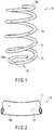
- FIG. 1 shows an example of a coil spring 10 which is coated.
- FIG. 2 shows a part of the coated coil spring 10 (S1 in FIG. 1 ) in an enlarged manner.
- the coil spring 10 includes element wire (wire) 11 formed helically.
- the surface of the wire 11 is covered with a rust-proof coating (paint coat) 12.
- End turn portions 10a and 10b are formed at the ends of the coil spring 10.
- a helically-shaped effective portion 10c is formed between the end turn portions 10a and 10b to deform corresponding to a compressive load applied thereto.
- the lower end turn portion 10a is less than one turn (for example, 0.6 turn) from the lower end of the wire 11.
- the lower end turn portion 10a contacts a lower spring seat.
- the upper end turn portion 10b is less than one turn (for example, 0.6 turn) from the upper end of the wire 11.
- the upper end turn portion 10b contacts an upper spring seat. A torsional stress is produced on the wire 11 when the effective portion 10c is deformed by a compressive load applied on the coil spring 10.
- the coil spring 10 is formed as a cylindrical coil spring.
- the coil spring may be changed in various types such as barrel-type coil spring, hourglass-type coil spring, tapered coil spring, irregularly-pitched coil spring to conform to types of the suspension device.
- the wire 11 is formed of a spring steel of which cross-section is a circle. In a coil spring for a suspension of an automobile, the wire 11 generally has a diameter of 8 to 21 mm; however, the diameter thereof is, of course, optional.
- the spring steel used for the wire 11 is not limited to a specific kind, and there is SAE9254 which complies US "Society of Automotive Engineers", for example. Chemical compositions (mass %) of SAE9254 are C: 0.51 to 0.59, Si: 1.20 to 1.60, Mn: 0.60 to 0.80, Cr: 0.60 to 0.80, S: 0.040 at maximum, P: 0.030 at maximum, Fe: remaining.
- the steel may be a super high strength spring steel.
- FIG. 3 shows the coil spring 10 before coating (formation of a coating film).
- FIG. 4 shows a part of the coil spring 10 before coating (S2 in FIG. 3 ) in an enlarged manner.
- a first rough surface 21 is formed (schematically shown in thicker dots in FIGS. 3 and 4 ).
- the first rough surface 21 includes first shot peening indentations 20.
- the first shot peening indentations 20 include a large number of microscopic asperities.
- first rough surfaces 21 there are several (three or four) first rough surfaces 21 on the lower end turn portion 10a and the upper end turn portion 10b.
- the first rough surfaces 21 are scattered in an island shape at intervals on the end turn portions 10a and 10b in the winding direction thereof.
- the first shot peening indentations 20 are formed on the entire surface of the wire 11 in a first shot peening process explained hereinafter.
- first shots SH1 are projected to a coil spring 12 by, for example, a continuous shot peening device 40 (shown in FIG. 6 ).
- a second rough surface 31 (schematically shown in FIGS. 3 and 4 in thinner dots) is formed on the surface of the wire 11 except for the part where the first rough surface 21 is formed.
- the second rough surface 31 includes second shot peening indentations 30.
- the second shot peening indentations 30 include a large number of microscopic asperities.
- the second shot peening indentations 30 are formed on the entire surface of the wire 11 except for the first rough surface 21 by a vertical motion impeller-type shot peening device 50.
- the vertical motion impeller-type shot peening device 50 will be explained later.
- the surface roughness of the second rough surface 31 is different from that of the first rough surface 21.
- the surface roughness differs depending on the conditions of shot peening.
- the roughness of the second rough surface 31 is less than that of the first rough surface 21.
- the first rough surface 21 has its maximum height of 30 to 50 ⁇ m while the second rough surface 31 has its maximum height of 20 to 30 ⁇ m.
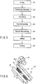
- FIG. 5 shows an example of a manufacturing process of the coil spring 10.
- the wire 11 is formed helically by a coiling machine.
- tempering and annealing of the wire 11 are performed to remove a distortion stress produced in the wire 11 by the forming process S1.
- the wire 11 is heated to 400 to 450 °C and then is cooled slowly.
- hot setting process S3 hot setting is performed in a warm (250 to 350 °C) using a residual heat of the heat treatment process S2.
- a load in the axial direction is applied to the coil spring 10 in the warm for a certain period by a pressure applying device.
- first shot peening is performed in the warm.
- first shots for example, a large size cut wire of which grain diameter is 1.1 mm
- the shot size may vary (for example, between 0.87 and 1.2 mm).
- the first shots are projected to the entire surface of the coil spring 10 in a process temperature of 250 to 300 °C by the continuous shot peening device 40 which is schematically shown in FIG. 6 .
- the speed of projection of the first shots are, for example, 77 m/s.
- FIG. 6 shows an example of the continuous shot peening device 40.
- the shot peening device 40 includes a pair of rotatable rollers 41 and 42 and a centrifugal accelerator (impeller) 43.
- the coil spring 10 disposed on the rollers 41 and 42 is rotated by the rollers 41 and 42 and continuously moves in the direction of arrow F in the figure.
- the centrifugal accelerator (impeller) 43 projects the first shots SH1 to the coil spring 10.
- first shot peening With the first shot peening, a compressive residual stress is produced to a relatively deep position from the surface of the coil spring 10. Furthermore, an oxide film (mill scale formed in the heat treatment) on the surface of the wire 11 is removed by the first shot peening. Furthermore, through the first shot peening, first shot peening indentations 20 (part of which is schematically shown in FIG. 4 ) are formed on the surface of the wire 11. Therefore, in a coating process S7, paint can be easily adhered to the surface of the wire 11 of the coil spring 10 which has been subjected to the first shot peening.
- second shot peening (warm stress shot peening) is performed in a temperature lower than that of the first shot peening process S4 (for example, 200 to 250 °C).
- the second shot peening is performed while the coil spring 10 is compressed by the vertical motion impeller-type shot peening device 50 shown in FIGS. 7 to 10 .
- second shots SH2 (for example, a small size cut wire of which grain diameter is 0.4 to 0.7 mm) is projected to the entire surface of the coil spring 10.
- the size of second shots SH2 are less than that of the first shots SH1 used in the first shot peening process S4.
- the absolute value of the compressive residual stress in the proximity of the surface of wire 11 can be increased. Furthermore, the small size second shots SH2 are projected while the coil spring 10 is heated to the warm temperature range and is compressed. Therefore, the compressive residual stress in the proximity of the surface of coil spring 10 can be increased effectively and the surface roughness of wire 11 can be improved (the surface roughness can be decreased). Therefore, the durability of the coil spring 10 can further be increased.
- a setting process S6 is performed if necessary.
- the length of the coil spring when no load is applied thereto (free length) is adjusted.
- the creep resistance of coil spring (sag resistance) can be improved.
- the setting process S6 may be omitted.
- a coating process S7 a rust-proof paint is applied to the entirety of the coil spring by electrostatic coating or the like. Then, lastly, a quality inspection is performed and the coil spring 10 is completed.
- FIGS. 7 to 10 show the vertical motion impeller-type shot peening device 50.
- the vertical motion impeller-type shot peening device 50 is used in the second shot peening process S5.
- FIG. 7 is a front view showing a part of the vertical motion impeller-type shot peening device 50.
- FIG. 8 is a vertical cross-sectional view, and FIGS. 9 and 10 are horizontal cross-sectional views.
- the vertical motion impeller-type shot peening device 50 includes a housing 51 in which the coil spring (workpiece) 10 is accommodated, workpiece holding mechanism 52, projection mechanism 57, first elevator mechanism 58, and second elevator mechanism 59.
- the workpiece holding mechanism 52 holds the coil spring 10 as standing substantially vertically.
- the projection mechanism 57 includes a first impeller unit 55 and a second impeller unit 56 which project shots SH2 to the coil spring 10.
- the first elevator mechanism 58 moves the first impeller unit 55 vertically.
- the second elevator mechanism 59 moves the second impeller unit 56 vertically.
- the first elevator mechanism 58 and the second elevator mechanism 59 include servo motors 58a and 59a (shown in FIG. 8 ) of which rotation is controlled by a controller and ball screws 58b and 59b rotated by the servo motors 58a and 59a. Based on the direction and amount of rotation of the servo motors 58a and 59a, the impeller units 55 and 56 independently move vertically at constant strokes Y1 and Y2, respectively.
- a first chamber 61, second chamber 62, and middle chambers 63 and 64 which are disposed between the chambers 61 and 62 are formed inside the housing 51.
- a workpiece port 65 is formed in the first chamber 61.
- the workpiece port 65 is an aperture through which the coil spring 10 is put in and out the first chamber 61 from the outside the housing 51.
- the second chamber 62 includes a projection port 55a of the first impeller unit 55 and a projection port 56a of the second impeller unit 56.
- the projection mechanism 57 is structured. Shot SH2 are projected to the coil spring 10 from the projection ports 55a and 56a. That is, the second shot peening is performed by projecting shots SH2 to the coil spring 10 in the second chamber 62.
- partition walls 70 and 71 are provided between the first chamber 61 and the middle chambers 63 and 64.
- Partition walls 72 and 73 are provided between the second chamber 62 and the middle chambers 63 and 64.
- Seal walls 74 and 75 are formed in the middle chambers 63 and 64. The seal walls 74 and 75 keep the shots SH2 projected in the second chamber 62 from going to the first chamber 61.
- the workpiece holding mechanism 52 includes a turntable 79, motor-equipped revolution mechanism 80, and a pair of workpiece holders 81 and 82.
- the turntable 79 rotates around a revolution axis X1 extending in the vertical direction.
- the revolution mechanism 80 intermittently rotates the turntable 79, 180° at a time around the revolution axis X1 in either first direction R1 or second direction R2 (shown in FIG. 9 ).
- the workpiece holders 81 and 82 are disposed on the turntable 79.
- the workpiece holders 81 and 82 each include lower end turn supports 84 and 85 contacting the lower end turn portion 10a of the coil spring 10.
- the workpiece holders 81 and 82 are positioned 180° symmetrically about the revolution axis X1.
- a pair of backup plates 86 and 87 are disposed in the rear side of the workpiece holders 81 and 82.
- the backup plates 86 and 87 receive shots projected to the coil spring 10 in the second chamber 62.
- the lower end turn support 84 provided with the workpiece holder 81 includes a plurality of pawls (for example, four pawls).
- the pawls are disposed on the workpiece holder 81 in its peripheral direction at regular intervals.
- the pawls are formed in either a U-shape or an L-shape to support the end turn portion 10a inserted from the above.
- the lower end turn support 85 provided with the other workpiece holder 82 includes a plurality of pawls (for example, four pawls).
- the pawls are disposed on the workpiece holder 82 in its peripheral direction at regular intervals.
- the pawls are formed in either a U-shape or an L-shape to support the end turn portion 10a inserted from the above.
- the turntable 79 is rotated by the revolution mechanism 80 (shown in FIG. 7 ).
- the revolution mechanism 80 while placing the workpiece holder 81 in the center of the first chamber 61 (workpiece in-out position shown in FIG. 9 ), moves the other workpiece holder 82 in the center of the second chamber 62 (shot peening position).
- the revolution mechanism 80 while moving the workpiece holder 81 in the center of the second chamber 62 (shot peening position), places the other workpiece holder 82 in the center of the first chamber 61 (workpiece in-out position). That is, the revolution mechanism 80 intermittently rotates the turntable 79, 180° at a time around the revolution axis X1 in either first direction R1 or second direction R2 (shown in FIG. 9 ).
- the workpiece holders 81 and 82 of the workpiece holding mechanism 52 are positioned on the turntable 79, 180° symmetrically.
- the pair of workpiece holders 81 and 82 include the lower end turn supports 84 and 85, respectively.
- the turntable 79 is intermittently rotated 180° at a time around the revolution axis X1 by the revolution mechanism 80. That is, the revolution mechanism 80 rotates the turntable 70 about the revolution axis X1 such that the lower end turn supports 84 and 85 reciprocate over the first chamber 61 and the second chamber 62.
- the vertical motion impeller-type shot peening device 50 of the present embodiment includes a stress applying mechanism 90 and a rotation mechanism 100.
- the stress applying mechanism 90 compresses the coil spring 10 held by the workpiece holding mechanism 52.
- the rotation mechanism 100 allows the coil spring 10 held by the workpiece holding mechanism 52 to rotate around the vertical axes (rotation axes) X2 and X3.
- the stress applying mechanism 90 includes presser members 91 and 92 and presser drivers 93 and 94 which are formed of, for example, a fluid cylinder.
- the presser members 91 and 92 are arranged just above the workpiece holders 81 and 82.
- the presser drivers 93 and 94 move the presser members 91 and 92 vertically, respectively.
- Upper end turn supports 95 and 96 are provided with the presser members 91 and 92.
- the upper end turn supports 95 and 96 contact the upper end turn portion 10b of the coil spring 10.
- the upper end turn support 95 is provided with the presser member 91, and for example, the upper end turn support 95 includes a plurality of U-shaped or L-shaped pawls (for example, four pawls) which can support the end turn portion 10b.
- the pawls are disposed on the presser member 91 in its peripheral direction at regular intervals.
- the upper end turn support 96 is provided with the other presser member 92, and for example, the upper end turn support 96 includes a plurality of U-shaped or L-shaped pawls (for example, four pawls) which can support the end turn portion 10b.
- the pawls are disposed on the presser member 92 in its peripheral direction at regular intervals.
- the presser drivers 93 and 94 move the presser members 91 and 92 vertically.
- the presser drivers 93 and 94 compress the coil spring 10 while placing the presser members 91 and 92 at the lower stroke end.
- the presser drivers 93 and 94 release the pressure to the coil spring 10 while placing the presser members 91 and 92 at the upper stroke end. That is, the presser drivers 93 and 94 are configured to move vertically in a stroke to both compress the coil spring 10 and to release the pressure to the coil spring 10.
- the rotation mechanism 100 which rotates the coil spring 10 includes a lower rotator 101 and an upper rotator 102.
- the lower rotator 101 rotates the workpiece holders 81 and 82 around the vertical axes X2 and X3.
- the upper rotator 102 rotate the presser members 91 and 92 around the vertical axes X2 and X3.
- the lower rotator 101 and the upper rotator 102 rotate in synchronization in the same direction at the same revolution by the drivers and timing belts.
- the drivers are, for example, servo motors controlled by a control circuit.
- the projection mechanism 57 projects shots SH2 to the coil spring 10.
- the projection mechanism 57 includes the first impeller unit 55 and the second impeller unit 56 which can move vertically. As shown in FIG. 8 , the first impeller unit 55 projects shots SH2 to the coil spring 10 in the second chamber 62 from a diagonally upward position. Furthermore, the first impeller unit 55 moves vertically by the first elevator mechanism 58.
- the second impeller unit 56 projects shots SH2 to the coil spring 10 in the second chamber 62 from a diagonally downward position. Furthermore, the second impeller unit 56 moves vertically by the second elevator mechanism 59.
- FIGS. 9 and 10 are horizontal cross-sectional views in which the first impeller unit 55 and the second impeller unit 56 viewed from the above.
- the first impeller unit 55 includes an impeller (wing wheel) 111 rotated by a motor 110 and a distributor 112 which supplies shots SH2 in the impeller 111.
- the second impeller unit 56 includes an impeller 116 rotated by a motor 115 and a distributor 117 which supplies shots SH2 in an impeller 116.
- the coil spring 10 is disposed in the second chamber 62. Shots are projected to the coil spring 10 from each of the first impeller unit 55 and the second impeller unit 56. Lines P1 and P2 in FIG. 9 indicate shot projection directions toward the center of the coil spring 10.
- the first impeller unit 55 and the second impeller unit 56 are arranged such that lines P1 and P2 form an angle ⁇ which is less than 180°(for example, 60°). Therefore, the first impeller unit 55 and the second impeller unit 56 can project shots SH2 to the coil spring 10 without interfering each other.
- the first impeller unit 55 is supported such that it can move vertically along a vertical motion guide member 130 provided with the side of housing 51.
- the first impeller unit 55 reciprocates by the first elevator mechanism 58 from a neutral position N1 shown in FIG. 8 to go over an ascend position A1 and a descend position B1.
- the first elevator mechanism 58 includes, for example, drivers such as servo motor 58a and ball screw 58b.
- the first impeller unit 55 can open/close about the first hinge mechanism 131 provided with the housing 51. That is, the first impeller unit 55 can rotate over a close position shown in FIG. 9 and an open position shown in FIG. 10 . Then, the first impeller unit 55 is securely locked while the second chamber 62 is closed (the close position in FIG. 9 ). Furthermore, the first impeller unit 55 can be set in a state where the second chamber 62 is released (the open position in FIG. 10 ) for maintenance purpose or the like.
- the second impeller unit 56 is supported such that it can move vertically by a vertical-motion guide member 140 provided with the side of housing 51.
- the second impeller unit 56 reciprocates by the first elevator mechanism 59 from a neutral position N2 shown in FIG. 8 to go over an ascend position A2 and a descend position B2.
- the second elevator mechanism 59 includes, for example, drivers such as servo motor 59a and ball screw 59b.
- the second impeller unit 56 can open/close about the second hinge mechanism 141 provided with the housing 51. That is, the second impeller unit 56 can rotate over a close position shown in FIG. 9 and an open position shown in FIG. 10 . Then, the second impeller unit 56 is securely locked while the second chamber 62 is closed (the close position in FIG. 9 ). Furthermore, the second impeller unit 56 can be set in a state where the second chamber 62 is released (the open position in FIG. 10 ) for maintenance purpose or the like.
- the first impeller unit 55 and the second impeller unit 56 are moved to the open positions around the hinge mechanism 131 and 141, respectively.
- the second chamber 62 is released and the inside of second chamber 62 can be seen from the outside of housing 51.
- the inside of first impeller unit 55 and the inside of second impeller unit 56 can be seen through the projection ports 55a and 56a. Therefore, the maintenance of the second chamber 62 and the impeller units 55 and 56 can be performed.
- a first coil spring 10 is disposed on the workpiece holder 81 in the first chamber 61.
- the coil spring 10 drawn in the left of FIG. 7 is in a state where a compression load is not applied (free state) and the length of coil spring 10 (free length) is L1.
- first shot peening indentations 20 are formed preliminarily through the first shot peening process S4 (shown in FIG. 5 ).
- the workpiece holder 81 is stopped in the workpiece in-out position in the first chamber 61.
- the coil spring 10 is disposed on an end turn support 84 of the workpiece holder 81.
- the presser member 91 is lowered to the lower stroke end.
- the coil spring 10 is compressed to a length L2 between the lower end turn support 84 and the upper end turn support 95.
- a torsional stress is applied to the coil spring 10.
- the turn table 79 rotates 180°, the coil spring 10 is conveyed in the shot peening position of the second chamber 62 together with the workpiece holder 81.
- the other workpiece holder 82 is moved to the first chamber 61. Therefore, in the first chamber 61, a second coil spring 10 can be disposed on the workpiece holder 82.
- the compressed coil spring 10 is rotated by the rotation mechanism 100.
- the second shot peening is performed to the rotating coil spring 10 by the first impeller unit 55 and the second impeller unit 56 which move vertically.
- the first impeller unit 55 and the second impeller unit 56 move vertically in synchronization.
- the second shots SH2 are projected to the entire surface of wire 11 including the end turn portions 10a and 10b and the effective portion 10c.
- the second shot peening is performed while the coil spring 10 is compressed. That is, the shots SH2 are projected while gaps between adjacent pairs of turn portions of the wire become less than that in the free state. Therefore, if the shots SH2 are projected from a single direction, the shots may miss a part of the coil spring 10. In consideration of this point, a pair of the impeller units 55 and 56 each move vertically, the coil spring 10 rotates, and the shots SH2 are projected to the coil spring 10 from both diagonally upward and downward positions. Therefore, shots can sufficiently hit the entirety of the coil spring 10.
- the second shots SH2 are projected over the first shot peening indentations by the vertical motion impeller-type shot peening device 50. Therefore, the second shots SH2 hit the surface of wire 11 except for the positions contacting the end turn supports 84, 85, 95, and 96. Thereby, the second rough surface 31 is formed on the surface of wire 11 except for the positions contacting the end turn supports 84, 85, 95, and 96.
- the second rough surface 31 includes a large number of second shot peening indentations 30 of which surface roughness is less than that of the first shot peening indentations 20 (shown in FIGS. 3 and 4 ).
- the second shots SH2 do not hit the positions contacting the end turn supports 84, 85, 95, and 96. Therefore, the first rough surface 21 including the first shot peening indentations 20 is scattered on a part of the end turn portions 10a and 10b.
- the turntable 79 rotates 180°. Thereby, the coil spring 10 on the workpiece holder 81 returns to the first chamber 61 from the second chamber 62. At the same time, a second coil spring 10 held by the other workpiece holder 82 is conveyed in the second chamber 62.
- the presser member 91 moves up.
- the coil spring 10 is extracted to the outside of first chamber 61 from the workpiece port 65.
- the second coil spring 10 is conveyed from the first chamber 61 to the second chamber 62.
- the second coil spring 10 is, as with the first coil spring 10, subjected to the second shot peening by the first impeller unit 55 and the second impeller unit 56 in the second chamber 62.
- the entire surface of coil spring 10 only includes the shot peening indentations of the same surface roughness and first rough surfaces 21 scattered in an island shape are not formed. Therefore, as to the coil spring 10 before the coating, whether or not both the first shot peening and the second shot peening are performed can be checked by seeing the first rough surfaces 21 scattered in an island shape are formed on the end turn portions 10a and 10b. That is, whether or not two kinds of shot peenings have been performed can be checked. After the coating of the coil spring, whether or not there is a first rough surface 21 is checked by peeling off either one of the end turn portions 10a and 10b.
- the first rough surface 21 only includes the first shot peening indentations 20. Therefore, the increase of residual stress obtained by the second shot peening indentations 30 cannot be expected in the first rough surface 21.
- the first rough surfaces 21 are scattered in an island shape on the end turn portions 10a and 10b which can hold much stress. Therefore, even if there are first rough surfaces 21 remaining on a part of the coil spring 10, the durability of coil spring 10 is not harmed thereby.
- the vertical motion impeller-type shot peening device 50 of the present embodiment includes the first chamber 61 and the second chamber 62.
- the turntable 79 intermittently rotates 180° at a time and a pair of workpiece holders 81 and 82 are alternatively conveyed in the first chamber 61 and the second chamber 62. Therefore, while an operator handles the coil spring 10 in the first chamber 61, shot peening is performed in the second chamber 62. Therefore, the second shot peening process S5 can be performed efficiently to a plurality of coil springs 10.
- the vertical motion impeller-type shot peening device of the present application can be applied to a coil spring other than suspension coil spring.
- various models, structures, and arrangements of elements used in the vertical motion impeller-type shot peening device such as specific shapes and structures of the housing, workpiece holding mechanism, stress applying mechanism, rotation mechanism, projection mechanism, and elevator mechanism can be changed arbitrarily.
- the coil spring of the present embodiment can be used various purposes other than the vehicle suspension device.
Landscapes
- Engineering & Computer Science (AREA)
- Mechanical Engineering (AREA)
- General Engineering & Computer Science (AREA)
- Springs (AREA)
- Wire Processing (AREA)
- Structures Of Non-Positive Displacement Pumps (AREA)
Abstract
Description
- Present invention described herein relates to a vertical motion impeller-type shot peening device for performing shot peening to a coil spring and a coil spring subjected to shot peening.
- Coil springs are used as, for example, suspension springs of a suspension device of a vehicle. To increase durability of such a coil spring, there is a known technique to impart a compressive residual stress to the proximity of the surface of the coil spring by shot peening.
Patent Literature 1 discloses an example of conventional shot peening devices. A shot peening device projects shots to the coil spring from a centrifugal accelerator (impeller) as the coil spring continuously conveyed. Furthermore, as disclosed in Patent Literature 2, a shot peening method which produces greater compressive residual stress by stress peening is also known. In the stress peening technique, a coil spring is compressed and shot peening is performed while a stress is applied thereto. -
- Patent Literature 1:
JP2002-361558A - Patent Literature 2:
JP2003-117830A - In the continuous shot peening device disclosed in
Patent Literature 1, a coil spring is continuously conveyed in a single direction and shots are projected from a single direction. In such a continuous shot peening device, some improvement is required to produce a greater compressive residual stress on the entire surface of the coil spring. In the stress peeing disclosed in Patent Literature 2, shot peening is performed while the coil spring is compressed; however, in such a compressed spring coil in the stress peening process, gaps between adjacent pairs of turn portions of a wire become narrower than are in a coil spring in a free state. That is, shots projected from a predetermined direction do not easily enter the gaps between adjacent pairs of turn portions of the wire. Shots hit the outer surface side of the coil spring while the inner surface side of the coil spring is partly shadowed by the wire. In the shadows, shots do not hit sufficiently, and the compressive residual stress becomes insufficient and desired durability cannot be achieved. - Therefore, the present invention aims to provide a vertical motion impeller-type shot peening device which can produce a compressive residual stress effective to improve durability of the coil spring and a coil spring subjected to shot peening of the device.
- According to one embodiment, a vertical motion impeller-type shot peening device includes a housing in which a coil spring as a workpiece is accommodated, workpiece holding mechanism, stress applying mechanism, rotation mechanism, projection mechanism, and elevator mechanism. The housing includes a first chamber with a workpiece port through which the coil spring is put in and put out and a second chamber which performs shot peening to the coil spring. The workpiece holding mechanism includes a lower end turn support contacting a lower end turn portion of the coil spring and an upper end turn support contacting an upper end turn portion of the coil spring. The workpiece holding mechanism which holds the coil spring standing between the lower end turn support and the upper end turn support.
- The stress applying mechanism compresses the coil spring conveyed into the second chamber between the lower end turn support and the upper end turn support. The rotation mechanism rotates the coil spring in the second chamber around its vertical axis. The projection mechanism projects shots toward the coil spring while the coil spring in the second chamber is compressed by the stress applying mechanism and rotated by the rotation mechanism. The elevator mechanism moves the projection mechanism vertically while the shots are projected to the coil spring.
- The workpiece holding mechanism may include a turntable and a revolution mechanism. In the turntable, the lower end turn support is disposed. The revolution mechanism rotates the turntable around the revolution axis such that the lower end turn support reciprocates between the first chamber and the second chamber. Furthermore, the workpiece holding mechanism may include a pair of the lower end turn supports. The lower end turn supports may be arranged on the turntable 180° symmetrically with respect to the revolution axis, and the turntable may be rotated 180° at a time by the revolution mechanism.
- Furthermore, the projection mechanism may include a first impeller unit and a second impeller unit. The first impeller unit projects shots from a diagonally upward position of the coil spring in the second chamber and moves vertically with respect to the coil spring. The second impeller unit projects shots from a diagonally downward position of the coil spring and moves vertically with respect to the coil spring.
- Furthermore, the housing may include a first hinge mechanism and a second hinge mechanism. The first hinge mechanism rotatably supports the first impeller unit in either an open position or a close position with respect to the second chamber. The second hinge mechanism rotatably supports the second impeller unit in either an open position or a close position with respect to the second chamber.
- According to an embodiment, a coil spring comprises a helically formed wire and has end turn portions at its ends. The coil spring includes a first rough surface formed on a part of the surface of the end turn portions, and a second rough surface formed on the entire surface of the wire except for the first rough surface. The first rough surface includes first shot peening indentations. The second rough surface includes second shot peening indentations of which surface roughness is different from that of the first rough surface. For example, the first rough surface is scattered in a plurality of locations in an island shape on the end turn portion at intervals in the winding direction.
- With the vertical motion impeller-type shot peening device of the present invention, a compressive residual stress which is effective for the improvement of the durability can be produced on the coil spring. The first rough surface including first shot peening indentations remains in an island shape on the parts of the end turn portion where the end turn supports contact thereto. However, the first rough surface is formed in the end turn portion which can hold much stress, and thus, there is no disadvantage in the durability even if the first rough surface is created. Whether or not there has been two-shot peening including first shot peening and second shot peening can be checked visually by checking if there is a first rough surface before coating the coil spring.
-
-
FIG. 1 is a perspective view of a coil spring of an embodiment. -
FIG. 2 shows a part of the coil spring ofFIG. 1 in an enlarged manner. -
FIG. 3 is a perspective view of the coil spring before coating. -
FIG. 4 shows a part of the before-coating coil spring ofFIG. 3 in an enlarged manner. -
FIG. 5 shows an example of each process in a manufacturing process of the coil spring ofFIG. 1 . -
FIG. 6 is a perspective view schematically showing a continuous shot peening device. -
FIG. 7 is a front view showing a part of a vertical motion impeller-type shot peening device of an embodiment. -
FIG. 8 is a vertical cross-sectional view of the vertical motion impeller-type shot peening device ofFIG. 7 . -
FIG. 9 is a horizontal cross-sectional view of the vertical motion impeller-type shot peening device ofFIG. 7 . -
FIG. 10 is a horizontal cross-sectional view of the vertical motion impeller-type shot peening device ofFIG. 7 in which an impeller unit is moved in an open position. - A coil spring and a vertical motion impeller-type shot peening device of an embodiment will be explained hereinafter with reference to
FIGS. 1 to 10 . -
FIG. 1 shows an example of acoil spring 10 which is coated.FIG. 2 shows a part of the coated coil spring 10 (S1 inFIG. 1 ) in an enlarged manner. Thecoil spring 10 includes element wire (wire) 11 formed helically. The surface of thewire 11 is covered with a rust-proof coating (paint coat) 12.End turn portions coil spring 10. A helically-shapedeffective portion 10c is formed between theend turn portions - In
FIG. 1 , the lowerend turn portion 10a is less than one turn (for example, 0.6 turn) from the lower end of thewire 11. In, for example, a vehicle suspension device, the lowerend turn portion 10a contacts a lower spring seat. InFIG. 1 , the upperend turn portion 10b is less than one turn (for example, 0.6 turn) from the upper end of thewire 11. In, for example, a vehicle suspension device, the upperend turn portion 10b contacts an upper spring seat. A torsional stress is produced on thewire 11 when theeffective portion 10c is deformed by a compressive load applied on thecoil spring 10. - In the example, the
coil spring 10 is formed as a cylindrical coil spring. However, the coil spring may be changed in various types such as barrel-type coil spring, hourglass-type coil spring, tapered coil spring, irregularly-pitched coil spring to conform to types of the suspension device. Thewire 11 is formed of a spring steel of which cross-section is a circle. In a coil spring for a suspension of an automobile, thewire 11 generally has a diameter of 8 to 21 mm; however, the diameter thereof is, of course, optional. - The spring steel used for the
wire 11 is not limited to a specific kind, and there is SAE9254 which complies US "Society of Automotive Engineers", for example. Chemical compositions (mass %) of SAE9254 are C: 0.51 to 0.59, Si: 1.20 to 1.60, Mn: 0.60 to 0.80, Cr: 0.60 to 0.80, S: 0.040 at maximum, P: 0.030 at maximum, Fe: remaining. The steel may be a super high strength spring steel. -
FIG. 3 shows thecoil spring 10 before coating (formation of a coating film).FIG. 4 shows a part of thecoil spring 10 before coating (S2 inFIG. 3 ) in an enlarged manner. As inFIGS. 3 and 4 , on a part of theend turn portions rough surface 21 is formed (schematically shown in thicker dots inFIGS. 3 and 4 ). The firstrough surface 21 includes firstshot peening indentations 20. The firstshot peening indentations 20 include a large number of microscopic asperities. - There are several (three or four) first
rough surfaces 21 on the lowerend turn portion 10a and the upperend turn portion 10b. The firstrough surfaces 21 are scattered in an island shape at intervals on theend turn portions shot peening indentations 20 are formed on the entire surface of thewire 11 in a first shot peening process explained hereinafter. In the first shot peening process, first shots SH1 are projected to acoil spring 12 by, for example, a continuous shot peening device 40 (shown inFIG. 6 ). A second rough surface 31 (schematically shown inFIGS. 3 and 4 in thinner dots) is formed on the surface of thewire 11 except for the part where the firstrough surface 21 is formed. The secondrough surface 31 includes secondshot peening indentations 30. The secondshot peening indentations 30 include a large number of microscopic asperities. - The second
shot peening indentations 30 are formed on the entire surface of thewire 11 except for the firstrough surface 21 by a vertical motion impeller-typeshot peening device 50. The vertical motion impeller-typeshot peening device 50 will be explained later. The surface roughness of the secondrough surface 31 is different from that of the firstrough surface 21. The surface roughness differs depending on the conditions of shot peening. The roughness of the secondrough surface 31 is less than that of the firstrough surface 21. For example, the firstrough surface 21 has its maximum height of 30 to 50 µm while the secondrough surface 31 has its maximum height of 20 to 30 µm. -
FIG. 5 shows an example of a manufacturing process of thecoil spring 10. In a forming process S1 ofFIG. 5 , thewire 11 is formed helically by a coiling machine. In a heat treatment process S2, tempering and annealing of thewire 11 are performed to remove a distortion stress produced in thewire 11 by the forming process S1. For example, in the heat treatment process S2, thewire 11 is heated to 400 to 450 °C and then is cooled slowly. In a hot setting process S3, hot setting is performed in a warm (250 to 350 °C) using a residual heat of the heat treatment process S2. In the hot setting, a load in the axial direction is applied to thecoil spring 10 in the warm for a certain period by a pressure applying device. - Then, in a first shot peening process S4, first shot peening is performed in the warm. In the first shot peening process S4, first shots (for example, a large size cut wire of which grain diameter is 1.1 mm) are used. Note that the shot size may vary (for example, between 0.87 and 1.2 mm). The first shots are projected to the entire surface of the
coil spring 10 in a process temperature of 250 to 300 °C by the continuousshot peening device 40 which is schematically shown inFIG. 6 . The speed of projection of the first shots are, for example, 77 m/s. -
FIG. 6 shows an example of the continuousshot peening device 40. Theshot peening device 40 includes a pair ofrotatable rollers coil spring 10 disposed on therollers rollers coil spring 10. - With the first shot peening, a compressive residual stress is produced to a relatively deep position from the surface of the
coil spring 10. Furthermore, an oxide film (mill scale formed in the heat treatment) on the surface of thewire 11 is removed by the first shot peening. Furthermore, through the first shot peening, first shot peening indentations 20 (part of which is schematically shown inFIG. 4 ) are formed on the surface of thewire 11. Therefore, in a coating process S7, paint can be easily adhered to the surface of thewire 11 of thecoil spring 10 which has been subjected to the first shot peening. - In a second shot peening process S5 of
FIG. 5 , second shot peening (warm stress shot peening) is performed in a temperature lower than that of the first shot peening process S4 (for example, 200 to 250 °C). The second shot peening is performed while thecoil spring 10 is compressed by the vertical motion impeller-typeshot peening device 50 shown inFIGS. 7 to 10 . In the second shot peening process S5, second shots SH2 (for example, a small size cut wire of which grain diameter is 0.4 to 0.7 mm) is projected to the entire surface of thecoil spring 10. The size of second shots SH2 are less than that of the first shots SH1 used in the first shot peening process S4. - Through the second shot peening process S5 (warm stress shot peening), the absolute value of the compressive residual stress in the proximity of the surface of
wire 11 can be increased. Furthermore, the small size second shots SH2 are projected while thecoil spring 10 is heated to the warm temperature range and is compressed. Therefore, the compressive residual stress in the proximity of the surface ofcoil spring 10 can be increased effectively and the surface roughness ofwire 11 can be improved (the surface roughness can be decreased). Therefore, the durability of thecoil spring 10 can further be increased. - After the second shot peening process S5, a setting process S6 is performed if necessary. Through the setting process S6, the length of the coil spring when no load is applied thereto (free length) is adjusted. In the setting process S6, the creep resistance of coil spring (sag resistance) can be improved. Note that the setting process S6 may be omitted. Then, in a coating process S7, a rust-proof paint is applied to the entirety of the coil spring by electrostatic coating or the like. Then, lastly, a quality inspection is performed and the
coil spring 10 is completed. -
FIGS. 7 to 10 show the vertical motion impeller-typeshot peening device 50. The vertical motion impeller-typeshot peening device 50 is used in the second shot peening process S5.FIG. 7 is a front view showing a part of the vertical motion impeller-typeshot peening device 50.FIG. 8 is a vertical cross-sectional view, andFIGS. 9 and10 are horizontal cross-sectional views. - The vertical motion impeller-type
shot peening device 50 includes ahousing 51 in which the coil spring (workpiece) 10 is accommodated,workpiece holding mechanism 52,projection mechanism 57,first elevator mechanism 58, andsecond elevator mechanism 59. Theworkpiece holding mechanism 52 holds thecoil spring 10 as standing substantially vertically. Theprojection mechanism 57 includes afirst impeller unit 55 and asecond impeller unit 56 which project shots SH2 to thecoil spring 10. Thefirst elevator mechanism 58 moves thefirst impeller unit 55 vertically. Thesecond elevator mechanism 59 moves thesecond impeller unit 56 vertically. - For example, the
first elevator mechanism 58 and thesecond elevator mechanism 59 includeservo motors FIG. 8 ) of which rotation is controlled by a controller and ball screws 58b and 59b rotated by theservo motors servo motors impeller units - As shown in
FIGS. 8 and9 , afirst chamber 61,second chamber 62, andmiddle chambers chambers housing 51. Aworkpiece port 65 is formed in thefirst chamber 61. Theworkpiece port 65 is an aperture through which thecoil spring 10 is put in and out thefirst chamber 61 from the outside thehousing 51. - The
second chamber 62 includes aprojection port 55a of thefirst impeller unit 55 and aprojection port 56a of thesecond impeller unit 56. With thefirst impeller unit 55 and thesecond impeller unit 56, theprojection mechanism 57 is structured. Shot SH2 are projected to thecoil spring 10 from theprojection ports coil spring 10 in thesecond chamber 62. - As shown in
FIGS. 9 and10 ,partition walls first chamber 61 and themiddle chambers Partition walls second chamber 62 and themiddle chambers Seal walls middle chambers seal walls second chamber 62 from going to thefirst chamber 61. - As shown in
FIG. 7 , theworkpiece holding mechanism 52 includes aturntable 79, motor-equippedrevolution mechanism 80, and a pair ofworkpiece holders turntable 79 rotates around a revolution axis X1 extending in the vertical direction. Therevolution mechanism 80 intermittently rotates theturntable 79, 180° at a time around the revolution axis X1 in either first direction R1 or second direction R2 (shown inFIG. 9 ). Theworkpiece holders turntable 79. - The
workpiece holders end turn portion 10a of thecoil spring 10. Theworkpiece holders workpiece holders backup plates backup plates coil spring 10 in thesecond chamber 62. - For example, the lower
end turn support 84 provided with theworkpiece holder 81 includes a plurality of pawls (for example, four pawls). The pawls are disposed on theworkpiece holder 81 in its peripheral direction at regular intervals. The pawls are formed in either a U-shape or an L-shape to support theend turn portion 10a inserted from the above. The lowerend turn support 85 provided with theother workpiece holder 82 includes a plurality of pawls (for example, four pawls). The pawls are disposed on theworkpiece holder 82 in its peripheral direction at regular intervals. As with the pawls of theworkpiece holder 81, the pawls are formed in either a U-shape or an L-shape to support theend turn portion 10a inserted from the above. - The
turntable 79 is rotated by the revolution mechanism 80 (shown inFIG. 7 ). Therevolution mechanism 80, while placing theworkpiece holder 81 in the center of the first chamber 61 (workpiece in-out position shown inFIG. 9 ), moves theother workpiece holder 82 in the center of the second chamber 62 (shot peening position). Furthermore, therevolution mechanism 80, while moving theworkpiece holder 81 in the center of the second chamber 62 (shot peening position), places theother workpiece holder 82 in the center of the first chamber 61 (workpiece in-out position). That is, therevolution mechanism 80 intermittently rotates theturntable 79, 180° at a time around the revolution axis X1 in either first direction R1 or second direction R2 (shown inFIG. 9 ). - In the present embodiment, the
workpiece holders workpiece holding mechanism 52 are positioned on theturntable 79, 180° symmetrically. The pair ofworkpiece holders turntable 79 is intermittently rotated 180° at a time around the revolution axis X1 by therevolution mechanism 80. That is, therevolution mechanism 80 rotates theturntable 70 about the revolution axis X1 such that the lower end turn supports 84 and 85 reciprocate over thefirst chamber 61 and thesecond chamber 62. - Furthermore, the vertical motion impeller-type
shot peening device 50 of the present embodiment includes astress applying mechanism 90 and arotation mechanism 100. Thestress applying mechanism 90 compresses thecoil spring 10 held by theworkpiece holding mechanism 52. Therotation mechanism 100 allows thecoil spring 10 held by theworkpiece holding mechanism 52 to rotate around the vertical axes (rotation axes) X2 and X3. - The
stress applying mechanism 90 includespresser members presser drivers presser members workpiece holders presser drivers presser members presser members end turn portion 10b of thecoil spring 10. - The upper
end turn support 95 is provided with thepresser member 91, and for example, the upperend turn support 95 includes a plurality of U-shaped or L-shaped pawls (for example, four pawls) which can support theend turn portion 10b. The pawls are disposed on thepresser member 91 in its peripheral direction at regular intervals. The upperend turn support 96 is provided with theother presser member 92, and for example, the upperend turn support 96 includes a plurality of U-shaped or L-shaped pawls (for example, four pawls) which can support theend turn portion 10b. The pawls are disposed on thepresser member 92 in its peripheral direction at regular intervals. - The
presser drivers presser members presser drivers coil spring 10 while placing thepresser members presser drivers coil spring 10 while placing thepresser members presser drivers coil spring 10 and to release the pressure to thecoil spring 10. - The
rotation mechanism 100 which rotates thecoil spring 10 includes alower rotator 101 and anupper rotator 102. Thelower rotator 101 rotates theworkpiece holders upper rotator 102 rotate thepresser members lower rotator 101 and theupper rotator 102 rotate in synchronization in the same direction at the same revolution by the drivers and timing belts. The drivers are, for example, servo motors controlled by a control circuit. - The
projection mechanism 57 projects shots SH2 to thecoil spring 10. Theprojection mechanism 57 includes thefirst impeller unit 55 and thesecond impeller unit 56 which can move vertically. As shown inFIG. 8 , thefirst impeller unit 55 projects shots SH2 to thecoil spring 10 in thesecond chamber 62 from a diagonally upward position. Furthermore, thefirst impeller unit 55 moves vertically by thefirst elevator mechanism 58. Thesecond impeller unit 56 projects shots SH2 to thecoil spring 10 in thesecond chamber 62 from a diagonally downward position. Furthermore, thesecond impeller unit 56 moves vertically by thesecond elevator mechanism 59. -
FIGS. 9 and10 are horizontal cross-sectional views in which thefirst impeller unit 55 and thesecond impeller unit 56 viewed from the above. Thefirst impeller unit 55 includes an impeller (wing wheel) 111 rotated by amotor 110 and adistributor 112 which supplies shots SH2 in theimpeller 111. Thesecond impeller unit 56 includes animpeller 116 rotated by amotor 115 and adistributor 117 which supplies shots SH2 in animpeller 116. - As shown in
FIG. 9 , as being viewed from the above, thecoil spring 10 is disposed in thesecond chamber 62. Shots are projected to thecoil spring 10 from each of thefirst impeller unit 55 and thesecond impeller unit 56. Lines P1 and P2 inFIG. 9 indicate shot projection directions toward the center of thecoil spring 10. Thefirst impeller unit 55 and thesecond impeller unit 56 are arranged such that lines P1 and P2 form an angle θ which is less than 180°(for example, 60°). Therefore, thefirst impeller unit 55 and thesecond impeller unit 56 can project shots SH2 to thecoil spring 10 without interfering each other. - The
first impeller unit 55 is supported such that it can move vertically along a verticalmotion guide member 130 provided with the side ofhousing 51. Thefirst impeller unit 55 reciprocates by thefirst elevator mechanism 58 from a neutral position N1 shown inFIG. 8 to go over an ascend position A1 and a descend position B1. Thefirst elevator mechanism 58 includes, for example, drivers such asservo motor 58a andball screw 58b. - Furthermore, the
first impeller unit 55 can open/close about thefirst hinge mechanism 131 provided with thehousing 51. That is, thefirst impeller unit 55 can rotate over a close position shown inFIG. 9 and an open position shown inFIG. 10 . Then, thefirst impeller unit 55 is securely locked while thesecond chamber 62 is closed (the close position inFIG. 9 ). Furthermore, thefirst impeller unit 55 can be set in a state where thesecond chamber 62 is released (the open position inFIG. 10 ) for maintenance purpose or the like. - The
second impeller unit 56 is supported such that it can move vertically by a vertical-motion guide member 140 provided with the side ofhousing 51. Thesecond impeller unit 56 reciprocates by thefirst elevator mechanism 59 from a neutral position N2 shown inFIG. 8 to go over an ascend position A2 and a descend position B2. Thesecond elevator mechanism 59 includes, for example, drivers such asservo motor 59a andball screw 59b. - Furthermore, the
second impeller unit 56 can open/close about thesecond hinge mechanism 141 provided with thehousing 51. That is, thesecond impeller unit 56 can rotate over a close position shown inFIG. 9 and an open position shown inFIG. 10 . Then, thesecond impeller unit 56 is securely locked while thesecond chamber 62 is closed (the close position inFIG. 9 ). Furthermore, thesecond impeller unit 56 can be set in a state where thesecond chamber 62 is released (the open position inFIG. 10 ) for maintenance purpose or the like. - As shown in
FIG. 10 , thefirst impeller unit 55 and thesecond impeller unit 56 are moved to the open positions around thehinge mechanism second chamber 62 is released and the inside ofsecond chamber 62 can be seen from the outside ofhousing 51. At the same time, the inside offirst impeller unit 55 and the inside ofsecond impeller unit 56 can be seen through theprojection ports second chamber 62 and theimpeller units - Now, the second shot peening process S5 (as shown in
FIG. 5 ) performed with the vertical motion impeller-typeshot peening device 50 of the present embodiment will be explained. - Initially, a
first coil spring 10 is disposed on theworkpiece holder 81 in thefirst chamber 61. Thecoil spring 10 drawn in the left ofFIG. 7 is in a state where a compression load is not applied (free state) and the length of coil spring 10 (free length) is L1. On the entire surface ofcoil spring 10, firstshot peening indentations 20 are formed preliminarily through the first shot peening process S4 (shown inFIG. 5 ). - The
workpiece holder 81 is stopped in the workpiece in-out position in thefirst chamber 61. Thecoil spring 10 is disposed on anend turn support 84 of theworkpiece holder 81. Then, thepresser member 91 is lowered to the lower stroke end. In that state, thecoil spring 10 is compressed to a length L2 between the lowerend turn support 84 and the upperend turn support 95. Thereby, a torsional stress is applied to thecoil spring 10. Then, the turn table 79 rotates 180°, thecoil spring 10 is conveyed in the shot peening position of thesecond chamber 62 together with theworkpiece holder 81. At the same time, theother workpiece holder 82 is moved to thefirst chamber 61. Therefore, in thefirst chamber 61, asecond coil spring 10 can be disposed on theworkpiece holder 82. - In the
second chamber 62, thecompressed coil spring 10 is rotated by therotation mechanism 100. The second shot peening is performed to therotating coil spring 10 by thefirst impeller unit 55 and thesecond impeller unit 56 which move vertically. In the second shot peening, thefirst impeller unit 55 and thesecond impeller unit 56 move vertically in synchronization. Since thecompressed coil spring 10 rotates, the second shots SH2 are projected to the entire surface ofwire 11 including theend turn portions effective portion 10c. By performing the second shot peening with the stress applied, the compressive residual stress can increase in the proximity of the surface ofcoil spring 12. - In the present embodiment, the second shot peening is performed while the
coil spring 10 is compressed. That is, the shots SH2 are projected while gaps between adjacent pairs of turn portions of the wire become less than that in the free state. Therefore, if the shots SH2 are projected from a single direction, the shots may miss a part of thecoil spring 10. In consideration of this point, a pair of theimpeller units coil spring 10 rotates, and the shots SH2 are projected to thecoil spring 10 from both diagonally upward and downward positions. Therefore, shots can sufficiently hit the entirety of thecoil spring 10. - In the second shot peening, the second shots SH2 are projected over the first shot peening indentations by the vertical motion impeller-type
shot peening device 50. Therefore, the second shots SH2 hit the surface ofwire 11 except for the positions contacting the end turn supports 84, 85, 95, and 96. Thereby, the secondrough surface 31 is formed on the surface ofwire 11 except for the positions contacting the end turn supports 84, 85, 95, and 96. The secondrough surface 31 includes a large number of secondshot peening indentations 30 of which surface roughness is less than that of the first shot peening indentations 20 (shown inFIGS. 3 and 4 ). The second shots SH2 do not hit the positions contacting the end turn supports 84, 85, 95, and 96. Therefore, the firstrough surface 21 including the firstshot peening indentations 20 is scattered on a part of theend turn portions - After the second shot peening is performed in the
second chamber 62, theturntable 79 rotates 180°. Thereby, thecoil spring 10 on theworkpiece holder 81 returns to thefirst chamber 61 from thesecond chamber 62. At the same time, asecond coil spring 10 held by theother workpiece holder 82 is conveyed in thesecond chamber 62. - When the
coil spring 10 on theworkpiece holder 81 returns to thefirst chamber 61 from thesecond chamber 62, thepresser member 91 moves up. Thecoil spring 10 is extracted to the outside offirst chamber 61 from theworkpiece port 65. Thesecond coil spring 10 is conveyed from thefirst chamber 61 to thesecond chamber 62. Thesecond coil spring 10 is, as with thefirst coil spring 10, subjected to the second shot peening by thefirst impeller unit 55 and thesecond impeller unit 56 in thesecond chamber 62. - Here, hypothetically, there is some failure in the manufacturing process of the coil spring of
FIG. 5 , and the first shot peening process S4 or the second shot peening process S5 is not performed. In that case, the entire surface ofcoil spring 10 only includes the shot peening indentations of the same surface roughness and firstrough surfaces 21 scattered in an island shape are not formed. Therefore, as to thecoil spring 10 before the coating, whether or not both the first shot peening and the second shot peening are performed can be checked by seeing the firstrough surfaces 21 scattered in an island shape are formed on theend turn portions rough surface 21 is checked by peeling off either one of theend turn portions - The first
rough surface 21 only includes the firstshot peening indentations 20. Therefore, the increase of residual stress obtained by the secondshot peening indentations 30 cannot be expected in the firstrough surface 21. However, the firstrough surfaces 21 are scattered in an island shape on theend turn portions rough surfaces 21 remaining on a part of thecoil spring 10, the durability ofcoil spring 10 is not harmed thereby. - The vertical motion impeller-type
shot peening device 50 of the present embodiment includes thefirst chamber 61 and thesecond chamber 62. Theturntable 79 intermittently rotates 180° at a time and a pair ofworkpiece holders first chamber 61 and thesecond chamber 62. Therefore, while an operator handles thecoil spring 10 in thefirst chamber 61, shot peening is performed in thesecond chamber 62. Therefore, the second shot peening process S5 can be performed efficiently to a plurality of coil springs 10. - The vertical motion impeller-type shot peening device of the present application can be applied to a coil spring other than suspension coil spring. Furthermore, to achieve the present invention, various models, structures, and arrangements of elements used in the vertical motion impeller-type shot peening device such as specific shapes and structures of the housing, workpiece holding mechanism, stress applying mechanism, rotation mechanism, projection mechanism, and elevator mechanism can be changed arbitrarily. For example, there may be only one workpiece holder including lower end turn supports or may be three or more workpiece holders. Furthermore, the coil spring of the present embodiment can be used various purposes other than the vehicle suspension device.
- 10···coil spring, 10a···lower end turn portion, 10b···upper end turn portion, 11···wire, 12···coating (paint coat), 20···first shot peening indentations, 21···first rough surface, 30···second shot peening indentation, 31···second rough surface, 50···vertical motion impeller-type shot peening device, 51···housing, 52···workpiece holding mechanism, 55···first impeller unit, 56···second impeller unit, 57···projection mechanism, 58···first elevator mechanism, 59···second elevator mechanism, 61···first chamber, 62···second chamber, 65···workpiece port, 79···turntable, 80···revolution mechanism, 81, 82···workpiece holder, 84, 85···lower end turn support, 90···stress applying mechanism, 91, 92···presser member, 95, 96···upper end turn support, 100···rotation mechanism, 131···first hinge mechanism, 132···second hinge mechanism, X1-revolution axis, X2, X3···vertical axis, SH1···first shots, SH2···second shots
Claims (6)
- A vertical motion impeller-type shot peening device, characterized by comprising:a housing (51) in which a coil spring (10) is accommodated, the housing (51) including a first chamber (61) with a workpiece port (65) through which the coil spring (10) is put in and put out and a second chamber (62) which performs shot peening to the coil spring (10);a workpiece holding mechanism (52) including a lower end turn support (84, 85) contacting a lower end turn portion (10a) of the coil spring (10) and an upper end turn support (95, 96) contacting an upper end turn portion (10b) of the coil spring (10), the workpiece holding mechanism (52) which holds the coil spring (10) standing between the lower end turn support (84, 85) and the upper end turn support (95, 96);a stress applying mechanism (90) which compresses the coil spring (10) conveyed into the second chamber (62) between the lower end turn support (84, 85) and the upper end turn support (95, 96);an rotation mechanism (100) which allows the coil spring (10) in the second chamber (62) to rotate around a vertical axis;a projection mechanism (57) which projects shots toward the coil spring (10) while the coil spring (10) in the second chamber (62) is compressed by the stress applying mechanism (90) and rotated by the rotation mechanism (100); anda elevator mechanism (58, 59) which moves the projection mechanism (57) vertically while the shots are projected to the coil spring (10).
- The vertical motion impeller-type shot peening device of claim 1, characterized in that the workpiece holding mechanism (52) includes:a turntable (79) on which the lower end turn support (84, 85) is disposed; anda revolution mechanism (80) which rotates the turntable (79) around a revolution axis (X1) such that the lower end turn support (84, 85) reciprocates between the first chamber (61) and the second chamber (62).
- The vertical motion impeller-type shot peening device of claim 2, characterized in that the workpiece holding mechanism (52) includes a pair of the lower end turn supports (84, 85) which are arranged on the turntable (79) 180° symmetrically with respect to the revolution axis (X1), and the turntable (79) is rotated 180° at a time by the revolution mechanism (80).
- The vertical motion impeller-type shot peening device of any one of claims 1 to 3, characterized in that the projection mechanism (57) includes a first impeller unit (55) which projects shots from a diagonally upward position of the coil spring (10) in the second chamber (62) and moves vertically with respect to the coil spring (10), and a second impeller unit (56) which projects shots from a diagonally downward position of the coil spring (10) and moves vertically with respect to the coil spring (10).
- The vertical motion impeller-type shot peening device of claim 4, characterized in that the housing (51) includes a first hinge mechanism (131) which rotatably supports the first impeller unit (55) in either an open position or a close position with respect to the second chamber (62), and a second hinge mechanism (132) which rotatably supports the second impeller unit (56) in either an open position or a close position with respect to the second chamber (62).
- A coil spring (10) characterized by comprising a helically formed wire (11) and having end turn portions (10a, 10b) at ends thereof, the coil spring comprising:a first rough surface (21) including first shot peening indentations (20) formed on a part of the surface of the end turn portions (10a, 10b); anda second rough surface (31) including second shot peening indentations (30) formed on the entire surface of the wire (11) except for the first rough surface (21), the second rough surface (31) having a surface roughness which is different from that of the first rough surface (21).
Applications Claiming Priority (2)
| Application Number | Priority Date | Filing Date | Title |
|---|---|---|---|
| JP2014167758A JP6318048B2 (en) | 2014-08-20 | 2014-08-20 | Impeller lift peening machine |
| PCT/JP2015/066609 WO2016027554A1 (en) | 2014-08-20 | 2015-06-09 | Vertical motion impeller-type shot peening device and coil spring |
Publications (3)
| Publication Number | Publication Date |
|---|---|
| EP3184242A1 true EP3184242A1 (en) | 2017-06-28 |
| EP3184242A4 EP3184242A4 (en) | 2018-04-18 |
| EP3184242B1 EP3184242B1 (en) | 2022-01-26 |
Family
ID=55350507
Family Applications (1)
| Application Number | Title | Priority Date | Filing Date |
|---|---|---|---|
| EP15834152.9A Active EP3184242B1 (en) | 2014-08-20 | 2015-06-09 | Vertical motion impeller-type shot peening device |
Country Status (8)
| Country | Link |
|---|---|
| US (2) | US10315287B2 (en) |
| EP (1) | EP3184242B1 (en) |
| JP (1) | JP6318048B2 (en) |
| CN (1) | CN107000162B (en) |
| ES (1) | ES2906432T3 (en) |
| HU (1) | HUE058029T2 (en) |
| MX (2) | MX391532B (en) |
| WO (1) | WO2016027554A1 (en) |
Cited By (1)
| Publication number | Priority date | Publication date | Assignee | Title |
|---|---|---|---|---|
| EP3593945A4 (en) * | 2017-06-30 | 2020-12-23 | Sintokogio, Ltd. | RADIATION TREATMENT DEVICE |
Families Citing this family (9)
| Publication number | Priority date | Publication date | Assignee | Title |
|---|---|---|---|---|
| JP6318048B2 (en) * | 2014-08-20 | 2018-04-25 | 日本発條株式会社 | Impeller lift peening machine |
| ES2831838T3 (en) | 2016-02-23 | 2021-06-09 | Nhk Spring Co Ltd | Coil Spring Processing Device |
| JP6554569B2 (en) * | 2018-01-29 | 2019-07-31 | 日本発條株式会社 | Impeller lift type shot peening system |
| WO2019189644A1 (en) | 2018-03-28 | 2019-10-03 | 日本発條株式会社 | Plate spring member |
| CN109158241A (en) * | 2018-10-29 | 2019-01-08 | 南京弹簧有限公司 | A kind of tension spring processing unit (plant) |
| US11306793B2 (en) * | 2019-10-11 | 2022-04-19 | The McAlear Group, Inc. | Torque adjustment mechanism |
| JP7379233B2 (en) * | 2020-03-24 | 2023-11-14 | 日立Astemo株式会社 | Coil spring jig, coil spring manufacturing method, and coil spring testing method |
| JP6935975B1 (en) * | 2020-03-24 | 2021-09-15 | 日立Astemo株式会社 | Manufacturing method of coil spring for suspension system of saddle type vehicle |
| CN115679057B (en) * | 2022-11-16 | 2024-11-26 | 中国航发动力股份有限公司 | Ultrasonic shot peening device for fatigue test rod |
Family Cites Families (27)
| Publication number | Priority date | Publication date | Assignee | Title |
|---|---|---|---|---|
| US3103767A (en) * | 1960-09-06 | 1963-09-17 | Elmer H Greenberg | Metal-plate-treating apparatus |
| US3604157A (en) * | 1969-04-10 | 1971-09-14 | Wheelabrator Corp | Blast machine with automatic blast wheel positioner |
| US3731432A (en) * | 1972-01-05 | 1973-05-08 | Carborundum Co | Apparatus for removing wustite scale centrifugal blasting |
| JPH0531671A (en) * | 1991-07-22 | 1993-02-09 | Chuo Spring Co Ltd | Coil spring peening method |
| DE4408643C1 (en) * | 1994-03-15 | 1995-06-22 | Krupp Ag Hoesch Krupp | Shot-blasting equipment for vehicle compression coil-springs |
| JP2895393B2 (en) * | 1994-05-23 | 1999-05-24 | サンコール株式会社 | Shot peening method for springs with close contact |
| US5879223A (en) * | 1997-06-02 | 1999-03-09 | Aga Ab | Shot blaster with impeller/blower |
| US5823034A (en) * | 1997-10-10 | 1998-10-20 | Hyperform Technologies, Inc. | Superplastic metalforming with self-contained die |
| JP2000345238A (en) | 1999-03-31 | 2000-12-12 | Showa Corp | Manufacturing method of suspension spring for automobile |
| JP4042953B2 (en) | 1999-06-08 | 2008-02-06 | 日本発条株式会社 | Spring for automobile suspension and manufacturing method thereof |
| JP2002361558A (en) | 2001-06-06 | 2002-12-18 | Chuo Spring Co Ltd | Shot peening method for coil spring |
| JP2003117830A (en) * | 2001-10-17 | 2003-04-23 | Nhk Spring Co Ltd | Shot peening equipment |
| US6646904B2 (en) * | 2001-12-21 | 2003-11-11 | Intel Corporation | Ferroelectric memory and method of reading the same |
| US7140216B2 (en) * | 2004-11-18 | 2006-11-28 | General Electric Company | laser aligned shotpeen nozzle |
| US7946009B2 (en) * | 2007-04-17 | 2011-05-24 | Mssc Us | Peening method for vehicle suspension spring |
| KR100931155B1 (en) * | 2008-04-30 | 2009-12-11 | 대원강업주식회사 | Stress Shortening Device for Coil Spring |
| JP5393280B2 (en) * | 2009-06-17 | 2014-01-22 | 日本発條株式会社 | Coil spring for vehicle suspension and manufacturing method thereof |
| JP5393281B2 (en) * | 2009-06-17 | 2014-01-22 | 日本発條株式会社 | Coil spring manufacturing method |
| JP5321978B2 (en) * | 2009-10-07 | 2013-10-23 | 新東工業株式会社 | Continuous conveyor type shot peening apparatus and shot peening method |
| WO2012014542A1 (en) * | 2010-07-27 | 2012-02-02 | 新東工業株式会社 | Shot peening method and shot peening apparatus |
| JP2014176902A (en) * | 2011-07-07 | 2014-09-25 | Sintokogio Ltd | Shot treatment device |
| JP2014176903A (en) * | 2011-07-19 | 2014-09-25 | Sintokogio Ltd | Shot treatment device |
| JP2015077638A (en) * | 2012-02-13 | 2015-04-23 | 新東工業株式会社 | Shot processing device and shot processing method |
| JP5361098B1 (en) | 2012-09-14 | 2013-12-04 | 日本発條株式会社 | Compression coil spring and method of manufacturing the same |
| JP2016540121A (en) * | 2013-11-15 | 2016-12-22 | マサチューセッツ インスティテュート オブ テクノロジー | Method for controlling energy decay of shape memory alloys using surface roughness |
| MX367553B (en) * | 2014-05-28 | 2019-08-27 | Nhk Spring Co Ltd | Suspension spring device and suspension coil spring. |
| JP6318048B2 (en) * | 2014-08-20 | 2018-04-25 | 日本発條株式会社 | Impeller lift peening machine |
-
2014
- 2014-08-20 JP JP2014167758A patent/JP6318048B2/en active Active
-
2015
- 2015-06-09 ES ES15834152T patent/ES2906432T3/en active Active
- 2015-06-09 CN CN201580044337.5A patent/CN107000162B/en active Active
- 2015-06-09 HU HUE15834152A patent/HUE058029T2/en unknown
- 2015-06-09 EP EP15834152.9A patent/EP3184242B1/en active Active
- 2015-06-09 MX MX2017002063A patent/MX391532B/en unknown
- 2015-06-09 WO PCT/JP2015/066609 patent/WO2016027554A1/en not_active Ceased
-
2017
- 2017-02-15 MX MX2021013722A patent/MX2021013722A/en unknown
- 2017-02-16 US US15/434,519 patent/US10315287B2/en active Active
-
2019
- 2019-04-12 US US16/383,231 patent/US10836013B2/en active Active
Cited By (2)
| Publication number | Priority date | Publication date | Assignee | Title |
|---|---|---|---|---|
| EP3593945A4 (en) * | 2017-06-30 | 2020-12-23 | Sintokogio, Ltd. | RADIATION TREATMENT DEVICE |
| US11161220B2 (en) | 2017-06-30 | 2021-11-02 | Sintokogio, Ltd. | Shot treatment device |
Also Published As
| Publication number | Publication date |
|---|---|
| US20190232462A1 (en) | 2019-08-01 |
| CN107000162B (en) | 2019-09-03 |
| WO2016027554A1 (en) | 2016-02-25 |
| MX391532B (en) | 2025-03-19 |
| EP3184242B1 (en) | 2022-01-26 |
| ES2906432T3 (en) | 2022-04-18 |
| MX2021013722A (en) | 2021-12-10 |
| BR112017003396A2 (en) | 2017-11-28 |
| US10836013B2 (en) | 2020-11-17 |
| JP6318048B2 (en) | 2018-04-25 |
| EP3184242A4 (en) | 2018-04-18 |
| JP2016043429A (en) | 2016-04-04 |
| MX2017002063A (en) | 2017-05-25 |
| HUE058029T2 (en) | 2022-06-28 |
| US10315287B2 (en) | 2019-06-11 |
| US20170157744A1 (en) | 2017-06-08 |
| CN107000162A (en) | 2017-08-01 |
Similar Documents
| Publication | Publication Date | Title |
|---|---|---|
| EP3184242B1 (en) | Vertical motion impeller-type shot peening device | |
| EP3278926B1 (en) | Continuous shot peening apparatus and method for coil spring | |
| KR101323168B1 (en) | Torsional severe plastic deformation method for conical tube metals | |
| CN105382073A (en) | Spin forming process and apparatus for manufacturing articles by spin forming | |
| EP2644295B1 (en) | Roller hemming device | |
| US20170165736A1 (en) | Apparatus, system, and method for forming metal parts | |
| EP2662162A1 (en) | Roller hemming device | |
| CN102458767A (en) | Method for manufacturing coil spring | |
| CN106624594B (en) | Deep roll forming | |
| EP3421177B1 (en) | Coil spring processing device | |
| JP6554569B2 (en) | Impeller lift type shot peening system | |
| KR101415868B1 (en) | Banding machine | |
| US20150198351A1 (en) | Multi-shaft bending machine for bending rectangular duct body | |
| JP6582119B2 (en) | Shot peening equipment | |
| JP6503482B2 (en) | Coil spring | |
| BR112017003396B1 (en) | VERTICALLY MOVING IMPULER TYPE SHOT BLASTING DEVICE |
Legal Events
| Date | Code | Title | Description |
|---|---|---|---|
| STAA | Information on the status of an ep patent application or granted ep patent |
Free format text: STATUS: THE INTERNATIONAL PUBLICATION HAS BEEN MADE |
|
| PUAI | Public reference made under article 153(3) epc to a published international application that has entered the european phase |
Free format text: ORIGINAL CODE: 0009012 |
|
| STAA | Information on the status of an ep patent application or granted ep patent |
Free format text: STATUS: REQUEST FOR EXAMINATION WAS MADE |
|
| 17P | Request for examination filed |
Effective date: 20170317 |
|
| AK | Designated contracting states |
Kind code of ref document: A1 Designated state(s): AL AT BE BG CH CY CZ DE DK EE ES FI FR GB GR HR HU IE IS IT LI LT LU LV MC MK MT NL NO PL PT RO RS SE SI SK SM TR |
|
| AX | Request for extension of the european patent |
Extension state: BA ME |
|
| DAV | Request for validation of the european patent (deleted) | ||
| DAX | Request for extension of the european patent (deleted) | ||
| A4 | Supplementary search report drawn up and despatched |
Effective date: 20180316 |
|
| RIC1 | Information provided on ipc code assigned before grant |
Ipc: F16F 1/02 20060101ALI20180312BHEP Ipc: B24C 1/10 20060101AFI20180312BHEP Ipc: B24C 3/24 20060101ALI20180312BHEP |
|
| STAA | Information on the status of an ep patent application or granted ep patent |
Free format text: STATUS: EXAMINATION IS IN PROGRESS |
|
| 17Q | First examination report despatched |
Effective date: 20201105 |
|
| RIC1 | Information provided on ipc code assigned before grant |
Ipc: F16F 1/02 20060101ALN20210630BHEP Ipc: F16F 1/04 20060101ALI20210630BHEP Ipc: B24C 3/24 20060101ALI20210630BHEP Ipc: B24C 1/10 20060101AFI20210630BHEP |
|
| RIC1 | Information provided on ipc code assigned before grant |
Ipc: F16F 1/02 20060101ALN20210721BHEP Ipc: F16F 1/04 20060101ALI20210721BHEP Ipc: B24C 3/24 20060101ALI20210721BHEP Ipc: B24C 1/10 20060101AFI20210721BHEP |
|
| GRAP | Despatch of communication of intention to grant a patent |
Free format text: ORIGINAL CODE: EPIDOSNIGR1 |
|
| STAA | Information on the status of an ep patent application or granted ep patent |
Free format text: STATUS: GRANT OF PATENT IS INTENDED |
|
| RIC1 | Information provided on ipc code assigned before grant |
Ipc: F16F 1/02 20060101ALN20210820BHEP Ipc: F16F 1/04 20060101ALI20210820BHEP Ipc: B24C 3/24 20060101ALI20210820BHEP Ipc: B24C 1/10 20060101AFI20210820BHEP |
|
| INTG | Intention to grant announced |
Effective date: 20210909 |
|
| GRAS | Grant fee paid |
Free format text: ORIGINAL CODE: EPIDOSNIGR3 |
|
| GRAA | (expected) grant |
Free format text: ORIGINAL CODE: 0009210 |
|
| STAA | Information on the status of an ep patent application or granted ep patent |
Free format text: STATUS: THE PATENT HAS BEEN GRANTED |
|
| AK | Designated contracting states |
Kind code of ref document: B1 Designated state(s): AL AT BE BG CH CY CZ DE DK EE ES FI FR GB GR HR HU IE IS IT LI LT LU LV MC MK MT NL NO PL PT RO RS SE SI SK SM TR |
|
| REG | Reference to a national code |
Ref country code: GB Ref legal event code: FG4D |
|
| REG | Reference to a national code |
Ref country code: CH Ref legal event code: EP |
|
| REG | Reference to a national code |
Ref country code: AT Ref legal event code: REF Ref document number: 1464889 Country of ref document: AT Kind code of ref document: T Effective date: 20220215 |
|
| REG | Reference to a national code |
Ref country code: IE Ref legal event code: FG4D |
|
| REG | Reference to a national code |
Ref country code: DE Ref legal event code: R096 Ref document number: 602015076704 Country of ref document: DE |
|
| REG | Reference to a national code |
Ref country code: ES Ref legal event code: FG2A Ref document number: 2906432 Country of ref document: ES Kind code of ref document: T3 Effective date: 20220418 |
|
| REG | Reference to a national code |
Ref country code: LT Ref legal event code: MG9D |
|
| REG | Reference to a national code |
Ref country code: NL Ref legal event code: MP Effective date: 20220126 |
|
| REG | Reference to a national code |
Ref country code: AT Ref legal event code: MK05 Ref document number: 1464889 Country of ref document: AT Kind code of ref document: T Effective date: 20220126 |
|
| REG | Reference to a national code |
Ref country code: HU Ref legal event code: AG4A Ref document number: E058029 Country of ref document: HU |
|
| PG25 | Lapsed in a contracting state [announced via postgrant information from national office to epo] |
Ref country code: NL Free format text: LAPSE BECAUSE OF FAILURE TO SUBMIT A TRANSLATION OF THE DESCRIPTION OR TO PAY THE FEE WITHIN THE PRESCRIBED TIME-LIMIT Effective date: 20220126 |
|
| PG25 | Lapsed in a contracting state [announced via postgrant information from national office to epo] |
Ref country code: SE Free format text: LAPSE BECAUSE OF FAILURE TO SUBMIT A TRANSLATION OF THE DESCRIPTION OR TO PAY THE FEE WITHIN THE PRESCRIBED TIME-LIMIT Effective date: 20220126 Ref country code: RS Free format text: LAPSE BECAUSE OF FAILURE TO SUBMIT A TRANSLATION OF THE DESCRIPTION OR TO PAY THE FEE WITHIN THE PRESCRIBED TIME-LIMIT Effective date: 20220126 Ref country code: PT Free format text: LAPSE BECAUSE OF FAILURE TO SUBMIT A TRANSLATION OF THE DESCRIPTION OR TO PAY THE FEE WITHIN THE PRESCRIBED TIME-LIMIT Effective date: 20220526 Ref country code: NO Free format text: LAPSE BECAUSE OF FAILURE TO SUBMIT A TRANSLATION OF THE DESCRIPTION OR TO PAY THE FEE WITHIN THE PRESCRIBED TIME-LIMIT Effective date: 20220426 Ref country code: LT Free format text: LAPSE BECAUSE OF FAILURE TO SUBMIT A TRANSLATION OF THE DESCRIPTION OR TO PAY THE FEE WITHIN THE PRESCRIBED TIME-LIMIT Effective date: 20220126 Ref country code: HR Free format text: LAPSE BECAUSE OF FAILURE TO SUBMIT A TRANSLATION OF THE DESCRIPTION OR TO PAY THE FEE WITHIN THE PRESCRIBED TIME-LIMIT Effective date: 20220126 Ref country code: BG Free format text: LAPSE BECAUSE OF FAILURE TO SUBMIT A TRANSLATION OF THE DESCRIPTION OR TO PAY THE FEE WITHIN THE PRESCRIBED TIME-LIMIT Effective date: 20220426 |
|
| PG25 | Lapsed in a contracting state [announced via postgrant information from national office to epo] |
Ref country code: PL Free format text: LAPSE BECAUSE OF FAILURE TO SUBMIT A TRANSLATION OF THE DESCRIPTION OR TO PAY THE FEE WITHIN THE PRESCRIBED TIME-LIMIT Effective date: 20220126 Ref country code: LV Free format text: LAPSE BECAUSE OF FAILURE TO SUBMIT A TRANSLATION OF THE DESCRIPTION OR TO PAY THE FEE WITHIN THE PRESCRIBED TIME-LIMIT Effective date: 20220126 Ref country code: GR Free format text: LAPSE BECAUSE OF FAILURE TO SUBMIT A TRANSLATION OF THE DESCRIPTION OR TO PAY THE FEE WITHIN THE PRESCRIBED TIME-LIMIT Effective date: 20220427 Ref country code: FI Free format text: LAPSE BECAUSE OF FAILURE TO SUBMIT A TRANSLATION OF THE DESCRIPTION OR TO PAY THE FEE WITHIN THE PRESCRIBED TIME-LIMIT Effective date: 20220126 Ref country code: AT Free format text: LAPSE BECAUSE OF FAILURE TO SUBMIT A TRANSLATION OF THE DESCRIPTION OR TO PAY THE FEE WITHIN THE PRESCRIBED TIME-LIMIT Effective date: 20220126 |
|
| PG25 | Lapsed in a contracting state [announced via postgrant information from national office to epo] |
Ref country code: IS Free format text: LAPSE BECAUSE OF FAILURE TO SUBMIT A TRANSLATION OF THE DESCRIPTION OR TO PAY THE FEE WITHIN THE PRESCRIBED TIME-LIMIT Effective date: 20220526 |
|
| REG | Reference to a national code |
Ref country code: DE Ref legal event code: R097 Ref document number: 602015076704 Country of ref document: DE |
|
| PG25 | Lapsed in a contracting state [announced via postgrant information from national office to epo] |
Ref country code: SM Free format text: LAPSE BECAUSE OF FAILURE TO SUBMIT A TRANSLATION OF THE DESCRIPTION OR TO PAY THE FEE WITHIN THE PRESCRIBED TIME-LIMIT Effective date: 20220126 Ref country code: SK Free format text: LAPSE BECAUSE OF FAILURE TO SUBMIT A TRANSLATION OF THE DESCRIPTION OR TO PAY THE FEE WITHIN THE PRESCRIBED TIME-LIMIT Effective date: 20220126 Ref country code: RO Free format text: LAPSE BECAUSE OF FAILURE TO SUBMIT A TRANSLATION OF THE DESCRIPTION OR TO PAY THE FEE WITHIN THE PRESCRIBED TIME-LIMIT Effective date: 20220126 Ref country code: EE Free format text: LAPSE BECAUSE OF FAILURE TO SUBMIT A TRANSLATION OF THE DESCRIPTION OR TO PAY THE FEE WITHIN THE PRESCRIBED TIME-LIMIT Effective date: 20220126 Ref country code: DK Free format text: LAPSE BECAUSE OF FAILURE TO SUBMIT A TRANSLATION OF THE DESCRIPTION OR TO PAY THE FEE WITHIN THE PRESCRIBED TIME-LIMIT Effective date: 20220126 Ref country code: CZ Free format text: LAPSE BECAUSE OF FAILURE TO SUBMIT A TRANSLATION OF THE DESCRIPTION OR TO PAY THE FEE WITHIN THE PRESCRIBED TIME-LIMIT Effective date: 20220126 |
|
| PG25 | Lapsed in a contracting state [announced via postgrant information from national office to epo] |
Ref country code: AL Free format text: LAPSE BECAUSE OF FAILURE TO SUBMIT A TRANSLATION OF THE DESCRIPTION OR TO PAY THE FEE WITHIN THE PRESCRIBED TIME-LIMIT Effective date: 20220126 |
|
| PLBE | No opposition filed within time limit |
Free format text: ORIGINAL CODE: 0009261 |
|
| STAA | Information on the status of an ep patent application or granted ep patent |
Free format text: STATUS: NO OPPOSITION FILED WITHIN TIME LIMIT |
|
| 26N | No opposition filed |
Effective date: 20221027 |
|
| PG25 | Lapsed in a contracting state [announced via postgrant information from national office to epo] |
Ref country code: MC Free format text: LAPSE BECAUSE OF FAILURE TO SUBMIT A TRANSLATION OF THE DESCRIPTION OR TO PAY THE FEE WITHIN THE PRESCRIBED TIME-LIMIT Effective date: 20220126 |
|
| REG | Reference to a national code |
Ref country code: CH Ref legal event code: PL |
|
| REG | Reference to a national code |
Ref country code: BE Ref legal event code: MM Effective date: 20220630 |
|
| PG25 | Lapsed in a contracting state [announced via postgrant information from national office to epo] |
Ref country code: SI Free format text: LAPSE BECAUSE OF FAILURE TO SUBMIT A TRANSLATION OF THE DESCRIPTION OR TO PAY THE FEE WITHIN THE PRESCRIBED TIME-LIMIT Effective date: 20220126 |
|
| PG25 | Lapsed in a contracting state [announced via postgrant information from national office to epo] |
Ref country code: LU Free format text: LAPSE BECAUSE OF NON-PAYMENT OF DUE FEES Effective date: 20220609 Ref country code: LI Free format text: LAPSE BECAUSE OF NON-PAYMENT OF DUE FEES Effective date: 20220630 Ref country code: IE Free format text: LAPSE BECAUSE OF NON-PAYMENT OF DUE FEES Effective date: 20220609 Ref country code: CH Free format text: LAPSE BECAUSE OF NON-PAYMENT OF DUE FEES Effective date: 20220630 |
|
| PG25 | Lapsed in a contracting state [announced via postgrant information from national office to epo] |
Ref country code: BE Free format text: LAPSE BECAUSE OF NON-PAYMENT OF DUE FEES Effective date: 20220630 |
|
| PG25 | Lapsed in a contracting state [announced via postgrant information from national office to epo] |
Ref country code: IT Free format text: LAPSE BECAUSE OF FAILURE TO SUBMIT A TRANSLATION OF THE DESCRIPTION OR TO PAY THE FEE WITHIN THE PRESCRIBED TIME-LIMIT Effective date: 20220126 |
|
| PG25 | Lapsed in a contracting state [announced via postgrant information from national office to epo] |
Ref country code: MK Free format text: LAPSE BECAUSE OF FAILURE TO SUBMIT A TRANSLATION OF THE DESCRIPTION OR TO PAY THE FEE WITHIN THE PRESCRIBED TIME-LIMIT Effective date: 20220126 Ref country code: CY Free format text: LAPSE BECAUSE OF FAILURE TO SUBMIT A TRANSLATION OF THE DESCRIPTION OR TO PAY THE FEE WITHIN THE PRESCRIBED TIME-LIMIT Effective date: 20220126 |
|
| PG25 | Lapsed in a contracting state [announced via postgrant information from national office to epo] |
Ref country code: MT Free format text: LAPSE BECAUSE OF FAILURE TO SUBMIT A TRANSLATION OF THE DESCRIPTION OR TO PAY THE FEE WITHIN THE PRESCRIBED TIME-LIMIT Effective date: 20220126 |
|
| PGFP | Annual fee paid to national office [announced via postgrant information from national office to epo] |
Ref country code: DE Payment date: 20250429 Year of fee payment: 11 |
|
| PGFP | Annual fee paid to national office [announced via postgrant information from national office to epo] |
Ref country code: GB Payment date: 20250501 Year of fee payment: 11 |
|
| PGFP | Annual fee paid to national office [announced via postgrant information from national office to epo] |
Ref country code: HU Payment date: 20250529 Year of fee payment: 11 Ref country code: FR Payment date: 20250508 Year of fee payment: 11 |
|
| PGFP | Annual fee paid to national office [announced via postgrant information from national office to epo] |
Ref country code: ES Payment date: 20250701 Year of fee payment: 11 |
|
| PG25 | Lapsed in a contracting state [announced via postgrant information from national office to epo] |
Ref country code: TR Free format text: LAPSE BECAUSE OF FAILURE TO SUBMIT A TRANSLATION OF THE DESCRIPTION OR TO PAY THE FEE WITHIN THE PRESCRIBED TIME-LIMIT Effective date: 20220126 |