EP3183939B1 - High performance electric grill, method, and heat radiating module - Google Patents
High performance electric grill, method, and heat radiating module Download PDFInfo
- Publication number
- EP3183939B1 EP3183939B1 EP15833595.0A EP15833595A EP3183939B1 EP 3183939 B1 EP3183939 B1 EP 3183939B1 EP 15833595 A EP15833595 A EP 15833595A EP 3183939 B1 EP3183939 B1 EP 3183939B1
- Authority
- EP
- European Patent Office
- Prior art keywords
- heating cavity
- emitter plate
- module
- food support
- emitting surface
- Prior art date
- Legal status (The legal status is an assumption and is not a legal conclusion. Google has not performed a legal analysis and makes no representation as to the accuracy of the status listed.)
- Active
Links
Images






Classifications
-
- A—HUMAN NECESSITIES
- A47—FURNITURE; DOMESTIC ARTICLES OR APPLIANCES; COFFEE MILLS; SPICE MILLS; SUCTION CLEANERS IN GENERAL
- A47J—KITCHEN EQUIPMENT; COFFEE MILLS; SPICE MILLS; APPARATUS FOR MAKING BEVERAGES
- A47J37/00—Baking; Roasting; Grilling; Frying
- A47J37/06—Roasters; Grills; Sandwich grills
- A47J37/07—Roasting devices for outdoor use; Barbecues
- A47J37/0704—Roasting devices for outdoor use; Barbecues with horizontal fire box
- A47J37/0709—Roasting devices for outdoor use; Barbecues with horizontal fire box with electric heating elements
-
- A—HUMAN NECESSITIES
- A47—FURNITURE; DOMESTIC ARTICLES OR APPLIANCES; COFFEE MILLS; SPICE MILLS; SUCTION CLEANERS IN GENERAL
- A47J—KITCHEN EQUIPMENT; COFFEE MILLS; SPICE MILLS; APPARATUS FOR MAKING BEVERAGES
- A47J37/00—Baking; Roasting; Grilling; Frying
- A47J37/06—Roasters; Grills; Sandwich grills
- A47J37/0623—Small-size cooking ovens, i.e. defining an at least partially closed cooking cavity
- A47J37/0629—Small-size cooking ovens, i.e. defining an at least partially closed cooking cavity with electric heating elements
-
- F—MECHANICAL ENGINEERING; LIGHTING; HEATING; WEAPONS; BLASTING
- F24—HEATING; RANGES; VENTILATING
- F24C—DOMESTIC STOVES OR RANGES ; DETAILS OF DOMESTIC STOVES OR RANGES, OF GENERAL APPLICATION
- F24C7/00—Stoves or ranges heated by electric energy
- F24C7/04—Stoves or ranges heated by electric energy with heat radiated directly from the heating element
- F24C7/046—Ranges
-
- F—MECHANICAL ENGINEERING; LIGHTING; HEATING; WEAPONS; BLASTING
- F24—HEATING; RANGES; VENTILATING
- F24C—DOMESTIC STOVES OR RANGES ; DETAILS OF DOMESTIC STOVES OR RANGES, OF GENERAL APPLICATION
- F24C7/00—Stoves or ranges heated by electric energy
- F24C7/08—Arrangement or mounting of control or safety devices
- F24C7/087—Arrangement or mounting of control or safety devices of electric circuits regulating heat
-
- F—MECHANICAL ENGINEERING; LIGHTING; HEATING; WEAPONS; BLASTING
- F24—HEATING; RANGES; VENTILATING
- F24C—DOMESTIC STOVES OR RANGES ; DETAILS OF DOMESTIC STOVES OR RANGES, OF GENERAL APPLICATION
- F24C7/00—Stoves or ranges heated by electric energy
- F24C7/10—Stoves or ranges heated by electric energy with special adaptation for travelling, e.g. collapsible
-
- H—ELECTRICITY
- H05—ELECTRIC TECHNIQUES NOT OTHERWISE PROVIDED FOR
- H05B—ELECTRIC HEATING; ELECTRIC LIGHT SOURCES NOT OTHERWISE PROVIDED FOR; CIRCUIT ARRANGEMENTS FOR ELECTRIC LIGHT SOURCES, IN GENERAL
- H05B3/00—Ohmic-resistance heating
- H05B3/20—Heating elements having extended surface area substantially in a two-dimensional [2D] plane, e.g. plate-heater
- H05B3/22—Heating elements having extended surface area substantially in a two-dimensional [2D] plane, e.g. plate-heater non-flexible
- H05B3/26—Heating elements having extended surface area substantially in a two-dimensional [2D] plane, e.g. plate-heater non-flexible heating conductor mounted on insulating base
- H05B3/262—Heating elements having extended surface area substantially in a two-dimensional [2D] plane, e.g. plate-heater non-flexible heating conductor mounted on insulating base the insulating base being an insulated metal plate
-
- H—ELECTRICITY
- H05—ELECTRIC TECHNIQUES NOT OTHERWISE PROVIDED FOR
- H05B—ELECTRIC HEATING; ELECTRIC LIGHT SOURCES NOT OTHERWISE PROVIDED FOR; CIRCUIT ARRANGEMENTS FOR ELECTRIC LIGHT SOURCES, IN GENERAL
- H05B2203/00—Aspects relating to Ohmic resistive heating covered by group H05B3/00
- H05B2203/014—Heaters using resistive wires or cables not provided for in H05B3/54
-
- H—ELECTRICITY
- H05—ELECTRIC TECHNIQUES NOT OTHERWISE PROVIDED FOR
- H05B—ELECTRIC HEATING; ELECTRIC LIGHT SOURCES NOT OTHERWISE PROVIDED FOR; CIRCUIT ARRANGEMENTS FOR ELECTRIC LIGHT SOURCES, IN GENERAL
- H05B2203/00—Aspects relating to Ohmic resistive heating covered by group H05B3/00
- H05B2203/032—Heaters specially adapted for heating by radiation heating
Definitions
- the present invention relates to electric grilling apparatuses and methods, and to an electric module for radiating heat energy for cooking food in an outdoor grill.
- the present invention also relates to infrared cooking grate assemblies.
- WO-A-00/01286 discloses a cooking apparatus having a body defining a chamber and a heating assembly mounted within the chamber.
- the heating assembly includes a burner and an infrared radiant energy emitter positioned above burner.
- the emitter absorbs energy from the burner and emits infrared radiant energy.
- the infrared radiant energy is directed at and is used to cook food supported on a cooking grid above the infrared radiant energy emitter.
- the current electrical outdoor grilling appliance art includes various types of products.
- an electrical resistance heating element is embedded in a cooking grate.
- the electrical element transfers heat by conduction to the grate, which is usually made of a conductive material such as aluminum.
- the grate heats the food by conduction.
- open slots are provided in the grate for draining grease.
- this first type of electric grill suffers from the problem that the temperature of the heated cooking surface must be held below the ignition point of the grease so that fire will not occur at the point of cooking.
- the required low temperature will not sufficiently vaporize the grease to produce the smoke necessary for flavoring the meat when grilling.
- the required low temperature allows accumulated grease to gather on the surface of the cooking grate around the food, despite the provision of grease drainage features.
- a radiant heating element is suspended below an open wire-type cooking grate and is surrounded by an insulating material. Food is cooked by radiant heat through the open grate and by some conduction from the cooking grate, which is heated by the radiant element.
- the conductive heat from the grate can produce, under favorable circumstances, a pattern of "sear" marks desired for grilling.
- This type of grill is generally described in U.S. Patent 6,104,004 .
- a radiant element is used to heat a specific type of grate.
- the grate (a) restricts convective heat, (b) delivers predominately infrared heat to the food supported on it, and (b) uses conductive heat to create a pattern of sear marks on the food.
- a single or double conical heat shield is placed below the heating element to minimize heat loss.
- this third type of grill though presenting better performance, takes a long time to warm up to a sufficient operating temperature for prompt searing.
- a significant amount of free convective flow continuously occurs past the radiant heating element, thus having the effect of cooling the radiant element.
- each of the prior art electric grills described above also suffers from a lack of power density. This condition is driven by the wattage limitations of standard US residential electrical systems. A standard 120 volt current, as limited by a 15 amp circuit breaker, provides an absolute upper power limit of only 1800 watts.
- This power limit produces a thermal energy equivalent of just 6,147 BTU/hr for an entire cooking surface. Consequently, in the case of a 200 square inch cooking surface, the maximum power density available is only 30.7 BTU/hr/in 2 . This power density is much lower than the 100 BTU/hr/in 2 maximum provided by a typical gas grill and is also much lower than the 60 to 80 BTU/hr/in 2 maximum provided by some newer gas infrared cooking systems. As a result, in less than ideal conditions, such as a cold windy day, the electrical cooking appliance may not produce adequate cooking results.
- the present invention is directed to a module for radiating heat energy for cooking food and an outdoor cooking grill for grilling a food product with the features of claims 1 and 8.
- the present invention provides (a) an electric grill, (b) a grilling method, (c) a removable, or built-in, electrically-powered heat radiating module for a grill, and (d) an infrared cooking grate assembly which satisfy the needs and alleviate the problems discussed above.
- the inventive electric grill, method and heat radiating module (a) provide much higher efficiency, a much greater cooking heat flux, and a much greater high cooking temperature than are provided by the prior art electric grills; (b) provide more than 70% infrared cooking energy; (c) provide much higher cooking grate surface temperatures for producing sear marks, even when cooking with the lid open; (d) reduce warm-up times to an extent that an average grate temperature of 450° or more can be achieved in just 15 minutes; and (e) provide these higher cooking and searing temperatures and heat fluxes while at the same reducing flare-ups and significantly increasing the production of beneficial smoke for flavoring.
- the electrically-powered heat radiating module is a separately serviceable part in which the electric heating element is isolated or substantially isolated from contact with drippings containing fat, water, and food particles which are produced in the cooking process.
- a module for radiating heat energy for cooking food comprising: a module housing having a heating cavity therein, the heating cavity having a bottom wall; an emitter plate on or in an upper end portion of the module housing, the emitter plate having an upper emitting surface; and at least one electric heating element positioned in the heating cavity beneath the emitter plate.
- the emitter plate covers and closes an upper end of the heating cavity such that the upper end of said heating cavity is at least 95% closed to air flow out of or into the upper end of the heating cavity.
- the emitter plate and the module housing are at least 95% closed to flow from the upper emitting surface of the emitter plate into the heating cavity of fat and water which fall onto the upper emitting surface from the food.
- the upper emitting surface of the emitter plate comprise an alternating series of ridges and valleys.
- an outdoor cooking grill comprising: a grill base housing having an interior cavity with an interior bottom; a lid for opening and closing the grill base housing; an interior housing at least partially within the interior cavity of the grill base housing above the interior bottom of the interior cavity, the interior housing having a heating cavity therein with a heating cavity bottom wall; an emitter plate positioned on or in an upper end portion of the interior housing, the emitter plate having an upper emitting surface; a food support grate which is positionable on the emitter plate, the food support grate having a food support surface which is spaced above the upper emitting surface of the emitter plate; and at least one electric heating element positioned in the heating cavity beneath the emitter plate.
- the emitter plate covers and closes an upper end of the heating cavity such that the upper end of the heating cavity is at least 95% closed to air flow out of or into the upper end of the heating cavity.
- the emitter plate and the interior housing are at least 95% closed to flow from the upper emitting surface of the emitter plate into the heating cavity of fat and water which fall onto the upper emitting surface from the food product.
- FIGS. 1-3 An embodiment 2 of an outdoor electric grill provided by the present invention is shown in FIGS. 1-3 .
- the inventive electric grill 2 preferably comprises: a base housing 4; a support frame, housing, or other support structure 6 upon which the base housing 4 is mounted; a lid 8 which is pivotably attached to the base housing 4 or is otherwise provided for opening and closing the top of the base housing 4; an inventive electrically-powered heat radiating module 10 which is positioned within or at least partially within the upper portion 12 of the base housing 4; a food support grate 14 which is positioned on the heat radiating module 10; a drip pan or cup 16 in or beneath the base housing 4; and an exterior control panel 18 extending from the base housing 4.
- the inventive module 10 comprises: a module housing 20 having a heating cavity 22 therein; an emitter plate 24 on or in an upper portion 26 of the module housing 20; at least one electric heating element 28 positioned in the heating cavity 22 beneath the emitter plate 24; and electrical power leads 30 which preferably extend through the upwardly extending interior and exterior side walls 32 and 34 of the module housing 20.
- the electric heating element 28 used in the heat radiating module 10 can be generally any type of electrical heating element which will radiate heat when current is applied.
- the electric heating element 28 will preferably be a tubular-type electric resistive heater.
- Tubular-type electric resistive heaters typically comprise a resistive metal wire which is mounted inside a metal tube filled with an electrically resistive but thermally conductive material such as, e.g., magnesium oxide.
- an electrical current is applied to the metal wire, the outer metal tube, or sheath, will typically be heated to a temperature of up to as much as 1,000° to 1,200°F or more.
- the electric heating element 28 could be, for example, a high intensity infrared lamp element or an open ribbon resistive heater.
- the elements 28 can be separately controlled or can be operable such that any ratio of the power supply to the unit can be transmitted to the elements 28, so long as the total power consumed does not exceed, for example, the standard 1800 watt limit provided by electrical outlets in the U.S. or the standard 1500 watt limit provided by electrical outlets in Canada.
- the elements 28 could also be controlled to allow all of the power to be switched to one of the elements 28.
- the housing 20 of the inventive heat radiating module 10 comprises: a heating cavity bottom wall 36 beneath the heating element(s) 28; an inner side wall 32 which extends upwardly from the perimeter of the heating cavity bottom wall 36 and laterally surrounds the heating cavity 22; an exterior bottom wall 38 of the module housing 20 which is outside of and spaced apart from the heating cavity bottom wall 36; a bottom gap 40 defined between the heating cavity bottom wall 36 and the exterior bottom wall 38 of the module housing 20; at least one layer of insulating material 42 provided in the bottom gap 40 beneath the heating cavity 22; an exterior side wall 34 of the housing 20 which extends upwardly from the perimeter of the exterior bottom wall 38 and laterally surrounds the inner side wall 32; an upwardly extending gap 44 defined between the inner side wall 32 and the exterior side wall 34; at least one layer of insulating material 46 which is provided in the upwardly extending gap 44 such that the insulating layer 46 laterally surrounds the heating cavity 22; and at least one infrared reflective radiation barrier surface 48 provided in the heating cavity 22 beneath the heating element(s) 28.
- the reflective radiation barrier surface 48 can be the upper surface of the heating cavity bottom wall 36 or can be the upper surface of another wall within the heating cavity 22 positioned on or above the heating cavity bottom wall 36.
- each electric element 28 When each electric element 28 is heated, it transmits radiant heat energy in both an upward direction and a downward direction. Typically, in most prior art electric grills, the radiant heat energy transmitted from bottom side of the element is mostly lost.
- the radiant energy transmitted from the bottom side of the electric heating element 28 is reflected upwardly by the radiation barrier surface 48 to the emitter plate 24 for (a) cooking the food more efficiently, (b) assisting in reducing the warmup time of the inventive grill 2, and (c) achieving higher cooking and searing temperatures.
- the radiation barrier surface 48 can be formed of any temperature resistant infrared reflective material which is effective for achieving these results.
- the radiation barrier surface 48 is preferably formed of reflective aluminum or stainless steel in single or multiple layers.
- the exterior bottom of the heating cavity 22 is covered, as indicated above, by the layer of insulating material 42 provided in the bottom gap 40.
- the heating cavity 22 is also surrounded laterally by the above-mentioned layer of insulating material 46 which is provided in the upwardly extending gap 44.
- the insulating layers 42 and 46 can be formed of any insulating material suitable for use at temperatures of as much as 1500° F or more and will preferably be formed of non-flammable cotton or fiber glass.
- the lid 8 of the inventive grill 2 can also optionally include heat reflective and/or insulating surfaces or materials in order to further decrease warm up time, and increase overall efficiency.
- examples of such features which can be used in the lid 8 are provided in US Patent No. 6,104,004 .
- the emitter plate 24 of the inventive heat radiating module 10 has an upper emitting surface 50.
- the upper emitting surface 50 has ridges and valleys provided thereon.
- the upper emitting surface 50 comprises an alternating series of ridges 52 and valleys 54.
- the emitter plate 24 shown in FIGS. 3-9 can be preferably stamped, cast or molded, or otherwise produced from a sheet of material so that corresponding ridges and valleys are also formed on the bottom side 56 of the emitter plate 24.
- the flat emitter plate 224 shown in FIGS. 12 and 13 can also be cast, molded, etc., or can be formed, for example, of ceramic glass or a metallic plate.
- the inventive heat radiating module 10, 110, 210, 310 (or just the emitter plate 24, 124, 224, 324 and the cooking grate 14, 114, 214, 314 thereof) can be mounted with a downward slope front to back to speed up grease drainage and thus help keep the plate 24, 124, 224, 324 clean so that less maintenance is required by the consumer and, during the cooking cycle, a dry surface is provided to help produce and emit more radiation energy to the food.
- the ridges 52 of the emitter plate 24 shown in FIGS. 3-9 as well as the ridges of the emitter plates 124 and 324 illustrated in FIGS. 11 and 14-15 will preferably have either (a) an inverted V shape with a peak 58 which can be sharp or rounded or (b) an angled lower portion which is combined with an upper peak portion having more of an inverted U shape.
- the valleys 54 of the emitter plate 24 (as well as those of the emitter plates 124 and 324) will preferably have bottoms 60 which are sharply angled, rounded, or U-shaped.
- Each of the ridges 52 of the emitter plate 24, and of the emitter plates 124 and 324 of FIGS. 11 and 14-15 will preferably have a height in the range of from about 0.125 to about 0.375 inches and a base width in the range of from about 0.25 to about 0.5 inches.
- the upper emitting surface 50 of the emitter plate 24, as well as the upper emitting surfaces of the emitter plates 124, 224, and 324 shown in FIGS 11-15 , will preferably be formed of a suitable high temperature material or coating which has an emissivity of at least 0.4 and which more preferably has an emissivity in the range of from about 0.5 to about 0.9.
- suitable materials for forming the emitter plate 24 include, but are not limited to, porcelain-coated steel, titanium, stainless steel, and aluminized or galvanized steel.
- the emitter plate 24 will preferably be formed of porcelain-coated steel or 304 stainless steel.
- the food support grate 14 shown in FIGS 3-5 and 8-9 comprises a plurality of side-by-side food support ribs 65 having gaps 66 therebetween.
- the ribs 65 are solid structures which, in cross section, have a partial, inverted V shape.
- the ribs 65 have upper surfaces 68 which together form a food support surface 70 which is spaced above the upper emitting surface 50 of the emitter plate 24.
- the ribs 65 also have bottom portions 72 which are positioned in the valleys 54 of the emitter plate 24 such that shielded flow channels 74 for the fat and water which falls onto the emitter plate 24 during the cooking process are defined in the valleys 54 beneath the bottom portions 72 of the ribs 65.
- the food support ribs 114 and 314 used in FIGS. 11 and 14-15 have a hollow, inverted U shape. However, the ribs 114 and 314 also operate to form shielded flow channels beneath the ribs 114 and 314.
- the food support ribs used in any of the embodiments of the present invention can alternatively have a rectangular shape, a sharp or rounded inverted V shape, or generally any other shaped desired.
- the ribs 65, 122, 222, 322 can be solid structures as illustrated in FIGS. 4 and 5 , at least partially hollow structures, or hollow structures as illustrated in FIGS. 11-15 .
- the bottoms 125, 225, 325 of the hollow or partially hollow ribs 122, 222, 322 can be open as shown in FIGS. 11-15 , or closed.
- the upper surfaces 68, 126, 226, 326 of the food support ribs 65, 122, 222, 322 can be flat surfaces as illustrated in FIGS.
- the food support grate 14, 114, 214, 314 will preferably be formed of high temperature porcelain coated steel, stainless steel, hard anodized aluminum, or titanium.
- the height of the food support ribs used in the prior art electric grills have typically been 0.75 inch or more.
- Tall ribs of this height have been necessary in order to sufficiently reduce the amount of oxygen available for combustion at the bottom of the gaps between the ribs.
- these tall ribs have also further reduced the efficiency of the prior art grills.
- the shielded flow channels 74 created beneath the food support ribs operate to reduce the amount of oxygen available to the fat which flows into and through the flow channels 74 to such a degree that, even at the higher operating temperatures which are provided by the inventive grill 2, the inventive grill 2 will still be highly flare-up resistant at a much shorter, and more efficient, rib height of 0.5 inch or less. Consequently, although taller food support ribs can also be used, and may be desirable for example when using an alternative flat emitter plate 224 as illustrated in FIGS. 12 and 13 , the food support ribs of the food support grate 14, 114, 314 will preferably have a height in the range of from about 0.25 to about 0.5 inches and a bottom width in the range of from about 0.25 to about 0.4 inches.
- the shielded flow channels 74 formed by the emitter plate 24 124, 324 and the food support grate 14, 114, 314 of the inventive grill 2 also (a) cause a greater amount of vaporization and smoke generation to occur for flavoring the food and (b) prevent the emitter plate 24, 124, 324 from being cooled by the liquid fat when operating at lower settings below the vaporization point.
- the food support grate 14, 114, 214, 314 of the inventive grill 2 will preferably be removably positionable on the upper emitting surface 50, 150, 250, 350 of the emitter plate 24, 124, 224, 324.
- the emitter plate 24, 124, 224, 324 can be permanently attached to the top of the housing 20, 120, 220, 320 of the inventive heat radiating module 10, 110, 210, 310, the emitter plate will preferably be removably positionable on the housing for ease of maintenance and replacement of the electric heating element(s) 28 and to better accommodate the thermal expansion of the housing components which can occur during operation.
- corrugated ridges 80 or other shapes corresponding to the ridges 52 and valleys 54 of the emitter plate 24 are provided in the upper ends of the upwardly extending inner side wall 32, exterior side wall 34, and insulating layer 46 of the module housing 20 for placement of the emitter plate 24 on the housing 20.
- the upper end 82 of the inner side wall 32 defines the outer perimeter of the upper end 84 of the heating cavity 22.
- the upper end 86 of the exterior side wall 34 defines the outer perimeter of the upper end 83 of the module housing 20.
- the liquefied fat and water which drips onto the emitter plate 24 from the food product quickly enters the flow channels 74 beneath the ribs 65 through gaps 85 existing between the bottom contacting edges 88 of the ribs 65 and the valley walls 90 of the upper emitting surface 50 of the emitter plate 24.
- gaps 85 exist as a natural consequence of the fact that the stamping, casting, shearing, bending, and/or other procedures used for forming the components of the heat radiating module 10 and the food support grate 14 do not provide a precise, theoretical line to line contact between the food support ribs 65 and the emitter plate 24. Consequently, the low viscosity of the hot liquefied fat allows it to flow quite readily through the small gaps 85 and into the flow channels 74.
- the valleys 54 of the upper emitting surface 50 of the emitter plate 24 extend at least as far as, and more preferably beyond, the outer perimeter 86 of the upper end 83 of the module housing 20 so that the liquefied fat and water from the food product falls from the outer ends of the valleys 54 into the interior cavity 92 of the grill base housing 4 outside of the housing 20 of the inventive heat radiating module 10.
- the outer perimeter of the emitter plate will preferably extend at least as far as, and more preferably beyond, the outer perimeter of the upper end of the module housing.
- the emitter plate 24 or the valleys 54 thereof can be oriented, formed, or configured at a slight angle as mentioned above to facilitate and/or accelerate the flow of the liquefied fat and water off of the emitter plate 24.
- the volume of the heating cavity 22 of the module is preferably significantly smaller than the firebox cavity volumes heretofore used in prior art electric grills for holding the electric heating element.
- the volume of the heating cavity 22 below the emitter plate 24 will preferably not be more than (3 x A) in 3 and will more preferably not be more than (1.5 x A) in 3 .
- the volume of the heating cavity 22 will not be greater than A in 3 .
- This much smaller volume of the heating cavity 22 beneath the emitter plate 24 (a) further increases the reflection and recovery of the radiant energy which is emitted downwardly from the heating element(s) 28 or which is otherwise directed toward the bottom of the heating cavity 22 and (b) reduces the volume of air in the cavity 22 which must be heated and maintained at operating temperature.
- the reduced depth of the heating cavity 22 produces an appealing thinner profile for the inventive grill 2 and reduces material costs.
- the dimensions of the smaller heating cavity 22 of the inventive heat radiating module will be such that: (a) the vertical distance from the bottom wall 36 of the heating cavity 22 to the center of the emitter plate 24 will be in the range of from about 1.0 to about 3.0 inches and will more preferably be about 1.5 inches; (b) the vertical distance from the bottom wall 36 of the heating cavity 22 to the outer edge portion of the emitter plate 24 will be in the range of from about 0.5 to about 1.0 inches and will more preferably be about 0.5 inches; (c) the electric heating element(s) 28, which will typically have a diameter of about 0.3 inches, is/are in close proximity to or touching the emitter plate 24; (d) the vertical distance from the heating element(s) 28 to the center of the radiation surface barrier 48 will be in the range of from about 0.7 to about 2.7 inches and will more preferably be about 1.2 inches; and (e) the vertical distance from the heating element(s) 28 to the outer edge portion of the radiation surface barrier 48 will be in the range of from about 0.2 to about 0.7
- the emitter plate 24, 124, 224, 324 of the inventive heat radiating module covers and closes the upper end 84 of the heating cavity 22 such that the upper end 84 of the heating cavity 22 is at least 95% closed, more preferably at least 99% closed, to air flow into or out of the heating cavity 22 through the upper end 84 of the cavity 22.
- the housing 20, 120, 220, 320 of the inventive heat radiating module 10, 110, 210, 310 is preferably at least 95% closed, more preferably at least 99%, closed, to air flow into or out of the heating cavity 22.
- the substantial closure of the heating cavity 22 as described above reduces convective heat transfer to the food product and increases the percentage of total heat flux from infrared radiation at 3mm above the food contacting surface 70 to more than 70% and more preferably at least 72%. Measurements taken during actual tests of the inventive grill 2 and module 10 of FIGS. 1-9 indicated that infrared radiant energy accounted for 74.97% of the total heat flux.
- the emitter plate 24, 124, 224, 324 and the module housing 20, 120, 220, 320 are also preferably at least 95% closed, more preferably at least 99% closed, to any flow of fat and water from the upper emitting surface 50, 150, 250, 350 of the emitter plate 24 into the heating cavity 22.
- the inventive electrically-powered heat radiating module 10, 110, 210, 310 is entirely closed to the flow of fat and water from the food into the heating cavity 22.
- Preventing the flow or leakage of fat and water into the inventive heat radiating module (a) preserves, protects, and extends the life of the electric heating element(s) 28 and the bottom and side insulating materials 42 and 46, (b) prevents fouling of the radiation barrier surface 48 in the bottom of the heating cavity 22 so that the effectiveness of the radiation barrier surface 48 for reflecting radiant energy upwardly toward the emitter plate 24, 124, 224, 324 is preserved, and (c) prevents flare-ups and burning fat with resultant black smoke.
- preventing the flow of fat from the food into the heating cavity 22 eliminates the need for a drainage opening in the bottom of the module housing 10, 110, 210, 310 which would also permit cold air to flow into the heating cavity 22.
- the inventive grill 2 and module 10, 110, 210, 310 will provide an average heat flux of at least 7.5 kW, more preferably at least 8.0 or at least 8.5 kW, per square meter of cooking area on the cooking surface 70 at the highest cooking setting of the inventive heat radiating module 10, 110, 210, 310 when the lid 8 of the grill 2 is closed and the heat radiating module is connected to a standard 120 volt, 1800 watt electrical outlet.
- the inventive grill 2 produced an average heat flux of 9.897 kW/m 2 across the cooking surface versus a heat flux of 5.318 kW/m 2 for the prior art grill, an improvement of 86%.
- the inventive electric grill 2 reached an average grate temperature of 464° F in just 15 minutes whereas the average grate temperature of the prior art electric grill after 15 minutes was only 153° F.
- the inventive grill 2 is capable of achieving an ultimate high temperature at the cooking grate 14, 110, 210, 310 of as much as 900° F as compared to what is believed to be a possible maximum for some prior electric grills of perhaps 600° F. Further, even with the lid 8 open, the inventive electric grill 2 and the inventive heat radiating module 10, 110, 210, 310 are capable of providing an average grate temperature of up to 650° F and excellent sear marks.
- the controller 18 will preferably be a time proportional controller or a bimetallic, electrical controller of the type known in the art.
- Examples of other control systems which could be used include, but are not limited to, electric power controllers using either voltage or duty cycle control either with or without electronic thermostatic control.
- the support frame, housing, or other structure 6 upon which the inventive grill 2 is mounted can optionally include one pair, two pair, or any other desired number wheels 67 for easy movement and storage.
- the housing 20, 120, 220, 320 of the module 10, 110, 210, 310 can alternatively be provided or constructed in, or at least partially in, the interior cavity 92 of the grill base housing 4 as a permanent, or at least more permanent, interior housing 20, 120, 220, 320.
- examples of other alternatives for the inventive grill 2 and the inventive heat radiating module 10 include, but are not limited to: the use of one or more open ribbon resistance heaters as the heating element(s) 28 as mentioned above; and constructing the inventive electric grill 2 and the inventive heat radiating module 105 in a rectangular shape, as illustrated in FIG. 10 , or oval or other shape rather than the circular shape illustrated in FIGS. 1-9 .
- the emitter plate 24, 124, 224, 324 and the food support grate 14, 114, 214, 314 used in each of the inventive heat radiating modules 10, 110, 210, 310 can be employed apart from the remaining components of the module to provide an inventive infrared cooking grate assembly which can be used in any type of gas, charcoal, electric or other grill.
- FIGS. 16-18 An example of one such embodiment 400 of the inventive cooking grate assembly comprising a food support grate 414 of the same type shown in FIGS. 3-5 and 8-9 removably positionable on an emitter plate 424 of the same type shown in FIGS. 3-9 is illustrated in FIGS. 16-18 .
- FIGS. 19-21 An example of another embodiment 500 of the inventive cooking grate assembly comprising a food support grate 514 of the same type shown in FIG. 11 removably positionable on an emitter plate 524 of the same type shown in FIG. 11 is illustrated in FIGS. 19-21 .
- the inventive cooking grate assemblies are highly resistant to flare-ups, are low cost, and provide a high percentage of infrared cooking energy.
Landscapes
- Engineering & Computer Science (AREA)
- Chemical & Material Sciences (AREA)
- Combustion & Propulsion (AREA)
- Mechanical Engineering (AREA)
- General Engineering & Computer Science (AREA)
- Food Science & Technology (AREA)
- Baking, Grill, Roasting (AREA)
Description
- The present invention relates to electric grilling apparatuses and methods, and to an electric module for radiating heat energy for cooking food in an outdoor grill. The present invention also relates to infrared cooking grate assemblies.
-
Name of unit Symbol Conversion factor SI or metric unit British thermal units per hour BTU/hr 0.293 W inch In 0.0254 m Fahrenheit °F °F=°C x (9/5) + 32 °C - For many years, since the development of outdoor grilling appliances in the nineteen forties and fifties, there has been a desire for an effective electrically powered outdoor cooking appliance. It has long been believed that such a device might be made more convenient and easier to use, e.g., without requiring a special fuel like charcoal or propane. In recent years, the growing availability of electrical energy from renewable or otherwise environmentally friendly resources has added further impetus for the use of such electrical appliances.
-
WO-A-00/01286 - Further, the current electrical outdoor grilling appliance art includes various types of products. In a first type, an electrical resistance heating element is embedded in a cooking grate. As the current heats the electrical element, the electrical element transfers heat by conduction to the grate, which is usually made of a conductive material such as aluminum. The grate, in turn, heats the food by conduction. Typically, open slots are provided in the grate for draining grease. By alternating the contact areas and the open slots of the grate, the grill can produce, under favorable circumstances, a pattern of "sear" marks, which are desirable when grilling.
- However, this first type of electric grill suffers from the problem that the temperature of the heated cooking surface must be held below the ignition point of the grease so that fire will not occur at the point of cooking. However, the required low temperature will not sufficiently vaporize the grease to produce the smoke necessary for flavoring the meat when grilling. Furthermore, the required low temperature allows accumulated grease to gather on the surface of the cooking grate around the food, despite the provision of grease drainage features.
- In a second type of electric grill, a radiant heating element is suspended below an open wire-type cooking grate and is surrounded by an insulating material. Food is cooked by radiant heat through the open grate and by some conduction from the cooking grate, which is heated by the radiant element. The conductive heat from the grate can produce, under favorable circumstances, a pattern of "sear" marks desired for grilling. This type of grill is generally described in
U.S. Patent 6,104,004 . - Unfortunately, in this second type of electric grill, good cooking performance can only be achieved by cooking with the lid closed as much as possible. The design and cooking performance of the grill depend upon the establishment of a large radiant cavity below and above the cooking grate. If the lid is open, the cavity is not only split into two open halves, but most of the radiant energy generated by the heating element is lost to the atmosphere with little effective retention by the food or by the open wire cooking grate.
- In a third type of electric grill, a radiant element is used to heat a specific type of grate. The grate (a) restricts convective heat, (b) delivers predominately infrared heat to the food supported on it, and (b) uses conductive heat to create a pattern of sear marks on the food. In this configuration, a single or double conical heat shield is placed below the heating element to minimize heat loss. This type of grill is generally described in
US Patent 8,399,810 . - However, this third type of grill, though presenting better performance, takes a long time to warm up to a sufficient operating temperature for prompt searing. In addition, in grills of both the second type and the third type described above, a significant amount of free convective flow continuously occurs past the radiant heating element, thus having the effect of cooling the radiant element.
- In addition, each of the prior art electric grills described above also suffers from a lack of power density. This condition is driven by the wattage limitations of standard US residential electrical systems. A standard 120 volt current, as limited by a 15 amp circuit breaker, provides an absolute upper power limit of only 1800 watts.
- This power limit produces a thermal energy equivalent of just 6,147 BTU/hr for an entire cooking surface. Consequently, in the case of a 200 square inch cooking surface, the maximum power density available is only 30.7 BTU/hr/in2. This power density is much lower than the 100 BTU/hr/in2 maximum provided by a typical gas grill and is also much lower than the 60 to 80 BTU/hr/in2 maximum provided by some newer gas infrared cooking systems. As a result, in less than ideal conditions, such as a cold windy day, the electrical cooking appliance may not produce adequate cooking results.
- The present invention is directed to a module for radiating heat energy for cooking food and an outdoor cooking grill for grilling a food product with the features of
claims - In one aspect, there is provided a module for radiating heat energy for cooking food comprising: a module housing having a heating cavity therein, the heating cavity having a bottom wall; an emitter plate on or in an upper end portion of the module housing, the emitter plate having an upper emitting surface; and at least one electric heating element positioned in the heating cavity beneath the emitter plate. The emitter plate covers and closes an upper end of the heating cavity such that the upper end of said heating cavity is at least 95% closed to air flow out of or into the upper end of the heating cavity. In addition, the emitter plate and the module housing are at least 95% closed to flow from the upper emitting surface of the emitter plate into the heating cavity of fat and water which fall onto the upper emitting surface from the food. Further, the upper emitting surface of the emitter plate comprise an alternating series of ridges and valleys.
- In another aspect, there is provided an outdoor cooking grill comprising: a grill base housing having an interior cavity with an interior bottom; a lid for opening and closing the grill base housing; an interior housing at least partially within the interior cavity of the grill base housing above the interior bottom of the interior cavity, the interior housing having a heating cavity therein with a heating cavity bottom wall; an emitter plate positioned on or in an upper end portion of the interior housing, the emitter plate having an upper emitting surface; a food support grate which is positionable on the emitter plate, the food support grate having a food support surface which is spaced above the upper emitting surface of the emitter plate; and at least one electric heating element positioned in the heating cavity beneath the emitter plate. The emitter plate covers and closes an upper end of the heating cavity such that the upper end of the heating cavity is at least 95% closed to air flow out of or into the upper end of the heating cavity. In addition, the emitter plate and the interior housing are at least 95% closed to flow from the upper emitting surface of the emitter plate into the heating cavity of fat and water which fall onto the upper emitting surface from the food product.
- Further aspects, features, and advantages of the present invention will be apparent to those of ordinary skill in the art upon examining the accompanying drawings and upon reading the following detailed description of the preferred embodiments.
- The embodiments shown in
Figs. 12 and 13 are examples which do not fall under the scope of the claims. -
-
FIG. 1 is a perspective view of anembodiment 2 of the outdoor electric grill provided by the present invention; -
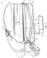
FIG. 2 is a cutaway elevational side view of theinventive grill 2; -
FIG. 3 is a perspective view of anembodiment 10 of the inventive module for radiating heat energy; -
FIG. 4 is a cutaway perspective view of theinventive heating module 10 having a food support grate 14 positioned thereon; -
FIG. 5 is an enlarged view of thesection 15, identified inFIG. 4 , of the inventiveheat radiating module 10; -
FIG. 6 is a cutaway perspective view of theinventive heating module 10 without a food support grate being positioned thereon; -
FIG. 7 is an enlarged view of thesection 25, identified inFIG. 6 , of the inventiveheat radiating module 10; -
FIG. 8 is a rotated cutaway perspective view of theinventive heating module 10 having the food support grate 14 positioned thereon; -
FIG. 9 is an enlarged view of thesection 35, identified inFIG. 8 , of the inventiveheat radiating module 10; -
FIG. 10 is a perspective view of an alternativerectangular embodiment 100 of the inventive electric grill and an alternativerectangular embodiment 105 of the inventive electric module for radiating heat energy; and -
FIG. 11 is a cutaway perspective view of analternative embodiment 110 of the inventive electrically-powered module for radiating heat energy comprising inverted U-shapedfood support ribs 122. -
FIG. 12 is a cutaway perspective view of anembodiment 210 of an electrically powered module for radiating heat energy comprising aflat emitter plate 224. -
FIG 13 is an enlarged view of the Detail A, identified inFIG. 12 , of theheat radiating module 210. -
FIG. 14 is a cutaway perspective view of analternative embodiment 310 of the inventive electrically powered module for radiating heat energy comprising anemitter plate 324 with a flat bottom. -
FIG. 15 is an enlarged view of the Detail B, identified inFIG. 14 , of the inventiveheat radiating module 310. -
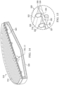
FIG. 16 is a perspective view of anembodiment 400 of an infrared cooking grate assembly provided by the present invention. -
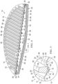
FIG. 17 is a cutaway perspective view of the inventive infraredcooking grate assembly 400. -
FIG. 18 is an enlarged view of the Detail C, identified inFIG. 17 , of the inventivecooking grate assembly 400. -
FIG. 19 is a perspective view of anembodiment 500 of the infrared cooking grate assembly provided by the present invention. -
FIG. 20 is a cutaway perspective view of the inventive infraredcooking grate assembly 500. -
FIG. 21 is an enlarged view of the Detail D, identified inFIG. 20 , of the inventivecooking grate assembly 500. - An
embodiment 2 of an outdoor electric grill provided by the present invention is shown inFIGS. 1-3 . The inventiveelectric grill 2 preferably comprises: abase housing 4; a support frame, housing, orother support structure 6 upon which thebase housing 4 is mounted; alid 8 which is pivotably attached to thebase housing 4 or is otherwise provided for opening and closing the top of thebase housing 4; an inventive electrically-poweredheat radiating module 10 which is positioned within or at least partially within theupper portion 12 of thebase housing 4; afood support grate 14 which is positioned on theheat radiating module 10; a drip pan orcup 16 in or beneath thebase housing 4; and anexterior control panel 18 extending from thebase housing 4. - An embodiment of the inventive electrically-powered
heat radiating module 10 is further illustrated inFIGS. 3-9 . Theinventive module 10 comprises: amodule housing 20 having aheating cavity 22 therein; anemitter plate 24 on or in anupper portion 26 of themodule housing 20; at least oneelectric heating element 28 positioned in theheating cavity 22 beneath theemitter plate 24; and electrical power leads 30 which preferably extend through the upwardly extending interior andexterior side walls module housing 20. - The
electric heating element 28 used in theheat radiating module 10 can be generally any type of electrical heating element which will radiate heat when current is applied. Theelectric heating element 28 will preferably be a tubular-type electric resistive heater. Tubular-type electric resistive heaters typically comprise a resistive metal wire which is mounted inside a metal tube filled with an electrically resistive but thermally conductive material such as, e.g., magnesium oxide. When an electrical current is applied to the metal wire, the outer metal tube, or sheath, will typically be heated to a temperature of up to as much as 1,000° to 1,200°F or more. - Alternatively, the
electric heating element 28 could be, for example, a high intensity infrared lamp element or an open ribbon resistive heater. In addition, if two or more separateelectrical elements 28 are used in theinventive radiating module 10, theelements 28 can be separately controlled or can be operable such that any ratio of the power supply to the unit can be transmitted to theelements 28, so long as the total power consumed does not exceed, for example, the standard 1800 watt limit provided by electrical outlets in the U.S. or the standard 1500 watt limit provided by electrical outlets in Canada. Theelements 28 could also be controlled to allow all of the power to be switched to one of theelements 28. - The
housing 20 of the inventiveheat radiating module 10 comprises: a heatingcavity bottom wall 36 beneath the heating element(s) 28; aninner side wall 32 which extends upwardly from the perimeter of the heatingcavity bottom wall 36 and laterally surrounds theheating cavity 22; anexterior bottom wall 38 of themodule housing 20 which is outside of and spaced apart from the heatingcavity bottom wall 36; abottom gap 40 defined between the heatingcavity bottom wall 36 and theexterior bottom wall 38 of themodule housing 20; at least one layer of insulatingmaterial 42 provided in thebottom gap 40 beneath theheating cavity 22; anexterior side wall 34 of thehousing 20 which extends upwardly from the perimeter of theexterior bottom wall 38 and laterally surrounds theinner side wall 32; an upwardly extendinggap 44 defined between theinner side wall 32 and theexterior side wall 34; at least one layer of insulatingmaterial 46 which is provided in the upwardly extendinggap 44 such that the insulatinglayer 46 laterally surrounds theheating cavity 22; and at least one infrared reflectiveradiation barrier surface 48 provided in theheating cavity 22 beneath the heating element(s) 28. - The reflective
radiation barrier surface 48 can be the upper surface of the heatingcavity bottom wall 36 or can be the upper surface of another wall within theheating cavity 22 positioned on or above the heatingcavity bottom wall 36. When eachelectric element 28 is heated, it transmits radiant heat energy in both an upward direction and a downward direction. Typically, in most prior art electric grills, the radiant heat energy transmitted from bottom side of the element is mostly lost. However, in theinventive grill 2, the radiant energy transmitted from the bottom side of theelectric heating element 28 is reflected upwardly by theradiation barrier surface 48 to theemitter plate 24 for (a) cooking the food more efficiently, (b) assisting in reducing the warmup time of theinventive grill 2, and (c) achieving higher cooking and searing temperatures. Theradiation barrier surface 48 can be formed of any temperature resistant infrared reflective material which is effective for achieving these results. Theradiation barrier surface 48 is preferably formed of reflective aluminum or stainless steel in single or multiple layers. - To further reduce the loss of heat from the
heating cavity 22, the exterior bottom of theheating cavity 22 is covered, as indicated above, by the layer of insulatingmaterial 42 provided in thebottom gap 40. In addition, theheating cavity 22 is also surrounded laterally by the above-mentioned layer of insulatingmaterial 46 which is provided in the upwardly extendinggap 44. The insulating layers 42 and 46 can be formed of any insulating material suitable for use at temperatures of as much as 1500° F or more and will preferably be formed of non-flammable cotton or fiber glass. - It will also be understood that the
lid 8 of theinventive grill 2 can also optionally include heat reflective and/or insulating surfaces or materials in order to further decrease warm up time, and increase overall efficiency. By way of example, but not way of limitation, examples of such features which can be used in thelid 8 are provided inUS Patent No. 6,104,004 . - The
emitter plate 24 of the inventiveheat radiating module 10 has an upper emittingsurface 50. The upper emittingsurface 50 has ridges and valleys provided thereon. To operate more effectively in conjunction with thefood support grate 14 to facilitate the flow of fat drippings off of theemitter plate 24 and to reduce or prevent flare-ups even at the higher operating temperatures provided by the inventiveelectric grill 2, the upper emittingsurface 50 comprises an alternating series ofridges 52 andvalleys 54. - The
emitter plate 24 shown inFIGS. 3-9 can be preferably stamped, cast or molded, or otherwise produced from a sheet of material so that corresponding ridges and valleys are also formed on thebottom side 56 of theemitter plate 24. Theflat emitter plate 224 shown inFIGS. 12 and 13 , on the other hand, can also be cast, molded, etc., or can be formed, for example, of ceramic glass or a metallic plate. - In another
alternative embodiment 310 of the inventive heat radiating module illustrated inFIGS. 14 and 15 , theemitter plate 324 thereof can be cast or molded out of a suitable material such that thebottom side 327 of theemitter plate 324 is a flat surface but the upper emittingsurface 350 hasridges 352 andvalleys 354 formed therein. Examples of suitable materials for forming theemitter plate 324 include, but are not limited to, procelainized iron or steel, stainless steel, or ceramic glass. - The inventive
heat radiating module emitter plate cooking grate plate - Although other shapes can also be used, the
ridges 52 of theemitter plate 24 shown inFIGS. 3-9 as well as the ridges of theemitter plates FIGS. 11 and14-15 will preferably have either (a) an inverted V shape with a peak 58 which can be sharp or rounded or (b) an angled lower portion which is combined with an upper peak portion having more of an inverted U shape. Similarly, thevalleys 54 of the emitter plate 24 (as well as those of theemitter plates 124 and 324) will preferably havebottoms 60 which are sharply angled, rounded, or U-shaped. Each of theridges 52 of theemitter plate 24, and of theemitter plates FIGS. 11 and14-15 , will preferably have a height in the range of from about 0.125 to about 0.375 inches and a base width in the range of from about 0.25 to about 0.5 inches. - The upper emitting
surface 50 of theemitter plate 24, as well as the upper emitting surfaces of theemitter plates FIGS 11-15 , will preferably be formed of a suitable high temperature material or coating which has an emissivity of at least 0.4 and which more preferably has an emissivity in the range of from about 0.5 to about 0.9. Examples of suitable materials for forming theemitter plate 24 include, but are not limited to, porcelain-coated steel, titanium, stainless steel, and aluminized or galvanized steel. Theemitter plate 24 will preferably be formed of porcelain-coated steel or 304 stainless steel. - The
food support grate 14 shown inFIGS 3-5 and8-9 comprises a plurality of side-by-sidefood support ribs 65 havinggaps 66 therebetween. Theribs 65 are solid structures which, in cross section, have a partial, inverted V shape. Theribs 65 haveupper surfaces 68 which together form afood support surface 70 which is spaced above the upper emittingsurface 50 of theemitter plate 24. Theribs 65 also havebottom portions 72 which are positioned in thevalleys 54 of theemitter plate 24 such that shieldedflow channels 74 for the fat and water which falls onto theemitter plate 24 during the cooking process are defined in thevalleys 54 beneath thebottom portions 72 of theribs 65. - The
food support ribs FIGS. 11 and14-15 , on the other hand, have a hollow, inverted U shape. However, theribs ribs - It will also be understood, however, that the food support ribs used in any of the embodiments of the present invention can alternatively have a rectangular shape, a sharp or rounded inverted V shape, or generally any other shaped desired. Also, the
ribs FIGS. 4 and 5 , at least partially hollow structures, or hollow structures as illustrated inFIGS. 11-15 . In addition, thebottoms hollow ribs FIGS. 11-15 , or closed. The upper surfaces 68, 126, 226, 326 of thefood support ribs FIGS. 4 and 5 , rounded surfaces as illustrated inFIGS. 11-15 , or sharp or rounded peaks or edges. By way of example, but not by way of limitation, thefood support grate - To reduce flare-ups in the past, in addition to operating at lower temperatures, the height of the food support ribs used in the prior art electric grills have typically been 0.75 inch or more. Tall ribs of this height have been necessary in order to sufficiently reduce the amount of oxygen available for combustion at the bottom of the gaps between the ribs. However, these tall ribs have also further reduced the efficiency of the prior art grills.
- For the inventive
heat radiating module 10 shown inFIGS. 3-9 , and as will also be true for thealternative modules FIGS. 11 and14-15 , the shieldedflow channels 74 created beneath the food support ribs operate to reduce the amount of oxygen available to the fat which flows into and through theflow channels 74 to such a degree that, even at the higher operating temperatures which are provided by theinventive grill 2, theinventive grill 2 will still be highly flare-up resistant at a much shorter, and more efficient, rib height of 0.5 inch or less. Consequently, although taller food support ribs can also be used, and may be desirable for example when using an alternativeflat emitter plate 224 as illustrated inFIGS. 12 and 13 , the food support ribs of thefood support grate - Moreover, by preventing flare-ups at significantly higher operating temperatures, the shielded
flow channels 74 formed by theemitter plate 24 124, 324 and thefood support grate inventive grill 2 also (a) cause a greater amount of vaporization and smoke generation to occur for flavoring the food and (b) prevent theemitter plate - Although not mandatory, the
food support grate inventive grill 2 will preferably be removably positionable on the upper emittingsurface emitter plate emitter plate housing heat radiating module - In the inventive
heat radiation module 10 as illustrated inFIGS. 4-9 , and as will also be the case inmodules corrugated ridges 80 or other shapes corresponding to theridges 52 andvalleys 54 of theemitter plate 24 are provided in the upper ends of the upwardly extendinginner side wall 32,exterior side wall 34, and insulatinglayer 46 of themodule housing 20 for placement of theemitter plate 24 on thehousing 20. Theupper end 82 of theinner side wall 32 defines the outer perimeter of theupper end 84 of theheating cavity 22. Theupper end 86 of theexterior side wall 34 defines the outer perimeter of theupper end 83 of themodule housing 20. - Still referring to
FIGS. 4-9 for purposes of illustration, the liquefied fat and water which drips onto theemitter plate 24 from the food product quickly enters theflow channels 74 beneath theribs 65 throughgaps 85 existing between thebottom contacting edges 88 of theribs 65 and thevalley walls 90 of the upper emittingsurface 50 of theemitter plate 24. Thesegaps 85 exist as a natural consequence of the fact that the stamping, casting, shearing, bending, and/or other procedures used for forming the components of theheat radiating module 10 and thefood support grate 14 do not provide a precise, theoretical line to line contact between thefood support ribs 65 and theemitter plate 24. Consequently, the low viscosity of the hot liquefied fat allows it to flow quite readily through thesmall gaps 85 and into theflow channels 74. - As the liquefied fat enters the shielded
flow channels 74, it flows toward the edge of theemitter plate 24. Thevalleys 54 of the upper emittingsurface 50 of theemitter plate 24 extend at least as far as, and more preferably beyond, theouter perimeter 86 of theupper end 83 of themodule housing 20 so that the liquefied fat and water from the food product falls from the outer ends of thevalleys 54 into theinterior cavity 92 of thegrill base housing 4 outside of thehousing 20 of the inventiveheat radiating module 10. - Similarly, although not falling within the scope of the claims, if an entirely
flat emitter plate 224 or an emitter plate with other features provided thereon is used, the outer perimeter of the emitter plate will preferably extend at least as far as, and more preferably beyond, the outer perimeter of the upper end of the module housing. - If desired, the
emitter plate 24 or thevalleys 54 thereof can be oriented, formed, or configured at a slight angle as mentioned above to facilitate and/or accelerate the flow of the liquefied fat and water off of theemitter plate 24. - Due to (a) the isolation of the heating element(s) 28 in the inventive
heat radiating module 20 and (b) thethermal insulation 42 provided beneath the bottom of themodule heating cavity 22, the temperatures in thebottom portion 94 of thegrill base housing 4 beneath theheat radiating module 10 are too low for ignition of the liquefied fat to occur. Consequently, the liquefied fat and water which fall onto thebottom wall 96 of thegrill base housing 4 simply flow into the drip pan orcup 16 for recovery. Although theinterior bottom wall 96 of thegrill base housing 4 is illustrated inFIG. 2 as being substantially flat, it will be understood that bottom 96 can be downwardly sloped to further facilitate the drainage of the fat into the drip pan orcup 16 located on or beneath the bottom 96. - In the inventive electrically-powered
module 10 for radiating heat energy, as well as in each of theother embodiments heating cavity 22 of the module is preferably significantly smaller than the firebox cavity volumes heretofore used in prior art electric grills for holding the electric heating element. Referring toFIGS. 4-9 for purposes of illustration, given any area of A in2 for theupper end 84 of theheating cavity 22 beneath theemitter plate 24, the volume of theheating cavity 22 below theemitter plate 24 will preferably not be more than (3 x A) in3 and will more preferably not be more than (1.5 x A) in3. Most preferably, the volume of theheating cavity 22 will not be greater than A in3. - This much smaller volume of the
heating cavity 22 beneath the emitter plate 24 (a) further increases the reflection and recovery of the radiant energy which is emitted downwardly from the heating element(s) 28 or which is otherwise directed toward the bottom of theheating cavity 22 and (b) reduces the volume of air in thecavity 22 which must be heated and maintained at operating temperature. In addition, the reduced depth of theheating cavity 22 produces an appealing thinner profile for theinventive grill 2 and reduces material costs. - More preferably, the dimensions of the
smaller heating cavity 22 of the inventive heat radiating module will be such that: (a) the vertical distance from thebottom wall 36 of theheating cavity 22 to the center of theemitter plate 24 will be in the range of from about 1.0 to about 3.0 inches and will more preferably be about 1.5 inches; (b) the vertical distance from thebottom wall 36 of theheating cavity 22 to the outer edge portion of theemitter plate 24 will be in the range of from about 0.5 to about 1.0 inches and will more preferably be about 0.5 inches; (c) the electric heating element(s) 28, which will typically have a diameter of about 0.3 inches, is/are in close proximity to or touching theemitter plate 24; (d) the vertical distance from the heating element(s) 28 to the center of theradiation surface barrier 48 will be in the range of from about 0.7 to about 2.7 inches and will more preferably be about 1.2 inches; and (e) the vertical distance from the heating element(s) 28 to the outer edge portion of theradiation surface barrier 48 will be in the range of from about 0.2 to about 0.7 inches and will more preferably be about 0.2 inches. - In addition, the
emitter plate upper end 84 of theheating cavity 22 such that theupper end 84 of theheating cavity 22 is at least 95% closed, more preferably at least 99% closed, to air flow into or out of theheating cavity 22 through theupper end 84 of thecavity 22. As used herein and in the claims, this means that the total area of all apertures, cracks, gaps, or other openings into theupper end 84 of theheating cavity 22 through theemitter plate edge 82 of theheating cavity 22 will preferably not be more than 5%, more preferably not more than 1%, of the area of theupper end 84 of theheating cavity 22. According to the invention, there are no openings through theemitter plate - Similarly, the
housing heat radiating module heating cavity 22. As used herein and in the claims, this means that the total area of all apertures, cracks, gaps, or other openings through the heatingcavity bottom wall 36 of thehousing inner side wall 32 of the housing which laterally surrounds theheating cavity 22 will preferably not be more than 5%, more preferably not more than 1%, of the total outer boundary limit area of theheating cavity 22 below the upper opening 84 (i.e., the total solid area of the inner surfaces of the heatingcavity bottom wall 36 and the upwardly extendinginner side wall 32 assuming that no cracks, gaps, or other openings are present). - By significantly reducing the size and/or number of, or substantially eliminating (or entirely eliminating), all cracks, gaps, or other air openings into the
heating cavity 22 of the inventiveheat radiating module emitter plate inventive grill 2. Moreover, this result is achieve in theinventive grill 2 even though the inventiveheat radiating module - In addition, the substantial closure of the
heating cavity 22 as described above reduces convective heat transfer to the food product and increases the percentage of total heat flux from infrared radiation at 3mm above thefood contacting surface 70 to more than 70% and more preferably at least 72%. Measurements taken during actual tests of theinventive grill 2 andmodule 10 ofFIGS. 1-9 indicated that infrared radiant energy accounted for 74.97% of the total heat flux. - The
emitter plate module housing surface emitter plate 24 into theheating cavity 22. As used herein and in the claims, this means that the total area of all apertures, cracks, gaps, or other openings through which fat or water from the food can flow into theupper end 84 of theheating cavity 22 through theemitter plate emitter plate edge 82 of theheating cavity 22 will preferably not be more than 5%, more preferably not more than 1%, of the area of theupper end 84 of theheating cavity 22. Most preferably, the inventive electrically-poweredheat radiating module heating cavity 22. - Preventing the flow or leakage of fat and water into the inventive heat radiating module (a) preserves, protects, and extends the life of the electric heating element(s) 28 and the bottom and
side insulating materials radiation barrier surface 48 in the bottom of theheating cavity 22 so that the effectiveness of theradiation barrier surface 48 for reflecting radiant energy upwardly toward theemitter plate heating cavity 22 eliminates the need for a drainage opening in the bottom of themodule housing heating cavity 22. - Because of the significant improvements in operation and thermal efficiency achieved by the
inventive grill 2 and the inventiveheat radiating module inventive grill 2 andmodule cooking surface 70 at the highest cooking setting of the inventiveheat radiating module lid 8 of thegrill 2 is closed and the heat radiating module is connected to a standard 120 volt, 1800 watt electrical outlet. - In actual tests of the inventive
electric grill 2 andheat radiating module 10 ofFIGS. 1-9 compared to a prior art electric grill of the same size built according to the specification ofUS 8,399,810 , theinventive grill 2 produced an average heat flux of 9.897 kW/m2 across the cooking surface versus a heat flux of 5.318 kW/m2 for the prior art grill, an improvement of 86%. In addition, the inventiveelectric grill 2 reached an average grate temperature of 464° F in just 15 minutes whereas the average grate temperature of the prior art electric grill after 15 minutes was only 153° F. - Moreover, with the
lid 8 closed, theinventive grill 2 is capable of achieving an ultimate high temperature at thecooking grate lid 8 open, the inventiveelectric grill 2 and the inventiveheat radiating module - Although various types of power and
cooking control systems 18 can be used for the inventiveelectric grill 2 and the inventiveheat radiating module controller 18 will preferably be a time proportional controller or a bimetallic, electrical controller of the type known in the art. Examples of other control systems which could be used include, but are not limited to, electric power controllers using either voltage or duty cycle control either with or without electronic thermostatic control. - The support frame, housing, or
other structure 6 upon which theinventive grill 2 is mounted can optionally include one pair, two pair, or any other desirednumber wheels 67 for easy movement and storage. - Although the inventive
electric module grill base housing 4, thehousing module interior cavity 92 of thegrill base housing 4 as a permanent, or at least more permanent,interior housing inventive grill 2 and the inventiveheat radiating module 10 include, but are not limited to: the use of one or more open ribbon resistance heaters as the heating element(s) 28 as mentioned above; and constructing the inventiveelectric grill 2 and the inventiveheat radiating module 105 in a rectangular shape, as illustrated inFIG. 10 , or oval or other shape rather than the circular shape illustrated inFIGS. 1-9 . - Also, as another alternative, it will be understood that the
emitter plate food support grate heat radiating modules - An example of one
such embodiment 400 of the inventive cooking grate assembly comprising afood support grate 414 of the same type shown inFIGS. 3-5 and8-9 removably positionable on anemitter plate 424 of the same type shown inFIGS. 3-9 is illustrated inFIGS. 16-18 . An example of anotherembodiment 500 of the inventive cooking grate assembly comprising afood support grate 514 of the same type shown inFIG. 11 removably positionable on anemitter plate 524 of the same type shown inFIG. 11 is illustrated inFIGS. 19-21 . The inventive cooking grate assemblies are highly resistant to flare-ups, are low cost, and provide a high percentage of infrared cooking energy. - Thus, the present invention is well adapted to carry out the objectives and attain the ends and advantages mentioned above as well as those inherent therein. While presently preferred embodiments have been described for purposes of this disclosure, numerous changes and modifications will be apparent to those of ordinary skill in the art. Such changes and modifications are encompassed within the invention as defined by the claims.
Claims (15)
- A module (10, 105, 110, 210, 310) for radiating heat energy for cooking food comprising:a module housing (20, 120, 220, 320) having a heating cavity (22) therein, said module housing (20, 120, 220, 320) having a housing exterior bottom wall (38) and an upwardly extending housing exterior side wall (34), said heating cavity (22) having a heating cavity bottom wall (36) and an upwardly extending heating cavity inner side wall (32), said heating cavity bottom wall (36) is positioned above said housing exterior bottom wall (38) to form a bottom gap (40) between said heating cavity bottom wall (36) and said housing exterior bottom wall (38), said heating cavity inner side wall (32) laterally surrounds said heating cavity (22), said housing exterior side wall (34) laterally surrounds and is spaced apart from said heating cavity inner side wall (32) to form an upwardly extending gap (44) between said housing exterior side wall (34) and said heating cavity inner side wall (32), said upwardly extending gap (44) laterally surrounds said heating cavity (22), an upper end (82) of said heating cavity inner side wall (32) defines an outer perimeter of an upper end (84) of said heating cavity (22), and an upper end (86) of said housing exterior side wall (34) defines an outer perimeter of an upper end (83) of said module housing (20, 120, 220, 320);
at least one layer of insulating material (42) between said housing exterior bottom wall (38) and said heating cavity bottom wall (36) and a layer of insulating material (46) in said upwardly extending gap (44) between said housing exterior side wall (34) and said heating cavity inner side wall (32), wherein at least one reflective radiation barrier surface (48) is provided in said heating cavity (22) beneath at least one heating element (28);an emitter plate (24, 124, 224, 324) on said upper end (83) of said module housing (20, 120, 220, 320), said emitter plate (24, 124, 224, 324) having an upper emitting surface (50, 150, 250, 350), said upper emitting surface (50, 150, 250, 350) comprising an alternating series of parallel ridges (52, 352) and valleys (54, 354), and said emitter plate (24, 124, 224, 324) having no openings therethrough; andthe at least one electric heating element (28) is positioned in said heating cavity (22) beneath said emitter plate (24, 124, 224, 324);wherein said emitter plate (24, 124, 224, 324) covers and closes said upper ends (84, 83) of said heating cavity (22) and said module housing (20, 120, 220, 320) such that said upper end (84) of said heating cavity (22) is at least 95% closed to air flow out of or into said upper end (84) of said heating cavity (22);said emitter plate (24, 124, 224, 324) and said module housing (20, 120, 220, 320) are at least 95% closed to flow from said upper emitting surface (50, 150, 250, 350) of said emitter plate (24, 124, 224, 324) into said heating cavity (22) of fat and water falling onto said upper emitting surface (50, 150, 250, 350) from said food; andeach end of each of said ridges (52, 352) and valleys (54, 354) of said upper emitting surface (50, 150, 250, 350) of said emitter plate (24, 124, 224, 324) extends at least as far as said outer perimeter (86) of said upper end (83) of said module housing (20, 120, 220, 320) so that fat and water which falls onto said upper emitting surface (50, 150, 250, 350) from said food is delivered by said ridges (52, 352) and valleys (54, 354) to a location outside of said module housing (20, 120, 220, 320). - The module (10, 105, 110, 210, 310) of claim 1 wherein said upper end (84) of said heating cavity (22) beneath said emitter plate (24, 124, 224, 324) has an area of A in2 and a total volume of said heating cavity (22) beneath said emitter plate (24, 124, 224, 324) is not more than (1.5 x A) in3.
- The module (10, 105, 110, 210, 310) of claim 1 further comprising a food support grate (14, 114, 214, 314) which is positionable on said emitter plate (24, 124, 224, 324), said food support grate (14, 114, 214, 314) having a food support surface (70) which is spaced above said upper emitting surface (50, 150, 250, 350) of said emitter plate (24, 124, 224, 324).
- The module (10, 105, 110, 210, 310) of claim 3 wherein:said food support grate (14, 114, 214, 314) comprises a plurality of food support ribs (65, 122, 222, 322) having upper surfaces (68, 126, 226, 326) and bottom portions (72, 125, 225, 325);said food support surface (70) comprises said upper surfaces (68, 126, 226, 326) of said food support ribs (65, 122, 222, 322);said bottom portions (72, 125, 225, 325) of food support ribs (65, 122, 222, 322) are positioned in said valleys (54, 354) of said upper emitting surface (50, 150, 250, 350) when said food support grate (14, 114, 214, 314) is positioned on said emitter plate (24, 124, 224, 324); and,when said food support grate (14, 114, 214, 314) is positioned on said emitter plate (24, 124, 224, 324), flow channels for fat and water falling onto said upper emitting surface (50, 150, 250, 350) from said food are defined in said valleys (54, 354) of said upper emitting surface (50, 150, 250, 350) beneath said bottom portions (72, 125, 225, 325) of said food support ribs (65, 122, 222, 322).
- The module (10, 105, 110, 210, 310) of claim 4 wherein, at a highest heat setting of said module (10, 110, 210, 310) when connected to a standard US 120 volt, 1800 watt electrical outlet, an average heat flux for a total cooking area at said food support surface (70) of at least 7.5 kW/m2 is produced.
- The module (10, 105, 110, 210, 310) of claim 1 wherein:a bottom side (56) of said emitter plate (24, 124, 224, 324) comprises ridges and valleys corresponding to said alternating series of ridges (52, 352) and valleys (54, 354) of said upper emitting surface (50, 150, 250, 350) of said emitter plate (24, 124, 224, 324) andsaid upper end (86) of said housing exterior side wall (34), said upper end (82) of the upwardly extending inner side wall (32), and the upper end of said insulating layer (46) have corrugation ridges (80) formed therein in which said ridges (52, 352) and valleys (54, 354) of said emitter plate (24, 124, 224, 324) are received.
- The module (10, 105, 110, 210, 310) of claim 6 wherein each of said ends of said valleys (54, 354) of said upper emitting surface (50, 150, 250, 350) extends beyond said outer perimeter (86) of said upper end portion (83) of said module housing (20, 120, 220, 320).
- An outdoor cooking grill (2) for grilling a food product comprising:a grill base housing (4) having an interior cavity with an interior bottom (96);a lid (8) for opening and closing said grill base housing (4);a module (10, 105, 110, 210, 310) for radiating heat energy according to claim 1; anda food support grate (14, 114, 214, 314) on said upper emitting surface (50, 150, 250, 350) of said emitter plate (24, 124, 224, 324), said food support grate (14, 114, 214, 314) having a food support surface (70) which is spaced above said upper emitting surface (50, 150, 250, 350) of said emitter plate (24, 124, 224, 324.
- The outdoor cooking grill (2) of claim 8 further comprising a grease tray (16) on or beneath said interior bottom (96) of said interior cavity of said grill base housing (4) outside of said module (10, 105, 110, 210, 310).
- The outdoor cooking grill (2) of claim 8 wherein said upper end (84) of said heating cavity (22) beneath said emitter plate (24, 124, 224, 324) has an area of A in2 and a total volume of said heating cavity (22) beneath said emitter plate (24, 124, 224, 324) is not more than (1.5 x A) in3.
- The outdoor cooking grill (2) of claim 8 wherein:said food support grate (14, 114, 214, 314) comprises a plurality of food support ribs (65, 122, 222, 322) having upper surfaces (68, 126, 226, 326) and bottom portions (75, 125, 225, 325);said food support surface (70) comprises said upper surfaces (68, 126, 226, 326) of said food support ribs (65, 122, 222, 322);said bottom portions (75, 125, 225, 325) of food support ribs (65, 122, 222, 322) are positioned in said valleys (54, 354) of said upper emitting surface (50, 150, 250, 350) when said food support grate (70) is positioned on said emitter plate (14, 114, 214, 314); and,when said food support grate (14, 114, 214, 314) is positioned on said emitter plate (14, 114, 214, 314), flow channels for fat and water falling onto said upper emitting surface (50, 150, 250, 350) from said food product are defined in said valleys (54, 354) of said upper emitting surface (50, 150, 250, 350) beneath said bottom portions (75, 125, 225, 325) of said food support ribs (65, 122, 222, 322).
- The outdoor cooking grill (2) of claim 11 wherein each end of each of said ridges (52, 352) and valleys (54, 354) of said upper emitting surface (50, 150, 250, 350) extends at least as far as an outer perimeter of said upper end of said module housing (20, 120, 220, 320) so that said ridges (52, 352) and valleys (54, 354) will deliver fat and water falling onto said upper emitting surface (50, 150, 250, 350) of said emitter plate (24, 124, 224, 324) from said food product into said interior cavity of said grill base housing (4) outside of said module housing (20, 120, 220, 320).
- The outdoor cooking grill (2) of claim 12 wherein each of said ends of each of said ridges (52, 352) and valleys (54, 354) of said upper emitting surface (50, 150, 250, 350) extends beyond said outer perimeter of said upper end of said module housing (20, 120, 220, 320).
- The outdoor cooking grill (2) of claim 8 wherein, at a highest heat setting of said outdoor cooking grill (2) when connected to a standard US 120 volt, 1800 watt electrical outlet, an average heat flux for a total cooking area at said food support surface (70) of at least 7.5 kW/m2 is produced.
- The outdoor cooking grill (2) of claim 8 wherein said upper end (82) of said heating cavity inner side wall (32), said upper end (86) of said housing exterior side wall (34), and the upper end of said insulating layer (46) have corrugation ridges (80) formed therein in which said ridges (52, 352) and valleys (54, 354) of said emitter plate (24, 124, 224, 324) are received.
Applications Claiming Priority (2)
| Application Number | Priority Date | Filing Date | Title |
|---|---|---|---|
| US201462040016P | 2014-08-21 | 2014-08-21 | |
| PCT/US2015/044647 WO2016028549A1 (en) | 2014-08-21 | 2015-08-11 | High performance electric grill, method, and heat radiating module |
Publications (3)
| Publication Number | Publication Date |
|---|---|
| EP3183939A1 EP3183939A1 (en) | 2017-06-28 |
| EP3183939A4 EP3183939A4 (en) | 2018-04-11 |
| EP3183939B1 true EP3183939B1 (en) | 2025-05-28 |
Family
ID=55347189
Family Applications (1)
| Application Number | Title | Priority Date | Filing Date |
|---|---|---|---|
| EP15833595.0A Active EP3183939B1 (en) | 2014-08-21 | 2015-08-11 | High performance electric grill, method, and heat radiating module |
Country Status (6)
| Country | Link |
|---|---|
| US (1) | US10034578B2 (en) |
| EP (1) | EP3183939B1 (en) |
| CN (1) | CN107006080B (en) |
| AU (1) | AU2015305920B2 (en) |
| CA (1) | CA2955398A1 (en) |
| WO (1) | WO2016028549A1 (en) |
Families Citing this family (21)
| Publication number | Priority date | Publication date | Assignee | Title |
|---|---|---|---|---|
| USD792148S1 (en) * | 2015-10-10 | 2017-07-18 | Shu-Jui Chung | Barbecue grill |
| CN107305025A (en) * | 2016-04-20 | 2017-10-31 | 佛山市顺德区美的电热电器制造有限公司 | A kind of Far-infrared Heating disk and far infrared cooking equipment |
| CN110200516A (en) | 2017-08-09 | 2019-09-06 | 沙克忍者运营有限责任公司 | Cooking system |
| AU201811305S (en) * | 2017-10-25 | 2018-03-28 | Mor Designs Ltd | Barbeque |
| CN107713791A (en) * | 2017-11-06 | 2018-02-23 | 四川大学 | A kind of barbecue apparatus |
| US10555377B2 (en) * | 2017-11-29 | 2020-02-04 | Shenzhen Chenbei Technology Co., Ltd. | Warmer with integrated heating module |
| USD914436S1 (en) | 2018-06-19 | 2021-03-30 | Sharkninja Operating Llc | Air diffuser with food preparation pot |
| USD934027S1 (en) | 2018-08-09 | 2021-10-26 | Sharkninja Operating Llc | Reversible cooking rack |
| USD903413S1 (en) | 2018-08-09 | 2020-12-01 | Sharkninja Operating Llc | Cooking basket |
| USD883015S1 (en) | 2018-08-09 | 2020-05-05 | Sharkninja Operating Llc | Food preparation device and parts thereof |
| USD883014S1 (en) | 2018-08-09 | 2020-05-05 | Sharkninja Operating Llc | Food preparation device |
| DK3695761T3 (en) * | 2019-02-14 | 2022-12-05 | Severin Elektrogeraete Gmbh | Grill appliance with reflector tray |
| WO2020176477A1 (en) | 2019-02-25 | 2020-09-03 | Sharkninja Operating Llc | Cooking system with guard |
| US11033146B2 (en) | 2019-02-25 | 2021-06-15 | Sharkninja Operating Llc | Cooking device and components thereof |
| USD982375S1 (en) | 2019-06-06 | 2023-04-04 | Sharkninja Operating Llc | Food preparation device |
| USD918654S1 (en) | 2019-06-06 | 2021-05-11 | Sharkninja Operating Llc | Grill plate |
| US11647861B2 (en) | 2020-03-30 | 2023-05-16 | Sharkninja Operating Llc | Cooking device and components thereof |
| EP4188168A4 (en) * | 2020-07-31 | 2024-10-23 | W.C. Bradley Co. | ELECTRIC GRILL AND SMOKING DEVICE |
| US20220257055A1 (en) * | 2021-02-14 | 2022-08-18 | Robert Falken | Grilling grate for a grilling apparatus |
| US20220275948A1 (en) * | 2021-03-01 | 2022-09-01 | Nuwave, Llc | Convection Oven with Removable Grill Plate |
| CN116763160A (en) * | 2023-07-04 | 2023-09-19 | 东莞市昊鸿户外用品科技有限公司 | Intelligent electric oven |
Family Cites Families (41)
| Publication number | Priority date | Publication date | Assignee | Title |
|---|---|---|---|---|
| US3490359A (en) | 1967-09-20 | 1970-01-20 | Charles E Seitz | Electric charbroiler |
| US3623422A (en) | 1970-10-02 | 1971-11-30 | Edward M Marshall | Food cooking grill |
| US3805688A (en) | 1972-05-16 | 1974-04-23 | Gen Electric | Electric broiler |
| US3946651A (en) | 1974-01-29 | 1976-03-30 | Garcia Joel H | Broiler |
| US4403597A (en) | 1981-01-16 | 1983-09-13 | Miller Don J | Heat transfer device |
| GB2170144B (en) | 1985-01-24 | 1988-12-21 | Simon Barron Ltd | A system for producing fuel pellets |
| US4862795A (en) | 1988-06-06 | 1989-09-05 | General Electric Company | Cooktop grill with improved reflector pan |
| US5277106A (en) | 1990-07-02 | 1994-01-11 | The Thermos Company, Inc. | Easily assembled barbecue grill with heat distribution plate |
| US5197379A (en) | 1992-01-07 | 1993-03-30 | Leonard Jr Gustav | Outdoor cooker |
| US5276307A (en) * | 1992-06-11 | 1994-01-04 | Rival Manufacturing Company | Electrical appliance with hermetically sealed connector having venting means |
| AU673831B2 (en) | 1992-09-29 | 1996-11-28 | Thermos Company, The | Lifestyle barbecue grill |
| US5355780A (en) | 1993-03-09 | 1994-10-18 | Campbell Michael F | Flame inhibiting grate for a cooking grill |
| US5355868A (en) | 1993-06-04 | 1994-10-18 | Greene Manufacturing Co. | Heat distribution article for cooking grills |
| US5603256A (en) | 1993-08-13 | 1997-02-18 | The Thermos Company | Barbecue grill |
| JPH07231853A (en) | 1993-12-27 | 1995-09-05 | Arco Kogyo Kk | Heat cooking device |
| US5488897A (en) * | 1994-05-11 | 1996-02-06 | Griller's World Inc. | Cooking apparatus |
| US5719377A (en) | 1994-08-15 | 1998-02-17 | Sunbeam Products, Inc. | Dual heating element electric grill having a smoker heating element for vaporizing grease and juices from foodstuff |
| US5467691A (en) | 1994-11-01 | 1995-11-21 | Modern Home Products Corp. | Cooking grid |
| US5735260A (en) | 1996-04-30 | 1998-04-07 | Hanover Catalog Holdings, Inc. | Tile for use with a cooking grill |
| US6104004A (en) | 1997-04-10 | 2000-08-15 | Atd Corporation | Electric barbecue grill |
| US5845562A (en) * | 1998-04-03 | 1998-12-08 | Keystone Mfg. Co., Inc. | Electric grill |
| WO2000001286A1 (en) * | 1998-07-02 | 2000-01-13 | Best Willie H | Heating assembly and cooking apparatus |
| US5974954A (en) | 1998-08-25 | 1999-11-02 | Empire Comfort Systems, Inc. | Barbecue grill grate |
| US5911812A (en) | 1998-10-14 | 1999-06-15 | Stanek; Michael | Barbecue grille with fluid runoff control |
| US6314870B1 (en) | 1999-07-07 | 2001-11-13 | Advanced Catalyst Systems, Llc | Catalytic drip pan for cooking devices |
| US7066169B2 (en) | 2000-03-13 | 2006-06-27 | Ronald Feldewerth | Grilling surface for gas grill providing flame control and grease diversion |
| CA2363985A1 (en) | 2001-05-24 | 2002-11-24 | Fiesta Barbeques Limited | Supported gas barbeque assembly |
| US6520174B1 (en) | 2001-11-28 | 2003-02-18 | Luigi Scigliuolo | Two stage fire control barbecue cooking apparatus |
| US6795348B2 (en) | 2002-05-29 | 2004-09-21 | Micron Technology, Inc. | Method and apparatus for erasing flash memory |
| CA2571395C (en) | 2004-06-23 | 2011-08-16 | Willie H. Best | Radiant burner |
| US7810487B2 (en) | 2005-12-01 | 2010-10-12 | W.C. Bradley Company | Apparatus and methods for providing an improved cooking grate for an outdoor cooking grill |
| US8631739B2 (en) | 2006-06-22 | 2014-01-21 | Kenyon International, Inc. | Grill |
| ATE487408T1 (en) | 2006-09-26 | 2010-11-15 | Char Broil Llc | COOKING APPARATUS WITH CONCAVE RADIANT |
| EP2084460B1 (en) | 2006-11-10 | 2011-10-26 | Char-Broil, LLC | Radiant tube broiler |
| US8584580B2 (en) | 2008-01-22 | 2013-11-19 | Brad Barrett | System and device for grilling foods |
| US9814352B2 (en) | 2008-06-12 | 2017-11-14 | Char-Broil, Llc | Cooking grates and grills incorporating such grates |
| CN102186389A (en) * | 2008-10-17 | 2011-09-14 | 查尔-布洛伊尔有限责任公司 | Parallel tube burner with improved cooling and reduced size |
| EP2384135B1 (en) * | 2008-12-01 | 2013-08-14 | Char-Broil, LLC | Methods and apparatus for generating infrared radiation from convective products of combustion |
| US8399810B2 (en) | 2009-08-11 | 2013-03-19 | W. C. Bradley Co. | Electric patio bistro |
| BR112013010729A2 (en) * | 2010-12-17 | 2016-08-09 | Bradley W C Co | grill set for cooking and grill set |
| DK2849618T3 (en) * | 2012-05-15 | 2018-10-22 | Bradley W C Co | Flame resistant cooking grate and cooking equipment |
-
2015
- 2015-08-11 EP EP15833595.0A patent/EP3183939B1/en active Active
- 2015-08-11 AU AU2015305920A patent/AU2015305920B2/en active Active
- 2015-08-11 CN CN201580044617.6A patent/CN107006080B/en active Active
- 2015-08-11 WO PCT/US2015/044647 patent/WO2016028549A1/en not_active Ceased
- 2015-08-11 US US14/823,408 patent/US10034578B2/en active Active
- 2015-08-11 CA CA2955398A patent/CA2955398A1/en not_active Abandoned
Also Published As
| Publication number | Publication date |
|---|---|
| AU2015305920B2 (en) | 2020-08-27 |
| AU2015305920A1 (en) | 2017-02-09 |
| EP3183939A4 (en) | 2018-04-11 |
| CN107006080A (en) | 2017-08-01 |
| EP3183939A1 (en) | 2017-06-28 |
| CA2955398A1 (en) | 2016-02-25 |
| CN107006080B (en) | 2020-10-23 |
| WO2016028549A1 (en) | 2016-02-25 |
| US10034578B2 (en) | 2018-07-31 |
| US20160051089A1 (en) | 2016-02-25 |
Similar Documents
| Publication | Publication Date | Title |
|---|---|---|
| US10034578B2 (en) | High performance electric grill, method, and heat radiating module | |
| US8399810B2 (en) | Electric patio bistro | |
| US11242998B2 (en) | Radiation grill | |
| US11013368B2 (en) | Radiation grill | |
| US20220031107A1 (en) | Electric grill and smoking device | |
| EP2849618B1 (en) | Flame resistant cooking grate and cooking apparatus | |
| US20230366560A1 (en) | Cooking chamber insert with a specific basic structure, and cooking device | |
| CN113491450A (en) | Cooking utensil | |
| CA2691833C (en) | Product warming apparatus | |
| US3490359A (en) | Electric charbroiler | |
| US6288369B1 (en) | Cooking apparatus | |
| KR200322769Y1 (en) | Combination gas-electric range | |
| KR20130000651U (en) | The multipurpose roast pan that compound cooking is possible | |
| KR200197438Y1 (en) | Cooker | |
| JP3038527U (en) | Gas barbecue grill | |
| CN111642983A (en) | Barbecue grill | |
| JP2004065536A (en) | Cooking device | |
| KR100596193B1 (en) | Heat storage cooker | |
| KR101314084B1 (en) | Roasting utensil | |
| CN116669602A (en) | Electric Grills and Smokers | |
| WO1999007267A1 (en) | Cooking apparatus and grill assembly thereof | |
| KR200389743Y1 (en) | The cooker of using a regenerator | |
| JP2014009909A (en) | Cooker with ceramic far infrared radiation means | |
| JP2012011203A (en) | Cooking appliance with bowl and reflector | |
| JP2004208812A (en) | Hot plate |
Legal Events
| Date | Code | Title | Description |
|---|---|---|---|
| STAA | Information on the status of an ep patent application or granted ep patent |
Free format text: STATUS: THE INTERNATIONAL PUBLICATION HAS BEEN MADE |
|
| PUAI | Public reference made under article 153(3) epc to a published international application that has entered the european phase |
Free format text: ORIGINAL CODE: 0009012 |
|
| STAA | Information on the status of an ep patent application or granted ep patent |
Free format text: STATUS: REQUEST FOR EXAMINATION WAS MADE |
|
| 17P | Request for examination filed |
Effective date: 20170124 |
|
| AK | Designated contracting states |
Kind code of ref document: A1 Designated state(s): AL AT BE BG CH CY CZ DE DK EE ES FI FR GB GR HR HU IE IS IT LI LT LU LV MC MK MT NL NO PL PT RO RS SE SI SK SM TR |
|
| AX | Request for extension of the european patent |
Extension state: BA ME |
|
| DAV | Request for validation of the european patent (deleted) | ||
| DAX | Request for extension of the european patent (deleted) | ||
| A4 | Supplementary search report drawn up and despatched |
Effective date: 20180314 |
|
| RIC1 | Information provided on ipc code assigned before grant |
Ipc: A47J 37/06 20060101AFI20180308BHEP |
|
| STAA | Information on the status of an ep patent application or granted ep patent |
Free format text: STATUS: EXAMINATION IS IN PROGRESS |
|
| 17Q | First examination report despatched |
Effective date: 20190313 |
|
| REG | Reference to a national code |
Ref country code: DE Ref legal event code: R079 Free format text: PREVIOUS MAIN CLASS: H05B0003680000 Ipc: A47J0037060000 Ref document number: 602015091748 Country of ref document: DE |
|
| GRAP | Despatch of communication of intention to grant a patent |
Free format text: ORIGINAL CODE: EPIDOSNIGR1 |
|
| STAA | Information on the status of an ep patent application or granted ep patent |
Free format text: STATUS: GRANT OF PATENT IS INTENDED |
|
| RIC1 | Information provided on ipc code assigned before grant |
Ipc: F24C 7/04 20060101ALI20250117BHEP Ipc: H05B 3/26 20060101ALI20250117BHEP Ipc: F24C 7/10 20060101ALI20250117BHEP Ipc: F24C 7/08 20060101ALI20250117BHEP Ipc: A47J 37/07 20060101ALI20250117BHEP Ipc: A47J 37/06 20060101AFI20250117BHEP |
|
| INTG | Intention to grant announced |
Effective date: 20250203 |
|
| GRAJ | Information related to disapproval of communication of intention to grant by the applicant or resumption of examination proceedings by the epo deleted |
Free format text: ORIGINAL CODE: EPIDOSDIGR1 |
|
| STAA | Information on the status of an ep patent application or granted ep patent |
Free format text: STATUS: EXAMINATION IS IN PROGRESS |
|
| GRAP | Despatch of communication of intention to grant a patent |
Free format text: ORIGINAL CODE: EPIDOSNIGR1 |
|
| STAA | Information on the status of an ep patent application or granted ep patent |
Free format text: STATUS: GRANT OF PATENT IS INTENDED |
|
| GRAS | Grant fee paid |
Free format text: ORIGINAL CODE: EPIDOSNIGR3 |
|
| GRAA | (expected) grant |
Free format text: ORIGINAL CODE: 0009210 |
|
| STAA | Information on the status of an ep patent application or granted ep patent |
Free format text: STATUS: THE PATENT HAS BEEN GRANTED |
|
| INTC | Intention to grant announced (deleted) | ||
| INTG | Intention to grant announced |
Effective date: 20250416 |
|
| AK | Designated contracting states |
Kind code of ref document: B1 Designated state(s): AL AT BE BG CH CY CZ DE DK EE ES FI FR GB GR HR HU IE IS IT LI LT LU LV MC MK MT NL NO PL PT RO RS SE SI SK SM TR |
|
| REG | Reference to a national code |
Ref country code: GB Ref legal event code: FG4D |
|
| REG | Reference to a national code |
Ref country code: CH Ref legal event code: EP |
|
| REG | Reference to a national code |
Ref country code: IE Ref legal event code: FG4D Ref country code: DE Ref legal event code: R096 Ref document number: 602015091748 Country of ref document: DE |
|
| REG | Reference to a national code |
Ref country code: NL Ref legal event code: MP Effective date: 20250528 |
|
| PG25 | Lapsed in a contracting state [announced via postgrant information from national office to epo] |
Ref country code: ES Free format text: LAPSE BECAUSE OF FAILURE TO SUBMIT A TRANSLATION OF THE DESCRIPTION OR TO PAY THE FEE WITHIN THE PRESCRIBED TIME-LIMIT Effective date: 20250528 Ref country code: FI Free format text: LAPSE BECAUSE OF FAILURE TO SUBMIT A TRANSLATION OF THE DESCRIPTION OR TO PAY THE FEE WITHIN THE PRESCRIBED TIME-LIMIT Effective date: 20250528 |
|
| REG | Reference to a national code |
Ref country code: LT Ref legal event code: MG9D |
|
| PG25 | Lapsed in a contracting state [announced via postgrant information from national office to epo] |
Ref country code: GR Free format text: LAPSE BECAUSE OF FAILURE TO SUBMIT A TRANSLATION OF THE DESCRIPTION OR TO PAY THE FEE WITHIN THE PRESCRIBED TIME-LIMIT Effective date: 20250829 Ref country code: NO Free format text: LAPSE BECAUSE OF FAILURE TO SUBMIT A TRANSLATION OF THE DESCRIPTION OR TO PAY THE FEE WITHIN THE PRESCRIBED TIME-LIMIT Effective date: 20250828 |
|
| PG25 | Lapsed in a contracting state [announced via postgrant information from national office to epo] |
Ref country code: NL Free format text: LAPSE BECAUSE OF FAILURE TO SUBMIT A TRANSLATION OF THE DESCRIPTION OR TO PAY THE FEE WITHIN THE PRESCRIBED TIME-LIMIT Effective date: 20250528 Ref country code: PL Free format text: LAPSE BECAUSE OF FAILURE TO SUBMIT A TRANSLATION OF THE DESCRIPTION OR TO PAY THE FEE WITHIN THE PRESCRIBED TIME-LIMIT Effective date: 20250528 |
|
| PG25 | Lapsed in a contracting state [announced via postgrant information from national office to epo] |
Ref country code: BG Free format text: LAPSE BECAUSE OF FAILURE TO SUBMIT A TRANSLATION OF THE DESCRIPTION OR TO PAY THE FEE WITHIN THE PRESCRIBED TIME-LIMIT Effective date: 20250528 |
|
| PG25 | Lapsed in a contracting state [announced via postgrant information from national office to epo] |
Ref country code: HR Free format text: LAPSE BECAUSE OF FAILURE TO SUBMIT A TRANSLATION OF THE DESCRIPTION OR TO PAY THE FEE WITHIN THE PRESCRIBED TIME-LIMIT Effective date: 20250528 |
|
| PG25 | Lapsed in a contracting state [announced via postgrant information from national office to epo] |
Ref country code: RS Free format text: LAPSE BECAUSE OF FAILURE TO SUBMIT A TRANSLATION OF THE DESCRIPTION OR TO PAY THE FEE WITHIN THE PRESCRIBED TIME-LIMIT Effective date: 20250828 |
|
| PG25 | Lapsed in a contracting state [announced via postgrant information from national office to epo] |
Ref country code: IS Free format text: LAPSE BECAUSE OF FAILURE TO SUBMIT A TRANSLATION OF THE DESCRIPTION OR TO PAY THE FEE WITHIN THE PRESCRIBED TIME-LIMIT Effective date: 20250928 |
|
| PG25 | Lapsed in a contracting state [announced via postgrant information from national office to epo] |
Ref country code: LV Free format text: LAPSE BECAUSE OF FAILURE TO SUBMIT A TRANSLATION OF THE DESCRIPTION OR TO PAY THE FEE WITHIN THE PRESCRIBED TIME-LIMIT Effective date: 20250528 |
|
| REG | Reference to a national code |
Ref country code: AT Ref legal event code: MK05 Ref document number: 1798128 Country of ref document: AT Kind code of ref document: T Effective date: 20250528 |
|
| PGFP | Annual fee paid to national office [announced via postgrant information from national office to epo] |
Ref country code: DE Payment date: 20251029 Year of fee payment: 11 |
|
| PGFP | Annual fee paid to national office [announced via postgrant information from national office to epo] |
Ref country code: GB Payment date: 20251027 Year of fee payment: 11 |
|
| PG25 | Lapsed in a contracting state [announced via postgrant information from national office to epo] |
Ref country code: DK Free format text: LAPSE BECAUSE OF FAILURE TO SUBMIT A TRANSLATION OF THE DESCRIPTION OR TO PAY THE FEE WITHIN THE PRESCRIBED TIME-LIMIT Effective date: 20250528 Ref country code: SM Free format text: LAPSE BECAUSE OF FAILURE TO SUBMIT A TRANSLATION OF THE DESCRIPTION OR TO PAY THE FEE WITHIN THE PRESCRIBED TIME-LIMIT Effective date: 20250528 Ref country code: AT Free format text: LAPSE BECAUSE OF FAILURE TO SUBMIT A TRANSLATION OF THE DESCRIPTION OR TO PAY THE FEE WITHIN THE PRESCRIBED TIME-LIMIT Effective date: 20250528 |
|
| PGFP | Annual fee paid to national office [announced via postgrant information from national office to epo] |
Ref country code: FR Payment date: 20251027 Year of fee payment: 11 |
|
| PG25 | Lapsed in a contracting state [announced via postgrant information from national office to epo] |
Ref country code: CZ Free format text: LAPSE BECAUSE OF FAILURE TO SUBMIT A TRANSLATION OF THE DESCRIPTION OR TO PAY THE FEE WITHIN THE PRESCRIBED TIME-LIMIT Effective date: 20250528 |
|
| PG25 | Lapsed in a contracting state [announced via postgrant information from national office to epo] |
Ref country code: EE Free format text: LAPSE BECAUSE OF FAILURE TO SUBMIT A TRANSLATION OF THE DESCRIPTION OR TO PAY THE FEE WITHIN THE PRESCRIBED TIME-LIMIT Effective date: 20250528 |
|
| PG25 | Lapsed in a contracting state [announced via postgrant information from national office to epo] |
Ref country code: SK Free format text: LAPSE BECAUSE OF FAILURE TO SUBMIT A TRANSLATION OF THE DESCRIPTION OR TO PAY THE FEE WITHIN THE PRESCRIBED TIME-LIMIT Effective date: 20250528 Ref country code: RO Free format text: LAPSE BECAUSE OF FAILURE TO SUBMIT A TRANSLATION OF THE DESCRIPTION OR TO PAY THE FEE WITHIN THE PRESCRIBED TIME-LIMIT Effective date: 20250528 |
|
| PG25 | Lapsed in a contracting state [announced via postgrant information from national office to epo] |
Ref country code: IT Free format text: LAPSE BECAUSE OF FAILURE TO SUBMIT A TRANSLATION OF THE DESCRIPTION OR TO PAY THE FEE WITHIN THE PRESCRIBED TIME-LIMIT Effective date: 20250528 |
|
| REG | Reference to a national code |
Ref country code: DE Ref legal event code: R097 Ref document number: 602015091748 Country of ref document: DE |
|
| REG | Reference to a national code |
Ref country code: CH Ref legal event code: H13 Free format text: ST27 STATUS EVENT CODE: U-0-0-H10-H13 (AS PROVIDED BY THE NATIONAL OFFICE) Effective date: 20260324 |
|
| PG25 | Lapsed in a contracting state [announced via postgrant information from national office to epo] |
Ref country code: MC Free format text: LAPSE BECAUSE OF FAILURE TO SUBMIT A TRANSLATION OF THE DESCRIPTION OR TO PAY THE FEE WITHIN THE PRESCRIBED TIME-LIMIT Effective date: 20250528 |
|
| PLBE | No opposition filed within time limit |
Free format text: ORIGINAL CODE: 0009261 |
|
| STAA | Information on the status of an ep patent application or granted ep patent |
Free format text: STATUS: NO OPPOSITION FILED WITHIN TIME LIMIT |
|
| REG | Reference to a national code |
Ref country code: CH Ref legal event code: L10 Free format text: ST27 STATUS EVENT CODE: U-0-0-L10-L00 (AS PROVIDED BY THE NATIONAL OFFICE) Effective date: 20260409 |
|
| PG25 | Lapsed in a contracting state [announced via postgrant information from national office to epo] |
Ref country code: LU Free format text: LAPSE BECAUSE OF NON-PAYMENT OF DUE FEES Effective date: 20250811 |
|
| PG25 | Lapsed in a contracting state [announced via postgrant information from national office to epo] |
Ref country code: CH Free format text: LAPSE BECAUSE OF NON-PAYMENT OF DUE FEES Effective date: 20250831 |
|
| 26N | No opposition filed |
Effective date: 20260303 |