EP3183449B1 - Dual aspirator system with aspirator shut-off valve - Google Patents
Dual aspirator system with aspirator shut-off valve Download PDFInfo
- Publication number
- EP3183449B1 EP3183449B1 EP15833551.3A EP15833551A EP3183449B1 EP 3183449 B1 EP3183449 B1 EP 3183449B1 EP 15833551 A EP15833551 A EP 15833551A EP 3183449 B1 EP3183449 B1 EP 3183449B1
- Authority
- EP
- European Patent Office
- Prior art keywords
- aspirator
- suction
- valve
- motive outlet
- motive
- Prior art date
- Legal status (The legal status is an assumption and is not a legal conclusion. Google has not performed a legal analysis and makes no representation as to the accuracy of the status listed.)
- Not-in-force
Links
Images

Classifications
-
- B—PERFORMING OPERATIONS; TRANSPORTING
- B60—VEHICLES IN GENERAL
- B60T—VEHICLE BRAKE CONTROL SYSTEMS OR PARTS THEREOF; BRAKE CONTROL SYSTEMS OR PARTS THEREOF, IN GENERAL; ARRANGEMENT OF BRAKING ELEMENTS ON VEHICLES IN GENERAL; PORTABLE DEVICES FOR PREVENTING UNWANTED MOVEMENT OF VEHICLES; VEHICLE MODIFICATIONS TO FACILITATE COOLING OF BRAKES
- B60T13/00—Transmitting braking action from initiating means to ultimate brake actuator with power assistance or drive; Brake systems incorporating such transmitting means, e.g. air-pressure brake systems
- B60T13/10—Transmitting braking action from initiating means to ultimate brake actuator with power assistance or drive; Brake systems incorporating such transmitting means, e.g. air-pressure brake systems with fluid assistance, drive, or release
- B60T13/24—Transmitting braking action from initiating means to ultimate brake actuator with power assistance or drive; Brake systems incorporating such transmitting means, e.g. air-pressure brake systems with fluid assistance, drive, or release the fluid being gaseous
- B60T13/46—Vacuum systems
-
- B—PERFORMING OPERATIONS; TRANSPORTING
- B60—VEHICLES IN GENERAL
- B60T—VEHICLE BRAKE CONTROL SYSTEMS OR PARTS THEREOF; BRAKE CONTROL SYSTEMS OR PARTS THEREOF, IN GENERAL; ARRANGEMENT OF BRAKING ELEMENTS ON VEHICLES IN GENERAL; PORTABLE DEVICES FOR PREVENTING UNWANTED MOVEMENT OF VEHICLES; VEHICLE MODIFICATIONS TO FACILITATE COOLING OF BRAKES
- B60T17/00—Component parts, details, or accessories of power brake systems not covered by groups B60T8/00, B60T13/00 or B60T15/00, or presenting other characteristic features
- B60T17/02—Arrangements of pumps or compressors, or control devices therefor
-
- F—MECHANICAL ENGINEERING; LIGHTING; HEATING; WEAPONS; BLASTING
- F02—COMBUSTION ENGINES; HOT-GAS OR COMBUSTION-PRODUCT ENGINE PLANTS
- F02M—SUPPLYING COMBUSTION ENGINES IN GENERAL WITH COMBUSTIBLE MIXTURES OR CONSTITUENTS THEREOF
- F02M35/00—Combustion-air cleaners, air intakes, intake silencers, or induction systems specially adapted for, or arranged on, internal-combustion engines
- F02M35/10—Air intakes; Induction systems
- F02M35/1015—Air intakes; Induction systems characterised by the engine type
- F02M35/10157—Supercharged engines
-
- F—MECHANICAL ENGINEERING; LIGHTING; HEATING; WEAPONS; BLASTING
- F02—COMBUSTION ENGINES; HOT-GAS OR COMBUSTION-PRODUCT ENGINE PLANTS
- F02M—SUPPLYING COMBUSTION ENGINES IN GENERAL WITH COMBUSTIBLE MIXTURES OR CONSTITUENTS THEREOF
- F02M35/00—Combustion-air cleaners, air intakes, intake silencers, or induction systems specially adapted for, or arranged on, internal-combustion engines
- F02M35/10—Air intakes; Induction systems
- F02M35/10209—Fluid connections to the air intake system; their arrangement of pipes, valves or the like
- F02M35/10229—Fluid connections to the air intake system; their arrangement of pipes, valves or the like the intake system acting as a vacuum or overpressure source for auxiliary devices, e.g. brake systems; Vacuum chambers
-
- F—MECHANICAL ENGINEERING; LIGHTING; HEATING; WEAPONS; BLASTING
- F04—POSITIVE - DISPLACEMENT MACHINES FOR LIQUIDS; PUMPS FOR LIQUIDS OR ELASTIC FLUIDS
- F04F—PUMPING OF FLUID BY DIRECT CONTACT OF ANOTHER FLUID OR BY USING INERTIA OF FLUID TO BE PUMPED; SIPHONS
- F04F5/00—Jet pumps, i.e. devices in which flow is induced by pressure drop caused by velocity of another fluid flow
- F04F5/54—Installations characterised by use of jet pumps, e.g. combinations of two or more jet pumps of different type
-
- Y—GENERAL TAGGING OF NEW TECHNOLOGICAL DEVELOPMENTS; GENERAL TAGGING OF CROSS-SECTIONAL TECHNOLOGIES SPANNING OVER SEVERAL SECTIONS OF THE IPC; TECHNICAL SUBJECTS COVERED BY FORMER USPC CROSS-REFERENCE ART COLLECTIONS [XRACs] AND DIGESTS
- Y02—TECHNOLOGIES OR APPLICATIONS FOR MITIGATION OR ADAPTATION AGAINST CLIMATE CHANGE
- Y02T—CLIMATE CHANGE MITIGATION TECHNOLOGIES RELATED TO TRANSPORTATION
- Y02T10/00—Road transport of goods or passengers
- Y02T10/10—Internal combustion engine [ICE] based vehicles
- Y02T10/12—Improving ICE efficiencies
Definitions
- This application relates to multi-aspirator systems, more particularly to dual aspirator systems incorporating aspirator shut-off valves.
- Internal combustion engines its mechanisms, refinements and iterations are used in a variety of moving and non-moving vehicles or housings.
- Engines for example vehicle engines, are being downsized and boosted, which is reducing the available vacuum from the engine. This vacuum has many potential uses, including use by the vehicle brake booster to reduce the brake actuation force required from the operator.
- Vacuum pumps have a significant cost and weight penalty to the engine, their electric power consumption can require additional alternator capacity, and their inefficiency can hinder fuel economy improvement actions.
- Another solution is an aspirator that generates vacuum by creating an engine air flow path that is parallel to the throttle, referred to as an intake leak.
- This leak flow passes through a Venturi that generates a suction vacuum.
- a flow control device in the motive flow path.
- An example of such aspirator is described in US-A-2013340732 .
- One way to regulate the amount of flow is to utilize a sophisticated variable flow rate control device, which requires some means to control the flow resistance. This solution is complicated and expensive.
- fluid means any liquid, suspension, colloid, gas, plasma, or combinations thereof.
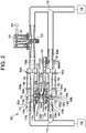
- FIGS. 1 and 2 illustrate an embodiment of a dual aspirator system 100.
- the dual aspirator system 100 is typically part of an internal combustion engine system, for example, a vehicle's engine.
- the system 100 includes a pair of aspirators 102, 104 in parallel, each with a motive port 106a, 106b, a discharge port 108a, 108b and a suction inlets 110a, 110b.
- the aspirators 102, 104 are "T-shaped" aspirators, but the principles generally disclosed herein may similarly be applied to "circular suction port"/"cone-in-cone” aspirators.
- the motive ports 106a, 106b of both aspirators 102, 104 are in fluid communication with a high pressure source 112, for example the engine intake air cleaner or the compressor of a turbo charger of a vehicle.
- a multi-port junction 114 connects the motive ports 106a, 106b to the high pressure source 112.
- the discharge ports 108a, 108b of both aspirators 102, 104 are in fluid communication with a low pressure sink 116, for example an engine intake manifold downstream of the throttle of the vehicle engine, or the air cleaner box of a boosted engine.
- a multi-port junction 118 connects the discharge ports 108a, 108b to the low pressure sink 116.
- Each aspirator 102, 104 defines a conduit 150 that includes a Venturi gap 152 separating the conduit 150 into a converging section 154 that begins at or proximate the respective motive port 106a, 106b and a diverging section 156 that ends at or proximate to the respective discharge port 108a, 108b.
- Both the converging sections 154 and the diverging sections 156 define continuously, gradually tapering inner passageways that narrow as they approach their Venturi gap 152 and create a Venturi effect on the fluid as it flows through the aspirator.
- the motive outlets 142a, 142b and the discharge inlets 144a, 144b of the aspirators 102, 104 may be sized and shaped to produce the desired flow capacity and Venturi effect therethrough, for example as discussed in U.S. Pat. App. No. 14/294,727, filed June 3, 2014 .
- the motive outlet 142a and/or discharge inlet 144a of the aspirator 102 may be the same or different size and shape as the motive outlet 142b and/or the discharge inlet 144b of aspirator 104 to provide different motive flow capacities for the respective aspirators 102, 104, and in turn to yield different potential combinations of motive flow rates through the system 100.
- the Venturi gap 152 and the motive outlet 142a and the discharge inlet 144a of the first aspirator 102 are sized and shaped to provide the aspirator with an overall lower suction flow than the second aspirator, which is designed to provide a higher overall suction flow.
- the opposite may be true, where the second aspirator 104 has an overall lower suction flow than the first aspirator 102.
- the suction inlets 110a, 110b of the aspirators 102, 104 are conjoined by a suction housing 122, having a suction port 124.
- the conjoined nature of the construction reduces the number of components, thus reducing materials and cost, and compacts the construction for space savings within an engine.
- both suction inlets 110a, 110b are in fluid communication with the suction port 124, which connects both aspirators 102, 104 to the same device 126, such as a device requiring a vacuum or a vacuum reservoir.
- the device requiring a vacuum 126 may be a vehicle brake boost canister, a fuel vapor recovery canister, any number of pneumatic operated/controlled valves, or the like.
- the aspirators 102, 104 may include check valves 128a, 128b positioned to prevent fluid from flowing from the suction inlets 110a, 110b toward the suction port 124.
- the check valves 128a, 128b may be positioned where the aspirators 102, 104 mate with the suction housing 122.
- the aspirators 102, 104 include valve seats 162a, 162b.
- Each valve seat 162a, 162b is defined by a continuous outer wall 164a, 164b, and, optionally, a wall 166a, 166b.
- a bore 168a, 168b is defined in each valve seat 162a, 162b to allow for air flow communication with the Venturi gap 152.
- Each valve seat 162a, 162b may include a plurality of radially spaced fingers 170 extending from a surface thereof. The radially spaced fingers 170 serve to support a seal member 172a, 172b.
- the suction housing 122 includes valve seats 174a, 174b defined by continuous outer walls of the suction housing 122 in a manner similar to that described above with respect to valve seats 162a, 162b.
- Valve seats 174a, 174b may each include a pin 176a, 176b extending toward the associated aspirator 102, 104.
- the pins 176a, 176b function as a guide for translation of the sealing members 172a, 172b within the cavities 178a, 178b defined by the mated valve seats 162a and 174a and defined by the mated valve seats 162b and 174b.
- each sealing member 172a, 172b includes a bore therethrough sized and positioned therein for receipt of the pin 176a, 176b within its respective cavity 178a, 178b.
- One or both of the aspirators 102, 104 may further include a bypass port 130 (in the depicted embodiment, only aspirator 104), which may include a check valve 132. Also, one or more of the aspirators 102, 104 may include a sound attenuation unit.
- the first aspirator 102 includes a sound attenuating unit 160a and the second aspirator 104 includes a sound attenuating unit 160b.
- the sound attenuating units 160a, 160b are illustrated to have a construction generally similar to at least one embodiment described in U.S. Provisional Patent Application No. 61/913,756, filed December 9, 2013 and may have a construction similar to other applicable embodiments therefrom.
- An aspirator shut-off valve (“ASOV”) 120 is disposed between the discharge port 108a and the multi-port junction 118 of the aspirator 102 in FIGS. 1 and 2 .
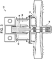
- the ASOV 120 may be a gate valve with a piston 121 controlling the movement of a gate mechanism 123 that is translatable between an open position and a closed position.
- the ASOV may be pneumatically actuated. In FIG. 2 , the ASOV 120 has its gate mechanism in a closed position where it blocks the flow of fluid between the discharge port 108a of the aspirator 102 and the low pressure sink 116.
- the ASOV 120 may be operatively connected to a computer or controller 125 in the vehicle to automatically control whether the ASOV 120 is in the open position or the closed position based on specific, pre-programmed system parameters.
- the ASOV 120 may be operatively connected to a gauge on the suction port 124 or another component or controller integrated into the system 100 or the vehicle to establish parameters to automatically and dynamically control the transition of the ASOV 120 between the open position and the closed position based on, for example, the suction pressure measured at the suction port 124.
- the ASOV 120 may be of the type shown and described in U.S. Pat. App. No. 14/154,268, filed January 14, 2014 .
- the ASOV may be an electromagnetically actuated ASOV 120', for example of the type shown and described in U.S. Prov. Pat. App. No. 61/872,402 .
- the ASOV 120' may incorporate a solenoid coil 180 and an armature 182 connectable to a valve mechanism 184 to form a sprung gate assembly 186 linearly movable to open and/or close the ASOV through the application of electric current.
- the ASOV may further alternately be an electromagnetically activated ASOV as shown and described in U.S. Prov. Pat. App. No. 61/914,658, filed on December 11, 2013 .
- the ASOV 120 may take any of a variety of other forms that enable the ASOV to selectively allow and/or block the flow of fluid through the system 100 as earlier described.
- a first flowpath 134 is defined between the high pressure source 112 and the low pressure sink 116 via the aspirator 104
- a second flowpath 136 is defined between the high pressure source 112 and the low pressure sink 116 via the aspirator 102 and controlled by the ASOV 120.
- the ASOV 120 may instead be positioned along the flowpath 136 before the aspirator 102, between the high pressure source 112 and the inlet of the motive port 106a (but downstream of the multi-port junction 114) with the same effect.
- first and second flowpaths 134, 136 While the system 100 disclosed herein is described with respect to the first and second flowpaths 134, 136, the system is not limited thereto and may incorporate additional aspirators and/or ASOVs, in series or in parallel. It is possible to include the first and second aspirators 102,104 as described herein in any flowpath between other components of an engine system to generate and/or control vacuum generation and use.
- the aspirators 102, 104 may be controlled to generate vacuum quickly and/or to generate a variable depth of vacuum, based on whether the ASOV 120 is in the open position or in the closed position.
- both flowpaths 134, 136 are active to harness the motive flow through both aspirators 102, 104 and both contribute to the creation of suction through the suction port 124 for the device requiring a vacuum 126.
- the motive flow from the high pressure source 112 to the low pressure sink 116 travels freely through both flowpaths 134, 136, as facilitated by the multi-port junctions 114, 118 which permit the initial bifurcation and subsequent recombination of the motive flow through the system 100.
- the aspirator system 100 may be used to form a simple, inexpensive variable flow rate control device for a vehicle engine by controlling the physical flow characteristics of the aspirators 102, 104 and by setting the operational parameters for opening and closing the ASOV 120.
- the conditions for automatically opening and closing the ASOV may be pre-programmed according to the desired motive mass flow rate through the system and/or the desired level of suction creation, thereby allowing the system to dynamically respond and adjust the motive mass flow rate as appropriate given the needs of the system 100.
- the system 100 enables variation in the motive mass flow rate while suction pressure is being continually generated by at least one of the plurality of aspirators.
Landscapes
- Engineering & Computer Science (AREA)
- Mechanical Engineering (AREA)
- General Engineering & Computer Science (AREA)
- Chemical & Material Sciences (AREA)
- Combustion & Propulsion (AREA)
- Transportation (AREA)
- Physics & Mathematics (AREA)
- Fluid Mechanics (AREA)
- Jet Pumps And Other Pumps (AREA)
- Braking Systems And Boosters (AREA)
- Valves And Accessory Devices For Braking Systems (AREA)
- External Artificial Organs (AREA)
- Motor Or Generator Cooling System (AREA)
Applications Claiming Priority (2)
| Application Number | Priority Date | Filing Date | Title |
|---|---|---|---|
| US14/463,200 US9669815B2 (en) | 2014-08-19 | 2014-08-19 | Dual aspirator system with aspirator shut-off valve |
| PCT/US2015/045264 WO2016028632A2 (en) | 2014-08-19 | 2015-08-14 | Dual aspirator system with aspirator shut-off valve |
Publications (3)
| Publication Number | Publication Date |
|---|---|
| EP3183449A2 EP3183449A2 (en) | 2017-06-28 |
| EP3183449A4 EP3183449A4 (en) | 2018-01-24 |
| EP3183449B1 true EP3183449B1 (en) | 2021-10-06 |
Family
ID=55347912
Family Applications (1)
| Application Number | Title | Priority Date | Filing Date |
|---|---|---|---|
| EP15833551.3A Not-in-force EP3183449B1 (en) | 2014-08-19 | 2015-08-14 | Dual aspirator system with aspirator shut-off valve |
Country Status (7)
| Country | Link |
|---|---|
| US (1) | US9669815B2 (enExample) |
| EP (1) | EP3183449B1 (enExample) |
| JP (1) | JP6810027B2 (enExample) |
| KR (1) | KR102217420B1 (enExample) |
| CN (1) | CN106662049B (enExample) |
| BR (1) | BR112017003358B1 (enExample) |
| WO (1) | WO2016028632A2 (enExample) |
Families Citing this family (4)
| Publication number | Priority date | Publication date | Assignee | Title |
|---|---|---|---|---|
| US9828953B2 (en) * | 2014-12-01 | 2017-11-28 | Dayco Ip Holdings, Llc | Evacuator system having multi-port evacuator |
| CN110382098B (zh) * | 2017-02-21 | 2022-05-17 | Dlh鲍尔斯公司 | 用于气体应用的真空生成器/放大器和制动助力器生成方法 |
| US10570829B2 (en) * | 2017-08-11 | 2020-02-25 | Ford Global Technologies, Llc | Methods and system for a common aspirator valve |
| DE102018211117B4 (de) * | 2018-07-05 | 2020-06-04 | Audi Ag | Unterdruckbereitstellungseinrichtung für eine Antriebseinrichtung, Verfahren zum Betreiben einer Unterdruckbereitstellungseinrichtung sowie Antriebseinrichtung für ein Kraftfahrzeug |
Family Cites Families (41)
| Publication number | Priority date | Publication date | Assignee | Title |
|---|---|---|---|---|
| US1845969A (en) | 1928-04-02 | 1932-02-16 | Trico Products Corp | Suction augmenting device |
| US2905268A (en) | 1956-10-29 | 1959-09-22 | Gen Motors Corp | Cleaner silencer assembly |
| US3234932A (en) | 1960-09-19 | 1966-02-15 | Forrest M Bird | Respirator |
| GB1195060A (en) | 1966-10-05 | 1970-06-17 | Vergaser Ges M B H & Co K G De | Improvements in Induction Systems for Internal Combustion Engines. |
| US3635601A (en) * | 1970-08-10 | 1972-01-18 | Economics Lab | Fail-safe multiple product aspirator |
| US3754841A (en) | 1971-05-14 | 1973-08-28 | Bendix Corp | Vacuum intensified brake booster system |
| US3698510A (en) | 1971-08-04 | 1972-10-17 | Blatt Leland F | Safety silencer air nozzle |
| DE2717685C3 (de) | 1977-04-21 | 1981-04-02 | Audi Nsu Auto Union Ag, 7107 Neckarsulm | Brennkraftmaschine für Kraftfahrzeuge |
| US4499034A (en) | 1982-09-02 | 1985-02-12 | The United States Of America As Represented By The United States Department Of Energy | Vortex-augmented cooling tower-windmill combination |
| US4554786A (en) | 1982-09-16 | 1985-11-26 | Nissin Kogyo Kabushiki Kaisha | Vacuum source device for vacuum booster for vehicles |
| AU545569B2 (en) | 1982-09-16 | 1985-07-18 | Honda Giken Kogyo Kabushiki Kaisha | Vacuum source device |
| US4519423A (en) | 1983-07-08 | 1985-05-28 | University Of Southern California | Mixing apparatus using a noncircular jet of small aspect ratio |
| US4610428A (en) | 1985-03-11 | 1986-09-09 | Borg-Warner Automotive, Inc. | Hermetically sealed electromagnetic solenoid valve |
| US4922965A (en) | 1989-02-22 | 1990-05-08 | Beta Mfg. Co. | Pneumatic solenoid valve |
| US5108266A (en) | 1991-05-29 | 1992-04-28 | Allied-Signal Inc. | Check valve with aspirating function |
| US5188141A (en) | 1991-12-03 | 1993-02-23 | Siemens Automotive Limited | Vacuum boost valve |
| US5291916A (en) | 1992-12-28 | 1994-03-08 | Excel Industries, Inc. | Check valve |
| DE4310761C2 (de) | 1993-04-01 | 1995-10-12 | Kayser A Gmbh & Co Kg | Strahlpumpe |
| WO1996026156A2 (en) | 1995-02-23 | 1996-08-29 | Ecolab Inc. | Apparatus and method for dispensing a viscous use solution |
| US5799831A (en) * | 1996-03-20 | 1998-09-01 | Ecolab Inc. | Dual aspirator |
| US6035881A (en) | 1997-05-15 | 2000-03-14 | Walter Alfmeier Ag Prazisions-Baugruppenelemente | Checkvalve unit |
| JP4643054B2 (ja) | 2001-04-19 | 2011-03-02 | 雅信 鯨田 | 文字及び顔文字から成る文章を入力する装置 |
| US6565361B2 (en) * | 2001-06-25 | 2003-05-20 | John Zink Company, Llc | Methods and apparatus for burning fuel with low NOx formation |
| JP4103038B2 (ja) * | 2001-10-31 | 2008-06-18 | 株式会社日立製作所 | 負圧供給装置 |
| JP3873742B2 (ja) * | 2001-12-28 | 2007-01-24 | いすゞ自動車株式会社 | 可変容量ターボチャージャの制御装置 |
| US20060016477A1 (en) | 2004-07-23 | 2006-01-26 | Algis Zaparackas | Vacuum enhancing check valve |
| SE528482C2 (sv) | 2005-05-25 | 2006-11-28 | Gm Global Tech Operations Inc | Bromsservosystem i en förbränningsmotor av typ Otto |
| KR100941808B1 (ko) * | 2008-07-11 | 2010-02-10 | 현대자동차주식회사 | 브레이크 부스터 부압 조절 장치 |
| US20110186151A1 (en) | 2010-02-04 | 2011-08-04 | Bernard Joseph Sparazynski | Check valve |
| US8757132B2 (en) * | 2010-03-08 | 2014-06-24 | Aisan Kogyo Kabushiki Kaisha | Fuel vapor processors |
| US8925520B2 (en) | 2010-03-10 | 2015-01-06 | Ford Global Technologies, Llc | Intake system including vacuum aspirator |
| US8960153B2 (en) | 2011-05-10 | 2015-02-24 | Ford Global Technologies, Llc | Method and system for controlling engine vacuum production |
| US10337628B2 (en) | 2012-02-20 | 2019-07-02 | Nyloncraft Incorporated | High mass flow check valve aspirator |
| US9022007B2 (en) | 2012-03-09 | 2015-05-05 | Ford Global Technologies, Llc | Throttle valve system for an engine |
| US8783231B2 (en) | 2012-03-12 | 2014-07-22 | Ford Global Technologies, Llc | Venturi for vapor purge |
| US9027536B2 (en) * | 2012-06-26 | 2015-05-12 | Ford Global Technologies, Llc | Crankcase ventilation and vacuum generation |
| DE102012015290A1 (de) | 2012-08-01 | 2014-02-06 | GM Global Technology Operations LLC (n. d. Gesetzen des Staates Delaware) | Verbrennungsmotor mit einem Vakuumerzeugungssystem für ein Kraftfahrzeug |
| US9074523B2 (en) * | 2012-11-16 | 2015-07-07 | Ford Global Technologies, Llc | Vacuum-actuated wastegate |
| JP2016527432A (ja) | 2013-07-17 | 2016-09-08 | デイコ アイピー ホールディングス, エルエルシーDayco Ip Holdings, Llc | アスピレータ及びエジェクタシステム |
| US9382882B2 (en) | 2013-10-29 | 2016-07-05 | Ford Global Technologies, Llc | Aspirator motive flow control for vacuum generation and compressor bypass |
| EP3090159B1 (en) * | 2013-12-11 | 2019-05-22 | Dayco IP Holdings, LLC | Turbocharger compressor recirculation system |
-
2014
- 2014-08-19 US US14/463,200 patent/US9669815B2/en not_active Expired - Fee Related
-
2015
- 2015-08-14 BR BR112017003358-5A patent/BR112017003358B1/pt not_active IP Right Cessation
- 2015-08-14 EP EP15833551.3A patent/EP3183449B1/en not_active Not-in-force
- 2015-08-14 KR KR1020177003856A patent/KR102217420B1/ko not_active Expired - Fee Related
- 2015-08-14 JP JP2017509669A patent/JP6810027B2/ja not_active Expired - Fee Related
- 2015-08-14 CN CN201580044469.8A patent/CN106662049B/zh active Active
- 2015-08-14 WO PCT/US2015/045264 patent/WO2016028632A2/en not_active Ceased
Also Published As
| Publication number | Publication date |
|---|---|
| WO2016028632A3 (en) | 2016-04-07 |
| US9669815B2 (en) | 2017-06-06 |
| BR112017003358B1 (pt) | 2022-09-27 |
| CN106662049A (zh) | 2017-05-10 |
| JP2017531119A (ja) | 2017-10-19 |
| JP6810027B2 (ja) | 2021-01-06 |
| US20160053727A1 (en) | 2016-02-25 |
| CN106662049B (zh) | 2018-04-17 |
| EP3183449A2 (en) | 2017-06-28 |
| KR102217420B1 (ko) | 2021-02-18 |
| BR112017003358A2 (pt) | 2018-06-26 |
| KR20170043524A (ko) | 2017-04-21 |
| WO2016028632A2 (en) | 2016-02-25 |
| EP3183449A4 (en) | 2018-01-24 |
Similar Documents
| Publication | Publication Date | Title |
|---|---|---|
| EP3090159B1 (en) | Turbocharger compressor recirculation system | |
| EP3094898B1 (en) | Flow control for aspirators producing vacuum using the venturi effect | |
| CN104334892B (zh) | 用于涡轮增压器的可变流量阀 | |
| CN204239101U (zh) | 发动机系统 | |
| EP3183449B1 (en) | Dual aspirator system with aspirator shut-off valve | |
| WO2017152043A1 (en) | Fluidic diode check valve | |
| EP3008324B1 (en) | Pneumatic compressor recirculation valve system for limitation of surge | |
| KR20080027934A (ko) | 차량 내에서 부분 진공을 형성하기 위한 장치 | |
| MX2008003800A (es) | Dispositivo de control de posicion de accionador que usa una servovalvula para evitar fallas. | |
| CN104487693B (zh) | 吸气器和排出器系统 | |
| RU64726U1 (ru) | Запорно-регулирующий клапан |
Legal Events
| Date | Code | Title | Description |
|---|---|---|---|
| STAA | Information on the status of an ep patent application or granted ep patent |
Free format text: STATUS: THE INTERNATIONAL PUBLICATION HAS BEEN MADE |
|
| PUAI | Public reference made under article 153(3) epc to a published international application that has entered the european phase |
Free format text: ORIGINAL CODE: 0009012 |
|
| STAA | Information on the status of an ep patent application or granted ep patent |
Free format text: STATUS: REQUEST FOR EXAMINATION WAS MADE |
|
| 17P | Request for examination filed |
Effective date: 20170308 |
|
| AK | Designated contracting states |
Kind code of ref document: A2 Designated state(s): AL AT BE BG CH CY CZ DE DK EE ES FI FR GB GR HR HU IE IS IT LI LT LU LV MC MK MT NL NO PL PT RO RS SE SI SK SM TR |
|
| AX | Request for extension of the european patent |
Extension state: BA ME |
|
| DAV | Request for validation of the european patent (deleted) | ||
| DAX | Request for extension of the european patent (deleted) | ||
| A4 | Supplementary search report drawn up and despatched |
Effective date: 20180104 |
|
| RIC1 | Information provided on ipc code assigned before grant |
Ipc: B60T 13/46 20060101ALI20171221BHEP Ipc: F02M 35/10 20060101AFI20171221BHEP Ipc: B60T 17/02 20060101ALI20171221BHEP |
|
| RIC1 | Information provided on ipc code assigned before grant |
Ipc: F02M 35/10 20060101AFI20210324BHEP Ipc: B60T 17/02 20060101ALI20210324BHEP Ipc: B60T 13/46 20060101ALI20210324BHEP Ipc: F04F 5/54 20060101ALI20210324BHEP |
|
| GRAP | Despatch of communication of intention to grant a patent |
Free format text: ORIGINAL CODE: EPIDOSNIGR1 |
|
| STAA | Information on the status of an ep patent application or granted ep patent |
Free format text: STATUS: GRANT OF PATENT IS INTENDED |
|
| INTG | Intention to grant announced |
Effective date: 20210430 |
|
| GRAS | Grant fee paid |
Free format text: ORIGINAL CODE: EPIDOSNIGR3 |
|
| GRAA | (expected) grant |
Free format text: ORIGINAL CODE: 0009210 |
|
| STAA | Information on the status of an ep patent application or granted ep patent |
Free format text: STATUS: THE PATENT HAS BEEN GRANTED |
|
| AK | Designated contracting states |
Kind code of ref document: B1 Designated state(s): AL AT BE BG CH CY CZ DE DK EE ES FI FR GB GR HR HU IE IS IT LI LT LU LV MC MK MT NL NO PL PT RO RS SE SI SK SM TR |
|
| REG | Reference to a national code |
Ref country code: GB Ref legal event code: FG4D |
|
| REG | Reference to a national code |
Ref country code: CH Ref legal event code: EP Ref country code: AT Ref legal event code: REF Ref document number: 1436435 Country of ref document: AT Kind code of ref document: T Effective date: 20211015 |
|
| REG | Reference to a national code |
Ref country code: IE Ref legal event code: FG4D |
|
| REG | Reference to a national code |
Ref country code: DE Ref legal event code: R096 Ref document number: 602015073989 Country of ref document: DE |
|
| REG | Reference to a national code |
Ref country code: LT Ref legal event code: MG9D |
|
| REG | Reference to a national code |
Ref country code: NL Ref legal event code: MP Effective date: 20211006 |
|
| REG | Reference to a national code |
Ref country code: AT Ref legal event code: MK05 Ref document number: 1436435 Country of ref document: AT Kind code of ref document: T Effective date: 20211006 |
|
| PG25 | Lapsed in a contracting state [announced via postgrant information from national office to epo] |
Ref country code: RS Free format text: LAPSE BECAUSE OF FAILURE TO SUBMIT A TRANSLATION OF THE DESCRIPTION OR TO PAY THE FEE WITHIN THE PRESCRIBED TIME-LIMIT Effective date: 20211006 Ref country code: LT Free format text: LAPSE BECAUSE OF FAILURE TO SUBMIT A TRANSLATION OF THE DESCRIPTION OR TO PAY THE FEE WITHIN THE PRESCRIBED TIME-LIMIT Effective date: 20211006 Ref country code: FI Free format text: LAPSE BECAUSE OF FAILURE TO SUBMIT A TRANSLATION OF THE DESCRIPTION OR TO PAY THE FEE WITHIN THE PRESCRIBED TIME-LIMIT Effective date: 20211006 Ref country code: BG Free format text: LAPSE BECAUSE OF FAILURE TO SUBMIT A TRANSLATION OF THE DESCRIPTION OR TO PAY THE FEE WITHIN THE PRESCRIBED TIME-LIMIT Effective date: 20220106 Ref country code: AT Free format text: LAPSE BECAUSE OF FAILURE TO SUBMIT A TRANSLATION OF THE DESCRIPTION OR TO PAY THE FEE WITHIN THE PRESCRIBED TIME-LIMIT Effective date: 20211006 |
|
| PG25 | Lapsed in a contracting state [announced via postgrant information from national office to epo] |
Ref country code: IS Free format text: LAPSE BECAUSE OF FAILURE TO SUBMIT A TRANSLATION OF THE DESCRIPTION OR TO PAY THE FEE WITHIN THE PRESCRIBED TIME-LIMIT Effective date: 20220206 Ref country code: SE Free format text: LAPSE BECAUSE OF FAILURE TO SUBMIT A TRANSLATION OF THE DESCRIPTION OR TO PAY THE FEE WITHIN THE PRESCRIBED TIME-LIMIT Effective date: 20211006 Ref country code: PT Free format text: LAPSE BECAUSE OF FAILURE TO SUBMIT A TRANSLATION OF THE DESCRIPTION OR TO PAY THE FEE WITHIN THE PRESCRIBED TIME-LIMIT Effective date: 20220207 Ref country code: PL Free format text: LAPSE BECAUSE OF FAILURE TO SUBMIT A TRANSLATION OF THE DESCRIPTION OR TO PAY THE FEE WITHIN THE PRESCRIBED TIME-LIMIT Effective date: 20211006 Ref country code: NO Free format text: LAPSE BECAUSE OF FAILURE TO SUBMIT A TRANSLATION OF THE DESCRIPTION OR TO PAY THE FEE WITHIN THE PRESCRIBED TIME-LIMIT Effective date: 20220106 Ref country code: NL Free format text: LAPSE BECAUSE OF FAILURE TO SUBMIT A TRANSLATION OF THE DESCRIPTION OR TO PAY THE FEE WITHIN THE PRESCRIBED TIME-LIMIT Effective date: 20211006 Ref country code: LV Free format text: LAPSE BECAUSE OF FAILURE TO SUBMIT A TRANSLATION OF THE DESCRIPTION OR TO PAY THE FEE WITHIN THE PRESCRIBED TIME-LIMIT Effective date: 20211006 Ref country code: HR Free format text: LAPSE BECAUSE OF FAILURE TO SUBMIT A TRANSLATION OF THE DESCRIPTION OR TO PAY THE FEE WITHIN THE PRESCRIBED TIME-LIMIT Effective date: 20211006 Ref country code: GR Free format text: LAPSE BECAUSE OF FAILURE TO SUBMIT A TRANSLATION OF THE DESCRIPTION OR TO PAY THE FEE WITHIN THE PRESCRIBED TIME-LIMIT Effective date: 20220107 Ref country code: ES Free format text: LAPSE BECAUSE OF FAILURE TO SUBMIT A TRANSLATION OF THE DESCRIPTION OR TO PAY THE FEE WITHIN THE PRESCRIBED TIME-LIMIT Effective date: 20211006 |
|
| REG | Reference to a national code |
Ref country code: DE Ref legal event code: R097 Ref document number: 602015073989 Country of ref document: DE |
|
| PG25 | Lapsed in a contracting state [announced via postgrant information from national office to epo] |
Ref country code: SM Free format text: LAPSE BECAUSE OF FAILURE TO SUBMIT A TRANSLATION OF THE DESCRIPTION OR TO PAY THE FEE WITHIN THE PRESCRIBED TIME-LIMIT Effective date: 20211006 Ref country code: SK Free format text: LAPSE BECAUSE OF FAILURE TO SUBMIT A TRANSLATION OF THE DESCRIPTION OR TO PAY THE FEE WITHIN THE PRESCRIBED TIME-LIMIT Effective date: 20211006 Ref country code: RO Free format text: LAPSE BECAUSE OF FAILURE TO SUBMIT A TRANSLATION OF THE DESCRIPTION OR TO PAY THE FEE WITHIN THE PRESCRIBED TIME-LIMIT Effective date: 20211006 Ref country code: EE Free format text: LAPSE BECAUSE OF FAILURE TO SUBMIT A TRANSLATION OF THE DESCRIPTION OR TO PAY THE FEE WITHIN THE PRESCRIBED TIME-LIMIT Effective date: 20211006 Ref country code: DK Free format text: LAPSE BECAUSE OF FAILURE TO SUBMIT A TRANSLATION OF THE DESCRIPTION OR TO PAY THE FEE WITHIN THE PRESCRIBED TIME-LIMIT Effective date: 20211006 Ref country code: CZ Free format text: LAPSE BECAUSE OF FAILURE TO SUBMIT A TRANSLATION OF THE DESCRIPTION OR TO PAY THE FEE WITHIN THE PRESCRIBED TIME-LIMIT Effective date: 20211006 |
|
| PLBE | No opposition filed within time limit |
Free format text: ORIGINAL CODE: 0009261 |
|
| STAA | Information on the status of an ep patent application or granted ep patent |
Free format text: STATUS: NO OPPOSITION FILED WITHIN TIME LIMIT |
|
| 26N | No opposition filed |
Effective date: 20220707 |
|
| PG25 | Lapsed in a contracting state [announced via postgrant information from national office to epo] |
Ref country code: AL Free format text: LAPSE BECAUSE OF FAILURE TO SUBMIT A TRANSLATION OF THE DESCRIPTION OR TO PAY THE FEE WITHIN THE PRESCRIBED TIME-LIMIT Effective date: 20211006 |
|
| PG25 | Lapsed in a contracting state [announced via postgrant information from national office to epo] |
Ref country code: SI Free format text: LAPSE BECAUSE OF FAILURE TO SUBMIT A TRANSLATION OF THE DESCRIPTION OR TO PAY THE FEE WITHIN THE PRESCRIBED TIME-LIMIT Effective date: 20211006 |
|
| PG25 | Lapsed in a contracting state [announced via postgrant information from national office to epo] |
Ref country code: MC Free format text: LAPSE BECAUSE OF FAILURE TO SUBMIT A TRANSLATION OF THE DESCRIPTION OR TO PAY THE FEE WITHIN THE PRESCRIBED TIME-LIMIT Effective date: 20211006 |
|
| REG | Reference to a national code |
Ref country code: CH Ref legal event code: PL |
|
| GBPC | Gb: european patent ceased through non-payment of renewal fee |
Effective date: 20220814 |
|
| PG25 | Lapsed in a contracting state [announced via postgrant information from national office to epo] |
Ref country code: LU Free format text: LAPSE BECAUSE OF NON-PAYMENT OF DUE FEES Effective date: 20220814 Ref country code: LI Free format text: LAPSE BECAUSE OF NON-PAYMENT OF DUE FEES Effective date: 20220831 Ref country code: CH Free format text: LAPSE BECAUSE OF NON-PAYMENT OF DUE FEES Effective date: 20220831 |
|
| REG | Reference to a national code |
Ref country code: BE Ref legal event code: MM Effective date: 20220831 |
|
| PG25 | Lapsed in a contracting state [announced via postgrant information from national office to epo] |
Ref country code: IT Free format text: LAPSE BECAUSE OF FAILURE TO SUBMIT A TRANSLATION OF THE DESCRIPTION OR TO PAY THE FEE WITHIN THE PRESCRIBED TIME-LIMIT Effective date: 20211006 |
|
| P01 | Opt-out of the competence of the unified patent court (upc) registered |
Effective date: 20230522 |
|
| PG25 | Lapsed in a contracting state [announced via postgrant information from national office to epo] |
Ref country code: IE Free format text: LAPSE BECAUSE OF NON-PAYMENT OF DUE FEES Effective date: 20220814 Ref country code: FR Free format text: LAPSE BECAUSE OF NON-PAYMENT OF DUE FEES Effective date: 20220831 |
|
| PG25 | Lapsed in a contracting state [announced via postgrant information from national office to epo] |
Ref country code: BE Free format text: LAPSE BECAUSE OF NON-PAYMENT OF DUE FEES Effective date: 20220831 |
|
| PG25 | Lapsed in a contracting state [announced via postgrant information from national office to epo] |
Ref country code: GB Free format text: LAPSE BECAUSE OF NON-PAYMENT OF DUE FEES Effective date: 20220814 |
|
| PG25 | Lapsed in a contracting state [announced via postgrant information from national office to epo] |
Ref country code: HU Free format text: LAPSE BECAUSE OF FAILURE TO SUBMIT A TRANSLATION OF THE DESCRIPTION OR TO PAY THE FEE WITHIN THE PRESCRIBED TIME-LIMIT; INVALID AB INITIO Effective date: 20150814 |
|
| PG25 | Lapsed in a contracting state [announced via postgrant information from national office to epo] |
Ref country code: CY Free format text: LAPSE BECAUSE OF FAILURE TO SUBMIT A TRANSLATION OF THE DESCRIPTION OR TO PAY THE FEE WITHIN THE PRESCRIBED TIME-LIMIT Effective date: 20211006 |
|
| PG25 | Lapsed in a contracting state [announced via postgrant information from national office to epo] |
Ref country code: MK Free format text: LAPSE BECAUSE OF FAILURE TO SUBMIT A TRANSLATION OF THE DESCRIPTION OR TO PAY THE FEE WITHIN THE PRESCRIBED TIME-LIMIT Effective date: 20211006 |
|
| PG25 | Lapsed in a contracting state [announced via postgrant information from national office to epo] |
Ref country code: TR Free format text: LAPSE BECAUSE OF FAILURE TO SUBMIT A TRANSLATION OF THE DESCRIPTION OR TO PAY THE FEE WITHIN THE PRESCRIBED TIME-LIMIT Effective date: 20211006 |
|
| PG25 | Lapsed in a contracting state [announced via postgrant information from national office to epo] |
Ref country code: MT Free format text: LAPSE BECAUSE OF FAILURE TO SUBMIT A TRANSLATION OF THE DESCRIPTION OR TO PAY THE FEE WITHIN THE PRESCRIBED TIME-LIMIT Effective date: 20211006 |
|
| PGFP | Annual fee paid to national office [announced via postgrant information from national office to epo] |
Ref country code: DE Payment date: 20240819 Year of fee payment: 10 |
|
| REG | Reference to a national code |
Ref country code: DE Ref legal event code: R119 Ref document number: 602015073989 Country of ref document: DE |