EP3183142B1 - Trim device for a motor vehicle, assembly, motor vehicle, and production method - Google Patents
Trim device for a motor vehicle, assembly, motor vehicle, and production method Download PDFInfo
- Publication number
- EP3183142B1 EP3183142B1 EP15750996.9A EP15750996A EP3183142B1 EP 3183142 B1 EP3183142 B1 EP 3183142B1 EP 15750996 A EP15750996 A EP 15750996A EP 3183142 B1 EP3183142 B1 EP 3183142B1
- Authority
- EP
- European Patent Office
- Prior art keywords
- movement elements
- trim
- damping
- ultrasonic sensor
- trim part
- Prior art date
- Legal status (The legal status is an assumption and is not a legal conclusion. Google has not performed a legal analysis and makes no representation as to the accuracy of the status listed.)
- Active
Links
- 238000004519 manufacturing process Methods 0.000 title claims description 5
- 238000013016 damping Methods 0.000 claims description 65
- 239000000463 material Substances 0.000 claims description 21
- 238000000034 method Methods 0.000 claims description 12
- 239000000919 ceramic Substances 0.000 claims description 11
- 229910052751 metal Inorganic materials 0.000 claims description 10
- 239000002184 metal Substances 0.000 claims description 10
- 238000002604 ultrasonography Methods 0.000 claims description 7
- 229920002323 Silicone foam Polymers 0.000 claims description 4
- 229920001971 elastomer Polymers 0.000 claims description 4
- 239000000806 elastomer Substances 0.000 claims description 4
- 239000013514 silicone foam Substances 0.000 claims description 4
- 238000003466 welding Methods 0.000 claims description 3
- 230000004308 accommodation Effects 0.000 claims 4
- 238000004026 adhesive bonding Methods 0.000 claims 1
- 238000005253 cladding Methods 0.000 description 19
- 239000012528 membrane Substances 0.000 description 12
- 239000000853 adhesive Substances 0.000 description 6
- 230000001070 adhesive effect Effects 0.000 description 6
- 230000002238 attenuated effect Effects 0.000 description 3
- 238000001746 injection moulding Methods 0.000 description 3
- 230000010355 oscillation Effects 0.000 description 3
- 230000005540 biological transmission Effects 0.000 description 2
- 238000004512 die casting Methods 0.000 description 2
- 238000012544 monitoring process Methods 0.000 description 2
- 229920001296 polysiloxane Polymers 0.000 description 2
- 229910052782 aluminium Inorganic materials 0.000 description 1
- XAGFODPZIPBFFR-UHFFFAOYSA-N aluminium Chemical compound [Al] XAGFODPZIPBFFR-UHFFFAOYSA-N 0.000 description 1
- 230000008878 coupling Effects 0.000 description 1
- 238000010168 coupling process Methods 0.000 description 1
- 238000005859 coupling reaction Methods 0.000 description 1
- 230000001419 dependent effect Effects 0.000 description 1
- 238000011161 development Methods 0.000 description 1
- 230000018109 developmental process Effects 0.000 description 1
- 238000009826 distribution Methods 0.000 description 1
- 239000007791 liquid phase Substances 0.000 description 1
- 230000003287 optical effect Effects 0.000 description 1
- 238000005476 soldering Methods 0.000 description 1
Images
Classifications
-
- B—PERFORMING OPERATIONS; TRANSPORTING
- B60—VEHICLES IN GENERAL
- B60R—VEHICLES, VEHICLE FITTINGS, OR VEHICLE PARTS, NOT OTHERWISE PROVIDED FOR
- B60R19/00—Wheel guards; Radiator guards, e.g. grilles; Obstruction removers; Fittings damping bouncing force in collisions
- B60R19/02—Bumpers, i.e. impact receiving or absorbing members for protecting vehicles or fending off blows from other vehicles or objects
- B60R19/48—Bumpers, i.e. impact receiving or absorbing members for protecting vehicles or fending off blows from other vehicles or objects combined with, or convertible into, other devices or objects, e.g. bumpers combined with road brushes, bumpers convertible into beds
- B60R19/483—Bumpers, i.e. impact receiving or absorbing members for protecting vehicles or fending off blows from other vehicles or objects combined with, or convertible into, other devices or objects, e.g. bumpers combined with road brushes, bumpers convertible into beds with obstacle sensors of electric or electronic type
-
- G—PHYSICS
- G01—MEASURING; TESTING
- G01S—RADIO DIRECTION-FINDING; RADIO NAVIGATION; DETERMINING DISTANCE OR VELOCITY BY USE OF RADIO WAVES; LOCATING OR PRESENCE-DETECTING BY USE OF THE REFLECTION OR RERADIATION OF RADIO WAVES; ANALOGOUS ARRANGEMENTS USING OTHER WAVES
- G01S15/00—Systems using the reflection or reradiation of acoustic waves, e.g. sonar systems
- G01S15/88—Sonar systems specially adapted for specific applications
- G01S15/93—Sonar systems specially adapted for specific applications for anti-collision purposes
- G01S15/931—Sonar systems specially adapted for specific applications for anti-collision purposes of land vehicles
-
- G—PHYSICS
- G01—MEASURING; TESTING
- G01S—RADIO DIRECTION-FINDING; RADIO NAVIGATION; DETERMINING DISTANCE OR VELOCITY BY USE OF RADIO WAVES; LOCATING OR PRESENCE-DETECTING BY USE OF THE REFLECTION OR RERADIATION OF RADIO WAVES; ANALOGOUS ARRANGEMENTS USING OTHER WAVES
- G01S7/00—Details of systems according to groups G01S13/00, G01S15/00, G01S17/00
- G01S7/52—Details of systems according to groups G01S13/00, G01S15/00, G01S17/00 of systems according to group G01S15/00
- G01S7/521—Constructional features
-
- G—PHYSICS
- G10—MUSICAL INSTRUMENTS; ACOUSTICS
- G10K—SOUND-PRODUCING DEVICES; METHODS OR DEVICES FOR PROTECTING AGAINST, OR FOR DAMPING, NOISE OR OTHER ACOUSTIC WAVES IN GENERAL; ACOUSTICS NOT OTHERWISE PROVIDED FOR
- G10K11/00—Methods or devices for transmitting, conducting or directing sound in general; Methods or devices for protecting against, or for damping, noise or other acoustic waves in general
- G10K11/002—Devices for damping, suppressing, obstructing or conducting sound in acoustic devices
-
- G—PHYSICS
- G10—MUSICAL INSTRUMENTS; ACOUSTICS
- G10K—SOUND-PRODUCING DEVICES; METHODS OR DEVICES FOR PROTECTING AGAINST, OR FOR DAMPING, NOISE OR OTHER ACOUSTIC WAVES IN GENERAL; ACOUSTICS NOT OTHERWISE PROVIDED FOR
- G10K9/00—Devices in which sound is produced by vibrating a diaphragm or analogous element, e.g. fog horns, vehicle hooters or buzzers
- G10K9/18—Details, e.g. bulbs, pumps, pistons, switches or casings
- G10K9/22—Mountings; Casings
-
- G—PHYSICS
- G01—MEASURING; TESTING
- G01S—RADIO DIRECTION-FINDING; RADIO NAVIGATION; DETERMINING DISTANCE OR VELOCITY BY USE OF RADIO WAVES; LOCATING OR PRESENCE-DETECTING BY USE OF THE REFLECTION OR RERADIATION OF RADIO WAVES; ANALOGOUS ARRANGEMENTS USING OTHER WAVES
- G01S15/00—Systems using the reflection or reradiation of acoustic waves, e.g. sonar systems
- G01S15/88—Sonar systems specially adapted for specific applications
- G01S15/93—Sonar systems specially adapted for specific applications for anti-collision purposes
- G01S15/931—Sonar systems specially adapted for specific applications for anti-collision purposes of land vehicles
- G01S2015/937—Sonar systems specially adapted for specific applications for anti-collision purposes of land vehicles sensor installation details
- G01S2015/938—Sonar systems specially adapted for specific applications for anti-collision purposes of land vehicles sensor installation details in the bumper area
Definitions
- the present invention relates to a cladding device for a motor vehicle, having a cladding part, which has a receiving region for arranging an ultrasonic sensor, and having a damping device for damping an oscillation generated as a result of an ultrasonic signal emitted by the ultrasonic sensor, wherein the damper surrounds the receiving region at least in regions.
- the invention also relates to an arrangement of such a covering device with an ultrasonic sensor.
- the present invention relates to a motor vehicle with at least one such arrangement.
- the present invention relates to a method for producing a cladding device for a motor vehicle.
- Ultrasonic sensors are installed in a known manner in the front area and in the rear area of the motor vehicle, in particular on bumpers. They are associated with driver assistance systems and provide information about the environment of the motor vehicle, namely the distances between the motor vehicle on the one hand and the obstacles located in its surroundings on the other hand.
- driver assistance systems may be, for example, parking assistance systems, blind spot monitoring systems, distance keeping systems, brake assist systems or the like.
- ultrasonic sensors are installed in bumpers uncovered and thus visible. This means that they are arranged in continuous recesses in the bumper and are visible on the outside. A pot-shaped membrane of the ultrasonic sensor extends through the continuous recess of the bumper, so that the front side of the membrane, via which ultrasonic waves are emitted and received, terminates flush with the outer surface of the bumper.
- These ultrasonic sensors have the distinct disadvantage that they are visibly arranged and thus affect the entire optical image of the motor vehicle.
- the present interest is directed to hidden or hidden built-ultrasonic sensors, which are not visible from the outside covered by the bumper when looking at the bumper.
- the ultrasonic sensor is located on a rear side of the bumper, so that the front side of the diaphragm - possibly via an additional mounting cover - is brought into contact with the rear side of the bumper.
- the ultrasonic signals are transmitted and received through the material of the bumper.
- an area of the bumper vibrates together with the diaphragm of the ultrasonic sensor. It is thus often necessary that this oscillating region of the bumper is limited by means of a damping device formed of ceramic.
- a damping device formed of ceramic, which has a passage opening through which the cup-shaped membrane of the ultrasonic sensor extends, so that the stiffening element is arranged around the membrane and also - possibly via a mounting lid - with the back of the bumper is brought into plant.
- a damping element is for example in the DE 10 2011 105 017 A1 described.
- the ultrasonic sensor must be mechanically fixed behind the bumper. This is necessary so that the ultrasonic sensor can transmit lossless through the bumper.
- the transmitting surface of the ultrasonic sensor - as the front surface of the membrane - mechanically fixed to the bumper are connected or formed with a lossless coupling element or mounting lid between the front of the membrane and the bumper.
- the abovementioned damping device with a large modulus of elasticity is required tightly around the transducer or around the diaphragm.
- Such a stiffening ring must be mechanically firmly connected to the bumper.
- the Ultrasonic sensor device has a stiffening element with a through opening through which the membrane extends.
- the stiffening element is porous and connected by its porous front cohesively with a mounting lid.
- the porous front has corresponding teeth or small recesses.
- the mounting lid is formed of a plastic material, which is molded onto the damping element.
- the damping element may comprise at least one recess
- the mounting cover may comprise at least one pin which engages in the associated recess of the damping element, wherein the at least one pin is formed by the injection molding of the plastic material.
- the US 20080089177 A1 discloses a cladding device for a motor vehicle according to the Oberberggrip of claim 1. It is an object of the present invention to provide a method, as the vibrations of an ultrasonic sensor, which is hidden behind a cowling of a motor vehicle, can be attenuated easier and cheaper. This object is achieved by a cladding device, by an arrangement, by a motor vehicle and by a method having the features according to the respective independent claims. Advantageous developments of the present invention are the subject of the dependent claims.
- a cladding device according to the invention for a motor vehicle comprises a cladding part, which has a receiving area for arranging an ultrasound sensor.
- the covering device comprises a damping device for damping a vibration generated as a result of an ultrasonic signal emitted by the ultrasonic sensor, wherein the damping device surrounds the receiving region at least in regions.
- the damping device has movement elements which are connected to the covering part, wherein a respective shape and / or a mechanical property of the movement elements is designed such that at least a part of the movement elements can be excited by the oscillation to move.
- the covering device comprises a covering part, which may be formed, for example, as a bumper or as a fender.
- the damping device comprises a plurality of movement elements, which are firmly connected to the covering part.
- the movement elements may be formed, for example, substantially cylindrical or conical.
- the movement elements may preferably each be designed in the manner of a villus.
- a respective shape and / or a mechanical property of the movement elements are designed such that at least a part of the movement elements is excited by the vibration to a movement.
- the geometric configuration and / or the mechanical properties of the respective movement elements can be designed such that the movement elements are excited to mechanical vibrations as a result of the vibration of the trim part.
- the resonance frequency of the movement elements can be designed such that they oscillate in resonance frequency as a result of the mechanical vibrations of the trim part. It can also be provided that the movement elements have different resonance frequencies.
- the vibration energy of the trim part is converted into a kinetic energy of the moving elements. In this way, the vibration of the trim panel can be attenuated us / or localized.
- the movement elements serve to dampen a mechanical vibration of the trim part.
- the movement elements can also serve to dampen structure-borne noise that propagates within the trim part.
- the movement elements of the damping device can serve to limit the range of vibration of the trim part, which is excited to vibrate by the ultrasonic signal.
- the damping device can limit the area of the trim part that vibrates together with a membrane of the ultrasonic sensor.
- the damping device can also serve to limit the area of the trim part in which ultrasonic waves are coupled in by the ultrasonic sensor.
- the damper may be used instead of a damper made of ceramic or comprising a ceramic ring.
- a cost-effective Damping device for damping vibrations of a trim part are provided.
- the movement elements are preferably connected to the covering part such that the movement elements extend substantially perpendicular to a surface of the covering part.
- the respective main extension direction of the movement elements extends substantially perpendicular to a main extension direction of the trim part. Movement elements, which are arranged substantially perpendicular to the cladding element, can be made simple and space saving.
- the movement elements are integrally connected to the covering part. In this way, a reliable connection between the moving elements and the cowling can be provided. Thus, it can be guaranteed that the movement elements remain reliably connected to the trim part during operation of the motor vehicle. Furthermore, such a material connection between the movement elements and the trim part can be provided easily and inexpensively.
- the movement elements are preferably connected to the trim part by an adhesive method and / or by friction welding.
- the moving elements may also be formed of a plastic.
- the moving elements can be friction welded to the cowling.
- the movement elements are injection-molded, for example, to the trim part. If the trim part is formed of a metal and the moving elements are also formed of a metal, the moving elements can be connected to the trim part, for example by means of a welding process or a soldering process. It can also be provided that the movement elements are connected by means of an adhesive method with the trim part.
- the movement elements are formed integrally with the trim part.
- the Paneling device be made by means of an injection molding process.
- both the movement elements and the trim part are made of metal, a corresponding die-casting method can be used.
- the movement elements can be integrated already in the production of the trim part.
- the movement elements are arranged unevenly distributed to each other. By the uneven distribution of the movement elements on the surface of the cladding element can be prevented, for example, that the movement elements are excited by the vibration of the trim part to the mechanical vibration. It is also conceivable that the individual movement elements have different shapes or dimensions. It can also be provided that the movement elements are made of different materials.
- the movement elements have different resonance frequencies. This can be achieved, for example, that the vibration of the trim part is also attenuated, if the vibration is not assigned to a single frequency, but a frequency range.
- the movement elements can also be arranged relative to one another in such a way that at least some of the movement elements touch each other during their movement. Thus, friction is generated between the moving elements which damps the vibration due to the ultrasonic signal.
- the movement elements are each formed from a plastic and / or a ceramic and / or a metal.
- all movement elements may be made of plastic or of a ceramic or of a metal.
- a part of the movement elements made of a plastic and / or a part of the movement elements made of a metal and / or a part of the movement elements are made of a ceramic.
- the different movement elements have different mechanical properties or vibration properties that react differently to the vibration of the trim part.
- the mechanical vibration of the trim part can be reliably damped or limited.
- the damping device has a cover element which is connected to the movement elements on a side of the movement elements opposite the covering part.
- a cover element which the Movement elements are arranged.
- Such a cover element, on which the movement elements are arranged may for example be made of plastic and manufactured by means of an injection molding process.
- a cover element, on which the movement elements are arranged be made of metal and manufactured by means of a die-casting process.
- the cover element, on which the movement elements are arranged is thus designed in the manner of a brush.
- a brush-shaped element can be connected, for example, a material fit with the trim part.
- an adhesive method can be used.
- the moving elements can be easily arranged on the cladding element.
- the damping device comprises a first annular element having a first diameter and a second annular element having a second diameter, which is larger in comparison to the first diameter, which are arranged concentrically to one another on the covering part, wherein the movement elements in a space between the first and the second annular element are arranged.
- the two annular elements, which are arranged concentrically to one another, can be molded onto the surface of the trim part, for example. Furthermore, it is also conceivable that the annular elements are integrated in the manufacturing process of the trim part.
- the receiving area for the ultrasonic sensor is arranged within the first annular element.
- the ultrasonic sensor is surrounded by the damping element.
- the damping device has a damping material for damping a movement of the movement elements, wherein the damping material is arranged at least partially between the movement elements.
- the damping material may surround the moving elements.
- the area between the two annular elements can be filled with the damping material.
- the movement elements are surrounded only to a predetermined height of the damping material.
- the damping material preferably comprises an elastomer, in particular a silicone foam.
- a silicone foam can be formed, for example, by arranging corresponding air bubbles within a silicone.
- the silicone may for example be provided in a liquid phase and distributed between the movement elements. There it can be cured accordingly.
- a damping material for damping the movement of the moving elements can be provided in a simple and cost-effective manner.
- An arrangement according to the invention for a motor vehicle comprises a cladding device according to the invention and the ultrasound sensor which is designed to emit and / or receive an ultrasound signal, the ultrasound sensor being connected to the cladding device in a materially bonded manner.
- the ultrasonic sensor is preferably arranged in the receiving region of the covering device.
- the ultrasonic sensor can be adhesively bonded to the trim part with a corresponding adhesive.
- the arrangement preferably comprises a housing in which the ultrasonic sensor and a decoupling element for decoupling the ultrasonic sensor from the housing are arranged.
- the housing may be formed, for example, as a corresponding mounting cover.
- the housing may be made of plastic, for example.
- a decoupling element is further provided, which serves, for example, to mechanically decouple the ultrasonic sensor from the housing.
- the decoupling element may be formed, for example, of ceramic or an elastomer.
- a motor vehicle according to the invention comprises at least one arrangement according to the invention.
- the motor vehicle is designed in particular as a passenger car.
- the arrangement may for example be associated with a driver assistance system of the motor vehicle.
- a driver assistance system can be, for example, a parking assistance system, a blind spot monitoring system, a distance keeping system, a brake assist system or the like.
- An inventive method is used to produce a covering device for a motor vehicle.
- a covering part which has a receiving region for arranging an ultrasonic sensor, is provided.
- a damping device for damping an oscillation generated as a result of an ultrasonic signal emitted by the ultrasonic sensor is provided, wherein the Damper surrounds the receiving area at least partially.
- the damping device has movement elements that are connected to the covering part, wherein a respective shape and / or a mechanical property of the movement elements is designed such that at least a part of the movement elements can be excited by the vibration to a movement.
- Fig. 1 shows an arrangement of one for a motor vehicle in a sectional side view.
- the arrangement 1 comprises an ultrasonic sensor 2.
- the ultrasonic sensor 2 serves to transmit an ultrasonic signal and / or to receive an ultrasonic signal.
- the ultrasonic sensor 2 comprises a membrane 3, which is cup-shaped and is preferably made of aluminum.
- the ultrasonic sensor 2 comprises an actuator, not shown here, which in particular comprises a piezoelectric element.
- the actuator serves to set the membrane 3 in mechanical vibrations.
- mechanical vibrations of the membrane 3 can be detected with the piezoelectric element.
- the arrangement 1 comprises a cladding device 4.
- the cladding device 4 in turn comprises a cladding part 5.
- the cladding part 5 may be formed for example by a bodywork component of a motor vehicle.
- the cowling 5 may be a bumper of a motor vehicle.
- the trim part 5 is a fender or part of a door of the motor vehicle.
- the trim part 5 may be formed of a plastic or of a metal.
- the ultrasonic sensor 2 is arranged on a rear side 6 of the covering part 5 in a receiving region 16 of the covering device 4.
- the back 6 of the trim part 5 is the part of the trim part 5 of the motor vehicle, which is not visible from the outside.
- the ultrasonic sensor 2 is connected with its front side, ie in the emitting direction of the ultrasonic signal, with the rear side 6 of the trim part 5.
- the ultrasonic sensor 2 is firmly bonded to the trim part 5, for example by means of an adhesive.
- ultrasonic signals are emitted by the ultrasonic sensor 2. These are passed through the cowling 5 through. In this case, the cowling 5 is excited to mechanical vibrations. It may also be the case that structure-borne noise propagates within the trim part 5.
- the trim device 4 has a damping device 7.
- the damping device 7 has a plurality of moving elements 8.
- the movement elements 8 may be formed in the manner of villi.
- the movement elements 8 are arranged on the back 6 of the trim part. In this case, the movement elements 8 are arranged such that the main extension direction of the movement elements 8 extends substantially perpendicular to the main extension direction of the trim part 5.
- the damping element 7 has a first annular element 9, which has a first diameter, and a second annular element 10, which has a second diameter, which is larger in comparison to the first diameter, on.
- the two annular elements 9 and 10 are arranged concentrically with each other. In the space between the first annular member 9 and the second annular member 10, the moving elements 8 are arranged.
- the movement elements 8 may be made of plastic, metal and / or ceramic, for example.
- the shape and / or the mechanical properties of the movement elements 8 can be chosen so that it is excited by the vibration of the trim part 5, which is due to the ultrasonic signal, which is emitted and / or received by the ultrasonic sensor 2 is caused to mechanical vibrations ,
- the moving elements 8 can be excited to vibrate at their resonant frequency.
- the vibration energy of the trim part 5 can be converted into the kinetic energy of the moving elements 8.
- the vibration of the trim part 5 can be damped and / or limited locally within the damping device 7.
- the movement elements 8 can have different resonance frequencies.
- the movement elements 8 may have different lengths.
- the movement elements 8 are arranged unevenly within the damping device 7. Thus, for example, a vibration of the cladding element 5 can be reliably damped.
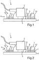
- Fig. 2 shows the arrangement according to Fig. 1 in a further embodiment.
- a damping material 11 is disposed between the moving elements 8.
- the damping material 11 is disposed in the space between the first annular member 9 and the second annular member 10.
- the damping material 11 may be formed, for example, by an elastomer, in particular a silicone foam.
- the damping material 11 extends only up to a predetermined height of the moving elements 8.
- the damping material 8 serves to damp a movement or a mechanical vibration of the moving elements eighth
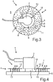
- Fig. 3 shows the arrangement 1 according to Fig. 2 in a top view. It can be seen in particular that the movement elements 8 are arranged distributed unevenly to each other within the damping device 7.
- Fig. 4 shows an arrangement 1 according to the invention.
- the damping device 4 comprises a cover element 12.
- the cover element 12 may be materially connected to the movement elements 8. It can also be provided that the cover element 12 is integrally formed with the movement elements 8.
- the cover element 12 and the movement elements 8 form a brush-shaped arrangement.
- the movement elements 8 are firmly bonded to the covering part 5, for example by means of an adhesive 13.
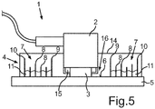
- Fig. 5 shows the arrangement according to Fig. 2 in a further embodiment.
- the arrangement 1 also comprises a housing 14.
- the housing 14 may be made of a plastic, for example.
- a decoupling element 15 is provided within the housing 14.
- the decoupling element 15 surrounds the diaphragm 3 concentrically in the present embodiment.
- the decoupling element 15 may be made of ceramic or a plastic, for example.
- the decoupling element 15 serves to decouple the ultrasonic sensor 2 or the membrane 3 mechanically from the housing 14.
Description
Die vorliegende Erfindung betrifft eine Verkleidungsvorrichtung für ein Kraftfahrzeug, mit einem Verkleidungsteil, welches einen Aufnahmebereich zum Anordnen eines Ultraschallsensors aufweist, und mit einer Dämpfungseinrichtung zum Dämpfen einer in Folge eines durch den Ultraschallsensor ausgesendeten Ultraschallsignals erzeugten Schwingung, wobei die Dämpfungseinrichtung den Aufnahmebereich zumindest bereichsweise umgibt. Die Erfindung betrifft außerdem eine Anordnung einer solchen Verkleidungsvorrichtung mit einem Ultraschallsensor. Zudem betrifft die vorliegende Erfindung ein Kraftfahrzeug mit zumindest einer solchen Anordnung. Schließlich betrifft die vorliegende Erfindung ein Verfahren zum Herstellen einer Verkleidungsvorrichtung für ein Kraftfahrzeug.The present invention relates to a cladding device for a motor vehicle, having a cladding part, which has a receiving region for arranging an ultrasonic sensor, and having a damping device for damping an oscillation generated as a result of an ultrasonic signal emitted by the ultrasonic sensor, wherein the damper surrounds the receiving region at least in regions. The invention also relates to an arrangement of such a covering device with an ultrasonic sensor. In addition, the present invention relates to a motor vehicle with at least one such arrangement. Finally, the present invention relates to a method for producing a cladding device for a motor vehicle.
Ultraschallsensoren sind in bekannter Weise im Frontbereich und im Heckbereich des Kraftfahrzeugs, insbesondere an Stoßfängern, verbaut. Sie sind Fahrerassistenzsystemen zugeordnet und liefern Informationen über die Umgebung des Kraftfahrzeugs, nämlich über die Abstände zwischen dem Kraftfahrzeug einerseits und den in seiner Umgebung befindlichen Hindernissen andererseits. Derartige Fahrerassistenzsysteme können beispielsweise Parkassistenzsysteme, Systeme zur Totwinkelüberwachung, Systeme zur Abstandshaltung, Bremsassistenzsysteme oder dergleichen sein.Ultrasonic sensors are installed in a known manner in the front area and in the rear area of the motor vehicle, in particular on bumpers. They are associated with driver assistance systems and provide information about the environment of the motor vehicle, namely the distances between the motor vehicle on the one hand and the obstacles located in its surroundings on the other hand. Such driver assistance systems may be, for example, parking assistance systems, blind spot monitoring systems, distance keeping systems, brake assist systems or the like.
Des Weiteren ist es bereits Stand der Technik, dass derartige Ultraschallsensoren in Stoßfängern unverdeckt und somit sichtbar verbaut werden. Dies bedeutet, dass sie in durchgängigen Aussparungen in dem Stoßfänger angeordnet sind und außenseitig sichtbar sind. Eine topfförmige Membran des Ultraschallsensors erstreckt sich hier durch die durchgängige Aussparung des Stoßfängers hindurch, sodass die Frontseite der Membran, über welche Ultraschallwellen ausgesendet und empfangen werden, bündig mit der äußeren Oberfläche des Stoßfängers abschließt. Diese Ultraschallsensoren haben jedoch den entscheidenden Nachteil, dass sie sichtbar angeordnet sind und somit das gesamte optische Bild des Kraftfahrzeugs beeinträchtigen.Furthermore, it is already state of the art that such ultrasonic sensors are installed in bumpers uncovered and thus visible. This means that they are arranged in continuous recesses in the bumper and are visible on the outside. A pot-shaped membrane of the ultrasonic sensor extends through the continuous recess of the bumper, so that the front side of the membrane, via which ultrasonic waves are emitted and received, terminates flush with the outer surface of the bumper. These ultrasonic sensors However, they have the distinct disadvantage that they are visibly arranged and thus affect the entire optical image of the motor vehicle.
Deshalb richtet sich das Interesse vorliegend auf verdeckt beziehungsweise versteckt verbaute Ultraschallsensoren, welche bei einer Betrachtung des Stoßfängers von außen nicht sichtbar durch den Stoßfänger abgedeckt sind. Hier befindet sich der Ultraschallsensor an einer Rückseite des Stoßfängers, sodass die Frontseite der Membran - gegebenenfalls über einen zusätzlichen Montagedeckel - mit der Rückseite des Stoßfängers in Anlage gebracht ist. Bei derartig verbauten Ultraschallsensoren direkt hinter dem Stoßfänger werden die Ultraschallsignale durch das Material des Stoßfängers hindurch gesendet und empfangen. Somit schwingt ein Bereich des Stoßfängers zusammen mit der Membran des Ultraschallsensors. Es ist somit oft erforderlich, dass dieser schwingende Bereich des Stoßfängers mit Hilfe einer aus Keramik gebildeten Dämpfungseinrichtung begrenzt wird. Es ist beispielsweise bekannt, eine aus Keramik gebildete Dämpfungseinrichtung bereitzustellen, welches eine Durchgangsöffnung aufweist, durch welche sich die topfförmige Membran des Ultraschallsensors hindurch erstreckt, sodass das Versteifungselement um die Membran herum angeordnet ist und außerdem - gegebenenfalls über einen Montagedeckel - mit der Rückseite des Stoßfängers in Anlage gebracht ist. Ein derartiges Dämpfungselement ist beispielsweise in der
Somit sind bei verdeckt hinter dem Stoßfänger verbauten Ultraschallsensoren jedoch wesentlich höhere Anforderungen an die Positionierung, die Klebung und die nun einzuhaltenden Toleranzen gegeben. Der Ultraschallsensor muss hinter dem Stoßfänger mechanisch fest angebracht werden. Dies ist erforderlich, damit der Ultraschallsensor verlustfrei durch den Stoßfänger senden kann. Um die Sende- und Empfangsverluste gering zu halten, muss die Sendefläche des Ultraschallsensors - als die Frontfläche der Membran - mechanisch fest mit dem Stoßfänger verbunden werden oder aber mit einem verlustfreien Koppelelement beziehungsweise Montagedeckel zwischen der Frontseite der Membran und dem Stoßfänger ausgebildet werden. Um die eingeleiteten Schwingungen lokal zu halten und die Sendecharakteristik zu beeinflussen, wird dann die oben genannte Dämpfungseinrichtung mit einem großen Elastizitätsmodul eng um den Wandler beziehungsweise um die Membran benötigt. Ein solcher Versteifungsring muss mechanisch fest mit dem Stoßfänger verbunden sein.However, in the case of obscured behind the bumper built-ultrasonic sensors, however, much higher requirements are placed on the positioning, bonding and tolerances now to be observed. The ultrasonic sensor must be mechanically fixed behind the bumper. This is necessary so that the ultrasonic sensor can transmit lossless through the bumper. In order to keep the transmission and reception losses low, the transmitting surface of the ultrasonic sensor - as the front surface of the membrane - mechanically fixed to the bumper are connected or formed with a lossless coupling element or mounting lid between the front of the membrane and the bumper. In order to keep the introduced vibrations locally and to influence the transmission characteristic, then the abovementioned damping device with a large modulus of elasticity is required tightly around the transducer or around the diaphragm. Such a stiffening ring must be mechanically firmly connected to the bumper.
Darüber hinaus beschreibt die
Ferner beschreibt die
Furthermore, the describes
Die
Diese Aufgabe wird erfindungsgemäß durch eine Verkleidungsvorrichtung, durch eine Anordnung, durch ein Kraftfahrzeug sowie durch ein Verfahren mit den Merkmalen gemäß den jeweiligen unabhängigen Patentansprüchen gelöst. Vorteilhafte Weiterbildungen der vorliegenden Erfindung sind Gegenstand der abhängigen Patentansprüche. Eine erfindungsgemäße Verkleidungsvorrichtung für ein Kraftfahrzeug umfasst ein Verkleidungsteil, welches einen Aufnahmebereich zum Anordnen eines Ultraschallsensors aufweist. Darüber hinaus umfasst die Verkleidungsvorrichtung eine Dämpfungseinrichtung zum Dämpfen einer in Folge eines durch den Ultraschallsensor ausgesendeten Ultraschallsignals erzeugten Schwingung, wobei die Dämpfungseinrichtung den Aufnahmebereich zumindest bereichsweise umgibt. Die Dämpfungseinrichtung weist Bewegungselemente auf, die mit dem Verkleidungsteil verbunden sind, wobei eine jeweilige Formgebung und/oder eine mechanische Eigenschaft der Bewegungselemente derart ausgelegt ist, dass zumindest ein Teil der Bewegungselemente durch die Schwingung zu einer Bewegung angregbar ist.
Die Verkleidungsvorrichtung umfasst ein Verkleidungsteil, das beispielsweise als Stoßfänger oder als Kotflügel ausgebildet sein kann. Darüber hinaus umfasst die Verkleidungsvorrichtung eine Dämpfungseinrichtung, welche zum Dämpfen von mechanischen Schwingungen dient. Diese mechanischen Schwingungen bilden sich beispielsweise dann aus, wenn von dem Ultraschallsensor, der mit der Verkleidungsvorrichtung mechanisch verbunden ist, Schallwellen in das Verkleidungsteil eingekoppelt werden. Diese Schallwellen können sich beispielsweise in Folge eines Ultraschallsignals ausbilden, welches der Ultraschallsensor aussendet. Die Dämpfungseinrichtung umfasst eine Mehrzahl von Bewegungselementen, die mit dem Verkleidungsteil fest verbunden sind. Die Bewegungselemente können beispielsweise im Wesentlichen zylinderförmig oder kegelförmig ausgebildet sein. Die Bewegungselemente können bevorzugt jeweils nach Art einer Zotte ausgebildet sein.The
This object is achieved by a cladding device, by an arrangement, by a motor vehicle and by a method having the features according to the respective independent claims. Advantageous developments of the present invention are the subject of the dependent claims. A cladding device according to the invention for a motor vehicle comprises a cladding part, which has a receiving area for arranging an ultrasound sensor. In addition, the covering device comprises a damping device for damping a vibration generated as a result of an ultrasonic signal emitted by the ultrasonic sensor, wherein the damping device surrounds the receiving region at least in regions. The damping device has movement elements which are connected to the covering part, wherein a respective shape and / or a mechanical property of the movement elements is designed such that at least a part of the movement elements can be excited by the oscillation to move.
The covering device comprises a covering part, which may be formed, for example, as a bumper or as a fender. In addition, the includes Paneling device a damping device which serves to dampen mechanical vibrations. These mechanical vibrations are formed, for example, when sound waves are coupled into the trim part of the ultrasonic sensor, which is mechanically connected to the cladding device. These sound waves can form, for example, as a result of an ultrasonic signal which the ultrasonic sensor emits. The damping device comprises a plurality of movement elements, which are firmly connected to the covering part. The movement elements may be formed, for example, substantially cylindrical or conical. The movement elements may preferably each be designed in the manner of a villus.
Hierbei sind eine jeweilige Form und/oder eine mechanische Eigenschaft der Bewegungselemente derart ausgestaltet, dass zumindest ein Teil der Bewegungselemente durch die Schwingung zu einer Bewegung angeregt ist. Die geometrische Ausgestaltung und/oder die mechanischen Eigenschaften der jeweiligen Bewegungselemente können derart gestaltet sein, dass die Bewegungselemente infolge der Schwingung des Verkleidungsteils zu mechanischen Schwingungen angeregt werden. Beispielsweise kann die Resonanzfrequenz der Bewegungselemente derart ausgelegt sein, dass diese in Folge der mechanischen Schwingungen des Verkleidungsteils in Resonanzfrequenz schwingen. Dabei kann es auch vorgesehen sein, dass die Bewegungselemente unterschiedliche Resonanzfrequenzen aufweisen. Somit wird die Schwingungsenergie des Verkleidungsteils in eine Bewegungsenergie der Bewegungselemente gewandelt. Auf diese Weise kann die Schwingung des Verkleidungsteils gedämpft uns/oder lokal begrenzt werden.Here, a respective shape and / or a mechanical property of the movement elements are designed such that at least a part of the movement elements is excited by the vibration to a movement. The geometric configuration and / or the mechanical properties of the respective movement elements can be designed such that the movement elements are excited to mechanical vibrations as a result of the vibration of the trim part. For example, the resonance frequency of the movement elements can be designed such that they oscillate in resonance frequency as a result of the mechanical vibrations of the trim part. It can also be provided that the movement elements have different resonance frequencies. Thus, the vibration energy of the trim part is converted into a kinetic energy of the moving elements. In this way, the vibration of the trim panel can be attenuated us / or localized.
Die Bewegungselemente dienen dazu, eine mechanische Schwingung des Verkleidungsteils zu dämpfen. Die Bewegungselemente können auch dazu dienen, Körperschall, der sich innerhalb des Verkleidungsteils ausbreitet, zu dämpfen. Weiterhin können die Bewegungselemente der Dämpfungseinrichtung dazu dienen, den Schwingungsbereich des Verkleidungsteils, das durch das Ultraschallsignal zu Schwingungen angeregt wird, zu begrenzen. Somit kann die Dämpfungseinrichtung den Bereich des Verkleidungsteils, der zusammen mit einer Membran des Ultraschallsensors schwingt, begrenzen. Die Dämpfungseinrichtung kann auch dazu dienen, den Bereich des Verkleidungsteils, in dem von dem Ultraschallsensor Ultraschallwellen eingekoppelt werden, zu begrenzen. Somit kann die Dämpfungseinrichtung anstelle einer Dämpfungseinrichtung, die aus Keramik gefertigt ist beziehungsweise die einen Keramikring umfasst, verwendet werden. Somit kann eine kostengünstige Dämpfungseinrichtung zum Dämpfen von Schwingungen eines Verkleidungsteils bereitgestellt werden.The movement elements serve to dampen a mechanical vibration of the trim part. The movement elements can also serve to dampen structure-borne noise that propagates within the trim part. Furthermore, the movement elements of the damping device can serve to limit the range of vibration of the trim part, which is excited to vibrate by the ultrasonic signal. Thus, the damping device can limit the area of the trim part that vibrates together with a membrane of the ultrasonic sensor. The damping device can also serve to limit the area of the trim part in which ultrasonic waves are coupled in by the ultrasonic sensor. Thus, the damper may be used instead of a damper made of ceramic or comprising a ceramic ring. Thus, a cost-effective Damping device for damping vibrations of a trim part are provided.
Bevorzugt sind die Bewegungselemente derart mit dem Verkleidungsteil verbunden, dass sich die Bewegungselemente im Wesentlichen senkrecht zu einer Oberfläche des Verkleidungsteils erstrecken. Mit anderen Worten verläuft die jeweilige Haupterstreckungsrichtung der Bewegungselemente im Wesentlichen senkrecht zu einer Haupterstreckungsrichtung des Verkleidungsteils. Bewegungselemente, die sich im Wesentlichen senkrecht zu dem Verkleidungselement angeordnet sind, können einfach und Bauraum sparend hergestellt werden.The movement elements are preferably connected to the covering part such that the movement elements extend substantially perpendicular to a surface of the covering part. In other words, the respective main extension direction of the movement elements extends substantially perpendicular to a main extension direction of the trim part. Movement elements, which are arranged substantially perpendicular to the cladding element, can be made simple and space saving.
In einer Ausführungsform sind die Bewegungselemente stoffschlüssig mit dem Verkleidungsteil verbunden. Auf diese Weise kann eine zuverlässige Verbindung zwischen den Bewegungselementen und dem Verkleidungsteil bereitgestellt werden. Somit kann garantiert werden, dass die Bewegungselemente im Betrieb des Kraftfahrzeugs zuverlässig mit dem Verkleidungsteil verbunden bleiben. Weiterhin kann eine derartige stoffschlüssige Verbindung zwischen den Bewegungselementen und dem Verkleidungsteil einfach und kostengünstig bereitgestellt werden.In one embodiment, the movement elements are integrally connected to the covering part. In this way, a reliable connection between the moving elements and the cowling can be provided. Thus, it can be guaranteed that the movement elements remain reliably connected to the trim part during operation of the motor vehicle. Furthermore, such a material connection between the movement elements and the trim part can be provided easily and inexpensively.
Bevorzugt sind die Bewegungselementen durch ein Klebeverfahren und/oder durch Reibschweißen mit dem Verkleidungsteil verbunden. Falls das Verkleidungsteil beispielsweise ein Stoßfänger ist, der aus Kunststoff gebildet ist, können die Bewegungselemente ebenfalls aus einem Kunststoff gebildet sein. In diesem Fall können die Bewegungselemente mittels Reibschweißen mit dem Verkleidungsteil verbunden werden. Weiterhin kann es vorgesehen sein, dass die Bewegungselemente beispielsweise an das Verkleidungsteil angespritzt sind. Falls das Verkleidungsteil aus einem Metall gebildet ist und die Bewegungselemente ebenfalls aus einem Metall gebildet sind, können die Bewegungselemente beispielsweise mittels eines Schweißverfahrens oder eines Lötverfahrens mit dem Verkleidungsteil verbunden werden. Es kann auch vorgesehen sein, dass die Bewegungselemente mittels eines Klebeverfahrens mit dem Verkleidungsteil verbunden werden. Somit kann eine zuverlässige und kostengünstige Verbindung zwischen den Bewegungselementen und dem Verkleidungsteil bereitgestellt werden.The movement elements are preferably connected to the trim part by an adhesive method and / or by friction welding. For example, if the cowling is a bumper made of plastic, the moving elements may also be formed of a plastic. In this case, the moving elements can be friction welded to the cowling. Furthermore, it can be provided that the movement elements are injection-molded, for example, to the trim part. If the trim part is formed of a metal and the moving elements are also formed of a metal, the moving elements can be connected to the trim part, for example by means of a welding process or a soldering process. It can also be provided that the movement elements are connected by means of an adhesive method with the trim part. Thus, a reliable and inexpensive connection between the moving elements and the cowling can be provided.
In einer weiteren Ausführungsform ist es vorgesehen, dass die Bewegungselemente einteilig mit dem Verkleidungsteil ausgebildet sind. Für den Fall, dass die Bewegungselemente und das Verkleidungsteil aus Kunststoff gefertigt sind, kann die Verkleidungsvorrichtung mittels eines Spritzgussverfahrens hergestellt sein. Für den Fall, dass sowohl die Bewegungselemente als auch das Verkleidungsteil aus Metall gefertigt sind, kann ein entsprechendes Druckgussverfahren verwendet werden. Somit können die Bewegungselemente bereits bei der Fertigung des Verkleidungsteils integriert werden.
In einer bevorzugten Ausführungsform sind die Bewegungselemente ungleichmäßig verteilt zueinander angeordnet. Durch die ungleichmäßige Verteilung der Bewegungselemente auf der Oberfläche des Verkleidungselements kann beispielsweise verhindert werden, dass die Bewegungselemente durch die Schwingung des Verkleidungsteils zu der mechanischen Schwingung angeregt werden. Dabei ist es auch denkbar, dass die einzelnen Bewegungselemente unterschiedliche Formgebungen beziehungsweise Abmessungen aufweisen. Es kann auch vorgesehen sein, dass die Bewegungselemente aus unterschiedlichen Materialien gefertigt sind. Somit weisen beispielsweise die Bewegungselemente unterschiedliche Resonanzfrequenzen auf. Damit kann beispielsweise erreicht werden, dass die Schwingung des Verkleidungsteils auch gedämpft wird, falls die Schwingung nicht einer einzelnen Frequenz, sondern einem Frequenzbereich zugeordnet ist. Die Bewegungselemente können auch derart zueinander angeordnet sein, dass sich zumindest einige der Bewegungselemente bei ihrer Bewegung berühren. Somit wird Reibung zwischen den Bewegungselemente erzeugt, welche die Schwingung in Folge des Ultraschallsignals dämpft.In a further embodiment, it is provided that the movement elements are formed integrally with the trim part. In the event that the moving elements and the cowling are made of plastic, the Paneling device be made by means of an injection molding process. In the event that both the movement elements and the trim part are made of metal, a corresponding die-casting method can be used. Thus, the movement elements can be integrated already in the production of the trim part.
In a preferred embodiment, the movement elements are arranged unevenly distributed to each other. By the uneven distribution of the movement elements on the surface of the cladding element can be prevented, for example, that the movement elements are excited by the vibration of the trim part to the mechanical vibration. It is also conceivable that the individual movement elements have different shapes or dimensions. It can also be provided that the movement elements are made of different materials. Thus, for example, the movement elements have different resonance frequencies. This can be achieved, for example, that the vibration of the trim part is also attenuated, if the vibration is not assigned to a single frequency, but a frequency range. The movement elements can also be arranged relative to one another in such a way that at least some of the movement elements touch each other during their movement. Thus, friction is generated between the moving elements which damps the vibration due to the ultrasonic signal.
In einer weiteren Ausgestaltung sind die Bewegungselemente jeweils aus einem Kunststoff und/oder aus einer Keramik und/oder aus einem Metall gebildet. Beispielsweise können jeweils alle Bewegungselemente aus Kunststoff oder aus einer Keramik oder aus einem Metall gebildet sein. Es ist auch denkbar, dass ein Teil der Bewegungselemente aus einem Kunststoff und/oder ein Teil der Bewegungselemente aus einem Metall und/oder ein Teil der Bewegungselemente aus einer Keramik gefertigt sind. Somit kann beispielsweise erreicht werden, dass die unterschiedlichen Bewegungselemente unterschiedliche mechanische Eigenschaften beziehungsweise Schwingungseigenschaften aufweisen, die unterschiedlich auf die Schwingung des Verkleidungsteils reagieren. Somit kann die mechanische Schwingung des Verkleidungsteils zuverlässig gedämpft bzw. begrenzt werden.In a further embodiment, the movement elements are each formed from a plastic and / or a ceramic and / or a metal. For example, in each case all movement elements may be made of plastic or of a ceramic or of a metal. It is also conceivable that a part of the movement elements made of a plastic and / or a part of the movement elements made of a metal and / or a part of the movement elements are made of a ceramic. Thus, it can be achieved, for example, that the different movement elements have different mechanical properties or vibration properties that react differently to the vibration of the trim part. Thus, the mechanical vibration of the trim part can be reliably damped or limited.
gemäß der Erfindung weist die Dämpfungseinrichtung ein Deckelelement auf, das mit den Bewegungselementen auf einer dem Verkleidungsteil gegenüberliegenden Seite der Bewegungselemente verbunden ist. Somit kann beispielsweise zunächst das Deckelelement gefertigt werden, an dem die Bewegungselemente angeordnet sind. Ein derartiges Deckelelement, an dem die Bewegungselemente angeordnet sind, kann beispielsweise aus Kunststoff gefertigt sein und mittels eins Spritzgussverfahrens hergestellt sein. Alternativ dazu kann ein derartiges Deckelelement, an dem die Bewegungselemente angeordnet sind, aus Metall gefertigt sein und mittels eines Druckgussverfahrens hergestellt sein. Das Deckelelement, an dem die Bewegungselemente angeordnet sind, ist somit nach Art einer Bürste ausgebildet. Ein derartiges bürstenförmiges Element kann beispielsweise stoffschlüssig mit dem Verkleidungsteil verbunden werden. Hierzu kann ein Klebeverfahren verwendet werden. Somit können die Bewegungselemente auf einfache Weise an dem Verkleidungselement angeordnet werden.According to the invention, the damping device has a cover element which is connected to the movement elements on a side of the movement elements opposite the covering part. Thus, for example, first the cover element can be manufactured, on which the Movement elements are arranged. Such a cover element, on which the movement elements are arranged, may for example be made of plastic and manufactured by means of an injection molding process. Alternatively, such a cover element, on which the movement elements are arranged, be made of metal and manufactured by means of a die-casting process. The cover element, on which the movement elements are arranged, is thus designed in the manner of a brush. Such a brush-shaped element can be connected, for example, a material fit with the trim part. For this purpose, an adhesive method can be used. Thus, the moving elements can be easily arranged on the cladding element.
In einer weiteren Ausführungsform weist die Dämpfungseinrichtung ein erstes ringförmiges Element mit einem ersten Durchmesser und ein zweites ringförmiges Element mit einem im Vergleich zum ersten Durchmesser größeren, zweiten Durchmesser, die konzentrisch zueinander auf dem Verkleidungsteil angeordnet sind, auf, wobei die Bewegungselemente in einem Zwischenraum zwischen dem ersten und dem zweiten ringförmigen Element angeordnet sind. Die beiden ringförmigen Elemente, die konzentrisch zueinander angeordnet sind, können beispielsweise an die Oberfläche des Verkleidungsteils angespritzt sein. Weiterhin ist es auch denkbar, dass die ringförmigen Elemente bei dem Herstellungsverfahren des Verkleidungsteils integriert werden. Innerhalb des ersten ringförmigen Elements ist der Aufnahmebereich für den Ultraschallsensor angeordnet. Somit wird der Ultraschallsensor von dem Dämpfungselement umgeben.In a further embodiment, the damping device comprises a first annular element having a first diameter and a second annular element having a second diameter, which is larger in comparison to the first diameter, which are arranged concentrically to one another on the covering part, wherein the movement elements in a space between the first and the second annular element are arranged. The two annular elements, which are arranged concentrically to one another, can be molded onto the surface of the trim part, for example. Furthermore, it is also conceivable that the annular elements are integrated in the manufacturing process of the trim part. Within the first annular element, the receiving area for the ultrasonic sensor is arranged. Thus, the ultrasonic sensor is surrounded by the damping element.
In einer bevorzugten Ausführungsform weist die Dämpfungseinrichtung ein Dämpfungsmaterial zum Dämpfen einer Bewegung der Bewegungselemente auf, wobei das Dämpfungsmaterial zumindest bereichsweise zwischen den Bewegungselementen angeordnet ist. Beispielsweise kann das Dämpfungsmaterial die Bewegungselemente umgeben. Dabei kann beispielsweise der Bereich zwischen den beiden ringförmigen Elementen mit dem Dämpfungsmaterial aufgefüllt sein. Dabei ist es auch denkbar, dass die Bewegungselemente nur zu einer vorbestimmten Höhe von dem Dämpfungsmaterial umgeben sind. Wenn die Bewegungselemente infolge der Schwingung des Verkleidungsteils zu Schwingungen angeregt werden, kann die jeweilige Schwingung der Bewegungselemente durch das Dämpfungselement gedämpft werden. Somit kann die Schwingung des Verkleidungsteils zuverlässig gedämpft werden.In a preferred embodiment, the damping device has a damping material for damping a movement of the movement elements, wherein the damping material is arranged at least partially between the movement elements. For example, the damping material may surround the moving elements. In this case, for example, the area between the two annular elements can be filled with the damping material. It is also conceivable that the movement elements are surrounded only to a predetermined height of the damping material. When the moving elements are excited to vibrate due to the vibration of the cowling, the respective vibration of the moving elements can be damped by the cushioning member. Thus, the vibration of the trim part can be reliably damped.
Bevorzugt umfasst das Dämpfungsmaterial ein Elastomer, insbesondere einen Silikonschaum. Ein derartiger Silikonschaum kann beispielsweise dadurch gebildet werden, dass entsprechende Luftblasen innerhalb eines Silikons angeordnet sind. Das Silikon kann beispielsweise in einer flüssigen Phase bereitgestellt werden und zwischen die Bewegungselemente verteilt werden. Dort kann es entsprechend ausgehärtet werden. Somit kann auf einfache und kostengünstige Weise ein Dämpfungsmaterial zum Dämpfen der Bewegung der Bewegungselemente bereitgestellt werden.The damping material preferably comprises an elastomer, in particular a silicone foam. Such a silicone foam can be formed, for example, by arranging corresponding air bubbles within a silicone. The silicone may for example be provided in a liquid phase and distributed between the movement elements. There it can be cured accordingly. Thus, a damping material for damping the movement of the moving elements can be provided in a simple and cost-effective manner.
Eine erfindungsgemäße Anordnung für ein Kraftfahrzeug umfasst eine erfindungsgemäße Verkleidungsvorrichtung und den Ultraschallsensor, welcher zum Aussenden und/oder Empfangen eines Ultraschallsignals ausgelegt ist, wobei der Ultraschallsensor stoffschlüssig mit der Verkleidungsvorrichtung verbunden ist. Dabei ist der Ultraschallsensor bevorzugt in dem Aufnahmebereich der Verkleidungsvorrichtung angeordnet. Insbesondere kann der Ultraschallsensor mit einem entsprechenden Klebstoff mit dem Verkleidungsteil stoffschlüssig verbunden sein.An arrangement according to the invention for a motor vehicle comprises a cladding device according to the invention and the ultrasound sensor which is designed to emit and / or receive an ultrasound signal, the ultrasound sensor being connected to the cladding device in a materially bonded manner. In this case, the ultrasonic sensor is preferably arranged in the receiving region of the covering device. In particular, the ultrasonic sensor can be adhesively bonded to the trim part with a corresponding adhesive.
Bevorzugt umfasst die Anordnung ein Gehäuse, in welchem der Ultraschallsensor und ein Entkopplungselement zum Entkoppeln des Ultraschallsensors von dem Gehäuse angeordnet sind. Das Gehäuse kann beispielsweise als entsprechender Montagedeckel ausgebildet sein. Das Gehäuse kann beispielsweise aus Kunststoff gefertigt sein. In dem Gehäuse ist weiterhin ein Entkopplungselement vorgesehen, das beispielsweise dazu dient, den Ultraschallsensor von dem Gehäuse mechanisch zu entkoppeln. Das Entkopplungselement kann beispielsweise aus Keramik oder einem Elastomer gebildet sein.The arrangement preferably comprises a housing in which the ultrasonic sensor and a decoupling element for decoupling the ultrasonic sensor from the housing are arranged. The housing may be formed, for example, as a corresponding mounting cover. The housing may be made of plastic, for example. In the housing, a decoupling element is further provided, which serves, for example, to mechanically decouple the ultrasonic sensor from the housing. The decoupling element may be formed, for example, of ceramic or an elastomer.
Ein erfindungsgemäßes Kraftfahrzeug umfasst zumindest eine erfindungsgemäße Anordnung. Das Kraftfahrzeug ist insbesondere als Personenkraftwagen ausgebildet. Die Anordnung kann beispielsweise einem Fahrerassistenzsystem des Kraftfahrzeugs zugeordnet sein. Ein solches Fahrerassistenzsystem kann beispielsweise ein Parkassistenzsystem, ein System zur Totwinkelüberwachung, ein System zur Abstandshaltung, ein Bremsassistenzsystem oder dergleichen sein.A motor vehicle according to the invention comprises at least one arrangement according to the invention. The motor vehicle is designed in particular as a passenger car. The arrangement may for example be associated with a driver assistance system of the motor vehicle. Such a driver assistance system can be, for example, a parking assistance system, a blind spot monitoring system, a distance keeping system, a brake assist system or the like.
Ein erfindungsgemäßes Verfahren dient zum Herstellen einer Verkleidungsvorrichtung für ein Kraftfahrzeug. Hierbei wird ein Verkleidungsteil, welches einen Aufnahmebereich zum Anordnen eines Ultraschallsensors aufweist, bereitgestellt. Zudem wird eine Dämpfungseinrichtung zum Dämpfen einer infolge eines durch den Ultraschallsensor ausgesendeten Ultraschallsignals erzeugten Schwingung bereitgestellt, wobei die Dämpfungseinrichtung den Aufnahmebereich zumindest bereichsweise umgibt. Die Dämpfungseinrichtung weist Bewegungselemente auf, die mit dem Verkleidungsteil verbunden werden, wobei eine jeweilige Formgebung und/oder eine mechanische Eigenschaft der Bewegungselemente derart ausgelegt wird, dass zumindest ein Teil der Bewegungselemente durch die Schwingung zu einer Bewegung anregbar ist.
Die mit Bezug auf die erfindungsgemäße Verkleidungsvorrichtung vorgestellten bevorzugten Ausführungsformen und deren Vorteile gelten entsprechend für die erfindungsgemäße Anordnung, das erfindungsgemäße Kraftfahrzeug sowie das erfindungsgemäße Verfahren.An inventive method is used to produce a covering device for a motor vehicle. In this case, a covering part, which has a receiving region for arranging an ultrasonic sensor, is provided. In addition, a damping device for damping an oscillation generated as a result of an ultrasonic signal emitted by the ultrasonic sensor is provided, wherein the Damper surrounds the receiving area at least partially. The damping device has movement elements that are connected to the covering part, wherein a respective shape and / or a mechanical property of the movement elements is designed such that at least a part of the movement elements can be excited by the vibration to a movement.
The preferred embodiments presented with reference to the cladding device according to the invention and their advantages apply correspondingly to the arrangement according to the invention, the motor vehicle according to the invention and the method according to the invention.
Die Erfindung wird nun anhand eines bevorzugten Ausführungsbeispiels sowie unter Bezugnahme auf die beigefügten Zeichnungen näher erläutert.The invention will now be described with reference to a preferred embodiment and with reference to the accompanying drawings.
Es zeigen:
- Fig. 1
- in schematischer Darstellung eine Anordnung für ein Kraftfahrzeug, welche eine Verkleidungsvorrichtung und einen Ultraschallsensor umfasst;
- Fig. 2
- die Anordnung gemäß
Fig. 1 in einer weiteren Ausführungsform; - Fig. 3
- die Anordnung gemäß
Fig. 2 in einer Draufsicht; - Fig. 4
- eine Anordnung gemäß der Erfindung; und
- Fig. 5
- die Anordnung gemäß
Fig. 2 in einer weiteren Ausführungsform.
- Fig. 1
- a schematic representation of an arrangement for a motor vehicle, which comprises a covering device and an ultrasonic sensor;
- Fig. 2
- the arrangement according to
Fig. 1 in a further embodiment; - Fig. 3
- the arrangement according to
Fig. 2 in a plan view; - Fig. 4
- an arrangement according to the invention; and
- Fig. 5
- the arrangement according to
Fig. 2 in a further embodiment.
Des Weiteren umfasst die Anordnung 1 eine Verkleidungsvorrichtung 4. Die Verkleidungsvorrichtung 4 umfasst wiederum ein Verkleidungsteil 5. Das Verkleidungsteil 5 kann beispielsweise durch ein Karosseriebauteil eines Kraftfahrzeugs gebildet sein. Beispielsweise kann das Verkleidungsteil 5 ein Stoßfänger eines Kraftfahrzeugs sein. Es ist auch denkbar, dass das Verkleidungsteil 5 ein Kotflügel oder ein Teil einer Tür des Kraftfahrzeugs ist. Das Verkleidungsteil 5 kann aus einem Kunststoff oder aus einem Metall gebildet sein.Furthermore, the
Der Ultraschallsensor 2 ist auf einer Rückseite 6 des Verkleidungsteils 5 in einem Aufnahmebereich 16 der Verkleidungsvorrichtung 4 angeordnet. Die Rückseite 6 des Verkleidungsteils 5 ist der Teil des Verkleidungsteils 5 des Kraftfahrzeugs, der von außen nicht sichtbar ist. Der Ultraschallsensor 2 ist mit seiner Frontseite, also in Aussenderichtung des Ultraschallsignals, mit der Rückseite 6 des Verkleidungsteils 5 verbunden. Insbesondere ist der Ultraschallsensor 2 stoffschlüssig, beispielsweise mittels eines Klebstoffs, mit dem Verkleidungsteil 5 verbunden. Bei Betrieb des Ultraschallsensors 2 werden von dem Ultraschallsensor 2 Ultraschallsignale ausgesendet. Diese werden durch das Verkleidungsteil 5 hindurch geleitet. Dabei wird das Verkleidungsteil 5 zu mechanischen Schwingungen angeregt. Es kann auch der Fall sein, dass sich Körperschall innerhalb des Verkleidungsteils 5 ausbreitet.The
Um die Schwingung des Verkleidungsteils 5 zu dämpfen, weist die Verkleidungsvorrichtung 4 eine Dämpfungseinrichtung 7 auf. Die Dämpfungseinrichtung 7 weist eine Mehrzahl von Bewegungselementen 8 auf. Die Bewegungselemente 8 können nach Art von Zotten ausgebildet sein. Die Bewegungselemente 8 sind auf der Rückseite 6 des Verkleidungsteils angeordnet. Dabei sind die Bewegungselemente 8 derart angeordnet, dass die Haupterstreckungsrichtung der Bewegungselemente 8 im Wesentlichen senkrecht zu der Haupterstreckungsrichtung des Verkleidungsteils 5 verläuft.In order to dampen the vibration of the
In dem vorliegenden Ausführungsbeispiel weist das Dämpfungselement 7 ein erstes ringförmiges Element 9, das einen ersten Durchmesser aufweist, und ein zweites ringförmiges Element 10, das einen im Vergleich zum ersten Durchmesser größeren zweiten Durchmesser aufweist, auf. Dabei sind die beiden ringförmigen Elemente 9 und 10 konzentrisch zueinander angeordnet. In dem Zwischenraum zwischen dem ersten ringförmigen Element 9 und dem zweiten ringförmigen Element 10 sind die Bewegungselemente 8 angeordnet.In the present embodiment, the damping
Die Bewegungselemente 8 können beispielsweise aus Kunststoff, aus Metall und/oder aus Keramik gefertigt sein. Die Formgebung und/oder die mechanischen Eigenschaften der Bewegungselemente 8 können so gewählt sein, dass diese durch die Schwingung des Verkleidungsteils 5, die infolge des Ultraschallsignals, das von dem Ultraschallsensor 2 ausgesendet und/oder empfangen wird, bewirkt wird, zu mechanischen Schwingungen angeregt wird. Beispielsweise können die Bewegungselemente 8 zur Schwingung in ihrer Resonanzfrequenz angeregt werden. Somit kann die Schwingungsenergie des Verkleidungsteils 5 in die Bewegungsenergie der Bewegungselemente 8 gewandelt werden. Somit kann die Schwingung des Verkleidungsteils 5 gedämpft und/oder lokal innerhalb der Dämpfungseinrichtung 7 begrenzt werden. Die Bewegungselemente 8 können dabei unterschiedliche Resonanzfrequenzen aufweisen. Beispielsweise können die Bewegungselemente 8 unterschiedliche Längen aufweisen. Insbesondere sind die Bewegungselemente 8 innerhalb der Dämpfungseinrichtung 7 ungleichmäßig angeordnet. Somit kann beispielsweise eine Schwingung des Verkleidungselements 5 zuverlässig gedämpft werden.The
Claims (14)
- Trim device (4) for a motor vehicle, having a trim part (5) which has an accommodation region (16) for the arrangement of an ultrasonic sensor (2), and having a damping apparatus (7) for damping a vibration generated as a result of an ultrasound signal emitted by the ultrasonic sensor (2), the damping apparatus (7) at least partly surrounding the accommodation region (16), the damping apparatus (7) having movement elements (8) which are connected to the trim part (5), a respective shape and/or a mechanical property of the movement elements (8) being designed such that at least some of the movement elements (8) can be excited to move by the vibration,
characterized in that the damping apparatus (7) has a cover element (12), which is connected to the movement elements (8) on a side of the movement elements (8) that is opposite the trim part (5). - Trim device (4) according to Claim 1,
characterized in that
the movement elements (8) are connected to the trim part (5) in such a way that the movement elements (8) extend substantially at right angles to the surface of the trim part (5). - Trim device (4) according to Claim 1 or 2,
characterized in that
the movement elements (8) are connected integrally to the trim part (5). - Trim device (4) according to Claim 3,
characterized in that
the movement elements (8) are connected to the trim part (5) by an adhesive bonding method and/or by frictional welding. - Trim device (4) according to Claim 1 or 2, characterized in that
the movement elements (8) are formed in one piece with the trim part (5). - Trim device (4) according to one of the preceding claims,
characterized in that
the movement elements (8) are arranged to be distributed non-uniformly relative to one another. - Trim device (4) according to one of the preceding claims
characterized in that
the movement elements (8) are each formed from a plastic and/or from a ceramic and/or from a metal. - Trim device (4) according to one of the preceding claims,
characterized in that
the damping apparatus (7) has a first annular element (9) with a first diameter and a second annular element (10) with a second diameter that is larger as compared with the first diameter, which are arranged concentrically relative to each other on the trim part (5), wherein the movement elements (8) are arranged in an interspace between the first and the second annular element (9, 10). - Trim device (4) according to one of the preceding claims,
characterized in that
the damping apparatus (7) has a damping material (11) for damping a movement of the movement elements (8), wherein the damping material (11) is at least partly arranged between the movement elements (8). - Trim device (4) according to Claim 9,
characterized in that
the damping material (11) comprises an elastomer, in particular a silicone foam. - Assembly (1) for a motor vehicle, having a trim device (4) according to one of the preceding claims and the ultrasonic sensor (2), which is designed to emit and/or receive an ultrasound signal, wherein the ultrasonic sensor (2) is connected integrally to the trim device (4).
- Assembly (1) according to Claim 11,
characterized in that
the assembly comprises a housing (14), in which the ultrasonic sensor (2) and a decoupling element (15) for decoupling the ultrasonic sensor (2) from the housing (14) are arranged. - Motor vehicle having at least one assembly (1) according to Claim 12.
- Method for producing a trim device (4) for a motor vehicle, in which a trim part (5) which has an accommodation region (16) for the arrangement of an ultrasonic sensor (2) is provided, and a damping apparatus (7) for damping a vibration generated as a result of an ultrasound signal emitted by the ultrasonic sensor (2) is provided, the damping apparatus (7) at least partly surrounding the accommodation region (16), the damping apparatus (7) having movement elements (8) which are connected to the trim part (5), a respective shape and/or a mechanical property of the movement elements (8) being designed such that at least some of the movement elements (8) can be excited to move by the vibration,
characterized in that the damping apparatus (7) has a cover element (12), which is connected to the movement elements (8) on a side of the movement elements (8) that is opposite the trim part (5).
Applications Claiming Priority (2)
| Application Number | Priority Date | Filing Date | Title |
|---|---|---|---|
| DE102014111947.9A DE102014111947A1 (en) | 2014-08-21 | 2014-08-21 | Paneling device for a motor vehicle, arrangement, motor vehicle and manufacturing method |
| PCT/EP2015/068657 WO2016026766A1 (en) | 2014-08-21 | 2015-08-13 | Trim device for a motor vehicle, assembly, motor vehicle, and production method |
Publications (2)
| Publication Number | Publication Date |
|---|---|
| EP3183142A1 EP3183142A1 (en) | 2017-06-28 |
| EP3183142B1 true EP3183142B1 (en) | 2018-09-26 |
Family
ID=53879502
Family Applications (1)
| Application Number | Title | Priority Date | Filing Date |
|---|---|---|---|
| EP15750996.9A Active EP3183142B1 (en) | 2014-08-21 | 2015-08-13 | Trim device for a motor vehicle, assembly, motor vehicle, and production method |
Country Status (3)
| Country | Link |
|---|---|
| EP (1) | EP3183142B1 (en) |
| DE (1) | DE102014111947A1 (en) |
| WO (1) | WO2016026766A1 (en) |
Families Citing this family (5)
| Publication number | Priority date | Publication date | Assignee | Title |
|---|---|---|---|---|
| DE102015116442A1 (en) | 2015-09-29 | 2017-03-30 | Valeo Schalter Und Sensoren Gmbh | Damping device for an outer part, arrangement with a damping device and motor vehicle |
| DE102016202307A1 (en) * | 2016-02-16 | 2017-08-17 | Robert Bosch Gmbh | Holder for a sensor |
| DE102017127587A1 (en) * | 2017-11-22 | 2019-05-23 | Valeo Schalter Und Sensoren Gmbh | Arrangement for a motor vehicle with an ultrasonic sensor and with a damping element, which has reinforcing elements and device |
| DE102018100594A1 (en) | 2018-01-12 | 2019-07-18 | Valeo Schalter Und Sensoren Gmbh | Ultrasonic sensor arrangement for a motor vehicle with elements for reducing the propagation of bending waves and associated production method |
| DE102018105267B3 (en) | 2018-03-07 | 2019-04-25 | Valeo Schalter Und Sensoren Gmbh | Damping element for an ultrasonic sensor |
Family Cites Families (4)
| Publication number | Priority date | Publication date | Assignee | Title |
|---|---|---|---|---|
| JP2007114182A (en) * | 2005-09-22 | 2007-05-10 | Denso Corp | Mounting structure of ultrasonic sensor |
| JP4917401B2 (en) * | 2006-10-05 | 2012-04-18 | 株式会社日本自動車部品総合研究所 | Obstacle detection device |
| DE102011105017A1 (en) | 2011-06-20 | 2012-12-20 | Valeo Schalter Und Sensoren Gmbh | Ultrasonic sensor device for a vehicle and arrangement with such an ultrasonic sensor device |
| DE102012106694A1 (en) | 2012-07-24 | 2014-02-13 | Valeo Schalter Und Sensoren Gmbh | An ultrasonic sensor device comprising a stiffening element and a mounting lid, an arrangement and a method for producing such an ultrasonic sensor device |
-
2014
- 2014-08-21 DE DE102014111947.9A patent/DE102014111947A1/en not_active Withdrawn
-
2015
- 2015-08-13 EP EP15750996.9A patent/EP3183142B1/en active Active
- 2015-08-13 WO PCT/EP2015/068657 patent/WO2016026766A1/en active Application Filing
Also Published As
| Publication number | Publication date |
|---|---|
| WO2016026766A1 (en) | 2016-02-25 |
| EP3183142A1 (en) | 2017-06-28 |
| DE102014111947A1 (en) | 2016-02-25 |
Similar Documents
| Publication | Publication Date | Title |
|---|---|---|
| EP3183142B1 (en) | Trim device for a motor vehicle, assembly, motor vehicle, and production method | |
| EP2559024B1 (en) | Method for driving an ultrasound sensor and ultrasound sensor | |
| EP2877873B1 (en) | Ultrasonic sensor arrangment comprising an ultrasonic sensor in the radiator grill, motor vehicle and corresponding method | |
| EP2877870B1 (en) | Ultrasonic sensor device having an improved decoupling ring and motor vehicle | |
| DE102006055168A1 (en) | The obstacle detection system | |
| DE102012208059A1 (en) | Sensor assembly for measuring distance in vehicle, has membrane, which is positively integrated as separate component or in form of fiber mat in support element, and damping material is applied on vibratable portion of membrane | |
| EP2660627B1 (en) | Sensor assembly comprising a flat vehicle component and an ultrasound sensor | |
| EP3012655B1 (en) | Ultrasound sensor device for a motor vehicle, assembly and motor vehicle | |
| EP3010651B1 (en) | Surroundings-sensing system having a modular ultrasonic transducer, and a motor vehicle having such a surroundings-sensing system | |
| EP2877990B1 (en) | Ultrasonic sensor device | |
| DE102009040374A1 (en) | Ultrasonic transducer for vehicle body, is provided with decoupling ring for damping vibrations between shielded conductive housing and vibration-generating membrane | |
| EP2909831A2 (en) | Ultrasonic sensor device having a stiffening unit, assembly, motor vehicle, and method for producing an assembly | |
| EP3012654A1 (en) | Ultrasonic sensor for a motor vehicle, assembly, motor vehicle and manufacturing method | |
| EP3130514A1 (en) | Cladding assembly for a motor vehicle with a cladding section having passages, motor vehicle and method | |
| DE102018100121B4 (en) | Ultrasonic sensor for a motor vehicle with a membrane made from two materials, ultrasonic sensor device, driver assistance system and manufacturing method | |
| EP3239972A1 (en) | Ultrasonic sensor for a motor vehicle, driver assistance system, motor vehicle and a method of producing an ultrasonic sensor | |
| DE102017108341B4 (en) | Ultrasonic sensor device for a motor vehicle with a transmitting device and separate receiving devices, driver assistance system and motor vehicle | |
| DE102018200315A1 (en) | transducer | |
| WO2019057375A1 (en) | Sound transducer | |
| DE102022130025B3 (en) | Ultrasonic transducer | |
| WO2018104032A1 (en) | Ultrasonic sensor for a motor vehicle having an acoustic coupling element, ultrasonic sensor arrangement, motor vehicle and method | |
| EP3012653A1 (en) | Ultrasound sensor device for a motor vehicle, assembly and motor vehicle | |
| DE102019128909A1 (en) | Method for monitoring an underbody area below an underbody of a vehicle with a concealed ultrasonic sensor, sensor arrangement and vehicle | |
| WO2017108494A1 (en) | Ultrasonic sensor device comprising a circuit board which is flexible at least in some regions, ultrasonic sensor arrangement and motor vehicle | |
| DE102011108444A1 (en) | Ultrasonic sensor arrangement for ultrasonic transducer installed and hidden on road vehicle, has target oscillation region of body portion, where volume above target oscillation region of surface optionally encloses side of body portion |
Legal Events
| Date | Code | Title | Description |
|---|---|---|---|
| STAA | Information on the status of an ep patent application or granted ep patent |
Free format text: STATUS: THE INTERNATIONAL PUBLICATION HAS BEEN MADE |
|
| PUAI | Public reference made under article 153(3) epc to a published international application that has entered the european phase |
Free format text: ORIGINAL CODE: 0009012 |
|
| STAA | Information on the status of an ep patent application or granted ep patent |
Free format text: STATUS: REQUEST FOR EXAMINATION WAS MADE |
|
| 17P | Request for examination filed |
Effective date: 20170221 |
|
| AK | Designated contracting states |
Kind code of ref document: A1 Designated state(s): AL AT BE BG CH CY CZ DE DK EE ES FI FR GB GR HR HU IE IS IT LI LT LU LV MC MK MT NL NO PL PT RO RS SE SI SK SM TR |
|
| AX | Request for extension of the european patent |
Extension state: BA ME |
|
| DAV | Request for validation of the european patent (deleted) | ||
| DAX | Request for extension of the european patent (deleted) | ||
| GRAP | Despatch of communication of intention to grant a patent |
Free format text: ORIGINAL CODE: EPIDOSNIGR1 |
|
| STAA | Information on the status of an ep patent application or granted ep patent |
Free format text: STATUS: GRANT OF PATENT IS INTENDED |
|
| INTG | Intention to grant announced |
Effective date: 20180503 |
|
| GRAS | Grant fee paid |
Free format text: ORIGINAL CODE: EPIDOSNIGR3 |
|
| GRAA | (expected) grant |
Free format text: ORIGINAL CODE: 0009210 |
|
| STAA | Information on the status of an ep patent application or granted ep patent |
Free format text: STATUS: THE PATENT HAS BEEN GRANTED |
|
| AK | Designated contracting states |
Kind code of ref document: B1 Designated state(s): AL AT BE BG CH CY CZ DE DK EE ES FI FR GB GR HR HU IE IS IT LI LT LU LV MC MK MT NL NO PL PT RO RS SE SI SK SM TR |
|
| REG | Reference to a national code |
Ref country code: GB Ref legal event code: FG4D Free format text: NOT ENGLISH |
|
| REG | Reference to a national code |
Ref country code: CH Ref legal event code: EP |
|
| REG | Reference to a national code |
Ref country code: AT Ref legal event code: REF Ref document number: 1045610 Country of ref document: AT Kind code of ref document: T Effective date: 20181015 |
|
| REG | Reference to a national code |
Ref country code: IE Ref legal event code: FG4D Free format text: LANGUAGE OF EP DOCUMENT: GERMAN |
|
| REG | Reference to a national code |
Ref country code: DE Ref legal event code: R096 Ref document number: 502015006122 Country of ref document: DE |
|
| REG | Reference to a national code |
Ref country code: SE Ref legal event code: TRGR |
|
| REG | Reference to a national code |
Ref country code: NL Ref legal event code: MP Effective date: 20180926 |
|
| PG25 | Lapsed in a contracting state [announced via postgrant information from national office to epo] |
Ref country code: BG Free format text: LAPSE BECAUSE OF FAILURE TO SUBMIT A TRANSLATION OF THE DESCRIPTION OR TO PAY THE FEE WITHIN THE PRESCRIBED TIME-LIMIT Effective date: 20181226 Ref country code: NO Free format text: LAPSE BECAUSE OF FAILURE TO SUBMIT A TRANSLATION OF THE DESCRIPTION OR TO PAY THE FEE WITHIN THE PRESCRIBED TIME-LIMIT Effective date: 20181226 Ref country code: LT Free format text: LAPSE BECAUSE OF FAILURE TO SUBMIT A TRANSLATION OF THE DESCRIPTION OR TO PAY THE FEE WITHIN THE PRESCRIBED TIME-LIMIT Effective date: 20180926 Ref country code: RS Free format text: LAPSE BECAUSE OF FAILURE TO SUBMIT A TRANSLATION OF THE DESCRIPTION OR TO PAY THE FEE WITHIN THE PRESCRIBED TIME-LIMIT Effective date: 20180926 Ref country code: GR Free format text: LAPSE BECAUSE OF FAILURE TO SUBMIT A TRANSLATION OF THE DESCRIPTION OR TO PAY THE FEE WITHIN THE PRESCRIBED TIME-LIMIT Effective date: 20181227 Ref country code: FI Free format text: LAPSE BECAUSE OF FAILURE TO SUBMIT A TRANSLATION OF THE DESCRIPTION OR TO PAY THE FEE WITHIN THE PRESCRIBED TIME-LIMIT Effective date: 20180926 |
|
| REG | Reference to a national code |
Ref country code: LT Ref legal event code: MG4D |
|
| PG25 | Lapsed in a contracting state [announced via postgrant information from national office to epo] |
Ref country code: LV Free format text: LAPSE BECAUSE OF FAILURE TO SUBMIT A TRANSLATION OF THE DESCRIPTION OR TO PAY THE FEE WITHIN THE PRESCRIBED TIME-LIMIT Effective date: 20180926 Ref country code: AL Free format text: LAPSE BECAUSE OF FAILURE TO SUBMIT A TRANSLATION OF THE DESCRIPTION OR TO PAY THE FEE WITHIN THE PRESCRIBED TIME-LIMIT Effective date: 20180926 Ref country code: HR Free format text: LAPSE BECAUSE OF FAILURE TO SUBMIT A TRANSLATION OF THE DESCRIPTION OR TO PAY THE FEE WITHIN THE PRESCRIBED TIME-LIMIT Effective date: 20180926 |
|
| PG25 | Lapsed in a contracting state [announced via postgrant information from national office to epo] |
Ref country code: IT Free format text: LAPSE BECAUSE OF FAILURE TO SUBMIT A TRANSLATION OF THE DESCRIPTION OR TO PAY THE FEE WITHIN THE PRESCRIBED TIME-LIMIT Effective date: 20180926 Ref country code: EE Free format text: LAPSE BECAUSE OF FAILURE TO SUBMIT A TRANSLATION OF THE DESCRIPTION OR TO PAY THE FEE WITHIN THE PRESCRIBED TIME-LIMIT Effective date: 20180926 Ref country code: PL Free format text: LAPSE BECAUSE OF FAILURE TO SUBMIT A TRANSLATION OF THE DESCRIPTION OR TO PAY THE FEE WITHIN THE PRESCRIBED TIME-LIMIT Effective date: 20180926 Ref country code: CZ Free format text: LAPSE BECAUSE OF FAILURE TO SUBMIT A TRANSLATION OF THE DESCRIPTION OR TO PAY THE FEE WITHIN THE PRESCRIBED TIME-LIMIT Effective date: 20180926 Ref country code: NL Free format text: LAPSE BECAUSE OF FAILURE TO SUBMIT A TRANSLATION OF THE DESCRIPTION OR TO PAY THE FEE WITHIN THE PRESCRIBED TIME-LIMIT Effective date: 20180926 Ref country code: RO Free format text: LAPSE BECAUSE OF FAILURE TO SUBMIT A TRANSLATION OF THE DESCRIPTION OR TO PAY THE FEE WITHIN THE PRESCRIBED TIME-LIMIT Effective date: 20180926 Ref country code: ES Free format text: LAPSE BECAUSE OF FAILURE TO SUBMIT A TRANSLATION OF THE DESCRIPTION OR TO PAY THE FEE WITHIN THE PRESCRIBED TIME-LIMIT Effective date: 20180926 Ref country code: IS Free format text: LAPSE BECAUSE OF FAILURE TO SUBMIT A TRANSLATION OF THE DESCRIPTION OR TO PAY THE FEE WITHIN THE PRESCRIBED TIME-LIMIT Effective date: 20190126 |
|
| PG25 | Lapsed in a contracting state [announced via postgrant information from national office to epo] |
Ref country code: PT Free format text: LAPSE BECAUSE OF FAILURE TO SUBMIT A TRANSLATION OF THE DESCRIPTION OR TO PAY THE FEE WITHIN THE PRESCRIBED TIME-LIMIT Effective date: 20190126 Ref country code: SK Free format text: LAPSE BECAUSE OF FAILURE TO SUBMIT A TRANSLATION OF THE DESCRIPTION OR TO PAY THE FEE WITHIN THE PRESCRIBED TIME-LIMIT Effective date: 20180926 Ref country code: SM Free format text: LAPSE BECAUSE OF FAILURE TO SUBMIT A TRANSLATION OF THE DESCRIPTION OR TO PAY THE FEE WITHIN THE PRESCRIBED TIME-LIMIT Effective date: 20180926 |
|
| REG | Reference to a national code |
Ref country code: DE Ref legal event code: R097 Ref document number: 502015006122 Country of ref document: DE |
|
| PG25 | Lapsed in a contracting state [announced via postgrant information from national office to epo] |
Ref country code: DK Free format text: LAPSE BECAUSE OF FAILURE TO SUBMIT A TRANSLATION OF THE DESCRIPTION OR TO PAY THE FEE WITHIN THE PRESCRIBED TIME-LIMIT Effective date: 20180926 |
|
| PLBE | No opposition filed within time limit |
Free format text: ORIGINAL CODE: 0009261 |
|
| STAA | Information on the status of an ep patent application or granted ep patent |
Free format text: STATUS: NO OPPOSITION FILED WITHIN TIME LIMIT |
|
| 26N | No opposition filed |
Effective date: 20190627 |
|
| PG25 | Lapsed in a contracting state [announced via postgrant information from national office to epo] |
Ref country code: SI Free format text: LAPSE BECAUSE OF FAILURE TO SUBMIT A TRANSLATION OF THE DESCRIPTION OR TO PAY THE FEE WITHIN THE PRESCRIBED TIME-LIMIT Effective date: 20180926 |
|
| PG25 | Lapsed in a contracting state [announced via postgrant information from national office to epo] |
Ref country code: TR Free format text: LAPSE BECAUSE OF FAILURE TO SUBMIT A TRANSLATION OF THE DESCRIPTION OR TO PAY THE FEE WITHIN THE PRESCRIBED TIME-LIMIT Effective date: 20180926 |
|
| REG | Reference to a national code |
Ref country code: DE Ref legal event code: R081 Ref document number: 502015006122 Country of ref document: DE Owner name: VOLKSWAGEN AKTIENGESELLSCHAFT, DE Free format text: FORMER OWNER: VALEO SCHALTER UND SENSOREN GMBH, 74321 BIETIGHEIM-BISSINGEN, DE Ref country code: DE Ref legal event code: R081 Ref document number: 502015006122 Country of ref document: DE Owner name: VALEO SCHALTER UND SENSOREN GMBH, DE Free format text: FORMER OWNER: VALEO SCHALTER UND SENSOREN GMBH, 74321 BIETIGHEIM-BISSINGEN, DE |
|
| PG25 | Lapsed in a contracting state [announced via postgrant information from national office to epo] |
Ref country code: LU Free format text: LAPSE BECAUSE OF NON-PAYMENT OF DUE FEES Effective date: 20190813 Ref country code: MC Free format text: LAPSE BECAUSE OF FAILURE TO SUBMIT A TRANSLATION OF THE DESCRIPTION OR TO PAY THE FEE WITHIN THE PRESCRIBED TIME-LIMIT Effective date: 20180926 Ref country code: LI Free format text: LAPSE BECAUSE OF NON-PAYMENT OF DUE FEES Effective date: 20190831 Ref country code: CH Free format text: LAPSE BECAUSE OF NON-PAYMENT OF DUE FEES Effective date: 20190831 |
|
| REG | Reference to a national code |
Ref country code: BE Ref legal event code: MM Effective date: 20190831 |
|
| PG25 | Lapsed in a contracting state [announced via postgrant information from national office to epo] |
Ref country code: IE Free format text: LAPSE BECAUSE OF NON-PAYMENT OF DUE FEES Effective date: 20190813 |
|
| PG25 | Lapsed in a contracting state [announced via postgrant information from national office to epo] |
Ref country code: BE Free format text: LAPSE BECAUSE OF NON-PAYMENT OF DUE FEES Effective date: 20190831 |
|
| PG25 | Lapsed in a contracting state [announced via postgrant information from national office to epo] |
Ref country code: CY Free format text: LAPSE BECAUSE OF FAILURE TO SUBMIT A TRANSLATION OF THE DESCRIPTION OR TO PAY THE FEE WITHIN THE PRESCRIBED TIME-LIMIT Effective date: 20180926 |
|
| PG25 | Lapsed in a contracting state [announced via postgrant information from national office to epo] |
Ref country code: HU Free format text: LAPSE BECAUSE OF FAILURE TO SUBMIT A TRANSLATION OF THE DESCRIPTION OR TO PAY THE FEE WITHIN THE PRESCRIBED TIME-LIMIT; INVALID AB INITIO Effective date: 20150813 Ref country code: MT Free format text: LAPSE BECAUSE OF FAILURE TO SUBMIT A TRANSLATION OF THE DESCRIPTION OR TO PAY THE FEE WITHIN THE PRESCRIBED TIME-LIMIT Effective date: 20180926 |
|
| REG | Reference to a national code |
Ref country code: AT Ref legal event code: MM01 Ref document number: 1045610 Country of ref document: AT Kind code of ref document: T Effective date: 20200813 |
|
| PG25 | Lapsed in a contracting state [announced via postgrant information from national office to epo] |
Ref country code: AT Free format text: LAPSE BECAUSE OF NON-PAYMENT OF DUE FEES Effective date: 20200813 |
|
| PG25 | Lapsed in a contracting state [announced via postgrant information from national office to epo] |
Ref country code: MK Free format text: LAPSE BECAUSE OF FAILURE TO SUBMIT A TRANSLATION OF THE DESCRIPTION OR TO PAY THE FEE WITHIN THE PRESCRIBED TIME-LIMIT Effective date: 20180926 |
|
| PGFP | Annual fee paid to national office [announced via postgrant information from national office to epo] |
Ref country code: GB Payment date: 20230824 Year of fee payment: 9 |
|
| PGFP | Annual fee paid to national office [announced via postgrant information from national office to epo] |
Ref country code: SE Payment date: 20230816 Year of fee payment: 9 Ref country code: FR Payment date: 20230828 Year of fee payment: 9 Ref country code: DE Payment date: 20230829 Year of fee payment: 9 |