EP3182239A1 - Vehicle operating device, and vehicle - Google Patents
Vehicle operating device, and vehicle Download PDFInfo
- Publication number
- EP3182239A1 EP3182239A1 EP15844834.0A EP15844834A EP3182239A1 EP 3182239 A1 EP3182239 A1 EP 3182239A1 EP 15844834 A EP15844834 A EP 15844834A EP 3182239 A1 EP3182239 A1 EP 3182239A1
- Authority
- EP
- European Patent Office
- Prior art keywords
- vehicle
- information
- unit
- state
- input
- Prior art date
- Legal status (The legal status is an assumption and is not a legal conclusion. Google has not performed a legal analysis and makes no representation as to the accuracy of the status listed.)
- Granted
Links
Images




Classifications
-
- G—PHYSICS
- G05—CONTROLLING; REGULATING
- G05D—SYSTEMS FOR CONTROLLING OR REGULATING NON-ELECTRIC VARIABLES
- G05D1/00—Control of position, course, altitude or attitude of land, water, air or space vehicles, e.g. using automatic pilots
- G05D1/0011—Control of position, course, altitude or attitude of land, water, air or space vehicles, e.g. using automatic pilots associated with a remote control arrangement
- G05D1/0022—Control of position, course, altitude or attitude of land, water, air or space vehicles, e.g. using automatic pilots associated with a remote control arrangement characterised by the communication link
-
- G—PHYSICS
- G05—CONTROLLING; REGULATING
- G05D—SYSTEMS FOR CONTROLLING OR REGULATING NON-ELECTRIC VARIABLES
- G05D1/00—Control of position, course, altitude or attitude of land, water, air or space vehicles, e.g. using automatic pilots
- G05D1/20—Control system inputs
- G05D1/22—Command input arrangements
- G05D1/221—Remote-control arrangements
-
- B—PERFORMING OPERATIONS; TRANSPORTING
- B61—RAILWAYS
- B61L—GUIDING RAILWAY TRAFFIC; ENSURING THE SAFETY OF RAILWAY TRAFFIC
- B61L15/00—Indicators provided on the vehicle or train for signalling purposes
- B61L15/0018—Communication with or on the vehicle or train
- B61L15/0027—Radio-based, e.g. using GSM-R
-
- B—PERFORMING OPERATIONS; TRANSPORTING
- B61—RAILWAYS
- B61L—GUIDING RAILWAY TRAFFIC; ENSURING THE SAFETY OF RAILWAY TRAFFIC
- B61L15/00—Indicators provided on the vehicle or train for signalling purposes
- B61L15/0081—On-board diagnosis or maintenance
-
- B—PERFORMING OPERATIONS; TRANSPORTING
- B61—RAILWAYS
- B61L—GUIDING RAILWAY TRAFFIC; ENSURING THE SAFETY OF RAILWAY TRAFFIC
- B61L27/00—Central railway traffic control systems; Trackside control; Communication systems specially adapted therefor
- B61L27/40—Handling position reports or trackside vehicle data
-
- B—PERFORMING OPERATIONS; TRANSPORTING
- B61—RAILWAYS
- B61L—GUIDING RAILWAY TRAFFIC; ENSURING THE SAFETY OF RAILWAY TRAFFIC
- B61L27/00—Central railway traffic control systems; Trackside control; Communication systems specially adapted therefor
- B61L27/50—Trackside diagnosis or maintenance, e.g. software upgrades
- B61L27/57—Trackside diagnosis or maintenance, e.g. software upgrades for vehicles or trains, e.g. trackside supervision of train conditions
-
- B—PERFORMING OPERATIONS; TRANSPORTING
- B61—RAILWAYS
- B61L—GUIDING RAILWAY TRAFFIC; ENSURING THE SAFETY OF RAILWAY TRAFFIC
- B61L3/00—Devices along the route for controlling devices on the vehicle or train, e.g. to release brake or to operate a warning signal
- B61L3/02—Devices along the route for controlling devices on the vehicle or train, e.g. to release brake or to operate a warning signal at selected places along the route, e.g. intermittent control simultaneous mechanical and electrical control
- B61L3/08—Devices along the route for controlling devices on the vehicle or train, e.g. to release brake or to operate a warning signal at selected places along the route, e.g. intermittent control simultaneous mechanical and electrical control controlling electrically
- B61L3/12—Devices along the route for controlling devices on the vehicle or train, e.g. to release brake or to operate a warning signal at selected places along the route, e.g. intermittent control simultaneous mechanical and electrical control controlling electrically using magnetic or electrostatic induction; using radio waves
- B61L3/127—Devices along the route for controlling devices on the vehicle or train, e.g. to release brake or to operate a warning signal at selected places along the route, e.g. intermittent control simultaneous mechanical and electrical control controlling electrically using magnetic or electrostatic induction; using radio waves for remote control of locomotives
-
- G—PHYSICS
- G05—CONTROLLING; REGULATING
- G05B—CONTROL OR REGULATING SYSTEMS IN GENERAL; FUNCTIONAL ELEMENTS OF SUCH SYSTEMS; MONITORING OR TESTING ARRANGEMENTS FOR SUCH SYSTEMS OR ELEMENTS
- G05B9/00—Safety arrangements
- G05B9/02—Safety arrangements electric
-
- G—PHYSICS
- G05—CONTROLLING; REGULATING
- G05D—SYSTEMS FOR CONTROLLING OR REGULATING NON-ELECTRIC VARIABLES
- G05D1/00—Control of position, course, altitude or attitude of land, water, air or space vehicles, e.g. using automatic pilots
- G05D1/0011—Control of position, course, altitude or attitude of land, water, air or space vehicles, e.g. using automatic pilots associated with a remote control arrangement
- G05D1/0016—Control of position, course, altitude or attitude of land, water, air or space vehicles, e.g. using automatic pilots associated with a remote control arrangement characterised by the operator's input device
-
- G—PHYSICS
- G06—COMPUTING OR CALCULATING; COUNTING
- G06F—ELECTRIC DIGITAL DATA PROCESSING
- G06F1/00—Details not covered by groups G06F3/00 - G06F13/00 and G06F21/00
- G06F1/16—Constructional details or arrangements
- G06F1/1613—Constructional details or arrangements for portable computers
- G06F1/1632—External expansion units, e.g. docking stations
-
- G—PHYSICS
- G06—COMPUTING OR CALCULATING; COUNTING
- G06F—ELECTRIC DIGITAL DATA PROCESSING
- G06F1/00—Details not covered by groups G06F3/00 - G06F13/00 and G06F21/00
- G06F1/16—Constructional details or arrangements
- G06F1/1613—Constructional details or arrangements for portable computers
- G06F1/1633—Constructional details or arrangements of portable computers not specific to the type of enclosures covered by groups G06F1/1615 - G06F1/1626
- G06F1/1684—Constructional details or arrangements related to integrated I/O peripherals not covered by groups G06F1/1635 - G06F1/1675
- G06F1/169—Constructional details or arrangements related to integrated I/O peripherals not covered by groups G06F1/1635 - G06F1/1675 the I/O peripheral being an integrated pointing device, e.g. trackball in the palm rest area, mini-joystick integrated between keyboard keys, touch pads or touch stripes
-
- G—PHYSICS
- G06—COMPUTING OR CALCULATING; COUNTING
- G06F—ELECTRIC DIGITAL DATA PROCESSING
- G06F1/00—Details not covered by groups G06F3/00 - G06F13/00 and G06F21/00
- G06F1/16—Constructional details or arrangements
- G06F1/1613—Constructional details or arrangements for portable computers
- G06F1/1633—Constructional details or arrangements of portable computers not specific to the type of enclosures covered by groups G06F1/1615 - G06F1/1626
- G06F1/1684—Constructional details or arrangements related to integrated I/O peripherals not covered by groups G06F1/1635 - G06F1/1675
- G06F1/1698—Constructional details or arrangements related to integrated I/O peripherals not covered by groups G06F1/1635 - G06F1/1675 the I/O peripheral being a sending/receiving arrangement to establish a cordless communication link, e.g. radio or infrared link, integrated cellular phone
-
- G—PHYSICS
- G06—COMPUTING OR CALCULATING; COUNTING
- G06F—ELECTRIC DIGITAL DATA PROCESSING
- G06F21/00—Security arrangements for protecting computers, components thereof, programs or data against unauthorised activity
- G06F21/30—Authentication, i.e. establishing the identity or authorisation of security principals
- G06F21/45—Structures or tools for the administration of authentication
- G06F21/46—Structures or tools for the administration of authentication by designing passwords or checking the strength of passwords
-
- G—PHYSICS
- G06—COMPUTING OR CALCULATING; COUNTING
- G06F—ELECTRIC DIGITAL DATA PROCESSING
- G06F3/00—Input arrangements for transferring data to be processed into a form capable of being handled by the computer; Output arrangements for transferring data from processing unit to output unit, e.g. interface arrangements
- G06F3/01—Input arrangements or combined input and output arrangements for interaction between user and computer
- G06F3/03—Arrangements for converting the position or the displacement of a member into a coded form
- G06F3/041—Digitisers, e.g. for touch screens or touch pads, characterised by the transducing means
-
- G—PHYSICS
- G06—COMPUTING OR CALCULATING; COUNTING
- G06F—ELECTRIC DIGITAL DATA PROCESSING
- G06F3/00—Input arrangements for transferring data to be processed into a form capable of being handled by the computer; Output arrangements for transferring data from processing unit to output unit, e.g. interface arrangements
- G06F3/01—Input arrangements or combined input and output arrangements for interaction between user and computer
- G06F3/048—Interaction techniques based on graphical user interfaces [GUI]
- G06F3/0487—Interaction techniques based on graphical user interfaces [GUI] using specific features provided by the input device, e.g. functions controlled by the rotation of a mouse with dual sensing arrangements, or of the nature of the input device, e.g. tap gestures based on pressure sensed by a digitiser
- G06F3/0488—Interaction techniques based on graphical user interfaces [GUI] using specific features provided by the input device, e.g. functions controlled by the rotation of a mouse with dual sensing arrangements, or of the nature of the input device, e.g. tap gestures based on pressure sensed by a digitiser using a touch-screen or digitiser, e.g. input of commands through traced gestures
Definitions
- the present invention relates to a vehicle operating device for operating various types of functions of a vehicle and a vehicle having the same.
- AGT Automated Guideway Transit
- API Automated People Mover
- a vehicle is guided on a track by a guide wheel provided on the vehicle rolling while in contact with a guide rail provided along the track.
- a vehicle of such a new transportation system is driven by automatic operation at normal times.
- an operating device stored in a driver stand is taken out, and the operating device is connected via a wire to a vehicle to operate various types of functions of the vehicle such as traveling/stopping of the vehicle and opening and closing a door of the vehicle.
- a portable driver stand is disclosed in Patent Literature 1.
- the above-described conventional operating device is assumed to be connected via a wire to a vehicle when used, the range of use of the operating device is limited. That is, when it is necessary to operate a function of the vehicle while an operator views a portion of the vehicle in an abnormal state by going under the floor of the vehicle body during maintenance, the conventional wired operating device is difficult to use. Furthermore, because at least one operating device is required to be provided for each constitution, it is currently difficult to reduce the cost.
- the present invention provides a vehicle operating device capable of easily and safely operating a vehicle while reducing costs.
- the present invention employs the following means.
- a vehicle operating device includes a wireless transmitting unit provided in a vehicle and configured to wirelessly transmit a state signal of the vehicle, a portable wireless receiving unit configured to acquire the state signal from the wireless transmitting unit, a portable display unit configured to display a state of the vehicle on the basis of the state signal acquired by the wireless receiving unit, a portable input unit configured to receive operation information of the vehicle input thereto on the basis of the state of the vehicle, a first information processing unit configured to process first information among the input operation information, a second information processing unit configured to process second information, which is different from the first information, among the input operation information, an interlock system configured to enable only the first information to be processed in an operating state and enable the first information and the second information to be processed in a released state, a portable wireless output unit configured to wirelessly output an operation signal of the vehicle based only on the first information processed in the operating state, and a vehicle receiving unit provided in the vehicle and configured to receive the operation signal from the wireless output unit and transmit the operation signal to a control
- the display unit and the input unit are portable, an operator may carry the display unit and the input unit and check a state of the vehicle at any place without staying at a predetermined position of the vehicle. Further, the operator may control a function of the vehicle by inputting operation information. That is, a place where the operator operates a function of the vehicle is not limited. Furthermore, because the display unit and the input unit are portable, displaying a state of any vehicle selected from a plurality of vehicles (or a plurality of cars in a single composition) and inputting operation information to the selected vehicle may be performed using a single display unit and a single input unit. Consequently, the display unit and the input unit are not required to be provided for each vehicle (or car).
- operation information input into the portable input unit is limited to a range based on the first information and processed by the interlock system, and an operation signal is transmitted from the wireless output unit to the vehicle.
- a range in which the vehicle can be operated wirelessly can be limited to the range based only on the first information. Consequently, for example, when an operation range in which wireless operation does not cause a problem (e.g., operation of an air conditioner) is predefined as the first information, safety of an operator and the like can be ensured.
- a problem e.g., operation of an air conditioner
- the interlock system according to the first aspect may include a switching operation unit provided in the vehicle and operated to switch between the released state and the operating state.
- wireless operation is possible within a range that is wider than that based on the first information and the second information.
- wireless operation is possible within a range that is narrower than that based only on the first information. Consequently, safety of an operator and the like can be ensured.
- the interlock system according to the first aspect may include a password input unit configured to switch between the released state and the operating state when a predetermined password is input.
- the display unit according to the first aspect may be a display device provided in a tablet terminal
- the input unit may be a touch sensor provided in the tablet terminal
- the wireless receiving unit may be a receiving device provided in the tablet terminal
- the wireless output unit may be an output device provided in the tablet terminal.
- the display unit, the input unit, and the wireless output unit are collectively provided in the portable tablet terminal, the operator can easily carry the display unit, the input unit, and the wireless output unit.
- a vehicle operating device may further include a wired input unit provided in an operation panel, which has the tablet terminal according to the fourth aspect detachably installed therein and is connected via a wire to the vehicle, and configured to receive operation information of the vehicle input thereto, and a wired output unit provided in the operation panel and configured to output an operation signal on the basis of the operation information input to the wired input unit and transmit the operation signal via a wire to the control unit.
- a wired input unit provided in an operation panel, which has the tablet terminal according to the fourth aspect detachably installed therein and is connected via a wire to the vehicle, and configured to receive operation information of the vehicle input thereto
- a wired output unit provided in the operation panel and configured to output an operation signal on the basis of the operation information input to the wired input unit and transmit the operation signal via a wire to the control unit.
- the interlock system may be in the released state when the tablet terminal is installed at the operation panel and enable an operation signal of the vehicle based on the processed first information and second information to be output from at least one of the wireless output unit and the wired output unit, and may be in the operating state when the tablet terminal is detached from the operation panel and enable an operation signal of the vehicle based only on the processed first information to be output from the wireless output unit.
- the interlock system when the tablet terminal capable of transmitting and receiving a signal wirelessly and the wired operation panel are used together, i.e., when the operator is near a position at which the operation panel is installed, the interlock system is in the released state and operation is possible within a range that is wider than that based on the first information and the second information.
- the wireless tablet terminal and the wired operation panel are used separately, i.e., when the operator uses the tablet terminal away from the position at which the operation panel is installed, the interlock system is in the operating state and operation is possible within a range that is narrower than that based only on the first information. Consequently, safety of an operator and the like can be ensured.
- a vehicle according to a sixth aspect of the present invention includes a vehicle operating device according to any one of the first to fifth aspects and a control unit configured to operate by receiving an operation signal from the vehicle operating device.
- a place where the operator operates a function of the vehicle is not limited. Also, displaying a state of any vehicle selected from a plurality of vehicles (or a plurality of cars of a single composition) and inputting operation information of the selected vehicle may be performed using a single display unit and a single input unit. Also, a range in which the vehicle can be operated wirelessly can be limited to the range based only on the first information. Thus, safety of an operator and the like can be ensured.
- the vehicle can be easily and safely operated while reducing cost.
- the vehicle operating device 1 is provided in a vehicle 100 having a traveling wheel 102 and a vehicle body 101 in which the traveling wheel 102 is provided, and operates various types of functions of the vehicle 100.
- the vehicle 100 is a vehicle of Automated Guideway Transit (AGT) and is driven by automatic operation at normal times.
- AGT Automated Guideway Transit
- the vehicle operating device 1 includes a wireless transmitting unit 3 configured to wirelessly transmit a state signal SI1 of the vehicle 100, a wireless receiving unit 4 configured to acquire the state signal SI1 from the wireless transmitting unit 3, a display unit 5 configured to display a state of the vehicle 100 on the basis of the state signal SI1, an input unit 6 configured to receive operation information of the vehicle 100 input thereto, and an information processing unit 7 configured to process the input operation information.
- a wireless transmitting unit 3 configured to wirelessly transmit a state signal SI1 of the vehicle 100
- a wireless receiving unit 4 configured to acquire the state signal SI1 from the wireless transmitting unit 3
- a display unit 5 configured to display a state of the vehicle 100 on the basis of the state signal SI1
- an input unit 6 configured to receive operation information of the vehicle 100 input thereto
- an information processing unit 7 configured to process the input operation information.
- the vehicle operating device 1 includes an interlock system 10 configured to change information that is able to be processed by the information processing unit 7, a wireless output unit 11 configured to output an operation signal SI2 of the vehicle 100 on the basis of the processed information, and a vehicle receiving unit 2 configured to receive the operation signal SI2.
- the vehicle operating device 1 includes a wired input unit 12 provided in the vehicle 100 and configured to receive operation information of the vehicle 100 input thereto, a wired output unit 13 configured to output the operation signal SI2 of the vehicle 100 on the basis of the operation information input to the wired input unit 12, and a vehicle receiving unit 2 configured to receive the operation signal SI2 from the wireless output unit 11.
- the wireless transmitting unit 3 is a wireless fidelity (Wi-Fi) router provided in the vehicle 100 and is connected via a wired local area network (LAN) to a control unit 20 configured to control a function of the vehicle 100.
- the wireless transmitting unit 3 acquires the state signal SI1 of the vehicle 100 from the control unit 20 and wirelessly transmits the state signal SI1.
- a wireless receiving unit 4 acquires the state signal SI1 from the wireless transmitting unit 3.
- This wireless receiving device is a receiving device provided in a tablet terminal 30. That is, the wireless receiving unit 4 is portable.
- the display unit 5 displays states of various types of functions of the vehicle 100 on the basis of the state signal SI1 acquired by the wireless receiving unit 4.
- the various types of functions are operation information of the vehicle 100 and indicate all functions provided in the vehicle, such as interior lighting, an air conditioner, and travel of the vehicle.
- the display unit 5 is a display device provided in the tablet terminal 30. That is, the display unit 5 is portable.
- the input unit 6 may receive operation information of the vehicle 100 input thereto on the basis of a state of the vehicle 100 displayed on the display unit 5.
- the input unit 6 is a touch sensor provided in the tablet terminal 30. That is, the input unit 6 is portable.
- the wired input unit 12 is provided in the operation panel 40, that is connected via a wire to the vehicle 100 and has a detachable tablet terminal 30 (see Fig. 4 ), and is configured to receive operation information of the vehicle 100 input thereto.
- the operation panel 40 includes a main body portion 41 having a rectangular shape, operation buttons 42 arranged on a surface 41a of the main body portion 41, a cover portion 45 provided in the main body portion 41 and configured to open and close the surface 41 a of the main body portion 41 having the operation buttons 42 arranged thereon, a stopper 46 provided at a rear side of the cover portion 45 (the side at which the cover portion 45 is opened and closed) of the main body portion 41, a cushion pad 47 provided at a back surface 45a and an inner peripheral surface 45b of the cover portion 45 and configured to support the tablet terminal 30, and a claw portion 48 configured to fix the tablet terminal 30 to the cover portion 45 by protruding from the inner peripheral surface 45b of the cover portion 45 along the back surface 45a.
- a through-hole 45c is formed at the cover portion 45, and an emergency switch 42a among the operation buttons 42 protrudes from the cover portion 45 through the through-hole 45c when the cover portion 45 is closed.
- the emergency switch 42a stops travel of the vehicle 100 in case of emergency and the like.
- a cushion material which is the same as that of the cushion pad 47 is provided at a surface of the stopper 46.
- the cushion material elastically supports an outer peripheral surface 45d at the side at which the cover portion 45 is opened and closed when the cover portion 45 is open.
- the wired input unit 12 has the operation buttons 42 of the operation panel 40.
- the wired input unit 12 is not limited to having the operation buttons 42, but may have an operation dial 42b and an operation handle (e.g., a MasCon (a master controller)) which is not illustrated.
- the information processing unit 7 includes two information processing units: a first information processing unit 8 configured to process the first information I among the operation information input to the input unit 6 and a second information processing unit 9 configured to process the second information 12.
- the first information processing unit 8 and the second information processing unit 9 are provided inside the tablet terminal 30.
- the interlock system 10 enables only the first information I1 to be processed by the first information processing unit 8 in the operating state and enables the first information I1 and the second information I2 to be processed by the first information processing unit 8 and the second information processing unit 9 in the released state.
- the interlock system 10 is in the released state when the tablet terminal 30 is attached to the cover portion 45 of the operation panel 40. On the other hand, the interlock system 10 is in the operating state when the tablet terminal 30 is detached from the operation panel 40.
- the interlock system 10 has, for example, a sensor (not illustrated) provided at the cover portion 45, determines whether the tablet terminal 30 is attached to the cover portion 45, and changes between the released state and the operating state.
- a sensor not illustrated
- the interlock system 10 has, for example, a switch (not illustrated) provided at the cover portion 45, the switch is turned on when the tablet terminal 30 is attached to the cover portion 45 and the switch is pressed by the tablet terminal 30, and the switch is turned off when the tablet terminal 30 is detached and pressure on the switch is released. In this way, a change between the released state and the operating state occurs.
- a switch not illustrated
- the wired output unit 13 is provided in the main body portion 41 of the operation panel 40.
- the wired output unit 13 may output the operation signal SI2 of the vehicle 100 to the vehicle 100 on the basis of both the first information I1 and the second information 12 as operation information input to the wired input unit 12 by the operator.
- the first information processing unit 8 and the second information processing unit 9 are also provided at the operation panel 40.
- the wireless output unit 11 is an output device provided in the tablet terminal 30.
- the wireless output unit 11 outputs the operation signal SI2 of the vehicle 100 to the vehicle 100 on the basis of operation information input to the input unit 6 by the operator. That is, the wireless output unit 11 is portable.
- the wireless output unit 11 wirelessly outputs the operation signal SI2 of the vehicle 100 based only on the first information I1.
- the wireless output unit 11 wirelessly outputs the operation signal SI2 of the vehicle based on the processed first information I1 and second information I2.
- the wireless output unit 11 may output the operation signal SI2 based on the second information 12 only in the operating state.
- the wired output unit 13 may always output the operation signal SI2 based on the ranges of both the first information I1 and the second information 12.
- the vehicle receiving unit 2 is a Wi-Fi router provided in the vehicle 100 and configured to receive the operation signal SI2 from the wireless output unit 11. Further, the vehicle receiving unit 2 is connected via a wired LAN to the control unit 20 provided in the vehicle 100. The vehicle receiving unit 2 transmits the received operation signal SI2 to the control unit 20.
- the vehicle receiving unit 2 is integrated with the wireless transmitting unit 3 to form a Wi-Fi router.
- the operator operates the touch sensor of the tablet terminal 30, i.e., operates the input unit 6, and selects the vehicle 100 to which he or she desires to connect the tablet terminal 30. Then, the tablet terminal 30 is connected to the vehicle receiving unit 2 of the selected vehicle 100 via the wireless LAN (Step 1).
- the operator operates the touch sensor of the tablet terminal 30, i.e., operates the input unit 6, while checking a state of the vehicle 100 by checking content displayed on the display device of the tablet terminal 30, and inputs operation information of the vehicle 100 (Step 3).
- Step S4 whether the interlock system 10 is in the released state (a state in which the tablet terminal 30 is detached from the operation panel 40) or in the operating state (a state in which the tablet terminal 30 is attached to the operation panel 40) is determined (Step S4). Then, it is determined as YES when the interlock system 10 is in the released state, and it is determined as NO when the interlock system 10 is in the operating state.
- the first information processing unit 8 processes operation information only when the operation information input to the input unit 6 is information included in the first information I1. Then, the operation signal SI2 based on the first information I1 is output to the control unit 20 of the vehicle 100, and the control unit 20 is operated on the basis of the operation signal SI2 (Step S5).
- the first information processing unit 8 and the second information processing unit 9 process operation information even when the operation information input to the input unit 6 belongs to one of the first information I1 and the second information 12. Then, the operation signal SI2 based on the first information I1 and the second information I2 is output to the control unit 20 of the vehicle 100, and the control unit 20 is operated based on the operation signal SI2 (Step S6).
- the display unit 5 and the input unit 6 are provided in the tablet terminal 30 and are portable.
- the operator may carry the tablet terminal 30 and check a state of the vehicle 100 and input operation information of the vehicle 100 at any place without staying at a predetermined position of the vehicle 100. That is, a place where the operator operates a function of the vehicle 100 is not limited.
- the vehicle 100 to which the tablet terminal 30 is desired to be wirelessly connected is selected among a plurality of vehicles 100 regardless of the position of the operator, the tablet terminal 30 is connected to the selected vehicle 100, the state signal SI1 of the selected vehicle 100 is received, and the operation signal SI2 is output to operate the vehicle 100.
- the display unit 5, the input unit 6, and the wireless output unit 11 are provided in the portable tablet terminal 30, inputting operation information to a plurality of vehicles (or a plurality of cars in a single composition) may be performed using a single display unit 5 and a single input unit 6. Consequently, the display unit 5 and the input unit 6 are not required to be provided for each vehicle 100 (or car), and there is a merit in terms of cost.
- the interlock system 10 operates. Then, with operation information of the vehicle 100 limited to a range based on the first information I1, the operation signal SI2 is wirelessly transmitted to the vehicle 100 by the wireless output unit 11. That is, when the operator uses the tablet terminal 30 away from a position at which the operation panel 40 is installed and the interlock system 10 is in the operating state, a range in which the tablet terminal 30 can perform wireless operation is limited to a range based only on the first information I1, and wireless operation is possible only within a narrower range.
- an operation range in which wireless operation does not cause a problem e.g., operation of an air conditioner
- an operation range in which wired operation is required to be performed e.g., travel control of a vehicle
- the vehicle 100 can be easily and safely operated while reducing cost.
- an interlock system 10A may have a switching operation unit 51 provided in the vehicle 100 and configured to be manually operated by an operator.
- the interlock system 10A is switched between the released state and the operating state when the switching operation unit 51 is operated.
- the switching operation unit 51 is an operation button or the like provided on a wall surface or the like of the vehicle 100.
- an interlock system 10B may have a password input unit 61 provided in the tablet terminal 30.
- the interlock system 10B is switched between the released state and the operating state when a predetermined password is input to the password input unit 61 through the touch sensor.
- the password input unit 61 may be a monitor (a touch panel), an operation button, or the like provided on a wall surface or the like of the vehicle 100.
- the wired operation panel 40 is unnecessary, and operations of functions of the vehicle 100 (all operations of the first information I1 and the second information 12) are wirelessly possible using only the tablet terminal 30.
- wireless operations of a plurality of vehicles 100 may be simultaneously performed by a single tablet terminal 30. That is, state signals of the plurality of vehicles 100 may be acquired and displayed, and an operation signal may be output to each of the plurality of vehicles 100 using a single display unit 5, a single input unit 6, and a single wireless output unit 11. Specifically, air conditioners of all commercial vehicles 100 may be simultaneously turned on upon starting of the vehicles 100.
- a vehicle 100 operated by the operation panel 40 may be different from a vehicle 100 operated by the tablet terminal 30.
- the first information processing unit 8 may be provided only in the tablet terminal 30, and the second information processing unit 9 may be provided only in the operation panel 40.
- a wireless facility and a wired facility for transmitting input information from the input unit 6 provided in the tablet terminal 30 to the operation panel 40 should be separately provided.
- the first information processing unit 8 may be provided only in the tablet terminal 30, and the second information processing unit 9 may be provided in both the tablet terminal 30 and the operation panel 40.
- the display unit 5, the input unit 6, the wireless receiving unit 4, and the wireless output unit 11 may be provided in a mobile phone terminal instead of the tablet terminal 30. Also, the display unit 5, the input unit 6, the wireless receiving unit 4, and the wireless output unit 11 may be provided in separate terminals.
- first information I1 and the second information 12 described above are examples of operation information of the vehicle 100, and classification between the first information I1 and the second information 12 is not limited to the above-described case. For example, some of the second information 12 described above may be included in the first information I1.
- a vehicle may be easily and safely operated while reducing cost.
Landscapes
- Engineering & Computer Science (AREA)
- Theoretical Computer Science (AREA)
- Physics & Mathematics (AREA)
- General Physics & Mathematics (AREA)
- Mechanical Engineering (AREA)
- General Engineering & Computer Science (AREA)
- Computer Hardware Design (AREA)
- Human Computer Interaction (AREA)
- Automation & Control Theory (AREA)
- General Health & Medical Sciences (AREA)
- Biomedical Technology (AREA)
- Health & Medical Sciences (AREA)
- Radar, Positioning & Navigation (AREA)
- Aviation & Aerospace Engineering (AREA)
- Remote Sensing (AREA)
- Computer Security & Cryptography (AREA)
- Computing Systems (AREA)
- Mathematical Physics (AREA)
- Software Systems (AREA)
- Selective Calling Equipment (AREA)
- Safety Devices In Control Systems (AREA)
- Control Of Position, Course, Altitude, Or Attitude Of Moving Bodies (AREA)
- Component Parts Of Construction Machinery (AREA)
Abstract
Description
- The present invention relates to a vehicle operating device for operating various types of functions of a vehicle and a vehicle having the same.
- Priority is claimed on Japanese Patent Application No.
2014-192769, filed September 22, 2014 - As a new transportation means other than buses and railways, a track transportation system which travels on a track by a traveling wheel made of a rubber tire and the like is known. Such a track transportation system is generally referred to as a new transportation system, Automated Guideway Transit (AGT), or an Automated People Mover (APM).
- In this type of track transportation system, a vehicle is guided on a track by a guide wheel provided on the vehicle rolling while in contact with a guide rail provided along the track.
- A vehicle of such a new transportation system is driven by automatic operation at normal times. On the other hand, during maintenance, failure, or the like, an operating device stored in a driver stand is taken out, and the operating device is connected via a wire to a vehicle to operate various types of functions of the vehicle such as traveling/stopping of the vehicle and opening and closing a door of the vehicle. Also, as an example of such an operating device, a portable driver stand is disclosed in
Patent Literature 1. - Japanese Unexamined Patent Application, First Publication No.
S60-193759 - However, because the above-described conventional operating device is assumed to be connected via a wire to a vehicle when used, the range of use of the operating device is limited. That is, when it is necessary to operate a function of the vehicle while an operator views a portion of the vehicle in an abnormal state by going under the floor of the vehicle body during maintenance, the conventional wired operating device is difficult to use. Furthermore, because at least one operating device is required to be provided for each constitution, it is currently difficult to reduce the cost.
- The present invention provides a vehicle operating device capable of easily and safely operating a vehicle while reducing costs.
- To solve the above problem, the present invention employs the following means.
- According to a first aspect of the present invention, a vehicle operating device includes a wireless transmitting unit provided in a vehicle and configured to wirelessly transmit a state signal of the vehicle, a portable wireless receiving unit configured to acquire the state signal from the wireless transmitting unit, a portable display unit configured to display a state of the vehicle on the basis of the state signal acquired by the wireless receiving unit, a portable input unit configured to receive operation information of the vehicle input thereto on the basis of the state of the vehicle, a first information processing unit configured to process first information among the input operation information, a second information processing unit configured to process second information, which is different from the first information, among the input operation information, an interlock system configured to enable only the first information to be processed in an operating state and enable the first information and the second information to be processed in a released state, a portable wireless output unit configured to wirelessly output an operation signal of the vehicle based only on the first information processed in the operating state, and a vehicle receiving unit provided in the vehicle and configured to receive the operation signal from the wireless output unit and transmit the operation signal to a control unit that controls a function of the vehicle on the basis of the operation signal.
- According to the vehicle operating device, because the display unit and the input unit are portable, an operator may carry the display unit and the input unit and check a state of the vehicle at any place without staying at a predetermined position of the vehicle. Further, the operator may control a function of the vehicle by inputting operation information. That is, a place where the operator operates a function of the vehicle is not limited. Furthermore, because the display unit and the input unit are portable, displaying a state of any vehicle selected from a plurality of vehicles (or a plurality of cars in a single composition) and inputting operation information to the selected vehicle may be performed using a single display unit and a single input unit. Consequently, the display unit and the input unit are not required to be provided for each vehicle (or car).
- Also, operation information input into the portable input unit is limited to a range based on the first information and processed by the interlock system, and an operation signal is transmitted from the wireless output unit to the vehicle.
- That is, a range in which the vehicle can be operated wirelessly can be limited to the range based only on the first information. Consequently, for example, when an operation range in which wireless operation does not cause a problem (e.g., operation of an air conditioner) is predefined as the first information, safety of an operator and the like can be ensured.
- Also, in a vehicle operating device according to a second aspect of the present invention, the interlock system according to the first aspect may include a switching operation unit provided in the vehicle and operated to switch between the released state and the operating state.
- For example, when the operator is operating the switching operation unit, wireless operation is possible within a range that is wider than that based on the first information and the second information. On the other hand, when the operator is not operating the switching operation unit or is unable to operate the switching operation unit, wireless operation is possible within a range that is narrower than that based only on the first information. Consequently, safety of an operator and the like can be ensured.
- Also, in a vehicle operating device according to a third aspect of the present invention, the interlock system according to the first aspect may include a password input unit configured to switch between the released state and the operating state when a predetermined password is input.
- For example, when the operator has input a predetermined password, wireless operation is possible within a range that is wider than that based on the first information and the second information. On the other hand, when the operator does not input a password or is unable to input a password, or when an input error occurs, wireless operation is possible within a range that is narrower than that based only on the first information. Consequently, safety of an operator and the like can be ensured.
- Also, in a vehicle operating device according to a fourth aspect of the present invention, the display unit according to the first aspect may be a display device provided in a tablet terminal, the input unit may be a touch sensor provided in the tablet terminal, the wireless receiving unit may be a receiving device provided in the tablet terminal, and the wireless output unit may be an output device provided in the tablet terminal.
- In this way, because the display unit, the input unit, and the wireless output unit are collectively provided in the portable tablet terminal, the operator can easily carry the display unit, the input unit, and the wireless output unit.
- Also, a vehicle operating device according to a fifth aspect of the present invention may further include a wired input unit provided in an operation panel, which has the tablet terminal according to the fourth aspect detachably installed therein and is connected via a wire to the vehicle, and configured to receive operation information of the vehicle input thereto, and a wired output unit provided in the operation panel and configured to output an operation signal on the basis of the operation information input to the wired input unit and transmit the operation signal via a wire to the control unit. The interlock system may be in the released state when the tablet terminal is installed at the operation panel and enable an operation signal of the vehicle based on the processed first information and second information to be output from at least one of the wireless output unit and the wired output unit, and may be in the operating state when the tablet terminal is detached from the operation panel and enable an operation signal of the vehicle based only on the processed first information to be output from the wireless output unit.
- In this way, when the tablet terminal capable of transmitting and receiving a signal wirelessly and the wired operation panel are used together, i.e., when the operator is near a position at which the operation panel is installed, the interlock system is in the released state and operation is possible within a range that is wider than that based on the first information and the second information. On the other hand, when the wireless tablet terminal and the wired operation panel are used separately, i.e., when the operator uses the tablet terminal away from the position at which the operation panel is installed, the interlock system is in the operating state and operation is possible within a range that is narrower than that based only on the first information. Consequently, safety of an operator and the like can be ensured.
- Also, a vehicle according to a sixth aspect of the present invention includes a vehicle operating device according to any one of the first to fifth aspects and a control unit configured to operate by receiving an operation signal from the vehicle operating device.
- According to the vehicle, because the vehicle operating device is provided, a place where the operator operates a function of the vehicle is not limited. Also, displaying a state of any vehicle selected from a plurality of vehicles (or a plurality of cars of a single composition) and inputting operation information of the selected vehicle may be performed using a single display unit and a single input unit. Also, a range in which the vehicle can be operated wirelessly can be limited to the range based only on the first information. Thus, safety of an operator and the like can be ensured.
- According to the vehicle operating device and the vehicle described above, the vehicle can be easily and safely operated while reducing cost.
-
-
Fig. 1 is an overall schematic block diagram illustrating a vehicle operating device and a vehicle according to an embodiment of the present invention. -
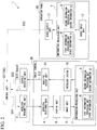
Fig. 2 is a block diagram illustrating a functional configuration that shows a vehicle operating device according to an embodiment of the present invention. -
Fig. 3 is a perspective view illustrating a state in which a tablet terminal is installed at an operation panel in the vehicle operating device according to an embodiment of the present invention. -
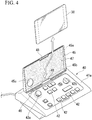
Fig. 4 is a perspective view illustrating a state in which the tablet terminal is detached from the operation panel in the vehicle operating device according to an embodiment of the present invention. -
Fig. 5 is a perspective view illustrating a stored state of the operation panel in the vehicle operating device according to an embodiment of the present invention. -
Fig. 6 is a view illustrating a processing flow in the vehicle operating device according to the embodiment of the present invention. -
Fig. 7 is an overall schematic block diagram illustrating a vehicle operating device and a vehicle according to a first modification of an embodiment of the present invention. -
Fig. 8 is an overall schematic block diagram illustrating a vehicle operating device and a vehicle according to a second modification of an embodiment of the present invention. - Hereinafter, a
vehicle operating device 1 according to an embodiment of the present invention will be described. - The
vehicle operating device 1 is provided in avehicle 100 having atraveling wheel 102 and avehicle body 101 in which thetraveling wheel 102 is provided, and operates various types of functions of thevehicle 100. In the embodiment, thevehicle 100 is a vehicle of Automated Guideway Transit (AGT) and is driven by automatic operation at normal times. - As illustrated in
Figs. 1 and2 , thevehicle operating device 1 includes awireless transmitting unit 3 configured to wirelessly transmit a state signal SI1 of thevehicle 100, awireless receiving unit 4 configured to acquire the state signal SI1 from thewireless transmitting unit 3, adisplay unit 5 configured to display a state of thevehicle 100 on the basis of the state signal SI1, aninput unit 6 configured to receive operation information of thevehicle 100 input thereto, and an information processing unit 7 configured to process the input operation information. - Also, the
vehicle operating device 1 includes aninterlock system 10 configured to change information that is able to be processed by the information processing unit 7, awireless output unit 11 configured to output an operation signal SI2 of thevehicle 100 on the basis of the processed information, and avehicle receiving unit 2 configured to receive the operation signal SI2. - Also, according to the embodiment, the
vehicle operating device 1 includes awired input unit 12 provided in thevehicle 100 and configured to receive operation information of thevehicle 100 input thereto, awired output unit 13 configured to output the operation signal SI2 of thevehicle 100 on the basis of the operation information input to the wiredinput unit 12, and avehicle receiving unit 2 configured to receive the operation signal SI2 from thewireless output unit 11. - The
wireless transmitting unit 3 is a wireless fidelity (Wi-Fi) router provided in thevehicle 100 and is connected via a wired local area network (LAN) to acontrol unit 20 configured to control a function of thevehicle 100. Thewireless transmitting unit 3 acquires the state signal SI1 of thevehicle 100 from thecontrol unit 20 and wirelessly transmits the state signal SI1. - A
wireless receiving unit 4 acquires the state signal SI1 from thewireless transmitting unit 3. This wireless receiving device is a receiving device provided in atablet terminal 30. That is, thewireless receiving unit 4 is portable. - The
display unit 5 displays states of various types of functions of thevehicle 100 on the basis of the state signal SI1 acquired by thewireless receiving unit 4. As will be described below, the various types of functions are operation information of thevehicle 100 and indicate all functions provided in the vehicle, such as interior lighting, an air conditioner, and travel of the vehicle. - Also, the
display unit 5 is a display device provided in thetablet terminal 30. That is, thedisplay unit 5 is portable. - The
input unit 6 may receive operation information of thevehicle 100 input thereto on the basis of a state of thevehicle 100 displayed on thedisplay unit 5. Theinput unit 6 is a touch sensor provided in thetablet terminal 30. That is, theinput unit 6 is portable. - Here, the following are given as examples of operation information of the
vehicle 100. -
- Operation mode of the vehicle 100 (manual operation/automatic operation)
- ON/OFF of the interior lighting
- Attenuated state of the interior lighting
- ON/OFF of headlights
- High beam/Low beam of the headlights
- ON/OFF of the air conditioner
- Set temperature of the air conditioner
- High/Low of air volume blown by the air conditioner
- Open or closed state of a door
- Travel mode of the vehicle 100 (high acceleration mode/high deceleration mode)
- Variable-voltage-variable frequency (VVVF) controller (normal mode/test mode)
- State of gradient starting (operation for starting on a hill)
- Time setting
-
- Acceleration command of the vehicle 100 (an acceleration command of the
vehicle 100 during manual operation) - Deceleration command of the vehicle 100 (a deceleration command of the
vehicle 100 during manual operation) - Neutral command of the vehicle 100 (the
vehicle 100 is in the neutral state during manual operation) - Horn
- Dead man's button
- Reset of alarm of
vehicle 100 - The
wired input unit 12 is provided in theoperation panel 40, that is connected via a wire to thevehicle 100 and has a detachable tablet terminal 30 (seeFig. 4 ), and is configured to receive operation information of thevehicle 100 input thereto. - Here, as illustrated in
Figs. 3 and4 , theoperation panel 40 includes amain body portion 41 having a rectangular shape,operation buttons 42 arranged on asurface 41a of themain body portion 41, acover portion 45 provided in themain body portion 41 and configured to open and close thesurface 41 a of themain body portion 41 having theoperation buttons 42 arranged thereon, astopper 46 provided at a rear side of the cover portion 45 (the side at which thecover portion 45 is opened and closed) of themain body portion 41, acushion pad 47 provided at aback surface 45a and an innerperipheral surface 45b of thecover portion 45 and configured to support thetablet terminal 30, and aclaw portion 48 configured to fix thetablet terminal 30 to thecover portion 45 by protruding from the innerperipheral surface 45b of thecover portion 45 along theback surface 45a. - Also, as illustrated in
Fig. 5 , a through-hole 45c is formed at thecover portion 45, and anemergency switch 42a among theoperation buttons 42 protrudes from thecover portion 45 through the through-hole 45c when thecover portion 45 is closed. Theemergency switch 42a stops travel of thevehicle 100 in case of emergency and the like. - Also, a cushion material which is the same as that of the
cushion pad 47 is provided at a surface of thestopper 46. The cushion material elastically supports an outerperipheral surface 45d at the side at which thecover portion 45 is opened and closed when thecover portion 45 is open. - The
wired input unit 12 has theoperation buttons 42 of theoperation panel 40. Thewired input unit 12 is not limited to having theoperation buttons 42, but may have an operation dial 42b and an operation handle (e.g., a MasCon (a master controller)) which is not illustrated. - The information processing unit 7 includes two information processing units: a first
information processing unit 8 configured to process the first information I among the operation information input to theinput unit 6 and a secondinformation processing unit 9 configured to process thesecond information 12. - In the embodiment, the first
information processing unit 8 and the secondinformation processing unit 9 are provided inside thetablet terminal 30. - The
interlock system 10 enables only the first information I1 to be processed by the firstinformation processing unit 8 in the operating state and enables the first information I1 and the second information I2 to be processed by the firstinformation processing unit 8 and the secondinformation processing unit 9 in the released state. - In the embodiment, the
interlock system 10 is in the released state when thetablet terminal 30 is attached to thecover portion 45 of theoperation panel 40. On the other hand, theinterlock system 10 is in the operating state when thetablet terminal 30 is detached from theoperation panel 40. - More specifically, the
interlock system 10 has, for example, a sensor (not illustrated) provided at thecover portion 45, determines whether thetablet terminal 30 is attached to thecover portion 45, and changes between the released state and the operating state. - Alternatively, the
interlock system 10 has, for example, a switch (not illustrated) provided at thecover portion 45, the switch is turned on when thetablet terminal 30 is attached to thecover portion 45 and the switch is pressed by thetablet terminal 30, and the switch is turned off when thetablet terminal 30 is detached and pressure on the switch is released. In this way, a change between the released state and the operating state occurs. - The
wired output unit 13 is provided in themain body portion 41 of theoperation panel 40. Thewired output unit 13 may output the operation signal SI2 of thevehicle 100 to thevehicle 100 on the basis of both the first information I1 and thesecond information 12 as operation information input to the wiredinput unit 12 by the operator. - That is, the first
information processing unit 8 and the secondinformation processing unit 9 are also provided at theoperation panel 40. - The
wireless output unit 11 is an output device provided in thetablet terminal 30. Thewireless output unit 11 outputs the operation signal SI2 of thevehicle 100 to thevehicle 100 on the basis of operation information input to theinput unit 6 by the operator. That is, thewireless output unit 11 is portable. - Also, when the
interlock system 10 is in the operating state, thewireless output unit 11 wirelessly outputs the operation signal SI2 of thevehicle 100 based only on the first information I1. On the other hand, when theinterlock system 10 is in the released state, thewireless output unit 11 wirelessly outputs the operation signal SI2 of the vehicle based on the processed first information I1 and second information I2. - In other words, the
wireless output unit 11 may output the operation signal SI2 based on thesecond information 12 only in the operating state. On the other hand, thewired output unit 13 may always output the operation signal SI2 based on the ranges of both the first information I1 and thesecond information 12. - The
vehicle receiving unit 2 is a Wi-Fi router provided in thevehicle 100 and configured to receive the operation signal SI2 from thewireless output unit 11. Further, thevehicle receiving unit 2 is connected via a wired LAN to thecontrol unit 20 provided in thevehicle 100. Thevehicle receiving unit 2 transmits the received operation signal SI2 to thecontrol unit 20. - In the embodiment, the
vehicle receiving unit 2 is integrated with thewireless transmitting unit 3 to form a Wi-Fi router. - Next, a data processing flow in the
vehicle operating device 1 will be described with reference toFig. 6 . - First, the operator operates the touch sensor of the
tablet terminal 30, i.e., operates theinput unit 6, and selects thevehicle 100 to which he or she desires to connect thetablet terminal 30. Then, thetablet terminal 30 is connected to thevehicle receiving unit 2 of the selectedvehicle 100 via the wireless LAN (Step 1). - Then, data communication is performed wirelessly between the
tablet terminal 30 and the vehicle 100 (Step S2). - Further, the operator operates the touch sensor of the
tablet terminal 30, i.e., operates theinput unit 6, while checking a state of thevehicle 100 by checking content displayed on the display device of thetablet terminal 30, and inputs operation information of the vehicle 100 (Step 3). - Next, whether the
interlock system 10 is in the released state (a state in which thetablet terminal 30 is detached from the operation panel 40) or in the operating state (a state in which thetablet terminal 30 is attached to the operation panel 40) is determined (Step S4). Then, it is determined as YES when theinterlock system 10 is in the released state, and it is determined as NO when theinterlock system 10 is in the operating state. - Specifically, when it is determined as NO, the first
information processing unit 8 processes operation information only when the operation information input to theinput unit 6 is information included in the first information I1. Then, the operation signal SI2 based on the first information I1 is output to thecontrol unit 20 of thevehicle 100, and thecontrol unit 20 is operated on the basis of the operation signal SI2 (Step S5). - On the other hand, when it is determined as YES, the first
information processing unit 8 and the secondinformation processing unit 9 process operation information even when the operation information input to theinput unit 6 belongs to one of the first information I1 and thesecond information 12. Then, the operation signal SI2 based on the first information I1 and the second information I2 is output to thecontrol unit 20 of thevehicle 100, and thecontrol unit 20 is operated based on the operation signal SI2 (Step S6). - According to the
vehicle operating device 1, thedisplay unit 5 and theinput unit 6 are provided in thetablet terminal 30 and are portable. Thus, the operator may carry thetablet terminal 30 and check a state of thevehicle 100 and input operation information of thevehicle 100 at any place without staying at a predetermined position of thevehicle 100. That is, a place where the operator operates a function of thevehicle 100 is not limited. - Further, for example, as shown by broken lines in
Fig. 1 , thevehicle 100 to which thetablet terminal 30 is desired to be wirelessly connected is selected among a plurality ofvehicles 100 regardless of the position of the operator, thetablet terminal 30 is connected to the selectedvehicle 100, the state signal SI1 of the selectedvehicle 100 is received, and the operation signal SI2 is output to operate thevehicle 100. - Furthermore, because the
display unit 5, theinput unit 6, and thewireless output unit 11 are provided in theportable tablet terminal 30, inputting operation information to a plurality of vehicles (or a plurality of cars in a single composition) may be performed using asingle display unit 5 and asingle input unit 6. Consequently, thedisplay unit 5 and theinput unit 6 are not required to be provided for each vehicle 100 (or car), and there is a merit in terms of cost. - Also, when the
tablet terminal 30 is separated from theoperation panel 40, theinterlock system 10 operates. Then, with operation information of thevehicle 100 limited to a range based on the first information I1, the operation signal SI2 is wirelessly transmitted to thevehicle 100 by thewireless output unit 11. That is, when the operator uses thetablet terminal 30 away from a position at which theoperation panel 40 is installed and theinterlock system 10 is in the operating state, a range in which thetablet terminal 30 can perform wireless operation is limited to a range based only on the first information I1, and wireless operation is possible only within a narrower range. - On the other hand, when the
tablet terminal 30 and theoperation panel 40 are used together, i.e., when the operator is near the position at which theoperation panel 40 is installed and theinterlock system 10 is in the released state, wireless operation is possible over a range that is wider than that based on the first information I1 and thesecond information 12. Further, wired operation by theoperation panel 40 is also possible together with the wireless operation. - Consequently, for example, when an operation range in which wireless operation does not cause a problem (e.g., operation of an air conditioner) is predefined as the first information I1 described above and an operation range in which wired operation is required to be performed (e.g., travel control of a vehicle) is predefined as the second information I2 described above, safety of an operator and the like can be ensured.
- In the embodiment, by using the
vehicle operating device 1, thevehicle 100 can be easily and safely operated while reducing cost. - Although embodiments of the present invention have been described in detail above, some design changes may be made within a scope not departing from the technical spirit of the present invention.
- For example, unlike the case of the above-described embodiment, as illustrated in
Fig. 7 , aninterlock system 10A may have aswitching operation unit 51 provided in thevehicle 100 and configured to be manually operated by an operator. Theinterlock system 10A is switched between the released state and the operating state when the switchingoperation unit 51 is operated. The switchingoperation unit 51 is an operation button or the like provided on a wall surface or the like of thevehicle 100. - Also, as illustrated in
Fig. 8 , aninterlock system 10B may have apassword input unit 61 provided in thetablet terminal 30. Theinterlock system 10B is switched between the released state and the operating state when a predetermined password is input to thepassword input unit 61 through the touch sensor. Instead of being provided in thetablet terminal 30, thepassword input unit 61 may be a monitor (a touch panel), an operation button, or the like provided on a wall surface or the like of thevehicle 100. - When the
interlock systems Figs. 7 and8 are employed, thewired operation panel 40 is unnecessary, and operations of functions of the vehicle 100 (all operations of the first information I1 and the second information 12) are wirelessly possible using only thetablet terminal 30. - Also, wireless operations of a plurality of vehicles 100 (or a plurality of cars in a single composition) may be simultaneously performed by a
single tablet terminal 30. That is, state signals of the plurality ofvehicles 100 may be acquired and displayed, and an operation signal may be output to each of the plurality ofvehicles 100 using asingle display unit 5, asingle input unit 6, and a singlewireless output unit 11. Specifically, air conditioners of allcommercial vehicles 100 may be simultaneously turned on upon starting of thevehicles 100. - Also, a
vehicle 100 operated by theoperation panel 40 may be different from avehicle 100 operated by thetablet terminal 30. - Also, the first
information processing unit 8 may be provided only in thetablet terminal 30, and the secondinformation processing unit 9 may be provided only in theoperation panel 40. In this case, a wireless facility and a wired facility for transmitting input information from theinput unit 6 provided in thetablet terminal 30 to theoperation panel 40 should be separately provided. - Also, the first
information processing unit 8 may be provided only in thetablet terminal 30, and the secondinformation processing unit 9 may be provided in both thetablet terminal 30 and theoperation panel 40. - Further, the
display unit 5, theinput unit 6, thewireless receiving unit 4, and thewireless output unit 11 may be provided in a mobile phone terminal instead of thetablet terminal 30. Also, thedisplay unit 5, theinput unit 6, thewireless receiving unit 4, and thewireless output unit 11 may be provided in separate terminals. - Further, the first information I1 and the
second information 12 described above are examples of operation information of thevehicle 100, and classification between the first information I1 and thesecond information 12 is not limited to the above-described case. For example, some of thesecond information 12 described above may be included in the first information I1. - According to the vehicle operating device and the vehicle described above, a vehicle may be easily and safely operated while reducing cost.
-
- 1
- Vehicle operating device
- 2
- Vehicle receiving unit
- 3
- Wireless transmitting unit
- 4
- Wireless receiving unit
- 5
- Display unit
- 6
- Input unit
- 7
- Information processing unit
- 8
- First information processing unit
- 9
- Second information processing unit
- 10, 10A, 10B
- Interlock system
- 11
- Wireless output unit
- 12
- Wired input unit
- 13
- Wired output unit
- 20
- Control unit
- 30
- Tablet terminal
- 40
- Operation panel
- 41
- Main body portion
- 41a
- Surface
- 42
- Operation button
- 42a
- Emergency button
- 42b
- Operation dial
- 45
- Cover portion
- 45a
- Back surface
- 45b
- Inner peripheral surface
- 45c
- Through-hole
- 45d
- Outer peripheral surface
- 46
- Stopper
- 47
- Cushion pad
- 48
- Claw portion
- 51
- Switching operation unit
- 61
- Password input unit
- 100
- Vehicle
- 101
- Vehicle body
- 102
- Traveling wheel
- I1
- First information
- 12
- Second information
- SI1
- State signal
- SI2
- Operation signal
Claims (6)
- A vehicle operating device comprising:a wireless transmitting unit provided in a vehicle and configured to wirelessly transmit a state signal of the vehicle;a portable wireless receiving unit configured to acquire the state signal from the wireless transmitting unit;a portable display unit configured to display a state of the vehicle on the basis of the state signal acquired by the wireless receiving unit;a portable input unit configured to receive operation information of the vehicle input thereto on the basis of the state of the vehicle;a first information processing unit configured to process first information among the input operation information;a second information processing unit configured to process second information, which is different from the first information, among the input operation information;an interlock system configured to enable only the first information to be processed in an operating state and enable the first information and the second information to be processed in a released state;a portable wireless output unit configured to wirelessly output an operation signal of the vehicle based only on the first information processed in the operating state; anda vehicle receiving unit provided in the vehicle and configured to receive the operation signal from the wireless output unit and transmit the operation signal to a control unit that controls a function of the vehicle on the basis of the operation signal.
- The vehicle operating device according to claim 1, wherein the interlock system includes a switching operation unit provided in the vehicle and operated to switch between the released state and the operating state.
- The vehicle operating device according to claim 1, wherein the interlock system includes a password input unit configured to switch between the released state and the operating state when a predetermined password is input.
- The vehicle operating device according to any one of claims 1 to 3, wherein:the display unit is a display device provided in a tablet terminal;the input unit is a touch sensor provided in the tablet terminal;the wireless receiving unit is a receiving device provided in the tablet terminal; andthe wireless output unit is an output device provided in the tablet terminal.
- The vehicle operating device according to claim 4, further comprising:a wired input unit provided in an operation panel, which has the tablet terminal detachably installed therein and is connected via a wire to the vehicle, and configured to receive operation information of the vehicle input thereto; anda wired output unit provided in the operation panel and configured to output an operation signal on the basis of the operation information input to the wired input unit and transmit the operation signal via a wire to the control unit, wherein:the interlock system is in the released state when the tablet terminal is installed at the operation panel and enables an operation signal of the vehicle based on the processed first information and second information to be output from at least one of the wireless output unit and the wired output unit; andthe interlock system is in the operating state when the tablet terminal is detached from the operation panel and enables an operation signal of the vehicle based only on the processed first information to be output from the wireless output unit.
- A vehicle comprising:a vehicle operating device according to any one of claims 1 to 5; anda control unit configured to operate by receiving an operation signal from the vehicle operating device.
Applications Claiming Priority (2)
| Application Number | Priority Date | Filing Date | Title |
|---|---|---|---|
| JP2014192769A JP5848422B1 (en) | 2014-09-22 | 2014-09-22 | Vehicle operating device and vehicle |
| PCT/JP2015/075451 WO2016047433A1 (en) | 2014-09-22 | 2015-09-08 | Vehicle operating device, and vehicle |
Publications (3)
| Publication Number | Publication Date |
|---|---|
| EP3182239A1 true EP3182239A1 (en) | 2017-06-21 |
| EP3182239A4 EP3182239A4 (en) | 2017-09-06 |
| EP3182239B1 EP3182239B1 (en) | 2019-01-23 |
Family
ID=55176123
Family Applications (1)
| Application Number | Title | Priority Date | Filing Date |
|---|---|---|---|
| EP15844834.0A Not-in-force EP3182239B1 (en) | 2014-09-22 | 2015-09-08 | Vehicle operating device, and vehicle |
Country Status (7)
| Country | Link |
|---|---|
| US (1) | US10942512B2 (en) |
| EP (1) | EP3182239B1 (en) |
| JP (1) | JP5848422B1 (en) |
| KR (1) | KR101938503B1 (en) |
| CN (1) | CN106716279A (en) |
| TW (1) | TWI597189B (en) |
| WO (1) | WO2016047433A1 (en) |
Families Citing this family (4)
| Publication number | Priority date | Publication date | Assignee | Title |
|---|---|---|---|---|
| JP2019044541A (en) * | 2017-09-06 | 2019-03-22 | 日立建機株式会社 | Remote control system for construction machine |
| KR102431782B1 (en) * | 2018-02-09 | 2022-08-11 | 미쓰비시덴키 가부시키가이샤 | Passenger guidance devices and passenger guidance systems in elevators |
| DE102018215511A1 (en) | 2018-09-12 | 2020-03-12 | Krones Ag | Control unit for a container handling machine |
| KR102755921B1 (en) * | 2019-12-24 | 2025-01-17 | 삼성전자 주식회사 | Electronic device including display and operation method of the same |
Family Cites Families (25)
| Publication number | Priority date | Publication date | Assignee | Title |
|---|---|---|---|---|
| US4582280A (en) * | 1983-09-14 | 1986-04-15 | Harris Corporation | Railroad communication system |
| JPS60193759A (en) | 1984-03-16 | 1985-10-02 | 株式会社東芝 | Driver's seat |
| JPH08255019A (en) * | 1995-03-17 | 1996-10-01 | Hitachi Ltd | Self-driving vehicle |
| JPH10276460A (en) | 1997-03-31 | 1998-10-13 | Omron Corp | Wireless calling method and apparatus |
| US6863247B2 (en) * | 2003-05-30 | 2005-03-08 | Beltpack Corporation | Method and apparatus for transmitting signals to a locomotive control device |
| US8280569B2 (en) * | 2004-12-09 | 2012-10-02 | General Electric Company | Methods and systems for improved throttle control and coupling control for locomotive and associated train |
| JP4822116B2 (en) * | 2006-03-29 | 2011-11-24 | 株式会社エクォス・リサーチ | Vehicle and remote control device |
| KR100991407B1 (en) | 2008-02-25 | 2010-11-02 | 한국철도기술연구원 | Automatic control system for urban railway vehicles based on ground control |
| US8290646B2 (en) * | 2008-03-27 | 2012-10-16 | Hetronic International, Inc. | Remote control system implementing haptic technology for controlling a railway vehicle |
| JP4814281B2 (en) * | 2008-05-15 | 2011-11-16 | 三菱重工業株式会社 | Vehicle for cargo handling work and control method thereof |
| US20100037072A1 (en) * | 2008-08-06 | 2010-02-11 | Sunman Engineering, Inc. | Detachable Vehicle Computing Device |
| JP5070318B2 (en) * | 2010-06-21 | 2012-11-14 | 本田技研工業株式会社 | In-vehicle remote control device |
| US10144440B2 (en) * | 2010-11-17 | 2018-12-04 | General Electric Company | Methods and systems for data communications |
| JP5704178B2 (en) * | 2011-01-31 | 2015-04-22 | トヨタ自動車株式会社 | Vehicle control device |
| CN102233887A (en) * | 2011-05-16 | 2011-11-09 | 铁道部运输局 | CTCS (China train control system)-3 train operation control system |
| KR20130011885A (en) | 2011-07-20 | 2013-01-30 | 삼성전자주식회사 | Docking station for communication terminal |
| US9173100B2 (en) * | 2011-11-16 | 2015-10-27 | Autoconnect Holdings Llc | On board vehicle network security |
| US9055022B2 (en) * | 2011-11-16 | 2015-06-09 | Flextronics Ap, Llc | On board vehicle networking module |
| US9081653B2 (en) * | 2011-11-16 | 2015-07-14 | Flextronics Ap, Llc | Duplicated processing in vehicles |
| US9008906B2 (en) * | 2011-11-16 | 2015-04-14 | Flextronics Ap, Llc | Occupant sharing of displayed content in vehicles |
| US9690729B2 (en) * | 2013-02-01 | 2017-06-27 | Audi Ag | Tablet computer dock |
| JP6061085B2 (en) * | 2013-03-07 | 2017-01-18 | 株式会社デンソー | Smart entry system |
| SE540658C2 (en) * | 2013-07-31 | 2018-10-09 | Vaederstad Holding Ab | Holder for a tablet |
| EP3073723A4 (en) * | 2013-11-19 | 2017-06-21 | Sony Corporation | Imaging system, imaging device, information processing device, method, and program |
| PL3067774T3 (en) * | 2015-03-13 | 2018-07-31 | Voegele Ag J | Operating device for a construction machine |
-
2014
- 2014-09-22 JP JP2014192769A patent/JP5848422B1/en active Active
-
2015
- 2015-09-08 US US15/511,114 patent/US10942512B2/en active Active
- 2015-09-08 WO PCT/JP2015/075451 patent/WO2016047433A1/en not_active Ceased
- 2015-09-08 EP EP15844834.0A patent/EP3182239B1/en not_active Not-in-force
- 2015-09-08 CN CN201580049144.9A patent/CN106716279A/en active Pending
- 2015-09-08 KR KR1020177006843A patent/KR101938503B1/en not_active Expired - Fee Related
- 2015-09-09 TW TW104129796A patent/TWI597189B/en active
Also Published As
| Publication number | Publication date |
|---|---|
| EP3182239A4 (en) | 2017-09-06 |
| US20170277178A1 (en) | 2017-09-28 |
| KR101938503B1 (en) | 2019-01-14 |
| US10942512B2 (en) | 2021-03-09 |
| WO2016047433A1 (en) | 2016-03-31 |
| TWI597189B (en) | 2017-09-01 |
| EP3182239B1 (en) | 2019-01-23 |
| CN106716279A (en) | 2017-05-24 |
| JP2016062570A (en) | 2016-04-25 |
| KR20170041893A (en) | 2017-04-17 |
| JP5848422B1 (en) | 2016-01-27 |
| TW201612040A (en) | 2016-04-01 |
Similar Documents
| Publication | Publication Date | Title |
|---|---|---|
| US10942512B2 (en) | Vehicle operating device, and vehicle | |
| ES3014188T3 (en) | Railway vehicle-based door control method and system | |
| ES2609401T3 (en) | Control system to operate functional units in a rail vehicle | |
| CN105966329B (en) | Method and apparatus for assisting a driver of a vehicle, especially a commercial vehicle | |
| KR101465529B1 (en) | Door control device for rail car | |
| CN107924189A (en) | remote driver assistance | |
| KR101322609B1 (en) | Integrated system of ats and atc and its operation method | |
| KR20140017157A (en) | A crewless service system for railway car | |
| CN107777491B (en) | Communication with trapped passengers in a transportation system | |
| KR100529791B1 (en) | Control apparatus of safety system for train platform | |
| US9815482B2 (en) | Train-information management device and train-crew support method | |
| KR101856850B1 (en) | Emergency Broadcasting Apparatus for Rail car | |
| US11661081B2 (en) | Control device for automated driving vehicle | |
| CN112141128B (en) | Operating device for autonomous vehicle | |
| US20220363513A1 (en) | Mobile control unit and method for remotely controlling an elevator installation | |
| JP5945145B2 (en) | Automatic folding control device | |
| CN112109640A (en) | Method for displaying the arrangement of components in a vehicle | |
| KR100867226B1 (en) | Screen door communication control system using wireless communication method | |
| KR20160064663A (en) | Evacuation guidance device and train fire evacuation guidance method using thereof | |
| KR101089819B1 (en) | System for warning information of train driver to use wireless communication data | |
| WO2015129164A1 (en) | Vehicle operations suggesting device | |
| KR101623560B1 (en) | Mobile device loss protecting system for the passenger in a taxi and method of cotnrolling the same | |
| KR20210046402A (en) | System of providing convenience service for vehicle | |
| CN115195793A (en) | Overhead travelling vehicle | |
| JP2016033001A (en) | Power supply control system for vehicle |
Legal Events
| Date | Code | Title | Description |
|---|---|---|---|
| STAA | Information on the status of an ep patent application or granted ep patent |
Free format text: STATUS: THE INTERNATIONAL PUBLICATION HAS BEEN MADE |
|
| PUAI | Public reference made under article 153(3) epc to a published international application that has entered the european phase |
Free format text: ORIGINAL CODE: 0009012 |
|
| STAA | Information on the status of an ep patent application or granted ep patent |
Free format text: STATUS: REQUEST FOR EXAMINATION WAS MADE |
|
| 17P | Request for examination filed |
Effective date: 20170314 |
|
| AK | Designated contracting states |
Kind code of ref document: A1 Designated state(s): AL AT BE BG CH CY CZ DE DK EE ES FI FR GB GR HR HU IE IS IT LI LT LU LV MC MK MT NL NO PL PT RO RS SE SI SK SM TR |
|
| AX | Request for extension of the european patent |
Extension state: BA ME |
|
| A4 | Supplementary search report drawn up and despatched |
Effective date: 20170807 |
|
| RIC1 | Information provided on ipc code assigned before grant |
Ipc: G05B 9/02 20060101ALI20170801BHEP Ipc: G05D 1/00 20060101AFI20170801BHEP |
|
| DAV | Request for validation of the european patent (deleted) | ||
| DAX | Request for extension of the european patent (deleted) | ||
| RIC1 | Information provided on ipc code assigned before grant |
Ipc: G05D 1/00 20060101ALN20180430BHEP Ipc: G05B 9/02 20060101ALN20180430BHEP Ipc: B61L 15/00 20060101ALI20180430BHEP Ipc: B61L 3/12 20060101AFI20180430BHEP Ipc: G06F 1/16 20060101ALI20180430BHEP Ipc: B61L 27/04 20060101ALI20180430BHEP Ipc: B61L 27/00 20060101ALI20180430BHEP |
|
| REG | Reference to a national code |
Ref country code: DE Ref legal event code: R079 Ref document number: 602015023816 Country of ref document: DE Free format text: PREVIOUS MAIN CLASS: G05D0001000000 Ipc: B61L0003120000 |
|
| GRAP | Despatch of communication of intention to grant a patent |
Free format text: ORIGINAL CODE: EPIDOSNIGR1 |
|
| STAA | Information on the status of an ep patent application or granted ep patent |
Free format text: STATUS: GRANT OF PATENT IS INTENDED |
|
| RIC1 | Information provided on ipc code assigned before grant |
Ipc: G06F 1/16 20060101ALI20180706BHEP Ipc: B61L 27/04 20060101ALI20180706BHEP Ipc: B61L 3/12 20060101AFI20180706BHEP Ipc: B61L 27/00 20060101ALI20180706BHEP Ipc: G05B 9/02 20060101ALN20180706BHEP Ipc: B61L 15/00 20060101ALI20180706BHEP Ipc: G05D 1/00 20060101ALN20180706BHEP |
|
| INTG | Intention to grant announced |
Effective date: 20180801 |
|
| RAP1 | Party data changed (applicant data changed or rights of an application transferred) |
Owner name: MITSUBISHI HEAVY INDUSTRIES ENGINEERING, LTD. |
|
| GRAS | Grant fee paid |
Free format text: ORIGINAL CODE: EPIDOSNIGR3 |
|
| GRAA | (expected) grant |
Free format text: ORIGINAL CODE: 0009210 |
|
| STAA | Information on the status of an ep patent application or granted ep patent |
Free format text: STATUS: THE PATENT HAS BEEN GRANTED |
|
| AK | Designated contracting states |
Kind code of ref document: B1 Designated state(s): AL AT BE BG CH CY CZ DE DK EE ES FI FR GB GR HR HU IE IS IT LI LT LU LV MC MK MT NL NO PL PT RO RS SE SI SK SM TR |
|
| REG | Reference to a national code |
Ref country code: GB Ref legal event code: FG4D |
|
| REG | Reference to a national code |
Ref country code: CH Ref legal event code: EP |
|
| REG | Reference to a national code |
Ref country code: AT Ref legal event code: REF Ref document number: 1091228 Country of ref document: AT Kind code of ref document: T Effective date: 20190215 |
|
| REG | Reference to a national code |
Ref country code: IE Ref legal event code: FG4D |
|
| REG | Reference to a national code |
Ref country code: DE Ref legal event code: R096 Ref document number: 602015023816 Country of ref document: DE |
|
| REG | Reference to a national code |
Ref country code: NL Ref legal event code: MP Effective date: 20190123 |
|
| PG25 | Lapsed in a contracting state [announced via postgrant information from national office to epo] |
Ref country code: NL Free format text: LAPSE BECAUSE OF FAILURE TO SUBMIT A TRANSLATION OF THE DESCRIPTION OR TO PAY THE FEE WITHIN THE PRESCRIBED TIME-LIMIT Effective date: 20190123 |
|
| PG25 | Lapsed in a contracting state [announced via postgrant information from national office to epo] |
Ref country code: PL Free format text: LAPSE BECAUSE OF FAILURE TO SUBMIT A TRANSLATION OF THE DESCRIPTION OR TO PAY THE FEE WITHIN THE PRESCRIBED TIME-LIMIT Effective date: 20190123 Ref country code: LT Free format text: LAPSE BECAUSE OF FAILURE TO SUBMIT A TRANSLATION OF THE DESCRIPTION OR TO PAY THE FEE WITHIN THE PRESCRIBED TIME-LIMIT Effective date: 20190123 Ref country code: SE Free format text: LAPSE BECAUSE OF FAILURE TO SUBMIT A TRANSLATION OF THE DESCRIPTION OR TO PAY THE FEE WITHIN THE PRESCRIBED TIME-LIMIT Effective date: 20190123 Ref country code: FI Free format text: LAPSE BECAUSE OF FAILURE TO SUBMIT A TRANSLATION OF THE DESCRIPTION OR TO PAY THE FEE WITHIN THE PRESCRIBED TIME-LIMIT Effective date: 20190123 Ref country code: NO Free format text: LAPSE BECAUSE OF FAILURE TO SUBMIT A TRANSLATION OF THE DESCRIPTION OR TO PAY THE FEE WITHIN THE PRESCRIBED TIME-LIMIT Effective date: 20190423 Ref country code: PT Free format text: LAPSE BECAUSE OF FAILURE TO SUBMIT A TRANSLATION OF THE DESCRIPTION OR TO PAY THE FEE WITHIN THE PRESCRIBED TIME-LIMIT Effective date: 20190523 Ref country code: ES Free format text: LAPSE BECAUSE OF FAILURE TO SUBMIT A TRANSLATION OF THE DESCRIPTION OR TO PAY THE FEE WITHIN THE PRESCRIBED TIME-LIMIT Effective date: 20190123 |
|
| PG25 | Lapsed in a contracting state [announced via postgrant information from national office to epo] |
Ref country code: LV Free format text: LAPSE BECAUSE OF FAILURE TO SUBMIT A TRANSLATION OF THE DESCRIPTION OR TO PAY THE FEE WITHIN THE PRESCRIBED TIME-LIMIT Effective date: 20190123 Ref country code: IS Free format text: LAPSE BECAUSE OF FAILURE TO SUBMIT A TRANSLATION OF THE DESCRIPTION OR TO PAY THE FEE WITHIN THE PRESCRIBED TIME-LIMIT Effective date: 20190523 Ref country code: GR Free format text: LAPSE BECAUSE OF FAILURE TO SUBMIT A TRANSLATION OF THE DESCRIPTION OR TO PAY THE FEE WITHIN THE PRESCRIBED TIME-LIMIT Effective date: 20190424 Ref country code: HR Free format text: LAPSE BECAUSE OF FAILURE TO SUBMIT A TRANSLATION OF THE DESCRIPTION OR TO PAY THE FEE WITHIN THE PRESCRIBED TIME-LIMIT Effective date: 20190123 Ref country code: RS Free format text: LAPSE BECAUSE OF FAILURE TO SUBMIT A TRANSLATION OF THE DESCRIPTION OR TO PAY THE FEE WITHIN THE PRESCRIBED TIME-LIMIT Effective date: 20190123 Ref country code: BG Free format text: LAPSE BECAUSE OF FAILURE TO SUBMIT A TRANSLATION OF THE DESCRIPTION OR TO PAY THE FEE WITHIN THE PRESCRIBED TIME-LIMIT Effective date: 20190423 |
|
| REG | Reference to a national code |
Ref country code: DE Ref legal event code: R097 Ref document number: 602015023816 Country of ref document: DE |
|
| PG25 | Lapsed in a contracting state [announced via postgrant information from national office to epo] |
Ref country code: AL Free format text: LAPSE BECAUSE OF FAILURE TO SUBMIT A TRANSLATION OF THE DESCRIPTION OR TO PAY THE FEE WITHIN THE PRESCRIBED TIME-LIMIT Effective date: 20190123 Ref country code: RO Free format text: LAPSE BECAUSE OF FAILURE TO SUBMIT A TRANSLATION OF THE DESCRIPTION OR TO PAY THE FEE WITHIN THE PRESCRIBED TIME-LIMIT Effective date: 20190123 Ref country code: CZ Free format text: LAPSE BECAUSE OF FAILURE TO SUBMIT A TRANSLATION OF THE DESCRIPTION OR TO PAY THE FEE WITHIN THE PRESCRIBED TIME-LIMIT Effective date: 20190123 Ref country code: IT Free format text: LAPSE BECAUSE OF FAILURE TO SUBMIT A TRANSLATION OF THE DESCRIPTION OR TO PAY THE FEE WITHIN THE PRESCRIBED TIME-LIMIT Effective date: 20190123 Ref country code: EE Free format text: LAPSE BECAUSE OF FAILURE TO SUBMIT A TRANSLATION OF THE DESCRIPTION OR TO PAY THE FEE WITHIN THE PRESCRIBED TIME-LIMIT Effective date: 20190123 Ref country code: DK Free format text: LAPSE BECAUSE OF FAILURE TO SUBMIT A TRANSLATION OF THE DESCRIPTION OR TO PAY THE FEE WITHIN THE PRESCRIBED TIME-LIMIT Effective date: 20190123 Ref country code: SK Free format text: LAPSE BECAUSE OF FAILURE TO SUBMIT A TRANSLATION OF THE DESCRIPTION OR TO PAY THE FEE WITHIN THE PRESCRIBED TIME-LIMIT Effective date: 20190123 |
|
| PG25 | Lapsed in a contracting state [announced via postgrant information from national office to epo] |
Ref country code: SM Free format text: LAPSE BECAUSE OF FAILURE TO SUBMIT A TRANSLATION OF THE DESCRIPTION OR TO PAY THE FEE WITHIN THE PRESCRIBED TIME-LIMIT Effective date: 20190123 |
|
| PLBE | No opposition filed within time limit |
Free format text: ORIGINAL CODE: 0009261 |
|
| STAA | Information on the status of an ep patent application or granted ep patent |
Free format text: STATUS: NO OPPOSITION FILED WITHIN TIME LIMIT |
|
| 26N | No opposition filed |
Effective date: 20191024 |
|
| PG25 | Lapsed in a contracting state [announced via postgrant information from national office to epo] |
Ref country code: SI Free format text: LAPSE BECAUSE OF FAILURE TO SUBMIT A TRANSLATION OF THE DESCRIPTION OR TO PAY THE FEE WITHIN THE PRESCRIBED TIME-LIMIT Effective date: 20190123 |
|
| PG25 | Lapsed in a contracting state [announced via postgrant information from national office to epo] |
Ref country code: TR Free format text: LAPSE BECAUSE OF FAILURE TO SUBMIT A TRANSLATION OF THE DESCRIPTION OR TO PAY THE FEE WITHIN THE PRESCRIBED TIME-LIMIT Effective date: 20190123 |
|
| REG | Reference to a national code |
Ref country code: DE Ref legal event code: R119 Ref document number: 602015023816 Country of ref document: DE |
|
| PG25 | Lapsed in a contracting state [announced via postgrant information from national office to epo] |
Ref country code: MC Free format text: LAPSE BECAUSE OF FAILURE TO SUBMIT A TRANSLATION OF THE DESCRIPTION OR TO PAY THE FEE WITHIN THE PRESCRIBED TIME-LIMIT Effective date: 20190123 |
|
| REG | Reference to a national code |
Ref country code: CH Ref legal event code: PL |
|
| PG25 | Lapsed in a contracting state [announced via postgrant information from national office to epo] |
Ref country code: DE Free format text: LAPSE BECAUSE OF NON-PAYMENT OF DUE FEES Effective date: 20200401 Ref country code: LI Free format text: LAPSE BECAUSE OF NON-PAYMENT OF DUE FEES Effective date: 20190930 Ref country code: IE Free format text: LAPSE BECAUSE OF NON-PAYMENT OF DUE FEES Effective date: 20190908 Ref country code: CH Free format text: LAPSE BECAUSE OF NON-PAYMENT OF DUE FEES Effective date: 20190930 Ref country code: LU Free format text: LAPSE BECAUSE OF NON-PAYMENT OF DUE FEES Effective date: 20190908 |
|
| REG | Reference to a national code |
Ref country code: BE Ref legal event code: MM Effective date: 20190930 |
|
| PG25 | Lapsed in a contracting state [announced via postgrant information from national office to epo] |
Ref country code: BE Free format text: LAPSE BECAUSE OF NON-PAYMENT OF DUE FEES Effective date: 20190930 |
|
| GBPC | Gb: european patent ceased through non-payment of renewal fee |
Effective date: 20190908 |
|
| PG25 | Lapsed in a contracting state [announced via postgrant information from national office to epo] |
Ref country code: GB Free format text: LAPSE BECAUSE OF NON-PAYMENT OF DUE FEES Effective date: 20190908 Ref country code: FR Free format text: LAPSE BECAUSE OF NON-PAYMENT OF DUE FEES Effective date: 20190930 |
|
| PG25 | Lapsed in a contracting state [announced via postgrant information from national office to epo] |
Ref country code: CY Free format text: LAPSE BECAUSE OF FAILURE TO SUBMIT A TRANSLATION OF THE DESCRIPTION OR TO PAY THE FEE WITHIN THE PRESCRIBED TIME-LIMIT Effective date: 20190123 |
|
| PG25 | Lapsed in a contracting state [announced via postgrant information from national office to epo] |
Ref country code: HU Free format text: LAPSE BECAUSE OF FAILURE TO SUBMIT A TRANSLATION OF THE DESCRIPTION OR TO PAY THE FEE WITHIN THE PRESCRIBED TIME-LIMIT; INVALID AB INITIO Effective date: 20150908 Ref country code: MT Free format text: LAPSE BECAUSE OF FAILURE TO SUBMIT A TRANSLATION OF THE DESCRIPTION OR TO PAY THE FEE WITHIN THE PRESCRIBED TIME-LIMIT Effective date: 20190123 |
|
| PGFP | Annual fee paid to national office [announced via postgrant information from national office to epo] |
Ref country code: AT Payment date: 20210825 Year of fee payment: 7 |
|
| REG | Reference to a national code |
Ref country code: AT Ref legal event code: UEP Ref document number: 1091228 Country of ref document: AT Kind code of ref document: T Effective date: 20190123 |
|
| PG25 | Lapsed in a contracting state [announced via postgrant information from national office to epo] |
Ref country code: MK Free format text: LAPSE BECAUSE OF FAILURE TO SUBMIT A TRANSLATION OF THE DESCRIPTION OR TO PAY THE FEE WITHIN THE PRESCRIBED TIME-LIMIT Effective date: 20190123 |
|
| REG | Reference to a national code |
Ref country code: AT Ref legal event code: MM01 Ref document number: 1091228 Country of ref document: AT Kind code of ref document: T Effective date: 20220908 |
|
| PG25 | Lapsed in a contracting state [announced via postgrant information from national office to epo] |
Ref country code: AT Free format text: LAPSE BECAUSE OF NON-PAYMENT OF DUE FEES Effective date: 20220908 |