EP3182157B1 - Procédé de création d'un modèle spatial avec un dispositif de mesure de distance tenu à la main - Google Patents
Procédé de création d'un modèle spatial avec un dispositif de mesure de distance tenu à la main Download PDFInfo
- Publication number
- EP3182157B1 EP3182157B1 EP15199917.4A EP15199917A EP3182157B1 EP 3182157 B1 EP3182157 B1 EP 3182157B1 EP 15199917 A EP15199917 A EP 15199917A EP 3182157 B1 EP3182157 B1 EP 3182157B1
- Authority
- EP
- European Patent Office
- Prior art keywords
- images
- distance
- image
- scale
- target object
- Prior art date
- Legal status (The legal status is an assumption and is not a legal conclusion. Google has not performed a legal analysis and makes no representation as to the accuracy of the status listed.)
- Active
Links
- 238000000034 method Methods 0.000 title claims description 49
- 238000005259 measurement Methods 0.000 claims description 68
- 238000013500 data storage Methods 0.000 claims description 22
- 238000004422 calculation algorithm Methods 0.000 claims description 19
- 238000000605 extraction Methods 0.000 claims description 3
- 230000004807 localization Effects 0.000 claims description 3
- 238000013507 mapping Methods 0.000 claims description 3
- 238000004590 computer program Methods 0.000 claims description 2
- 238000013459 approach Methods 0.000 description 11
- 238000004458 analytical method Methods 0.000 description 3
- 238000004364 calculation method Methods 0.000 description 3
- 238000010276 construction Methods 0.000 description 3
- 230000003287 optical effect Effects 0.000 description 3
- 230000001133 acceleration Effects 0.000 description 2
- 238000005286 illumination Methods 0.000 description 2
- 238000009434 installation Methods 0.000 description 2
- 238000004519 manufacturing process Methods 0.000 description 2
- 238000012805 post-processing Methods 0.000 description 2
- 238000012545 processing Methods 0.000 description 2
- 230000001419 dependent effect Effects 0.000 description 1
- 238000005516 engineering process Methods 0.000 description 1
- 210000004209 hair Anatomy 0.000 description 1
- 238000010191 image analysis Methods 0.000 description 1
- 238000003384 imaging method Methods 0.000 description 1
- 238000005304 joining Methods 0.000 description 1
- 239000003550 marker Substances 0.000 description 1
- 238000002360 preparation method Methods 0.000 description 1
- 230000005855 radiation Effects 0.000 description 1
- 239000004065 semiconductor Substances 0.000 description 1
- 125000006850 spacer group Chemical group 0.000 description 1
- 238000007619 statistical method Methods 0.000 description 1
- 230000000007 visual effect Effects 0.000 description 1
- 238000012800 visualization Methods 0.000 description 1
Images


Classifications
-
- G—PHYSICS
- G06—COMPUTING; CALCULATING OR COUNTING
- G06T—IMAGE DATA PROCESSING OR GENERATION, IN GENERAL
- G06T17/00—Three dimensional [3D] modelling, e.g. data description of 3D objects
-
- G—PHYSICS
- G01—MEASURING; TESTING
- G01C—MEASURING DISTANCES, LEVELS OR BEARINGS; SURVEYING; NAVIGATION; GYROSCOPIC INSTRUMENTS; PHOTOGRAMMETRY OR VIDEOGRAMMETRY
- G01C15/00—Surveying instruments or accessories not provided for in groups G01C1/00 - G01C13/00
- G01C15/002—Active optical surveying means
-
- G—PHYSICS
- G01—MEASURING; TESTING
- G01C—MEASURING DISTANCES, LEVELS OR BEARINGS; SURVEYING; NAVIGATION; GYROSCOPIC INSTRUMENTS; PHOTOGRAMMETRY OR VIDEOGRAMMETRY
- G01C11/00—Photogrammetry or videogrammetry, e.g. stereogrammetry; Photographic surveying
- G01C11/02—Picture taking arrangements specially adapted for photogrammetry or photographic surveying, e.g. controlling overlapping of pictures
-
- G—PHYSICS
- G01—MEASURING; TESTING
- G01C—MEASURING DISTANCES, LEVELS OR BEARINGS; SURVEYING; NAVIGATION; GYROSCOPIC INSTRUMENTS; PHOTOGRAMMETRY OR VIDEOGRAMMETRY
- G01C11/00—Photogrammetry or videogrammetry, e.g. stereogrammetry; Photographic surveying
- G01C11/04—Interpretation of pictures
- G01C11/06—Interpretation of pictures by comparison of two or more pictures of the same area
- G01C11/08—Interpretation of pictures by comparison of two or more pictures of the same area the pictures not being supported in the same relative position as when they were taken
-
- G—PHYSICS
- G01—MEASURING; TESTING
- G01S—RADIO DIRECTION-FINDING; RADIO NAVIGATION; DETERMINING DISTANCE OR VELOCITY BY USE OF RADIO WAVES; LOCATING OR PRESENCE-DETECTING BY USE OF THE REFLECTION OR RERADIATION OF RADIO WAVES; ANALOGOUS ARRANGEMENTS USING OTHER WAVES
- G01S17/00—Systems using the reflection or reradiation of electromagnetic waves other than radio waves, e.g. lidar systems
- G01S17/02—Systems using the reflection of electromagnetic waves other than radio waves
- G01S17/06—Systems determining position data of a target
- G01S17/08—Systems determining position data of a target for measuring distance only
-
- G—PHYSICS
- G01—MEASURING; TESTING
- G01S—RADIO DIRECTION-FINDING; RADIO NAVIGATION; DETERMINING DISTANCE OR VELOCITY BY USE OF RADIO WAVES; LOCATING OR PRESENCE-DETECTING BY USE OF THE REFLECTION OR RERADIATION OF RADIO WAVES; ANALOGOUS ARRANGEMENTS USING OTHER WAVES
- G01S17/00—Systems using the reflection or reradiation of electromagnetic waves other than radio waves, e.g. lidar systems
- G01S17/86—Combinations of lidar systems with systems other than lidar, radar or sonar, e.g. with direction finders
-
- G—PHYSICS
- G01—MEASURING; TESTING
- G01S—RADIO DIRECTION-FINDING; RADIO NAVIGATION; DETERMINING DISTANCE OR VELOCITY BY USE OF RADIO WAVES; LOCATING OR PRESENCE-DETECTING BY USE OF THE REFLECTION OR RERADIATION OF RADIO WAVES; ANALOGOUS ARRANGEMENTS USING OTHER WAVES
- G01S7/00—Details of systems according to groups G01S13/00, G01S15/00, G01S17/00
- G01S7/48—Details of systems according to groups G01S13/00, G01S15/00, G01S17/00 of systems according to group G01S17/00
- G01S7/4808—Evaluating distance, position or velocity data
-
- G—PHYSICS
- G06—COMPUTING; CALCULATING OR COUNTING
- G06T—IMAGE DATA PROCESSING OR GENERATION, IN GENERAL
- G06T3/00—Geometric image transformation in the plane of the image
- G06T3/40—Scaling the whole image or part thereof
-
- G—PHYSICS
- G06—COMPUTING; CALCULATING OR COUNTING
- G06T—IMAGE DATA PROCESSING OR GENERATION, IN GENERAL
- G06T7/00—Image analysis
- G06T7/50—Depth or shape recovery
-
- G—PHYSICS
- G06—COMPUTING; CALCULATING OR COUNTING
- G06T—IMAGE DATA PROCESSING OR GENERATION, IN GENERAL
- G06T7/00—Image analysis
- G06T7/50—Depth or shape recovery
- G06T7/521—Depth or shape recovery from laser ranging, e.g. using interferometry; from the projection of structured light
-
- G—PHYSICS
- G06—COMPUTING; CALCULATING OR COUNTING
- G06T—IMAGE DATA PROCESSING OR GENERATION, IN GENERAL
- G06T7/00—Image analysis
- G06T7/50—Depth or shape recovery
- G06T7/55—Depth or shape recovery from multiple images
- G06T7/579—Depth or shape recovery from multiple images from motion
-
- G—PHYSICS
- G06—COMPUTING; CALCULATING OR COUNTING
- G06T—IMAGE DATA PROCESSING OR GENERATION, IN GENERAL
- G06T7/00—Image analysis
- G06T7/60—Analysis of geometric attributes
- G06T7/62—Analysis of geometric attributes of area, perimeter, diameter or volume
-
- G—PHYSICS
- G06—COMPUTING; CALCULATING OR COUNTING
- G06T—IMAGE DATA PROCESSING OR GENERATION, IN GENERAL
- G06T2207/00—Indexing scheme for image analysis or image enhancement
- G06T2207/10—Image acquisition modality
- G06T2207/10016—Video; Image sequence
Definitions
- the present invention relates to a method and a handheld distance measuring device having a distance measuring unit and at least one camera for creating a spatial model of an environment. Distances between spatial points in the environment can be ascertained on the basis of the spatial model, without having to measure these distances directly.
- Methods and systems for distance measurement are used in many applications. Examples thereof are extremely precise measurements in geodetic applications, but also measurement tasks in the field of construction installation or for industrial process controllers. For these tasks, stationary, movable, or also handheld distance measuring devices are used, which execute an optical distance measurement to a selected target point. For this purpose, a laser beam is usually emitted and received again and analyzed after reflection on the target.
- Various measurement principles are available for determining the distance in this case, for example, phase measurement or time-of-flight measurement.
- portable devices to be held in the hand are used, which are applied in relation to a structure to be surveyed and then carry out a distance measurement to a surface.
- One typical handheld distance measuring device which is suitable for such applications, is described, for example, in EP 0 738 899 , EP 0 701 702 and DE102013009288 A1 .
- a method for determining a current position of a distance measuring device is disclosed in EP 1 517 117 A1 .
- a laser scanner of the distance measuring device scans a spatial segment and detects a plurality of previously attached punctiform referencing means therein, on the basis of which a current position of the distance measuring device can be ascertained.
- the necessity of preparing the measuring environment in a time-consuming manner by distributing the detectable referencing means therein for the measuring method is disadvantageous.
- EP 2 669 707 A1 discloses a further method for indirect determination of distances using a handheld distance measuring device, wherein the distances are ascertained by means of a panoramic image recorded by a camera of the distance measuring device.
- a handheld distance measuring device wherein the distances are ascertained by means of a panoramic image recorded by a camera of the distance measuring device.
- images are recorded of the environment of the spatial points, which are joined together to form a single panoramic image by means of image stitching, for example, so that a number of pixels between the two spatial points can be ascertained from the images linked to one another.
- An angle can be ascertained from this number of pixels.
- the desired distance between the two spatial points can be calculated using the law of cosines.
- a handheld distance measuring device contains for this purpose an image acquisition unit having at least one camera and an image analysis unit for joining together the images and for ascertaining the pixel number.
- this method is essentially only applicable to distances between points on the same plane, for example, on the same wall.
- a special object is to provide such a method which allows creating the spatial model with a mobile distance measuring device.
- a further object of the present invention is to provide a handheld distance measuring device for executing such a method.
- a method for creating a spatial model of a target object with a hand-held distance measuring device comprising a laser distance meter, a camera, a computing unit and a data storage device, according to the invention comprises
- the method according to the invention further comprises
- calculating the three-dimensional geometry is performed by means of a Structure-from-Motion (SfM) algorithm or a Simultaneous Localization and Mapping (SLAM) algorithm of the computing unit.
- SfM Structure-from-Motion
- SLAM Simultaneous Localization and Mapping
- the spatial model comprises image data of the images and a multitude of spatial coordinates, in particular a three-dimensional point cloud or surface model, obtained by means of feature extraction in the images and three-dimensional geometry obtained therefrom.
- the three-dimensional geometry is calculated without a scale, or with a preliminary scale.
- the step of adding the (final) scale comprises replacing the preliminary scale with the scale that is based on the at least one retrieved distance.
- calculating the scale comprises identifying a measurement point to which a distance is measured by the laser distance meter in one or more images that are not associated with the respective distance, and determining three-dimensional coordinates of the measurement point by means of forward intersection.
- a first distance of the one or more measured distances to the target object is measured simultaneously or basically simultaneously with the capturing of a first image of the plurality of images, wherein the first distance is associated with the first image, particularly wherein every distance of the one or more distances to the target object is measured simultaneously or basically simultaneously with the capturing of an image of the plurality of images.
- the method according to the invention comprises capturing with the camera a plurality of images of a planar or substantially planar surface of the target object from a plurality of different positions, and measuring with the laser distance meter one or more distances to the planar surface, wherein each of the measured distances to the planar surface is associated with a captured image of the planar surface.
- a user of the device can be guided by the device to perform the manual steps.
- the point of the three-dimensional geometry e. g. a dense or sparse point cloud
- the point of the three-dimensional geometry having the smallest orthogonal distance to the laser distance measurement emission direction is identified, particularly wherein a laser spot generated by the laser distance meter in the course of the at least one distance measurement is identified in an image.
- the laser distance measurement emission direction is intersected with a plane described by at least three points of the three-dimensional geometry, or with an object surface model, particularly obtained by meshing of a sparse or dense point cloud.
- a dense matching algorithm particularly a Semi-Global Matching (SGM) algorithm, is used to obtain the pixel location of the laser distance measurement in at least one image not associated with the laser distance measurement.
- SGM Semi-Global Matching
- a rough estimate of the scale is obtained using said intersection of the emission direction with the object surface model, and the rough estimate of the scale is refined using said dense matching algorithm.
- capturing the plurality of images comprises capturing at least three images, capturing up to 50 images, and/or recording an image stream, particularly a video stream.
- a hand-held distance measuring device for creating a spatial model of a target object comprises a laser distance meter, a camera, a computing unit and a data storage device.
- the laser distance meter is adapted to measure distances to the target object into a direction defined by an emission axis
- the camera is adapted to capture images of the target object, wherein each measured distance is associated with a captured image
- the data storage device is adapted to store the measured distances
- the computing unit is adapted to determine relative poses of the images and to calculate, based on the images and on the determined relative poses, a three-dimensional geometry of the target object.
- the computing unit is adapted, after having calculated the three-dimensional geometry, to retrieve at least one of the measured distances from the data storage device, and to add a scale to the three-dimensional geometry to obtain the spatial model of the target object, wherein the scale is based on the at least one retrieved distance.
- the camera is a wide-angle camera having a camera angle of at least 80° in particular of at least 100°.
- the hand-held distance measuring device comprises a plurality of laser distance meters for simultaneously measuring a plurality of distances to different points of the target object.
- the device comprises an inertial and/or location sensor, in particular comprising an inertial measuring unit, a gyroscope, an inclination sensor, a GNSS sensor, and/or a compass, for providing inertial and/or location data of the distance measuring device, wherein the computing unit is adapted to determine the relative poses based also on the inertial and/or location data. Alternatively, the computing unit is adapted to position the relative poses according to the location data in a post-processing step.
- the hand-held distance measuring device comprises a display device for displaying the spatial model and/or instructions to position the device in a certain pose to a user, in particular wherein the display device is embodied as a touchscreen.
- the invention also relates to a computer program product having program code which is stored on a machine-readable carrier, in particular on a data storage device of the distance measuring device according to the invention, for executing at least one the following steps of the method according to the invention:
- Figure 1 shows a handheld distance measuring device 1 for measuring distances. It has a housing, in which the required electronic components are arranged.
- the housing is implemented in this case so that the distance measuring device 1 can be held in the hand and can also be applied or fitted in a defined manner to a point to be measured.
- corresponding application edges or fitting elements which can be folded out or plugged on can be attached to the housing, as they are described, for example, in WO 02/50564 .
- the distance measuring device 1 contains, on its front side, a laser distance meter (LDM) comprising a laser emission unit 21 and a laser receiving unit 22, which have optical openings in the housing.
- LDM laser distance meter
- a display device 23 in the form of a screen and input means 24 in the form of a keypad are located on the upper side of the device 1.
- a viewfinder camera (not shown here) having a zoom functionality can be provided for recording images in the direction of the emission direction, which can be displayed on the display device 23.
- FIG. 2 shows a longitudinal section through an exemplary embodiment of a handheld distance measuring device 1 according to the invention.
- the distance measuring device 1 comprises a laser distance meter 20 for measuring distances by means of a laser beam 7 emitted in a direction defined by an emission axis 8. Furthermore, a display screen 23 and input means 24 are shown.
- the handheld distance measuring device 1 additionally has an image acquisition unit having at least one camera 40 for acquiring images of the environment.
- a computing unit 25, a data storage device 26 and an inclination and acceleration sensor 27 are shown as internal components.
- the computing unit 25 contains program code for executing a functionality for preparing a spatial model on the basis of measured distances and acquired images of the environment.
- the data storage device 26 e. g. can comprise a random access memory (RAM), a hard disk drive (HDD) and/or a flash drive.
- an energy source (not shown here) is contained in the distance measuring device 1, in particular a battery or an accumulator cell, which provides electrical energy for the electrically operated components of the distance measuring device 1.
- a digitally provided distance value - as is currently typical in the case of optically measured distances - can be stored by the data storage device 26 and further processed or transmitted by the computing unit 25 of the device and displayed on the display screen 23 to a user.
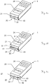
- Figures 3a to 3c show three exemplary embodiments of a handheld distance measuring device 1 according to the invention having three exemplary embodiments of the image acquisition unit.
- the cameras 40-43 in the image acquisition units shown in Figures 3a to 3c are embodied in particular such that they make it possible to create a wide-angle image by simultaneously recording an image.
- Figure 3a shows a handheld distance measuring device 1 having a single camera 40, which is arranged adjacent to the laser emission unit 21 and the laser receiving unit 22 of the laser distance meter 20. Preferably, it is adapted as a wide-angle camera having a camera angle of at least 80°.
- Figure 3b shows a handheld distance measuring device 1 having a first camera 40, which is arranged on one side of the laser emission unit 21 and the laser receiving unit 22, and a second camera 41, which is arranged on the other side.
- the two cameras 40, 41 are arranged in a line 9 that is orthogonal to the emission axis 8.
- three or more cameras can be arranged on the line 9. Images captured by these cameras are wide-angle images assembled from individual images of the two or more cameras 40, 41 arranged on the line 9.
- the angle range acquired by each of the combined images comprises at least 80°, in particular at least 120°, at least 150° or at least 180°.
- Figure 3c shows a handheld distance measuring device 1 having three cameras 40, 42, 43, which are arranged on the same side of the laser distance meter.
- Camera arrangements are implementable, in particular multiple cameras can be arranged in each case on both sides of the laser distance meter 20, or (additionally or alternatively) cameras can be arranged above and/or below the laser distance meter 20.
- Figures 4a to 4c and 5a to 5c show two further exemplary embodiments of a handheld distance measuring device 1 according to the invention, each having a further exemplary form of an image acquisition unit 45, 46 according to the invention.
- the image acquisition unit 45 shown in Figures 4a to 4c has a first camera 40, which is aligned along the emission direction of the laser distance meter 20, for recording images of the measurement region.
- the image acquisition unit 45 has a plurality of further cameras 44 - ten cameras 44 in the example shown - which are arranged in a circle around the first camera 40 and are aligned in different target directions. It is thus possible to assemble a wide-angle image from the individual images.
- the image acquisition unit 46 shown in Figures 5a to 5c is embodied in the form of a hemisphere, on the surface of which a plurality of cameras 44 are arranged, for example, 18 cameras. It is also possible using this embodiment to assemble a wide-angle image from a plurality of simultaneously recorded individual images, wherein the recording angle can be up to 180° or even larger.
- Embodiments having two hemispheres are also possible, which are attached laterally to the distance measuring device 1, for example, one hemisphere above and one below the device.
- WLCs have an image sensor, for example, a CMOS image sensor, lenses, and spacers, which are produced in the wafer level, stacked, and joined together to form a single part.
- the camera is then housed as an integrated overall system on the surface of a semiconductor plate.
- WLCs are particularly mechanically stable and are only to be calibrated once during the manufacturing.
- cameras having so-called backside illumination can also be used, for example, based on the OmniBSI-2TM from OmniVision®.
- Cameras 40-44 of all above-described embodiments can also advantageously be embodied for recording high-contrast images (or high dynamic range images (HDRI)).
- the cameras have digital image sensors having high dynamic range and are equipped, for example, with the chip OV10626 from OmniVision® or comparable products.
- This technology which is heretofore known, for example, from camera systems for use as assistance systems in motor vehicles, enables the simultaneous acquisition of multiple illumination stages and is therefore suitable for simultaneously imaging both sunlit regions and also regions lying in shadow with high contrast, i.e., avoiding overexposure and underexposure.
- the feature identification and feature extraction can advantageously thus be optimized in the entire image region, even in the event of difficult light conditions.
- the cameras 40-44 can also be embodied for rapidly recording exposure series, or the image acquisition unit has at least one camera for recording images of bright regions and at least one camera for recording images of dark regions.
- Figures 6a and 6b illustrate the simultaneous measuring of distances 50, 51, 52 to a target object (house 3) and capturing images 60, 61, 62 of the target object 3.
- Figure 6a shows a first measurement
- Figure 6b shows consecutive measurements.
- the depicted hand-held distance-measurement device 1 has a laser distance meter (LDM) and a wide-angle camera that can be used to perform photogrammetric measurements.
- An image 60, 61, 62 from the wide-angle camera is associated with each distance-measurement 50, 51, 52.
- multiple laser distance meters can be used to enhance the solution, making it more robust and accurate.
- the association of the image and the distance-measurement can be achieved by simultaneously taking the image and measuring the distance.
- the device may comprise a clock or another device defining a common time frame to which each observation can be related.
- Computer vision algorithms are used to determine the relative poses 70, 71, 72 of the device 1 during each of the measurements 50, 51, 52.
- the LDM measurements 50, 51, 52 are used to provide scaling to a scale-free computer vision solution.
- a three-dimensional (3D) position relative to the poses 70, 71, 72 can be found for each selected point in an image, which can be identified in at least a second image - either by manual or automatic matching.
- the user can use the device 1 to measure distances on an object of interest or measure inclinations with the aid of a built-in inertial measurement unit (IMU).
- IMU is an electronic device that measures physical forces acting upon it. It is typically sensitive to linear accelerations through accelerometers and angular velocities through gyroscopes.
- a compass is also included. Easy field measurements that can be used as control measurements are performed on the device directly after the recording, more complicated analysis can be performed using suitable office software.
- a user takes a plurality of images, e. g. between two and 20 images, in this example three images 60, 61, 62, of a single target object 3.
- the user may record an image stream (e. g. video stream) instead of separate images.
- the processing starts on the device 1.
- the user can be actively guided by the device 1 to add additional positions in order to improve accuracy.
- final processing starts on the device 1, so that a short time later the - unscaled - 3D geometry (not to be confused with the scaled 3D model) of the scene and the target object 3 therein is available on the device 1.
- the user can now use the calculated 3D geometry to photogrammetrically measure individual points from the images.
- the user can also perform simple combined measurements such as linear distances or slope determinations using an additional accelerometer. Accuracy can be indicated for every measurement that the user makes.
- the user measurements are denoted in physical units after the three-dimensional geometry has been scaled using one or more laser distance measurements.
- the generated model can be oriented with respect to horizon.
- a "G-vector” i.e. information from an accelerometer or inclinometer of the device
- the generated model can be oriented with respect to horizon.
- positional information e. g. from an internal receiver of the device or via a connected Smartphone or tablet PC
- the model and/or its heading angle optionally can be geo-referenced (geo-tag).
- the user can add additional captures of the same scene at any point later to further enhance the model.
- a desktop PC In the office, on a desktop PC, the user can perform further or more complicated measurements in the images.
- an object model is calculated on the desktop PC which the user can use for 3D visualization or performing additional measurements.
- Either a dense point cloud (the output of a dense matching algorithm) or a textured, meshed or simplified model can be made available.
- LDM to camera calibrations are generally known from the art.
- a calibration can comprise a camera calibration first.
- close-range images are taken of a flat wall with the laser spot visible thereon in the image.
- a LDM measurement is recorded.
- the laser spot positions are found in the images and a non-linear system of equations is solved to obtain the LDM calibration.
- photogrammetric markers at known positions on the wall recorded in the image can be used to photogrammetrically verify the calibration.
- the LDM laser and the camera are calibrated, it is easy to identify the location of the laser spot 10, 11, 12 in an image 60, 61, 62 that was recorded at the same time - even if the laser spot 10, 11, 12 itself is not visible (e. g. due to bright outdoor conditions).
- the location of the laser spot 10, 11, 12 in the current image 60, 61, 62 can be indicated to the user using some sort of image marker, e. g. cross hairs.
- the challenge lies in identifying the object point where a first laser spot 10 hit in one or more of the other images 61, 62 or equivalently in the 3D model. Typically, this is not an easy task if the laser spot 10 did not hit a significant image feature, i.e. a feature that can be easily found in one of the other images by itself. Three exemplary approaches to perform this task according to the invention are described further below.
- the chosen approach leads to the laser spot 10 being identified in one or more of the other images 61, 62 instead of in the 3D model, forward intersection is used to find the 3D coordinates of the laser spot. Then the 3D reconstruction generated by Structure-from-Motion is scaled such that the distance from the LDM module to the 3D coordinates of the laser spot 10 corresponds to the distance 50 measured by the LDM. To increase the robustness and accuracy it makes sense to repeat the above procedure for different LDM measurements and potentially other images. If this is computationally feasible (also depends on the above variant chosen), the procedure is repeated for different parameters and the results are combined to a single scaling factor.
- the first approach comprises "local semi-global matching" (SGM).
- SGM local semi-global matching
- the user is asked to keep a planar or basically planar (flat) surface area in the center of the first image. While recording the first image a distance to this planar surface is measured using the LDM.
- To find the laser spot 10 of the first image 60 in the second image 61 first the relevant part of the second image 61 is selected.
- the laser spot 10 of the first image 60 must be on the same epipolar line in the second image 61.
- some bounds can be put on the distance between the two camera positions 70, 71 (e. g. between one metre and 25 metres) to limit the search space along the epipolar line, as we already know the distance to the laser spot in the first image from the LDM.
- the relevant parts of the images 60, 61 are selected and rectified.
- the relevant part of the epipolar line and several (e. g. up to 1000) image rows below and above it are selected to aid in the matching. Rectification means the epipolar lines are now horizontal and the laser spot 10 from the first image 60 must lie in the same row of the second image 61.
- SGM or a similar algorithm is used to find the exact location of the first image's laser spot 10 in the second image 61. It is important that a (semi-)global matching algorithm is used, so surrounding significant features are used to find a matched position for the laser spot 10 of the first image 60 in the second image 61.
- the reconstruction is then scaled such that the laser spot distance from the first image 60 matches the distance 50 of the LDM measurement.
- the user can be asked to take a second image 61 and distance measurement 51 after moving forward towards the object 3. Because the image contents between the two images 60, 61 are thus more similar than for normal sideways movement with respect to the object 3, the dense matching between the two images 60, 61 usually works better. This allows improving the robustness of the scale estimation.
- the location of the laser spot 10, 11, 12 in other images 60, 61, 62 and thereby the robustness and accuracy of the scale estimation can optionally be improved by adding more images of the target area where the spot 10, 11, 12 is located. At the price of increased user effort and computational time this makes the dense reconstruction of the target object 3 more robust and more accurate.
- the additional images can be recorded simultaneously by an additional Viewfinder camera having an increased magnification compared to the photogrammetric camera.
- the second approach comprises a "Structure-from-Motion triangulation".
- the user is asked to keep an - at least approximately - planar surface area in the centre of each image 60, 61, 62.
- a distance 50, 51, 52 is measured by means of the LDM.
- SfM Structure-from-Motion
- a ray from each reconstructed LDM position 70, 71, 72 is intersected with the SfM point cloud. This is done by intersecting the LDM ray with a plane described by at least three SfM points close to the LDM ray.
- the laser spot 10, 11, 12 on the object 3 lies in this plane.
- the SfM reconstruction can be scaled such that the distance to the object matches the LDM measured distance 50, 51, 52.
- the laser spot 10, 11, 12 can be first found in the other image(s) from the geometric relationships between the 2D features (e. g. using a homography). Then the 3D coordinates of the laser spot are computed using forward intersection of the obtained corresponding 2D image coordinates in at least two images in total.
- the procedure can be repeated for different choices of surrounding SfM points. This creates multiple scaling factors for each LDM measurement.
- a statistical method can be used to retrieve a single scaling factor in a robust way.
- a (semi-)dense 3D reconstruction algorithm is used on the device 1 to compute the scale-free geometry.
- the 3D coordinates of each LDM target position can be chosen as the reconstructed point closest to the intersection of the LDM with the geometry.
- the 3D coordinates of the laser spot 10, 11, 12 on the object 3 can be refined using the meshing approach described above, where instead of SfM sparse points already (semi-)dense points are used.
- a third approach combines the first and second approaches. First, a rough scale estimate is obtained using the SfM triangulation method. Then the result is used to run a reduced version of the local SGM method to refine the scale estimate.
- the SGM problem can be reduced in terms of the image areas considered and/or in terms of the depth range considered. Both provide a significant speedup of the SGM calculation.
- the scale estimate retrieved from two or more images can optionally be verified in other images by analysis of the image patches at the predicted locations.
- Figure 7 shows a flow chart for illustrating an exemplary embodiment of a method 100 according to the invention.
- the method 100 starts with the user pointing the device toward the target object and triggering the first measurement 110, which is then performed by the device which simultaneously measures a first distance 50 to the target object and captures a first image 60 of the target object. While the first distance 50 is saved in a data storage for later retrieval (step 130), the method 100 continues with the user triggering a second measurement (and subsequently further measurements) 120. Further distance(s) 51, 52 are measured and saved in the data storage, and further image(s) 61, 62 are captured simultaneously with each distance measurement. Alternatively, only a first distance 50 is measured, and the further image(s) 61, 62 are captured without a simultaneous distance measurement.
- a computing unit of the device determines relative poses of the images 60-62 (step 140). After the end of the capturing, the computing unit calculates based on the images 60-62 and on the relative poses an unscaled 3D geometry of the target object (step 150).
- one or more of the saved distances 50-52 are retrieved from the data storage.
- the positions of the points on the target object to which the distances have been measured are identified in other images in order to calculate a scale 160.
- This scale is then added to the formerly unscaled 3D geometry (step 170) so that a scaled spatial model of the target object results 180.
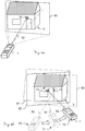
- Figure 8 shows a spatial model 30 of the target object of Figures 6a and 6b , displayed on a touchscreen 28 of an exemplary embodiment of a hand-held distance measuring device 1 according to the invention.
- Said device 1 has a hemispherical image acquisition unit 46 as described in Figures 5a-c , and also means for transmitting spatial model data to an external device such as a personal computer 2 by means of a wireless connection 29, e. g. a Bluetooth or Wi-Fi connection.
- a wireless connection 29 e. g. a Bluetooth or Wi-Fi connection.
- the spatial model 30 comprises a scaled geometry, e. g. a 3D point cloud or mesh, and texture from the images. Alternatively, only the geometry without special texture can be displayed. Zooming in and out is possible in both cases, as is rotating the view.
- the spatial model 30 It is possible to perform further measurements in the spatial model 30, for example distance or area calculations. For instance, by marking two points in the spatial model 30 on the touchscreen 28 of the distance measuring device 1 or using a mouse of the computer 2, a user can have the distance between the two points calculated and displayed.
- data from inertial sensors or a compass may be used to determine slopes or orientations of surfaces in the 3D model.
Claims (15)
- Procédé (100) de création d'un modèle spatial (30) d'un objet cible (3) avec un dispositif de mesure de distance portatif (1), le dispositif comprenant un télémètre laser (20), une caméra (40), une unité de calcul (25) et un dispositif de stockage de données (26), le procédé comprenant les étapes consistant à- mesurer avec le télémètre laser (20) une ou plusieurs distances (50, 51, 52) à une surface plane de l'objet cible (3),- stocker (130) lesdites une ou plusieurs distances mesurées (50, 51, 52) dans le dispositif de stockage de données (26),- capturer avec la caméra (40) une pluralité d'images (60, 61, 62) de la surface de l'objet cible (3) à partir de différentes positions, chacune des distances mesurées (50, 51, 52) étant associée à l'une des images capturées (60, 61, 62),- déterminer (140) avec l'unité de calcul (25) des poses relatives de caméra (70, 71, 72) pour la pluralité d'images (60, 61, 62) et- calculer (150) avec l'unité de calcul (25), sur la base de la pluralité d'images (60, 61, 62) et des poses relatives de caméra (70, 71, 72) déterminées, une géométrie tridimensionnelle de l'objet cible (3),caractérisé en ce
qu'après que la géométrie tridimensionnelle (150) a été calculée, le procédé (100) comprend en outre les étapes consistant à- extraire au moins une des distances mesurées (50, 51, 52) du dispositif de stockage de données (26), et- ajouter (170) l'échelle à la géométrie tridimensionnelle pour obtenir (180) le modèle spatial (30) de l'objet cible (3), l'échelle étant calculée (160) sur la base de ladite au moins une distance extraite,dans lequel le calcul (160) de l'échelle comprend les étapes consistant à- identifier un point de mesure (10, 11, 12) auquel une distance (50, 51, 52) est mesurée par le télémètre laser (20) dans une ou plusieurs images (60, 61, 62) qui ne sont pas associés à la distance respective (50, 51, 52) et- déterminer des coordonnées tridimensionnelles du point de mesure (10, 11, 12) au moyen d'une intersection avant,dans lequel, pour calculer (160) l'échelle,- un point de la géométrie tridimensionnelle qui présente la plus petite distance orthogonale à la direction d'émission de mesure de distance au laser (8) est identifié, en particulier un spot laser (10, 11, 12) généré par le télémètre laser (20) au cours de ladite au moins une mesure de distance étant identifié dans une image (60, 61, 62) ; et/ou- la direction d'émission de mesure de distance au laser (8) est coupée par un plan décrit par au moins trois points de la géométrie tridimensionnelle, ou par un modèle de surface de l'objet, obtenu en particulier par maillage d'un nuage de points clairsemé ou dense ; et/ou- un algorithme de mise en correspondance dense, en particulier un algorithme d'alignement semi-global, est utilisé pour obtenir une localisation de pixels d'une mesure de distance au laser dans au moins une image (60, 61, 62) non associée à la même mesure de distance au laser. - Procédé (100) selon la revendication 1,
caractérisé en ce que
le calcul de la géométrie tridimensionnelle est effectué au moyen d'un algorithme de structure acquise à partir d'un mouvement ou d'un algorithme de localisation et cartographie simultanées de l'unité de calcul. - Procédé (100) selon la revendication 1 ou la revendication 2,
caractérisé en ce que
le modèle spatial (30) comprend des données d'image des images (60, 61, 62) et une multitude de coordonnées spatiales, en particulier un nuage de points ou un modèle de surface tridimensionnel, obtenu au moyen d'une extraction de caractéristiques dans les images (60, 61, 62) et en utilisant la géométrie tridimensionnelle. - Procédé (100) selon l'une quelconque des revendications 1 à 3,
caractérisé en ce que
la géométrie tridimensionnelle est calculée sans échelle. - Procédé (100) selon l'une quelconque des revendications 1 à 3,
caractérisé en ce que
la géométrie tridimensionnelle est calculée avec une échelle préliminaire, et l'étape consistant à ajouter (170) l'échelle consiste à remplacer l'échelle préliminaire par l'échelle qui est basée sur ladite au moins une distance extraite. - Procédé (100) selon l'une quelconque des revendications 1 à 5,
caractérisé en ce
qu'une première distance (50) de la pluralité de distances à l'objet cible (3) est mesurée simultanément ou essentiellement simultanément avec la capture d'une première image (60) de la pluralité d'images, la première distance (50) étant associée à la première image (60), en particulier chaque distance (50, 51, 52) de la pluralité de distances à l'objet cible (3) étant mesurée simultanément ou essentiellement simultanément avec la capture d'une image (60, 61, 62) de la pluralité d'images. - Procédé (100) selon l'une quelconque des revendications 1 à 6,
caractérisé en ce
qu'un utilisateur du dispositif (1) est guidé par le dispositif (1) pour effectuer les étapes consistant à mesurer des distances à la surface et à capturer des images de la surface. - Procédé (100) selon l'une quelconque des revendications 1 à 7,
caractérisé en ce
qu'une estimation grossière de l'échelle est obtenue en identifiant le point le plus proche ou en utilisant l'intersection de la direction d'émission (8) avec le modèle de surface de l'objet, et l'estimation grossière de l'échelle est affinée en utilisant l'algorithme de mise en correspondance dense. - Procédé (100) selon l'une quelconque des revendications 1 à 8,
caractérisé en ce que
l'étape consistant à capturer la pluralité d'images (60, 61, 62) consiste à enregistrer un flux d'images, en particulier un flux vidéo. - Dispositif de mesure de distance portatif (1) pour la création d'un modèle spatial (30) d'un objet cible (3), le dispositif (1) comprenant un télémètre laser (20), une caméra (40), une unité de calcul (25), un dispositif d'affichage (23) et un dispositif de stockage de données (26), dans lequel- le dispositif d'affichage (23) est adapté à afficher le modèle spatial (30),- le télémètre laser (20) est adapté à mesurer des distances (50, 51, 52) à une surface plane ou sensiblement plane de l'objet cible (3) dans une direction définie par un axe d'émission (8),- la caméra (40) est adaptée à capturer des images (60, 61, 62) de la surface de l'objet cible (3), chaque distance mesurée (50, 51, 52) étant associée à une image capturée (60, 61, 62),- le dispositif de stockage de données (26) est adapté à stocker les distances mesurées (50, 51, 52) et- l'unité de calcul (25) est adaptée à déterminer des poses relatives (70, 71, 72) des images (60, 61, 62) et à calculer, sur la base des images (60, 61, 62) et des poses relatives (70, 71, 72) déterminées, une géométrie tridimensionnelle de l'objet cible (3),caractérisé en ce que
l'unité de calcul (25) est adaptée, après avoir calculé la géométrie tridimensionnelle,- à extraire au moins l'une des distances mesurées (50, 51, 52) du dispositif de stockage de données (26) et- à ajouter l'échelle à la géométrie tridimensionnelle pour obtenir le modèle spatial (30) de l'objet cible (3), l'échelle étant calculée sur la base de ladite au moins une distance extraite,dans lequel le calcul (160) de l'échelle comprend les étapes consistant à- identifier un point de mesure (10, 11, 12) auquel une distance (50, 51, 52) est mesurée par le télémètre laser (20) dans une ou plusieurs images (60, 61, 62) qui ne sont pas associées à la distance respective (50, 51, 52) ; et- déterminer des coordonnées tridimensionnelles du point de mesure (10, 11, 12) au moyen d'une intersection avant,dans lequel, pour calculer (160) l'échelle,- un point de la géométrie tridimensionnelle qui présente la plus petite distance orthogonale à la direction d'émission de mesure de distance au laser (8) est identifié, en particulier un spot laser (10, 11, 12) généré par le télémètre laser (20) au cours de ladite au moins une mesure de distance étant identifié dans une image (60, 61, 62) ; et/ou- la direction d'émission de mesure de distance au laser (8) est coupée par un plan décrit par au moins trois points de la géométrie tridimensionnelle, ou par un modèle de surface de l'objet, obtenu en particulier par maillage d'un nuage de points clairsemé ou dense ; et/ou- un algorithme de mise en correspondance dense, en particulier un algorithme d'alignement semi-global, est utilisé pour obtenir une localisation de pixels d'une mesure de distance au laser dans au moins une image (60, 61, 62) non associée à la même mesure de distance au laser. - Dispositif de mesure de distance portatif (1) selon la revendication 10,
caractérisé en ce que
la caméra (40) est une caméra grand angle ayant un angle de caméra d'au moins 80°, en particulier d'au moins 100°. - Dispositif de mesure de distance portatif (1) selon la revendication 10 ou la revendication 11,
caractérisé par
une pluralité de caméras (40-44), en particulier au moins trois caméras, dans lequel les images (50, 51, 52) sont des images grand angle assemblées à partir d'images individuelles de la pluralité de caméras (40-44), dans lequel la plage angulaire acquise par chacune des images (50, 51, 52) comprend au moins 80°, en particulier au moins 120°, au moins 150° ou au moins 180°, en particulier dans lequel les caméras (40-44) sont disposées sur une ligne (9) qui est orthogonale à l'axe d'émission (8) ou sont disposées sous la forme d'un hémisphère (46). - Dispositif de mesure de distance portatif (1) selon l'une des revendications 10 à 12,
caractérisé par- une pluralité de télémètres laser (20) pour mesurer simultanément une pluralité de distances à différents points de l'objet cible (3), et/ou- un capteur inertiel et/ou de localisation (26), comprenant en particulier une unité de mesure inertielle, un gyroscope, un capteur d'inclinaison, un capteur GNSS et/ou une boussole, pour fournir des données inertielles et/ou de localisation du dispositif de mesure de distance (1), dans lequel l'unité de calcul (27) est adaptée à déterminer les poses relatives (70, 71, 72) également sur la base des données inertielles et/ou de localisation. - Dispositif de mesure de distance portatif (1) selon l'une quelconque des revendications 10 à 13,
caractérisé en ce que
le dispositif d'affichage (23) est adapté à afficher des instructions pour positionner le dispositif (1) dans une certaine pose (70, 71, 72) à un utilisateur, en particulier dans lequel le dispositif d'affichage est réalisé sous la forme d'un écran tactile (28). - Produit programme d'ordinateur avec un code de programme qui est stocké sur un support lisible par machine, en particulier sur un dispositif de stockage de données (26) du dispositif de mesure de distance (1) selon l'une des revendications 10 à 14, pour exécuter les étapes du procédé (100) selon l'une des revendications 1 à 9.
Priority Applications (3)
| Application Number | Priority Date | Filing Date | Title |
|---|---|---|---|
| EP15199917.4A EP3182157B1 (fr) | 2015-12-14 | 2015-12-14 | Procédé de création d'un modèle spatial avec un dispositif de mesure de distance tenu à la main |
| CN201611144009.5A CN106871878B (zh) | 2015-12-14 | 2016-12-13 | 手持测距装置及利用其创建空间模型的方法、存储介质 |
| US15/378,956 US10140756B2 (en) | 2015-12-14 | 2016-12-14 | Method for creating a spatial model with a hand-held distance measuring device |
Applications Claiming Priority (1)
| Application Number | Priority Date | Filing Date | Title |
|---|---|---|---|
| EP15199917.4A EP3182157B1 (fr) | 2015-12-14 | 2015-12-14 | Procédé de création d'un modèle spatial avec un dispositif de mesure de distance tenu à la main |
Publications (2)
| Publication Number | Publication Date |
|---|---|
| EP3182157A1 EP3182157A1 (fr) | 2017-06-21 |
| EP3182157B1 true EP3182157B1 (fr) | 2020-04-15 |
Family
ID=54979403
Family Applications (1)
| Application Number | Title | Priority Date | Filing Date |
|---|---|---|---|
| EP15199917.4A Active EP3182157B1 (fr) | 2015-12-14 | 2015-12-14 | Procédé de création d'un modèle spatial avec un dispositif de mesure de distance tenu à la main |
Country Status (3)
| Country | Link |
|---|---|
| US (1) | US10140756B2 (fr) |
| EP (1) | EP3182157B1 (fr) |
| CN (1) | CN106871878B (fr) |
Families Citing this family (25)
| Publication number | Priority date | Publication date | Assignee | Title |
|---|---|---|---|---|
| US9501700B2 (en) | 2012-02-15 | 2016-11-22 | Xactware Solutions, Inc. | System and method for construction estimation using aerial images |
| SE543568C2 (en) * | 2017-02-27 | 2021-03-30 | Katam Tech Ab | Improved forest surveying apparatus and method using video sequences to generate 3D models and for height determination |
| SE541287C2 (en) | 2017-02-27 | 2019-06-11 | Katam Tech Ab | Forest surveying apparatus and method using video sequences to generate 3D models |
| CN109389677B (zh) * | 2017-08-02 | 2022-10-18 | 珊口(上海)智能科技有限公司 | 房屋三维实景地图的实时构建方法、系统、装置及存储介质 |
| WO2019045711A1 (fr) * | 2017-08-31 | 2019-03-07 | Sony Mobile Communications Inc. | Dispositifs de localisation et de cartographie simultanées (slam) à détermination d'échelle et leurs procédés de fonctionnement |
| DE102017215766A1 (de) * | 2017-09-07 | 2019-03-07 | Robert Bosch Gmbh | Verfahren zum Betrieb eines Laserentfernungsmessgeräts |
| CN107747910A (zh) * | 2017-09-19 | 2018-03-02 | 浙江大学 | 一种视觉引导的隧道标志点坐标激光测量系统及方法 |
| JP6559201B2 (ja) * | 2017-09-29 | 2019-08-14 | 株式会社トプコン | 解析システム、解析方法、及び解析プログラム |
| US11393114B1 (en) * | 2017-11-08 | 2022-07-19 | AI Incorporated | Method and system for collaborative construction of a map |
| US11145116B2 (en) | 2017-11-21 | 2021-10-12 | Faro Technologies, Inc. | System and method of scanning an environment and generating two dimensional images of the environment |
| US10445913B2 (en) | 2018-03-05 | 2019-10-15 | Faro Technologies, Inc. | System and method of scanning and editing two dimensional floorplans |
| CN108507542B (zh) * | 2018-04-02 | 2021-03-09 | 北京理工大学 | 一种超高速运动目标姿态测量系统及方法 |
| CN109084700B (zh) * | 2018-06-29 | 2020-06-05 | 上海摩软通讯技术有限公司 | 物品的三维位置信息获取方法及系统 |
| CN108981719B (zh) * | 2018-10-12 | 2024-03-01 | 中国空气动力研究与发展中心超高速空气动力研究所 | 一种超高速飞行模型位姿变化测量装置及方法 |
| CN109883400B (zh) * | 2018-12-27 | 2021-12-10 | 南京国图信息产业有限公司 | 基于yolo-sitcol的固定站自动目标检测与空间定位方法 |
| CN110132272A (zh) * | 2019-06-20 | 2019-08-16 | 河北工业大学 | 一种用于空间碎片运动参数的测量方法及系统 |
| BR112021026125A2 (pt) * | 2019-07-16 | 2022-05-10 | Bodidata Inc | Sistemas e métodos para melhorar a cobertura e a eficiência do escaneamento de radar |
| FR3102266B1 (fr) * | 2019-10-16 | 2022-03-25 | Maxime Roland Marcel Burger | Système et procédé de génération d’une liste d’articles d’équipement d’immeubles, et programme d’ordinateur |
| US11094113B2 (en) | 2019-12-04 | 2021-08-17 | Geomni, Inc. | Systems and methods for modeling structures using point clouds derived from stereoscopic image pairs |
| US11398070B1 (en) * | 2020-01-22 | 2022-07-26 | Amazon Technologies, Inc. | Boundary approximation utilizing radar |
| US11836940B2 (en) * | 2020-06-15 | 2023-12-05 | Zebra Technologies Corporation | Three-dimensional sensor acuity recovery assistance |
| US11297247B1 (en) | 2021-05-03 | 2022-04-05 | X Development Llc | Automated camera positioning for feeding behavior monitoring |
| WO2023085997A1 (fr) * | 2021-11-09 | 2023-05-19 | Saab Ab | Procédé, produit logiciel et système pour une navigation dépourvue de gnss |
| CN114279324B (zh) * | 2021-12-10 | 2024-03-29 | 苏交科集团股份有限公司 | 一种预制构件外观质量全方位智能检测方法 |
| WO2024025851A1 (fr) * | 2022-07-26 | 2024-02-01 | Becton, Dickinson And Company | Système et procédé d'estimation d'une distance et/ou d'un angle d'un objet par rapport à un dispositif de capture d'image |
Citations (1)
| Publication number | Priority date | Publication date | Assignee | Title |
|---|---|---|---|---|
| DE102013009288A1 (de) * | 2013-06-04 | 2014-12-04 | Testo Ag | 3D-Aufnahmevorrichtung, Verfahren zur Erstellung eines 3D-Bildes und Verfahren zur Einrichtung einer 3D-Aufnahmevorrichtung |
Family Cites Families (16)
| Publication number | Priority date | Publication date | Assignee | Title |
|---|---|---|---|---|
| DE4316348A1 (de) | 1993-05-15 | 1994-11-17 | Wild Heerbrugg Ag | Vorrichtung zur Distanzmessung |
| US6879921B2 (en) | 2000-12-21 | 2005-04-12 | Leica Geosystems, A.G. | Device for measuring distances, distance measurer and stop element therefor |
| FR2836215B1 (fr) * | 2002-02-21 | 2004-11-05 | Yodea | Systeme et procede de modelisation et de restitution tridimensionnelle d'un objet |
| EP1517117A1 (fr) | 2003-09-22 | 2005-03-23 | Leica Geosystems AG | Méthode et système pour la détermination de la position actuelle d'un appareil de postionement |
| US8228367B2 (en) * | 2009-04-09 | 2012-07-24 | Telefonaktiebolaget Lm Ericsson (Publ) | Three-dimensional reconstruction of scenes and objects |
| EP2669707B1 (fr) | 2012-05-29 | 2019-07-24 | Leica Geosystems AG | Procédé et appareil de mesure de distance pouvant être tenu à la main destinés à la mesure d'éloignement indirecte au moyen d'une fonction de détermination d'angle assistée par image |
| ES2693785T3 (es) * | 2013-01-21 | 2018-12-13 | Vricon Systems Aktiebolag | Procedimiento y disposición para desarrollar un modelo tridimensional de un entorno |
| US9662564B1 (en) * | 2013-03-11 | 2017-05-30 | Google Inc. | Systems and methods for generating three-dimensional image models using game-based image acquisition |
| US10412368B2 (en) * | 2013-03-15 | 2019-09-10 | Uber Technologies, Inc. | Methods, systems, and apparatus for multi-sensory stereo vision for robotics |
| EP2829842B1 (fr) | 2013-07-22 | 2022-12-21 | Hexagon Technology Center GmbH | Procédé, système et produit programme d'ordinateur pour déterminer un volume absolu d'un stock à l'aide d'un algorithme d'acquisition de structure à partir d'un mouvement |
| EP3063553B1 (fr) * | 2013-11-01 | 2019-12-11 | Robert Bosch GmbH | Système et procédé de mesure par balayages laser |
| US20150248772A1 (en) * | 2014-02-28 | 2015-09-03 | Semiconductor Components Industries, Llc | Imaging systems and methods for monitoring user surroundings |
| EP2918972B1 (fr) | 2014-03-14 | 2019-10-09 | Leica Geosystems AG | Procédé et appareil de mesure d'éloignement portatif pour la génération d'un modèle spatial |
| CN104268379B (zh) * | 2014-09-12 | 2017-02-01 | 北京诺亚星云科技有限责任公司 | 基于数字全景的三维室内测距系统及设备 |
| US9460517B2 (en) * | 2014-10-22 | 2016-10-04 | Pointivo, Inc | Photogrammetric methods and devices related thereto |
| US20160260250A1 (en) * | 2015-03-05 | 2016-09-08 | Dejan Jovanovic | Method and system for 3d capture based on structure from motion with pose detection tool |
-
2015
- 2015-12-14 EP EP15199917.4A patent/EP3182157B1/fr active Active
-
2016
- 2016-12-13 CN CN201611144009.5A patent/CN106871878B/zh active Active
- 2016-12-14 US US15/378,956 patent/US10140756B2/en active Active
Patent Citations (1)
| Publication number | Priority date | Publication date | Assignee | Title |
|---|---|---|---|---|
| DE102013009288A1 (de) * | 2013-06-04 | 2014-12-04 | Testo Ag | 3D-Aufnahmevorrichtung, Verfahren zur Erstellung eines 3D-Bildes und Verfahren zur Einrichtung einer 3D-Aufnahmevorrichtung |
Also Published As
| Publication number | Publication date |
|---|---|
| EP3182157A1 (fr) | 2017-06-21 |
| US10140756B2 (en) | 2018-11-27 |
| CN106871878B (zh) | 2019-09-10 |
| CN106871878A (zh) | 2017-06-20 |
| US20170169604A1 (en) | 2017-06-15 |
Similar Documents
| Publication | Publication Date | Title |
|---|---|---|
| US10140756B2 (en) | Method for creating a spatial model with a hand-held distance measuring device | |
| US9470792B2 (en) | Method and handheld distance measuring device for creating a spatial model | |
| US9134127B2 (en) | Determining tilt angle and tilt direction using image processing | |
| US9710919B2 (en) | Image-based surface tracking | |
| US9109889B2 (en) | Determining tilt angle and tilt direction using image processing | |
| US8699005B2 (en) | Indoor surveying apparatus | |
| US9247239B2 (en) | Use of overlap areas to optimize bundle adjustment | |
| US9470511B2 (en) | Point-to-point measurements using a handheld device | |
| US8031909B2 (en) | Method and apparatus for producing 3D model of an underground environment | |
| US8897482B2 (en) | Stereo photogrammetry from a single station using a surveying instrument with an eccentric camera | |
| US20160260250A1 (en) | Method and system for 3d capture based on structure from motion with pose detection tool | |
| WO2015134795A2 (fr) | Procédé et système de capture 3d sur la base d'une structure à partir d'un mouvement avec outil de détection de pose | |
| RU2572637C2 (ru) | Параллельное или выполняемое последовательно в онлайн- и оффлайн- режимах формирование реконструкций для трехмерного обмера помещения | |
| TW201337306A (zh) | 用於建築工地之資訊擷取 | |
| US11566896B2 (en) | Surveying system with image-based measuring | |
| CA2824104C (fr) | Dispositif de localisation d'objet pouvant etre porte et systeme d'imagerie | |
| GB2584788A (en) | A system and method for localisation | |
| EP4332631A1 (fr) | Procédés d'optimisation globale pour scanners de coordonnées mobiles |
Legal Events
| Date | Code | Title | Description |
|---|---|---|---|
| PUAI | Public reference made under article 153(3) epc to a published international application that has entered the european phase |
Free format text: ORIGINAL CODE: 0009012 |
|
| STAA | Information on the status of an ep patent application or granted ep patent |
Free format text: STATUS: THE APPLICATION HAS BEEN PUBLISHED |
|
| AK | Designated contracting states |
Kind code of ref document: A1 Designated state(s): AL AT BE BG CH CY CZ DE DK EE ES FI FR GB GR HR HU IE IS IT LI LT LU LV MC MK MT NL NO PL PT RO RS SE SI SK SM TR |
|
| AX | Request for extension of the european patent |
Extension state: BA ME |
|
| STAA | Information on the status of an ep patent application or granted ep patent |
Free format text: STATUS: REQUEST FOR EXAMINATION WAS MADE |
|
| 17P | Request for examination filed |
Effective date: 20171213 |
|
| RBV | Designated contracting states (corrected) |
Designated state(s): AL AT BE BG CH CY CZ DE DK EE ES FI FR GB GR HR HU IE IS IT LI LT LU LV MC MK MT NL NO PL PT RO RS SE SI SK SM TR |
|
| TPAC | Observations filed by third parties |
Free format text: ORIGINAL CODE: EPIDOSNTIPA |
|
| STAA | Information on the status of an ep patent application or granted ep patent |
Free format text: STATUS: EXAMINATION IS IN PROGRESS |
|
| 17Q | First examination report despatched |
Effective date: 20180516 |
|
| REG | Reference to a national code |
Ref country code: DE Ref legal event code: R079 Ref document number: 602015050648 Country of ref document: DE Free format text: PREVIOUS MAIN CLASS: G01S0017020000 Ipc: G06T0017000000 |
|
| RIN1 | Information on inventor provided before grant (corrected) |
Inventor name: HELMBERGER, MICHAEL Inventor name: AMMER, THOMAS Inventor name: METZLER, BERNHARD Inventor name: BOEHRER, NICOLAS Inventor name: VAN DER ZWAN, ELMAR VINCENT |
|
| RIC1 | Information provided on ipc code assigned before grant |
Ipc: G01S 7/48 20060101ALI20190904BHEP Ipc: G06T 7/579 20170101ALI20190904BHEP Ipc: G06T 7/50 20170101ALI20190904BHEP Ipc: G01S 17/08 20060101ALI20190904BHEP Ipc: G06T 17/00 20060101AFI20190904BHEP Ipc: G06T 7/521 20170101ALI20190904BHEP Ipc: G01S 17/02 20060101ALI20190904BHEP |
|
| GRAP | Despatch of communication of intention to grant a patent |
Free format text: ORIGINAL CODE: EPIDOSNIGR1 |
|
| STAA | Information on the status of an ep patent application or granted ep patent |
Free format text: STATUS: GRANT OF PATENT IS INTENDED |
|
| INTG | Intention to grant announced |
Effective date: 20200109 |
|
| GRAS | Grant fee paid |
Free format text: ORIGINAL CODE: EPIDOSNIGR3 |
|
| GRAA | (expected) grant |
Free format text: ORIGINAL CODE: 0009210 |
|
| STAA | Information on the status of an ep patent application or granted ep patent |
Free format text: STATUS: THE PATENT HAS BEEN GRANTED |
|
| AK | Designated contracting states |
Kind code of ref document: B1 Designated state(s): AL AT BE BG CH CY CZ DE DK EE ES FI FR GB GR HR HU IE IS IT LI LT LU LV MC MK MT NL NO PL PT RO RS SE SI SK SM TR |
|
| REG | Reference to a national code |
Ref country code: CH Ref legal event code: EP |
|
| REG | Reference to a national code |
Ref country code: CH Ref legal event code: NV Representative=s name: KAMINSKI HARMANN PATENTANWAELTE AG, LI |
|
| REG | Reference to a national code |
Ref country code: DE Ref legal event code: R096 Ref document number: 602015050648 Country of ref document: DE |
|
| REG | Reference to a national code |
Ref country code: IE Ref legal event code: FG4D |
|
| REG | Reference to a national code |
Ref country code: AT Ref legal event code: REF Ref document number: 1258184 Country of ref document: AT Kind code of ref document: T Effective date: 20200515 |
|
| REG | Reference to a national code |
Ref country code: NL Ref legal event code: FP |
|
| REG | Reference to a national code |
Ref country code: LT Ref legal event code: MG4D |
|
| PG25 | Lapsed in a contracting state [announced via postgrant information from national office to epo] |
Ref country code: NO Free format text: LAPSE BECAUSE OF FAILURE TO SUBMIT A TRANSLATION OF THE DESCRIPTION OR TO PAY THE FEE WITHIN THE PRESCRIBED TIME-LIMIT Effective date: 20200715 Ref country code: FI Free format text: LAPSE BECAUSE OF FAILURE TO SUBMIT A TRANSLATION OF THE DESCRIPTION OR TO PAY THE FEE WITHIN THE PRESCRIBED TIME-LIMIT Effective date: 20200415 Ref country code: SE Free format text: LAPSE BECAUSE OF FAILURE TO SUBMIT A TRANSLATION OF THE DESCRIPTION OR TO PAY THE FEE WITHIN THE PRESCRIBED TIME-LIMIT Effective date: 20200415 Ref country code: LT Free format text: LAPSE BECAUSE OF FAILURE TO SUBMIT A TRANSLATION OF THE DESCRIPTION OR TO PAY THE FEE WITHIN THE PRESCRIBED TIME-LIMIT Effective date: 20200415 Ref country code: PT Free format text: LAPSE BECAUSE OF FAILURE TO SUBMIT A TRANSLATION OF THE DESCRIPTION OR TO PAY THE FEE WITHIN THE PRESCRIBED TIME-LIMIT Effective date: 20200817 Ref country code: GR Free format text: LAPSE BECAUSE OF FAILURE TO SUBMIT A TRANSLATION OF THE DESCRIPTION OR TO PAY THE FEE WITHIN THE PRESCRIBED TIME-LIMIT Effective date: 20200716 Ref country code: IS Free format text: LAPSE BECAUSE OF FAILURE TO SUBMIT A TRANSLATION OF THE DESCRIPTION OR TO PAY THE FEE WITHIN THE PRESCRIBED TIME-LIMIT Effective date: 20200815 |
|
| REG | Reference to a national code |
Ref country code: AT Ref legal event code: MK05 Ref document number: 1258184 Country of ref document: AT Kind code of ref document: T Effective date: 20200415 |
|
| PG25 | Lapsed in a contracting state [announced via postgrant information from national office to epo] |
Ref country code: RS Free format text: LAPSE BECAUSE OF FAILURE TO SUBMIT A TRANSLATION OF THE DESCRIPTION OR TO PAY THE FEE WITHIN THE PRESCRIBED TIME-LIMIT Effective date: 20200415 Ref country code: HR Free format text: LAPSE BECAUSE OF FAILURE TO SUBMIT A TRANSLATION OF THE DESCRIPTION OR TO PAY THE FEE WITHIN THE PRESCRIBED TIME-LIMIT Effective date: 20200415 Ref country code: LV Free format text: LAPSE BECAUSE OF FAILURE TO SUBMIT A TRANSLATION OF THE DESCRIPTION OR TO PAY THE FEE WITHIN THE PRESCRIBED TIME-LIMIT Effective date: 20200415 Ref country code: BG Free format text: LAPSE BECAUSE OF FAILURE TO SUBMIT A TRANSLATION OF THE DESCRIPTION OR TO PAY THE FEE WITHIN THE PRESCRIBED TIME-LIMIT Effective date: 20200715 |
|
| PG25 | Lapsed in a contracting state [announced via postgrant information from national office to epo] |
Ref country code: AL Free format text: LAPSE BECAUSE OF FAILURE TO SUBMIT A TRANSLATION OF THE DESCRIPTION OR TO PAY THE FEE WITHIN THE PRESCRIBED TIME-LIMIT Effective date: 20200415 |
|
| REG | Reference to a national code |
Ref country code: DE Ref legal event code: R097 Ref document number: 602015050648 Country of ref document: DE |
|
| PG25 | Lapsed in a contracting state [announced via postgrant information from national office to epo] |
Ref country code: SM Free format text: LAPSE BECAUSE OF FAILURE TO SUBMIT A TRANSLATION OF THE DESCRIPTION OR TO PAY THE FEE WITHIN THE PRESCRIBED TIME-LIMIT Effective date: 20200415 Ref country code: IT Free format text: LAPSE BECAUSE OF FAILURE TO SUBMIT A TRANSLATION OF THE DESCRIPTION OR TO PAY THE FEE WITHIN THE PRESCRIBED TIME-LIMIT Effective date: 20200415 Ref country code: RO Free format text: LAPSE BECAUSE OF FAILURE TO SUBMIT A TRANSLATION OF THE DESCRIPTION OR TO PAY THE FEE WITHIN THE PRESCRIBED TIME-LIMIT Effective date: 20200415 Ref country code: CZ Free format text: LAPSE BECAUSE OF FAILURE TO SUBMIT A TRANSLATION OF THE DESCRIPTION OR TO PAY THE FEE WITHIN THE PRESCRIBED TIME-LIMIT Effective date: 20200415 Ref country code: ES Free format text: LAPSE BECAUSE OF FAILURE TO SUBMIT A TRANSLATION OF THE DESCRIPTION OR TO PAY THE FEE WITHIN THE PRESCRIBED TIME-LIMIT Effective date: 20200415 Ref country code: AT Free format text: LAPSE BECAUSE OF FAILURE TO SUBMIT A TRANSLATION OF THE DESCRIPTION OR TO PAY THE FEE WITHIN THE PRESCRIBED TIME-LIMIT Effective date: 20200415 Ref country code: EE Free format text: LAPSE BECAUSE OF FAILURE TO SUBMIT A TRANSLATION OF THE DESCRIPTION OR TO PAY THE FEE WITHIN THE PRESCRIBED TIME-LIMIT Effective date: 20200415 Ref country code: DK Free format text: LAPSE BECAUSE OF FAILURE TO SUBMIT A TRANSLATION OF THE DESCRIPTION OR TO PAY THE FEE WITHIN THE PRESCRIBED TIME-LIMIT Effective date: 20200415 |
|
| PGFP | Annual fee paid to national office [announced via postgrant information from national office to epo] |
Ref country code: CH Payment date: 20201221 Year of fee payment: 6 |
|
| PLBE | No opposition filed within time limit |
Free format text: ORIGINAL CODE: 0009261 |
|
| STAA | Information on the status of an ep patent application or granted ep patent |
Free format text: STATUS: NO OPPOSITION FILED WITHIN TIME LIMIT |
|
| PG25 | Lapsed in a contracting state [announced via postgrant information from national office to epo] |
Ref country code: PL Free format text: LAPSE BECAUSE OF FAILURE TO SUBMIT A TRANSLATION OF THE DESCRIPTION OR TO PAY THE FEE WITHIN THE PRESCRIBED TIME-LIMIT Effective date: 20200415 Ref country code: SK Free format text: LAPSE BECAUSE OF FAILURE TO SUBMIT A TRANSLATION OF THE DESCRIPTION OR TO PAY THE FEE WITHIN THE PRESCRIBED TIME-LIMIT Effective date: 20200415 |
|
| 26N | No opposition filed |
Effective date: 20210118 |
|
| PGFP | Annual fee paid to national office [announced via postgrant information from national office to epo] |
Ref country code: NL Payment date: 20201221 Year of fee payment: 6 |
|
| PG25 | Lapsed in a contracting state [announced via postgrant information from national office to epo] |
Ref country code: SI Free format text: LAPSE BECAUSE OF FAILURE TO SUBMIT A TRANSLATION OF THE DESCRIPTION OR TO PAY THE FEE WITHIN THE PRESCRIBED TIME-LIMIT Effective date: 20200415 |
|
| PG25 | Lapsed in a contracting state [announced via postgrant information from national office to epo] |
Ref country code: MC Free format text: LAPSE BECAUSE OF FAILURE TO SUBMIT A TRANSLATION OF THE DESCRIPTION OR TO PAY THE FEE WITHIN THE PRESCRIBED TIME-LIMIT Effective date: 20200415 |
|
| REG | Reference to a national code |
Ref country code: BE Ref legal event code: MM Effective date: 20201231 |
|
| PG25 | Lapsed in a contracting state [announced via postgrant information from national office to epo] |
Ref country code: IE Free format text: LAPSE BECAUSE OF NON-PAYMENT OF DUE FEES Effective date: 20201214 Ref country code: LU Free format text: LAPSE BECAUSE OF NON-PAYMENT OF DUE FEES Effective date: 20201214 |
|
| PG25 | Lapsed in a contracting state [announced via postgrant information from national office to epo] |
Ref country code: TR Free format text: LAPSE BECAUSE OF FAILURE TO SUBMIT A TRANSLATION OF THE DESCRIPTION OR TO PAY THE FEE WITHIN THE PRESCRIBED TIME-LIMIT Effective date: 20200415 Ref country code: MT Free format text: LAPSE BECAUSE OF FAILURE TO SUBMIT A TRANSLATION OF THE DESCRIPTION OR TO PAY THE FEE WITHIN THE PRESCRIBED TIME-LIMIT Effective date: 20200415 Ref country code: CY Free format text: LAPSE BECAUSE OF FAILURE TO SUBMIT A TRANSLATION OF THE DESCRIPTION OR TO PAY THE FEE WITHIN THE PRESCRIBED TIME-LIMIT Effective date: 20200415 |
|
| PG25 | Lapsed in a contracting state [announced via postgrant information from national office to epo] |
Ref country code: MK Free format text: LAPSE BECAUSE OF FAILURE TO SUBMIT A TRANSLATION OF THE DESCRIPTION OR TO PAY THE FEE WITHIN THE PRESCRIBED TIME-LIMIT Effective date: 20200415 |
|
| PG25 | Lapsed in a contracting state [announced via postgrant information from national office to epo] |
Ref country code: BE Free format text: LAPSE BECAUSE OF NON-PAYMENT OF DUE FEES Effective date: 20201231 |
|
| REG | Reference to a national code |
Ref country code: CH Ref legal event code: PL |
|
| REG | Reference to a national code |
Ref country code: NL Ref legal event code: MM Effective date: 20220101 |
|
| PG25 | Lapsed in a contracting state [announced via postgrant information from national office to epo] |
Ref country code: NL Free format text: LAPSE BECAUSE OF NON-PAYMENT OF DUE FEES Effective date: 20220101 |
|
| PG25 | Lapsed in a contracting state [announced via postgrant information from national office to epo] |
Ref country code: LI Free format text: LAPSE BECAUSE OF NON-PAYMENT OF DUE FEES Effective date: 20211231 Ref country code: CH Free format text: LAPSE BECAUSE OF NON-PAYMENT OF DUE FEES Effective date: 20211231 |
|
| PGFP | Annual fee paid to national office [announced via postgrant information from national office to epo] |
Ref country code: GB Payment date: 20231220 Year of fee payment: 9 |
|
| PGFP | Annual fee paid to national office [announced via postgrant information from national office to epo] |
Ref country code: FR Payment date: 20231221 Year of fee payment: 9 Ref country code: DE Payment date: 20231214 Year of fee payment: 9 |