EP3182033B1 - Solar receiver with metamaterials-enhanced solar light absorbing structure - Google Patents
Solar receiver with metamaterials-enhanced solar light absorbing structure Download PDFInfo
- Publication number
- EP3182033B1 EP3182033B1 EP16202547.2A EP16202547A EP3182033B1 EP 3182033 B1 EP3182033 B1 EP 3182033B1 EP 16202547 A EP16202547 A EP 16202547A EP 3182033 B1 EP3182033 B1 EP 3182033B1
- Authority
- EP
- European Patent Office
- Prior art keywords
- solar
- solar receiver
- receiver
- range
- csp
- Prior art date
- Legal status (The legal status is an assumption and is not a legal conclusion. Google has not performed a legal analysis and makes no representation as to the accuracy of the status listed.)
- Active
Links
- 239000000463 material Substances 0.000 claims description 31
- 238000002844 melting Methods 0.000 claims description 17
- 230000008018 melting Effects 0.000 claims description 17
- 239000012530 fluid Substances 0.000 claims description 8
- 239000003870 refractory metal Substances 0.000 claims description 7
- HBMJWWWQQXIZIP-UHFFFAOYSA-N silicon carbide Chemical compound [Si+]#[C-] HBMJWWWQQXIZIP-UHFFFAOYSA-N 0.000 claims description 7
- 239000012141 concentrate Substances 0.000 claims description 5
- 229910010271 silicon carbide Inorganic materials 0.000 claims description 5
- 238000012546 transfer Methods 0.000 claims description 5
- 230000000737 periodic effect Effects 0.000 claims description 4
- 230000005855 radiation Effects 0.000 description 16
- 239000011358 absorbing material Substances 0.000 description 14
- 238000013459 approach Methods 0.000 description 13
- 238000000576 coating method Methods 0.000 description 13
- 230000003287 optical effect Effects 0.000 description 13
- 238000001228 spectrum Methods 0.000 description 11
- 230000008901 benefit Effects 0.000 description 7
- 238000005516 engineering process Methods 0.000 description 7
- 230000005611 electricity Effects 0.000 description 6
- 230000005670 electromagnetic radiation Effects 0.000 description 6
- 239000011248 coating agent Substances 0.000 description 5
- 239000013529 heat transfer fluid Substances 0.000 description 5
- 238000000034 method Methods 0.000 description 5
- 238000010248 power generation Methods 0.000 description 5
- ZOKXTWBITQBERF-UHFFFAOYSA-N Molybdenum Chemical compound [Mo] ZOKXTWBITQBERF-UHFFFAOYSA-N 0.000 description 4
- 238000000862 absorption spectrum Methods 0.000 description 4
- 230000032798 delamination Effects 0.000 description 4
- 230000001747 exhibiting effect Effects 0.000 description 4
- 238000012545 processing Methods 0.000 description 4
- 238000001179 sorption measurement Methods 0.000 description 4
- 239000006096 absorbing agent Substances 0.000 description 3
- 230000015556 catabolic process Effects 0.000 description 3
- 239000000470 constituent Substances 0.000 description 3
- 238000006731 degradation reaction Methods 0.000 description 3
- 238000002329 infrared spectrum Methods 0.000 description 3
- 229910052751 metal Inorganic materials 0.000 description 3
- 239000002184 metal Substances 0.000 description 3
- 229910052750 molybdenum Inorganic materials 0.000 description 3
- 239000011733 molybdenum Substances 0.000 description 3
- 150000003839 salts Chemical class 0.000 description 3
- 238000002198 surface plasmon resonance spectroscopy Methods 0.000 description 3
- 229910052715 tantalum Inorganic materials 0.000 description 3
- GUVRBAGPIYLISA-UHFFFAOYSA-N tantalum atom Chemical compound [Ta] GUVRBAGPIYLISA-UHFFFAOYSA-N 0.000 description 3
- XLYOFNOQVPJJNP-UHFFFAOYSA-N water Substances O XLYOFNOQVPJJNP-UHFFFAOYSA-N 0.000 description 3
- 241000321453 Paranthias colonus Species 0.000 description 2
- 238000006243 chemical reaction Methods 0.000 description 2
- 230000001419 dependent effect Effects 0.000 description 2
- 239000000446 fuel Substances 0.000 description 2
- 238000010438 heat treatment Methods 0.000 description 2
- 238000004519 manufacturing process Methods 0.000 description 2
- 230000007246 mechanism Effects 0.000 description 2
- 239000000203 mixture Substances 0.000 description 2
- 238000012986 modification Methods 0.000 description 2
- 230000004048 modification Effects 0.000 description 2
- 230000035699 permeability Effects 0.000 description 2
- 230000008569 process Effects 0.000 description 2
- 239000004065 semiconductor Substances 0.000 description 2
- 239000000758 substrate Substances 0.000 description 2
- 101100121035 Arabidopsis thaliana GCP2 gene Proteins 0.000 description 1
- 230000005457 Black-body radiation Effects 0.000 description 1
- 101100478233 Saccharomyces cerevisiae (strain ATCC 204508 / S288c) SPR3 gene Proteins 0.000 description 1
- 239000000853 adhesive Substances 0.000 description 1
- 230000001070 adhesive effect Effects 0.000 description 1
- 230000002411 adverse Effects 0.000 description 1
- 238000004458 analytical method Methods 0.000 description 1
- 238000005452 bending Methods 0.000 description 1
- 230000009286 beneficial effect Effects 0.000 description 1
- 230000015572 biosynthetic process Effects 0.000 description 1
- 230000001427 coherent effect Effects 0.000 description 1
- 238000002485 combustion reaction Methods 0.000 description 1
- 230000008878 coupling Effects 0.000 description 1
- 238000010168 coupling process Methods 0.000 description 1
- 238000005859 coupling reaction Methods 0.000 description 1
- 230000007423 decrease Effects 0.000 description 1
- 238000011161 development Methods 0.000 description 1
- 230000000694 effects Effects 0.000 description 1
- 230000005672 electromagnetic field Effects 0.000 description 1
- 238000000295 emission spectrum Methods 0.000 description 1
- 238000005530 etching Methods 0.000 description 1
- 239000011888 foil Substances 0.000 description 1
- 239000002803 fossil fuel Substances 0.000 description 1
- 239000007769 metal material Substances 0.000 description 1
- 150000002739 metals Chemical class 0.000 description 1
- 239000003607 modifier Substances 0.000 description 1
- 229910052755 nonmetal Inorganic materials 0.000 description 1
- 230000010355 oscillation Effects 0.000 description 1
- 230000003647 oxidation Effects 0.000 description 1
- 238000007254 oxidation reaction Methods 0.000 description 1
- 239000002245 particle Substances 0.000 description 1
- 239000004447 silicone coating Substances 0.000 description 1
- 230000003595 spectral effect Effects 0.000 description 1
- 239000011800 void material Substances 0.000 description 1
Images


Classifications
-
- F—MECHANICAL ENGINEERING; LIGHTING; HEATING; WEAPONS; BLASTING
- F24—HEATING; RANGES; VENTILATING
- F24S—SOLAR HEAT COLLECTORS; SOLAR HEAT SYSTEMS
- F24S70/00—Details of absorbing elements
- F24S70/20—Details of absorbing elements characterised by absorbing coatings; characterised by surface treatment for increasing absorption
- F24S70/225—Details of absorbing elements characterised by absorbing coatings; characterised by surface treatment for increasing absorption for spectrally selective absorption
-
- F—MECHANICAL ENGINEERING; LIGHTING; HEATING; WEAPONS; BLASTING
- F24—HEATING; RANGES; VENTILATING
- F24S—SOLAR HEAT COLLECTORS; SOLAR HEAT SYSTEMS
- F24S20/00—Solar heat collectors specially adapted for particular uses or environments
- F24S20/20—Solar heat collectors for receiving concentrated solar energy, e.g. receivers for solar power plants
-
- F—MECHANICAL ENGINEERING; LIGHTING; HEATING; WEAPONS; BLASTING
- F24—HEATING; RANGES; VENTILATING
- F24S—SOLAR HEAT COLLECTORS; SOLAR HEAT SYSTEMS
- F24S70/00—Details of absorbing elements
- F24S70/10—Details of absorbing elements characterised by the absorbing material
-
- F—MECHANICAL ENGINEERING; LIGHTING; HEATING; WEAPONS; BLASTING
- F24—HEATING; RANGES; VENTILATING
- F24S—SOLAR HEAT COLLECTORS; SOLAR HEAT SYSTEMS
- F24S70/00—Details of absorbing elements
- F24S70/10—Details of absorbing elements characterised by the absorbing material
- F24S70/16—Details of absorbing elements characterised by the absorbing material made of ceramic; made of concrete; made of natural stone
-
- F—MECHANICAL ENGINEERING; LIGHTING; HEATING; WEAPONS; BLASTING
- F24—HEATING; RANGES; VENTILATING
- F24S—SOLAR HEAT COLLECTORS; SOLAR HEAT SYSTEMS
- F24S70/00—Details of absorbing elements
- F24S70/60—Details of absorbing elements characterised by the structure or construction
-
- H—ELECTRICITY
- H02—GENERATION; CONVERSION OR DISTRIBUTION OF ELECTRIC POWER
- H02S—GENERATION OF ELECTRIC POWER BY CONVERSION OF INFRARED RADIATION, VISIBLE LIGHT OR ULTRAVIOLET LIGHT, e.g. USING PHOTOVOLTAIC [PV] MODULES
- H02S40/00—Components or accessories in combination with PV modules, not provided for in groups H02S10/00 - H02S30/00
- H02S40/20—Optical components
-
- Y—GENERAL TAGGING OF NEW TECHNOLOGICAL DEVELOPMENTS; GENERAL TAGGING OF CROSS-SECTIONAL TECHNOLOGIES SPANNING OVER SEVERAL SECTIONS OF THE IPC; TECHNICAL SUBJECTS COVERED BY FORMER USPC CROSS-REFERENCE ART COLLECTIONS [XRACs] AND DIGESTS
- Y02—TECHNOLOGIES OR APPLICATIONS FOR MITIGATION OR ADAPTATION AGAINST CLIMATE CHANGE
- Y02E—REDUCTION OF GREENHOUSE GAS [GHG] EMISSIONS, RELATED TO ENERGY GENERATION, TRANSMISSION OR DISTRIBUTION
- Y02E10/00—Energy generation through renewable energy sources
- Y02E10/40—Solar thermal energy, e.g. solar towers
- Y02E10/44—Heat exchange systems
-
- Y—GENERAL TAGGING OF NEW TECHNOLOGICAL DEVELOPMENTS; GENERAL TAGGING OF CROSS-SECTIONAL TECHNOLOGIES SPANNING OVER SEVERAL SECTIONS OF THE IPC; TECHNICAL SUBJECTS COVERED BY FORMER USPC CROSS-REFERENCE ART COLLECTIONS [XRACs] AND DIGESTS
- Y02—TECHNOLOGIES OR APPLICATIONS FOR MITIGATION OR ADAPTATION AGAINST CLIMATE CHANGE
- Y02E—REDUCTION OF GREENHOUSE GAS [GHG] EMISSIONS, RELATED TO ENERGY GENERATION, TRANSMISSION OR DISTRIBUTION
- Y02E10/00—Energy generation through renewable energy sources
- Y02E10/40—Solar thermal energy, e.g. solar towers
- Y02E10/46—Conversion of thermal power into mechanical power, e.g. Rankine, Stirling or solar thermal engines
-
- Y—GENERAL TAGGING OF NEW TECHNOLOGICAL DEVELOPMENTS; GENERAL TAGGING OF CROSS-SECTIONAL TECHNOLOGIES SPANNING OVER SEVERAL SECTIONS OF THE IPC; TECHNICAL SUBJECTS COVERED BY FORMER USPC CROSS-REFERENCE ART COLLECTIONS [XRACs] AND DIGESTS
- Y02—TECHNOLOGIES OR APPLICATIONS FOR MITIGATION OR ADAPTATION AGAINST CLIMATE CHANGE
- Y02E—REDUCTION OF GREENHOUSE GAS [GHG] EMISSIONS, RELATED TO ENERGY GENERATION, TRANSMISSION OR DISTRIBUTION
- Y02E10/00—Energy generation through renewable energy sources
- Y02E10/50—Photovoltaic [PV] energy
Definitions
- This invention relates to solar thermal power plants, and more particularly to sunlight energy (solar) receivers utilized in solar thermal power plant.
- Concentrating Solar Power is a renewable energy technology that utilizes solar thermal power generation to convert solar thermal energy to electricity.
- the solar thermal power generation process generally involves converting the solar energy into thermal energy, then converting the thermal energy into mechanical energy, and then converting the mechanical energy into electricity.
- CSP power plants achieve high-efficiency solar thermal power generation by way of utilizing a solar concentrator (e.g., a parabolic trough, a solar dish, or an array of mirrors) to direct concentrated sunlight onto a solar receiver (i.e., a structure comprising a sunlight absorbing material), thereby converting the solar energy into thermal energy by way of heating the solar receiver to a high operating temperature.
- a solar concentrator e.g., a parabolic trough, a solar dish, or an array of mirrors
- a solar receiver i.e., a structure comprising a sunlight absorbing material
- the thermal energy is then converted into mechanical energy by way of generating high temperature steam (e.g., by forming the light absorbing material of the solar receiver into a pipe-like structure, and passing water/steam through the pipe's conduit).
- the high temperature steam is then directed to a turbine, whereby the mechanical energy is converted to electricity by a conventional generator driven by the turbine.
- Excess thermal energy is often collected in molten salts and stored in large insulated tanks, allowing operation of the steam turbine during the night or on cloudy days.
- CSP power plants are therefore similar to most conventional power plants that utilize heat from a fuel source to drive a stream turbine, but instead of generating heat, e.g., from the combustion of fossil fuels or another non-renewable fuel source, solar thermal power plants produce steam using sunlight.
- parabolic trough CSP plants achieve relatively low maximum operating temperatures (i.e., approximately 400 to 550°C).
- Solar dish CSP plants utilize a dish (bowl) shaped reflector that concentrates incident sunlight on a point-type solar receiver located at a focal point of the dish, thereby achieving higher concentration ratios than can be achieved using a parabolic trough reflector, whereby solar dish CSP plants achieving relatively high maximum operating temperatures (i.e., 600-750°C).
- Central receiver CSP plants utilize an array of heliostats disposed on the ground next to a tower supporting a solar receiver, where each heliostat includes a mirror and an associated positioning mechanism that repositions the mirror throughout the day to reflect incident sunlight onto the solar receiver. Similar to solar dish CSP plants, the peak power generation capacity of central receiver CSP plants is determined by the amount of sunlight reflected onto the tower-based receiver, which in both cases corresponds to the total reflective area of the mirrors.
- the total reflective area of a central receiver CSP system is expandable by installing additional heliostats next to the receiver tower; that is, because each heliostat is disposed on the ground and includes its own mirror positioning mechanism, expanding the reflective area of a central receiver CSP plant merely requires installing an aligning additional heliostats.
- Existing central receiver CSP plants collect concentrated sunlight reflected from hundreds or thousands of heliostats to achieve concentration ratios as high as 1,500 times the sun's normal intensity, and maximum operating temperatures well above 750°C.
- Central receiver CSP plants are therefore capable of achieving substantially higher solar receiver operating temperatures than parabolic trough and solar dish CSP plants, and hence are currently the preferred CSP plant technology for large volume electricity generation.
- a solar receiver is a structure consisting of a sunlight absorbing material that is configured to transfer absorbed heat to a heat transfer fluid (e.g., molten salt or water/steam).
- a heat transfer fluid e.g., molten salt or water/steam
- a solar receiver's efficiency is defined by the amount of received solar energy that is absorbed/transferred to the heat transfer fluid versus the amount of received solar energy that is lost due to convective heat losses (e.g., due to wind and buoyancy effects) and radiative heat losses (i.e., as materials get hot, heat energy is radiated away at infrared wavelengths to the surrounding environment).
- convective heat losses e.g., due to wind and buoyancy effects
- radiative heat losses i.e., as materials get hot, heat energy is radiated away at infrared wavelengths to the surrounding environment.
- the primary cause of heat loss from CSP plant's solar receiver is thermal radiation losses, and the rate of radiative heat loss increases as operating temperatures increase above 600°C. Therefore, although central receiver CSP plants are capable of achieving operating temperatures well above 600°C, radiative heat loss from solar receivers at higher operating temperatures limits the overall efficiency of a central receiver CSP plant operating at higher temperatures.
- Pyromark® Series 2500 also exhibits a thermal emittance of 0.87 and suffers from large thermal losses during high temperature operation, and also exhibited significant degradation at higher temperatures (>700°C) when operated in air, causing a decline in performance and potentially added operating costs for CSP plants.
- the coating-based approach suffers from inherent delamination issues due to the unavoidable differences between the coating material and the underlying sunlight absorbing "core" material forming the solar receiver, and the coating material re-emits in the IR, which lowers thermal efficiency.
- JP 2003 332607 A discloses a wavelength selective solar light absorbing material with the features of the preamble of claim 1.
- the present invention is directed to a solar receiver including a metamaterials-enhanced sunlight receiving surface structure (metamaterial structure) consisting essentially of a high melting point sunlight absorbing material having an upward-facing (sunlight receiving) surface that is photo-lithographically processed or otherwise fabricated (engineered) to define substantially cube-shaped microcavities surrounded by associated parallel interlaced walls that are arranged in a periodic waffle-like array having a grating period in the range of 0.5 to 2 microns, wherein two or more of the interlaced walls have different thicknesses.
- a metamaterials-enhanced sunlight receiving surface structure consisting essentially of a high melting point sunlight absorbing material having an upward-facing (sunlight receiving) surface that is photo-lithographically processed or otherwise fabricated (engineered) to define substantially cube-shaped microcavities surrounded by associated parallel interlaced walls that are arranged in a periodic waffle-like array having a grating period in the range of 0.5 to 2 microns, wherein
- the microcavities and interlaced walls have feature sizes that enhance the generation of surface plasmons primarily resonating at visible light frequencies, whereby the metamaterial structure achieves high absorptance efficiency (i.e., >95%) of sunlight in the visible light spectrum and low thermal emittance (i.e., ⁇ 10%) in the infrared (IR) spectrum.
- the metamaterial structure By forming the metamaterial structure on a solar energy absorbing material having suitable high melting point and low coefficient of thermal expansion at high temperatures (i.e., above 600°C), the metamaterial structure reliably maintains the surface features of the waffle-like array at the high solar receiver operating temperatures achieved in a CSP plant. Moreover, because the metamaterial structure consists entirely of the waffle-like array fabricated directly into the upward-facing surface of the high melting point solar energy absorbing material (i.e., no coating is applied to the upward-facing surface), the present invention avoids the delamination issue associated with prior art coatings-based solar receiver approaches, thereby providing solar receivers that are optimized for use in CSP plants.
- the high melting point sunlight absorbing material utilized to produce the metamaterials-enhanced surface structure consists essentially of one or more refractory metals (e.g., tantalum or molybdenum) or silicon carbide (SiC).
- refractory metals e.g., tantalum or molybdenum
- SiC silicon carbide
- These high melting point solar energy absorbing materials are presently preferred in that they exhibit excellent thermal properties (e.g., low coefficient of thermal expansion and high thermal conductivity) and supports surface plasmon generation at temperatures above 600°C, whereby the metamaterial structure of the present invention facilitates the fabrication of solar receivers for CSP plants that avoid the degradation problems associated with conventional coatings-based approaches.
- the metamaterials-enhanced solution of the present invention is applicable to yet undiscovered melting point solar energy absorbing materials capable of maintaining optimal optical characteristics at even higher temperatures, whereby the present invention is theoretically applicable to any achievable CSP plant operating temperature.
- each of the interlaced walls has a thickness in the range of 0.2 to 1.0 microns, and each microcavity of the plurality of microcavities has a width in the range of 0.1 to 1 micron and a depth in the range of 0.1 to 3 microns, which facilitates the generation of surface plasmonic waves resonating at visible light frequencies.
- two or more of the interlaced walls have different thicknesses to further enhance the adsorption of sunlight in the visible light spectrum.
- metamaterials-enhanced solar receivers of the present invention are constructed either as a single-piece (integral) unit or multiple-part assembly.
- the entirety of the solar receiver includes an integral block of high melting point sunlight absorbing base material upon which the metamaterial structure is formed (i.e., with the waffle-like array is formed on an upward-facing surface of the block), and heat-exchange fluid conduits are machined into the block below the upward-facing surface.
- the solar receiver includes a thin (e.g., wafer- or foil-like) sheet of high melting point sunlight absorbing base material upon which the metamaterial structure is formed, and then the wafer-like sheet is operably secured to a block-type base section.
- a thin (e.g., wafer- or foil-like) sheet of high melting point sunlight absorbing base material upon which the metamaterial structure is formed and then the wafer-like sheet is operably secured to a block-type base section.
- Another advantage of the two-piece approach is that it facilitates the efficient formation of curved (e.g., pipe-like) solar receiver structures by way of forming the metamaterial structure on a flexible foil-like sheet, and then press-forming the foil-like sheet such that it contours to a curved surface formed on the base section.
- curved e.g., pipe-like
- a CSP plant includes a solar concentrator configured to concentrate incident solar energy onto a solar receiver for conversion into thermal energy passed to a heat transfer fluid with high efficiency, wherein the solar receiver includes a metamaterials-enhanced surface structure configured in accordance with any of the embodiments described above.
- the solar receiver is disposed on a tower, and the solar concentrator includes multiple ground-based heliostats having flat mirrors that respectively reflect sunlight onto the metamaterials-enhanced surface structure.
- the solar concentrator is implemented by a solar dish or a parabolic trough.
- the present invention relates to improved solar receivers for CSP plants.
- the following description is presented to enable one of ordinary skill in the art to make and use the invention as provided in the context of a particular application and its requirements.
- directional terms such as “upper”, “upward-facing”, “lower”, “horizontal” and “downward” are intended to provide relative positions for purposes of description, and are not intended to designate an absolute frame of reference.
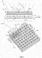
- Fig. 1 shows a generalized and greatly simplified concentrating solar power (CSP) plant 100 including a solar receiver 110 produced in accordance with an embodiment of the present invention.
- CSP plant 100 utilizes a solar concentrator (not shown) to converge sunlight beams such that concentrated solar energy E S solar energy is directed onto solar receiver 110.
- solar receiver 110 is configured to convert incident concentrated solar energy E S into thermal energy E T that is then converted into mechanical energy E M by way of heating a heat-transfer fluid 130 (e.g., water/steam or molten salt) passing through a conduit structure 114 that is part of solar receiver 110.
- the heat-transfer fluid 130 is then converted (if needed) into high temperature steam that is used to generate electricity by way of driving a steam turbine (not shown).
- At least a portion of solar receiver 110 comprises a metamaterials-enhanced sunlight-receiving surface structure 120, referred to herein as metamaterial structure 120, comprising a base material 121 having a first upward-facing surface 122 that is metamaterials-enhanced (engineered) to include substantially cube-shaped microcavities 125 and associated interlaced walls 127 forming a periodic (waffle-like) array 124 having a grating period ⁇ in the range of 0.5 to 2 microns.
- metamaterials or “metamaterial structure” generally refer to an array of structural elements (sometimes referred to as “meta-atoms”) that are arranged in repeating patterns on a base material at scales that are smaller than the wavelengths of the phenomena they are intended to influence.
- metamaterial structure 120 is implemented by integrally forming waffle-like array 124 on/into upward-facing surface 122 of base material 121, where each microcavity 125 and the associated segments of interlaced walls 127 that surround each microcavity 125 form the meta-atoms (constituent units) of metamaterial structure 120.
- metamaterials derive their optical properties not from the properties of the base materials, but from the meta-atom structures, whose precise shape, geometry, size, orientation and arrangement gives the base material the ability to manipulate electromagnetic waves to achieve benefits that cannot be achieved by the base material without the metamaterial enhancement.
- the present inventors have determined that forming waffle-like array 124 with grating period ⁇ in the range of 0.5 to 2 microns facilitates adsorption of incident solar radiation E S in the visible light spectrum with high efficiency (i.e., above 95%), and also facilitates low emission of electromagnetic radiation E R having wavelengths in the infrared spectrum, thereby minimizing radiative heat loss.
- the phrase "metamaterials-enhanced” denotes a material surface that has been subject to a photo-lithographic fabrication process or other proactive engineering process to include the surface features described herein, as opposed to surface patterns that form naturally.
- waffle-like array 124 is formed by way of removing spaced-apart sections from a substantially planar upward-facing (i.e., sunlight receiving, first) surface 122 of a sheet/block of sunlight absorbing material 121, whereby substantially cube-shaped microcavities 125 are defined through (i.e., formed by voids extending into) surface 122.
- microcavities 125 are formed in substantially planar upward-facing surface 122 by way of photo-lithographic processing (e.g., forming a mask that covers the interlaced wall sections and exposes the microcavity sections for etching).
- Interlaced walls 127 extend in parallel horizontal (X- and Y-axis) directions across upward-facing surface 122, and micro-openings 125 extend into (i.e., in the negative Z-axis direction) upward-facing surface 122, but do not pass through to lower surface 123 of surface structure 120.
- each cube-shaped microcavity 125 and its associated surrounding segments of interlaced walls 127 form one meta-atom of metamaterial structure 120.
- microcavity 125-22 and its associated surrounding wall segments form a meta-atom 124-22, which is disposed between meta-atoms 124-21 and 124-23 respectively including microcavities 125-21 and 125-23 and their respective wall segments.
- the dimensions of the microcavity opening and wall segment thickness of each meta-atom are set by grating period ⁇ (i.e., the sum of these dimensions is in the range of 0.5 to 2 microns).
- waffle-like array 124 with this grating period ⁇ has been found to greatly enhance adsorption of peak sunlight energy (i.e., sunlight having wavelengths in the visible light spectrum), and also has proven to minimize radiative thermal losses by way of suppressing the emission of electromagnetic radiation E R in the IR spectrum.
- peak sunlight energy i.e., sunlight having wavelengths in the visible light spectrum
- base material 121 consists essentially of a high melting point sunlight absorbing material.
- solar receiver 110 must be able to withstand the expected elevated temperatures (e.g., 600°C and higher).
- base material 121 is implemented using a high melting point metal (e.g., a refractory metals such as tantalum and molybdenum, which are notable for their high melting points).
- base material 121 is implemented using molybdenum because, unlike some refractory metals that are known to form relatively thick oxide layers when exposed to air, molybdenum forms a relatively thin oxide layer (i.e., having a thickness of a few nanometers) that does not adversely influence the designed optical functionality (i.e., does not skew the metamaterial dimensions), and also serves to prevent further oxidation.
- base material 121 is implemented using a non-metal material such as silicon carbide (SiC), which is known to have excellent thermal properties (e.g. low coefficient of thermal expansion, high thermal conductivity) at high temperatures.
- SiC silicon carbide
- SiC is a semiconductor, and therefore a surface structure consisting essentially of SiC may require a slightly different metamaterial geometry (i.e., different feature dimensions, discussed below) to achieve optical properties similar to those of metal-based surface structures.
- the ability to dope SiC provides a further degree freedom that may be utilized to tune the plasmonic and optical properties of the metamaterial structure.
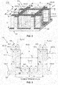
- Fig. 2 is a cut-away perspective view showing meta-atom 124-22 in additional detail. Note that Fig. 2 shows the portion of metamaterial structure 120 indicated by the dashed-line box labeled "2-2" in Fig. 1 .
- Meta-atom 124-22 generally includes wall segments 127-1 and 127-2 that extend in the Y-axis direction, wall segments 127-3 and 127-4 that extend in the X-axis direction, and horizontal bottom wall 128-22, which collectively surround and define the void region referenced as microcavity 125-22.
- the dimensions of the various features forming metamaterial structure 120 of solar receiver 110 generally coincide with wavelengths of electromagnetic radiation in the visible light spectrum.
- the exact dimensions of the metamaterial structural features determines the desired optical characteristics (e.g., absorption and emission spectra).
- solar receiver 110 By forming solar receiver 110 with metamaterial structure 120 made up of meta-atoms having feature sizes equal to or slightly outside the range of wavelengths corresponding to visible light (i.e., approximately 0.4 to approximately 1 micron), solar receiver 110 exhibits high absorptance of sunlight in the visible light spectrum, and minimizes the emission of electromagnetic radiation in the IR spectrum, thus minimizing radiative thermal loss.
- each interlaced wall 127 has a lateral (horizontal) thickness T in the range of 0.2 to 1 microns
- each microcavity 125 e.g., microcavity 125-22
- a lateral width W in the range of 0.1 to 1 micron
- a transverse (vertical) depth D in the range of 0.1 to 3 microns.
- grating period ⁇ is set at the high end of the peak resonant wavelength of incident solar energy E S (i.e., approximately 1 micron), and the exact dimensions of the structural features forming each meta-atom, which provide solar receiver 110 with the desired optical characteristics, are then numerically determined through a parametric search using finite difference time domain (FDTD), finite element method (FEM), and rigorous coupled-wave analysis (RCWA) methods. Using these methods, a corresponding reflectance can be simulated for a given metamaterial structure, from which the absorptance and emittance curves can be indirectly calculated.
- FDTD finite difference time domain
- FEM finite element method
- RCWA rigorous coupled-wave analysis
- Fig. 3 is a cross-sectional view showing meta-atom 124-22 taken along section line 3-3 of Fig. 2 , and depicts sunlight adsorption to illustrate the beneficial optical properties of metamaterial structure 120.
- the waffle-like pattern of metamaterial structure 120 forms a square-wave-type surface pattern, with upper wall surface portions 122-1 and 122-2 of wall sections 127-1 and 127-2 forming the upper level "steps" of the square-wave-type surface pattern, and microcavity bottom surfaces 128-21, 128-22 and 128-23 of microcavities 125-1, 125-2 and 125-3, respectively, forming the lower levels of the square-wave-type pattern.
- the exact dimensions of these surface features e.g., thicknesses T1 and T2 of wall sections 127-1 and 127-2, respectively, and width W of microcavity 125-22 determine the optical characteristics of metamaterial structure 120.
- metamaterial structure 120 is oriented such that incident solar radiation is directed onto waffle-like pattern 124.
- incident solar radiation portions E S1 and E S2 are respectively directed onto surface portions 122-1 and 122-2 of wall segments 127-1 and 127-2, respectively, and solar radiation portion E S3 is directed onto bottom surface 128-22 of microcavity 125-22.
- highly localized surface waves are induced by incident electromagnetic radiation and generated at interfaces between air and surface portions 122-1, 122-2 and 128-22 material, and the resonant coherent oscillations of these conduction-band electrons at these interfaces are called "surface plasmons".
- surface plasmons As indicated in Fig.
- solar radiation portions E S1 and E S2 couple to surface plasmons SP1 and SP2 at the air/surface interface defined by upper surface portions 122-1 and 122-2 of wall segments 127-1 and 127-2, respectively, and solar radiation portion E S3 couple to surface plasmon SP3 at lower surface portions 128-22. While surface plasmons SP1 to SPR3 do not respectively couple to incident radiation portions E S1 to E S3 , coupling is achieved via interlace wall segments 127-1 and 127-2 and bottom wall 128-22 that define (surround) microcavity 125-22.
- the exact feature size (dimensions) of the interlaced wall architecture and microcavity openings determine the resonant frequencies of the surface plasmonic waves generated by metamaterial structure 120. That is, unlike conventional materials, for which the permittivity and permeability are derived from the constituent atoms, the effective complex permittivity and permeability of a metamaterial is derived from each constituent unit, such as meta-atom 124-22. In other words, only incident electromagnetic radiation having intrinsic frequencies equal to these resonant frequencies of the surface plasmons will couple strongly to surface plasmonic waves SP1 to SP3. At resonance, a strong enhancement of the localized electromagnetic field is established, and electromagnetic energy is efficiently confined in metamaterial structure 120.
- the horizontal (lateral) thickness T1 of wall segment 127-1 determines the frequency of surface plasmon resonance SP1, which in turn determines the resonant frequency of solar radiation portion E S1 to which surface plasmon resonance SP1 couples, whereby solar radiation portion E S1 is converted to thermal energy (heat) E T1 that is transmitted down wall segment 127-1.
- the thickness T2 of wall segment 127-2 determines the resonant frequency of surface plasmon SP2, which in turn determines the frequency of solar radiation portion E S2 to which surface plasmon SP2 couples, whereby solar radiation portion E S2 is converted to thermal energy (heat) E T2 .
- microcavity 125-22 determines the resonant frequency of surface plasmon SP3, which in turn determines the frequency of solar radiation portion E S3 to which surface plasmon resonance SP3 couples, whereby solar radiation portion E S3 is converted to thermal energy (heat) E T3 .
- microcavity 125-22 acts as a sink for incident solar radiation ES1 to ES3, with the surface waves dissipating in the form of thermal energy E T1 to E T3 . Referring to Fig. 2 , this conversion also occurs in wall segments 127-3 and 127-4 of meta-atom 124-22.
- Fig. 4 is a graph showing an example of a modeled absorption spectrum for a metamaterial structure fabricated in the above-described waffle-like array with specification including a grating period ⁇ of 1 ⁇ m, a microcavity width W of 800 nm, and microcavity depth D of 1.6 ⁇ m, and using tantalum as the surface material.
- the terrestrial solar spectrum is also shown in Fig. 4 for comparison.
- Spectrally selective surfaces are generally characterized by exhibiting high absorptance at wavelengths below some cut-off wavelength and low absorptance above that cut-off wavelength.
- the absorptance of a surface material indicates the effectiveness in absorbing radiant energy, and is indicated as the fraction of incident electromagnetic power that is absorbed at an interface.
- the cut-off wavelength is dependent on the operating temperature and expected concentrating ratio at the receiving surface. For example, a concentrating solar photovoltaics parabolic trough receiver operating at 500°C would have a cut-off wavelength of approximately 2.5 ⁇ m.
- the peak wavelength of the black-body thermal radiation shifts to shorter wavelengths, therefore the cut-off wavelength similarly will need to be reduced.
- the absorptance for an idealized selective surface would have a cut-off wavelength of 2.5 ⁇ m.
- interlaced walls 127 have the same thickness T (as indicated in Fig. 2 ), thus generating resonances at the same frequency.
- the interlaced walls 127 are formed with different thicknesses (e.g., thicknesses T1 and T2 in Fig. 3 , where T2 > T1), thus causing the different walls to absorb solar energy at slightly different frequencies.
- solar receivers produced in accordance with the present invention either comprise integral structures or multiple-part structures.
- Fig. 5 shows a first exemplary embodiment in which metamaterial structure 120A forms an entirety of solar receiver 110A, and comprises an integrally-formed block 121A of high melting point sunlight absorbing base material (e.g., a refractory metal).
- base material e.g., a refractory metal
- heat-exchange fluid conduits 129A are bored or otherwise cut through block 121A either before or after waffle-like array 124B is formed on upward-facing surface 122A.
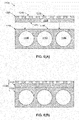
- Figs. 6(A) and 6(B) show a second exemplary embodiment in which solar receiver 110B includes a film-like structure 120B that is disposed on a block-like base section 115B.
- metamaterial structure 120B comprises a thin (foil or wafer) substrate 121B consisting essentially of a high melting point sunlight absorbing base material having upward-facing surface 122B upon which is formed a waffle-like array 124B having the features described above.
- a lower surface 123B of substrate 121B is secured to an upper surface 116B of base section 115B, which has been separately processed (e.g., machined) to include heat-exchange fluid conduits 119B.
- An advantage of the two-piece approach is that this approach simplifies processing of metamaterial structure 120B, and facilitates forming curved (e.g., pipe-like) solar receiver structures by way of bending surface structure 120B onto a curved surface of base section 115B.
- Fig. 7 shows a central receiver CSP plant 100C including a tower 105C supporting a solar receiver 110C, heliostats 141C-1 and 141C-2 form a concentrator 140C configured to concentrate incident solar energy E S onto solar receiver 110C, where solar solar receiver 110C includes a metamaterials-enhanced surface structure 120C according to any of the embodiments mentioned above, and is further configured to transfer heat energy to a heat-exchange fluid 130C that is transmitted by way of a heat-exchange fluid circulation system 150C to a turbine (not shown).
- Fig. 7 shows a central receiver CSP plant 100C including a tower 105C supporting a solar receiver 110C, heliostats 141C-1 and 141C-2 form a concentrator 140C configured to concentrate incident solar energy E S onto solar receiver 110C, where solar solar receiver 110C includes a metamaterials-enhanced surface structure 120C according to any of the embodiments mentioned above, and is further configured to transfer heat energy to a heat-exchange fluid 130C that
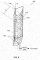
- FIG. 8 shows a solar dish CSP plant 100D including a solar dish concentrator 140D disposed on a support 144D and configured to focus solar energy E S onto a solar receiver 110D maintained by way of a central post 146D at a focal point FP, where solar receiver 110D includes a metamaterials-enhanced surface structure 120D according to any of the embodiments mentioned above, and is further configured to transfer heat energy to a heat-exchange fluid 130D.
- FIG. 9 shows a parabolic trough CSP plant 100E according to another embodiment including a trough-type concentrator 140E configured to focus solar energy E S onto a pipe-like solar receiver 110E maintained by way of a support arms 146E along a focal line FL, where solar receiver 110E includes a metamaterials-enhanced surface structure 120E according to any of the embodiments mentioned above, and is further configured to transfer heat energy to a heat-exchange fluid 130E.
- a trough-type concentrator 140E configured to focus solar energy E S onto a pipe-like solar receiver 110E maintained by way of a support arms 146E along a focal line FL
- solar receiver 110E includes a metamaterials-enhanced surface structure 120E according to any of the embodiments mentioned above, and is further configured to transfer heat energy to a heat-exchange fluid 130E.
Landscapes
- Engineering & Computer Science (AREA)
- Physics & Mathematics (AREA)
- Thermal Sciences (AREA)
- Life Sciences & Earth Sciences (AREA)
- Sustainable Development (AREA)
- Sustainable Energy (AREA)
- Chemical & Material Sciences (AREA)
- Combustion & Propulsion (AREA)
- Mechanical Engineering (AREA)
- General Engineering & Computer Science (AREA)
- Ceramic Engineering (AREA)
- Spectroscopy & Molecular Physics (AREA)
- Photovoltaic Devices (AREA)
Description
- This invention relates to solar thermal power plants, and more particularly to sunlight energy (solar) receivers utilized in solar thermal power plant.
- Concentrating Solar Power (CSP) is a renewable energy technology that utilizes solar thermal power generation to convert solar thermal energy to electricity. The solar thermal power generation process generally involves converting the solar energy into thermal energy, then converting the thermal energy into mechanical energy, and then converting the mechanical energy into electricity. CSP power plants achieve high-efficiency solar thermal power generation by way of utilizing a solar concentrator (e.g., a parabolic trough, a solar dish, or an array of mirrors) to direct concentrated sunlight onto a solar receiver (i.e., a structure comprising a sunlight absorbing material), thereby converting the solar energy into thermal energy by way of heating the solar receiver to a high operating temperature. The thermal energy is then converted into mechanical energy by way of generating high temperature steam (e.g., by forming the light absorbing material of the solar receiver into a pipe-like structure, and passing water/steam through the pipe's conduit). The high temperature steam is then directed to a turbine, whereby the mechanical energy is converted to electricity by a conventional generator driven by the turbine. Excess thermal energy is often collected in molten salts and stored in large insulated tanks, allowing operation of the steam turbine during the night or on cloudy days. CSP power plants are therefore similar to most conventional power plants that utilize heat from a fuel source to drive a stream turbine, but instead of generating heat, e.g., from the combustion of fossil fuels or another non-renewable fuel source, solar thermal power plants produce steam using sunlight.
- The evolution of CSP technology is mainly driven by the goal of achieving higher solar receiver operating temperatures, with central receiver CSP plants currently recognized as being superior in this regard over parabolic trough and solar dish CSP plants. Solar receiver operating temperatures above about 500°C, and more preferably above 600°C, are optimal for achieving high power cycle efficiency, reduce material costs for thermal storage, and lower the overall cost of electricity generated by a CSP plant. Parabolic trough CSP plants utilize elongated half-cylinder-shaped parabolic reflectors to concentrate sunlight onto line-type (pipe-like) solar receivers positioned along a focal line defined by each parabolic reflector. Because the parabolic shape focuses sunlight in only one plane, the concentration ratio of parabolic reflectors is limited to 30 to 100 times its normal intensity, whereby parabolic trough CSP plants achieve relatively low maximum operating temperatures (i.e., approximately 400 to 550°C). Solar dish CSP plants utilize a dish (bowl) shaped reflector that concentrates incident sunlight on a point-type solar receiver located at a focal point of the dish, thereby achieving higher concentration ratios than can be achieved using a parabolic trough reflector, whereby solar dish CSP plants achieving relatively high maximum operating temperatures (i.e., 600-750°C). However, the solar dish reflector must be constantly repositioned throughout the day to maintain focus of the concentrated sunlight on the solar receiver, so practical considerations associated with supporting and moving solar dishes limit their practical size and corresponding weight, thereby limiting the peak power generation capacity of solar dish CSP plants. Central receiver CSP plants utilize an array of heliostats disposed on the ground next to a tower supporting a solar receiver, where each heliostat includes a mirror and an associated positioning mechanism that repositions the mirror throughout the day to reflect incident sunlight onto the solar receiver. Similar to solar dish CSP plants, the peak power generation capacity of central receiver CSP plants is determined by the amount of sunlight reflected onto the tower-based receiver, which in both cases corresponds to the total reflective area of the mirrors. However, unlike solar dish reflectors whose practical size and weight are limiting factors, the total reflective area of a central receiver CSP system is expandable by installing additional heliostats next to the receiver tower; that is, because each heliostat is disposed on the ground and includes its own mirror positioning mechanism, expanding the reflective area of a central receiver CSP plant merely requires installing an aligning additional heliostats. Existing central receiver CSP plants collect concentrated sunlight reflected from hundreds or thousands of heliostats to achieve concentration ratios as high as 1,500 times the sun's normal intensity, and maximum operating temperatures well above 750°C. Central receiver CSP plants are therefore capable of achieving substantially higher solar receiver operating temperatures than parabolic trough and solar dish CSP plants, and hence are currently the preferred CSP plant technology for large volume electricity generation.
- Although advances in CSP technology facilitate the generation of optimal solar receiver operating temperatures (i.e., above about 600°C), a current limiting factor to further advances in CSP technology is the inability of presently available sunlight absorbing materials to absorb solar energy with high efficiency at these temperatures. As mentioned above, a solar receiver is a structure consisting of a sunlight absorbing material that is configured to transfer absorbed heat to a heat transfer fluid (e.g., molten salt or water/steam). A solar receiver's efficiency is defined by the amount of received solar energy that is absorbed/transferred to the heat transfer fluid versus the amount of received solar energy that is lost due to convective heat losses (e.g., due to wind and buoyancy effects) and radiative heat losses (i.e., as materials get hot, heat energy is radiated away at infrared wavelengths to the surrounding environment). At a 600°C operating temperature, the primary cause of heat loss from CSP plant's solar receiver is thermal radiation losses, and the rate of radiative heat loss increases as operating temperatures increase above 600°C. Therefore, although central receiver CSP plants are capable of achieving operating temperatures well above 600°C, radiative heat loss from solar receivers at higher operating temperatures limits the overall efficiency of a central receiver CSP plant operating at higher temperatures.
- Current efforts to reduce radiative heat loss from solar receivers operating above 600°C are focused on developing spectrally-selective coatings that are painted or otherwise applied to the solar receiver's "core" sunlight absorbing material. These coatings are formulated to maximize solar absorptance in the visible and near-infrared wavelengths (i.e., approximately 400 to 2500 nm) while minimizing thermal emittance in the infrared wavelengths (i.e., approximately 1 to 20 microns). Because these spectra overlap, especially at higher temperatures, development of selective coatings is challenging. Additionally, these selective absorber coatings need to be durable at high temperatures in exposed environments to avoid degradation. Currently, Pyromark® Series 2500 Flat Black (LA-CO Industries Inc., Elk Grove Village, IL, USA), which is a high temperature resistant silicone coating exhibiting high solar absorptance (>95%), has been recognized by Sandia National Laboratories as a standard for use on solar receivers in central receiver CSP plants (see Levelized Cost of Coating (LCOC) for Selective Absorber Materials, Clifford K. Ho and James E. Pacheco, SANDIA REPORT SAND2013-8327, Printed September 2013). However, Pyromark® Series 2500 also exhibits a thermal emittance of 0.87 and suffers from large thermal losses during high temperature operation, and also exhibited significant degradation at higher temperatures (>700°C) when operated in air, causing a decline in performance and potentially added operating costs for CSP plants. Further, the coating-based approach suffers from inherent delamination issues due to the unavoidable differences between the coating material and the underlying sunlight absorbing "core" material forming the solar receiver, and the coating material re-emits in the IR, which lowers thermal efficiency.
- What is needed is a solar receiver that exhibits high absorptance (i.e., >95%) and low thermal emittance (i.e., < 10%) of solar energy at operating temperatures above 600°C, and also avoids the problems associated with conventional coatings-based approaches.
-
JP 2003 332607 A claim 1. - The present invention is directed to a solar receiver including a metamaterials-enhanced sunlight receiving surface structure (metamaterial structure) consisting essentially of a high melting point sunlight absorbing material having an upward-facing (sunlight receiving) surface that is photo-lithographically processed or otherwise fabricated (engineered) to define substantially cube-shaped microcavities surrounded by associated parallel interlaced walls that are arranged in a periodic waffle-like array having a grating period in the range of 0.5 to 2 microns, wherein two or more of the interlaced walls have different thicknesses. By processing the sunlight receiving surface to produce the waffle-like array with a grating period in the range of 0.5 to 2 microns, the microcavities and interlaced walls have feature sizes that enhance the generation of surface plasmons primarily resonating at visible light frequencies, whereby the metamaterial structure achieves high absorptance efficiency (i.e., >95%) of sunlight in the visible light spectrum and low thermal emittance (i.e., < 10%) in the infrared (IR) spectrum. By forming the metamaterial structure on a solar energy absorbing material having suitable high melting point and low coefficient of thermal expansion at high temperatures (i.e., above 600°C), the metamaterial structure reliably maintains the surface features of the waffle-like array at the high solar receiver operating temperatures achieved in a CSP plant. Moreover, because the metamaterial structure consists entirely of the waffle-like array fabricated directly into the upward-facing surface of the high melting point solar energy absorbing material (i.e., no coating is applied to the upward-facing surface), the present invention avoids the delamination issue associated with prior art coatings-based solar receiver approaches, thereby providing solar receivers that are optimized for use in CSP plants.
- According to alternative specific embodiments of the invention, the high melting point sunlight absorbing material utilized to produce the metamaterials-enhanced surface structure consists essentially of one or more refractory metals (e.g., tantalum or molybdenum) or silicon carbide (SiC). These high melting point solar energy absorbing materials are presently preferred in that they exhibit excellent thermal properties (e.g., low coefficient of thermal expansion and high thermal conductivity) and supports surface plasmon generation at temperatures above 600°C, whereby the metamaterial structure of the present invention facilitates the fabrication of solar receivers for CSP plants that avoid the degradation problems associated with conventional coatings-based approaches. Moreover, because the present invention is not composition-dependent (i.e., the optical characteristics are not limited to a particular composition or particle size), the metamaterials-enhanced solution of the present invention is applicable to yet undiscovered melting point solar energy absorbing materials capable of maintaining optimal optical characteristics at even higher temperatures, whereby the present invention is theoretically applicable to any achievable CSP plant operating temperature.
- According to other specific embodiments of the invention, the feature dimensions of the waffle-like array are optimized to enhance the spectrally-selective optical characteristics of the metamaterial structure. In one embodiment, each of the interlaced walls has a thickness in the range of 0.2 to 1.0 microns, and each microcavity of the plurality of microcavities has a width in the range of 0.1 to 1 micron and a depth in the range of 0.1 to 3 microns, which facilitates the generation of surface plasmonic waves resonating at visible light frequencies. According to the invention, two or more of the interlaced walls have different thicknesses to further enhance the adsorption of sunlight in the visible light spectrum.
- In alternative embodiments, metamaterials-enhanced solar receivers of the present invention are constructed either as a single-piece (integral) unit or multiple-part assembly. According to the single-piece approach, the entirety of the solar receiver includes an integral block of high melting point sunlight absorbing base material upon which the metamaterial structure is formed (i.e., with the waffle-like array is formed on an upward-facing surface of the block), and heat-exchange fluid conduits are machined into the block below the upward-facing surface. An advantage of the single-piece approach is that utilizing a single material block precludes the possibility of delamination, which is a problem with coatings-based approaches. According to the multiple-part approach, the solar receiver includes a thin (e.g., wafer- or foil-like) sheet of high melting point sunlight absorbing base material upon which the metamaterial structure is formed, and then the wafer-like sheet is operably secured to a block-type base section. An advantage of the two-piece approach is that forming the waffle-like array on a thin wafer-like structure simplifies the metamaterials engineering process because it facilitates using existing semiconductor processing equipment with minimal modifications. Another advantage of the two-piece approach is that it facilitates the efficient formation of curved (e.g., pipe-like) solar receiver structures by way of forming the metamaterial structure on a flexible foil-like sheet, and then press-forming the foil-like sheet such that it contours to a curved surface formed on the base section.
- According to another embodiment of the present invention, a CSP plant includes a solar concentrator configured to concentrate incident solar energy onto a solar receiver for conversion into thermal energy passed to a heat transfer fluid with high efficiency, wherein the solar receiver includes a metamaterials-enhanced surface structure configured in accordance with any of the embodiments described above. In a preferred embodiment, the solar receiver is disposed on a tower, and the solar concentrator includes multiple ground-based heliostats having flat mirrors that respectively reflect sunlight onto the metamaterials-enhanced surface structure. In alternative embodiments, the solar concentrator is implemented by a solar dish or a parabolic trough.
- These and other features, aspects and advantages of the present invention will become better understood with regard to the following description, appended claims, and accompanying drawings, where:
-
Fig. 1 is a cross-sectional side and partial perspective views showing a simplified solar receiver including a metamaterial structure according to a simplified embodiment of the present invention; -
Fig. 2 is a cut-away top side perspective view showing an enlarged microcavity and surrounding interlaced walls that form a meta-atom of the metamaterial structure ofFig. 1 ; -
Fig. 3 is cross-sectional side view showing the meta-atom ofFig. 2 in additional detail; -
Fig. 4 is a graph showing a modeled absorption spectrum for an exemplary metamaterial structure; -
Figs. 5 is a simplified cross-sectional side view showing a one-piece solar receiver according to a first exemplary embodiment of the present invention; -
Figs. 6(A) and 6(B) are exploded and assembled cross-sectional side views showing showing a two-piece solar receiver according to a second exemplary embodiment of the present invention; -
Fig. 7 is a perspective side view showing a simplified central receiver CSP plant including a solar receiver according to another embodiment of the present invention; -
Fig. 8 is a perspective side view showing a simplified solar dish CSP plant including a solar receiver according to another embodiment of the present invention; and -
Fig. 9 is a perspective side view showing a simplified solar trough CSP plant including a solar receiver according to another embodiment of the present invention. - The present invention relates to improved solar receivers for CSP plants. The following description is presented to enable one of ordinary skill in the art to make and use the invention as provided in the context of a particular application and its requirements. As used herein, directional terms such as "upper", "upward-facing", "lower", "horizontal" and "downward" are intended to provide relative positions for purposes of description, and are not intended to designate an absolute frame of reference. In addition, the phrases "integral" and "integrally formed" are used herein to describe the connective relationship between two portions of a single molded or machined structure, and are distinguished from the terms "connected" or "coupled" (without the modifier "integrally"), which indicate two separate structures that are joined by way of, for example, adhesive, fastener, clip, or movable joint. Various modifications to the preferred embodiment will be apparent to those with skill in the art, and the general principles defined herein may be applied to other embodiments. Therefore, the present invention is not intended to be limited to the particular embodiments shown and described, but is to be accorded the widest scope consistent with the principles and novel features herein disclosed.
-
Fig. 1 shows a generalized and greatly simplified concentrating solar power (CSP)plant 100 including asolar receiver 110 produced in accordance with an embodiment of the present invention.CSP plant 100 utilizes a solar concentrator (not shown) to converge sunlight beams such that concentrated solar energy ES solar energy is directed ontosolar receiver 110. Similar to conventional solar receivers,solar receiver 110 is configured to convert incident concentrated solar energy ES into thermal energy ET that is then converted into mechanical energy EM by way of heating a heat-transfer fluid 130 (e.g., water/steam or molten salt) passing through aconduit structure 114 that is part ofsolar receiver 110. The heat-transfer fluid 130 is then converted (if needed) into high temperature steam that is used to generate electricity by way of driving a steam turbine (not shown). - According to a novel aspect of the invention, at least a portion of
solar receiver 110 comprises a metamaterials-enhanced sunlight-receivingsurface structure 120, referred to herein asmetamaterial structure 120, comprising abase material 121 having a first upward-facingsurface 122 that is metamaterials-enhanced (engineered) to include substantially cube-shapedmicrocavities 125 and associated interlacedwalls 127 forming a periodic (waffle-like)array 124 having a grating period Λ in the range of 0.5 to 2 microns. As known to those skilled in the art, the terms "metamaterials" or "metamaterial structure" generally refer to an array of structural elements (sometimes referred to as "meta-atoms") that are arranged in repeating patterns on a base material at scales that are smaller than the wavelengths of the phenomena they are intended to influence. Using this definition,metamaterial structure 120 is implemented by integrally forming waffle-like array 124 on/into upward-facingsurface 122 ofbase material 121, where eachmicrocavity 125 and the associated segments of interlacedwalls 127 that surround eachmicrocavity 125 form the meta-atoms (constituent units) ofmetamaterial structure 120. Note that metamaterials derive their optical properties not from the properties of the base materials, but from the meta-atom structures, whose precise shape, geometry, size, orientation and arrangement gives the base material the ability to manipulate electromagnetic waves to achieve benefits that cannot be achieved by the base material without the metamaterial enhancement. In this case, the present inventors have determined that forming waffle-like array 124 with grating period Λ in the range of 0.5 to 2 microns facilitates adsorption of incident solar radiation ES in the visible light spectrum with high efficiency (i.e., above 95%), and also facilitates low emission of electromagnetic radiation ER having wavelengths in the infrared spectrum, thereby minimizing radiative heat loss. As used herein, the phrase "metamaterials-enhanced" denotes a material surface that has been subject to a photo-lithographic fabrication process or other proactive engineering process to include the surface features described herein, as opposed to surface patterns that form naturally. - An exemplary portion of
metamaterial structure 120, which is greatly simplified and greatly enlarged form for explanatory purposes, is depicted at the lower portion ofFig. 1 . In one embodiment, waffle-like array 124 is formed by way of removing spaced-apart sections from a substantially planar upward-facing (i.e., sunlight receiving, first)surface 122 of a sheet/block ofsunlight absorbing material 121, whereby substantially cube-shapedmicrocavities 125 are defined through (i.e., formed by voids extending into)surface 122. The removed spaced-apart sections are aligned in rows and columns, whereby remaining (i.e., un-etched) sections ofmaterial 121 form interlacedwalls 127 that separateadjacent microcavities 125, and the remaining portions of upward-facingsurface 122 forming upper (horizontal) surfaces of interlacedwalls 127. In one embodiment,microcavities 125 are formed in substantially planar upward-facingsurface 122 by way of photo-lithographic processing (e.g., forming a mask that covers the interlaced wall sections and exposes the microcavity sections for etching). Interlacedwalls 127 extend in parallel horizontal (X- and Y-axis) directions across upward-facingsurface 122, and micro-openings 125 extend into (i.e., in the negative Z-axis direction) upward-facingsurface 122, but do not pass through tolower surface 123 ofsurface structure 120. - As mentioned above, each cube-shaped
microcavity 125 and its associated surrounding segments of interlacedwalls 127 form one meta-atom ofmetamaterial structure 120. For example, as indicated in the lower portion ofFig. 1 , microcavity 125-22 and its associated surrounding wall segments form a meta-atom 124-22, which is disposed between meta-atoms 124-21 and 124-23 respectively including microcavities 125-21 and 125-23 and their respective wall segments. To providesolar receiver 110 with the desired optical characteristics, the dimensions of the microcavity opening and wall segment thickness of each meta-atom are set by grating period Λ (i.e., the sum of these dimensions is in the range of 0.5 to 2 microns). As explained in additional detail below, forming waffle-like array 124 with this grating period Λ has been found to greatly enhance adsorption of peak sunlight energy (i.e., sunlight having wavelengths in the visible light spectrum), and also has proven to minimize radiative thermal losses by way of suppressing the emission of electromagnetic radiation ER in the IR spectrum. - According to another aspect of the present invention,
base material 121 consists essentially of a high melting point sunlight absorbing material. In addition to providing the desired spectrally selective optical characteristics,solar receiver 110 must be able to withstand the expected elevated temperatures (e.g., 600°C and higher). Accordingly, in one embodiment,base material 121 is implemented using a high melting point metal (e.g., a refractory metals such as tantalum and molybdenum, which are notable for their high melting points). In a currently preferred refractory metal embodiment,base material 121 is implemented using molybdenum because, unlike some refractory metals that are known to form relatively thick oxide layers when exposed to air, molybdenum forms a relatively thin oxide layer (i.e., having a thickness of a few nanometers) that does not adversely influence the designed optical functionality (i.e., does not skew the metamaterial dimensions), and also serves to prevent further oxidation. In another embodiment,base material 121 is implemented using a non-metal material such as silicon carbide (SiC), which is known to have excellent thermal properties (e.g. low coefficient of thermal expansion, high thermal conductivity) at high temperatures. Unlike metals, SiC is a semiconductor, and therefore a surface structure consisting essentially of SiC may require a slightly different metamaterial geometry (i.e., different feature dimensions, discussed below) to achieve optical properties similar to those of metal-based surface structures. The ability to dope SiC provides a further degree freedom that may be utilized to tune the plasmonic and optical properties of the metamaterial structure. -
Fig. 2 is a cut-away perspective view showing meta-atom 124-22 in additional detail. Note thatFig. 2 shows the portion ofmetamaterial structure 120 indicated by the dashed-line box labeled "2-2" inFig. 1 . Meta-atom 124-22 generally includes wall segments 127-1 and 127-2 that extend in the Y-axis direction, wall segments 127-3 and 127-4 that extend in the X-axis direction, and horizontal bottom wall 128-22, which collectively surround and define the void region referenced as microcavity 125-22. - According to a specific embodiment of the present invention, the dimensions of the various features forming
metamaterial structure 120 ofsolar receiver 110 generally coincide with wavelengths of electromagnetic radiation in the visible light spectrum. As set forth above, the exact dimensions of the metamaterial structural features determines the desired optical characteristics (e.g., absorption and emission spectra). By formingsolar receiver 110 withmetamaterial structure 120 made up of meta-atoms having feature sizes equal to or slightly outside the range of wavelengths corresponding to visible light (i.e., approximately 0.4 to approximately 1 micron),solar receiver 110 exhibits high absorptance of sunlight in the visible light spectrum, and minimizes the emission of electromagnetic radiation in the IR spectrum, thus minimizing radiative thermal loss. In one embodiment, each interlacedwall 127 has a lateral (horizontal) thickness T in the range of 0.2 to 1 microns, and each microcavity 125 (e.g., microcavity 125-22) has a lateral width W in the range of 0.1 to 1 micron, and a transverse (vertical) depth D in the range of 0.1 to 3 microns. In one embodiment, grating period Λ is set at the high end of the peak resonant wavelength of incident solar energy ES (i.e., approximately 1 micron), and the exact dimensions of the structural features forming each meta-atom, which providesolar receiver 110 with the desired optical characteristics, are then numerically determined through a parametric search using finite difference time domain (FDTD), finite element method (FEM), and rigorous coupled-wave analysis (RCWA) methods. Using these methods, a corresponding reflectance can be simulated for a given metamaterial structure, from which the absorptance and emittance curves can be indirectly calculated. -
Fig. 3 is a cross-sectional view showing meta-atom 124-22 taken along section line 3-3 ofFig. 2 , and depicts sunlight adsorption to illustrate the beneficial optical properties ofmetamaterial structure 120. Note that, in cross-section, the waffle-like pattern ofmetamaterial structure 120 forms a square-wave-type surface pattern, with upper wall surface portions 122-1 and 122-2 of wall sections 127-1 and 127-2 forming the upper level "steps" of the square-wave-type surface pattern, and microcavity bottom surfaces 128-21, 128-22 and 128-23 of microcavities 125-1, 125-2 and 125-3, respectively, forming the lower levels of the square-wave-type pattern. As indicated below, the exact dimensions of these surface features (e.g., thicknesses T1 and T2 of wall sections 127-1 and 127-2, respectively, and width W of microcavity 125-22) determine the optical characteristics ofmetamaterial structure 120. - As depicted in
Fig. 3 , duringoperation metamaterial structure 120 is oriented such that incident solar radiation is directed onto waffle-like pattern 124. In the depicted example, incident solar radiation portions ES1 and ES2 are respectively directed onto surface portions 122-1 and 122-2 of wall segments 127-1 and 127-2, respectively, and solar radiation portion ES3 is directed onto bottom surface 128-22 of microcavity 125-22. Under these conditions, highly localized surface waves are induced by incident electromagnetic radiation and generated at interfaces between air and surface portions 122-1, 122-2 and 128-22 material, and the resonant coherent oscillations of these conduction-band electrons at these interfaces are called "surface plasmons". As indicated inFig. 3 , solar radiation portions ES1 and ES2 couple to surface plasmons SP1 and SP2 at the air/surface interface defined by upper surface portions 122-1 and 122-2 of wall segments 127-1 and 127-2, respectively, and solar radiation portion ES3 couple to surface plasmon SP3 at lower surface portions 128-22. While surface plasmons SP1 to SPR3 do not respectively couple to incident radiation portions ES1 to ES3, coupling is achieved via interlace wall segments 127-1 and 127-2 and bottom wall 128-22 that define (surround) microcavity 125-22. - As mentioned above, the exact feature size (dimensions) of the interlaced wall architecture and microcavity openings determine the resonant frequencies of the surface plasmonic waves generated by
metamaterial structure 120. That is, unlike conventional materials, for which the permittivity and permeability are derived from the constituent atoms, the effective complex permittivity and permeability of a metamaterial is derived from each constituent unit, such as meta-atom 124-22. In other words, only incident electromagnetic radiation having intrinsic frequencies equal to these resonant frequencies of the surface plasmons will couple strongly to surface plasmonic waves SP1 to SP3. At resonance, a strong enhancement of the localized electromagnetic field is established, and electromagnetic energy is efficiently confined inmetamaterial structure 120. In this case, the horizontal (lateral) thickness T1 of wall segment 127-1 determines the frequency of surface plasmon resonance SP1, which in turn determines the resonant frequency of solar radiation portion ES1 to which surface plasmon resonance SP1 couples, whereby solar radiation portion ES1 is converted to thermal energy (heat) ET1 that is transmitted down wall segment 127-1. Similarly, the thickness T2 of wall segment 127-2 determines the resonant frequency of surface plasmon SP2, which in turn determines the frequency of solar radiation portion ES2 to which surface plasmon SP2 couples, whereby solar radiation portion ES2 is converted to thermal energy (heat) ET2. Moreover, the width W of microcavity 125-22 determines the resonant frequency of surface plasmon SP3, which in turn determines the frequency of solar radiation portion ES3 to which surface plasmon resonance SP3 couples, whereby solar radiation portion ES3 is converted to thermal energy (heat) ET3. In this way, microcavity 125-22 acts as a sink for incident solar radiation ES1 to ES3, with the surface waves dissipating in the form of thermal energy ET1 to ET3. Referring toFig. 2 , this conversion also occurs in wall segments 127-3 and 127-4 of meta-atom 124-22.Engineering metamaterial structure 120 to have resonances primarily (if not exclusively) in the visible regime (i.e., not in the IR regime) of the spectrum will result in an absorption spectrum close to the ideal absorber target.Fig. 4 is a graph showing an example of a modeled absorption spectrum for a metamaterial structure fabricated in the above-described waffle-like array with specification including a grating period Λ of 1 µm, a microcavity width W of 800 nm, and microcavity depth D of 1.6 µm, and using tantalum as the surface material. The terrestrial solar spectrum is also shown inFig. 4 for comparison. - In addition to exhibiting high absorptance efficiency, metamaterial structures formed in accordance with the above description minimizes radiative thermal losses by way of exhibiting spectral selectivity to visible light. Spectrally selective surfaces are generally characterized by exhibiting high absorptance at wavelengths below some cut-off wavelength and low absorptance above that cut-off wavelength. The absorptance of a surface material indicates the effectiveness in absorbing radiant energy, and is indicated as the fraction of incident electromagnetic power that is absorbed at an interface. The cut-off wavelength is dependent on the operating temperature and expected concentrating ratio at the receiving surface. For example, a concentrating solar photovoltaics parabolic trough receiver operating at 500°C would have a cut-off wavelength of approximately 2.5 µm. At higher temperatures, the peak wavelength of the black-body thermal radiation shifts to shorter wavelengths, therefore the cut-off wavelength similarly will need to be reduced. For the known solar spectrum at the earth's surface, assuming black-body radiation for temperatures above about 600°C, the absorptance for an idealized selective surface would have a cut-off wavelength of 2.5 µm.
- Referring again to
Figs. 2 and 3 , in an example that does not fall under the scope of the invention, interlacedwalls 127 have the same thickness T (as indicated inFig. 2 ), thus generating resonances at the same frequency. According to the invention, the interlacedwalls 127 are formed with different thicknesses (e.g., thicknesses T1 and T2 inFig. 3 , where T2 > T1), thus causing the different walls to absorb solar energy at slightly different frequencies. - According to additional alternative embodiments, solar receivers produced in accordance with the present invention either comprise integral structures or multiple-part structures.
-
Fig. 5 shows a first exemplary embodiment in whichmetamaterial structure 120A forms an entirety ofsolar receiver 110A, and comprises an integrally-formed block 121A of high melting point sunlight absorbing base material (e.g., a refractory metal). In this example, heat-exchange fluid conduits 129A are bored or otherwise cut through block 121A either before or after waffle-like array 124B is formed on upward-facingsurface 122A. An advantage of the single-piece approach is that this precludes the possibility of delamination. -
Figs. 6(A) and 6(B) show a second exemplary embodiment in whichsolar receiver 110B includes a film-like structure 120B that is disposed on a block-like base section 115B. In this case,metamaterial structure 120B comprises a thin (foil or wafer) substrate 121B consisting essentially of a high melting point sunlight absorbing base material having upward-facingsurface 122B upon which is formed a waffle-like array 124B having the features described above. In this case, a lower surface 123B of substrate 121B is secured to anupper surface 116B ofbase section 115B, which has been separately processed (e.g., machined) to include heat-exchange fluid conduits 119B. An advantage of the two-piece approach is that this approach simplifies processing ofmetamaterial structure 120B, and facilitates forming curved (e.g., pipe-like) solar receiver structures by way of bendingsurface structure 120B onto a curved surface ofbase section 115B. - The various solar receivers described above may be utilized to provide various different CSP plants. For example,
Fig. 7 shows a central receiver CSP plant 100C including a tower 105C supporting a solar receiver 110C,heliostats 141C-1 and 141C-2 form aconcentrator 140C configured to concentrate incident solar energy ES onto solar receiver 110C, where solar solar receiver 110C includes a metamaterials-enhancedsurface structure 120C according to any of the embodiments mentioned above, and is further configured to transfer heat energy to a heat-exchange fluid 130C that is transmitted by way of a heat-exchangefluid circulation system 150C to a turbine (not shown). Alternatively,Fig. 8 shows a solardish CSP plant 100D including asolar dish concentrator 140D disposed on asupport 144D and configured to focus solar energy ES onto asolar receiver 110D maintained by way of acentral post 146D at a focal point FP, wheresolar receiver 110D includes a metamaterials-enhancedsurface structure 120D according to any of the embodiments mentioned above, and is further configured to transfer heat energy to a heat-exchange fluid 130D.Fig. 9 shows a parabolictrough CSP plant 100E according to another embodiment including a trough-type concentrator 140E configured to focus solar energy ES onto a pipe-likesolar receiver 110E maintained by way of asupport arms 146E along a focal line FL, wheresolar receiver 110E includes a metamaterials-enhancedsurface structure 120E according to any of the embodiments mentioned above, and is further configured to transfer heat energy to a heat-exchange fluid 130E. - Although the present invention has been described with respect to certain specific embodiments, it will be clear to those skilled in the art that the inventive features of the present invention are applicable to other embodiments as well, all of which are intended to fall within the scope of the invention as defined by the appended claims.
Claims (10)
- A solar receiver (110) comprising a metamaterials-enhanced sunlight-receiving structure (120) consisting essentially of a high melting point base material (121) having a first surface (122) comprising a plurality of substantially cube-shaped microcavities (125) surrounded by associated interlaced walls (127) that are disposed a periodic array (124) having a grating period in the range of 0.5 to 2 microns, characterised in that two or more of the interlaced walls have different thicknesses.
- The solar receiver of Claim 1, wherein said high melting point base material comprises one of a refractory metal and silicon carbide.
- The solar receiver of Claim 1, wherein each wall of said associated interlaced walls (127) has a thickness in the range of 0.2 to 1.0 microns.
- The solar receiver of Claim 3, wherein each microcavity of the plurality of microcavities (125) has a width in the range of 0.1 to 1 micron, and a depth in the range of 0.1 to 3 microns.
- A solar receiver (110) including a metamaterial structure (120) comprising a high melting point base material (121) having a first surface (122), wherein the first surface defines a plurality of substantially cube-shaped microcavities (125) disposed in a periodic array (124) between parallel interlaced walls (127), wherein each wall of said interlaced walls has a lateral thickness in the range of 0.1 to 1 micron.
- The solar receiver of Claim 5, wherein said high melting point material (121) comprises one of a refractory metal and silicon carbide.
- The solar receiver of Claim 5, wherein each microcavity of the plurality of microcavities (125) has a width in the range of 0.1 to 1 micron, and a depth in the range of 0.1 to 3 microns.
- A concentrating solar power (CSP) plant (100) comprising:a solar receiver according to claim 1 and configured to transfer heat energy to a heat-exchange fluid; anda solar concentrator (140C) configured to concentrate incident solar energy onto said solar receiver.
- The CSP plant according to Claim 8, wherein said solar concentrator (140C) comprises one of a solar dish and a parabolic trough.
- The CSP plant according to Claim 8 further comprising a central tower (105C) supporting said solar receiver (110C), wherein said solar concentrator (140C) comprises a plurality of heliostats.
Applications Claiming Priority (1)
| Application Number | Priority Date | Filing Date | Title |
|---|---|---|---|
| US14/969,139 US10288323B2 (en) | 2015-12-15 | 2015-12-15 | Solar receiver with metamaterials-enhanced solar light absorbing structure |
Publications (2)
| Publication Number | Publication Date |
|---|---|
| EP3182033A1 EP3182033A1 (en) | 2017-06-21 |
| EP3182033B1 true EP3182033B1 (en) | 2019-08-07 |
Family
ID=57544232
Family Applications (1)
| Application Number | Title | Priority Date | Filing Date |
|---|---|---|---|
| EP16202547.2A Active EP3182033B1 (en) | 2015-12-15 | 2016-12-06 | Solar receiver with metamaterials-enhanced solar light absorbing structure |
Country Status (3)
| Country | Link |
|---|---|
| US (1) | US10288323B2 (en) |
| EP (1) | EP3182033B1 (en) |
| JP (1) | JP6712541B2 (en) |
Families Citing this family (10)
| Publication number | Priority date | Publication date | Assignee | Title |
|---|---|---|---|---|
| AU2017418693B2 (en) * | 2017-06-12 | 2023-07-13 | Solight Ltd. | Radiation collector and method of manufacture thereof |
| JP7019170B2 (en) * | 2017-10-26 | 2022-02-15 | 国立大学法人大阪大学 | Plasmonic structure |
| CN109524790B (en) * | 2018-11-06 | 2020-05-05 | 北京大学 | Artificial surface plasmon radiator based on F-P cavity loading and control method |
| FR3097305B1 (en) * | 2019-06-13 | 2022-07-29 | News | Solar hybrid high efficiency thermodynamic device and hydrogen-oxygen couple producing a plurality of energies |
| EP3990837B1 (en) * | 2019-06-26 | 2024-06-05 | University of Houston System | Systems and methods for full spectrum solar thermal energy harvesting and storage by molecular and phase change material hybrids |
| CN110687065B (en) * | 2019-09-17 | 2021-08-27 | 中国科学院上海微系统与信息技术研究所 | Preparation method of infrared light source and infrared gas sensor |
| CN110763654B (en) * | 2019-11-29 | 2023-03-17 | 江西师范大学 | Inclined high-quality optical sensor and preparation method thereof |
| JP7197754B2 (en) * | 2021-03-24 | 2022-12-28 | 防衛装備庁長官 | radio wave absorber |
| CN113307322B (en) * | 2021-06-15 | 2022-07-29 | 桂林电子科技大学 | Solar evaporator based on plasmon effect |
| CN113394571B (en) * | 2021-07-20 | 2022-06-10 | 合肥工业大学 | Interdigital stepped resonance structure and wave absorber of low-frequency electromagnetic wave |
Citations (2)
| Publication number | Priority date | Publication date | Assignee | Title |
|---|---|---|---|---|
| US4065592A (en) * | 1976-04-14 | 1977-12-27 | Hercules Incorporated | Solar energy absorber |
| EP1688684A1 (en) * | 2005-01-12 | 2006-08-09 | Sgl Carbon Ag | Absorber part for a solarthermical flat type collector |
Family Cites Families (76)
| Publication number | Priority date | Publication date | Assignee | Title |
|---|---|---|---|---|
| US1111239A (en) | 1914-04-16 | 1914-09-22 | Henry D Smelser | Device for concentrating the rays of the sun. |
| US2712772A (en) | 1952-07-24 | 1955-07-12 | Ceutre Nat De La Rech Scient | Self-regulating automatic heliostat reflecting mirror device |
| US3905352A (en) | 1973-08-31 | 1975-09-16 | Arnold Jahn | System for collecting and transferring usable solar heat |
| US3892433A (en) | 1973-09-21 | 1975-07-01 | Martin Marietta Corp | Direct solar hydro-electric integrated system and concentrating heliostat for same |
| US3923381A (en) | 1973-12-28 | 1975-12-02 | Univ Chicago | Radiant energy collection |
| US3861379A (en) | 1974-03-05 | 1975-01-21 | Jr Henry Anderson | Low profile solar ray concentrator |
| US3924604A (en) | 1974-05-31 | 1975-12-09 | Schjeldahl Co G T | Solar energy conversion system |
| US4218114A (en) | 1975-12-19 | 1980-08-19 | Bunch Jesse C | Heliostat apparatus |
| US4110009A (en) | 1975-12-19 | 1978-08-29 | Bunch Jesse C | Heliostat apparatus |
| US4068653A (en) | 1976-03-01 | 1978-01-17 | Leo Bourdon | Solar heating unit |
| US4114596A (en) | 1976-03-16 | 1978-09-19 | Chang Wei Yi | Method and apparatus for tracking the sun for use in a solar collector with linear focusing means |
| CH612541A5 (en) | 1976-05-06 | 1979-07-31 | Fraunhofer Ges Forschung | |
| US4117682A (en) | 1976-11-01 | 1978-10-03 | Smith Otto J M | Solar collector system |
| US4109638A (en) | 1977-04-04 | 1978-08-29 | Matlock William C | Solar energy converter carousel |
| US4110010A (en) | 1977-07-07 | 1978-08-29 | Hilton Richard D | Ganged heliostat |
| US4149902A (en) | 1977-07-27 | 1979-04-17 | Eastman Kodak Company | Fluorescent solar energy concentrator |
| US4148301A (en) | 1977-09-26 | 1979-04-10 | Cluff C Brent | Water-borne rotating solar collecting and storage systems |
| US4130109A (en) | 1977-11-25 | 1978-12-19 | Brueck Chris M | Solar energy concentrator |
| US4153813A (en) | 1978-06-19 | 1979-05-08 | Atlantic Richfield Company | Luminescent solar collector |
| US4193819A (en) | 1978-06-23 | 1980-03-18 | Atlantic Richfield Company | Luminescent photovoltaic solar collector |
| US4234352A (en) | 1978-07-26 | 1980-11-18 | Electric Power Research Institute, Inc. | Thermophotovoltaic converter and cell for use therein |
| US4261335A (en) | 1978-10-16 | 1981-04-14 | Balhorn Alan C | Solar energy apparatus |
| US4190465A (en) | 1978-11-13 | 1980-02-26 | Owens-Illinois, Inc. | Luminescent solar collector structure |
| US4266530A (en) | 1979-09-27 | 1981-05-12 | Steadman Robert W | Sun ray tracker |
| DE3205439A1 (en) | 1981-03-02 | 1983-08-25 | Imchemie Kunststoff Gmbh, 5632 Wermelskirchen | Solar concentrator having concave mirrors |
| DE3107888A1 (en) | 1981-03-02 | 1982-09-16 | Imchemie Kunststoff Gmbh, 5632 Wermelskirchen | SOLAR CONCENTRATOR |
| US4771764A (en) | 1984-04-06 | 1988-09-20 | Cluff C Brent | Water-borne azimuth-altitude tracking solar concentrators |
| DE3633172A1 (en) | 1986-09-30 | 1988-04-07 | Man Technologie Gmbh | Method for utilising solar energy and apparatus for carrying out the method |
| GB8629283D0 (en) | 1986-12-08 | 1987-01-14 | Gen Electric Co Plc | Radiation meters |
| US5180441A (en) | 1991-06-14 | 1993-01-19 | General Dynamics Corporation/Space Systems Division | Solar concentrator array |
| US5274497A (en) | 1991-11-29 | 1993-12-28 | Casey Paul A | Concentrating collector lens assembly |
| US5288337A (en) | 1992-06-25 | 1994-02-22 | Siemens Solar Industries, L.P. | Photovoltaic module with specular reflector |
| US5816238A (en) | 1994-11-28 | 1998-10-06 | Minnesota Mining And Manufacturing Company | Durable fluorescent solar collectors |
| US6239353B1 (en) | 1998-10-14 | 2001-05-29 | Christopher M. Hall | Solar tracker |
| AU2001249256A1 (en) | 2000-03-16 | 2001-09-24 | Pablo Benitez | High efficiency non-imaging optics |
| DE10025212A1 (en) | 2000-05-22 | 2001-11-29 | Andreas Noehrig | Solar energy concentrator with tracking parabolic reflector, has lower edge adjacent to support plane and pivotal axis |
| US6820611B2 (en) | 2000-11-10 | 2004-11-23 | Mikio Kinoshita | Solar radiation concentrator and method of concentration solar radiation |
| US6498290B1 (en) | 2001-05-29 | 2002-12-24 | The Sun Trust, L.L.C. | Conversion of solar energy |
| JP3472838B2 (en) | 2002-05-07 | 2003-12-02 | 東北大学長 | Wavelength-selective sunlight absorbing material and method for producing the same |
| US7192146B2 (en) | 2003-07-28 | 2007-03-20 | Energy Innovations, Inc. | Solar concentrator array with grouped adjustable elements |
| US7677241B2 (en) | 2004-09-22 | 2010-03-16 | Energy Innovations, Inc. | Apparatus for redirecting parallel rays using rigid translation |
| US8283554B2 (en) | 2005-12-19 | 2012-10-09 | Corning Incorporated | Method and apparatus for concentrating light |
| US20070137691A1 (en) | 2005-12-19 | 2007-06-21 | Cobb Joshua M | Light collector and concentrator |
| WO2007109901A1 (en) | 2006-03-28 | 2007-10-04 | Menova Energy Inc. | Support structure kor a solar collector system |
| US7706030B2 (en) | 2006-04-21 | 2010-04-27 | Xerox Corporation | Document illuminator with parabolic optical element |
| US20090205701A1 (en) | 2006-12-22 | 2009-08-20 | General Electric Company | Luminescent solar collector having customizable viewing color |
| WO2008114148A2 (en) | 2007-03-22 | 2008-09-25 | Universite Louis Pasteur | Device for sorting and concentrating electromagnetic energy and apparatus comprising at least one such device |
| US20080308154A1 (en) | 2007-06-06 | 2008-12-18 | Green Volts, Inc. | Reflective secondary optic for concentrated photovoltaic systems |
| US8365719B2 (en) | 2007-08-07 | 2013-02-05 | Angeles Technologies, Inc. | Multi-receiver heliostat system architecture |
| US8324497B2 (en) | 2007-11-20 | 2012-12-04 | Sabic Innovative Plastics Ip B.V. | Luminescent solar concentrators |
| WO2009091773A2 (en) | 2008-01-14 | 2009-07-23 | Massachusetts Institute Of Technology | Solar concentrator and devices and methods using them |
| CN101227158A (en) | 2008-01-21 | 2008-07-23 | 北京格物创道科技发明有限公司 | Automatic tracking type solar generator |
| US20100051016A1 (en) | 2008-08-27 | 2010-03-04 | Ammar Danny F | Modular fresnel solar energy collection system |
| EP2326889A4 (en) | 2008-09-19 | 2013-07-03 | Univ California | System and method for solar energy capture and related method of manufacturing |
| WO2010065071A2 (en) | 2008-11-25 | 2010-06-10 | Regents Of The University Of Minnesota | Replication of patterned thin-film structures for use in plasmonics and metamaterials |
| US20110000543A1 (en) | 2009-07-02 | 2011-01-06 | Errico Joseph P | Solar energy collection and conversion system |
| US8969715B2 (en) | 2009-07-31 | 2015-03-03 | Peer+ B.V. | Luminescent optical device and solar cell system with such luminescent optical device |
| JP5465952B2 (en) * | 2009-08-26 | 2014-04-09 | スタンレー電気株式会社 | Solar heat collecting plate, manufacturing method thereof and solar power generation system |
| US20110079267A1 (en) | 2009-10-02 | 2011-04-07 | Genie Lens Technologies, Llc | Lens system with directional ray splitter for concentrating solar energy |
| US9116537B2 (en) | 2010-05-21 | 2015-08-25 | Massachusetts Institute Of Technology | Thermophotovoltaic energy generation |
| CN102893416B (en) | 2010-05-25 | 2016-03-30 | 皇家飞利浦电子股份有限公司 | Luminous solar concentrator system |
| US8354628B2 (en) | 2010-08-09 | 2013-01-15 | Palo Alto Research Center Incorporated | Luminescent solar concentrator with distributed outcoupling structures and microoptical elements |
| US8674281B2 (en) | 2010-08-09 | 2014-03-18 | Palo Alto Research Center Incorporated | Solar energy harvesting system using luminescent solar concentrator with distributed outcoupling structures and microoptical elements |
| US20120192917A1 (en) | 2011-01-27 | 2012-08-02 | Whitted William H | Solar tracker mechanism |
| US20120325313A1 (en) | 2011-06-22 | 2012-12-27 | Palo Alto Research Center Incorporated | Solar-Tower System With High-Focus-Accuracy Mirror Array |
| US20120325314A1 (en) | 2011-06-22 | 2012-12-27 | Palo Alto Research Center Incorporated | Solar Power Collection Using High-Focus-Accuracy Mirror Array |
| US8887711B2 (en) | 2011-08-22 | 2014-11-18 | Palo Alto Research Center Incorporated | Solar tower system with carousel heliostats |
| US8844515B2 (en) | 2011-08-22 | 2014-09-30 | Palo Alto Research Center Incorporated | Carousel heliostat having louvered horizontal mirrors for solar tower systems |
| US9297554B2 (en) * | 2012-01-05 | 2016-03-29 | Norwich Technologies, Inc. | Cavity receivers for parabolic solar troughs |
| KR101818778B1 (en) * | 2012-03-23 | 2018-01-16 | 한국전자통신연구원 | Apparatus and method of generating and consuming 3d data format for generation of realized panorama image |
| US20130276777A1 (en) * | 2012-04-20 | 2013-10-24 | Bradley E. Reis | Solar Absorber |
| JP6224345B2 (en) | 2012-05-01 | 2017-11-01 | デクセリアルズ株式会社 | Heat absorbing material and method for producing the same |
| US20150288318A1 (en) | 2013-09-11 | 2015-10-08 | Prf | Refractory plasmonic metamaterial absorber and emitter for energy harvesting |
| JP2015082531A (en) * | 2013-10-21 | 2015-04-27 | 株式会社デンソー | Emitter for thermophotovoltaic generation of electricity |
| US9656861B2 (en) | 2014-02-13 | 2017-05-23 | Palo Alto Research Center Incorporated | Solar power harvesting system with metamaterial enhanced solar thermophotovoltaic converter (MESTC) |
| JP6519103B2 (en) * | 2014-06-05 | 2019-05-29 | 日本電気株式会社 | Light emitting structure and thermophotovoltaic power generation system using the same, visible light lighting device, gas detection device |
-
2015
- 2015-12-15 US US14/969,139 patent/US10288323B2/en active Active
-
2016
- 2016-11-28 JP JP2016230267A patent/JP6712541B2/en active Active
- 2016-12-06 EP EP16202547.2A patent/EP3182033B1/en active Active
Patent Citations (2)
| Publication number | Priority date | Publication date | Assignee | Title |
|---|---|---|---|---|
| US4065592A (en) * | 1976-04-14 | 1977-12-27 | Hercules Incorporated | Solar energy absorber |
| EP1688684A1 (en) * | 2005-01-12 | 2006-08-09 | Sgl Carbon Ag | Absorber part for a solarthermical flat type collector |
Also Published As
| Publication number | Publication date |
|---|---|
| US10288323B2 (en) | 2019-05-14 |
| JP6712541B2 (en) | 2020-06-24 |
| JP2017110901A (en) | 2017-06-22 |
| EP3182033A1 (en) | 2017-06-21 |
| US20170167755A1 (en) | 2017-06-15 |
Similar Documents
| Publication | Publication Date | Title |
|---|---|---|
| EP3182033B1 (en) | Solar receiver with metamaterials-enhanced solar light absorbing structure | |
| AU2003259804B2 (en) | Concentrating solar energy receiver | |
| EP3252415B1 (en) | Passive radiative dry cooling system using metamaterials | |
| EP2457032B1 (en) | Solar concentrator with improved manufacturabillty and efficiency | |
| US20120037206A1 (en) | Systems for cost effective concentration and utilization of solar energy | |
| US20080308154A1 (en) | Reflective secondary optic for concentrated photovoltaic systems | |
| US20090114213A1 (en) | Solar concentrator with square mirrors | |
| US9656861B2 (en) | Solar power harvesting system with metamaterial enhanced solar thermophotovoltaic converter (MESTC) | |
| US20110120539A1 (en) | On-window solar-cell heat-spreader | |
| EP2908431A1 (en) | Metamaterial enhanced thermophotovoltaic converter | |
| US8669460B2 (en) | System and methods for optimal light collection array | |
| US20080264469A1 (en) | Solar power unit with integrated primary structure | |
| US20140326293A1 (en) | Methods and apparatus for solar energy concentration and conversion | |
| JP5117839B2 (en) | Concentrating solar power generator | |
| EP3004639B1 (en) | High efficiency solar power generator for offshore applications | |
| US20160329861A1 (en) | Hybrid system of parametric solar thermal cylinder and photovoltaic receiver | |
| WO1996024954A1 (en) | Non-tracking solar concentrator heat sink and housing system | |
| CN111213245B (en) | Integrated microlenses for photovoltaic cells and thermal applications |
Legal Events
| Date | Code | Title | Description |
|---|---|---|---|
| PUAI | Public reference made under article 153(3) epc to a published international application that has entered the european phase |
Free format text: ORIGINAL CODE: 0009012 |
|
| STAA | Information on the status of an ep patent application or granted ep patent |
Free format text: STATUS: THE APPLICATION HAS BEEN PUBLISHED |
|
| AK | Designated contracting states |
Kind code of ref document: A1 Designated state(s): AL AT BE BG CH CY CZ DE DK EE ES FI FR GB GR HR HU IE IS IT LI LT LU LV MC MK MT NL NO PL PT RO RS SE SI SK SM TR |
|
| AX | Request for extension of the european patent |
Extension state: BA ME |
|
| STAA | Information on the status of an ep patent application or granted ep patent |
Free format text: STATUS: REQUEST FOR EXAMINATION WAS MADE |
|
| 17P | Request for examination filed |
Effective date: 20171221 |
|
| RBV | Designated contracting states (corrected) |
Designated state(s): AL AT BE BG CH CY CZ DE DK EE ES FI FR GB GR HR HU IE IS IT LI LT LU LV MC MK MT NL NO PL PT RO RS SE SI SK SM TR |
|
| STAA | Information on the status of an ep patent application or granted ep patent |
Free format text: STATUS: EXAMINATION IS IN PROGRESS |
|
| 17Q | First examination report despatched |
Effective date: 20180504 |
|
| REG | Reference to a national code |
Ref country code: DE Ref legal event code: R079 Ref document number: 602016018034 Country of ref document: DE Free format text: PREVIOUS MAIN CLASS: F24J0002480000 Ipc: F24S0070600000 |
|
| GRAP | Despatch of communication of intention to grant a patent |
Free format text: ORIGINAL CODE: EPIDOSNIGR1 |
|
| STAA | Information on the status of an ep patent application or granted ep patent |
Free format text: STATUS: GRANT OF PATENT IS INTENDED |
|
| RIC1 | Information provided on ipc code assigned before grant |
Ipc: F24S 70/16 20180101ALI20190213BHEP Ipc: H02S 40/20 20140101ALI20190213BHEP Ipc: F24S 20/20 20180101ALI20190213BHEP Ipc: F24S 70/10 20180101ALI20190213BHEP Ipc: F24S 70/60 20180101AFI20190213BHEP |
|
| INTG | Intention to grant announced |
Effective date: 20190227 |
|
| GRAS | Grant fee paid |
Free format text: ORIGINAL CODE: EPIDOSNIGR3 |
|
| GRAA | (expected) grant |
Free format text: ORIGINAL CODE: 0009210 |
|
| STAA | Information on the status of an ep patent application or granted ep patent |
Free format text: STATUS: THE PATENT HAS BEEN GRANTED |
|
| AK | Designated contracting states |
Kind code of ref document: B1 Designated state(s): AL AT BE BG CH CY CZ DE DK EE ES FI FR GB GR HR HU IE IS IT LI LT LU LV MC MK MT NL NO PL PT RO RS SE SI SK SM TR |
|
| REG | Reference to a national code |
Ref country code: GB Ref legal event code: FG4D |
|
| REG | Reference to a national code |
Ref country code: CH Ref legal event code: EP Ref country code: AT Ref legal event code: REF Ref document number: 1164486 Country of ref document: AT Kind code of ref document: T Effective date: 20190815 |
|
| REG | Reference to a national code |
Ref country code: DE Ref legal event code: R096 Ref document number: 602016018034 Country of ref document: DE |
|
| REG | Reference to a national code |
Ref country code: IE Ref legal event code: FG4D |
|
| REG | Reference to a national code |
Ref country code: NL Ref legal event code: MP Effective date: 20190807 |
|
| REG | Reference to a national code |
Ref country code: LT Ref legal event code: MG4D |
|
| PG25 | Lapsed in a contracting state [announced via postgrant information from national office to epo] |
Ref country code: PT Free format text: LAPSE BECAUSE OF FAILURE TO SUBMIT A TRANSLATION OF THE DESCRIPTION OR TO PAY THE FEE WITHIN THE PRESCRIBED TIME-LIMIT Effective date: 20191209 Ref country code: HR Free format text: LAPSE BECAUSE OF FAILURE TO SUBMIT A TRANSLATION OF THE DESCRIPTION OR TO PAY THE FEE WITHIN THE PRESCRIBED TIME-LIMIT Effective date: 20190807 Ref country code: LT Free format text: LAPSE BECAUSE OF FAILURE TO SUBMIT A TRANSLATION OF THE DESCRIPTION OR TO PAY THE FEE WITHIN THE PRESCRIBED TIME-LIMIT Effective date: 20190807 Ref country code: SE Free format text: LAPSE BECAUSE OF FAILURE TO SUBMIT A TRANSLATION OF THE DESCRIPTION OR TO PAY THE FEE WITHIN THE PRESCRIBED TIME-LIMIT Effective date: 20190807 Ref country code: BG Free format text: LAPSE BECAUSE OF FAILURE TO SUBMIT A TRANSLATION OF THE DESCRIPTION OR TO PAY THE FEE WITHIN THE PRESCRIBED TIME-LIMIT Effective date: 20191107 Ref country code: NL Free format text: LAPSE BECAUSE OF FAILURE TO SUBMIT A TRANSLATION OF THE DESCRIPTION OR TO PAY THE FEE WITHIN THE PRESCRIBED TIME-LIMIT Effective date: 20190807 Ref country code: FI Free format text: LAPSE BECAUSE OF FAILURE TO SUBMIT A TRANSLATION OF THE DESCRIPTION OR TO PAY THE FEE WITHIN THE PRESCRIBED TIME-LIMIT Effective date: 20190807 Ref country code: NO Free format text: LAPSE BECAUSE OF FAILURE TO SUBMIT A TRANSLATION OF THE DESCRIPTION OR TO PAY THE FEE WITHIN THE PRESCRIBED TIME-LIMIT Effective date: 20191107 |
|
| REG | Reference to a national code |
Ref country code: AT Ref legal event code: MK05 Ref document number: 1164486 Country of ref document: AT Kind code of ref document: T Effective date: 20190807 |
|
| PG25 | Lapsed in a contracting state [announced via postgrant information from national office to epo] |
Ref country code: ES Free format text: LAPSE BECAUSE OF FAILURE TO SUBMIT A TRANSLATION OF THE DESCRIPTION OR TO PAY THE FEE WITHIN THE PRESCRIBED TIME-LIMIT Effective date: 20190807 Ref country code: RS Free format text: LAPSE BECAUSE OF FAILURE TO SUBMIT A TRANSLATION OF THE DESCRIPTION OR TO PAY THE FEE WITHIN THE PRESCRIBED TIME-LIMIT Effective date: 20190807 Ref country code: LV Free format text: LAPSE BECAUSE OF FAILURE TO SUBMIT A TRANSLATION OF THE DESCRIPTION OR TO PAY THE FEE WITHIN THE PRESCRIBED TIME-LIMIT Effective date: 20190807 Ref country code: IS Free format text: LAPSE BECAUSE OF FAILURE TO SUBMIT A TRANSLATION OF THE DESCRIPTION OR TO PAY THE FEE WITHIN THE PRESCRIBED TIME-LIMIT Effective date: 20191207 Ref country code: AL Free format text: LAPSE BECAUSE OF FAILURE TO SUBMIT A TRANSLATION OF THE DESCRIPTION OR TO PAY THE FEE WITHIN THE PRESCRIBED TIME-LIMIT Effective date: 20190807 Ref country code: GR Free format text: LAPSE BECAUSE OF FAILURE TO SUBMIT A TRANSLATION OF THE DESCRIPTION OR TO PAY THE FEE WITHIN THE PRESCRIBED TIME-LIMIT Effective date: 20191108 |
|
| PG25 | Lapsed in a contracting state [announced via postgrant information from national office to epo] |
Ref country code: TR Free format text: LAPSE BECAUSE OF FAILURE TO SUBMIT A TRANSLATION OF THE DESCRIPTION OR TO PAY THE FEE WITHIN THE PRESCRIBED TIME-LIMIT Effective date: 20190807 |
|
| PG25 | Lapsed in a contracting state [announced via postgrant information from national office to epo] |
Ref country code: IT Free format text: LAPSE BECAUSE OF FAILURE TO SUBMIT A TRANSLATION OF THE DESCRIPTION OR TO PAY THE FEE WITHIN THE PRESCRIBED TIME-LIMIT Effective date: 20190807 Ref country code: RO Free format text: LAPSE BECAUSE OF FAILURE TO SUBMIT A TRANSLATION OF THE DESCRIPTION OR TO PAY THE FEE WITHIN THE PRESCRIBED TIME-LIMIT Effective date: 20190807 Ref country code: EE Free format text: LAPSE BECAUSE OF FAILURE TO SUBMIT A TRANSLATION OF THE DESCRIPTION OR TO PAY THE FEE WITHIN THE PRESCRIBED TIME-LIMIT Effective date: 20190807 Ref country code: AT Free format text: LAPSE BECAUSE OF FAILURE TO SUBMIT A TRANSLATION OF THE DESCRIPTION OR TO PAY THE FEE WITHIN THE PRESCRIBED TIME-LIMIT Effective date: 20190807 Ref country code: DK Free format text: LAPSE BECAUSE OF FAILURE TO SUBMIT A TRANSLATION OF THE DESCRIPTION OR TO PAY THE FEE WITHIN THE PRESCRIBED TIME-LIMIT Effective date: 20190807 Ref country code: PL Free format text: LAPSE BECAUSE OF FAILURE TO SUBMIT A TRANSLATION OF THE DESCRIPTION OR TO PAY THE FEE WITHIN THE PRESCRIBED TIME-LIMIT Effective date: 20190807 |
|
| PG25 | Lapsed in a contracting state [announced via postgrant information from national office to epo] |
Ref country code: SK Free format text: LAPSE BECAUSE OF FAILURE TO SUBMIT A TRANSLATION OF THE DESCRIPTION OR TO PAY THE FEE WITHIN THE PRESCRIBED TIME-LIMIT Effective date: 20190807 Ref country code: SM Free format text: LAPSE BECAUSE OF FAILURE TO SUBMIT A TRANSLATION OF THE DESCRIPTION OR TO PAY THE FEE WITHIN THE PRESCRIBED TIME-LIMIT Effective date: 20190807 Ref country code: IS Free format text: LAPSE BECAUSE OF FAILURE TO SUBMIT A TRANSLATION OF THE DESCRIPTION OR TO PAY THE FEE WITHIN THE PRESCRIBED TIME-LIMIT Effective date: 20200224 Ref country code: CZ Free format text: LAPSE BECAUSE OF FAILURE TO SUBMIT A TRANSLATION OF THE DESCRIPTION OR TO PAY THE FEE WITHIN THE PRESCRIBED TIME-LIMIT Effective date: 20190807 |
|
| REG | Reference to a national code |
Ref country code: DE Ref legal event code: R097 Ref document number: 602016018034 Country of ref document: DE |
|
| PLBE | No opposition filed within time limit |
Free format text: ORIGINAL CODE: 0009261 |
|
| STAA | Information on the status of an ep patent application or granted ep patent |
Free format text: STATUS: NO OPPOSITION FILED WITHIN TIME LIMIT |
|
| PG2D | Information on lapse in contracting state deleted |
Ref country code: IS |
|
| REG | Reference to a national code |
Ref country code: CH Ref legal event code: PL |
|
| 26N | No opposition filed |
Effective date: 20200603 |
|
| REG | Reference to a national code |
Ref country code: BE Ref legal event code: MM Effective date: 20191231 |
|
| PG25 | Lapsed in a contracting state [announced via postgrant information from national office to epo] |
Ref country code: MC Free format text: LAPSE BECAUSE OF FAILURE TO SUBMIT A TRANSLATION OF THE DESCRIPTION OR TO PAY THE FEE WITHIN THE PRESCRIBED TIME-LIMIT Effective date: 20190807 Ref country code: SI Free format text: LAPSE BECAUSE OF FAILURE TO SUBMIT A TRANSLATION OF THE DESCRIPTION OR TO PAY THE FEE WITHIN THE PRESCRIBED TIME-LIMIT Effective date: 20190807 |
|
| PG25 | Lapsed in a contracting state [announced via postgrant information from national office to epo] |
Ref country code: LU Free format text: LAPSE BECAUSE OF NON-PAYMENT OF DUE FEES Effective date: 20191206 Ref country code: IE Free format text: LAPSE BECAUSE OF NON-PAYMENT OF DUE FEES Effective date: 20191206 |
|
| PG25 | Lapsed in a contracting state [announced via postgrant information from national office to epo] |
Ref country code: CH Free format text: LAPSE BECAUSE OF NON-PAYMENT OF DUE FEES Effective date: 20191231 Ref country code: LI Free format text: LAPSE BECAUSE OF NON-PAYMENT OF DUE FEES Effective date: 20191231 Ref country code: BE Free format text: LAPSE BECAUSE OF NON-PAYMENT OF DUE FEES Effective date: 20191231 |
|
| PG25 | Lapsed in a contracting state [announced via postgrant information from national office to epo] |
Ref country code: CY Free format text: LAPSE BECAUSE OF FAILURE TO SUBMIT A TRANSLATION OF THE DESCRIPTION OR TO PAY THE FEE WITHIN THE PRESCRIBED TIME-LIMIT Effective date: 20190807 |
|
| PG25 | Lapsed in a contracting state [announced via postgrant information from national office to epo] |
Ref country code: MT Free format text: LAPSE BECAUSE OF FAILURE TO SUBMIT A TRANSLATION OF THE DESCRIPTION OR TO PAY THE FEE WITHIN THE PRESCRIBED TIME-LIMIT Effective date: 20190807 Ref country code: HU Free format text: LAPSE BECAUSE OF FAILURE TO SUBMIT A TRANSLATION OF THE DESCRIPTION OR TO PAY THE FEE WITHIN THE PRESCRIBED TIME-LIMIT; INVALID AB INITIO Effective date: 20161206 |
|
| GBPC | Gb: european patent ceased through non-payment of renewal fee |
Effective date: 20201206 |
|
| PG25 | Lapsed in a contracting state [announced via postgrant information from national office to epo] |
Ref country code: GB Free format text: LAPSE BECAUSE OF NON-PAYMENT OF DUE FEES Effective date: 20201206 |
|
| PG25 | Lapsed in a contracting state [announced via postgrant information from national office to epo] |
Ref country code: MK Free format text: LAPSE BECAUSE OF FAILURE TO SUBMIT A TRANSLATION OF THE DESCRIPTION OR TO PAY THE FEE WITHIN THE PRESCRIBED TIME-LIMIT Effective date: 20190807 |
|
| PGFP | Annual fee paid to national office [announced via postgrant information from national office to epo] |
Ref country code: FR Payment date: 20231122 Year of fee payment: 8 Ref country code: DE Payment date: 20231121 Year of fee payment: 8 |