EP3182018A1 - An oven having a control panel - Google Patents
An oven having a control panel Download PDFInfo
- Publication number
- EP3182018A1 EP3182018A1 EP16200839.5A EP16200839A EP3182018A1 EP 3182018 A1 EP3182018 A1 EP 3182018A1 EP 16200839 A EP16200839 A EP 16200839A EP 3182018 A1 EP3182018 A1 EP 3182018A1
- Authority
- EP
- European Patent Office
- Prior art keywords
- control panel
- panel
- reflective strip
- section
- support
- Prior art date
- Legal status (The legal status is an assumption and is not a legal conclusion. Google has not performed a legal analysis and makes no representation as to the accuracy of the status listed.)
- Granted
Links
Images

Classifications
-
- F—MECHANICAL ENGINEERING; LIGHTING; HEATING; WEAPONS; BLASTING
- F24—HEATING; RANGES; VENTILATING
- F24C—DOMESTIC STOVES OR RANGES ; DETAILS OF DOMESTIC STOVES OR RANGES, OF GENERAL APPLICATION
- F24C15/00—Details
- F24C15/06—Ornamental features, e.g. grate fronts or surrounds
-
- F—MECHANICAL ENGINEERING; LIGHTING; HEATING; WEAPONS; BLASTING
- F24—HEATING; RANGES; VENTILATING
- F24C—DOMESTIC STOVES OR RANGES ; DETAILS OF DOMESTIC STOVES OR RANGES, OF GENERAL APPLICATION
- F24C7/00—Stoves or ranges heated by electric energy
- F24C7/08—Arrangement or mounting of control or safety devices
- F24C7/082—Arrangement or mounting of control or safety devices on ranges, e.g. control panels, illumination
- F24C7/085—Arrangement or mounting of control or safety devices on ranges, e.g. control panels, illumination on baking ovens
Definitions
- the present invention relates to control panels of domestic ovens where cooking is realized.
- the oven body there is a cooking chamber, a door closing the cooking chamber in an openable manner, and a control panel positioned at the upper section of the door.
- pluralities of setting elements are placed in order for the user to realize the cooking setting.
- the setting elements comprise a button, a rotary button which provides transmitting of the setting commands physically, or a screen for informing the user or for providing the user to make information entry. Since glass and partially light transmittance based materials can be easily cleaned, the outermost layer of the control panel is made of glass or a partially light transmittance material.
- strips with reflective surface are adhered onto the control panel.
- the strip In the control panels which is made of partially light transmittance material, the strip, having a reflective layer on the outer section, is fixed on the glass by means of an adhesive.
- the oily vapor rises through the outlet, and it adheres onto the reflective layer provided on the control panel.
- oil solvent chemicals are applied onto the control panel. The oil solvent chemicals and the abrasive cleaning apparatus used for cleaning may lead to abrasion of the reflective surface in time.
- the object of the present invention is to facilitate cleaning of partially light transmittance material and especially glass based control panel provided in domestic ovens.
- the present invention is an oven comprising a cooking chamber covered by an openable door, a control panel provided above the upper section of the door and made of a partially light transmittance material.
- a transparent section and by a reflective strip positioned at the transparent section on a rear surface of the control panel.
- the reflective strip may be in the form of a plate, and in an alternative embodiment, it may be a layer applied to the transparent section so as to cover from the rear wall.
- the transparent section and the corresponding reflective strip are extended transversely on the control panel.
- the most efficient visual access area is provided since it occupies a small area along the control panel.
- the reflective strip and the corresponding transparent section have a sectioned form. By means of this, a different optical effect can be obtained.
- a piece may extend, and in other sections, reflective strip may extend as the continuation of said piece.
- an adhesion element is fixed to the reflective strip.
- the adhesion element facilitates the assembly of the reflective strip to the transparent section.
- the reflective strip is fixed by means of a housing formed so as to be close to the transparent section on the rear surface of the control panel.
- control panel comprises a support panel and the reflective strip is located in sandwich form between the support panel and the control panel.
- the support panel applies pressure from the rear surface of the control panel and pushes the reflective strip to the transparent section.
- the compression pressure is equally distributed to the reflective strip along the transparent section.
- the reflective strip is protected from effects like hot air, humidity after assembly by means of the support panel covering the rear section thereof.
- the adhesion element is a double-sided adhesive band which adheres to the reflective strip from one side and which adheres to the support panel from the other side.
- the double-sided band adhered to the reflective strip from the front section can be fixed to a support element from the rear section thereof, for instance, it can be fixed to the support panel.
- the adhesion element has an adhesion band structure which is wider than the reflective strip. The band, whose adhesive section is for instance made of acrylic foam, overflows from the periphery of the reflective strip, and fixes the reflective strip to the rear surface of the control panel from the peripheral adjacent edges of the transparent section.
- a rear panel is fixed to the control panel so that the support panel is confined between the control panel and the rear panel.
- the rear panel provides the support panel to apply pressure to the reflective element.
- the rear panel bears connection elements extending to the control panel in order to keep the sandwich structure together.
- control panel, the support panel and the rear panel are in the form of parallel and abutted plates.
- a compact structure is obtained which is in the form of abutted plates.
- the oven body (1) comprises a cooking chamber (7) wherein the heating equipment is provided and wherein the items to be cooked are placed.
- the cooking chamber (7) is covered by means of a door (4) which can be opened by drawing.
- Flanges (3) are provided at the two mutual sides of the door (4).
- At the front upper section of the body (1) there is a control panel (10) which is in partially light transmittance form.
- Control elements (2) are arranged on the control panel (10).
- the control elements (2) comprise a digital display and buttons (6) provided around said display. In order for the buttons (6) to pass through the control panel (10), the partially light transmittance material is cut in the form of a button opening (16) which has a form suitable for the button (6) passage.
- an exhaust opening (5) is provided between the upper section of the door (4) and the control panel (10). The exhaust opening (5) extends from end to end transversely under the control panel (10).
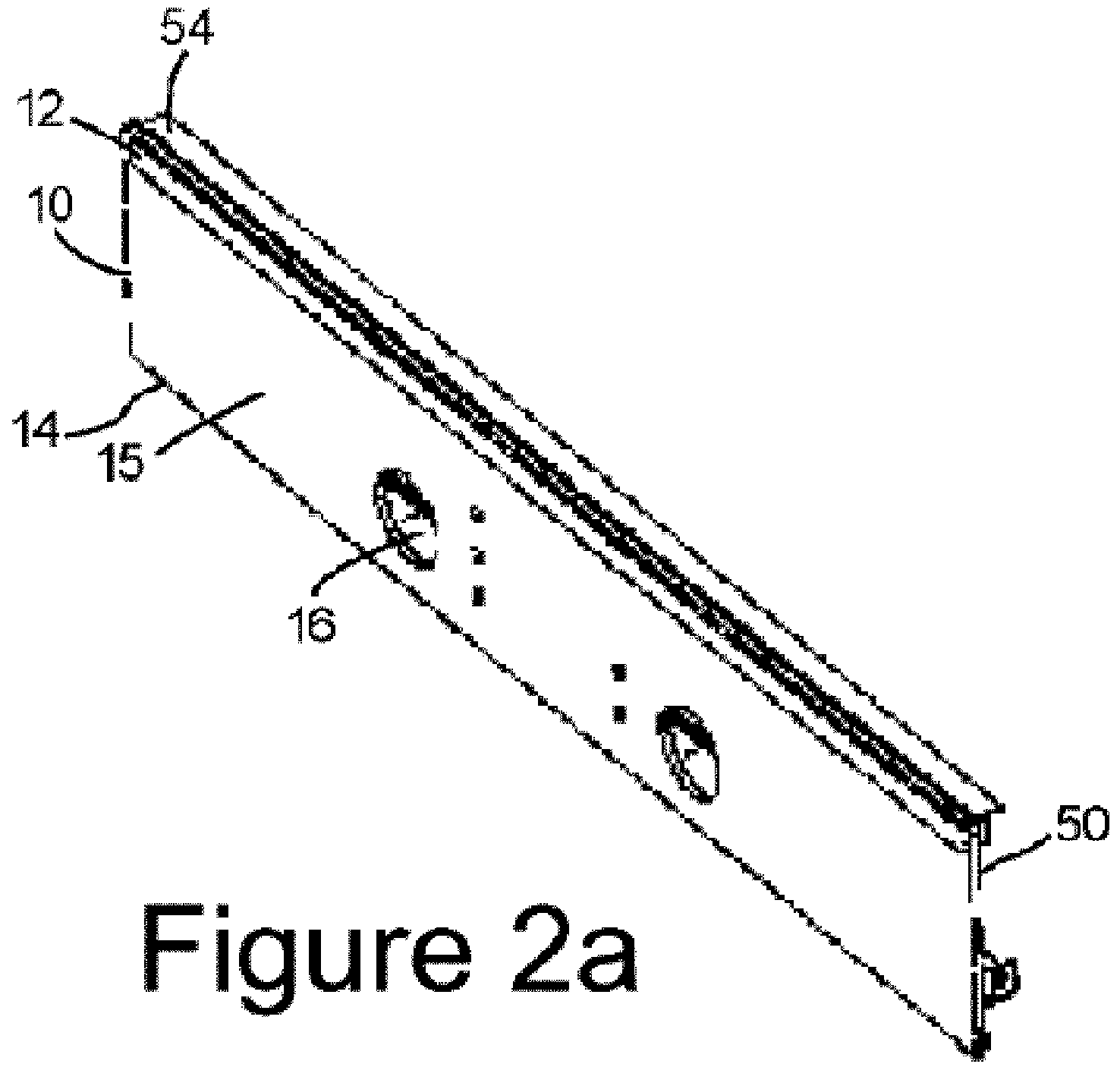
- FIG. 2a and 2b a representative embodiment of the subject matter control panel (10) is illustrated.
- the control panel (10) has a rectangular form. At the position close to the upper edge of the control panel (10), a transparent section (12) from end to end is delimited.
- the transparent section (12) is a transparent glass form permitting light passage through the control panel (10) between a rear surface (11) and a front surface provided on the opposite section with respect to said rear surface (11).
- the regions outside the transparent section (12) define opaque section (15) which does not transmit light through.
- the opaque section (15) is in black color.
- a reflective strip (20) is aligned so as to correspond to the transparent section (12).
- the reflective strip (20) is a thin and long strip having a light reflecting film on the front face thereof.
- An adhesion element (30) is positioned at the rear section of the reflective strip (20).
- Said adhesion element (30) is a double-sided band which is wider than the reflective strip (20).
- the adhesion element (30) is adhered to the rear face of the reflective strip (20) from one face thereof.
- the adhesion element (30) is adhered to a rear panel (50), which is a wide metal plate, from one face thereof.
- the rear panel (40) is dimensioned so as to cover the control panel (10) from the rear section.
- a flat support panel (40) is positioned between the control panel (10) and the rear panel (40).
- the upper edge of the support panel (40) is spaced apart from the upper edge of the control panel (10).
- a support section (52), defined at the upper edge of the rear panel (50) and where the reflective strip (20) is held from the rear side aligns the reflective strip (20) to the transparent section (12) provided at the control panel (10).
- the control panel (10) forms a sandwich structure together with the support panel (40) and the rear panel (50).
- a connection flap (54) reaching the control panel (10), is extended on the rear panel (50).
- reflective strip (20) is used in order to define a region which reflects the light coming from outside and which attracts visual attention to the control panel (10).
- the reflective strip (20) is fixed to the rear surface (11) of the control panel (10) where exhaust opening (5) extends along the lower edge thereof. By means of the sandwich structure of the control panel (10), the discharge vapor blown through the exhaust opening (5) towards outside of the body (1) cannot reach the reflective strip (20).
- the support panel (40) is adjacent to the reflective strip (20) from the lower section.
- the support panel (40) which remains in between, forms housing where the reflective strip (20) is seated from the upper section at the alignment of the support section (52).
- the reflective strip (20) fixed in the housing, receives outer ambience light arriving at the transparent section (12) and the control panel (10) from the front section and it partially reflects the outer ambience light.
- the reflective strip (20) is made of steel material which is brushed so as to decrease the amount of light reflection. In alternative embodiments, the reflective strip (20) can be configured so as to have chrome, aluminum or similar metallic surface.
Landscapes
- Engineering & Computer Science (AREA)
- Chemical & Material Sciences (AREA)
- Combustion & Propulsion (AREA)
- Mechanical Engineering (AREA)
- General Engineering & Computer Science (AREA)
- Electric Ovens (AREA)
- Electric Stoves And Ranges (AREA)
Abstract
Description
- The present invention relates to control panels of domestic ovens where cooking is realized.
- In the oven body, there is a cooking chamber, a door closing the cooking chamber in an openable manner, and a control panel positioned at the upper section of the door. On the control panel, pluralities of setting elements are placed in order for the user to realize the cooking setting. The setting elements comprise a button, a rotary button which provides transmitting of the setting commands physically, or a screen for informing the user or for providing the user to make information entry. Since glass and partially light transmittance based materials can be easily cleaned, the outermost layer of the control panel is made of glass or a partially light transmittance material.
- In order to draw the attention of the user to the control panel visually, strips with reflective surface are adhered onto the control panel. In the control panels which is made of partially light transmittance material, the strip, having a reflective layer on the outer section, is fixed on the glass by means of an adhesive. However, in domestic ovens where vapor output occurs under the control panel, the oily vapor rises through the outlet, and it adheres onto the reflective layer provided on the control panel. In order to clean the oily layer, oil solvent chemicals are applied onto the control panel. The oil solvent chemicals and the abrasive cleaning apparatus used for cleaning may lead to abrasion of the reflective surface in time.
- The object of the present invention is to facilitate cleaning of partially light transmittance material and especially glass based control panel provided in domestic ovens.
- In order to realize the abovementioned object, the present invention is an oven comprising a cooking chamber covered by an openable door, a control panel provided above the upper section of the door and made of a partially light transmittance material. In a preferred embodiment of the present invention, there is a transparent section and by a reflective strip positioned at the transparent section on a rear surface of the control panel. When the oily vapor occurring as a result of cooking is discharged through the exhaust opening, the oily vapor may smear to the control panel; however, the oily vapor cannot directly access the reflective strip. In this case, when the transparent section of the control panel is cleaned from outside, the light reflection efficiency of the reflective strip provided on the rear surface is easily increased. In a probable embodiment, the reflective strip may be in the form of a plate, and in an alternative embodiment, it may be a layer applied to the transparent section so as to cover from the rear wall.
- In a preferred embodiment of the present invention, the transparent section and the corresponding reflective strip are extended transversely on the control panel. Thus, the most efficient visual access area is provided since it occupies a small area along the control panel. In a probable embodiment, the reflective strip and the corresponding transparent section have a sectioned form. By means of this, a different optical effect can be obtained. In a probable embodiment, in order to draw visual attention to the section where clock and other control elements are provided on the control panel, a piece may extend, and in other sections, reflective strip may extend as the continuation of said piece.
- In a preferred embodiment of the present invention, there is an adhesion element is fixed to the reflective strip. The adhesion element facilitates the assembly of the reflective strip to the transparent section. In a probable embodiment, the reflective strip is fixed by means of a housing formed so as to be close to the transparent section on the rear surface of the control panel.
- In a preferred embodiment of the present invention, the control panel comprises a support panel and the reflective strip is located in sandwich form between the support panel and the control panel. The support panel applies pressure from the rear surface of the control panel and pushes the reflective strip to the transparent section. By means of this, the compression pressure is equally distributed to the reflective strip along the transparent section. The reflective strip is protected from effects like hot air, humidity after assembly by means of the support panel covering the rear section thereof.
- In a preferred embodiment of the present invention, the adhesion element is a double-sided adhesive band which adheres to the reflective strip from one side and which adheres to the support panel from the other side. In this case, the double-sided band adhered to the reflective strip from the front section can be fixed to a support element from the rear section thereof, for instance, it can be fixed to the support panel. In a probable embodiment, the adhesion element has an adhesion band structure which is wider than the reflective strip. The band, whose adhesive section is for instance made of acrylic foam, overflows from the periphery of the reflective strip, and fixes the reflective strip to the rear surface of the control panel from the peripheral adjacent edges of the transparent section.
- In a preferred embodiment of the present invention, there is a rear panel is fixed to the control panel so that the support panel is confined between the control panel and the rear panel. The rear panel provides the support panel to apply pressure to the reflective element. In a probable embodiment, the rear panel bears connection elements extending to the control panel in order to keep the sandwich structure together.
- In a preferred embodiment of the present invention, the control panel, the support panel and the rear panel are in the form of parallel and abutted plates. By means of this, a compact structure is obtained which is in the form of abutted plates.
-
Figure 1 is the frontal schematic view of an oven comprising a representative embodiment of the subject matter control panel. -
Figure 2a is the perspective assembly view of a representative embodiment of the subject matter control panel. -
Figure 2b is the exploded view of the embodiment illustrated inFigure 2a . - In this detailed description, the subject matter improvement is explained with references to examples without forming any restrictive effect only in order to make the subject more understandable.
- In
Figure 1 , the frontal view of a domestic oven is given. The oven body (1) comprises a cooking chamber (7) wherein the heating equipment is provided and wherein the items to be cooked are placed. The cooking chamber (7) is covered by means of a door (4) which can be opened by drawing. Flanges (3) are provided at the two mutual sides of the door (4). At the front upper section of the body (1), there is a control panel (10) which is in partially light transmittance form. Control elements (2) are arranged on the control panel (10). The control elements (2) comprise a digital display and buttons (6) provided around said display. In order for the buttons (6) to pass through the control panel (10), the partially light transmittance material is cut in the form of a button opening (16) which has a form suitable for the button (6) passage. On the body (1), an exhaust opening (5) is provided between the upper section of the door (4) and the control panel (10). The exhaust opening (5) extends from end to end transversely under the control panel (10). - In
Figure 2a and 2b , a representative embodiment of the subject matter control panel (10) is illustrated. The control panel (10) has a rectangular form. At the position close to the upper edge of the control panel (10), a transparent section (12) from end to end is delimited. The transparent section (12) is a transparent glass form permitting light passage through the control panel (10) between a rear surface (11) and a front surface provided on the opposite section with respect to said rear surface (11). On the control panel (10), the regions outside the transparent section (12) define opaque section (15) which does not transmit light through. The opaque section (15) is in black color. - On the back surface (11) of the control panel (10), a reflective strip (20) is aligned so as to correspond to the transparent section (12). The reflective strip (20) is a thin and long strip having a light reflecting film on the front face thereof. An adhesion element (30) is positioned at the rear section of the reflective strip (20). Said adhesion element (30) is a double-sided band which is wider than the reflective strip (20). The adhesion element (30) is adhered to the rear face of the reflective strip (20) from one face thereof. The adhesion element (30) is adhered to a rear panel (50), which is a wide metal plate, from one face thereof. The rear panel (40) is dimensioned so as to cover the control panel (10) from the rear section. A flat support panel (40) is positioned between the control panel (10) and the rear panel (40). The upper edge of the support panel (40) is spaced apart from the upper edge of the control panel (10). Thus, a support section (52), defined at the upper edge of the rear panel (50) and where the reflective strip (20) is held from the rear side, aligns the reflective strip (20) to the transparent section (12) provided at the control panel (10). The control panel (10) forms a sandwich structure together with the support panel (40) and the rear panel (50). In order to provide this, a connection flap (54), reaching the control panel (10), is extended on the rear panel (50).
- At the control panel (10) provided on the oven body (1), reflective strip (20) is used in order to define a region which reflects the light coming from outside and which attracts visual attention to the control panel (10). The reflective strip (20) is fixed to the rear surface (11) of the control panel (10) where exhaust opening (5) extends along the lower edge thereof. By means of the sandwich structure of the control panel (10), the discharge vapor blown through the exhaust opening (5) towards outside of the body (1) cannot reach the reflective strip (20). The support panel (40) is adjacent to the reflective strip (20) from the lower section. When the rear panel (50) and the control panel (10) overlap onto each other along the lateral surfaces thereof, the support panel (40), which remains in between, forms housing where the reflective strip (20) is seated from the upper section at the alignment of the support section (52). The reflective strip (20), fixed in the housing, receives outer ambiance light arriving at the transparent section (12) and the control panel (10) from the front section and it partially reflects the outer ambiance light. The reflective strip (20) is made of steel material which is brushed so as to decrease the amount of light reflection. In alternative embodiments, the reflective strip (20) can be configured so as to have chrome, aluminum or similar metallic surface.
-
- 1
- Body
- 2
- Control element
- 3
- Flange
- 4
- Door
- 5
- Exhaust opening
- 6
- Button
- 7
- Cooking chamber
- 10
- Control panel
- 11
- Rear surface
- 12
- Transparent section
- 14
- Lower edge
- 15
- Opaque section
- 16
- Button opening
- 20
- Reflective strip
- 30
- Adhesion element
- 40
- Support panel
- 50
- Rear panel
- 52
- Support section
- 54
- Connection flap
Claims (7)
- An oven comprising a cooking chamber (7) covered by an openable door (4), a control panel (10) provided above the upper section of the door (4) and made of a partially light transmittance material characterized by the control panel (10) comprising a transparent section (12) and by a reflective strip (20) positioned at the transparent section (12) on a rear surface (11) of the control panel (10).
- An oven according to Claim 1, wherein the transparent section (12) and the corresponding reflective strip (20) are extended transversely on the control panel (10).
- An oven according to any one of the preceding claims, wherein an adhesion element (30) is fixed to the reflective strip (20).
- An oven according to any one of the preceding claims, wherein the control panel (10) comprises a support panel (40) and the reflective strip (20) is located in sandwich form between the support panel (40) and the control panel (10).
- An oven according to Claim 4, wherein the adhesion element (30) is a double-sided adhesive band which adheres to the reflective strip (20) from one side and which adheres to the support panel (40) from the other side.
- An oven according to Claim 5, wherein a rear panel (50) is fixed to the control panel (10) so that the support panel (40) is confined between the control panel (10) and the rear panel (50).
- An oven according to Claim 6, wherein the control panel (10), the support panel (40) and the rear panel (50) are in the form of parallel and abutted plates.
Applications Claiming Priority (1)
| Application Number | Priority Date | Filing Date | Title |
|---|---|---|---|
| TR201516334 | 2015-12-18 |
Publications (2)
| Publication Number | Publication Date |
|---|---|
| EP3182018A1 true EP3182018A1 (en) | 2017-06-21 |
| EP3182018B1 EP3182018B1 (en) | 2019-04-17 |
Family
ID=57406149
Family Applications (1)
| Application Number | Title | Priority Date | Filing Date |
|---|---|---|---|
| EP16200839.5A Active EP3182018B1 (en) | 2015-12-18 | 2016-11-28 | An oven having a control panel |
Country Status (2)
| Country | Link |
|---|---|
| EP (1) | EP3182018B1 (en) |
| RU (1) | RU2016149067A (en) |
Citations (2)
| Publication number | Priority date | Publication date | Assignee | Title |
|---|---|---|---|---|
| EP0826489A1 (en) * | 1996-08-22 | 1998-03-04 | Vtf Industries, S.A.R.L. | Method for making a decorated facade protection, in particular for electrical household appliance |
| EP1160513A2 (en) * | 2000-05-31 | 2001-12-05 | BSH Bosch und Siemens Hausgeräte GmbH | Domestic appliance with a front control panel |
-
2016
- 2016-11-28 EP EP16200839.5A patent/EP3182018B1/en active Active
- 2016-12-14 RU RU2016149067A patent/RU2016149067A/en not_active Application Discontinuation
Patent Citations (2)
| Publication number | Priority date | Publication date | Assignee | Title |
|---|---|---|---|---|
| EP0826489A1 (en) * | 1996-08-22 | 1998-03-04 | Vtf Industries, S.A.R.L. | Method for making a decorated facade protection, in particular for electrical household appliance |
| EP1160513A2 (en) * | 2000-05-31 | 2001-12-05 | BSH Bosch und Siemens Hausgeräte GmbH | Domestic appliance with a front control panel |
Also Published As
| Publication number | Publication date |
|---|---|
| EP3182018B1 (en) | 2019-04-17 |
| RU2016149067A (en) | 2018-06-14 |
Similar Documents
| Publication | Publication Date | Title |
|---|---|---|
| US20180375974A1 (en) | Cover glass for mobile device | |
| EP1862741A2 (en) | Door assembly for a cooking apparatus | |
| US20090255524A1 (en) | Built-in oven | |
| US4207863A (en) | Door for pyrolytic range | |
| JP2009534563A5 (en) | ||
| US20090078244A1 (en) | Metal panel, manufacturing method thereof and cooking device using the metal panel | |
| RU2007107920A (en) | DOOR INTENDED FOR CLOSING THE ACCESS INSIDE THE AIRCRAFT | |
| US11029033B2 (en) | Cooker | |
| EP3159610A1 (en) | Oven for cooking food | |
| EP3182018B1 (en) | An oven having a control panel | |
| TWI698842B (en) | Building material glass plate with display device and building material glass structure | |
| US11765796B2 (en) | Microwave cooking appliance with leak detection | |
| TWI231858B (en) | Drop-in type stove | |
| GB2331357A (en) | Oven liners | |
| US20070023029A1 (en) | Door assembly for a cooking appliance | |
| CA2155057A1 (en) | Flat high temperature membrane switch display window | |
| US3228388A (en) | Oven window-door | |
| EP2541151A1 (en) | High-frequency cooking device | |
| EP3106067B1 (en) | Insulating glazing unit with projection and input means | |
| US3384072A (en) | Oven door | |
| US4292488A (en) | Microwave oven door having a conformable screen | |
| JP4407954B2 (en) | Kitchen stand with indicator | |
| US20030029560A1 (en) | Method of eliminating and a laminate which eliminates aesthetically unacceptable hues visible through light-colored translucent overlays | |
| CN212160644U (en) | Cover plate and black edge structure | |
| EP1475507A2 (en) | A door |
Legal Events
| Date | Code | Title | Description |
|---|---|---|---|
| PUAI | Public reference made under article 153(3) epc to a published international application that has entered the european phase |
Free format text: ORIGINAL CODE: 0009012 |
|
| STAA | Information on the status of an ep patent application or granted ep patent |
Free format text: STATUS: THE APPLICATION HAS BEEN PUBLISHED |
|
| AK | Designated contracting states |
Kind code of ref document: A1 Designated state(s): AL AT BE BG CH CY CZ DE DK EE ES FI FR GB GR HR HU IE IS IT LI LT LU LV MC MK MT NL NO PL PT RO RS SE SI SK SM TR |
|
| AX | Request for extension of the european patent |
Extension state: BA ME |
|
| STAA | Information on the status of an ep patent application or granted ep patent |
Free format text: STATUS: REQUEST FOR EXAMINATION WAS MADE |
|
| 17P | Request for examination filed |
Effective date: 20171221 |
|
| RBV | Designated contracting states (corrected) |
Designated state(s): AL AT BE BG CH CY CZ DE DK EE ES FI FR GB GR HR HU IE IS IT LI LT LU LV MC MK MT NL NO PL PT RO RS SE SI SK SM TR |
|
| GRAP | Despatch of communication of intention to grant a patent |
Free format text: ORIGINAL CODE: EPIDOSNIGR1 |
|
| STAA | Information on the status of an ep patent application or granted ep patent |
Free format text: STATUS: GRANT OF PATENT IS INTENDED |
|
| INTG | Intention to grant announced |
Effective date: 20181116 |
|
| GRAS | Grant fee paid |
Free format text: ORIGINAL CODE: EPIDOSNIGR3 |
|
| GRAA | (expected) grant |
Free format text: ORIGINAL CODE: 0009210 |
|
| STAA | Information on the status of an ep patent application or granted ep patent |
Free format text: STATUS: THE PATENT HAS BEEN GRANTED |
|
| AK | Designated contracting states |
Kind code of ref document: B1 Designated state(s): AL AT BE BG CH CY CZ DE DK EE ES FI FR GB GR HR HU IE IS IT LI LT LU LV MC MK MT NL NO PL PT RO RS SE SI SK SM TR |
|
| REG | Reference to a national code |
Ref country code: GB Ref legal event code: FG4D |
|
| REG | Reference to a national code |
Ref country code: CH Ref legal event code: EP |
|
| REG | Reference to a national code |
Ref country code: DE Ref legal event code: R096 Ref document number: 602016012506 Country of ref document: DE |
|
| REG | Reference to a national code |
Ref country code: AT Ref legal event code: REF Ref document number: 1121954 Country of ref document: AT Kind code of ref document: T Effective date: 20190515 Ref country code: IE Ref legal event code: FG4D |
|
| REG | Reference to a national code |
Ref country code: NL Ref legal event code: MP Effective date: 20190417 |
|
| REG | Reference to a national code |
Ref country code: LT Ref legal event code: MG4D |
|
| PG25 | Lapsed in a contracting state [announced via postgrant information from national office to epo] |
Ref country code: NL Free format text: LAPSE BECAUSE OF FAILURE TO SUBMIT A TRANSLATION OF THE DESCRIPTION OR TO PAY THE FEE WITHIN THE PRESCRIBED TIME-LIMIT Effective date: 20190417 |
|
| PG25 | Lapsed in a contracting state [announced via postgrant information from national office to epo] |
Ref country code: ES Free format text: LAPSE BECAUSE OF FAILURE TO SUBMIT A TRANSLATION OF THE DESCRIPTION OR TO PAY THE FEE WITHIN THE PRESCRIBED TIME-LIMIT Effective date: 20190417 Ref country code: LT Free format text: LAPSE BECAUSE OF FAILURE TO SUBMIT A TRANSLATION OF THE DESCRIPTION OR TO PAY THE FEE WITHIN THE PRESCRIBED TIME-LIMIT Effective date: 20190417 Ref country code: SE Free format text: LAPSE BECAUSE OF FAILURE TO SUBMIT A TRANSLATION OF THE DESCRIPTION OR TO PAY THE FEE WITHIN THE PRESCRIBED TIME-LIMIT Effective date: 20190417 Ref country code: HR Free format text: LAPSE BECAUSE OF FAILURE TO SUBMIT A TRANSLATION OF THE DESCRIPTION OR TO PAY THE FEE WITHIN THE PRESCRIBED TIME-LIMIT Effective date: 20190417 Ref country code: PT Free format text: LAPSE BECAUSE OF FAILURE TO SUBMIT A TRANSLATION OF THE DESCRIPTION OR TO PAY THE FEE WITHIN THE PRESCRIBED TIME-LIMIT Effective date: 20190817 Ref country code: NO Free format text: LAPSE BECAUSE OF FAILURE TO SUBMIT A TRANSLATION OF THE DESCRIPTION OR TO PAY THE FEE WITHIN THE PRESCRIBED TIME-LIMIT Effective date: 20190717 Ref country code: FI Free format text: LAPSE BECAUSE OF FAILURE TO SUBMIT A TRANSLATION OF THE DESCRIPTION OR TO PAY THE FEE WITHIN THE PRESCRIBED TIME-LIMIT Effective date: 20190417 Ref country code: AL Free format text: LAPSE BECAUSE OF FAILURE TO SUBMIT A TRANSLATION OF THE DESCRIPTION OR TO PAY THE FEE WITHIN THE PRESCRIBED TIME-LIMIT Effective date: 20190417 |
|
| PG25 | Lapsed in a contracting state [announced via postgrant information from national office to epo] |
Ref country code: PL Free format text: LAPSE BECAUSE OF FAILURE TO SUBMIT A TRANSLATION OF THE DESCRIPTION OR TO PAY THE FEE WITHIN THE PRESCRIBED TIME-LIMIT Effective date: 20190417 Ref country code: LV Free format text: LAPSE BECAUSE OF FAILURE TO SUBMIT A TRANSLATION OF THE DESCRIPTION OR TO PAY THE FEE WITHIN THE PRESCRIBED TIME-LIMIT Effective date: 20190417 Ref country code: GR Free format text: LAPSE BECAUSE OF FAILURE TO SUBMIT A TRANSLATION OF THE DESCRIPTION OR TO PAY THE FEE WITHIN THE PRESCRIBED TIME-LIMIT Effective date: 20190718 Ref country code: BG Free format text: LAPSE BECAUSE OF FAILURE TO SUBMIT A TRANSLATION OF THE DESCRIPTION OR TO PAY THE FEE WITHIN THE PRESCRIBED TIME-LIMIT Effective date: 20190717 Ref country code: RS Free format text: LAPSE BECAUSE OF FAILURE TO SUBMIT A TRANSLATION OF THE DESCRIPTION OR TO PAY THE FEE WITHIN THE PRESCRIBED TIME-LIMIT Effective date: 20190417 |
|
| REG | Reference to a national code |
Ref country code: AT Ref legal event code: MK05 Ref document number: 1121954 Country of ref document: AT Kind code of ref document: T Effective date: 20190417 |
|
| PG25 | Lapsed in a contracting state [announced via postgrant information from national office to epo] |
Ref country code: IS Free format text: LAPSE BECAUSE OF FAILURE TO SUBMIT A TRANSLATION OF THE DESCRIPTION OR TO PAY THE FEE WITHIN THE PRESCRIBED TIME-LIMIT Effective date: 20190817 |
|
| REG | Reference to a national code |
Ref country code: DE Ref legal event code: R097 Ref document number: 602016012506 Country of ref document: DE |
|
| PG25 | Lapsed in a contracting state [announced via postgrant information from national office to epo] |
Ref country code: CZ Free format text: LAPSE BECAUSE OF FAILURE TO SUBMIT A TRANSLATION OF THE DESCRIPTION OR TO PAY THE FEE WITHIN THE PRESCRIBED TIME-LIMIT Effective date: 20190417 Ref country code: RO Free format text: LAPSE BECAUSE OF FAILURE TO SUBMIT A TRANSLATION OF THE DESCRIPTION OR TO PAY THE FEE WITHIN THE PRESCRIBED TIME-LIMIT Effective date: 20190417 Ref country code: SK Free format text: LAPSE BECAUSE OF FAILURE TO SUBMIT A TRANSLATION OF THE DESCRIPTION OR TO PAY THE FEE WITHIN THE PRESCRIBED TIME-LIMIT Effective date: 20190417 Ref country code: EE Free format text: LAPSE BECAUSE OF FAILURE TO SUBMIT A TRANSLATION OF THE DESCRIPTION OR TO PAY THE FEE WITHIN THE PRESCRIBED TIME-LIMIT Effective date: 20190417 Ref country code: DK Free format text: LAPSE BECAUSE OF FAILURE TO SUBMIT A TRANSLATION OF THE DESCRIPTION OR TO PAY THE FEE WITHIN THE PRESCRIBED TIME-LIMIT Effective date: 20190417 Ref country code: AT Free format text: LAPSE BECAUSE OF FAILURE TO SUBMIT A TRANSLATION OF THE DESCRIPTION OR TO PAY THE FEE WITHIN THE PRESCRIBED TIME-LIMIT Effective date: 20190417 |
|
| PLBE | No opposition filed within time limit |
Free format text: ORIGINAL CODE: 0009261 |
|
| STAA | Information on the status of an ep patent application or granted ep patent |
Free format text: STATUS: NO OPPOSITION FILED WITHIN TIME LIMIT |
|
| PG25 | Lapsed in a contracting state [announced via postgrant information from national office to epo] |
Ref country code: SM Free format text: LAPSE BECAUSE OF FAILURE TO SUBMIT A TRANSLATION OF THE DESCRIPTION OR TO PAY THE FEE WITHIN THE PRESCRIBED TIME-LIMIT Effective date: 20190417 |
|
| 26N | No opposition filed |
Effective date: 20200120 |
|
| PG25 | Lapsed in a contracting state [announced via postgrant information from national office to epo] |
Ref country code: SI Free format text: LAPSE BECAUSE OF FAILURE TO SUBMIT A TRANSLATION OF THE DESCRIPTION OR TO PAY THE FEE WITHIN THE PRESCRIBED TIME-LIMIT Effective date: 20190417 |
|
| REG | Reference to a national code |
Ref country code: DE Ref legal event code: R119 Ref document number: 602016012506 Country of ref document: DE |
|
| REG | Reference to a national code |
Ref country code: CH Ref legal event code: PL |
|
| PG25 | Lapsed in a contracting state [announced via postgrant information from national office to epo] |
Ref country code: MC Free format text: LAPSE BECAUSE OF FAILURE TO SUBMIT A TRANSLATION OF THE DESCRIPTION OR TO PAY THE FEE WITHIN THE PRESCRIBED TIME-LIMIT Effective date: 20190417 Ref country code: CH Free format text: LAPSE BECAUSE OF NON-PAYMENT OF DUE FEES Effective date: 20191130 Ref country code: LU Free format text: LAPSE BECAUSE OF NON-PAYMENT OF DUE FEES Effective date: 20191128 Ref country code: LI Free format text: LAPSE BECAUSE OF NON-PAYMENT OF DUE FEES Effective date: 20191130 |
|
| REG | Reference to a national code |
Ref country code: BE Ref legal event code: MM Effective date: 20191130 |
|
| PG25 | Lapsed in a contracting state [announced via postgrant information from national office to epo] |
Ref country code: DE Free format text: LAPSE BECAUSE OF NON-PAYMENT OF DUE FEES Effective date: 20200603 Ref country code: IE Free format text: LAPSE BECAUSE OF NON-PAYMENT OF DUE FEES Effective date: 20191128 Ref country code: FR Free format text: LAPSE BECAUSE OF NON-PAYMENT OF DUE FEES Effective date: 20191130 |
|
| PG25 | Lapsed in a contracting state [announced via postgrant information from national office to epo] |
Ref country code: BE Free format text: LAPSE BECAUSE OF NON-PAYMENT OF DUE FEES Effective date: 20191130 |
|
| PG25 | Lapsed in a contracting state [announced via postgrant information from national office to epo] |
Ref country code: CY Free format text: LAPSE BECAUSE OF FAILURE TO SUBMIT A TRANSLATION OF THE DESCRIPTION OR TO PAY THE FEE WITHIN THE PRESCRIBED TIME-LIMIT Effective date: 20190417 |
|
| GBPC | Gb: european patent ceased through non-payment of renewal fee |
Effective date: 20201128 |
|
| PG25 | Lapsed in a contracting state [announced via postgrant information from national office to epo] |
Ref country code: MT Free format text: LAPSE BECAUSE OF FAILURE TO SUBMIT A TRANSLATION OF THE DESCRIPTION OR TO PAY THE FEE WITHIN THE PRESCRIBED TIME-LIMIT Effective date: 20190417 Ref country code: HU Free format text: LAPSE BECAUSE OF FAILURE TO SUBMIT A TRANSLATION OF THE DESCRIPTION OR TO PAY THE FEE WITHIN THE PRESCRIBED TIME-LIMIT; INVALID AB INITIO Effective date: 20161128 |
|
| PG25 | Lapsed in a contracting state [announced via postgrant information from national office to epo] |
Ref country code: GB Free format text: LAPSE BECAUSE OF NON-PAYMENT OF DUE FEES Effective date: 20201128 |
|
| PG25 | Lapsed in a contracting state [announced via postgrant information from national office to epo] |
Ref country code: MK Free format text: LAPSE BECAUSE OF FAILURE TO SUBMIT A TRANSLATION OF THE DESCRIPTION OR TO PAY THE FEE WITHIN THE PRESCRIBED TIME-LIMIT Effective date: 20190417 |
|
| PGFP | Annual fee paid to national office [announced via postgrant information from national office to epo] |
Ref country code: IT Payment date: 20251128 Year of fee payment: 10 |
|
| PGFP | Annual fee paid to national office [announced via postgrant information from national office to epo] |
Ref country code: TR Payment date: 20251124 Year of fee payment: 10 |