EP3181935B1 - Frein a disque electromecanique comportant un etrier portant deux plaquettes basculantes - Google Patents
Frein a disque electromecanique comportant un etrier portant deux plaquettes basculantes Download PDFInfo
- Publication number
- EP3181935B1 EP3181935B1 EP16204476.2A EP16204476A EP3181935B1 EP 3181935 B1 EP3181935 B1 EP 3181935B1 EP 16204476 A EP16204476 A EP 16204476A EP 3181935 B1 EP3181935 B1 EP 3181935B1
- Authority
- EP
- European Patent Office
- Prior art keywords
- mechanical axis
- caliper
- pad
- pads
- stop
- Prior art date
- Legal status (The legal status is an assumption and is not a legal conclusion. Google has not performed a legal analysis and makes no representation as to the accuracy of the status listed.)
- Active
Links
Images


Classifications
-
- F—MECHANICAL ENGINEERING; LIGHTING; HEATING; WEAPONS; BLASTING
- F16—ENGINEERING ELEMENTS AND UNITS; GENERAL MEASURES FOR PRODUCING AND MAINTAINING EFFECTIVE FUNCTIONING OF MACHINES OR INSTALLATIONS; THERMAL INSULATION IN GENERAL
- F16D—COUPLINGS FOR TRANSMITTING ROTATION; CLUTCHES; BRAKES
- F16D55/00—Brakes with substantially-radial braking surfaces pressed together in axial direction, e.g. disc brakes
- F16D55/02—Brakes with substantially-radial braking surfaces pressed together in axial direction, e.g. disc brakes with axially-movable discs or pads pressed against axially-located rotating members
- F16D55/22—Brakes with substantially-radial braking surfaces pressed together in axial direction, e.g. disc brakes with axially-movable discs or pads pressed against axially-located rotating members by clamping an axially-located rotating disc between movable braking members, e.g. movable brake discs or brake pads
- F16D55/224—Brakes with substantially-radial braking surfaces pressed together in axial direction, e.g. disc brakes with axially-movable discs or pads pressed against axially-located rotating members by clamping an axially-located rotating disc between movable braking members, e.g. movable brake discs or brake pads with a common actuating member for the braking members
- F16D55/225—Brakes with substantially-radial braking surfaces pressed together in axial direction, e.g. disc brakes with axially-movable discs or pads pressed against axially-located rotating members by clamping an axially-located rotating disc between movable braking members, e.g. movable brake discs or brake pads with a common actuating member for the braking members the braking members being brake pads
- F16D55/2255—Brakes with substantially-radial braking surfaces pressed together in axial direction, e.g. disc brakes with axially-movable discs or pads pressed against axially-located rotating members by clamping an axially-located rotating disc between movable braking members, e.g. movable brake discs or brake pads with a common actuating member for the braking members the braking members being brake pads in which the common actuating member is pivoted
-
- F—MECHANICAL ENGINEERING; LIGHTING; HEATING; WEAPONS; BLASTING
- F16—ENGINEERING ELEMENTS AND UNITS; GENERAL MEASURES FOR PRODUCING AND MAINTAINING EFFECTIVE FUNCTIONING OF MACHINES OR INSTALLATIONS; THERMAL INSULATION IN GENERAL
- F16D—COUPLINGS FOR TRANSMITTING ROTATION; CLUTCHES; BRAKES
- F16D55/00—Brakes with substantially-radial braking surfaces pressed together in axial direction, e.g. disc brakes
- F16D55/02—Brakes with substantially-radial braking surfaces pressed together in axial direction, e.g. disc brakes with axially-movable discs or pads pressed against axially-located rotating members
- F16D55/22—Brakes with substantially-radial braking surfaces pressed together in axial direction, e.g. disc brakes with axially-movable discs or pads pressed against axially-located rotating members by clamping an axially-located rotating disc between movable braking members, e.g. movable brake discs or brake pads
- F16D55/224—Brakes with substantially-radial braking surfaces pressed together in axial direction, e.g. disc brakes with axially-movable discs or pads pressed against axially-located rotating members by clamping an axially-located rotating disc between movable braking members, e.g. movable brake discs or brake pads with a common actuating member for the braking members
- F16D55/2245—Brakes with substantially-radial braking surfaces pressed together in axial direction, e.g. disc brakes with axially-movable discs or pads pressed against axially-located rotating members by clamping an axially-located rotating disc between movable braking members, e.g. movable brake discs or brake pads with a common actuating member for the braking members in which the common actuating member acts on two levers carrying the braking members, e.g. tong-type brakes
-
- F—MECHANICAL ENGINEERING; LIGHTING; HEATING; WEAPONS; BLASTING
- F16—ENGINEERING ELEMENTS AND UNITS; GENERAL MEASURES FOR PRODUCING AND MAINTAINING EFFECTIVE FUNCTIONING OF MACHINES OR INSTALLATIONS; THERMAL INSULATION IN GENERAL
- F16D—COUPLINGS FOR TRANSMITTING ROTATION; CLUTCHES; BRAKES
- F16D2121/00—Type of actuator operation force
- F16D2121/18—Electric or magnetic
- F16D2121/24—Electric or magnetic using motors
-
- F—MECHANICAL ENGINEERING; LIGHTING; HEATING; WEAPONS; BLASTING
- F16—ENGINEERING ELEMENTS AND UNITS; GENERAL MEASURES FOR PRODUCING AND MAINTAINING EFFECTIVE FUNCTIONING OF MACHINES OR INSTALLATIONS; THERMAL INSULATION IN GENERAL
- F16D—COUPLINGS FOR TRANSMITTING ROTATION; CLUTCHES; BRAKES
- F16D2125/00—Components of actuators
- F16D2125/18—Mechanical mechanisms
- F16D2125/20—Mechanical mechanisms converting rotation to linear movement or vice versa
- F16D2125/34—Mechanical mechanisms converting rotation to linear movement or vice versa acting in the direction of the axis of rotation
- F16D2125/40—Screw-and-nut
Definitions
- the invention relates to a disc brake for a motor vehicle with a fixed caliper, of the electromechanical type, that is to say fitted with an electric motor driving mechanical actuators.
- the document GB813316 A discloses a motor vehicle disc brake with a fixed caliper.
- the invention relates to a motor vehicle disc brake comprising a brake disc fitted with a caliper overlapping this disc and carrying a pair of friction pads each facing one face of the disc.
- This caliper further comprises an electric motor with actuating means for pressing these pads against the brake disc or releasing them depending on whether the brake is activated or deactivated.
- the object of the invention is to provide a general architecture of a disc brake caliper which is significantly simpler than that of known calipers, so as to reduce the manufacturing cost and / or improve the level of reliability and robustness. appropriate.
- the invention relates to a brake caliper as defined in independent claims 1 and 2.
- stirrup and its mounting have a simplified general structure, since it is no longer necessary for the plates to be floating in translation in the stirrup, as is the case with known stirrups.
- This arrangement also makes it possible to separate the service brake functions from the parking brake functions.
- the invention also relates to a caliper as defined in the dependent claims, and to a disc brake comprising such a caliper.
- the brake caliper according to the invention which is identified by 1 in the figure 1 comprises a fixed yoke 3 overlapping a disc 2.
- This fixed yoke 3 has a first lateral portion 4 by which it is carried by a chassis element not shown, and a second lateral portion 6, located opposite the first portion 4.
- the fixed yoke overlaps the disc 2 so that this disc is interposed between its lateral portions 4 and 6.
- the disc 2 typically comprises a flat crown delimited by an external edge and by a circular and concentric internal edge with an axis of revolution AX, this crown being carried by a hub not visible in the figures.
- the first portion 4 carries a first brake pad 7 and the second portion 6 carries a second pad 8, located opposite one another, these pads being tiltable, to be pressed against the disc when the brake is activated, and to be released when the brake is deactivated.
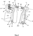
- the first and second plates 7 and 8 are symmetrical to each other with respect to a median plane of the disk 2, the general structure of the second plate 8 appearing more clearly on the figure 2 .
- the second plate 8 which runs along the disc 2 has a relatively thick base 9 extending at one end 11 which is significantly thinner.
- the base 9 is located in the vicinity of the internal edge of the disc, while the end 11 extends beyond the external edge of this disc 2.
- This plate 8 is carried by its base 9 which is tiltably mounted on the rest of the fixed yoke so as to provide the free end 11 with sufficient mobility to allow it to be either moved closer and pressed against the disc, or slightly apart of this disc 2.
- This plate 8 comprises a support or shoe 12, advantageously metallic, comprising a flat main wall 13 having a face opposite the disc 2 and an opposite face which carries one or two ribs 14, 16.
- the face opposite the disc 2 is covered with a friction material to generate braking when it is pressed against the disc 2.
- the rib or ribs 14, 16 extend parallel to one another. other, from the base 9 to the end 11, perpendicular to the main wall and being spaced from one another.
- the rib or ribs each comprise a hole or bore 17 intended to be crossed by a stud or a mechanical axis carried by the first portion 4 of the fixed yoke and oriented along an axis AY2 of orthoradial orientation relative to the axis AX of the disc.
- the plate 8 is thus pivotally mounted around the axis AY2, which allows its free end 11 to be brought closer or apart from the disc 2, depending on whether the brake is activated or deactivated.
- the first plate 7 has a shape and a design which are symmetrical to those of the plate 8, with respect to a median plane of the disk 2. It also has a free end 21 projecting from the outer edge of the disk and a base 19 opposite base 9, the ribs of which have a bore 18, and by which it is pivotally mounted in portion 4 of the fixed yoke 3 to pivot around an axis AY1 parallel to the axis AY2.
- the fixed yoke also carries an electromechanical actuation assembly.
- This assembly comprises a motor 22 coupled to a reduction gear 23 to drive a main mechanical axis 24 arranged to press these plates 7, 8 by their free ends 21, 11 against the disc 2, or to release them substantially, depending on whether the brake is on or off.
- the main mechanical axis 24 that the motor 22 drives through the reduction gear 23 is located beyond the outer edge of the disc 2, and it extends in a direction AX 'normal to the plane of the disc 2.
- This axis main mechanical 24 which is movable in translation along its longitudinal axis AX ′ crosses the main wall of each plate 7, 8 at the ends 21, 11 of these plates protruding from the external edge of the disc.
- This mechanical axis 24 also passes through a central support 29, rigidly secured to the fixed stirrup body, located midway between the ends of plates 11 and 21, and which constitutes a bearing carrying this axis 24.
- This central support 29 constitutes a bearing carrying the mechanical axis 24.
- a first and a second return spring 31 and 32, both helical and carried by the mechanical axis 24, are interposed between the central support 29 and the first plate 7, and between this central support 29 and the second plate 8.
- the mechanical axis 24 carries an end pinion 26 as well as a first and a second clamping stop 27, 28 placed respectively against the external faces of the two plates 7, 8.
- the first plate 7 thus has its end 11 which is clamped between the stop 27 and the return spring 31 which are both carried by the mechanical axis 24.
- the second plate 8 has its end 21 clamped between the stop 28 and the return spring 32 which are also carried by the axis mechanical 24.
- the central support 29 thus constitutes both a bearing carrying the axis 24 and a central stop.
- the end pinion 26 is rigidly secured to the mechanical axis 24 which carries it, and this axis 24 is free to rotate around its longitudinal axis AX ', in addition to being mobile in translation along this axis.
- the first stop 27 is screwed onto a corresponding thread on this mechanical axis 24 and it is blocked in rotation by a pin or the like protruding from the plate 7, so that when the mechanical axis 24 rotates in a first direction of rotation, this stop advances along the mechanical axis towards the support 29 of the axis 24.
- the second stop 28 is screwed onto another corresponding thread of the mechanical axis 24 and it is blocked in rotation by a pin or other projecting from the plate 8. But the direction of winding of the thread of this second stop 28 and the corresponding thread of the mechanical axis are in opposite directions to the direction of the thread of the stop 27 and the corresponding thread of the mechanical axis 24.
- the first stop 27 moves towards the central support 29 while the second stop 28 also moves towards this central support, which brings the ends 11 and 21 closer together. one of the other to press the pads against the disc 2 to cause braking.
- the longitudinal mobility of the axis 24 makes it possible to balance the forces exerted by the two stops against the pads.
- the first or the second stop 27, 28 is screwed onto the mechanical axis 24, the other stop being rigidly secured to this axis, which further reduces the manufacturing cost of the assembly.
- the pinion 26 is screwed onto a thread on the axis 24 and the first stop 27 is free to slide and rotate along this axis 24, this axis 24 is locked in rotation around its longitudinal axis while while being movable in translation along this longitudinal axis AX, and the second stop 28 is rigidly secured to the axis 24.
- the longitudinal axis AX has two opposite flats to give it an oblong section, and in a complementary manner, the holes passing through the ends 11 and 21 of the plates as well as the central support 29 have corresponding oblong sections, which makes it possible to block this axis. 24 in rotation while leaving it free in translation.
- the pinion 26 and the first stop 27 advantageously rigidly secured to one another constitute a pusher driven in rotation about the axis 24 by means of the pinion 33 driven by the motor, to move forward or back along this axis when motor 22 is activated.
- the first stop 27 advances along the axis 24 while being pushed by the pinion 26 to approach the central support 29 and the second stop 28, so as to press the pads against the disc to cause braking.
- the translational mobility of the mechanical axis 24 makes it possible to balance the forces exerted on the two pads 7 and 8, in particular in order to compensate for asymmetrical wear of these pads.
- the mechanical axis 24 naturally moves towards the pad 8, that is to say to the right on the figure 2 , to balance the forces to which it is subjected, and thereby ensure that the pads are pressed with the same intensity.
- the pinion 26 is driven by an output pinion 33 of the reduction gear 23, this output pinion 33 being rigidly secured to a toothed wheel 34 in which an output pinion 36 of the motor 22 is meshed.
- the pinions 33 and 26 are pinions with straight teeth of sufficient length to allow the pinion 26 to move along the axis AX while continuing to be driven in rotation by the motor 22 via the reduction gear 23.
- the geared motor assembly 23, forming an actuator, and / or each thread of the mechanical axis 24 is irreversible to keep the tilting plates 7 and 8 pressed on the disc without electrical power to the motor 22 or, on the contrary, to maintain them in the discarded position of the disc in non-braking condition.
- plates 7 and 8 provide, on command, the service, emergency and parking brakes.
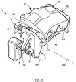
- the brake caliper comprises a fixed yoke 3 carrying on the one hand the tilting pads 7 and 8 as well as the electric geared motor 23 and on the other hand a floating caliper body 37 comprising hydraulic actuators for pressing another set of axially sliding pads.
- the tilting plates 7 and 8 provide emergency and parking braking, while the sliding plates pressed by floating caliper 37 with hydraulic control, provide service braking.
- the floating caliper body 37 is known per se, it comprises a base 38 in which are housed hydraulic actuators with piston not shown, this base being extended by a vault 39 ending in fingers 41, 42 and 43 located in screws opposite the base 38.
- this caliper body 37 encloses a sliding plate 44 located opposite its base 38, and another sliding plate 46 located opposite its fingers 41, 42, 43.
- These plates 44 and 46 are slidably mounted in corresponding grooves of the fixed yoke 3, being each located opposite a face of the disc, and they are pressed or released by the floating bracket.
- the caliper body 37 is mounted floating in the axial direction AX, so that when the pistons of its hydraulic actuators press the plate sliding 44 against the disc, it moves in the direction AX so that the opposite sliding plate, namely the plate 46, is also pressed against the opposite face of the disk.
- the fixed yoke 3 has a general shape corresponding to that of a usual fixed yoke, but one of the ends incorporates the lateral portions 4 and 6 visible on the figure 1 allowing to carry the tilting plates 7 and 8.
- this yoke 3 comprises a first base 48 straddling the brake disc while being oriented axially with respect thereto, and comprising a blind hole receiving a guide column for the floating caliper body 37.
- a second base 49 distant from the first in a tangential direction with respect to the disc also includes a blind hole receiving a second column for guiding the floating caliper body 37.
- These two bases 48 and 49 are connected to each other by two lateral arms identified by 51 and 52 which extend along the disc each opposite one of its faces.
- the second base 49 is extended by the lateral portions 4 and 6 spaced apart from each other on either side of the disc, and also by the central support 29 which extends the base 49 between the lateral portions 4 and 6 .
- the lateral portions 4 and 6 extend parallel to each other in a direction generally perpendicular to a plane passing through the columns of the floating body 37.
- the central support 39 extends in turn obliquely to the lateral portions 4 and 6, to go along the edge of the braking disc, not shown, having an orthoradial orientation relative to the axis AX.
Landscapes
- Engineering & Computer Science (AREA)
- General Engineering & Computer Science (AREA)
- Mechanical Engineering (AREA)
- Braking Arrangements (AREA)
Description
- L'invention se rapporte à un frein à disque de véhicule automobile à étrier fixe, de type électromécanique, c'est-à-dire équipé d'un moteur électrique entraînant des actionneurs mécaniques.
- Le document
GB813316 A - L'invention se rapporte à un frein à disque de véhicule automobile comportant un disque de freinage équipé d'un étrier chevauchant ce disque et portant une paire de plaquettes de friction chacune en regard d'une face du disque. Cet étrier comporte encore un moteur électrique avec des moyens d'actionnement pour presser ces plaquettes contre le disque de freinage ou les en relâcher selon que le frein est activé ou désactivé.
- Le but de l'invention est de proposer une architecture générale d'étrier de frein à disque qui soit significativement plus simple que celle des étriers connus, de manière à en réduire le coût de fabrication et/ou améliorer le niveau de fiabilité et de robustesse appropriés.
- A cet effet, l'invention a pour objet un étrier de frein tel que défini dans les revendications indépendantes 1 et 2.
- Avec cet agencement, l'étrier et son montage ont une structure générale simplifiée, puisqu'il n'est plus nécessaire que les plaquettes soient flottantes en translation dans l'étrier, comme c'est le cas avec les étriers connus. Cet agencement permet en outre de séparer les fonctions de frein de service des fonctions de frein de parc.
- L'invention concerne également un étrier tel que défini dans les revendications dépendantes, et un frein à disque comportant un tel étrier.
-
- La
figure 1 est une vue en coupe du frein selon l'invention conformément à un plan de coupe orthogonal ; - La
figure 2 est une vue en perspective montrant les plaquettes et leur ensemble d'actionnement du frein selon l'invention représentés seuls ; - La
figure 3 est une vue en perspective montrant dans son ensemble un étrier de frein selon l'invention ; - La
figure 4 est une vue de face montrant dans son ensemble un étrier de frein selon l'invention ; - La
figure 5 est une vue latérale montrant dans son ensemble un étrier de frein selon l'invention. - L'étrier de frein selon l'invention qui est repéré par 1 dans la
figure 1 comporte une chape fixe 3 chevauchant un disque 2. Cette chape fixe 3 comporte une première portion latérale 4 par laquelle il est porté par un élément de châssis non représenté, et une seconde portion latérale 6, située en vis-à-vis de la première portion 4. La chape fixe chevauche le disque 2 de sorte que ce disque est interposé entre ses portions latérales 4 et 6. - Le disque 2 comporte typiquement une couronne plane délimitée par un bord externe et par un bord interne circulaires et concentriques avec un axe de révolution AX, cette couronne étant portée par un moyeu non visible sur les figures.
- La première portion 4 porte une première plaquette de frein 7 et la seconde portion 6 porte une seconde plaquette 8, situées en vis-à-vis l'une de l'autre, ces plaquettes étant montées basculantes, pour être pressées contre le disque lorsque le frein est activé, et pour être relâchées lorsque le frein est désactivé.
- La première et la seconde plaquette 7 et 8 sont symétriques l'une de l'autre par rapport à un plan médian du disque 2, la structure générale de la seconde plaquette 8 apparaissant plus clairement sur la
figure 2 . - Comme visible sur cette
figure 2 , la seconde plaquette 8 qui longe le disque 2 comporte une base 9 relativement épaisse se prolongeant en une extrémité 11 significativement plus fine. La base 9 est située au voisinage du bord interne du disque, alors que l'extrémité 11 s'étend au-delà du bord extérieur de ce disque 2. - Cette plaquette 8 est portée par sa base 9 qui est montée basculante sur le reste de la chape fixe de façon à offrir à l'extrémité libre 11 une mobilité suffisante pour lui permettre d'être soit rapprochée et pressée contre le disque, soit légèrement écartée de ce disque 2.
- Cette plaquette 8 comporte un support ou sabot 12 avantageusement métallique, comprenant une paroi principale 13 plane ayant une face en vis-à-vis du disque 2 et une face opposée qui porte une ou deux nervures 14, 16.
- La face en vis-à-vis du disque 2 est couverte d'un matériau de friction pour générer le freinage lorsqu'elle est pressée contre le disque 2. La ou les nervures 14, 16 s'étendent parallèlement l'une à l'autre, depuis la base 9 jusqu'à l'extrémité 11, perpendiculairement à la paroi principale et en étant espacées l'une de l'autre.
- Au niveau de la base 9 de la plaquette, la ou les nervures comprennent chacune un trou ou perçage 17 destinés à être traversés par un plot ou un axe mécanique porté par la première portion 4 de la chape fixe et orientés selon un axe AY2 d'orientation orthoradiale par rapport à l'axe AX du disque.
- La plaquette 8 est ainsi montée basculante autour de l'axe AY2, ce qui permet de rapprocher ou d'écarter son extrémité libre 11 du disque 2, selon que le frein est activé ou désactivé.
- La première plaquette 7 a une forme et une conception qui sont symétriques de celles de la plaquette 8, par rapport à un plan médian du disque 2. Elle comporte elle aussi une extrémité libre 21 dépassant du bord externe du disque et une base 19 en vis-à-vis de la base 9, dont les nervures comportent un perçage 18, et par laquelle elle est montée basculante dans la portion 4 de la chape fixe 3 pour pivoter autour d'un axe AY1 parallèle à l'axe AY2.
- Complémentairement, la chape fixe porte encore un ensemble d'actionnement électromécanique. Cet ensemble comprend un moteur 22 couplé à un réducteur 23 pour entraîner un axe mécanique principal 24 agencé pour presser ces plaquettes 7, 8 par leurs extrémités libres 21, 11 contre le disque 2, ou pour les en relâcher sensiblement, selon que le frein est activé ou désactivé.
- Comme visible sur les
figures 1 et2 , l'axe mécanique principal 24 que le moteur 22 entraîne par l'intermédiaire du réducteur 23 est situé au-delà du bord extérieur du disque 2, et il s'étend selon une direction AX' normale au plan du disque 2. Cet axe mécanique principal 24 qui est mobile en translation le long de son axe longitudinal AX' traverse la paroi principale de chaque plaquette 7, 8 au niveau des extrémités 21, 11 de ces plaquettes dépassant du bord externe du disque. - Cet axe mécanique 24 traverse également un support central 29, rigidement solidaire du corps d'étrier fixe, situé à mi-distance entre les extrémités de plaquettes 11 et 21, et qui constitue un palier portant cet axe 24. Ce support central 29 constitue un palier portant l'axe mécanique 24. Complémentairement, un premier et un second ressort de rappel 31 et 32, tous deux hélicoïdaux et portés par l'axe mécanique 24, sont interposés entre le support central 29 et la première plaquette 7, et entre ce support central 29 et la seconde plaquette 8.
- L'axe mécanique 24 porte un pignon d'extrémité 26 ainsi qu'une première et une seconde butée de serrage 27, 28 accolées respectivement contre les faces externes des deux plaquettes 7, 8. La première plaquette 7 a ainsi son extrémité 11 qui est enserrée entre la butée 27 et le ressort de rappel 31 qui sont tous deux portés par l'axe mécanique 24. La seconde plaquette 8 a son extrémité 21 enserrée entre la butée 28 et le ressort de rappel 32 qui sont également portés par l'axe mécanique 24. Le support central 29 constitue ainsi à la fois un palier portant l'axe 24 et une butée centrale.
- Dans un premier mode de réalisation de l'étrier de frein selon l'invention, le pignon d'extrémité 26 est rigidement solidaire de l'axe mécanique 24 qui le porte, et cet axe 24 est libre de tourner autour de son axe longitudinal AX', en plus d'être mobile en translation le long de cet axe. La première butée 27 est vissée sur un filetage correspondant de cet axe mécanique 24 et elle est bloquée en rotation par un pion ou analogue dépassant de la plaquette 7, de sorte que lorsque l'axe mécanique 24 tourne dans un premier sens de rotation, cette butée avance le long de l'axe mécanique vers le support 29 de l'axe 24.
- De manière analogue, la seconde butée 28 est vissée sur un autre filetage correspondant de l'axe mécanique 24 et elle est bloquée en rotation par un pion ou autre dépassant de la plaquette 8. Mais le sens d'enroulement du filet de cette seconde butée 28 et du filetage correspondant de l'axe mécanique sont en sens inverses du sens du filet de la butée 27 et du filetage correspondant de l'axe mécanique 24.
- Ainsi, lorsque l'axe mécanique 24 tourne dans le premier sens de rotation la première butée 27 se déplace vers le support central 29 alors que la seconde butée 28 se déplace aussi vers ce support central, ce qui rapproche les extrémités 11 et 21 l'une de l'autre pour presser les plaquettes contre le disque 2 afin de provoquer le freinage. Durant ce mouvement, la mobilité longitudinale de l'axe 24 permet d'équilibrer les efforts exercés par les deux butées contre les plaquettes.
- A l'inverse, lorsque l'axe mécanique 24 tourne dans un second sens opposé au premier, les butées 27 et 28 s'écartent l'une de l'autre au lieu de se rapprocher, ce qui écarte les plaquettes pour arrêter le freinage.
- Avantageusement, seule la première ou la seconde butée 27, 28 est vissée sur l'axe mécanique 24, l'autre butée étant rigidement solidaire de cet axe, ce qui permet de réduire encore le coût de fabrication de l'ensemble.
- Dans un second mode de réalisation, le pignon 26 est vissé sur un filetage de l'axe 24 et la première butée 27 est libre de coulisser et de tourner selon cet axe 24, cet axe 24 est bloqué en rotation autour de son axe longitudinal tout en étant mobile en translation le long de cet axe longitudinal AX, et la seconde butée 28 est rigidement solidaire de l'axe 24.
- L'axe longitudinal AX comporte deux méplats opposé pour lui conférer une section oblongue, et de façon complémentaire, les trous traversant les extrémités 11 et 21 des plaquettes ainsi que le support central 29 ont des sections oblongues correspondantes, ce qui permet de bloquer cet axe 24 en rotation tout en le laissant libre en translation.
- Le pignon 26 et la première butée 27 avantageusement rigidement solidaires l'un de l'autre constituent un poussoir entraîné en rotation autour de l'axe 24 par l'intermédiaire du pignon 33 entraîné par le moteur, pour avancer ou reculer le long de cet axe lorsque le moteur 22 est activé.
- Lorsque le pignon 26 est entrainé dans le premier sens de rotation, la première butée 27 avance le long de l'axe 24 en étant poussée par le pignon 26 pour se rapprocher du support central 29 et de la seconde butée 28, de manière à presser les plaquettes contre le disque afin de provoquer le freinage.
- Dans le premier comme dans le second mode de réalisation, la mobilité en translation de l'axe mécanique 24 permet d'équilibrer les efforts exercés sur les deux plaquettes 7 et 8, afin notamment de compenser une usure asymétrique de ces plaquettes.
- Si l'usure de la première plaquette 7 est plus importante que celle de la seconde plaquette 8, l'axe mécanique 24 se déplace naturellement vers la plaquette 8, c'est-à-dire vers la droite sur la
figure 2 , pour équilibrer les efforts auxquels il est soumis, et par là même assurer que les plaquettes soient pressées avec la même intensité. - Inversement, si l'usure de la seconde plaquette 8 est plus importante, l'axe mécanique se déplace spontanément vers la première plaquette, pour le même résultat, à savoir assurer que les plaquettes sont pressées avec la même intensité.
- Comme visible sur la
figure 2 , le pignon 26 est entraîné par un pignon de sortie 33 du réducteur 23, ce pignon de sortie 33 étant rigidement solidaire d'une roue dentée 34 dans laquelle est engrenée un pignon de sortie 36 du moteur 22. - Les pignons 33 et 26 sont des pignons à denture droite de longueur suffisante pour permettre au pignon 26 de se déplacer le long de l'axe AX tout en continuant d'être entraîné en rotation par le moteur 22 via le réducteur 23.
- L'ensemble moto-réducteur 23, formant actionneur, et/ou chaque filetage de l'axe mécanique 24 est irréversible pour maintenir les plaquettes basculantes 7 et 8 pressées sur le disque sans alimentation électrique du moteur 22 ou, au contraire, pour les maintenir dans la position écartée du disque en condition de non freinage.
- Dans une variante de réalisation, les plaquettes 7 et 8 assurent sur commande les freinages de service, de secours et de parking.
- Dans une autre variante avantageuse représentée sur les
figures 4 à 6 , l'étrier de frein comporte une chape fixe 3 portant d'une part les plaquettes basculantes 7 et 8 ainsi que le motoréducteur électrique 23 et d'autre part un corps d'étrier flottant 37 comportant des actionneurs hydrauliques pour presser un autre jeu de plaquettes coulissant axialement. - Dans cette configuration les plaquettes basculantes 7 et 8 assurent les freinages de secours et de parking, alors que les plaquettes coulissantes pressées par d'étrier flottant 37 à commande hydraulique, assurent le freinage de service.
- Le corps d'étrier flottant 37 est connu en soi, il comprend une base 38 dans laquelle sont logés des actionneurs hydrauliques à piston non représentés, cette base étant prolongée par une voûte 39 se terminant par des doigts 41, 42 et 43 situés en vis-à-vis de la base 38.
- Comme visible plus clairement sur la
figure 5 ce corps d'étrier 37 enserre une plaquette coulissante 44 située en vis-à-vis de sa base 38, et une autre plaquette coulissante 46 située en vis-à-vis de ses doigts 41, 42, 43. Ces plaquettes 44 et 46 sont montées coulissantes dans des gorges correspondantes de la chape fixe 3, en étant situées chacune en vis-à-vis d'une face du disque, et elles sont pressées pou relâchées par l'étrier flottant. - Le corps d'étrier 37 est monté flottant selon la direction axiale AX, de sorte que lorsque les pistons de ses actionneurs hydrauliques pressent la plaquette coulissante 44 contre le disque, il se déplace selon la direction AX pour que la plaquette coulissante opposée, à savoir la plaquette 46, soit elle aussi pressée contre la face opposée du disque.
- Comme visible sur les
figures 2 à 5 , la chape fixe 3 a une forme générale correspondant à celle d'une chape fixe usuelle, mais l'une des extrémités intègre les portions latérales 4 et 6 visibles sur lafigure 1 permettant de porter les plaquettes basculantes 7 et 8. - Plus particulièrement, cette chape 3 comporte une première base 48 chevauchant le disque de freinage en étant orientée axialement par rapport à celui-ci, et comportant un trou borgne recevant une colonnette de guidage du corps d'étrier flottant 37.
- Une seconde base 49 distante de la première selon une direction tangentielle par rapport au disque comporte également un trou borgne recevant une seconde colonnette de guidage du corps d'étrier flottant 37. Ces deux bases 48 et 49 sont reliées l'une à l'autre par deux bras latéraux repérés par 51 et 52 qui s'étendent le long du disque chacun en vis-à-vis de l'une de ses faces.
- Comme visible plus clairement sur la
figure 5 , la seconde base 49 est prolongée par les portions latérales 4 et 6 espacées l'une de l'autre de part et d'autre du disque, et également par le support central 29 qui prolonge la base 49 entre les portions latérales 4 et 6. - Les portions latérales 4 et 6 s'étendent parallèlement l'une à l'autre selon une direction généralement perpendiculaire à un plan passant par les colonnettes du corps flottant 37. Le support central 39 s'étend quant à lui de manière oblique par rapport aux portions latérales 4 et 6, pour longer la tranche du disque de freinage non représenté en ayant une orientation orthoradiale par rapport à l'axe AX.
- L'ensemble constitué par la seconde base 49, avec les portions latérales 4 et 6 et le support central 29 prolongeant cette base 49, porte le système de freinage électromécanique à plaquettes basculantes 7 et 8. Plus particulièrement la première plaquette 7 est montée basculante dans la première portion 4, à laquelle est par ailleurs fixé l'ensemble moto-réducteur 23. La seconde plaquette 8 est montée basculante dans la seconde portion latérale 6, et l'axe 24 qui traverse les extrémités libres des plaquettes basculantes 7 et 8 est maintenu par le support central 29 qu'il traverse.
- 1 :
- étrier de frein
- 2 :
- disque de freinage
- 3 :
- chape fixe
- 4 :
- première portion latérale
- 6 :
- seconde portion latérale
- 7 :
- première plaquette basculante
- 8 :
- seconde plaquette basculante
- 9 :
- base
- 11 :
- extrémité libre
- 12 :
- support ou sabot
- 13 :
- paroi principale
- 14 :
- nervures
- 17 :
- trou
- 18 :
- trou
- 19 :
- base
- 21 :
- extrémité libre
- 22 :
- moteur électrique
- 23 :
- motoréducteur électrique
- 24 :
- axe mécanique principal
- 26 :
- pignon d'extrémité
- 27 :
- première butée
- 28 :
- seconde butée
- 29 :
- support central
- 31 :
- ressort de rappel
- 32 :
- ressort de rappel
- 33 :
- pignon de sortie
- 34 :
- roue dentée
- 36 :
- pignon de sortie
- 37 :
- corps d'étrier flottant
- 38 :
- base
- 39 :
- voûte
- 41 :
- doigt
- 42 :
- doigt
- 43 :
- doigt
- 44 :
- plaquette coulissante
- 46 :
- autre plaquette coulissante
- AX :
- axe longitudinal
- AX' :
- axe longitudinal
- AY1 :
- axe
- AY2 :
- axe
Claims (11)
- Etrier (1) de frein de véhicule automobile, destiné à chevaucher un bord externe d'un disque de freinage (2), comprenant une première plaquette (7) et une seconde plaquette (8) destinées à être situées de part et d'autre du disque (2), chaque plaquette (7, 8) ayant une base (9, 19) par laquelle elle est montée basculante dans l'étrier et une extrémité libre (11, 21) destinée à dépasser du bord externe du disque (2), un actionneur comprenant un moteur électrique (22), un axe mécanique (24) mobile en translation selon sa propre direction longitudinale (AX') et traversant les extrémités (11, 21) des plaquettes (7, 8), un pignon (26) ainsi qu'une première butée (27) et une seconde butée (28) portés par l'axe mécanique (24), la première et la seconde butée (27, 28) étant accolées respectivement à la première plaquette (7) et à la seconde plaquette (8) pour les enserrer, dans lequel le pignon (26) est rigidement solidaire de l'axe mécanique (24) et l'une des butées (27, 28) est bloquée en rotation et vissée sur cet axe mécanique (24), et dans lequel le moteur électrique (22) entraîne en rotation le pignon (26) par l'intermédiaire d'un réducteur (23) pour rapprocher et écarter l'une de l'autre ces butées selon que le frein (1) est activé ou désactivé.
- Etrier (1) de frein de véhicule automobile, destiné à chevaucher un bord externe d'un disque de freinage (2), comprenant une première plaquette (7) et une seconde plaquette (8) destinées à être situées de part et d'autre du disque (2), chaque plaquette (7, 8) ayant une base (9, 19) par laquelle elle est montée basculante dans l'étrier et une extrémité libre (11, 21) destinée à dépasser du bord externe du disque (2), un actionneur comprenant un moteur électrique (22), un axe mécanique (24) mobile en translation selon sa propre direction longitudinale (AX') et traversant les extrémités (11, 21) des plaquettes (7, 8), un pignon (26) ainsi qu'une première butée (27) et une seconde butée (28) portés par l'axe mécanique (24), la première et la seconde butée (27, 28) étant accolées respectivement à la première plaquette (7) et à la seconde plaquette (8) pour les enserrer, dans lequel l'axe mécanique (24) est bloqué en rotation et le pignon (26) vissé sur l'axe mécanique (24) en étant contigu à l'une des butées (27, 28) montée coulissante le long de l'axe mécanique (24) pour la pousser, et dans lequel le moteur électrique (22) entraîne en rotation le pignon (26) par l'intermédiaire d'un réducteur (23) pour rapprocher et écarter l'une de l'autre ces butées selon que le frein (1) est activé ou désactivé.
- Etrier selon la revendication 1, dans lequel l'axe mécanique (24) comporte un premier et un second filetage ayant des sens d'enroulement opposés, la première butée (27) étant vissée sur le premier filetage, la seconde butée (28) étant vissée sur le second filetage, et des moyens de blocage en rotation de chaque butée (27, 28) par rapport aux plaquettes.
- Etrier selon la revendication 2, dans lequel le pignon est vissé sur l'axe mécanique (24) en étant rigidement solidaire de la butée (27) dont il est contigu pour former avec cette butée (27) un poussoir.
- Etrier selon la revendication 2, dans lequel l'axe mécanique (24) comporte deux méplats latéraux opposés pour lui donner une section oblongue, et dans lequel l'une au moins des plaquettes basculantes (7, 8) comporte à son extrémité un trou oblong ayant une section complémentaire de la section de l'axe (24) pour bloquer cet axe mécanique en rotation.
- Etrier selon l'une des revendications précédentes, comprenant au moins un moyen de rappel (31, 32) tendant continuellement à écarter les extrémités (11, 21) de plaquettes (7, 8) l'une de l'autre à l'encontre de l'actionneur.
- Etrier selon l'une des revendications précédentes, comprenant au moins un ressort de rappel hélicoïdal (31, 32) porté par l'axe mécanique (24) et interposé entre les extrémités (11, 21) des plaquettes (7, 8) pour tendre continuellement à les écarter l'une de l'autre.
- Etrier selon l'une des revendication précédentes, dans lequel l'axe mécanique (24) est porté par un support central (29) rigidement solidaire d'une partie fixe de l'étrier, et comprenant un premier ressort hélicoïdal (31) porté par l'axe mécanique (24) en étant interposé entre le support central (29) et la première plaquette (7) et un second ressort hélicoïdal (32) porté par l'axe mécanique (24) en étant interposé entre le support central (29) et la seconde plaquette (8), pour tendre continuellement à écarter les plaquettes l'une de l'autre.
- Etrier selon l'une des revendications précédentes, comprenant une chape fixe (3) portant la première et la seconde plaquette basculante (7, 8) ainsi que le moteur électrique (22), et dans lequel cette chape fixe (3) porte également des plaquettes coulissantes (44, 46) ainsi qu'un corps d'étrier flottant (37) portant un ou des actionneurs hydrauliques pour presser ces plaquettes coulissantes (44, 46).
- Etrier selon la revendication 9, dans lequel la chape fixe comporte une base (49) recevant une colonnette de guidage du corps d'étrier flottant (37), cette base étant prolongée par deux portions latérales (4, 6) portant respectivement la première et la seconde plaquette basculante (7, 8), et par un support central (29) traversé par l'axe mécanique (24), le moteur électrique (22) étant porté par la première portion latérale (4).
- Frein de véhicule automobile comprenant un disque de freinage équipé d'un étrier selon l'une des revendications précédentes.
Priority Applications (1)
| Application Number | Priority Date | Filing Date | Title |
|---|---|---|---|
| DE16204476.2T DE16204476T1 (de) | 2015-12-16 | 2016-12-15 | Elektromechanische scheibenbremse, die einen bügel mit zwei kippplatten umfasst |
Applications Claiming Priority (1)
| Application Number | Priority Date | Filing Date | Title |
|---|---|---|---|
| FR1562490A FR3045756B1 (fr) | 2015-12-16 | 2015-12-16 | Frein a disque electromecanique comportant un etrier portant deux plaquettes basculantes |
Publications (2)
| Publication Number | Publication Date |
|---|---|
| EP3181935A1 EP3181935A1 (fr) | 2017-06-21 |
| EP3181935B1 true EP3181935B1 (fr) | 2020-02-12 |
Family
ID=55300666
Family Applications (1)
| Application Number | Title | Priority Date | Filing Date |
|---|---|---|---|
| EP16204476.2A Active EP3181935B1 (fr) | 2015-12-16 | 2016-12-15 | Frein a disque electromecanique comportant un etrier portant deux plaquettes basculantes |
Country Status (3)
| Country | Link |
|---|---|
| EP (1) | EP3181935B1 (fr) |
| DE (1) | DE16204476T1 (fr) |
| FR (1) | FR3045756B1 (fr) |
Families Citing this family (3)
| Publication number | Priority date | Publication date | Assignee | Title |
|---|---|---|---|---|
| FR3082256B1 (fr) * | 2018-06-12 | 2020-05-29 | Airbus Helicopters | Systeme de freinage pour un train d'atterrissage d'aeronef a etrier avec plusieurs zone de pincement du disque de frein |
| CN111146902A (zh) * | 2018-11-03 | 2020-05-12 | 达尼克有限责任公司 | 机电驱动设备、制动系统和电池管理系统 |
| CN110217210B (zh) * | 2019-07-17 | 2024-01-19 | 湖南汽车工程职业学院 | 一种无人驾驶机车制动装置 |
Family Cites Families (4)
| Publication number | Priority date | Publication date | Assignee | Title |
|---|---|---|---|---|
| GB813316A (en) * | 1956-01-10 | 1959-05-13 | Dunlop Rubber Co | Automatic adjusting device |
| US3088554A (en) * | 1958-03-20 | 1963-05-07 | Bendix Corp | Disc brake |
| US4852699A (en) * | 1987-03-31 | 1989-08-01 | Aisin Seiki Kabushiki Kaisha | Disk brake assembly |
| DE202015002450U1 (de) * | 2015-03-27 | 2015-06-15 | Hans-Peter Blatt | Fahrradbremse mit Funk oder manuell gesteuerten elektr. Motor |
-
2015
- 2015-12-16 FR FR1562490A patent/FR3045756B1/fr not_active Expired - Fee Related
-
2016
- 2016-12-15 EP EP16204476.2A patent/EP3181935B1/fr active Active
- 2016-12-15 DE DE16204476.2T patent/DE16204476T1/de active Pending
Non-Patent Citations (1)
| Title |
|---|
| None * |
Also Published As
| Publication number | Publication date |
|---|---|
| FR3045756A1 (fr) | 2017-06-23 |
| FR3045756B1 (fr) | 2019-05-31 |
| DE16204476T1 (de) | 2017-09-07 |
| EP3181935A1 (fr) | 2017-06-21 |
Similar Documents
| Publication | Publication Date | Title |
|---|---|---|
| EP3394464B1 (fr) | Frein a disque electromecanique a etrier fixe comprenant une transmission compensant une usure asymetrique de ses plaquettes | |
| EP3864314B1 (fr) | Frein à disque offrant une répartition equilibrée des efforts de poussée appliqués par un piston sur au moins une plaquette de frein | |
| EP0665927B1 (fr) | Frein a tambour a actionnement mecanique | |
| FR2982923A1 (fr) | Systeme de frein d'arbre rotatif, en particulier pour rotor ou helice d'aeronefs, comportant un actionneur lineaire | |
| EP3963228B1 (fr) | Frein electromecanique compact | |
| FR2938822A1 (fr) | Verin rotatif a loi d'effort integree et procede de reduction du jeu d'un tel verin rotatif. | |
| EP0008452A1 (fr) | Mécanisme de commande de frein à disque | |
| EP3440372B1 (fr) | Etrier de frein electromagnetique comprenant un guidage de piston a frottements reduits | |
| FR2886699A1 (fr) | Frein a tambour muni d'un dispositif de blocage | |
| EP0791144B1 (fr) | Dispositif d'actionnement mecanique pour frein a tambour | |
| EP0366509B1 (fr) | Frein à deux disques d'écartement fixe | |
| EP3181935A1 (fr) | Frein a disque electromecanique comportant un etrier portant deux plaquettes basculantes | |
| EP3394463B1 (fr) | Frein a disque electromecanique comprenant une transmission compensant une usure inegale d'une meme plaquette | |
| EP0486341B1 (fr) | Frein à tambour à commande mécanique | |
| EP3175136B1 (fr) | Actionneur de freinage pour véhicule | |
| WO1996023985A1 (fr) | Frein a disque muni d'un dispositif d'actionnement mecanique | |
| EP0734496B1 (fr) | Entretoise de reglage automatique pour frein a tambour | |
| EP3080475B1 (fr) | Frein à tambour muni d'un organe de retenue d'un segment de freinage | |
| EP0524867B1 (fr) | Dispositif de freinage à mâchoires pour véhicules, notamment pour poids lourds | |
| EP3526483B1 (fr) | Frein a tambour integrant un segment comportant un levier d'actionnement de frein de stationnement ayant une portion de poussee centree | |
| EP0319358A1 (fr) | Frein à tambour à réglage automatique | |
| EP4559767A1 (fr) | Frein a disque, notamment pour vehicule automobile | |
| FR3057318A1 (fr) | Frein a tambour integrant un levier d'actionnement de frein de stationnement a double flancs soudes | |
| FR3097021A1 (fr) | Reducteur et motoreducteur pour frein a débrayage intégré | |
| FR2487770A1 (fr) | Dispositif de freinage a disque pour cyclomoteurs et motocycles |
Legal Events
| Date | Code | Title | Description |
|---|---|---|---|
| PUAI | Public reference made under article 153(3) epc to a published international application that has entered the european phase |
Free format text: ORIGINAL CODE: 0009012 |
|
| STAA | Information on the status of an ep patent application or granted ep patent |
Free format text: STATUS: THE APPLICATION HAS BEEN PUBLISHED |
|
| AK | Designated contracting states |
Kind code of ref document: A1 Designated state(s): AL AT BE BG CH CY CZ DE DK EE ES FI FR GB GR HR HU IE IS IT LI LT LU LV MC MK MT NL NO PL PT RO RS SE SI SK SM TR |
|
| AX | Request for extension of the european patent |
Extension state: BA ME |
|
| REG | Reference to a national code |
Ref legal event code: R210 Ref country code: DE Ref legal event code: R210 Ref document number: 602016029454 Country of ref document: DE |
|
| STAA | Information on the status of an ep patent application or granted ep patent |
Free format text: STATUS: REQUEST FOR EXAMINATION WAS MADE |
|
| 17P | Request for examination filed |
Effective date: 20171003 |
|
| RBV | Designated contracting states (corrected) |
Designated state(s): AL AT BE BG CH CY CZ DE DK EE ES FI FR GB GR HR HU IE IS IT LI LT LU LV MC MK MT NL NO PL PT RO RS SE SI SK SM TR |
|
| GRAP | Despatch of communication of intention to grant a patent |
Free format text: ORIGINAL CODE: EPIDOSNIGR1 |
|
| STAA | Information on the status of an ep patent application or granted ep patent |
Free format text: STATUS: GRANT OF PATENT IS INTENDED |
|
| INTG | Intention to grant announced |
Effective date: 20190812 |
|
| GRAS | Grant fee paid |
Free format text: ORIGINAL CODE: EPIDOSNIGR3 |
|
| GRAJ | Information related to disapproval of communication of intention to grant by the applicant or resumption of examination proceedings by the epo deleted |
Free format text: ORIGINAL CODE: EPIDOSDIGR1 |
|
| GRAL | Information related to payment of fee for publishing/printing deleted |
Free format text: ORIGINAL CODE: EPIDOSDIGR3 |
|
| STAA | Information on the status of an ep patent application or granted ep patent |
Free format text: STATUS: REQUEST FOR EXAMINATION WAS MADE |
|
| GRAR | Information related to intention to grant a patent recorded |
Free format text: ORIGINAL CODE: EPIDOSNIGR71 |
|
| STAA | Information on the status of an ep patent application or granted ep patent |
Free format text: STATUS: GRANT OF PATENT IS INTENDED |
|
| GRAA | (expected) grant |
Free format text: ORIGINAL CODE: 0009210 |
|
| STAA | Information on the status of an ep patent application or granted ep patent |
Free format text: STATUS: THE PATENT HAS BEEN GRANTED |
|
| INTG | Intention to grant announced |
Effective date: 20191218 |
|
| AK | Designated contracting states |
Kind code of ref document: B1 Designated state(s): AL AT BE BG CH CY CZ DE DK EE ES FI FR GB GR HR HU IE IS IT LI LT LU LV MC MK MT NL NO PL PT RO RS SE SI SK SM TR |
|
| REG | Reference to a national code |
Ref country code: GB Ref legal event code: FG4D Free format text: NOT ENGLISH |
|
| REG | Reference to a national code |
Ref country code: CH Ref legal event code: EP |
|
| REG | Reference to a national code |
Ref country code: AT Ref legal event code: REF Ref document number: 1232505 Country of ref document: AT Kind code of ref document: T Effective date: 20200215 |
|
| REG | Reference to a national code |
Ref country code: DE Ref legal event code: R096 Ref document number: 602016029454 Country of ref document: DE |
|
| REG | Reference to a national code |
Ref country code: IE Ref legal event code: FG4D Free format text: LANGUAGE OF EP DOCUMENT: FRENCH |
|
| REG | Reference to a national code |
Ref country code: DE Ref legal event code: R082 Ref document number: 602016029454 Country of ref document: DE Representative=s name: BETTEN & RESCH PATENT- UND RECHTSANWAELTE PART, DE |
|
| PG25 | Lapsed in a contracting state [announced via postgrant information from national office to epo] |
Ref country code: FI Free format text: LAPSE BECAUSE OF FAILURE TO SUBMIT A TRANSLATION OF THE DESCRIPTION OR TO PAY THE FEE WITHIN THE PRESCRIBED TIME-LIMIT Effective date: 20200212 Ref country code: RS Free format text: LAPSE BECAUSE OF FAILURE TO SUBMIT A TRANSLATION OF THE DESCRIPTION OR TO PAY THE FEE WITHIN THE PRESCRIBED TIME-LIMIT Effective date: 20200212 Ref country code: NO Free format text: LAPSE BECAUSE OF FAILURE TO SUBMIT A TRANSLATION OF THE DESCRIPTION OR TO PAY THE FEE WITHIN THE PRESCRIBED TIME-LIMIT Effective date: 20200512 |
|
| REG | Reference to a national code |
Ref country code: LT Ref legal event code: MG4D |
|
| REG | Reference to a national code |
Ref country code: NL Ref legal event code: MP Effective date: 20200212 |
|
| PG25 | Lapsed in a contracting state [announced via postgrant information from national office to epo] |
Ref country code: HR Free format text: LAPSE BECAUSE OF FAILURE TO SUBMIT A TRANSLATION OF THE DESCRIPTION OR TO PAY THE FEE WITHIN THE PRESCRIBED TIME-LIMIT Effective date: 20200212 Ref country code: SE Free format text: LAPSE BECAUSE OF FAILURE TO SUBMIT A TRANSLATION OF THE DESCRIPTION OR TO PAY THE FEE WITHIN THE PRESCRIBED TIME-LIMIT Effective date: 20200212 Ref country code: LV Free format text: LAPSE BECAUSE OF FAILURE TO SUBMIT A TRANSLATION OF THE DESCRIPTION OR TO PAY THE FEE WITHIN THE PRESCRIBED TIME-LIMIT Effective date: 20200212 Ref country code: IS Free format text: LAPSE BECAUSE OF FAILURE TO SUBMIT A TRANSLATION OF THE DESCRIPTION OR TO PAY THE FEE WITHIN THE PRESCRIBED TIME-LIMIT Effective date: 20200612 Ref country code: GR Free format text: LAPSE BECAUSE OF FAILURE TO SUBMIT A TRANSLATION OF THE DESCRIPTION OR TO PAY THE FEE WITHIN THE PRESCRIBED TIME-LIMIT Effective date: 20200513 Ref country code: BG Free format text: LAPSE BECAUSE OF FAILURE TO SUBMIT A TRANSLATION OF THE DESCRIPTION OR TO PAY THE FEE WITHIN THE PRESCRIBED TIME-LIMIT Effective date: 20200512 |
|
| PG25 | Lapsed in a contracting state [announced via postgrant information from national office to epo] |
Ref country code: NL Free format text: LAPSE BECAUSE OF FAILURE TO SUBMIT A TRANSLATION OF THE DESCRIPTION OR TO PAY THE FEE WITHIN THE PRESCRIBED TIME-LIMIT Effective date: 20200212 |
|
| PG25 | Lapsed in a contracting state [announced via postgrant information from national office to epo] |
Ref country code: RO Free format text: LAPSE BECAUSE OF FAILURE TO SUBMIT A TRANSLATION OF THE DESCRIPTION OR TO PAY THE FEE WITHIN THE PRESCRIBED TIME-LIMIT Effective date: 20200212 Ref country code: EE Free format text: LAPSE BECAUSE OF FAILURE TO SUBMIT A TRANSLATION OF THE DESCRIPTION OR TO PAY THE FEE WITHIN THE PRESCRIBED TIME-LIMIT Effective date: 20200212 Ref country code: CZ Free format text: LAPSE BECAUSE OF FAILURE TO SUBMIT A TRANSLATION OF THE DESCRIPTION OR TO PAY THE FEE WITHIN THE PRESCRIBED TIME-LIMIT Effective date: 20200212 Ref country code: LT Free format text: LAPSE BECAUSE OF FAILURE TO SUBMIT A TRANSLATION OF THE DESCRIPTION OR TO PAY THE FEE WITHIN THE PRESCRIBED TIME-LIMIT Effective date: 20200212 Ref country code: SM Free format text: LAPSE BECAUSE OF FAILURE TO SUBMIT A TRANSLATION OF THE DESCRIPTION OR TO PAY THE FEE WITHIN THE PRESCRIBED TIME-LIMIT Effective date: 20200212 Ref country code: SK Free format text: LAPSE BECAUSE OF FAILURE TO SUBMIT A TRANSLATION OF THE DESCRIPTION OR TO PAY THE FEE WITHIN THE PRESCRIBED TIME-LIMIT Effective date: 20200212 Ref country code: DK Free format text: LAPSE BECAUSE OF FAILURE TO SUBMIT A TRANSLATION OF THE DESCRIPTION OR TO PAY THE FEE WITHIN THE PRESCRIBED TIME-LIMIT Effective date: 20200212 Ref country code: PT Free format text: LAPSE BECAUSE OF FAILURE TO SUBMIT A TRANSLATION OF THE DESCRIPTION OR TO PAY THE FEE WITHIN THE PRESCRIBED TIME-LIMIT Effective date: 20200705 Ref country code: ES Free format text: LAPSE BECAUSE OF FAILURE TO SUBMIT A TRANSLATION OF THE DESCRIPTION OR TO PAY THE FEE WITHIN THE PRESCRIBED TIME-LIMIT Effective date: 20200212 |
|
| REG | Reference to a national code |
Ref country code: DE Ref legal event code: R097 Ref document number: 602016029454 Country of ref document: DE |
|
| REG | Reference to a national code |
Ref country code: AT Ref legal event code: MK05 Ref document number: 1232505 Country of ref document: AT Kind code of ref document: T Effective date: 20200212 |
|
| PLBE | No opposition filed within time limit |
Free format text: ORIGINAL CODE: 0009261 |
|
| STAA | Information on the status of an ep patent application or granted ep patent |
Free format text: STATUS: NO OPPOSITION FILED WITHIN TIME LIMIT |
|
| 26N | No opposition filed |
Effective date: 20201113 |
|
| PG25 | Lapsed in a contracting state [announced via postgrant information from national office to epo] |
Ref country code: AT Free format text: LAPSE BECAUSE OF FAILURE TO SUBMIT A TRANSLATION OF THE DESCRIPTION OR TO PAY THE FEE WITHIN THE PRESCRIBED TIME-LIMIT Effective date: 20200212 Ref country code: IT Free format text: LAPSE BECAUSE OF FAILURE TO SUBMIT A TRANSLATION OF THE DESCRIPTION OR TO PAY THE FEE WITHIN THE PRESCRIBED TIME-LIMIT Effective date: 20200212 |
|
| PG25 | Lapsed in a contracting state [announced via postgrant information from national office to epo] |
Ref country code: SI Free format text: LAPSE BECAUSE OF FAILURE TO SUBMIT A TRANSLATION OF THE DESCRIPTION OR TO PAY THE FEE WITHIN THE PRESCRIBED TIME-LIMIT Effective date: 20200212 Ref country code: PL Free format text: LAPSE BECAUSE OF FAILURE TO SUBMIT A TRANSLATION OF THE DESCRIPTION OR TO PAY THE FEE WITHIN THE PRESCRIBED TIME-LIMIT Effective date: 20200212 |
|
| REG | Reference to a national code |
Ref country code: CH Ref legal event code: PL |
|
| GBPC | Gb: european patent ceased through non-payment of renewal fee |
Effective date: 20201215 |
|
| PG25 | Lapsed in a contracting state [announced via postgrant information from national office to epo] |
Ref country code: MC Free format text: LAPSE BECAUSE OF FAILURE TO SUBMIT A TRANSLATION OF THE DESCRIPTION OR TO PAY THE FEE WITHIN THE PRESCRIBED TIME-LIMIT Effective date: 20200212 |
|
| REG | Reference to a national code |
Ref country code: BE Ref legal event code: MM Effective date: 20201231 |
|
| PG25 | Lapsed in a contracting state [announced via postgrant information from national office to epo] |
Ref country code: IE Free format text: LAPSE BECAUSE OF NON-PAYMENT OF DUE FEES Effective date: 20201215 Ref country code: LU Free format text: LAPSE BECAUSE OF NON-PAYMENT OF DUE FEES Effective date: 20201215 |
|
| PG25 | Lapsed in a contracting state [announced via postgrant information from national office to epo] |
Ref country code: LI Free format text: LAPSE BECAUSE OF NON-PAYMENT OF DUE FEES Effective date: 20201231 Ref country code: GB Free format text: LAPSE BECAUSE OF NON-PAYMENT OF DUE FEES Effective date: 20201215 Ref country code: CH Free format text: LAPSE BECAUSE OF NON-PAYMENT OF DUE FEES Effective date: 20201231 |
|
| PG25 | Lapsed in a contracting state [announced via postgrant information from national office to epo] |
Ref country code: TR Free format text: LAPSE BECAUSE OF FAILURE TO SUBMIT A TRANSLATION OF THE DESCRIPTION OR TO PAY THE FEE WITHIN THE PRESCRIBED TIME-LIMIT Effective date: 20200212 Ref country code: MT Free format text: LAPSE BECAUSE OF FAILURE TO SUBMIT A TRANSLATION OF THE DESCRIPTION OR TO PAY THE FEE WITHIN THE PRESCRIBED TIME-LIMIT Effective date: 20200212 Ref country code: CY Free format text: LAPSE BECAUSE OF FAILURE TO SUBMIT A TRANSLATION OF THE DESCRIPTION OR TO PAY THE FEE WITHIN THE PRESCRIBED TIME-LIMIT Effective date: 20200212 |
|
| PG25 | Lapsed in a contracting state [announced via postgrant information from national office to epo] |
Ref country code: MK Free format text: LAPSE BECAUSE OF FAILURE TO SUBMIT A TRANSLATION OF THE DESCRIPTION OR TO PAY THE FEE WITHIN THE PRESCRIBED TIME-LIMIT Effective date: 20200212 Ref country code: AL Free format text: LAPSE BECAUSE OF FAILURE TO SUBMIT A TRANSLATION OF THE DESCRIPTION OR TO PAY THE FEE WITHIN THE PRESCRIBED TIME-LIMIT Effective date: 20200212 |
|
| PG25 | Lapsed in a contracting state [announced via postgrant information from national office to epo] |
Ref country code: BE Free format text: LAPSE BECAUSE OF NON-PAYMENT OF DUE FEES Effective date: 20201231 |
|
| PGFP | Annual fee paid to national office [announced via postgrant information from national office to epo] |
Ref country code: DE Payment date: 20251126 Year of fee payment: 10 |
|
| PGFP | Annual fee paid to national office [announced via postgrant information from national office to epo] |
Ref country code: FR Payment date: 20251120 Year of fee payment: 10 |