EP3181708A1 - Steel-strip production method, and steel strip - Google Patents
Steel-strip production method, and steel strip Download PDFInfo
- Publication number
- EP3181708A1 EP3181708A1 EP15831909.5A EP15831909A EP3181708A1 EP 3181708 A1 EP3181708 A1 EP 3181708A1 EP 15831909 A EP15831909 A EP 15831909A EP 3181708 A1 EP3181708 A1 EP 3181708A1
- Authority
- EP
- European Patent Office
- Prior art keywords
- steel strip
- hot
- dip
- producing
- strip
- Prior art date
- Legal status (The legal status is an assumption and is not a legal conclusion. Google has not performed a legal analysis and makes no representation as to the accuracy of the status listed.)
- Granted
Links
Images



Classifications
-
- F—MECHANICAL ENGINEERING; LIGHTING; HEATING; WEAPONS; BLASTING
- F27—FURNACES; KILNS; OVENS; RETORTS
- F27B—FURNACES, KILNS, OVENS OR RETORTS IN GENERAL; OPEN SINTERING OR LIKE APPARATUS
- F27B9/00—Furnaces through which the charge is moved mechanically, e.g. of tunnel type; Similar furnaces in which the charge moves by gravity
- F27B9/30—Details, accessories or equipment specially adapted for furnaces of these types
-
- B—PERFORMING OPERATIONS; TRANSPORTING
- B05—SPRAYING OR ATOMISING IN GENERAL; APPLYING FLUENT MATERIALS TO SURFACES, IN GENERAL
- B05C—APPARATUS FOR APPLYING FLUENT MATERIALS TO SURFACES, IN GENERAL
- B05C3/00—Apparatus in which the work is brought into contact with a bulk quantity of liquid or other fluent material
- B05C3/02—Apparatus in which the work is brought into contact with a bulk quantity of liquid or other fluent material the work being immersed in the liquid or other fluent material
-
- B—PERFORMING OPERATIONS; TRANSPORTING
- B05—SPRAYING OR ATOMISING IN GENERAL; APPLYING FLUENT MATERIALS TO SURFACES, IN GENERAL
- B05C—APPARATUS FOR APPLYING FLUENT MATERIALS TO SURFACES, IN GENERAL
- B05C3/00—Apparatus in which the work is brought into contact with a bulk quantity of liquid or other fluent material
- B05C3/02—Apparatus in which the work is brought into contact with a bulk quantity of liquid or other fluent material the work being immersed in the liquid or other fluent material
- B05C3/12—Apparatus in which the work is brought into contact with a bulk quantity of liquid or other fluent material the work being immersed in the liquid or other fluent material for treating work of indefinite length
- B05C3/125—Apparatus in which the work is brought into contact with a bulk quantity of liquid or other fluent material the work being immersed in the liquid or other fluent material for treating work of indefinite length the work being a web, band, strip or the like
-
- B—PERFORMING OPERATIONS; TRANSPORTING
- B05—SPRAYING OR ATOMISING IN GENERAL; APPLYING FLUENT MATERIALS TO SURFACES, IN GENERAL
- B05C—APPARATUS FOR APPLYING FLUENT MATERIALS TO SURFACES, IN GENERAL
- B05C3/00—Apparatus in which the work is brought into contact with a bulk quantity of liquid or other fluent material
- B05C3/02—Apparatus in which the work is brought into contact with a bulk quantity of liquid or other fluent material the work being immersed in the liquid or other fluent material
- B05C3/12—Apparatus in which the work is brought into contact with a bulk quantity of liquid or other fluent material the work being immersed in the liquid or other fluent material for treating work of indefinite length
- B05C3/132—Apparatus in which the work is brought into contact with a bulk quantity of liquid or other fluent material the work being immersed in the liquid or other fluent material for treating work of indefinite length supported on conveying means
-
- C—CHEMISTRY; METALLURGY
- C21—METALLURGY OF IRON
- C21D—MODIFYING THE PHYSICAL STRUCTURE OF FERROUS METALS; GENERAL DEVICES FOR HEAT TREATMENT OF FERROUS OR NON-FERROUS METALS OR ALLOYS; MAKING METAL MALLEABLE, e.g. BY DECARBURISATION OR TEMPERING
- C21D1/00—General methods or devices for heat treatment, e.g. annealing, hardening, quenching or tempering
- C21D1/74—Methods of treatment in inert gas, controlled atmosphere, vacuum or pulverulent material
-
- C—CHEMISTRY; METALLURGY
- C21—METALLURGY OF IRON
- C21D—MODIFYING THE PHYSICAL STRUCTURE OF FERROUS METALS; GENERAL DEVICES FOR HEAT TREATMENT OF FERROUS OR NON-FERROUS METALS OR ALLOYS; MAKING METAL MALLEABLE, e.g. BY DECARBURISATION OR TEMPERING
- C21D8/00—Modifying the physical properties of ferrous metals or ferrous alloys by deformation combined with, or followed by, heat treatment
- C21D8/02—Modifying the physical properties of ferrous metals or ferrous alloys by deformation combined with, or followed by, heat treatment during manufacturing of plates or strips
- C21D8/0278—Modifying the physical properties of ferrous metals or ferrous alloys by deformation combined with, or followed by, heat treatment during manufacturing of plates or strips involving a particular surface treatment
-
- C—CHEMISTRY; METALLURGY
- C21—METALLURGY OF IRON
- C21D—MODIFYING THE PHYSICAL STRUCTURE OF FERROUS METALS; GENERAL DEVICES FOR HEAT TREATMENT OF FERROUS OR NON-FERROUS METALS OR ALLOYS; MAKING METAL MALLEABLE, e.g. BY DECARBURISATION OR TEMPERING
- C21D9/00—Heat treatment, e.g. annealing, hardening, quenching or tempering, adapted for particular articles; Furnaces therefor
- C21D9/52—Heat treatment, e.g. annealing, hardening, quenching or tempering, adapted for particular articles; Furnaces therefor for wires; for strips ; for rods of unlimited length
- C21D9/54—Furnaces for treating strips or wire
- C21D9/56—Continuous furnaces for strip or wire
-
- C—CHEMISTRY; METALLURGY
- C21—METALLURGY OF IRON
- C21D—MODIFYING THE PHYSICAL STRUCTURE OF FERROUS METALS; GENERAL DEVICES FOR HEAT TREATMENT OF FERROUS OR NON-FERROUS METALS OR ALLOYS; MAKING METAL MALLEABLE, e.g. BY DECARBURISATION OR TEMPERING
- C21D9/00—Heat treatment, e.g. annealing, hardening, quenching or tempering, adapted for particular articles; Furnaces therefor
- C21D9/52—Heat treatment, e.g. annealing, hardening, quenching or tempering, adapted for particular articles; Furnaces therefor for wires; for strips ; for rods of unlimited length
- C21D9/54—Furnaces for treating strips or wire
- C21D9/56—Continuous furnaces for strip or wire
- C21D9/561—Continuous furnaces for strip or wire with a controlled atmosphere or vacuum
-
- C—CHEMISTRY; METALLURGY
- C21—METALLURGY OF IRON
- C21D—MODIFYING THE PHYSICAL STRUCTURE OF FERROUS METALS; GENERAL DEVICES FOR HEAT TREATMENT OF FERROUS OR NON-FERROUS METALS OR ALLOYS; MAKING METAL MALLEABLE, e.g. BY DECARBURISATION OR TEMPERING
- C21D9/00—Heat treatment, e.g. annealing, hardening, quenching or tempering, adapted for particular articles; Furnaces therefor
- C21D9/52—Heat treatment, e.g. annealing, hardening, quenching or tempering, adapted for particular articles; Furnaces therefor for wires; for strips ; for rods of unlimited length
- C21D9/54—Furnaces for treating strips or wire
- C21D9/56—Continuous furnaces for strip or wire
- C21D9/562—Details
- C21D9/563—Rolls; Drums; Roll arrangements
-
- C—CHEMISTRY; METALLURGY
- C21—METALLURGY OF IRON
- C21D—MODIFYING THE PHYSICAL STRUCTURE OF FERROUS METALS; GENERAL DEVICES FOR HEAT TREATMENT OF FERROUS OR NON-FERROUS METALS OR ALLOYS; MAKING METAL MALLEABLE, e.g. BY DECARBURISATION OR TEMPERING
- C21D9/00—Heat treatment, e.g. annealing, hardening, quenching or tempering, adapted for particular articles; Furnaces therefor
- C21D9/52—Heat treatment, e.g. annealing, hardening, quenching or tempering, adapted for particular articles; Furnaces therefor for wires; for strips ; for rods of unlimited length
- C21D9/54—Furnaces for treating strips or wire
- C21D9/56—Continuous furnaces for strip or wire
- C21D9/562—Details
- C21D9/565—Sealing arrangements
-
- C—CHEMISTRY; METALLURGY
- C23—COATING METALLIC MATERIAL; COATING MATERIAL WITH METALLIC MATERIAL; CHEMICAL SURFACE TREATMENT; DIFFUSION TREATMENT OF METALLIC MATERIAL; COATING BY VACUUM EVAPORATION, BY SPUTTERING, BY ION IMPLANTATION OR BY CHEMICAL VAPOUR DEPOSITION, IN GENERAL; INHIBITING CORROSION OF METALLIC MATERIAL OR INCRUSTATION IN GENERAL
- C23C—COATING METALLIC MATERIAL; COATING MATERIAL WITH METALLIC MATERIAL; SURFACE TREATMENT OF METALLIC MATERIAL BY DIFFUSION INTO THE SURFACE, BY CHEMICAL CONVERSION OR SUBSTITUTION; COATING BY VACUUM EVAPORATION, BY SPUTTERING, BY ION IMPLANTATION OR BY CHEMICAL VAPOUR DEPOSITION, IN GENERAL
- C23C2/00—Hot-dipping or immersion processes for applying the coating material in the molten state without affecting the shape; Apparatus therefor
-
- C—CHEMISTRY; METALLURGY
- C23—COATING METALLIC MATERIAL; COATING MATERIAL WITH METALLIC MATERIAL; CHEMICAL SURFACE TREATMENT; DIFFUSION TREATMENT OF METALLIC MATERIAL; COATING BY VACUUM EVAPORATION, BY SPUTTERING, BY ION IMPLANTATION OR BY CHEMICAL VAPOUR DEPOSITION, IN GENERAL; INHIBITING CORROSION OF METALLIC MATERIAL OR INCRUSTATION IN GENERAL
- C23C—COATING METALLIC MATERIAL; COATING MATERIAL WITH METALLIC MATERIAL; SURFACE TREATMENT OF METALLIC MATERIAL BY DIFFUSION INTO THE SURFACE, BY CHEMICAL CONVERSION OR SUBSTITUTION; COATING BY VACUUM EVAPORATION, BY SPUTTERING, BY ION IMPLANTATION OR BY CHEMICAL VAPOUR DEPOSITION, IN GENERAL
- C23C2/00—Hot-dipping or immersion processes for applying the coating material in the molten state without affecting the shape; Apparatus therefor
- C23C2/003—Apparatus
- C23C2/0032—Apparatus specially adapted for batch coating of substrate
- C23C2/00322—Details of mechanisms for immersing or removing substrate from molten liquid bath, e.g. basket or lifting mechanism
-
- C—CHEMISTRY; METALLURGY
- C23—COATING METALLIC MATERIAL; COATING MATERIAL WITH METALLIC MATERIAL; CHEMICAL SURFACE TREATMENT; DIFFUSION TREATMENT OF METALLIC MATERIAL; COATING BY VACUUM EVAPORATION, BY SPUTTERING, BY ION IMPLANTATION OR BY CHEMICAL VAPOUR DEPOSITION, IN GENERAL; INHIBITING CORROSION OF METALLIC MATERIAL OR INCRUSTATION IN GENERAL
- C23C—COATING METALLIC MATERIAL; COATING MATERIAL WITH METALLIC MATERIAL; SURFACE TREATMENT OF METALLIC MATERIAL BY DIFFUSION INTO THE SURFACE, BY CHEMICAL CONVERSION OR SUBSTITUTION; COATING BY VACUUM EVAPORATION, BY SPUTTERING, BY ION IMPLANTATION OR BY CHEMICAL VAPOUR DEPOSITION, IN GENERAL
- C23C2/00—Hot-dipping or immersion processes for applying the coating material in the molten state without affecting the shape; Apparatus therefor
- C23C2/02—Pretreatment of the material to be coated, e.g. for coating on selected surface areas
- C23C2/022—Pretreatment of the material to be coated, e.g. for coating on selected surface areas by heating
-
- C—CHEMISTRY; METALLURGY
- C23—COATING METALLIC MATERIAL; COATING MATERIAL WITH METALLIC MATERIAL; CHEMICAL SURFACE TREATMENT; DIFFUSION TREATMENT OF METALLIC MATERIAL; COATING BY VACUUM EVAPORATION, BY SPUTTERING, BY ION IMPLANTATION OR BY CHEMICAL VAPOUR DEPOSITION, IN GENERAL; INHIBITING CORROSION OF METALLIC MATERIAL OR INCRUSTATION IN GENERAL
- C23C—COATING METALLIC MATERIAL; COATING MATERIAL WITH METALLIC MATERIAL; SURFACE TREATMENT OF METALLIC MATERIAL BY DIFFUSION INTO THE SURFACE, BY CHEMICAL CONVERSION OR SUBSTITUTION; COATING BY VACUUM EVAPORATION, BY SPUTTERING, BY ION IMPLANTATION OR BY CHEMICAL VAPOUR DEPOSITION, IN GENERAL
- C23C2/00—Hot-dipping or immersion processes for applying the coating material in the molten state without affecting the shape; Apparatus therefor
- C23C2/34—Hot-dipping or immersion processes for applying the coating material in the molten state without affecting the shape; Apparatus therefor characterised by the shape of the material to be treated
- C23C2/36—Elongated material
- C23C2/40—Plates; Strips
-
- F—MECHANICAL ENGINEERING; LIGHTING; HEATING; WEAPONS; BLASTING
- F27—FURNACES; KILNS; OVENS; RETORTS
- F27B—FURNACES, KILNS, OVENS OR RETORTS IN GENERAL; OPEN SINTERING OR LIKE APPARATUS
- F27B9/00—Furnaces through which the charge is moved mechanically, e.g. of tunnel type; Similar furnaces in which the charge moves by gravity
- F27B9/30—Details, accessories or equipment specially adapted for furnaces of these types
- F27B9/36—Arrangements of heating devices
Definitions
- the present invention relates to a steel-strip production method.
- Patent Literature 1 describes a production apparatus provided with a continuous annealing furnace, hot dip plating equipment, and a bypass furnace that transfers a steel strip from the continuous annealing furnace to water quenching equipment without causing the steel strip to pass through the hot dip plating equipment.
- the steel strip is transferred from the continuous annealing furnace to the hot dip plating equipment, and when producing the cold-rolled steel strip, the steel strip is transferred from the continuous annealing furnace to the water quenching equipment by way of the bypass furnace.
- Patent Literature 1 Japanese Laid-open Patent Publication No. 2002-88414
- Patent Literature 1 the production apparatus described in Patent Literature 1 is provided with bypass furnace in order to switch a steel strip to be produced between the hot-dip-plated steel strip and the cold-rolled steel strip and hence, it is necessary to use a large-scale production apparatus, and it is difficult to design the production apparatus. Furthermore, since a path of the steel strip is changed when switching the steel strip to be produced, cutting and welding operations of the steel strip, and opening and closing operations of the continuous annealing furnace require considerable amount of efforts and times.
- Patent Literature 1 it is difficult to produce the hot-dip-plated steel strip and the cold-rolled steel strip using the same equipment without taking considerable amount of efforts and times, while preventing the atmospheric gas in the continuous annealing furnace from flowing to the outside of the furnace and preventing the atmospheric air from entering into the furnace.
- the present invention has been made to overcome such problems, and it is an object of the present invention to provide a steel-strip production method, the method being capable of switching between the producing of the hot-dip-plated steel strip and the producing of the cold-rolled steel strip without taking considerable amount of efforts and times, and producing the steel strip with substantially the same transfer path and transfer length irrespective of the type of the steel strip, while preventing the atmospheric gas in the continuous annealing furnace from flowing to the outside of the furnace and preventing the atmospheric air from entering into the furnace.
- a steel-strip production method is a method of producing a hot-dip-plated steel strip and a cold-rolled steel strip, the method being executed by a production apparatus including: a continuous annealing furnace; a snout connected to the continuous annealing furnace; a contact-type seal plate device and a noncontact-type seal roll device that are arranged on the entry side of the snout along the transfer direction of the steel strip in this order; a hot-dip-plating tank being movable; and a roll configured to turn the path direction of the steel strip after passing through the snout, wherein a hot-dip-plated steel strip production unit configured to produce the hot-dip-plated steel strip by bringing the steel strip continuously annealed in the continuous annealing furnace into the hot-dip-plating tank, and a cold-rolled steel strip production unit configured to produce the cold-rolled steel strip by transferring the steel strip continuously annealed in the continuous annealing furnace without
- a sink roll which is the roll configured to turn the path direction of the steel strip when producing the hot-dip-plated steel strip
- a deflector roll which is the roll configured to turn the path direction of the steel strip when producing the cold-rolled steel strip are configured to switch in accordance with the type of the steel strip to be produced.
- a steel-strip according to the present invention includes the steel-strip produced using the steel-strip production method according to the present invention.
- the steel-strip production method according to the present invention is capable of switching between the producing of the hot-dip-plated steel strip and the producing of the cold-rolled steel strip without taking considerable amount of efforts and times, and producing the steel strip with substantially the same transfer path and transfer length irrespective of the type of the steel strip, while preventing the atmospheric gas in the continuous annealing furnace from flowing to the outside of the furnace and preventing the atmospheric air from entering into the furnace.
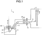
- FIG. 1 is a schematic view illustrating a constitution of the production apparatus according to one embodiment of the present invention used for producing the steel strip.
- FIG. 2 is a schematic view illustrating the constitution of the production apparatus of the steel strip on the exit side of a continuous annealing furnace illustrated in FIG. 1 .
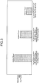
- FIG. 3 is a view illustrating one example of an outflow of a reducing gas in the continuous annealing furnace from a sealed part of the furnace when a seal roll device(s) and a seal plate device are installed.
- a production apparatus 1 of a steel strip is provided with a continuous annealing furnace 2, a snout 6, sealing devices 10 and 20 arranged on the entry side of the snout, a hot-dip-galvanizing tank 5, and bath equipment (an in-tank immersion sink roll 31, an in-tank support roll 32, a plated coating weight control device 33, and the like), as main constitutional features.
- the entry side of the snout includes a portion in which the snout 6 and the continuous annealing furnace 2 are connected with each other.
- a mixed gas of hydrogen and nitrogen having general hydrogen concentration of several percent by volume to several tens of percent by volume can be exemplified.
- Conditions, such as a hydrogen concentration and the amount of supply of the reducing gas, are properly set.
- the hot-dip-galvanizing tank 5 having a hot-dip-galvanizing bath in the inside thereof is configured to be movable between an online position at which hot dip galvanizing is applied to a steel strip S and an off-line position to which the hot-dip-galvanizing tank 5 is retracted when the hot dip galvanizing is not applied to the steel strip S.
- a movement mechanism of the hot-dip-galvanizing tank 5 a movement mechanism using a screw jack and a carriage can be exemplified.
- the steel strip S is, after passing through the snout 6, brought into the hot-dip-galvanizing tank 5, and pulled up from the hot-dip-galvanizing bath. Thereafter, galvanized coating weight is adjusted by the plated coating weight control devices, such as a gas wiping device.
- the steel strip S is cooled, or alloying treatment may be applied to the steel strip S.
- the alloying treatment is processing that reheats the steel strip S to a predetermined temperature by using an alloying furnace, such as an induction heating furnace and the like (not illustrated in the drawings), thus alloying the galvanized film adhered to the steel strip S.
- a seal plate device 10 and seal roll devices 20 arranged in two stages are arranged along the transfer direction of the steel strip S in this order between the exit side of the continuous annealing furnace 2 and the snout 6.
- the seal plate device 10 is a contact-type device in which a pair of seal plates 11a and 11b that face each other are brought into contact with the steel strip S during usual short-time line stop or when operation troubles force line stop thus preventing the atmospheric gas (reducing gas) in the continuous annealing furnace 2 from flowing to the outside of the furnace, and preventing the atmospheric air from entering into the furnace.
- a distance between the seal plate 11a and the seal plate 11b is controlled by opening/closing devices 12a and 12b.
- the seal roll device 20 is a noncontact-type device in which a pair of seal rolls 21a and 21b are brought closer to the steel strip S as necessary without being brought into contact with the steel strip S thus preventing the reducing gas in the continuous annealing furnace 2 from flowing to the outside of the furnace and preventing the atmospheric air from entering into the furnace.
- Each of the seal roll device 20 is capable of being independently controlled for each stage.
- a distance between the seal roll device 21a and the seal roll device 21b is controlled by opening/closing devices 22a and 22b.
- the seal plate device 10 and the seal roll devices 20 are arranged between the exit side of the continuous annealing furnace 2 and the entry side of the snout 6 thus preventing the reducing gas from flowing to the outside of the continuous annealing furnace 2 more effectively and preventing the atmospheric air from entering into the continuous annealing furnace 2 more effectively when switching between a hot-dip-plated steel strip producing route and a cold-rolled steel sheet producing route and when producing a cold-rolled steel sheet. Due to such constitution, it is possible to produce the hot-dip-plated steel strip or the cold-rolled steel strip without using complicated and large-scale equipment.
- the seal plate device 10 is a contact-type device that prevents the reducing gas from flowing to the outside of the furnace during line stop thus reducing the outflow of the reducing gas to the outside of the furnace as compared with the seal roll devices 20.
- the seal roll devices 20 are arranged in two stages because as illustrated in FIG. 3 , the seal roll devices 20 arranged in two stage further reduce the outflow of the reducing gas to the outside of the furnace compared with the case that the seal roll device 20 is arranged in one stage; and even when problems, such as foreign matter adhesion, occur in either one of the seal roll devices 20, it is possible to continue the operation by closing remaining seal roll device 20, while opening the seal roll device 20 in which the problems occur. It is undesirable to install the seal roll devices 20 arranged in three stages or more because of less advantageous effects considering the increase in cost of the production apparatus and the increase in space for installing the production apparatus.
- the seal plate device 10 and the seal roll devices 20 arranged in two stages are installed along the transfer direction of the steel strip S in this order because the checking and cleaning of the seal roll devices 20 can be easily performed in a state that the reducing gas is prevented from flowing to the outside of the furnace by using the seal plate device 10 during line stop.
- the checking and cleaning of the seal roll devices 20 are performed to reduce the occurrence of product defects attributed to the seal roll devices 20.
- the seal plate device 10 prevents the reducing gas from flowing to the outside of the furnace during line stop, the seal roll devices 20 can be opened in checking the seal roll devices 20. As a result, the checking and cleaning of the seal roll devices 20 become very easy.
- an inspection window 23 is arranged so that the seal roll devices 20 can be visually checked. Due to such constitution, the seal roll devices 20 can be easily checked by way of the inspection window 23. Furthermore, in at least one space out of a space between the seal plate device 10 and the seal roll devices 20 arranged in two stages, and a space between the seal roll devices 20 arranged in two stages and the snout 6, it is desirable to form a working space having a height of 1.5 m or more in the furnace.
- a hot-dip galvanized steel strip or a cold-rolled steel strip is produced by the following method, in the present invention.
- a steel-strip production method is explained for each of the case of switching from the producing of a hot-dip galvanized steel strip to the producing of a cold-rolled steel strip, and the case of switching from the producing of the cold-rolled steel strip to the producing of the hot-dip galvanized steel strip.
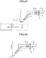
- FIG. 4A to FIG. 4D are schematic views each illustrating the operation of the production apparatus.
- FIG. 4A is a view illustrating a state where the hot-dip galvanized steel strip is produced.
- the seal plate device 10 is closed thus stopping the reducing gas in the continuous annealing furnace 2 from flowing to the outside of the furnace.
- bath equipment including the in-tank immersion sink roll 31, the in-tank support roll 32, the plated coating weight control device 33, and the like that are illustrated in FIG. 4A is removed.
- hot-dip-galvanizing tank 5 is moved from the online position to the off-line position.
- a deflector roll 40 is installed at the position of the in-tank immersion sink roll 31 to form the transfer path of the steel strip S for producing the cold-rolled steel strip.
- the transfer direction of the steel strip S after passing through the snout 6 is turned by the deflector roll 40.
- the seal plate device 10 is opened after closing the seal roll devices 20 thus preventing the reducing gas from flowing to the outside of the furnace and preventing the atmospheric air from entering into the furnace, using the seal roll devices 20. Thereafter, the transfer of the steel strip S is started, and the cold-rolled steel strip is produced.
- the transfer direction of the steel strip S is turned by the deflector roll 40 arranged at the position of the in-tank immersion sink roll 31 thus producing the cold-rolled steel strip with substantially the same transfer path and transfer length as in the case of the hot-dip galvanized steel strip. Furthermore, substantially the same location tracking calculation processing of the steel strip S can be used irrespective of the steel strip S to be produced and hence, only one location tracking program is required in a computer and program change processing becomes unnecessary, and therefore a system is simplified.
- the same transfer path of the steel strip S can be used and hence, a function and operation for tilting the snout 6 also become unnecessary thus reducing the cost of equipment.
- the opening and closing operations or the like of the continuous annealing furnace 2 become unnecessary and hence, the efforts and times required for switching between the opening and the closing of the continuous annealing furnace 2 can be reduced thus improving production efficiency.
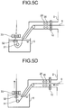
- FIG. 5A to FIG. 5D are schematic views each illustrating the operation of the production apparatus when switching from the producing of the cold-rolled steel strip to the producing of the hot-dip galvanized steel strip.
- FIG. 5A is a view illustrating a state where the cold-rolled steel strip is produced.
- the transfer of the steel strip S is stopped and, as illustrated in FIG. 5B , the seal plate device 10 is thereafter closed and the seal roll devices 20 are opened thus preventing the reducing gas from flowing to the outside of the furnace and preventing the atmospheric air from entering into the furnace, using the seal plate device 10.
- the deflector roll 40 is removed, and the hot-dip-galvanizing tank 5 is moved from the off-line position to the online position.
- the bath equipment including the in-tank immersion sink roll 31, the in-tank support roll 32, the plated coating weight control device 33, and the like is installed.
- the seal plate device 10 is opened. In this case, the snout 6 is hermetically closed thus preventing the reducing gas from flowing to the outside of the continuous annealing furnace and preventing the atmospheric air from entering into the furnace. Thereafter, the transfer of the steel strip S is started, and the hot-dip galvanized steel strip is produced.
- the transfer direction of the steel strip S after passing through the snout 6 is turned by the in-tank immersion sink roll 31 arranged at the position of the deflector roll 40.
- the hot-dip galvanized steel strip can be produced with substantially the same transfer path and transfer length as in the case of the cold-rolled steel strip.
- the seal plate device 10 and the seal roll devices 20 are opened, the steel strip S is transferred, and the steel strip S after being continuously annealed is brought into the hot-dip-plating tank 5.
- the seal plate device 10 When switching from the producing of the hot-dip-plated steel strip to the producing of the cold-rolled steel strip, the seal plate device 10 is closed, the hot-dip-galvanizing tank 5, the in-tank immersion sink roll 31, the in-tank support roll 32, and the plated coating weight control device 33 are thereafter moved to the off-line position, the deflector roll 40 is installed at the position of the in-tank immersion sink roll 31, the seal roll devices 20 are thereafter closed, and the seal plate device 10 is opened thus switching to the producing of the cold-rolled sheet steel.
- the seal plate device 10 when switching from the producing of the cold-rolled steel strip to the producing of the hot-dip-plated steel strip, the seal plate device 10 is closed, the seal roll devices 20 are thereafter opened, the hot-dip-galvanizing tank 5, the in-tank immersion sink roll 31, the in-tank support roll 32, and the plated coating weight control device 33 are moved to the online position, the distal end of the snout 6 is immersed in the hot-dip-galvanizing bath of the hot-dip-galvanizing tank 5, and the seal plate device 10 is thereafter opened thus switching to the producing of the hot-dip galvanized steel strip.
- the seal plate device 10 and the seal roll devices 20 can be used to prevent the reducing gas in the continuous annealing furnace 2 from flowing to the outside of the furnace and to prevent the atmospheric air from entering into the furnace. Furthermore, the in-tank immersion sink roll 31 and the deflector roll 40 are located at the same position and hence, the transfer direction of the steel strip S is turned at the same direction turning point irrespective of the type of the steel strip S thus the hot-dip galvanized steel strip and the cold-rolled steel strip can be produced with substantially the same transfer path and transfer length. As a result, the hot-dip galvanized steel strip and the cold-rolled steel strip can be produced without taking considerable amount of efforts and times, thus further simplifying the production apparatus and improving production efficiency.
- the present invention it is possible to provide a steel-strip production method, the method being capable of switching between the hot-dip-plated steel strip and the cold-rolled steel strip without taking considerable amount of efforts and times, while preventing the atmospheric gas in the continuous annealing furnace from flowing to the outside of the furnace and preventing the atmospheric air from entering into the furnace, and producing the steel strip with substantially the same transfer path and transfer length irrespective of the type of the steel strip.
Landscapes
- Chemical & Material Sciences (AREA)
- Engineering & Computer Science (AREA)
- Mechanical Engineering (AREA)
- Organic Chemistry (AREA)
- Materials Engineering (AREA)
- Metallurgy (AREA)
- Physics & Mathematics (AREA)
- Thermal Sciences (AREA)
- Crystallography & Structural Chemistry (AREA)
- General Engineering & Computer Science (AREA)
- Chemical Kinetics & Catalysis (AREA)
- Heat Treatment Of Strip Materials And Filament Materials (AREA)
- Coating With Molten Metal (AREA)
Abstract
Description
- The present invention relates to a steel-strip production method.
- In recent years, there has been proposed a production apparatus that produces a hot-dip-plated steel strip and a cold-rolled steel strip using the same equipment. To be more specific,
Patent Literature 1 describes a production apparatus provided with a continuous annealing furnace, hot dip plating equipment, and a bypass furnace that transfers a steel strip from the continuous annealing furnace to water quenching equipment without causing the steel strip to pass through the hot dip plating equipment. In the production apparatus, when producing the hot-dip-plated steel strip, the steel strip is transferred from the continuous annealing furnace to the hot dip plating equipment, and when producing the cold-rolled steel strip, the steel strip is transferred from the continuous annealing furnace to the water quenching equipment by way of the bypass furnace. - Patent Literature 1: Japanese Laid-open Patent Publication No.
2002-88414 - However, the production apparatus described in
Patent Literature 1 is provided with bypass furnace in order to switch a steel strip to be produced between the hot-dip-plated steel strip and the cold-rolled steel strip and hence, it is necessary to use a large-scale production apparatus, and it is difficult to design the production apparatus. Furthermore, since a path of the steel strip is changed when switching the steel strip to be produced, cutting and welding operations of the steel strip, and opening and closing operations of the continuous annealing furnace require considerable amount of efforts and times. - In general, in order to prevent oxidation of a steel sheet in the continuous annealing furnace, it is necessary to prevent an atmospheric air from being mixed into an atmospheric gas in the inside of the continuous annealing furnace when switching the steel strip to be produced. Furthermore, when the atmospheric air enters into the continuous annealing furnace, the oxygen or the like contained in the atmospheric air is required to be removed and hence, it is necessary to exchange the atmospheric gas in the continuous annealing furnace. However, in
Patent Literature 1, a measure to prevent the atmospheric air from entering into the continuous annealing furnace when switching the steel strip to be produced is not disclosed or suggested. In addition, in the production apparatus described inPatent Literature 1, the transfer path of the steel strip in producing the hot-dip-plated steel strip and the transfer path of the steel strip in producing the cold-rolled steel strip are different from each other and hence, it is necessary to change a program that controls transfer processes of the steel strip each time when switching the steel strip to be produced. - As described above, according to the production apparatus described in
Patent Literature 1, it is difficult to produce the hot-dip-plated steel strip and the cold-rolled steel strip using the same equipment without taking considerable amount of efforts and times, while preventing the atmospheric gas in the continuous annealing furnace from flowing to the outside of the furnace and preventing the atmospheric air from entering into the furnace. - The present invention has been made to overcome such problems, and it is an object of the present invention to provide a steel-strip production method, the method being capable of switching between the producing of the hot-dip-plated steel strip and the producing of the cold-rolled steel strip without taking considerable amount of efforts and times, and producing the steel strip with substantially the same transfer path and transfer length irrespective of the type of the steel strip, while preventing the atmospheric gas in the continuous annealing furnace from flowing to the outside of the furnace and preventing the atmospheric air from entering into the furnace.
- To solve the problem and achieve the object, a steel-strip production method according to the present invention is a method of producing a hot-dip-plated steel strip and a cold-rolled steel strip, the method being executed by a production apparatus including: a continuous annealing furnace; a snout connected to the continuous annealing furnace; a contact-type seal plate device and a noncontact-type seal roll device that are arranged on the entry side of the snout along the transfer direction of the steel strip in this order; a hot-dip-plating tank being movable; and a roll configured to turn the path direction of the steel strip after passing through the snout, wherein a hot-dip-plated steel strip production unit configured to produce the hot-dip-plated steel strip by bringing the steel strip continuously annealed in the continuous annealing furnace into the hot-dip-plating tank, and a cold-rolled steel strip production unit configured to produce the cold-rolled steel strip by transferring the steel strip continuously annealed in the continuous annealing furnace without causing the steel strip to pass through the hot-dip-plating tank are configured to be switchable with one another.
- Moreover, in the steel-strip production method according to the present invention, when producing the hot-dip-plated steel strip, opening the seal plate device and the seal roll device; and when producing the cold-rolled steel strip, opening the seal plate device and closing the seal roll device.
- Moreover, in the steel-strip production method according to the present invention, a sink roll which is the roll configured to turn the path direction of the steel strip when producing the hot-dip-plated steel strip, and a deflector roll which is the roll configured to turn the path direction of the steel strip when producing the cold-rolled steel strip are configured to switch in accordance with the type of the steel strip to be produced.
- Moreover, in the steel-strip production method according to the present invention, when switching from the producing of the hot-dip-plated steel strip to the producing of the cold-rolled steel strip: stopping the transfer of the steel strip; closing the seal plate device; removing an in-tank immersion sink roll and bath equipment, moving the hot-dip-plating tank from an online position to an off-line position; installing the deflector roll at the arrangement position of the in-tank immersion sink roll to form the transfer path when producing the cold-rolled steel strip; closing the seal roll device; and opening the seal plate device, and when switching from the producing of the cold-rolled steel strip to the producing of the hot-dip-plated steel strip: stopping the transfer of the steel strip; closing the seal plate; removing the deflector roll; moving the hot-dip-plating tank from the off-line position to the online position; installing the in-tank immersion sink roll and the bath equipment; and opening the seal plate device.
- Moreover, a steel-strip according to the present invention includes the steel-strip produced using the steel-strip production method according to the present invention.
- The steel-strip production method according to the present invention is capable of switching between the producing of the hot-dip-plated steel strip and the producing of the cold-rolled steel strip without taking considerable amount of efforts and times, and producing the steel strip with substantially the same transfer path and transfer length irrespective of the type of the steel strip, while preventing the atmospheric gas in the continuous annealing furnace from flowing to the outside of the furnace and preventing the atmospheric air from entering into the furnace.
-
-
FIG. 1 is a schematic view illustrating a constitution of a production apparatus of a steel strip according to one embodiment of the present invention. -
FIG. 2 is a schematic view illustrating the constitution of the production apparatus of the steel strip on the exit side of a continuous annealing furnace illustrated inFIG. 1 . -
FIG. 3 is a view illustrating one example of an outflow of a reducing gas in the continuous annealing furnace from a sealed part of the furnace when a seal roll device(s) and a seal plate device are installed. -
FIG. 4A is a schematic view illustrating the operation of the production apparatus when switching from the producing of the hot-dip galvanized steel strip to the producing of the cold-rolled steel strip. -
FIG. 4B is a schematic view illustrating the operation of the production apparatus when switching from the producing of the hot-dip galvanized steel strip to the producing of the cold-rolled steel strip. -
FIG. 4C is a schematic view illustrating the operation of the production apparatus when switching from the producing of the hot-dip galvanized steel strip to the producing of the cold-rolled steel strip. -
FIG. 4D is a schematic view illustrating the operation of the production apparatus when switching from the producing of the hot-dip galvanized steel strip to the producing of the cold-rolled steel strip. -
FIG. 5A is a schematic view illustrating the operation of the production apparatus when switching from the producing of the cold-rolled steel strip to the producing of the hot-dip galvanized steel strip. -
FIG. 5B is a schematic view illustrating the operation of the production apparatus when switching from the producing of the cold-rolled steel strip to the producing of the hot-dip galvanized steel strip. -
FIG. 5C is a schematic view illustrating the operation of the production apparatus when switching from the producing of the cold-rolled steel strip to the producing of the hot-dip galvanized steel strip. -
FIG. 5D is a schematic view illustrating the operation of the production apparatus when switching from the producing of the cold-rolled steel strip to the producing of the hot-dip galvanized steel strip. - Hereinafter, with reference to drawings, a steel-strip production method according to one embodiment of the present invention is specifically explained by taking a case where a hot-dip galvanized steel strip and a cold-rolled steel strip are produced, as an example.
- First of all, with reference to
FIG. 1 to FIG. 3 , the explanation is made with respect to the constitution of a production apparatus according to one embodiment of the present invention used for producing the steel strip. -
FIG. 1 is a schematic view illustrating a constitution of the production apparatus according to one embodiment of the present invention used for producing the steel strip.FIG. 2 is a schematic view illustrating the constitution of the production apparatus of the steel strip on the exit side of a continuous annealing furnace illustrated inFIG. 1 .FIG. 3 is a view illustrating one example of an outflow of a reducing gas in the continuous annealing furnace from a sealed part of the furnace when a seal roll device(s) and a seal plate device are installed. - As illustrated in
FIG. 1 , aproduction apparatus 1 of a steel strip according to one embodiment of the present invention is provided with a continuous annealingfurnace 2, asnout 6,sealing devices tank 5, and bath equipment (an in-tankimmersion sink roll 31, an in-tank support roll 32, a plated coatingweight control device 33, and the like), as main constitutional features. Here, the entry side of the snout includes a portion in which thesnout 6 and the continuous annealingfurnace 2 are connected with each other. - As the reducing gas in the continuous annealing
furnace 2, in order to prevent oxidation of the surfaces of the steel strip in annealing, a mixed gas of hydrogen and nitrogen having general hydrogen concentration of several percent by volume to several tens of percent by volume can be exemplified. Conditions, such as a hydrogen concentration and the amount of supply of the reducing gas, are properly set. - The hot-dip-galvanizing
tank 5 having a hot-dip-galvanizing bath in the inside thereof is configured to be movable between an online position at which hot dip galvanizing is applied to a steel strip S and an off-line position to which the hot-dip-galvanizingtank 5 is retracted when the hot dip galvanizing is not applied to the steel strip S. As a movement mechanism of the hot-dip-galvanizingtank 5, a movement mechanism using a screw jack and a carriage can be exemplified. In producing a hot-dip-plated steel strip, the steel strip S is, after passing through thesnout 6, brought into the hot-dip-galvanizingtank 5, and pulled up from the hot-dip-galvanizing bath. Thereafter, galvanized coating weight is adjusted by the plated coating weight control devices, such as a gas wiping device. - After a galvanized coating is formed, the steel strip S is cooled, or alloying treatment may be applied to the steel strip S. The alloying treatment is processing that reheats the steel strip S to a predetermined temperature by using an alloying furnace, such as an induction heating furnace and the like (not illustrated in the drawings), thus alloying the galvanized film adhered to the steel strip S.
- As illustrated in
FIG. 2 , aseal plate device 10 andseal roll devices 20 arranged in two stages are arranged along the transfer direction of the steel strip S in this order between the exit side of the continuous annealingfurnace 2 and thesnout 6. - The
seal plate device 10 is a contact-type device in which a pair ofseal plates furnace 2 from flowing to the outside of the furnace, and preventing the atmospheric air from entering into the furnace. A distance between theseal plate 11a and theseal plate 11b is controlled by opening/closing devices - The
seal roll device 20 is a noncontact-type device in which a pair ofseal rolls furnace 2 from flowing to the outside of the furnace and preventing the atmospheric air from entering into the furnace. Each of theseal roll device 20 is capable of being independently controlled for each stage. A distance between theseal roll device 21a and theseal roll device 21b is controlled by opening/closing devices - The
seal plate device 10 and theseal roll devices 20 are arranged between the exit side of thecontinuous annealing furnace 2 and the entry side of thesnout 6 thus preventing the reducing gas from flowing to the outside of thecontinuous annealing furnace 2 more effectively and preventing the atmospheric air from entering into thecontinuous annealing furnace 2 more effectively when switching between a hot-dip-plated steel strip producing route and a cold-rolled steel sheet producing route and when producing a cold-rolled steel sheet. Due to such constitution, it is possible to produce the hot-dip-plated steel strip or the cold-rolled steel strip without using complicated and large-scale equipment. - The
seal plate device 10 is a contact-type device that prevents the reducing gas from flowing to the outside of the furnace during line stop thus reducing the outflow of the reducing gas to the outside of the furnace as compared with theseal roll devices 20. Here, it may be possible to further prevent the reducing gas from flowing to the outside of the furnace by also closing theseal roll devices 20 during line stop. - The
seal roll devices 20 are arranged in two stages because as illustrated inFIG. 3 , theseal roll devices 20 arranged in two stage further reduce the outflow of the reducing gas to the outside of the furnace compared with the case that theseal roll device 20 is arranged in one stage; and even when problems, such as foreign matter adhesion, occur in either one of theseal roll devices 20, it is possible to continue the operation by closing remainingseal roll device 20, while opening theseal roll device 20 in which the problems occur. It is undesirable to install theseal roll devices 20 arranged in three stages or more because of less advantageous effects considering the increase in cost of the production apparatus and the increase in space for installing the production apparatus. - The
seal plate device 10 and theseal roll devices 20 arranged in two stages are installed along the transfer direction of the steel strip S in this order because the checking and cleaning of theseal roll devices 20 can be easily performed in a state that the reducing gas is prevented from flowing to the outside of the furnace by using theseal plate device 10 during line stop. The checking and cleaning of theseal roll devices 20 are performed to reduce the occurrence of product defects attributed to theseal roll devices 20. Furthermore, since theseal plate device 10 prevents the reducing gas from flowing to the outside of the furnace during line stop, theseal roll devices 20 can be opened in checking theseal roll devices 20. As a result, the checking and cleaning of theseal roll devices 20 become very easy. - In a furnace wall in the vicinity of the position where the
seal roll devices 20 are arranged, aninspection window 23 is arranged so that theseal roll devices 20 can be visually checked. Due to such constitution, theseal roll devices 20 can be easily checked by way of theinspection window 23. Furthermore, in at least one space out of a space between theseal plate device 10 and theseal roll devices 20 arranged in two stages, and a space between theseal roll devices 20 arranged in two stages and thesnout 6, it is desirable to form a working space having a height of 1.5 m or more in the furnace. Because such working space is formed, a worker can safely enter into the working space through the furnace wall in a safe state that the reducing gas hardly flows to the outside of the furnace through theseal plate device 10 during line stop, and can easily perform the checking and cleaning of theseal roll devices 20 in the working space. - By using the production apparatus of the steel strip having the above-described constitution, a hot-dip galvanized steel strip or a cold-rolled steel strip is produced by the following method, in the present invention. Hereinafter, with reference to
FIGS. 4A to 4D andFIGS. 5A to 5D , a steel-strip production method is explained for each of the case of switching from the producing of a hot-dip galvanized steel strip to the producing of a cold-rolled steel strip, and the case of switching from the producing of the cold-rolled steel strip to the producing of the hot-dip galvanized steel strip. - First of all, the explanation is made with respect to the steel-strip production method in the case of switching from the producing of the hot-dip galvanized steel strip to the producing of the cold-rolled steel strip.
-
FIG. 4A to FIG. 4D are schematic views each illustrating the operation of the production apparatus.FIG. 4A is a view illustrating a state where the hot-dip galvanized steel strip is produced. When switching from the state above to a state of producing of a cold-rolled steel strip, at first, after the transfer of the steel strip S is stopped, as illustrated inFIG. 4B , theseal plate device 10 is closed thus stopping the reducing gas in thecontinuous annealing furnace 2 from flowing to the outside of the furnace. Furthermore, bath equipment including the in-tankimmersion sink roll 31, the in-tank support roll 32, the plated coatingweight control device 33, and the like that are illustrated inFIG. 4A is removed. - Next, as illustrated in
FIG. 4C , hot-dip-galvanizingtank 5 is moved from the online position to the off-line position. Thereafter, adeflector roll 40 is installed at the position of the in-tankimmersion sink roll 31 to form the transfer path of the steel strip S for producing the cold-rolled steel strip. The transfer direction of the steel strip S after passing through thesnout 6 is turned by thedeflector roll 40. - Lastly, as illustrated in
FIG. 4D , theseal plate device 10 is opened after closing theseal roll devices 20 thus preventing the reducing gas from flowing to the outside of the furnace and preventing the atmospheric air from entering into the furnace, using theseal roll devices 20. Thereafter, the transfer of the steel strip S is started, and the cold-rolled steel strip is produced. - The transfer direction of the steel strip S is turned by the
deflector roll 40 arranged at the position of the in-tankimmersion sink roll 31 thus producing the cold-rolled steel strip with substantially the same transfer path and transfer length as in the case of the hot-dip galvanized steel strip. Furthermore, substantially the same location tracking calculation processing of the steel strip S can be used irrespective of the steel strip S to be produced and hence, only one location tracking program is required in a computer and program change processing becomes unnecessary, and therefore a system is simplified. - Furthermore, the same transfer path of the steel strip S can be used and hence, a function and operation for tilting the
snout 6 also become unnecessary thus reducing the cost of equipment. In addition, the opening and closing operations or the like of thecontinuous annealing furnace 2 become unnecessary and hence, the efforts and times required for switching between the opening and the closing of thecontinuous annealing furnace 2 can be reduced thus improving production efficiency. - Next, the explanation is made with respect to the steel-strip production method in the case of switching from the producing of the cold-rolled steel strip to the producing of the hot-dip galvanized steel strip.
-
FIG. 5A to FIG. 5D are schematic views each illustrating the operation of the production apparatus when switching from the producing of the cold-rolled steel strip to the producing of the hot-dip galvanized steel strip.FIG. 5A is a view illustrating a state where the cold-rolled steel strip is produced. When switching from the state above to a state of producing the hot-dip galvanized steel strip, at first, the transfer of the steel strip S is stopped and, as illustrated inFIG. 5B , theseal plate device 10 is thereafter closed and theseal roll devices 20 are opened thus preventing the reducing gas from flowing to the outside of the furnace and preventing the atmospheric air from entering into the furnace, using theseal plate device 10. Furthermore, thedeflector roll 40 is removed, and the hot-dip-galvanizingtank 5 is moved from the off-line position to the online position. - Next, as illustrated in
FIG. 5C , the bath equipment including the in-tankimmersion sink roll 31, the in-tank support roll 32, the plated coatingweight control device 33, and the like is installed. Lastly, as illustrated inFIG. 5D , after the immersion of the distal end of thesnout 6 in the hot-dip-galvanizing bath of the hot-dip-galvanizingtank 5, theseal plate device 10 is opened. In this case, thesnout 6 is hermetically closed thus preventing the reducing gas from flowing to the outside of the continuous annealing furnace and preventing the atmospheric air from entering into the furnace. Thereafter, the transfer of the steel strip S is started, and the hot-dip galvanized steel strip is produced. - The transfer direction of the steel strip S after passing through the
snout 6 is turned by the in-tankimmersion sink roll 31 arranged at the position of thedeflector roll 40. As a result, the hot-dip galvanized steel strip can be produced with substantially the same transfer path and transfer length as in the case of the cold-rolled steel strip. Thus, just as in the case of the cold-rolled steel strip mentioned above, the system is simplified, the cost of equipment is reduced, and the production efficiency is improved. - As can be clearly understood from the explanation above, in the steel-strip production method according to one embodiment of the present invention, when producing the hot-dip-plated steel strip, the
seal plate device 10 and theseal roll devices 20 are opened, the steel strip S is transferred, and the steel strip S after being continuously annealed is brought into the hot-dip-plating tank 5. - When switching from the producing of the hot-dip-plated steel strip to the producing of the cold-rolled steel strip, the
seal plate device 10 is closed, the hot-dip-galvanizingtank 5, the in-tankimmersion sink roll 31, the in-tank support roll 32, and the plated coatingweight control device 33 are thereafter moved to the off-line position, thedeflector roll 40 is installed at the position of the in-tankimmersion sink roll 31, theseal roll devices 20 are thereafter closed, and theseal plate device 10 is opened thus switching to the producing of the cold-rolled sheet steel. - On the other hand, when switching from the producing of the cold-rolled steel strip to the producing of the hot-dip-plated steel strip, the
seal plate device 10 is closed, theseal roll devices 20 are thereafter opened, the hot-dip-galvanizingtank 5, the in-tankimmersion sink roll 31, the in-tank support roll 32, and the plated coatingweight control device 33 are moved to the online position, the distal end of thesnout 6 is immersed in the hot-dip-galvanizing bath of the hot-dip-galvanizingtank 5, and theseal plate device 10 is thereafter opened thus switching to the producing of the hot-dip galvanized steel strip. - Due to such constitution, the
seal plate device 10 and theseal roll devices 20 can be used to prevent the reducing gas in thecontinuous annealing furnace 2 from flowing to the outside of the furnace and to prevent the atmospheric air from entering into the furnace. Furthermore, the in-tankimmersion sink roll 31 and thedeflector roll 40 are located at the same position and hence, the transfer direction of the steel strip S is turned at the same direction turning point irrespective of the type of the steel strip S thus the hot-dip galvanized steel strip and the cold-rolled steel strip can be produced with substantially the same transfer path and transfer length. As a result, the hot-dip galvanized steel strip and the cold-rolled steel strip can be produced without taking considerable amount of efforts and times, thus further simplifying the production apparatus and improving production efficiency. - Heretofore, although the embodiment to which the invention made by inventors is applied has been explained in conjunction with drawings, the present invention is not limited to the description and the drawings by way of the above-mentioned embodiment that merely constitutes one embodiment of the present invention. For example, with respect to plating, not only the hot dip galvanizing but also the aluminum plating, the composite plating of zinc and aluminum, or the like may be used. Furthermore, the steel grade of the cold-rolled steel strip is not limited in particular. In this manner, various modifications, embodiment examples, and techniques conceivable of by those skilled in the art or the like based on the present embodiment are arbitrarily conceivable without departing from the gist of the present invention.
- According to the present invention, it is possible to provide a steel-strip production method, the method being capable of switching between the hot-dip-plated steel strip and the cold-rolled steel strip without taking considerable amount of efforts and times, while preventing the atmospheric gas in the continuous annealing furnace from flowing to the outside of the furnace and preventing the atmospheric air from entering into the furnace, and producing the steel strip with substantially the same transfer path and transfer length irrespective of the type of the steel strip.
-
- 1
- production apparatus of steel strip
- 2
- continuous annealing furnace
- 5
- hot-dip-galvanizing tank
- 6
- snout
- 10
- seal plate device
- 20
- seal roll device
- 31
- in-tank immersion sink roll
- 32
- in-tank support roll
- 33
- plated coating weight control device
- 40
- deflector roll
- S
- steel strip
Claims (5)
- A steel-strip production method of producing a hot-dip-plated steel strip and a cold-rolled steel strip, the method being executed by a production apparatus including:a continuous annealing furnace; a snout connected to the continuous annealing furnace; a contact-type seal plate device and a noncontact-type seal roll device that are arranged on the entry side of the snout along the transfer direction of the steel strip in this order; a hot-dip-plating tank being movable; and a roll configured to turn the path direction of the steel strip after passing through the snout, whereina hot-dip-plated steel strip production unit configured to produce the hot-dip-plated steel strip by bringing the steel strip continuously annealed in the continuous annealing furnace into the hot-dip-plating tank, and a cold-rolled steel strip production unit configured to produce the cold-rolled steel strip by transferring the steel strip continuously annealed in the continuous annealing furnace without causing the steel strip to pass through the hot-dip-plating tank are configured to be switchable with one another.
- The steel-strip production method according to claim 1, wherein
when producing the hot-dip-plated steel strip, opening the seal plate device and the seal roll device; and
when producing the cold-rolled steel strip, opening the seal plate device and closing the seal roll device. - The steel-strip production method according to claim 1, wherein
a sink roll which is the roll configured to turn the path direction of the steel strip when producing the hot-dip-plated steel strip, and a deflector roll which is the roll configured to turn the path direction of the steel strip when producing the cold-rolled steel strip are configured to switch in accordance with the type of the steel strip to be produced. - The steel-strip production method according to any one of claims 1 to 3, wherein
when switching from the producing of the hot-dip-plated steel strip to the producing of the cold-rolled steel strip:stopping the transfer of the steel strip;closing the seal plate device;removing an in-tank immersion sink roll and bath equipment,moving the hot-dip-plating tank from an online position to an off-line position;installing the deflector roll at the arrangement position of the in-tank immersion sink roll to form the transfer path when producing the cold-rolled steel strip;closing the seal roll device; andopening the seal plate device, andwhen switching from the producing of the cold-rolled steel strip to the producing of the hot-dip-plated steel strip: stopping the transfer of the steel strip;closing the seal plate;removing the deflector roll;moving the hot-dip-plating tank from the off-line position to the online position;installing the in-tank immersion sink roll and the bath equipment; andopening the seal plate device. - A steel-strip produced using the steel-strip production method according to any one of claims 1 to 4.
Applications Claiming Priority (2)
| Application Number | Priority Date | Filing Date | Title |
|---|---|---|---|
| JP2014163562A JP6451138B2 (en) | 2014-08-11 | 2014-08-11 | Steel strip manufacturing method |
| PCT/JP2015/072473 WO2016024536A1 (en) | 2014-08-11 | 2015-08-07 | Steel-strip production method, and steel strip |
Publications (3)
| Publication Number | Publication Date |
|---|---|
| EP3181708A1 true EP3181708A1 (en) | 2017-06-21 |
| EP3181708A4 EP3181708A4 (en) | 2018-01-03 |
| EP3181708B1 EP3181708B1 (en) | 2019-12-11 |
Family
ID=55304164
Family Applications (1)
| Application Number | Title | Priority Date | Filing Date |
|---|---|---|---|
| EP15831909.5A Active EP3181708B1 (en) | 2014-08-11 | 2015-08-07 | Steel-strip production method |
Country Status (11)
| Country | Link |
|---|---|
| US (1) | US12366409B2 (en) |
| EP (1) | EP3181708B1 (en) |
| JP (1) | JP6451138B2 (en) |
| KR (1) | KR101971376B1 (en) |
| CN (2) | CN106661661A (en) |
| BR (1) | BR112017002455A2 (en) |
| MX (1) | MX376454B (en) |
| MY (1) | MY172660A (en) |
| RU (1) | RU2672963C2 (en) |
| WO (1) | WO2016024536A1 (en) |
| ZA (1) | ZA201701012B (en) |
Families Citing this family (5)
| Publication number | Priority date | Publication date | Assignee | Title |
|---|---|---|---|---|
| RU2769680C2 (en) * | 2019-06-13 | 2022-04-05 | Сергей Александрович Ненашев | Device for manufacturing steel tape |
| CN110904316B (en) * | 2019-12-23 | 2024-10-11 | 海盐大宁紧固件股份有限公司 | Nut continuous quenching device |
| CN115103925B (en) * | 2020-02-12 | 2025-06-06 | 日本制铁株式会社 | Roll surface condition determination assisting device, roll surface impurity removal device, and roll surface impurity removal method |
| CN112626435A (en) * | 2020-11-30 | 2021-04-09 | 日照宝华新材料有限公司 | Method for switching pickling production and galvanizing production of same unit |
| CN116770047B (en) * | 2023-06-30 | 2024-03-26 | 索罗曼(广州)新材料有限公司 | Titanium flat strip annealing device |
Family Cites Families (24)
| Publication number | Priority date | Publication date | Assignee | Title |
|---|---|---|---|---|
| US4049372A (en) * | 1976-05-04 | 1977-09-20 | Allegheny Ludlum Industries, Inc. | Apparatus for supporting and removing a work supporting roll |
| JPS53132437A (en) * | 1977-04-26 | 1978-11-18 | Nippon Steel Corp | Continuous treatment facilities for cold rolled steel band |
| JPS62127427A (en) * | 1985-11-26 | 1987-06-09 | Daido Steel Co Ltd | Continuous bright annealing furnace |
| JPS62147427A (en) * | 1985-12-21 | 1987-07-01 | Stanley Electric Co Ltd | Manufacturing method of liquid crystal display element |
| JPH075997B2 (en) * | 1986-10-06 | 1995-01-25 | 川崎製鉄株式会社 | High-temperature gas sealing device for furnace opening of non-oxidizing furnace |
| JPH01142068A (en) * | 1987-11-27 | 1989-06-02 | Nippon Steel Corp | Production of both cold rolled steel sheet and hot dip plated steel sheet |
| JP2590152B2 (en) * | 1987-12-04 | 1997-03-12 | 株式会社日立製作所 | Continuous melting plating and annealing equipment |
| JPH059592A (en) | 1991-07-09 | 1993-01-19 | Nkk Corp | Continuous annealing furnace |
| JP3258786B2 (en) | 1993-10-26 | 2002-02-18 | 川崎製鉄株式会社 | Transfer route switching method and apparatus for hot-dip coated steel sheet and cold-rolled steel sheet |
| JPH0810819A (en) * | 1994-06-24 | 1996-01-16 | Kawasaki Steel Corp | Method and apparatus for changing the transport path of steel strip in a production line for both hot dip plated steel sheet and cold rolled steel sheet |
| JPH11279731A (en) | 1998-03-31 | 1999-10-12 | Nippon Steel Corp | Continuous hot-dip plating and annealing equipment |
| JP3569439B2 (en) | 1998-04-01 | 2004-09-22 | 新日本製鐵株式会社 | Continuous hot-dip plating method and apparatus |
| US6341955B1 (en) * | 1998-10-23 | 2002-01-29 | Kawasaki Steel Corporation | Sealing apparatus in continuous heat-treatment furnace and sealing method |
| JP2002088414A (en) | 2000-09-13 | 2002-03-27 | Nippon Steel Corp | Equipment for combined use of continuous annealing and hot-dip plating |
| JP4728494B2 (en) * | 2001-03-13 | 2011-07-20 | 新日本製鐵株式会社 | Facilities for continuous annealing and hot dipping |
| JP4028990B2 (en) * | 2002-02-21 | 2008-01-09 | 新日本製鐵株式会社 | Combined production line for cold-rolled steel sheet and hot-dip galvanized steel sheet |
| JP3766652B2 (en) | 2002-09-06 | 2006-04-12 | 新日本製鐵株式会社 | Continuous hot-dip plating and continuous annealing method and apparatus for steel plate |
| JP4427527B2 (en) * | 2006-07-20 | 2010-03-10 | 三菱日立製鉄機械株式会社 | Surface-treated steel sheet manufacturing equipment |
| JP5058769B2 (en) * | 2007-01-09 | 2012-10-24 | 新日本製鐵株式会社 | Manufacturing method and manufacturing equipment for high strength cold-rolled steel sheet excellent in chemical conversion processability |
| CN101812579B (en) * | 2009-02-25 | 2012-04-11 | 宝山钢铁股份有限公司 | Flexible strip steel treating line suitable for producing various high-strength steel |
| JP2010215990A (en) | 2009-03-18 | 2010-09-30 | Nippon Steel Engineering Co Ltd | Dual-purpose facility for continuous annealing and hot-dip plating |
| KR101324899B1 (en) | 2009-10-01 | 2013-11-04 | 신닛테츠스미킨 카부시키카이샤 | Facility used for both continuous hot-dip coating and continuous annealing |
| CN101993997B (en) | 2010-12-10 | 2012-02-29 | 中冶南方(武汉)威仕工业炉有限公司 | Telescopic furnace nose capable of swinging |
| CN201915140U (en) | 2010-12-17 | 2011-08-03 | 鞍钢新轧-蒂森克虏伯镀锌钢板有限公司 | Novel furnace nose structure for continuous hot dip galvanizing steel belt |
-
2014
- 2014-08-11 JP JP2014163562A patent/JP6451138B2/en active Active
-
2015
- 2015-08-07 US US15/500,699 patent/US12366409B2/en active Active
- 2015-08-07 KR KR1020177003116A patent/KR101971376B1/en active Active
- 2015-08-07 MY MYPI2017700404A patent/MY172660A/en unknown
- 2015-08-07 BR BR112017002455A patent/BR112017002455A2/en not_active IP Right Cessation
- 2015-08-07 RU RU2017104231A patent/RU2672963C2/en not_active IP Right Cessation
- 2015-08-07 MX MX2017001836A patent/MX376454B/en active IP Right Grant
- 2015-08-07 WO PCT/JP2015/072473 patent/WO2016024536A1/en not_active Ceased
- 2015-08-07 EP EP15831909.5A patent/EP3181708B1/en active Active
- 2015-08-07 CN CN201580042820.XA patent/CN106661661A/en active Pending
- 2015-08-07 CN CN202111240182.6A patent/CN114058832A/en active Pending
-
2017
- 2017-02-09 ZA ZA2017/01012A patent/ZA201701012B/en unknown
Also Published As
| Publication number | Publication date |
|---|---|
| KR20170026614A (en) | 2017-03-08 |
| MX2017001836A (en) | 2017-04-27 |
| KR101971376B1 (en) | 2019-04-22 |
| ZA201701012B (en) | 2018-11-28 |
| US12366409B2 (en) | 2025-07-22 |
| CN106661661A (en) | 2017-05-10 |
| RU2672963C2 (en) | 2018-11-21 |
| JP6451138B2 (en) | 2019-01-16 |
| BR112017002455A2 (en) | 2017-12-05 |
| WO2016024536A1 (en) | 2016-02-18 |
| MY172660A (en) | 2019-12-09 |
| EP3181708B1 (en) | 2019-12-11 |
| JP2016037659A (en) | 2016-03-22 |
| CN114058832A (en) | 2022-02-18 |
| US20170219288A1 (en) | 2017-08-03 |
| MX376454B (en) | 2025-03-07 |
| EP3181708A4 (en) | 2018-01-03 |
Similar Documents
| Publication | Publication Date | Title |
|---|---|---|
| US10273557B2 (en) | Steel-strip production apparatus | |
| US12366409B2 (en) | Steel-strip production method, and steel strip | |
| JP6011740B2 (en) | Continuous molten metal plating method, hot dip galvanized steel strip, and continuous molten metal plating facility | |
| KR102559707B1 (en) | Method for dip-coating a metal strip | |
| KR101656283B1 (en) | Continuous galvanizing line | |
| RU2007121258A (en) | CONTROLLABLE DECREASE OF THE THICKNESS OF THE HOT-STEELED STEEL TAPE COATED BY THE MELT DIP AND THE APPLICABLE INSTALLATION | |
| RU2255138C2 (en) | Installation of dual-purpose assignment for a continuous annealing and application of a coating by dipping into a hot bath | |
| US7601221B2 (en) | Device for hot-dip coating a metal bar | |
| JP2008024981A (en) | Facility of manufacturing surface-treated steel sheet | |
| AU2006265394B2 (en) | Method and device for hot-dip coating a metal strip | |
| CN105339520A (en) | Combined treatment equipment for hot dip galvanizing of steel plate and continuous annealing | |
| JPH0728958U (en) | Continuous annealing / hot dipping treatment equipment | |
| JP3302280B2 (en) | Hot-dip metal plating apparatus and hot-dip metal plating method | |
| JPH01142068A (en) | Production of both cold rolled steel sheet and hot dip plated steel sheet | |
| KR20150073311A (en) | Plating Apparatus | |
| KR20150073312A (en) | Plating Apparatus | |
| JPH0651263U (en) | Continuous hot dip plating equipment |
Legal Events
| Date | Code | Title | Description |
|---|---|---|---|
| STAA | Information on the status of an ep patent application or granted ep patent |
Free format text: STATUS: THE INTERNATIONAL PUBLICATION HAS BEEN MADE |
|
| PUAI | Public reference made under article 153(3) epc to a published international application that has entered the european phase |
Free format text: ORIGINAL CODE: 0009012 |
|
| STAA | Information on the status of an ep patent application or granted ep patent |
Free format text: STATUS: REQUEST FOR EXAMINATION WAS MADE |
|
| 17P | Request for examination filed |
Effective date: 20170206 |
|
| AK | Designated contracting states |
Kind code of ref document: A1 Designated state(s): AL AT BE BG CH CY CZ DE DK EE ES FI FR GB GR HR HU IE IS IT LI LT LU LV MC MK MT NL NO PL PT RO RS SE SI SK SM TR |
|
| AX | Request for extension of the european patent |
Extension state: BA ME |
|
| DAV | Request for validation of the european patent (deleted) | ||
| DAX | Request for extension of the european patent (deleted) | ||
| A4 | Supplementary search report drawn up and despatched |
Effective date: 20171201 |
|
| RIC1 | Information provided on ipc code assigned before grant |
Ipc: F27B 9/30 20060101ALI20171128BHEP Ipc: C21D 8/04 20060101ALI20171128BHEP Ipc: F27B 9/36 20060101ALI20171128BHEP Ipc: C21D 1/74 20060101ALI20171128BHEP Ipc: C21D 9/56 20060101AFI20171128BHEP Ipc: B05C 3/132 20060101ALI20171128BHEP Ipc: B05C 3/12 20060101ALI20171128BHEP Ipc: B05C 3/02 20060101ALI20171128BHEP Ipc: C23C 2/00 20060101ALI20171128BHEP |
|
| STAA | Information on the status of an ep patent application or granted ep patent |
Free format text: STATUS: EXAMINATION IS IN PROGRESS |
|
| 17Q | First examination report despatched |
Effective date: 20181203 |
|
| REG | Reference to a national code |
Ref country code: DE Ref legal event code: R079 Ref document number: 602015043597 Country of ref document: DE Free format text: PREVIOUS MAIN CLASS: C21D0009560000 Ipc: C21D0008020000 |
|
| GRAP | Despatch of communication of intention to grant a patent |
Free format text: ORIGINAL CODE: EPIDOSNIGR1 |
|
| STAA | Information on the status of an ep patent application or granted ep patent |
Free format text: STATUS: GRANT OF PATENT IS INTENDED |
|
| RIC1 | Information provided on ipc code assigned before grant |
Ipc: F27B 9/36 20060101ALI20190711BHEP Ipc: C21D 9/56 20060101ALI20190711BHEP Ipc: C21D 8/02 20060101AFI20190711BHEP Ipc: F27B 9/30 20060101ALI20190711BHEP Ipc: B05C 3/132 20060101ALI20190711BHEP Ipc: B05C 3/02 20060101ALI20190711BHEP Ipc: B05C 3/12 20060101ALI20190711BHEP |
|
| INTG | Intention to grant announced |
Effective date: 20190730 |
|
| GRAS | Grant fee paid |
Free format text: ORIGINAL CODE: EPIDOSNIGR3 |
|
| GRAA | (expected) grant |
Free format text: ORIGINAL CODE: 0009210 |
|
| STAA | Information on the status of an ep patent application or granted ep patent |
Free format text: STATUS: THE PATENT HAS BEEN GRANTED |
|
| AK | Designated contracting states |
Kind code of ref document: B1 Designated state(s): AL AT BE BG CH CY CZ DE DK EE ES FI FR GB GR HR HU IE IS IT LI LT LU LV MC MK MT NL NO PL PT RO RS SE SI SK SM TR |
|
| REG | Reference to a national code |
Ref country code: GB Ref legal event code: FG4D |
|
| REG | Reference to a national code |
Ref country code: CH Ref legal event code: EP |
|
| REG | Reference to a national code |
Ref country code: AT Ref legal event code: REF Ref document number: 1212240 Country of ref document: AT Kind code of ref document: T Effective date: 20191215 |
|
| REG | Reference to a national code |
Ref country code: DE Ref legal event code: R096 Ref document number: 602015043597 Country of ref document: DE |
|
| REG | Reference to a national code |
Ref country code: IE Ref legal event code: FG4D |
|
| REG | Reference to a national code |
Ref country code: NL Ref legal event code: MP Effective date: 20191211 |
|
| REG | Reference to a national code |
Ref country code: LT Ref legal event code: MG4D |
|
| PG25 | Lapsed in a contracting state [announced via postgrant information from national office to epo] |
Ref country code: LT Free format text: LAPSE BECAUSE OF FAILURE TO SUBMIT A TRANSLATION OF THE DESCRIPTION OR TO PAY THE FEE WITHIN THE PRESCRIBED TIME-LIMIT Effective date: 20191211 Ref country code: GR Free format text: LAPSE BECAUSE OF FAILURE TO SUBMIT A TRANSLATION OF THE DESCRIPTION OR TO PAY THE FEE WITHIN THE PRESCRIBED TIME-LIMIT Effective date: 20200312 Ref country code: FI Free format text: LAPSE BECAUSE OF FAILURE TO SUBMIT A TRANSLATION OF THE DESCRIPTION OR TO PAY THE FEE WITHIN THE PRESCRIBED TIME-LIMIT Effective date: 20191211 Ref country code: BG Free format text: LAPSE BECAUSE OF FAILURE TO SUBMIT A TRANSLATION OF THE DESCRIPTION OR TO PAY THE FEE WITHIN THE PRESCRIBED TIME-LIMIT Effective date: 20200311 Ref country code: NO Free format text: LAPSE BECAUSE OF FAILURE TO SUBMIT A TRANSLATION OF THE DESCRIPTION OR TO PAY THE FEE WITHIN THE PRESCRIBED TIME-LIMIT Effective date: 20200311 Ref country code: SE Free format text: LAPSE BECAUSE OF FAILURE TO SUBMIT A TRANSLATION OF THE DESCRIPTION OR TO PAY THE FEE WITHIN THE PRESCRIBED TIME-LIMIT Effective date: 20191211 Ref country code: LV Free format text: LAPSE BECAUSE OF FAILURE TO SUBMIT A TRANSLATION OF THE DESCRIPTION OR TO PAY THE FEE WITHIN THE PRESCRIBED TIME-LIMIT Effective date: 20191211 |
|
| PG25 | Lapsed in a contracting state [announced via postgrant information from national office to epo] |
Ref country code: RS Free format text: LAPSE BECAUSE OF FAILURE TO SUBMIT A TRANSLATION OF THE DESCRIPTION OR TO PAY THE FEE WITHIN THE PRESCRIBED TIME-LIMIT Effective date: 20191211 Ref country code: HR Free format text: LAPSE BECAUSE OF FAILURE TO SUBMIT A TRANSLATION OF THE DESCRIPTION OR TO PAY THE FEE WITHIN THE PRESCRIBED TIME-LIMIT Effective date: 20191211 |
|
| PG25 | Lapsed in a contracting state [announced via postgrant information from national office to epo] |
Ref country code: AL Free format text: LAPSE BECAUSE OF FAILURE TO SUBMIT A TRANSLATION OF THE DESCRIPTION OR TO PAY THE FEE WITHIN THE PRESCRIBED TIME-LIMIT Effective date: 20191211 |
|
| PG25 | Lapsed in a contracting state [announced via postgrant information from national office to epo] |
Ref country code: RO Free format text: LAPSE BECAUSE OF FAILURE TO SUBMIT A TRANSLATION OF THE DESCRIPTION OR TO PAY THE FEE WITHIN THE PRESCRIBED TIME-LIMIT Effective date: 20191211 Ref country code: CZ Free format text: LAPSE BECAUSE OF FAILURE TO SUBMIT A TRANSLATION OF THE DESCRIPTION OR TO PAY THE FEE WITHIN THE PRESCRIBED TIME-LIMIT Effective date: 20191211 Ref country code: EE Free format text: LAPSE BECAUSE OF FAILURE TO SUBMIT A TRANSLATION OF THE DESCRIPTION OR TO PAY THE FEE WITHIN THE PRESCRIBED TIME-LIMIT Effective date: 20191211 Ref country code: PT Free format text: LAPSE BECAUSE OF FAILURE TO SUBMIT A TRANSLATION OF THE DESCRIPTION OR TO PAY THE FEE WITHIN THE PRESCRIBED TIME-LIMIT Effective date: 20200506 Ref country code: NL Free format text: LAPSE BECAUSE OF FAILURE TO SUBMIT A TRANSLATION OF THE DESCRIPTION OR TO PAY THE FEE WITHIN THE PRESCRIBED TIME-LIMIT Effective date: 20191211 Ref country code: ES Free format text: LAPSE BECAUSE OF FAILURE TO SUBMIT A TRANSLATION OF THE DESCRIPTION OR TO PAY THE FEE WITHIN THE PRESCRIBED TIME-LIMIT Effective date: 20191211 |
|
| PG25 | Lapsed in a contracting state [announced via postgrant information from national office to epo] |
Ref country code: SK Free format text: LAPSE BECAUSE OF FAILURE TO SUBMIT A TRANSLATION OF THE DESCRIPTION OR TO PAY THE FEE WITHIN THE PRESCRIBED TIME-LIMIT Effective date: 20191211 Ref country code: SM Free format text: LAPSE BECAUSE OF FAILURE TO SUBMIT A TRANSLATION OF THE DESCRIPTION OR TO PAY THE FEE WITHIN THE PRESCRIBED TIME-LIMIT Effective date: 20191211 Ref country code: IS Free format text: LAPSE BECAUSE OF FAILURE TO SUBMIT A TRANSLATION OF THE DESCRIPTION OR TO PAY THE FEE WITHIN THE PRESCRIBED TIME-LIMIT Effective date: 20200411 |
|
| REG | Reference to a national code |
Ref country code: DE Ref legal event code: R097 Ref document number: 602015043597 Country of ref document: DE |
|
| REG | Reference to a national code |
Ref country code: AT Ref legal event code: MK05 Ref document number: 1212240 Country of ref document: AT Kind code of ref document: T Effective date: 20191211 |
|
| PLBE | No opposition filed within time limit |
Free format text: ORIGINAL CODE: 0009261 |
|
| STAA | Information on the status of an ep patent application or granted ep patent |
Free format text: STATUS: NO OPPOSITION FILED WITHIN TIME LIMIT |
|
| PG25 | Lapsed in a contracting state [announced via postgrant information from national office to epo] |
Ref country code: DK Free format text: LAPSE BECAUSE OF FAILURE TO SUBMIT A TRANSLATION OF THE DESCRIPTION OR TO PAY THE FEE WITHIN THE PRESCRIBED TIME-LIMIT Effective date: 20191211 |
|
| 26N | No opposition filed |
Effective date: 20200914 |
|
| PG25 | Lapsed in a contracting state [announced via postgrant information from national office to epo] |
Ref country code: AT Free format text: LAPSE BECAUSE OF FAILURE TO SUBMIT A TRANSLATION OF THE DESCRIPTION OR TO PAY THE FEE WITHIN THE PRESCRIBED TIME-LIMIT Effective date: 20191211 Ref country code: SI Free format text: LAPSE BECAUSE OF FAILURE TO SUBMIT A TRANSLATION OF THE DESCRIPTION OR TO PAY THE FEE WITHIN THE PRESCRIBED TIME-LIMIT Effective date: 20191211 |
|
| PG25 | Lapsed in a contracting state [announced via postgrant information from national office to epo] |
Ref country code: IT Free format text: LAPSE BECAUSE OF FAILURE TO SUBMIT A TRANSLATION OF THE DESCRIPTION OR TO PAY THE FEE WITHIN THE PRESCRIBED TIME-LIMIT Effective date: 20191211 |
|
| PG25 | Lapsed in a contracting state [announced via postgrant information from national office to epo] |
Ref country code: PL Free format text: LAPSE BECAUSE OF FAILURE TO SUBMIT A TRANSLATION OF THE DESCRIPTION OR TO PAY THE FEE WITHIN THE PRESCRIBED TIME-LIMIT Effective date: 20191211 |
|
| PG25 | Lapsed in a contracting state [announced via postgrant information from national office to epo] |
Ref country code: MC Free format text: LAPSE BECAUSE OF FAILURE TO SUBMIT A TRANSLATION OF THE DESCRIPTION OR TO PAY THE FEE WITHIN THE PRESCRIBED TIME-LIMIT Effective date: 20191211 |
|
| REG | Reference to a national code |
Ref country code: CH Ref legal event code: PL |
|
| PG25 | Lapsed in a contracting state [announced via postgrant information from national office to epo] |
Ref country code: LU Free format text: LAPSE BECAUSE OF NON-PAYMENT OF DUE FEES Effective date: 20200807 Ref country code: LI Free format text: LAPSE BECAUSE OF NON-PAYMENT OF DUE FEES Effective date: 20200831 Ref country code: CH Free format text: LAPSE BECAUSE OF NON-PAYMENT OF DUE FEES Effective date: 20200831 |
|
| REG | Reference to a national code |
Ref country code: BE Ref legal event code: MM Effective date: 20200831 |
|
| PG25 | Lapsed in a contracting state [announced via postgrant information from national office to epo] |
Ref country code: IE Free format text: LAPSE BECAUSE OF NON-PAYMENT OF DUE FEES Effective date: 20200807 Ref country code: BE Free format text: LAPSE BECAUSE OF NON-PAYMENT OF DUE FEES Effective date: 20200831 |
|
| PG25 | Lapsed in a contracting state [announced via postgrant information from national office to epo] |
Ref country code: MT Free format text: LAPSE BECAUSE OF FAILURE TO SUBMIT A TRANSLATION OF THE DESCRIPTION OR TO PAY THE FEE WITHIN THE PRESCRIBED TIME-LIMIT Effective date: 20191211 Ref country code: CY Free format text: LAPSE BECAUSE OF FAILURE TO SUBMIT A TRANSLATION OF THE DESCRIPTION OR TO PAY THE FEE WITHIN THE PRESCRIBED TIME-LIMIT Effective date: 20191211 |
|
| PG25 | Lapsed in a contracting state [announced via postgrant information from national office to epo] |
Ref country code: MK Free format text: LAPSE BECAUSE OF FAILURE TO SUBMIT A TRANSLATION OF THE DESCRIPTION OR TO PAY THE FEE WITHIN THE PRESCRIBED TIME-LIMIT Effective date: 20191211 |
|
| PGFP | Annual fee paid to national office [announced via postgrant information from national office to epo] |
Ref country code: DE Payment date: 20250702 Year of fee payment: 11 |
|
| PGFP | Annual fee paid to national office [announced via postgrant information from national office to epo] |
Ref country code: TR Payment date: 20250725 Year of fee payment: 11 |
|
| PGFP | Annual fee paid to national office [announced via postgrant information from national office to epo] |
Ref country code: GB Payment date: 20250703 Year of fee payment: 11 |
|
| PGFP | Annual fee paid to national office [announced via postgrant information from national office to epo] |
Ref country code: FR Payment date: 20250703 Year of fee payment: 11 |