EP3181482A1 - Rigid pack for tobacco articles - Google Patents
Rigid pack for tobacco articles Download PDFInfo
- Publication number
- EP3181482A1 EP3181482A1 EP16203679.2A EP16203679A EP3181482A1 EP 3181482 A1 EP3181482 A1 EP 3181482A1 EP 16203679 A EP16203679 A EP 16203679A EP 3181482 A1 EP3181482 A1 EP 3181482A1
- Authority
- EP
- European Patent Office
- Prior art keywords
- collar
- wall
- pack
- inner wrap
- container
- Prior art date
- Legal status (The legal status is an assumption and is not a legal conclusion. Google has not performed a legal analysis and makes no representation as to the accuracy of the status listed.)
- Granted
Links
Images








Classifications
-
- B—PERFORMING OPERATIONS; TRANSPORTING
- B65—CONVEYING; PACKING; STORING; HANDLING THIN OR FILAMENTARY MATERIAL
- B65D—CONTAINERS FOR STORAGE OR TRANSPORT OF ARTICLES OR MATERIALS, e.g. BAGS, BARRELS, BOTTLES, BOXES, CANS, CARTONS, CRATES, DRUMS, JARS, TANKS, HOPPERS, FORWARDING CONTAINERS; ACCESSORIES, CLOSURES, OR FITTINGS THEREFOR; PACKAGING ELEMENTS; PACKAGES
- B65D85/00—Containers, packaging elements or packages, specially adapted for particular articles or materials
- B65D85/07—Containers, packaging elements or packages, specially adapted for particular articles or materials for compressible or flexible articles
- B65D85/08—Containers, packaging elements or packages, specially adapted for particular articles or materials for compressible or flexible articles rod-shaped or tubular
- B65D85/10—Containers, packaging elements or packages, specially adapted for particular articles or materials for compressible or flexible articles rod-shaped or tubular for cigarettes
- B65D85/1036—Containers formed by erecting a rigid or semi-rigid blank
- B65D85/1045—Containers formed by erecting a rigid or semi-rigid blank having a cap-like lid hinged to an edge
- B65D85/1056—Containers formed by erecting a rigid or semi-rigid blank having a cap-like lid hinged to an edge characterized by the lid
- B65D85/10564—Containers formed by erecting a rigid or semi-rigid blank having a cap-like lid hinged to an edge characterized by the lid having means for holding the lid in a closed position
Definitions
- the present invention relates to a rigid pack for tobacco articles.
- the present invention relates to a rigid pack for tobacco articles with a hinged lid and internally provided with a collar having an upper wall and a rear wall.
- the present invention finds advantageous application to a pack of cigarettes containing a group of small-sized cigarettes, to which the following description will make explicit reference without implying any loss of generality
- EP2311632-A1 , EP0443365-A2 , EP0801011-A1 and EP2666736-A1 describe a rigid pack of cigarettes with a hinged lid which is internally provided with a collar and has been modified to house a group of small-sized cigarettes, namely a group of cigarettes smaller than the total inner volume.
- the collar is of a standard type whereas the container is provided with containment elements that protrude inwards to rest against the group of cigarettes in order to prevent the group of cigarettes from " shaking " inside the pack of cigarettes.
- the container is of a standard type and the collar is provided with containment elements that protrude inwards to rest against the group of cigarettes in order to prevent the group of cigarettes from " shaking " inside the pack of cigarettes.
- the document WO2015067999-A1 illustrates a pack of cigarettes provided with a collar which is suitably folded so as to act as a filler for wrapping for small-sized or reduced number cigarettes.
- the collar is provided with upper walls that are arranged at a different height than the height of the upper wall of the inner wrap of the group of cigarettes; in particular, the upper surface of the collar is lower than the upper surface of the group of cigarettes, so as to ensure ease of extraction of the cigarettes.
- Said filler collar is, however, not very stable since being devoid of a rear wall, i.e. it surrounds the wrapped group of cigarettes only on three of its five free sides that come out from the pull-out opening of the container body.
- the object of the present invention is to provide a rigid pack for tobacco articles with a hinged lid and internally provided with a collar which is free from the drawbacks described above and, in particular, is simple and inexpensive to produce. According to the present invention a rigid pack for tobacco articles is provided, as claimed in the attached claims.
- the pack 1 of cigarettes comprises a parallelepiped shaped container 2, a parallelepiped shaped lid 3 which is hinged to the rear part of the container 2 for rotating between a closed position (illustrated in Figures 1 and 2 ) and an open position (illustrated in Figure 3 ), and an inner wrap 4 (partially illustrated in Figure 3 ) which encloses a group of cigarettes and is housed inside the container 2.
- the inner wrap 4 is formed by the group of cigarettes wrapped in a wrapping sheet of metalized paper which is provided with a tear-off upper portion removable at the first opening of the pack 1 of cigarettes; alternatively, the inner wrap 4 may be formed by the group of cigarettes wrapped in a wrapping sheet of waterproof and heat-sealable plastic material which is provided with a pull-out opening covered by a repositionable closing label (i.e. usable several times).
- cross section means a section of the pack 1 or of the inner wrap 4 obtained perpendicularly to its prevailing development direction.
- width means a dimension measured parallel to the front wall and perpendicular to the side walls and to the prevailing development direction of the pack 1.
- the term "height” means a dimension measured parallel to the front wall and to the prevailing development direction of the pack 1, and perpendicular to the lower and upper walls.
- the term “depth” means a dimension measured perpendicular to the front wall and to the prevailing development direction of the pack 1, and parallel to the side walls.
- the container 2 is cup-shaped, has a parallelepiped shape and has an open upper end, a lower wall 5 opposite to the open upper end, a front wall 6, a rear wall 7 (parallel and opposite to the front wall 6), and two side walls 8 (parallel and opposite to each other).
- a front wall 6, a rear wall 7 parallel and opposite to the front wall 6
- two side walls 8 parallel and opposite to each other.
- In the container 2, between the front and rear walls 6 and 7, respectively, and the side walls 8 four longitudinal edges are defined, which are arranged parallel to the cigarettes of the group of cigarettes.
- the container 2 between the walls 6, 7 and 8 and the lower wall 5 four transverse edges are defined, which are arranged perpendicular to the cigarettes of the group of cigarettes.
- the lid 3 is cup-shaped, has a parallelepiped shape and has an upper wall 9 (parallel and opposite to the lower wall 5 of the container 2 when the lid 3 is arranged in the closed position), a front wall 10 (coplanar and adjacent to the front wall 6 of the container 2 when the lid 3 is arranged in the closed position), a rear wall 11 (hinged to the rear wall 7 of the container 2 and coplanar with the rear wall 7 of the container 2 when the lid 3 is arranged in the closed position), and two side walls 12 (coplanar and adjacent to the corresponding side walls 8 of the container 2 when the lid 3 is arranged in the closed position).
- the lid 3 between the front and rear walls 10 and 11, respectively, and the side walls 12 four longitudinal edges are defined, which are arranged parallel to the cigarettes of the group of cigarettes (when the lid 3 is arranged in the closed position).
- the lid 3 between the walls 10, 11 and 12 and the upper wall 9 four transverse edges are defined, which are arranged perpendicular to the cigarettes of the group of cigarettes (when the lid 3 is arranged in the closed position).
- edges are straight; according to other embodiments not illustrated and perfectly equivalent part of the longitudinal and/or transverse edges may be bevelled or rounded.
- the inner wrap 4 has a cross section (significantly) smaller than the cross section of the container 2, and therefore in the container 2 a space of significant size (approximately 10-40% of the total volume of the container 2) remains unoccupied by the inner wrap 4.
- the inner wrap 4 is narrower than the container 2 (i.e. the width of the inner wrap 4 is smaller than the inner width of the container 2); according to a different embodiment not illustrated, the inner wrap 4 may be (additionally or alternatively) shallower than the container 2 (i.e. the depth of the inner wrap 4 could be less than the depth of the container 2).
- the pack 1 of cigarettes comprises a collar 13 which embraces the inner wrap 4, is internally glued to the container 2 and comes out of the upper open end of the container 2.
- the collar 13 in cross section is substantially "U"-shaped and has a front wall 14 which is superimposed on and glued to the front wall 6 of the container 2 and two side walls 15 that are folded by 90° relative to the front wall 14 and are superimposed on and glued to the side walls 8 of the container 2.
- the collar 13 comprises an upper wall 16 which is arranged perpendicular to the front wall 14 and to the side walls 15 and is parallel to and facing (and substantially in contact with) the upper wall 9 of the lid 3, when the lid 3 is in the closed position (illustrated in Figures 1 and 2 ).
- the collar 13 comprises a rear wall 17 which is perpendicular to the upper wall 16 and to the side walls 15, is parallel and opposite to the front wall 6, and is superimposed on and glued to the rear wall 7 of the container 2; furthermore, the rear wall 17 of the collar 13 is parallel to and facing (and substantially in contact with) the rear wall 11 of the lid 3, when the lid 3 is in the closed position (illustrated in Figures 1 and 2 ).
- the front wall 14 and the rear wall 17 of the collar 13 are in direct contact with (i.e. rest on) the front wall and the rear wall of the inner wrap 4, respectively, whereas the side walls 15 of the collar 13 are arranged at a given distance from the side walls of the inner wrap 4 and touch the side walls of the inner wrap 4 by means of respective inner protrusions which will be better described hereinafter.
- the collar 13 has a pull-out opening for the cigarettes which is centrally arranged and extends on a portion of the front wall 14 of the collar 13 and on an upper portion of the wall 16 of the collar 13.
- the pull-out opening 18 is defined by a through incision having a closed shape which is obtained through the collar 13 and internally delimits a throwaway portion of the collar 13 which is eliminated before folding the collar 13 around the inner wrap 4.
- the pull-out opening 18 extends on the entire depth of the upper wall 16 of the collar 13 and therefore the upper wall 16 of the collar 13 is physically present only at the two opposite sides of the pull-out opening 18; according to a different embodiment illustrated only in Figure 22 , the pull-out opening 18 does not extend on the entire depth of the upper wall 16 of the collar 13 and therefore the upper wall 16 of the collar 13 is physically present both at the two opposite sides of the pull-out opening 18, and in the back of the pull-out opening 18 (i.e. the upper wall 16 of collar 13 comprises a fixed frame which is "U"-shaped and surrounds an upper part of the pull-out opening 18 from three sides).
- the collar 13 has the function of keeping the inner wrap 4 in a correct position, i.e. to prevent the inner wrap 4 from performing unwanted movement inside the container 2 (since the inner wrap 4 is smaller than the container 2). Furthermore, the collar 13 also has the function of keeping the lid 3 in the closed position with a certain force to avoid unwanted openings of the lid 3 itself; said function of " restraining " the lid 3 in the closed position is carried out thanks to the fact that when the lid 3 is in the closed position the inner collar 13 partially protrudes from the open end of the container 2 and then engages a corresponding inner surface of lid 3: in this way to open the lid 3 it is necessary to elastically and slightly deform the lid 3 and/or the collar 13 and is therefore necessary to apply a given force to the lid 3 in order to open the lid 3 itself.
- the front wall 14 of the inner container 3 is provided with a pair of extensions 24 which laterally protrudes to engage with interference the lid 3 when the lid 3 is in the closed position so as to keep the lid 3 in the closed position with greater force.
- the front wall 14 of the inner container 3 is devoid of the extensions 24.
- the collar 13 comprises a pair of support elements 25, each of which raises (protrudes) from a corresponding side wall 15 of the collar 13 and rests against the inner wrap 4 to help keep the inner wrap 4 in the correct position.
- the two support elements 25 protrude inwardly from the side walls 15 of the collar 13 and touch the side walls of the inner wrap 4.
- Each support element 25 is, in its cross sectional view, "L"-shaped (clearly visible in Figure 4 ) and comprises a panel 26 which originates from a corresponding side wall 15 of the collar 13 and is arranged perpendicular to the side wall 15 itself and a panel 27 which is joined to the panel 26, originates from the front wall 14 of the collar 13, is arranged perpendicular to the front wall 14 and rests on a corresponding side wall of the inner wrap 4.
- a filler element may be coupled, which is interposed between a rear wall of the inner wrap 4 and the rear wall 7 of the container 2.
- the container 2 and the lid 3 are obtained by folding a blank 28 (illustrated in Figure 7 ) around the inner wrap 4 and the collar 13 (previously folded around to the inner wrap 4), which comprises a plurality of panels that will be marked with accented reference numbers equal to the reference numbers that distinguish the corresponding walls of the container 2 and of the lid 3.
- the blank 28 has two longitudinal folding lines 29 (which define the longitudinal edges of the container 2 and of the lid 3) and a plurality of transverse folding lines 30 which define, between the two longitudinal folding lines 29, a panel 6' which forms the front wall 6 of the container 2, a panel 5' which forms the lower wall 5 of the container 2 and is directly connected to the panel 6' along a transverse folding line 30, a panel 7' which forms the rear wall 7 of the container 2 and is directly connected to the panel 5' along a transverse folding line 30, a panel 11' which forms the rear wall 11 of the lid 3 and is directly connected to the panel 7' along a transverse folding line 30, a panel 9' which forms the upper wall 9 of the lid 3 and is directly connected to the panel 11' along a transverse folding line 30, a panel 10' which forms the front wall 10 of the lid 3 and is directly connected to the panel 9' along a transverse folding line 30.
- the blank 28 comprises a flap 31, which is connected to the panel 10' along a transverse folding line 30, is folded by 180° against the panel 10', and is internally glued to the panel 10' itself.
- the blank 28 comprises a pair of wings 8', which are arranged on opposite sides of the panel 6', are connected to the panel 6' along the two longitudinal folding lines 29, and form part of side walls 8 of the container 2.
- the blank 28 comprises a pair of wings 8", which are arranged on opposite sides of the panel 7', are connected to the panel 7' along the two longitudinal folding lines 29, form part of side walls 8 of the container 2, and are glued to and superimposed on the corresponding wings 8'.
- Each wing 8" comprises a tab 32 which is folded by 90° relative to the wing 8" and is superimposed on and glued to the panel 5' inside of the container 2.
- the blank 28 comprises a pair of wings 12', which are arranged on opposite sides of the panel 10', are connected to the panel 10' along the two longitudinal folding lines 29, and form part of the side walls 12 of the lid 3.
- the blank 28 comprises a pair of wings 12", which are arranged on opposite sides of the panel 11', are connected to the panel 11' along the two longitudinal folding lines 29, form part of the side walls 12 of the lid 3, and are glued to and superimposed on the corresponding wings 12'.
- Each wing 12" comprises a tab 33 which is folded by 90° relative to the wing 12" and is superimposed on and glued to the panel 9' inside of the lid 3.
- the collar 13 is obtained by folding, around the inner wrap 4, a blank 34 (illustrated in Figure 8 ) comprising a plurality of panels that are marked with accented reference numbers equal to the reference numbers that distinguish the corresponding walls of the collar 13.
- the blank 28 comprises a panel 14' which forms the front wall 14 of the collar 13, a panel 16' (divided into two opposite parts) which forms the upper wall 16 of the collar 13 and is directly connected to the panel 14' along a transverse folding line, and a panel 17' which forms the rear wall 17 of the collar 13 and is directly connected to the panel 16' along a transverse folding line.
- the blank 34 comprises a pair of tabs 15', which are arranged on opposite sides of the panel 14', are connected to the panel 14' along two longitudinal folding lines, and form the side walls 15 of the collar 13.
- the panel 16' (i.e. the upper wall 16 of the collar 13) comprises a pair of connection tabs 35, each of which is folded by 90° relative to the panel 16' (i.e. relative to the upper wall 16 of the collar 13) and is glued to an inner face of a corresponding wing 15' (i.e. of a corresponding side wall 15 of the collar 13).
- the connection tabs 35 are moved from the panel 16' (i.e. from the upper wall 16 of the collar 13) to the wings 15' (i.e. to the side walls 15 of the collar 13), therefore in this embodiment, each wing 15' (i.e.
- each side wall 15 of the collar 13 comprises a connection tab 35, which is folded by 90° relative to the wing 15' (i.e. to the corresponding side wall 15 of the collar 13) and is glued to an inner face of the panel 16' (i.e. of the upper wall 16 of the collar 13).
- the function of the connection tabs 35 is to establish a mechanical connection between the upper wall 16 of the collar 13 and the side walls 15 of the collar 13 (which are glued to the side walls 8 of the container 2) so as to make the upper wall 16 of the collar 13 more stable, and then, among other things, improve the containment of the inner wrap 4.
- the panel 17' (i.e. the rear wall 17 of the collar 13) comprises a pair of connection tabs 36, each of which is folded by 90° relative to the panel 17' (i.e. relative to the rear wall 17 of the collar 13) and is glued to an inner face or to an outer face of a corresponding wing 15' (i.e. of a corresponding side wall 15 of the collar 13).
- connection tabs 36 The function of the connection tabs 36 is to establish a mechanical connection between the rear wall 17 of the collar 13 and the side walls 15 of the collar 13 (which are glued to the side walls 8 of container 2) to make the rear wall 17 of the collar 13 more stable (and indirectly make the upper wall 16 of the collar 13 more stable, which is directly connected to the rear wall 17 of the collar 13) and therefore, among other things, improve the containment of the inner wrap 4.
- the connection tabs 36 serve to stabilize the rear wall 17 of the collar 13, i.e. to make the rear wall 17 of the collar 13 more stable in its own position thus preventing the rear wall 17 of the collar 13 from performing (small) unwanted movement particularly during the rotation of the lid 3.
- connection tabs 36 Due to the presence of the connection tabs 36 the lid 3 is prevented from jamming against the collar 13 when the lid 3 is closed again after a complete 180° opening. Moreover, thanks to the presence of the connection tabs 36 the keeping of the lid 3 in the closed position is improved.
- each panel 27 has an appendage 28 protrudes from the panel 27 itself, protruding from the plane defined by the corresponding panel 26; the appendage 28 is obtained by means of a through incision, which is "U"-shaped and is made through the corresponding panel 26.
- the connection tabs 36 are glued to an outer face of a corresponding wing 15' (i.e. of a corresponding side wall 15 of the collar 13) and are therefore visible from the outside (as illustrated in Figure 10 ).
- the blank 34 which is similar to the blank 34 illustrated in Figure 9 , is illustrated, and is adapted to form the collar 13 provided with the appendages 28 illustrated in Figure 11 .
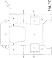
- FIG 12 a further alternative of the blank 34 illustrated in Figure 8 is illustrated which differs from the blank 34 illustrated in Figure 8 for the rounded shape of the connection tabs 36.
- the side walls 15 of collar 13 are higher than the upper wall 16 of the collar 13 along the vertical direction of the prevailing development of the pack 1 (i.e. the upper wall 16 of the collar 13 is arranged lower than the upper edge of the side walls 15 of the collar 13); in this embodiment, the inner wrap 4 can have the same height as the side walls 15 of the collar 13 (in this case the inner wrap 4 comes out from the pull-out opening 18 reaching beyond the upper wall 16 of the collar 13) or the inner wrap 4 can have the same height as the upper wall 16 of the collar 13 (in this case the inner wrap 4 ends flush with the upper wall 16 of the collar 13, i.e. ends lower than the upper edge 15 of the side walls of the collar 13).
- the blank 34 which is similar to blank 34 illustrated in Figure 8 , is illustrated and is adapted to form the collar 13 illustrated in Figure 13 .
- the inner wrap 4 is less deep than the container 2 (i.e. the depth of the inner wrap 4 is less than the depth of the container 2) and the collar 13 has a support element 37 (better illustrated in Figure 16 ), which raises (protrudes) from the rear wall 17 of the collar 13 and rests against the inner wrap 4 (in particular against the rear wall of the inner wrap 4) to help keep the inner wrap 4 in the correct position.
- the support element 37 protrudes towards the inside of the rear wall 17 of the collar 13 and touches the rear wall of the inner wrap 4.
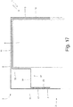
- the support element 37 is, in its cross sectional view "L"-shaped (clearly visible in Figure 17 ) and comprises a panel 38 which originates from the upper wall 16 of the collar 13, is arranged perpendicular to the upper wall 16 of the collar 13 and is arranged parallel to the rear wall 17 of the collar 13, and a panel 39 which originates from the rear wall 17 of the collar 13, is arranged perpendicular to the rear wall 17 of the collar 13 and is arranged parallel to the upper wall 16 of the collar 13; therefore the panel 38 is connected on one side to the upper wall 16 of the collar 13 and, on the opposite side, to the panel 39, whereas the panel 39 is connected on one side to the rear wall 17 of the collar 13 and on the opposite side to the panel 38.
- the collar 13 further comprises two support elements 40, each of which raises (protrudes) from a corresponding side wall 15 of the collar 13 and rests against the inner wrap 4 to help keep the inner wrap 4 in the correct position.
- the two support elements 40 protrude inwardly from the side walls 15 of the collar 13 and touch the rear wall of the inner wrap 4.
- Each support element 40 is made up of one single panel 41 which is hinged on one side to a corresponding side wall 15 and is folded by 90° relative to the side wall 15 itself.
- the rear wall 17 of the collar 13 may be glued by means of the glue 42 to the wall 7 of the container 2 to make the collar 13 more rigid in the area of the support element 37 (obviously the rear wall 17 of the collar 13 can never be glued to the rear wall 11 of the lid 2 otherwise it would be impossible to open the lid 2).
- FIG 18 the blank 34, which is similar to the blank 34 illustrated in Figure 8 , is illustrated and is adapted to form the collar 13 illustrated in Figures 15 , 16 and 17 ; note the panels 38 and 39 interposed between the panel 16', which forms the upper wall 16 of the collar 13, and the panel 17', which forms the rear wall 17 of the collar 13.
- the pull-out opening 18 is defined by a closed shape through incision which is formed through the collar 13 and internally delimits a throwaway portion of the collar 13 which is eliminated before folding the collar 13 around the inner wrap 4; in other words, the part of the collar 13 delimited by the closed shape through incision is separated and eliminated from the remaining part of the collar 13 (thus creating the pull-out opening 18) before folding the collar 13 around the inner wrap 4.
- the through incision which defines the pull-out opening 18 has an open "U"-shape, and therefore the collar 13 comprises an inner panel 43 which reproduces the shape of the pull-out opening 18 (since the pull-out opening 18 is obtained by separating the inner panel 43 from the remaining part of the collar 13), always remains connected to the remaining part of the collar 13 and is connected to the remaining part of the collar 13 along a folding line 44 (i.e. a pre-weakened folding line); in this way, the inner panel 43 of the collar 13 is moved away from the walls 14 and 16 of the collar 13, thus releasing (opening) the pull-out opening 18.
- a folding line 44 i.e. a pre-weakened folding line
- the inner panel 43 is folded around the folding line 44 and rests against the rear wall 17 of the collar 13: in the embodiment illustrated in Figure 19 , the inner panel 43 is folded by 90° around the folding line 44 and rests against the rear wall 17 of the collar 13 in front of the rear wall 17 itself (i.e. the inner panel 43 is located between the rear wall 17 and the inner wrap 4); alternatively, the inner panel 43 is folded by 180° around the folding line 44 and rests against the rear wall 17 of the collar 13 behind the rear wall 17 itself (i.e. the inner panel 43 is located between the rear wall 17 of the collar 13, on one side, and the rear wall 11 of the lid 3 and the rear wall 7 of the container 2 on the other side).
- Figure 20 the blank 34, which is similar to blank 34 illustrated in Figure 8 , is illustrated and is adapted to form the collar 13 illustrated in Figure 19 ; note the inner panel 43 which is separated from the remaining part of the collar 13 by an open "U"-shaped through incision and is connected to the panel 17' which forms the rear wall 17 of the collar 13 along the folding line 44.
- the inner wrap 4 is less deep than the container 2 (i.e. the depth of the inner wrap 4 is less than the depth of the container 2) and the collar 13 has the support element 37, which is formed by folding into a "Z" the inner panel 43, raises (protrudes) from the rear wall 17 of the collar 13 and rests against the inner wrap 4 (in particular against the rear wall of the inner wrap 4) to help keep the inner wrap 4 in the correct position.
- the inner panel 43 is divided into a portion 43' which is connected to the upper wall 16 of the collar 13 along the folding line 44, is arranged perpendicular to the upper wall 16 of the collar 13 and is arranged parallel to the rear wall 17 of the collar 13, in a portion 43" which is connected to the portion 43', is arranged perpendicular to the portion 43' and is arranged perpendicular to the rear wall 17 of the collar 13, and in a portion 43"' which is connected to the portion 43", is arranged perpendicular to the portion 43" and is arranged parallel to (and rests on) the rear wall 17 of the collar 13.
- the portion 43" of the inner panel 43 may be glued to the rear wall 17 of the collar 13 by means of the glue 45 and/or may be glued to the rear wall 7 of the container 2 by means of the glue 46 (in this way the collar 13, in the area of the support element 37, is made more rigid); obviously the portion 43" of the inner panel 43 can never be glued to the rear wall 11 of the lid 2 otherwise it would be impossible to open the lid 2 itself.
- the blank 34 is illustrated which is similar to the blank 34 illustrated in Figure 9 , and is adapted to form the collar 13 illustrated in Figure 21 ; note the inner panel 43 which is separated from the remaining part of the collar 13 by an open "U"-shaped through incision, is connected to the panel 16' which forms the upper wall 16 of the collar 13 along the folding line 44, and is divided into the three portions 43', 43" and 43"' by means of corresponding folding lines parallel to the folding line 44.
- the inner wrap 4 is arranged symmetrical (i.e. centered) relative to the side walls 8 of the container 2, therefore the side walls of the inner wrap 4 are equidistant from the corresponding side walls 8 of the container 2.
- the inner wrap 4 is arranged asymmetrical (i.e. not centered) relative to the side walls 8 of the container 2, therefore the side walls of the inner wrap 4 are not equidistant from the corresponding side walls 8 of the container 2; in this embodiment a support element 25 is wider than the other support element 25 or a single support element 25 is provided (therefore, from the opposite side, the inner wrap 4 is arranged in contact with the corresponding side wall 8 of the container 2).
- the inner wrap 4 has the same depth of the container 2 and the same width of the container 2 (therefore the collar 13 is devoid of the support elements 25, 37 and 40); in this case, it is not necessary to provide any special containment to the inner wrap 4 as the inner wrap 4 has the same size of the container 2 and the presence of the upper wall 16 and of the rear wall 17 of the collar 13 is justified by the fact of allowing a greater stability to the collar 13 itself.
- the pack 1 of cigarettes described above has numerous advantages.
- the pack 1 of cigarettes described above ensures in all conditions an adequate restraint of the inner wrap 4 (i.e. it is always able to effectively prevent the inner wrap 4 from " shaking " inside the container 2); said result is obtained thanks to the fact that the collar 13 has the upper wall 16 and the rear wall 17 which give to the collar 13 a greater rigidity and thus allow a better containment of the inner wrap 4.
- the presence of the pull-out opening 18 allows to pull-out the cigarettes contained inside the inner wrap 4 even in the presence of the upper wall 16.
- the pack 1 of cigarettes described above uses a relatively modest amount of wrapping material (i.e. only slightly higher than the amount of wrapping material used in a standard type rigid pack with a hinged lid).
- the pack 1 of cigarettes described above also has a great aesthetic impact at the opening of the lid 3, since the upper wall 16 of the collar 13 by upwardly closing the spaces not occupied by the inner wrap 4 (otherwise visible) transmit to the consumer a feeling of "completeness” and " solidity " that are particularly appreciated.
- the upper wall 16 of the collar 13 can also be printed with trademarks, designs or writings (due to its very visible position, the upper wall 16 of the collar 13 allows to optimally enhance the printing provided on the upper wall 16 itself).
- the pack 1 of cigarettes described above can be made in a fast and inexpensive manner, since both the blank 34 and the collar 13 have a relatively conventional shape (i.e. similar to the blanks known and normally used to make the collars of a rigid pack of cigarettes with a hinged lid currently on the market); in this context, it is important to note that the blank used to make the container 2 and the lid 3 is entirely conventional (i.e. identical to the blanks known and normally used to make a rigid pack of cigarettes with a hinged lid currently on the market).
- the shape of said pack 1 of cigarettes can be integrally destined also for making a packet of other types of smoking articles (such as cigars, cigarettes, electronic charging cartridges for electronic cigarettes, pieces of tobacco for electronic cigarettes).
Landscapes
- Engineering & Computer Science (AREA)
- Mechanical Engineering (AREA)
- Packaging Of Annular Or Rod-Shaped Articles, Wearing Apparel, Cassettes, Or The Like (AREA)
- Cartons (AREA)
- Cosmetics (AREA)
Abstract
Description
- The present invention relates to a rigid pack for tobacco articles.
- In particular, the present invention relates to a rigid pack for tobacco articles with a hinged lid and internally provided with a collar having an upper wall and a rear wall.
The present invention finds advantageous application to a pack of cigarettes containing a group of small-sized cigarettes, to which the following description will make explicit reference without implying any loss of generality - The patent applications
EP2311632-A1 ,EP0443365-A2 ,EP0801011-A1 andEP2666736-A1 describe a rigid pack of cigarettes with a hinged lid which is internally provided with a collar and has been modified to house a group of small-sized cigarettes, namely a group of cigarettes smaller than the total inner volume. - In the patent application
EP2311632-A1 the collar is of a standard type whereas the container is provided with containment elements that protrude inwards to rest against the group of cigarettes in order to prevent the group of cigarettes from "shaking" inside the pack of cigarettes. In the patent applicationsEP0443365-A2 ,EP0801011-A1 andEP2666736-A1 the container is of a standard type and the collar is provided with containment elements that protrude inwards to rest against the group of cigarettes in order to prevent the group of cigarettes from "shaking" inside the pack of cigarettes. - In fact, if the group of cigarettes were free to "shake" inside the pack of cigarettes, the movement of the group of cigarettes during handling of the pack of cigarettes (both in the production step, and during the distribution and selling step) would subject the cigarettes to mechanical stress that could easily cause an emptying of the tips (i.e. loss of tobacco fibers from the free ends of the cigarettes).
- However, these known technical solutions have some drawbacks in that they are not always able to provide adequate restraint of the group of cigarettes (i.e. are not always able to effectively prevent the group of cigarettes from "shaking" inside the pack of cigarettes).
- Finally, the document
WO2015067999-A1 illustrates a pack of cigarettes provided with a collar which is suitably folded so as to act as a filler for wrapping for small-sized or reduced number cigarettes. The collar is provided with upper walls that are arranged at a different height than the height of the upper wall of the inner wrap of the group of cigarettes; in particular, the upper surface of the collar is lower than the upper surface of the group of cigarettes, so as to ensure ease of extraction of the cigarettes. Said filler collar is, however, not very stable since being devoid of a rear wall, i.e. it surrounds the wrapped group of cigarettes only on three of its five free sides that come out from the pull-out opening of the container body. Furthermore, in the packaging step it is necessary to apply glue points to keep the panels that make up the upper walls of the collar connected and this operation is not always perfect, due to the high production speed of the machines for packaging packs of cigarettes, which often results in the staggered overlapping of said panels. - The object of the present invention is to provide a rigid pack for tobacco articles with a hinged lid and internally provided with a collar which is free from the drawbacks described above and, in particular, is simple and inexpensive to produce. According to the present invention a rigid pack for tobacco articles is provided, as claimed in the attached claims.
- The present invention will now be described with reference to the accompanying drawings, which illustrate some examples of non-limiting embodiments, wherein:
-
Figure 1 is a front perspective view and in a closed configuration of a pack of cigarettes according to the present invention; -
Figure 2 is a rear perspective view and in a closed configuration of the pack of cigarettes ofFigure 1 ; -
Figure 3 is a front perspective view and in an open configuration of the pack of cigarettes ofFigure 1 ; -
Figure 4 is a cross-sectional view of the pack of cigarettes ofFigure 1 ; -
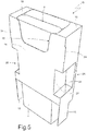
Figure 5 is a front perspective view of a collar of the pack of cigarettes ofFigure 1 coupled to an inner wrap; -
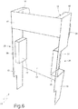
Figure 6 is a rear perspective view of only the collar ofFigure 5 ; -
Figure 7 is a plan view of a blank used to make a container and a lid of the pack of cigarettes ofFigure 1 ; -
Figure 8 is a plan view of a blank used to make the collar ofFigure 5 ; -
Figures 9 is a plan view of an alternative of the blank ofFigure 8 ; -
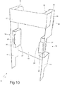
Figure 10 is a rear perspective view of an alternative of the collar ofFigure 5 ; -
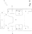
Figure 11 is a plan view of a blank used to make the collar ofFigure 10 ; -
Figure 12 is a plan view of a further alternative of the blank ofFigure 8 ; -
Figure 13 is a rear perspective view of a different embodiment of the collar ofFigure 5 ; -
Figure 14 is a plan view of a blank used to make the collar ofFigure 13 ; -
Figure 15 is a front perspective view of a further embodiment of the collar ofFigure 5 ; -
Figure 16 is a rear and partial perspective view of the collar ofFigure 15 ; -
Figure 17 is a schematic view and in cross section of an upper part of the collar ofFigure 15 ; -
Figure 18 is a plan view of a blank used to make the collar ofFigure 15 ; -
Figure 19 is a rear perspective view of a further embodiment of the collar ofFigure 5 ; -
Figure 20 is a plan view of a blank used to make the collar ofFigure 19 ; -
Figure 21 is a schematic view and in cross section of an upper part of an alternative of the collar ofFigure 19 ; and -
Figure 22 is a plan view of a blank used to make the collar ofFigure 21 . - In
Figures 1, 2 and3 number 1 denotes as a whole a rigid pack of cigarettes. - The
pack 1 of cigarettes comprises a parallelepipedshaped container 2, a parallelepipedshaped lid 3 which is hinged to the rear part of thecontainer 2 for rotating between a closed position (illustrated inFigures 1 and 2 ) and an open position (illustrated inFigure 3 ), and an inner wrap 4 (partially illustrated inFigure 3 ) which encloses a group of cigarettes and is housed inside thecontainer 2. Normally (but not obligatorily), theinner wrap 4 is formed by the group of cigarettes wrapped in a wrapping sheet of metalized paper which is provided with a tear-off upper portion removable at the first opening of thepack 1 of cigarettes; alternatively, theinner wrap 4 may be formed by the group of cigarettes wrapped in a wrapping sheet of waterproof and heat-sealable plastic material which is provided with a pull-out opening covered by a repositionable closing label (i.e. usable several times). - In the following description of the
pack 1 of cigarettes, terms such as "bottom" and "top" and "front" and "rear" will be used to designate the positions of portions of thepack 1 of cigarettes, assuming that thepack 1 is located in an arrangement such that the direction of its prevailing development coincides with the vertical direction; therefore, the lower and upper walls are arranged "at the bottom" and "at the top", respectively, and the front (or face) and rear walls define the "the front" and "the rear", respectively. - The term "cross section" means a section of the
pack 1 or of theinner wrap 4 obtained perpendicularly to its prevailing development direction. - The term "width" means a dimension measured parallel to the front wall and perpendicular to the side walls and to the prevailing development direction of the
pack 1. - The term "height" means a dimension measured parallel to the front wall and to the prevailing development direction of the
pack 1, and perpendicular to the lower and upper walls.
The term "depth" means a dimension measured perpendicular to the front wall and to the prevailing development direction of thepack 1, and parallel to the side walls. - The
container 2 is cup-shaped, has a parallelepiped shape and has an open upper end, alower wall 5 opposite to the open upper end, afront wall 6, a rear wall 7 (parallel and opposite to the front wall 6), and two side walls 8 (parallel and opposite to each other). In thecontainer 2, between the front andrear walls side walls 8 four longitudinal edges are defined, which are arranged parallel to the cigarettes of the group of cigarettes. In thecontainer 2, between thewalls lower wall 5 four transverse edges are defined, which are arranged perpendicular to the cigarettes of the group of cigarettes. - The
lid 3 is cup-shaped, has a parallelepiped shape and has an upper wall 9 (parallel and opposite to thelower wall 5 of thecontainer 2 when thelid 3 is arranged in the closed position), a front wall 10 (coplanar and adjacent to thefront wall 6 of thecontainer 2 when thelid 3 is arranged in the closed position), a rear wall 11 (hinged to therear wall 7 of thecontainer 2 and coplanar with therear wall 7 of thecontainer 2 when thelid 3 is arranged in the closed position), and two side walls 12 (coplanar and adjacent to thecorresponding side walls 8 of thecontainer 2 when thelid 3 is arranged in the closed position). In thelid 3, between the front andrear walls side walls 12 four longitudinal edges are defined, which are arranged parallel to the cigarettes of the group of cigarettes (when thelid 3 is arranged in the closed position). In thelid 3, between thewalls upper wall 9 four transverse edges are defined, which are arranged perpendicular to the cigarettes of the group of cigarettes (when thelid 3 is arranged in the closed position). - In the embodiments illustrated in the attached figures all the edges are straight; according to other embodiments not illustrated and perfectly equivalent part of the longitudinal and/or transverse edges may be bevelled or rounded.
- As well illustrated in
Figure 4 , theinner wrap 4 has a cross section (significantly) smaller than the cross section of thecontainer 2, and therefore in the container 2 a space of significant size (approximately 10-40% of the total volume of the container 2) remains unoccupied by theinner wrap 4. In particular, in the embodiment illustrated inFigure 4 theinner wrap 4 is narrower than the container 2 (i.e. the width of theinner wrap 4 is smaller than the inner width of the container 2); according to a different embodiment not illustrated, theinner wrap 4 may be (additionally or alternatively) shallower than the container 2 (i.e. the depth of theinner wrap 4 could be less than the depth of the container 2). - As illustrated in
Figures 3 ,5 and6 , thepack 1 of cigarettes comprises acollar 13 which embraces theinner wrap 4, is internally glued to thecontainer 2 and comes out of the upper open end of thecontainer 2. Thecollar 13 in cross section is substantially "U"-shaped and has afront wall 14 which is superimposed on and glued to thefront wall 6 of thecontainer 2 and twoside walls 15 that are folded by 90° relative to thefront wall 14 and are superimposed on and glued to theside walls 8 of thecontainer 2. In addition, thecollar 13 comprises anupper wall 16 which is arranged perpendicular to thefront wall 14 and to theside walls 15 and is parallel to and facing (and substantially in contact with) theupper wall 9 of thelid 3, when thelid 3 is in the closed position (illustrated inFigures 1 and 2 ). Finally, thecollar 13 comprises arear wall 17 which is perpendicular to theupper wall 16 and to theside walls 15, is parallel and opposite to thefront wall 6, and is superimposed on and glued to therear wall 7 of thecontainer 2; furthermore, therear wall 17 of thecollar 13 is parallel to and facing (and substantially in contact with) therear wall 11 of thelid 3, when thelid 3 is in the closed position (illustrated inFigures 1 and 2 ). Thefront wall 14 and therear wall 17 of thecollar 13 are in direct contact with (i.e. rest on) the front wall and the rear wall of theinner wrap 4, respectively, whereas theside walls 15 of thecollar 13 are arranged at a given distance from the side walls of theinner wrap 4 and touch the side walls of theinner wrap 4 by means of respective inner protrusions which will be better described hereinafter. - The
collar 13 has a pull-out opening for the cigarettes which is centrally arranged and extends on a portion of thefront wall 14 of thecollar 13 and on an upper portion of thewall 16 of thecollar 13. The pull-outopening 18 is defined by a through incision having a closed shape which is obtained through thecollar 13 and internally delimits a throwaway portion of thecollar 13 which is eliminated before folding thecollar 13 around theinner wrap 4. In the embodiment illustrated in the attached figures, the pull-outopening 18 extends on the entire depth of theupper wall 16 of thecollar 13 and therefore theupper wall 16 of thecollar 13 is physically present only at the two opposite sides of the pull-outopening 18; according to a different embodiment illustrated only inFigure 22 , the pull-outopening 18 does not extend on the entire depth of theupper wall 16 of thecollar 13 and therefore theupper wall 16 of thecollar 13 is physically present both at the two opposite sides of the pull-outopening 18, and in the back of the pull-out opening 18 (i.e. theupper wall 16 ofcollar 13 comprises a fixed frame which is "U"-shaped and surrounds an upper part of the pull-outopening 18 from three sides). - The
collar 13 has the function of keeping theinner wrap 4 in a correct position, i.e. to prevent theinner wrap 4 from performing unwanted movement inside the container 2 (since theinner wrap 4 is smaller than the container 2). Furthermore, thecollar 13 also has the function of keeping thelid 3 in the closed position with a certain force to avoid unwanted openings of thelid 3 itself; said function of "restraining" thelid 3 in the closed position is carried out thanks to the fact that when thelid 3 is in the closed position theinner collar 13 partially protrudes from the open end of thecontainer 2 and then engages a corresponding inner surface of lid 3: in this way to open thelid 3 it is necessary to elastically and slightly deform thelid 3 and/or thecollar 13 and is therefore necessary to apply a given force to thelid 3 in order to open thelid 3 itself. According to the embodiments illustrated inFigures 1-14 , thefront wall 14 of theinner container 3 is provided with a pair ofextensions 24 which laterally protrudes to engage with interference thelid 3 when thelid 3 is in the closed position so as to keep thelid 3 in the closed position with greater force. According to the different embodiment illustrated inFigures 15-18 , thefront wall 14 of theinner container 3 is devoid of theextensions 24. - In order to keep the
inner wrap 4 in a correct position, by compensating for the smaller width of theinner wrap 4 in respect to the inner width of thecontainer 2, thecollar 13 comprises a pair ofsupport elements 25, each of which raises (protrudes) from acorresponding side wall 15 of thecollar 13 and rests against theinner wrap 4 to help keep theinner wrap 4 in the correct position. Namely the twosupport elements 25 protrude inwardly from theside walls 15 of thecollar 13 and touch the side walls of theinner wrap 4. Eachsupport element 25 is, in its cross sectional view, "L"-shaped (clearly visible inFigure 4 ) and comprises apanel 26 which originates from acorresponding side wall 15 of thecollar 13 and is arranged perpendicular to theside wall 15 itself and apanel 27 which is joined to thepanel 26, originates from thefront wall 14 of thecollar 13, is arranged perpendicular to thefront wall 14 and rests on a corresponding side wall of theinner wrap 4. In the case in which the thickness of theinner wrap 4 is less than the thickness of thecontainer 2 and to keep theinner wrap 4 in a correct position by compensating for the riduced thickness of theinner wrap 4 compared to the thickness of thecontainer 2, to the inner wrap 4 a filler element may be coupled, which is interposed between a rear wall of theinner wrap 4 and therear wall 7 of thecontainer 2. - The
container 2 and thelid 3 are obtained by folding a blank 28 (illustrated inFigure 7 ) around theinner wrap 4 and the collar 13 (previously folded around to the inner wrap 4), which comprises a plurality of panels that will be marked with accented reference numbers equal to the reference numbers that distinguish the corresponding walls of thecontainer 2 and of thelid 3. As illustrated inFigure 7 , the blank 28 has two longitudinal folding lines 29 (which define the longitudinal edges of thecontainer 2 and of the lid 3) and a plurality oftransverse folding lines 30 which define, between the twolongitudinal folding lines 29, a panel 6' which forms thefront wall 6 of thecontainer 2, a panel 5' which forms thelower wall 5 of thecontainer 2 and is directly connected to the panel 6' along atransverse folding line 30, a panel 7' which forms therear wall 7 of thecontainer 2 and is directly connected to the panel 5' along atransverse folding line 30, a panel 11' which forms therear wall 11 of thelid 3 and is directly connected to the panel 7' along atransverse folding line 30, a panel 9' which forms theupper wall 9 of thelid 3 and is directly connected to the panel 11' along atransverse folding line 30, a panel 10' which forms thefront wall 10 of thelid 3 and is directly connected to the panel 9' along atransverse folding line 30. - The blank 28 comprises a
flap 31, which is connected to the panel 10' along atransverse folding line 30, is folded by 180° against the panel 10', and is internally glued to the panel 10' itself. - The blank 28 comprises a pair of wings 8', which are arranged on opposite sides of the panel 6', are connected to the panel 6' along the two
longitudinal folding lines 29, and form part ofside walls 8 of thecontainer 2. The blank 28 comprises a pair ofwings 8", which are arranged on opposite sides of the panel 7', are connected to the panel 7' along the twolongitudinal folding lines 29, form part ofside walls 8 of thecontainer 2, and are glued to and superimposed on the corresponding wings 8'. Eachwing 8" comprises atab 32 which is folded by 90° relative to thewing 8" and is superimposed on and glued to the panel 5' inside of thecontainer 2. - The blank 28 comprises a pair of wings 12', which are arranged on opposite sides of the panel 10', are connected to the panel 10' along the two
longitudinal folding lines 29, and form part of theside walls 12 of thelid 3. The blank 28 comprises a pair ofwings 12", which are arranged on opposite sides of the panel 11', are connected to the panel 11' along the twolongitudinal folding lines 29, form part of theside walls 12 of thelid 3, and are glued to and superimposed on the corresponding wings 12'. Eachwing 12" comprises atab 33 which is folded by 90° relative to thewing 12" and is superimposed on and glued to the panel 9' inside of thelid 3. - The
collar 13 is obtained by folding, around theinner wrap 4, a blank 34 (illustrated inFigure 8 ) comprising a plurality of panels that are marked with accented reference numbers equal to the reference numbers that distinguish the corresponding walls of thecollar 13. According to what is illustrated inFigure 8 , the blank 28 comprises a panel 14' which forms thefront wall 14 of thecollar 13, a panel 16' (divided into two opposite parts) which forms theupper wall 16 of thecollar 13 and is directly connected to the panel 14' along a transverse folding line, and a panel 17' which forms therear wall 17 of thecollar 13 and is directly connected to the panel 16' along a transverse folding line. The blank 34 comprises a pair of tabs 15', which are arranged on opposite sides of the panel 14', are connected to the panel 14' along two longitudinal folding lines, and form theside walls 15 of thecollar 13. - In the embodiment illustrated in
Figure 8 , the panel 16' (i.e. theupper wall 16 of the collar 13) comprises a pair ofconnection tabs 35, each of which is folded by 90° relative to the panel 16' (i.e. relative to theupper wall 16 of the collar 13) and is glued to an inner face of a corresponding wing 15' (i.e. of acorresponding side wall 15 of the collar 13). In the alternative illustrated inFigure 9 , theconnection tabs 35 are moved from the panel 16' (i.e. from theupper wall 16 of the collar 13) to the wings 15' (i.e. to theside walls 15 of the collar 13), therefore in this embodiment, each wing 15' (i.e. eachside wall 15 of the collar 13) comprises aconnection tab 35, which is folded by 90° relative to the wing 15' (i.e. to thecorresponding side wall 15 of the collar 13) and is glued to an inner face of the panel 16' (i.e. of theupper wall 16 of the collar 13). The function of theconnection tabs 35 is to establish a mechanical connection between theupper wall 16 of thecollar 13 and theside walls 15 of the collar 13 (which are glued to theside walls 8 of the container 2) so as to make theupper wall 16 of thecollar 13 more stable, and then, among other things, improve the containment of theinner wrap 4. - The panel 17' (i.e. the
rear wall 17 of the collar 13) comprises a pair ofconnection tabs 36, each of which is folded by 90° relative to the panel 17' (i.e. relative to therear wall 17 of the collar 13) and is glued to an inner face or to an outer face of a corresponding wing 15' (i.e. of acorresponding side wall 15 of the collar 13). The function of theconnection tabs 36 is to establish a mechanical connection between therear wall 17 of thecollar 13 and theside walls 15 of the collar 13 (which are glued to theside walls 8 of container 2) to make therear wall 17 of thecollar 13 more stable (and indirectly make theupper wall 16 of thecollar 13 more stable, which is directly connected to therear wall 17 of the collar 13) and therefore, among other things, improve the containment of theinner wrap 4. In other words, theconnection tabs 36 serve to stabilize therear wall 17 of thecollar 13, i.e. to make therear wall 17 of thecollar 13 more stable in its own position thus preventing therear wall 17 of thecollar 13 from performing (small) unwanted movement particularly during the rotation of thelid 3. Due to the presence of theconnection tabs 36 thelid 3 is prevented from jamming against thecollar 13 when thelid 3 is closed again after a complete 180° opening. Moreover, thanks to the presence of theconnection tabs 36 the keeping of thelid 3 in the closed position is improved. - In the alternative illustrated in
Figure 10 , eachpanel 27 has anappendage 28 protrudes from thepanel 27 itself, protruding from the plane defined by the correspondingpanel 26; theappendage 28 is obtained by means of a through incision, which is "U"-shaped and is made through the correspondingpanel 26. In the alternative illustrated inFigure 10 , theconnection tabs 36 are glued to an outer face of a corresponding wing 15' (i.e. of acorresponding side wall 15 of the collar 13) and are therefore visible from the outside (as illustrated inFigure 10 ). InFigure 11 the blank 34, which is similar to the blank 34 illustrated inFigure 9 , is illustrated, and is adapted to form thecollar 13 provided with theappendages 28 illustrated inFigure 11 . - In
Figure 12 a further alternative of the blank 34 illustrated inFigure 8 is illustrated which differs from the blank 34 illustrated inFigure 8 for the rounded shape of theconnection tabs 36. - In the embodiment illustrated in
Figure 13 , theside walls 15 ofcollar 13 are higher than theupper wall 16 of thecollar 13 along the vertical direction of the prevailing development of the pack 1 (i.e. theupper wall 16 of thecollar 13 is arranged lower than the upper edge of theside walls 15 of the collar 13); in this embodiment, theinner wrap 4 can have the same height as theside walls 15 of the collar 13 (in this case theinner wrap 4 comes out from the pull-outopening 18 reaching beyond theupper wall 16 of the collar 13) or theinner wrap 4 can have the same height as theupper wall 16 of the collar 13 (in this case theinner wrap 4 ends flush with theupper wall 16 of thecollar 13, i.e. ends lower than theupper edge 15 of the side walls of the collar 13). InFigure 14 the blank 34, which is similar to blank 34 illustrated inFigure 8 , is illustrated and is adapted to form thecollar 13 illustrated inFigure 13 . - In the embodiment illustrated in
Figures 15 ,16 and17 , theinner wrap 4 is less deep than the container 2 (i.e. the depth of theinner wrap 4 is less than the depth of the container 2) and thecollar 13 has a support element 37 (better illustrated inFigure 16 ), which raises (protrudes) from therear wall 17 of thecollar 13 and rests against the inner wrap 4 (in particular against the rear wall of the inner wrap 4) to help keep theinner wrap 4 in the correct position. Namely thesupport element 37 protrudes towards the inside of therear wall 17 of thecollar 13 and touches the rear wall of theinner wrap 4. Thesupport element 37 is, in its cross sectional view "L"-shaped (clearly visible inFigure 17 ) and comprises apanel 38 which originates from theupper wall 16 of thecollar 13, is arranged perpendicular to theupper wall 16 of thecollar 13 and is arranged parallel to therear wall 17 of thecollar 13, and apanel 39 which originates from therear wall 17 of thecollar 13, is arranged perpendicular to therear wall 17 of thecollar 13 and is arranged parallel to theupper wall 16 of thecollar 13; therefore thepanel 38 is connected on one side to theupper wall 16 of thecollar 13 and, on the opposite side, to thepanel 39, whereas thepanel 39 is connected on one side to therear wall 17 of thecollar 13 and on the opposite side to thepanel 38. According to the embodiment illustrated inFigure 15 , thecollar 13 further comprises twosupport elements 40, each of which raises (protrudes) from acorresponding side wall 15 of thecollar 13 and rests against theinner wrap 4 to help keep theinner wrap 4 in the correct position. Namely the twosupport elements 40 protrude inwardly from theside walls 15 of thecollar 13 and touch the rear wall of theinner wrap 4. Eachsupport element 40 is made up of onesingle panel 41 which is hinged on one side to acorresponding side wall 15 and is folded by 90° relative to theside wall 15 itself. According to a possible embodiment illustrated inFigure 17 , therear wall 17 of thecollar 13 may be glued by means of theglue 42 to thewall 7 of thecontainer 2 to make thecollar 13 more rigid in the area of the support element 37 (obviously therear wall 17 of thecollar 13 can never be glued to therear wall 11 of thelid 2 otherwise it would be impossible to open the lid 2). - In
Figure 18 the blank 34, which is similar to the blank 34 illustrated inFigure 8 , is illustrated and is adapted to form thecollar 13 illustrated inFigures 15 ,16 and17 ; note thepanels upper wall 16 of thecollar 13, and the panel 17', which forms therear wall 17 of thecollar 13. - In the embodiments illustrated in
Figures 1-18 , the pull-outopening 18 is defined by a closed shape through incision which is formed through thecollar 13 and internally delimits a throwaway portion of thecollar 13 which is eliminated before folding thecollar 13 around theinner wrap 4; in other words, the part of thecollar 13 delimited by the closed shape through incision is separated and eliminated from the remaining part of the collar 13 (thus creating the pull-out opening 18) before folding thecollar 13 around theinner wrap 4. - In the embodiment illustrated in
Figure 19 , the through incision which defines the pull-outopening 18 has an open "U"-shape, and therefore thecollar 13 comprises aninner panel 43 which reproduces the shape of the pull-out opening 18 (since the pull-outopening 18 is obtained by separating theinner panel 43 from the remaining part of the collar 13), always remains connected to the remaining part of thecollar 13 and is connected to the remaining part of thecollar 13 along a folding line 44 (i.e. a pre-weakened folding line); in this way, theinner panel 43 of thecollar 13 is moved away from thewalls collar 13, thus releasing (opening) the pull-outopening 18. Theinner panel 43 is folded around thefolding line 44 and rests against therear wall 17 of the collar 13: in the embodiment illustrated inFigure 19 , theinner panel 43 is folded by 90° around thefolding line 44 and rests against therear wall 17 of thecollar 13 in front of therear wall 17 itself (i.e. theinner panel 43 is located between therear wall 17 and the inner wrap 4); alternatively, theinner panel 43 is folded by 180° around thefolding line 44 and rests against therear wall 17 of thecollar 13 behind therear wall 17 itself (i.e. theinner panel 43 is located between therear wall 17 of thecollar 13, on one side, and therear wall 11 of thelid 3 and therear wall 7 of thecontainer 2 on the other side). - In
Figure 20 the blank 34, which is similar to blank 34 illustrated inFigure 8 , is illustrated and is adapted to form thecollar 13 illustrated inFigure 19 ; note theinner panel 43 which is separated from the remaining part of thecollar 13 by an open "U"-shaped through incision and is connected to the panel 17' which forms therear wall 17 of thecollar 13 along thefolding line 44. - In the alternative illustrated in
Figure 21 , theinner wrap 4 is less deep than the container 2 (i.e. the depth of theinner wrap 4 is less than the depth of the container 2) and thecollar 13 has thesupport element 37, which is formed by folding into a "Z" theinner panel 43, raises (protrudes) from therear wall 17 of thecollar 13 and rests against the inner wrap 4 (in particular against the rear wall of the inner wrap 4) to help keep theinner wrap 4 in the correct position. In particular, theinner panel 43 is divided into a portion 43' which is connected to theupper wall 16 of thecollar 13 along thefolding line 44, is arranged perpendicular to theupper wall 16 of thecollar 13 and is arranged parallel to therear wall 17 of thecollar 13, in aportion 43" which is connected to the portion 43', is arranged perpendicular to the portion 43' and is arranged perpendicular to therear wall 17 of thecollar 13, and in aportion 43"' which is connected to theportion 43", is arranged perpendicular to theportion 43" and is arranged parallel to (and rests on) therear wall 17 of thecollar 13. According to a possible embodiment, theportion 43" of theinner panel 43 may be glued to therear wall 17 of thecollar 13 by means of theglue 45 and/or may be glued to therear wall 7 of thecontainer 2 by means of the glue 46 (in this way thecollar 13, in the area of thesupport element 37, is made more rigid); obviously theportion 43" of theinner panel 43 can never be glued to therear wall 11 of thelid 2 otherwise it would be impossible to open thelid 2 itself. - In
Figure 22 the blank 34 is illustrated which is similar to the blank 34 illustrated inFigure 9 , and is adapted to form thecollar 13 illustrated inFigure 21 ; note theinner panel 43 which is separated from the remaining part of thecollar 13 by an open "U"-shaped through incision, is connected to the panel 16' which forms theupper wall 16 of thecollar 13 along thefolding line 44, and is divided into the threeportions 43', 43" and 43"' by means of corresponding folding lines parallel to thefolding line 44. - In the embodiments illustrated, the
inner wrap 4 is arranged symmetrical (i.e. centered) relative to theside walls 8 of thecontainer 2, therefore the side walls of theinner wrap 4 are equidistant from thecorresponding side walls 8 of thecontainer 2. According to a different and perfectly equivalent embodiment, not illustrated, theinner wrap 4 is arranged asymmetrical (i.e. not centered) relative to theside walls 8 of thecontainer 2, therefore the side walls of theinner wrap 4 are not equidistant from thecorresponding side walls 8 of thecontainer 2; in this embodiment asupport element 25 is wider than theother support element 25 or asingle support element 25 is provided (therefore, from the opposite side, theinner wrap 4 is arranged in contact with thecorresponding side wall 8 of the container 2). - According to a different embodiment not illustrated, the
inner wrap 4 has the same depth of thecontainer 2 and the same width of the container 2 (therefore thecollar 13 is devoid of thesupport elements inner wrap 4 as theinner wrap 4 has the same size of thecontainer 2 and the presence of theupper wall 16 and of therear wall 17 of thecollar 13 is justified by the fact of allowing a greater stability to thecollar 13 itself.
Thepack 1 of cigarettes described above has numerous advantages. - In the first place, the
pack 1 of cigarettes described above ensures in all conditions an adequate restraint of the inner wrap 4 (i.e. it is always able to effectively prevent theinner wrap 4 from "shaking" inside the container 2); said result is obtained thanks to the fact that thecollar 13 has theupper wall 16 and therear wall 17 which give to the collar 13 a greater rigidity and thus allow a better containment of theinner wrap 4. At the same time, the presence of the pull-outopening 18 allows to pull-out the cigarettes contained inside theinner wrap 4 even in the presence of theupper wall 16. - The
pack 1 of cigarettes described above uses a relatively modest amount of wrapping material (i.e. only slightly higher than the amount of wrapping material used in a standard type rigid pack with a hinged lid). - The
pack 1 of cigarettes described above also has a great aesthetic impact at the opening of thelid 3, since theupper wall 16 of thecollar 13 by upwardly closing the spaces not occupied by the inner wrap 4 (otherwise visible) transmit to the consumer a feeling of "completeness" and "solidity" that are particularly appreciated. Theupper wall 16 of thecollar 13 can also be printed with trademarks, designs or writings (due to its very visible position, theupper wall 16 of thecollar 13 allows to optimally enhance the printing provided on theupper wall 16 itself). - The
pack 1 of cigarettes described above can be made in a fast and inexpensive manner, since both the blank 34 and thecollar 13 have a relatively conventional shape (i.e. similar to the blanks known and normally used to make the collars of a rigid pack of cigarettes with a hinged lid currently on the market); in this context, it is important to note that the blank used to make thecontainer 2 and thelid 3 is entirely conventional (i.e. identical to the blanks known and normally used to make a rigid pack of cigarettes with a hinged lid currently on the market). - Because of the many advantages presented by the
pack 1 of cigarettes described above, the shape of saidpack 1 of cigarettes can be integrally destined also for making a packet of other types of smoking articles (such as cigars, cigarettes, electronic charging cartridges for electronic cigarettes, pieces of tobacco for electronic cigarettes).
Claims (20)
- A rigid pack (1) for tobacco articles comprising:a container (2), which has a parallelepiped shape, has an open upper end, a lower wall (5), a front wall (6), a rear wall (7), and two side walls (8);a lid (3), which is hinged to the container (2), has a parallelepiped shape and has an upper wall (9), a front wall (10), a rear wall (11), and two side walls (12);an inner wrap (4) which encloses a group of tobacco articles, is housed on the inside of the container (2) and has a cross section that is smaller than the cross section of the container (2); anda collar (13), which embraces the inner wrap (4), is internally glued to the container (2), comes out of the open upper end of the container (2) and has a front wall (14), two side walls (15) and an upper wall (16) which is arranged perpendicular to the front wall (14);wherein the collar (13) comprises at least one support element (25; 37), which projects from a corresponding wall (15; 17) of the collar (13) and rests against the inner wrap (4) to help keep the inner wrap (4) in the correct position; andwherein the collar (13) comprises a pull-out opening (18) for the tobacco articles, which extends on a portion of the front wall (14) of the collar (13) and on a portion of the upper wall (16) of the collar (13);the pack (1) for tobacco articles is characterized in that the collar (13) comprises a rear wall (17) which is arranged perpendicular to the upper wall (16) is parallel and opposite to the front wall (14), and overlaps the rear wall (7) of the container (2);wherein the pull-out opening (18) is defined by an open "U"-shaped through incision; andwherein the collar (13) comprises an inner panel (43) which reproduces the shape of the pull-out opening (18) and is connected to the remaining part of the collar (13) along a folding line (44).
- The pack (1) for tobacco articles according to claim 1, wherein the rear wall (17) of the collar (13) laterally has a pair of first connection tabs (36), which are arranged on opposite sides of the rear wall (17), are folded by 90° relative to the rear wall (17), and are glued to the corresponding side walls (15) of the collar (13).
- The pack (1) for tobacco articles according to claim 1 or 2, wherein the upper wall (16) of the collar (13) comprises a pair of second connection tabs (35), each of which is hinged to the upper wall (16), is folded by 90° relative to the upper wall (16), and is glued to a corresponding side wall (15) of the collar (13).
- The pack (1) for tobacco articles according to claim 1 or 2, wherein each side wall (15) of the collar (13) comprises a second connection tab (35), which is hinged to the side wall (15), is folded by 90° relative to the side wall (15), and is glued to the upper wall (16) of the collar (13).
- The pack (1) for tobacco articles according to any of the claims from 1 to 4, wherein:the inner wrap (4) has a narrower cross section compared to the cross section of the container (2); andthe collar (13) comprises at least a first support element (25), which projects from a corresponding side wall (15) of the collar (13) and rests against the inner wrap (4) to help keep the inner wrap (4) in the correct position.
- The pack (1) for tobacco articles according to claim 5, wherein the first support element (25) is, in its cross sectional view, "L"-shaped and comprises a first panel (26) which originates from a corresponding side wall (15) of the collar (13) and is arranged perpendicular to the side wall (15), and a second panel (27), which is joined to the first panel (26), originates from the front wall (14) of the collar (13), is arranged perpendicular to the front wall (14) and rests against a corresponding side wall of the inner wrap (4).
- The pack (1) for tobacco articles according to claim 6, wherein:the second panel (27) has an appendage (28) that projects from the second panel (27), thus extending out of the plane defined by the corresponding first panel (26); andthe appendage (28) is obtained by means of a through incision, which is "U"-shaped and is made through the corresponding first panel (26).
- The pack (1) for tobacco articles according to any one of the claims from 1 to 4, wherein:the inner wrap (4) has a less deep cross section compared to the cross section of the container (2); andthe collar (13) comprises at least one second support element (37), which projects from the rear wall (17) of the collar (13) and rests against the inner wrap (4) to help keep the inner wrap (4) in the correct position.
- The pack (1) for tobacco articles according to claim 8, wherein the second support element (37), is, in its cross-sectional view "L"-shaped and comprises:a third panel (38) which originates from the upper wall (16) of the collar (13), is arranged perpendicular to the upper wall (16) of the collar (13), is arranged parallel to the rear wall (17) of the collar (13), and rests against a rear wall of the inner wrap (4); anda fourth panel (39) which originates from the rear wall (17) of the collar (13), is arranged perpendicular to the rear wall (17) of the collar (13), is arranged parallel to the upper wall (16) of the collar (13), and is connected to the third panel (38).
- The pack (1) for tobacco articles according to claim 8 or 9, wherein the collar (13) comprises two third support elements (40), each of which projects from a corresponding side wall (15) of the collar (13) and rests against the inner wrap (4) to help keep the inner wrap (4) in the correct position.
- The pack (1) for tobacco articles according to claim 10, wherein each third support element (40) is made up of one single panel (41), which is hinged on one side to a corresponding side wall (15) and is folded by 90° relative to the side wall (15).
- The pack (1) for tobacco articles according to any one of the claims from 1 to 11, wherein the side walls (15) of the collar (13) are higher than the upper wall (16) of the collar (13).
- The pack (1) for tobacco articles according to claim 12, wherein the inner wrap (4) has the same height as the side walls (15) of the collar (13) and projects from the pull-out opening (18) protruding beyond the upper wall (16) of the collar (13).
- The pack (1) for tobacco articles according to claim 12, wherein the inner wrap (4) has the same height as the upper wall (16) of the collar (13) and ends flush with the upper wall (16) of the collar (13).
- The pack (1) for tobacco articles according to any one of the claims from 1 to 14, wherein the inner wrap (4) has a smaller thickness compared to the thickness of the container (2) and a filler element is provided, which is interposed between a rear wall of the inner wrap (4) and the rear wall (7) of the container (2), to help keep the inner wrap (4) in the correct position.
- The pack (1) for tobacco articles according to any one of the claims from 1 to 15, wherein the inner panel (43) is connected to the rear wall (17) of the collar (13) along the folding line (44), and is folded against the rear wall (17) of the collar (13) around the folding line (44).
- The pack (1) for tobacco articles according to any one of the claims from 1 to 15, wherein the inner panel (43) is connected to the upper wall (16) of the collar (13) along a folding line (44), and is folded around the folding line (44).
- The pack (1) for tobacco articles according to claim 17, wherein the inner wrap (4) has a less deep cross section compared to the cross section of the container (2); and
the collar (13) comprises at least one second support element (37), which projects from the rear wall (17) of the collar (13), rests against the inner wrap (4) to help keep the inner wrap (4) in the correct position, and is made up of the inner panel (43), which is properly folded. - The pack (1) for tobacco articles according to claim 18, wherein the inner panel (43) comprises:a first portion (43') which is connected to the upper wall (16) of the collar (13) along the folding line (44), is arranged perpendicular to the upper wall (16) of the collar (13) and is arranged parallel to the rear wall (17) of the collar (13);a second portion (43") which is connected to the first portion (43'), is arranged perpendicular to the first portion (43') and is arranged perpendicular to the rear wall (17) of the collar (13); anda third portion (43"') which is connected to the second portion (43"), is arranged perpendicular to the second portion (43") and is arranged parallel to the rear wall (17) of the collar (13).
- The pack (1) for tobacco articles according to claim 19, wherein the third portion (43"') of the inner panel (43) is glued to the rear wall (17) of the collar (13) and/or is glued to rear wall (7) of the container (2).
Priority Applications (1)
| Application Number | Priority Date | Filing Date | Title |
|---|---|---|---|
| PL16203679T PL3181482T3 (en) | 2015-12-18 | 2016-12-13 | Rigid pack for tobacco articles |
Applications Claiming Priority (1)
| Application Number | Priority Date | Filing Date | Title |
|---|---|---|---|
| ITUB2015A009315A ITUB20159315A1 (en) | 2015-12-18 | 2015-12-18 | Rigid package of smoking items. |
Publications (2)
| Publication Number | Publication Date |
|---|---|
| EP3181482A1 true EP3181482A1 (en) | 2017-06-21 |
| EP3181482B1 EP3181482B1 (en) | 2018-10-24 |
Family
ID=55697350
Family Applications (1)
| Application Number | Title | Priority Date | Filing Date |
|---|---|---|---|
| EP16203679.2A Active EP3181482B1 (en) | 2015-12-18 | 2016-12-13 | Rigid pack for tobacco articles |
Country Status (4)
| Country | Link |
|---|---|
| EP (1) | EP3181482B1 (en) |
| ES (1) | ES2693600T3 (en) |
| IT (1) | ITUB20159315A1 (en) |
| PL (1) | PL3181482T3 (en) |
Cited By (2)
| Publication number | Priority date | Publication date | Assignee | Title |
|---|---|---|---|---|
| WO2019173119A1 (en) | 2018-03-06 | 2019-09-12 | Altria Client Services Llc | Re-sealable cigarette pack |
| CN112074469A (en) * | 2018-04-03 | 2020-12-11 | 佛克有限及两合公司 | Pack for products of the cigarette industry and method for producing a pack for products of the cigarette industry |
Citations (5)
| Publication number | Priority date | Publication date | Assignee | Title |
|---|---|---|---|---|
| US4850482A (en) * | 1988-06-10 | 1989-07-25 | Philip Morris Incorporated | Cigarette box innerframe |
| EP2277786A1 (en) * | 2009-07-17 | 2011-01-26 | JT International S.A. | Cigarette pack construction |
| WO2015067999A1 (en) * | 2013-11-08 | 2015-05-14 | Gima Tt S.R.L. | Rigid container with hinged lid |
| WO2015114585A1 (en) * | 2014-01-31 | 2015-08-06 | G.D Societa' Per Azioni | A rigid packet of smoking articles with inner volume divided into two distinct chambers |
| WO2015114561A1 (en) * | 2014-01-31 | 2015-08-06 | G.D S.P.A. | Packet for tobacco products |
-
2015
- 2015-12-18 IT ITUB2015A009315A patent/ITUB20159315A1/en unknown
-
2016
- 2016-12-13 EP EP16203679.2A patent/EP3181482B1/en active Active
- 2016-12-13 ES ES16203679.2T patent/ES2693600T3/en active Active
- 2016-12-13 PL PL16203679T patent/PL3181482T3/en unknown
Patent Citations (5)
| Publication number | Priority date | Publication date | Assignee | Title |
|---|---|---|---|---|
| US4850482A (en) * | 1988-06-10 | 1989-07-25 | Philip Morris Incorporated | Cigarette box innerframe |
| EP2277786A1 (en) * | 2009-07-17 | 2011-01-26 | JT International S.A. | Cigarette pack construction |
| WO2015067999A1 (en) * | 2013-11-08 | 2015-05-14 | Gima Tt S.R.L. | Rigid container with hinged lid |
| WO2015114585A1 (en) * | 2014-01-31 | 2015-08-06 | G.D Societa' Per Azioni | A rigid packet of smoking articles with inner volume divided into two distinct chambers |
| WO2015114561A1 (en) * | 2014-01-31 | 2015-08-06 | G.D S.P.A. | Packet for tobacco products |
Cited By (9)
| Publication number | Priority date | Publication date | Assignee | Title |
|---|---|---|---|---|
| WO2019173119A1 (en) | 2018-03-06 | 2019-09-12 | Altria Client Services Llc | Re-sealable cigarette pack |
| EP3762311A4 (en) * | 2018-03-06 | 2021-05-19 | Altria Client Services LLC | CLOSABLE CIGARETTE PACKAGE |
| US11434066B2 (en) | 2018-03-06 | 2022-09-06 | Altria Client Services Llc | Re-sealable cigarette pack |
| US11708212B2 (en) | 2018-03-06 | 2023-07-25 | Altria Client Services Llc | Re-sealable cigarette pack |
| US12060217B2 (en) | 2018-03-06 | 2024-08-13 | Altria Client Services Llc | Re-sealable cigarette pack |
| EP4467477A3 (en) * | 2018-03-06 | 2025-02-26 | Altria Client Services LLC | Re-sealable cigarette pack |
| US12319489B2 (en) | 2018-03-06 | 2025-06-03 | Altria Client Services Llc | Re-sealable cigarette pack |
| CN112074469A (en) * | 2018-04-03 | 2020-12-11 | 佛克有限及两合公司 | Pack for products of the cigarette industry and method for producing a pack for products of the cigarette industry |
| CN112074469B (en) * | 2018-04-03 | 2022-11-29 | 佛克有限及两合公司 | Packaging for products used in the cigarette industry |
Also Published As
| Publication number | Publication date |
|---|---|
| PL3181482T3 (en) | 2019-03-29 |
| ES2693600T3 (en) | 2018-12-12 |
| EP3181482B1 (en) | 2018-10-24 |
| ITUB20159315A1 (en) | 2017-06-18 |
Similar Documents
| Publication | Publication Date | Title |
|---|---|---|
| EP3250479B1 (en) | Rigid pack with hinged lid and internally provided with a collar having an upper wall | |
| EP1502864B1 (en) | Rigid hinged-lid package of tobacco articles and relative blank | |
| EP3227195B1 (en) | Rigid packet with hinged lid and containing a group of smoking articles of reduced size | |
| US8511462B2 (en) | Multi-product packet | |
| EP2840044A1 (en) | Hinged-lid, slide-open package of tobacco articles | |
| US7832556B2 (en) | Package for small groups of tobacco articles | |
| CN106458430B (en) | Packaging for smoking product | |
| CN102470974B (en) | Boxes and corresponding blanks for smoking articles | |
| CN107000923B (en) | Package containing access opening with closure flap | |
| EP3181482B1 (en) | Rigid pack for tobacco articles | |
| US8136662B2 (en) | Hinge-lid container with additional spacer panel | |
| WO2013144921A1 (en) | Rigid swing-open package of tobacco articles | |
| JP2007535449A (en) | Strong hinged lid package for tobacco products | |
| EP3227196B1 (en) | Rigid packet with hinged lid and containing a group of smoking articles of reduced size | |
| EA034836B1 (en) | Pack for consumer goods, packaging blank and method for folding a pack for consumer goods | |
| EP4490072B1 (en) | Rigid package of smoking articles | |
| CN105073604A (en) | Rigid, hinged-lid, slide-open packet of cigarettes | |
| EP3197795B1 (en) | Packet of smoking articles with laterally hinged lid | |
| JP3161821U (en) | Packaging box | |
| EP2546158A1 (en) | Container for consumer goods formed of a single laminar blank |
Legal Events
| Date | Code | Title | Description |
|---|---|---|---|
| PUAI | Public reference made under article 153(3) epc to a published international application that has entered the european phase |
Free format text: ORIGINAL CODE: 0009012 |
|
| AK | Designated contracting states |
Kind code of ref document: A1 Designated state(s): AL AT BE BG CH CY CZ DE DK EE ES FI FR GB GR HR HU IE IS IT LI LT LU LV MC MK MT NL NO PL PT RO RS SE SI SK SM TR |
|
| AX | Request for extension of the european patent |
Extension state: BA ME |
|
| 17P | Request for examination filed |
Effective date: 20171220 |
|
| RBV | Designated contracting states (corrected) |
Designated state(s): AL AT BE BG CH CY CZ DE DK EE ES FI FR GB GR HR HU IE IS IT LI LT LU LV MC MK MT NL NO PL PT RO RS SE SI SK SM TR |
|
| RIC1 | Information provided on ipc code assigned before grant |
Ipc: B65D 85/10 20060101AFI20180314BHEP |
|
| GRAP | Despatch of communication of intention to grant a patent |
Free format text: ORIGINAL CODE: EPIDOSNIGR1 |
|
| INTG | Intention to grant announced |
Effective date: 20180503 |
|
| GRAS | Grant fee paid |
Free format text: ORIGINAL CODE: EPIDOSNIGR3 |
|
| GRAA | (expected) grant |
Free format text: ORIGINAL CODE: 0009210 |
|
| AK | Designated contracting states |
Kind code of ref document: B1 Designated state(s): AL AT BE BG CH CY CZ DE DK EE ES FI FR GB GR HR HU IE IS IT LI LT LU LV MC MK MT NL NO PL PT RO RS SE SI SK SM TR |
|
| REG | Reference to a national code |
Ref country code: CH Ref legal event code: EP |
|
| REG | Reference to a national code |
Ref country code: RO Ref legal event code: EPE Ref country code: IE Ref legal event code: FG4D |
|
| REG | Reference to a national code |
Ref country code: CH Ref legal event code: NV Representative=s name: HEPP WENGER RYFFEL AG, CH Ref country code: AT Ref legal event code: REF Ref document number: 1056412 Country of ref document: AT Kind code of ref document: T Effective date: 20181115 |
|
| REG | Reference to a national code |
Ref country code: DE Ref legal event code: R096 Ref document number: 602016006641 Country of ref document: DE |
|
| REG | Reference to a national code |
Ref country code: ES Ref legal event code: FG2A Ref document number: 2693600 Country of ref document: ES Kind code of ref document: T3 Effective date: 20181212 |
|
| PGFP | Annual fee paid to national office [announced via postgrant information from national office to epo] |
Ref country code: RO Payment date: 20181113 Year of fee payment: 3 |
|
| REG | Reference to a national code |
Ref country code: NL Ref legal event code: MP Effective date: 20181024 |
|
| PGFP | Annual fee paid to national office [announced via postgrant information from national office to epo] |
Ref country code: FR Payment date: 20181226 Year of fee payment: 3 |
|
| REG | Reference to a national code |
Ref country code: LT Ref legal event code: MG4D |
|
| REG | Reference to a national code |
Ref country code: AT Ref legal event code: MK05 Ref document number: 1056412 Country of ref document: AT Kind code of ref document: T Effective date: 20181024 |
|
| PG25 | Lapsed in a contracting state [announced via postgrant information from national office to epo] |
Ref country code: NL Free format text: LAPSE BECAUSE OF FAILURE TO SUBMIT A TRANSLATION OF THE DESCRIPTION OR TO PAY THE FEE WITHIN THE PRESCRIBED TIME-LIMIT Effective date: 20181024 |
|
| PG25 | Lapsed in a contracting state [announced via postgrant information from national office to epo] |
Ref country code: AT Free format text: LAPSE BECAUSE OF FAILURE TO SUBMIT A TRANSLATION OF THE DESCRIPTION OR TO PAY THE FEE WITHIN THE PRESCRIBED TIME-LIMIT Effective date: 20181024 Ref country code: LT Free format text: LAPSE BECAUSE OF FAILURE TO SUBMIT A TRANSLATION OF THE DESCRIPTION OR TO PAY THE FEE WITHIN THE PRESCRIBED TIME-LIMIT Effective date: 20181024 Ref country code: IS Free format text: LAPSE BECAUSE OF FAILURE TO SUBMIT A TRANSLATION OF THE DESCRIPTION OR TO PAY THE FEE WITHIN THE PRESCRIBED TIME-LIMIT Effective date: 20190224 Ref country code: NO Free format text: LAPSE BECAUSE OF FAILURE TO SUBMIT A TRANSLATION OF THE DESCRIPTION OR TO PAY THE FEE WITHIN THE PRESCRIBED TIME-LIMIT Effective date: 20190124 Ref country code: FI Free format text: LAPSE BECAUSE OF FAILURE TO SUBMIT A TRANSLATION OF THE DESCRIPTION OR TO PAY THE FEE WITHIN THE PRESCRIBED TIME-LIMIT Effective date: 20181024 Ref country code: BG Free format text: LAPSE BECAUSE OF FAILURE TO SUBMIT A TRANSLATION OF THE DESCRIPTION OR TO PAY THE FEE WITHIN THE PRESCRIBED TIME-LIMIT Effective date: 20190124 Ref country code: HR Free format text: LAPSE BECAUSE OF FAILURE TO SUBMIT A TRANSLATION OF THE DESCRIPTION OR TO PAY THE FEE WITHIN THE PRESCRIBED TIME-LIMIT Effective date: 20181024 Ref country code: LV Free format text: LAPSE BECAUSE OF FAILURE TO SUBMIT A TRANSLATION OF THE DESCRIPTION OR TO PAY THE FEE WITHIN THE PRESCRIBED TIME-LIMIT Effective date: 20181024 |
|
| PG25 | Lapsed in a contracting state [announced via postgrant information from national office to epo] |
Ref country code: GR Free format text: LAPSE BECAUSE OF FAILURE TO SUBMIT A TRANSLATION OF THE DESCRIPTION OR TO PAY THE FEE WITHIN THE PRESCRIBED TIME-LIMIT Effective date: 20190125 Ref country code: RS Free format text: LAPSE BECAUSE OF FAILURE TO SUBMIT A TRANSLATION OF THE DESCRIPTION OR TO PAY THE FEE WITHIN THE PRESCRIBED TIME-LIMIT Effective date: 20181024 Ref country code: AL Free format text: LAPSE BECAUSE OF FAILURE TO SUBMIT A TRANSLATION OF THE DESCRIPTION OR TO PAY THE FEE WITHIN THE PRESCRIBED TIME-LIMIT Effective date: 20181024 Ref country code: SE Free format text: LAPSE BECAUSE OF FAILURE TO SUBMIT A TRANSLATION OF THE DESCRIPTION OR TO PAY THE FEE WITHIN THE PRESCRIBED TIME-LIMIT Effective date: 20181024 Ref country code: PT Free format text: LAPSE BECAUSE OF FAILURE TO SUBMIT A TRANSLATION OF THE DESCRIPTION OR TO PAY THE FEE WITHIN THE PRESCRIBED TIME-LIMIT Effective date: 20190224 |
|
| REG | Reference to a national code |
Ref country code: DE Ref legal event code: R097 Ref document number: 602016006641 Country of ref document: DE |
|
| PG25 | Lapsed in a contracting state [announced via postgrant information from national office to epo] |
Ref country code: DK Free format text: LAPSE BECAUSE OF FAILURE TO SUBMIT A TRANSLATION OF THE DESCRIPTION OR TO PAY THE FEE WITHIN THE PRESCRIBED TIME-LIMIT Effective date: 20181024 Ref country code: IT Free format text: LAPSE BECAUSE OF FAILURE TO SUBMIT A TRANSLATION OF THE DESCRIPTION OR TO PAY THE FEE WITHIN THE PRESCRIBED TIME-LIMIT Effective date: 20181024 Ref country code: CZ Free format text: LAPSE BECAUSE OF FAILURE TO SUBMIT A TRANSLATION OF THE DESCRIPTION OR TO PAY THE FEE WITHIN THE PRESCRIBED TIME-LIMIT Effective date: 20181024 |
|
| PG25 | Lapsed in a contracting state [announced via postgrant information from national office to epo] |
Ref country code: LU Free format text: LAPSE BECAUSE OF NON-PAYMENT OF DUE FEES Effective date: 20181213 Ref country code: EE Free format text: LAPSE BECAUSE OF FAILURE TO SUBMIT A TRANSLATION OF THE DESCRIPTION OR TO PAY THE FEE WITHIN THE PRESCRIBED TIME-LIMIT Effective date: 20181024 Ref country code: SM Free format text: LAPSE BECAUSE OF FAILURE TO SUBMIT A TRANSLATION OF THE DESCRIPTION OR TO PAY THE FEE WITHIN THE PRESCRIBED TIME-LIMIT Effective date: 20181024 Ref country code: MC Free format text: LAPSE BECAUSE OF FAILURE TO SUBMIT A TRANSLATION OF THE DESCRIPTION OR TO PAY THE FEE WITHIN THE PRESCRIBED TIME-LIMIT Effective date: 20181024 Ref country code: SK Free format text: LAPSE BECAUSE OF FAILURE TO SUBMIT A TRANSLATION OF THE DESCRIPTION OR TO PAY THE FEE WITHIN THE PRESCRIBED TIME-LIMIT Effective date: 20181024 |
|
| PLBE | No opposition filed within time limit |
Free format text: ORIGINAL CODE: 0009261 |
|
| STAA | Information on the status of an ep patent application or granted ep patent |
Free format text: STATUS: NO OPPOSITION FILED WITHIN TIME LIMIT |
|
| REG | Reference to a national code |
Ref country code: IE Ref legal event code: MM4A |
|
| 26N | No opposition filed |
Effective date: 20190725 |
|
| REG | Reference to a national code |
Ref country code: BE Ref legal event code: MM Effective date: 20181231 |
|
| PG25 | Lapsed in a contracting state [announced via postgrant information from national office to epo] |
Ref country code: IE Free format text: LAPSE BECAUSE OF NON-PAYMENT OF DUE FEES Effective date: 20181213 Ref country code: SI Free format text: LAPSE BECAUSE OF FAILURE TO SUBMIT A TRANSLATION OF THE DESCRIPTION OR TO PAY THE FEE WITHIN THE PRESCRIBED TIME-LIMIT Effective date: 20181024 |
|
| PG25 | Lapsed in a contracting state [announced via postgrant information from national office to epo] |
Ref country code: BE Free format text: LAPSE BECAUSE OF NON-PAYMENT OF DUE FEES Effective date: 20181231 |
|
| PG25 | Lapsed in a contracting state [announced via postgrant information from national office to epo] |
Ref country code: MT Free format text: LAPSE BECAUSE OF NON-PAYMENT OF DUE FEES Effective date: 20181213 |
|
| REG | Reference to a national code |
Ref country code: ES Ref legal event code: FD2A Effective date: 20200131 |
|
| PG25 | Lapsed in a contracting state [announced via postgrant information from national office to epo] |
Ref country code: TR Free format text: LAPSE BECAUSE OF FAILURE TO SUBMIT A TRANSLATION OF THE DESCRIPTION OR TO PAY THE FEE WITHIN THE PRESCRIBED TIME-LIMIT Effective date: 20181024 |
|
| PG25 | Lapsed in a contracting state [announced via postgrant information from national office to epo] |
Ref country code: ES Free format text: LAPSE BECAUSE OF NON-PAYMENT OF DUE FEES Effective date: 20181214 |
|
| PG25 | Lapsed in a contracting state [announced via postgrant information from national office to epo] |
Ref country code: HU Free format text: LAPSE BECAUSE OF FAILURE TO SUBMIT A TRANSLATION OF THE DESCRIPTION OR TO PAY THE FEE WITHIN THE PRESCRIBED TIME-LIMIT; INVALID AB INITIO Effective date: 20161213 Ref country code: MK Free format text: LAPSE BECAUSE OF NON-PAYMENT OF DUE FEES Effective date: 20181024 Ref country code: CY Free format text: LAPSE BECAUSE OF FAILURE TO SUBMIT A TRANSLATION OF THE DESCRIPTION OR TO PAY THE FEE WITHIN THE PRESCRIBED TIME-LIMIT Effective date: 20181024 |
|
| PG25 | Lapsed in a contracting state [announced via postgrant information from national office to epo] |
Ref country code: RO Free format text: LAPSE BECAUSE OF NON-PAYMENT OF DUE FEES Effective date: 20191213 |
|
| REG | Reference to a national code |
Ref country code: CH Ref legal event code: PL |
|
| PG25 | Lapsed in a contracting state [announced via postgrant information from national office to epo] |
Ref country code: FR Free format text: LAPSE BECAUSE OF NON-PAYMENT OF DUE FEES Effective date: 20191231 |
|
| PG25 | Lapsed in a contracting state [announced via postgrant information from national office to epo] |
Ref country code: CH Free format text: LAPSE BECAUSE OF NON-PAYMENT OF DUE FEES Effective date: 20191231 Ref country code: LI Free format text: LAPSE BECAUSE OF NON-PAYMENT OF DUE FEES Effective date: 20191231 |
|
| P01 | Opt-out of the competence of the unified patent court (upc) registered |
Effective date: 20230529 |
|
| PGFP | Annual fee paid to national office [announced via postgrant information from national office to epo] |
Ref country code: GB Payment date: 20231227 Year of fee payment: 8 |
|
| GBPC | Gb: european patent ceased through non-payment of renewal fee |
Effective date: 20241213 |
|
| PG25 | Lapsed in a contracting state [announced via postgrant information from national office to epo] |
Ref country code: GB Free format text: LAPSE BECAUSE OF NON-PAYMENT OF DUE FEES Effective date: 20241213 |
|
| PGFP | Annual fee paid to national office [announced via postgrant information from national office to epo] |
Ref country code: PL Payment date: 20251118 Year of fee payment: 10 |
|
| PGFP | Annual fee paid to national office [announced via postgrant information from national office to epo] |
Ref country code: DE Payment date: 20251229 Year of fee payment: 10 |