EP3181417A1 - Druckluftsystem mit druckluftbehälter zur druckluftspeicherung und zur druckluftverteilung - Google Patents
Druckluftsystem mit druckluftbehälter zur druckluftspeicherung und zur druckluftverteilung Download PDFInfo
- Publication number
- EP3181417A1 EP3181417A1 EP16002436.0A EP16002436A EP3181417A1 EP 3181417 A1 EP3181417 A1 EP 3181417A1 EP 16002436 A EP16002436 A EP 16002436A EP 3181417 A1 EP3181417 A1 EP 3181417A1
- Authority
- EP
- European Patent Office
- Prior art keywords
- compressed air
- vehicle
- tank
- consumers
- air tank
- Prior art date
- Legal status (The legal status is an assumption and is not a legal conclusion. Google has not performed a legal analysis and makes no representation as to the accuracy of the status listed.)
- Granted
Links
Images


Classifications
-
- B—PERFORMING OPERATIONS; TRANSPORTING
- B60—VEHICLES IN GENERAL
- B60T—VEHICLE BRAKE CONTROL SYSTEMS OR PARTS THEREOF; BRAKE CONTROL SYSTEMS OR PARTS THEREOF, IN GENERAL; ARRANGEMENT OF BRAKING ELEMENTS ON VEHICLES IN GENERAL; PORTABLE DEVICES FOR PREVENTING UNWANTED MOVEMENT OF VEHICLES; VEHICLE MODIFICATIONS TO FACILITATE COOLING OF BRAKES
- B60T17/00—Component parts, details, or accessories of power brake systems not covered by groups B60T8/00, B60T13/00 or B60T15/00, or presenting other characteristic features
- B60T17/06—Applications or arrangements of reservoirs
-
- B—PERFORMING OPERATIONS; TRANSPORTING
- B60—VEHICLES IN GENERAL
- B60T—VEHICLE BRAKE CONTROL SYSTEMS OR PARTS THEREOF; BRAKE CONTROL SYSTEMS OR PARTS THEREOF, IN GENERAL; ARRANGEMENT OF BRAKING ELEMENTS ON VEHICLES IN GENERAL; PORTABLE DEVICES FOR PREVENTING UNWANTED MOVEMENT OF VEHICLES; VEHICLE MODIFICATIONS TO FACILITATE COOLING OF BRAKES
- B60T13/00—Transmitting braking action from initiating means to ultimate brake actuator with power assistance or drive; Brake systems incorporating such transmitting means, e.g. air-pressure brake systems
- B60T13/10—Transmitting braking action from initiating means to ultimate brake actuator with power assistance or drive; Brake systems incorporating such transmitting means, e.g. air-pressure brake systems with fluid assistance, drive, or release
- B60T13/24—Transmitting braking action from initiating means to ultimate brake actuator with power assistance or drive; Brake systems incorporating such transmitting means, e.g. air-pressure brake systems with fluid assistance, drive, or release the fluid being gaseous
- B60T13/26—Compressed-air systems
- B60T13/268—Compressed-air systems using accumulators or reservoirs
Definitions
- the invention relates to a compressed air system for a vehicle, in particular a commercial vehicle, for. As a bus or a truck.
- FIG. 6 shows a previously known from practice compressed air system D *.
- the compressed air system D * comprises a plurality of series-connected in series compressed air tank, which are uniformly provided with the reference numeral 1 *, several compressed air consumers, eg. B. a plurality of air springs, which are uniformly provided with the reference numeral 2 *, and a lifting device 3 * for lifting and lowering a vehicle axle.
- a main manifold V * arranged to distribute the compressed air from the compressed air tanks 1 * to the individual compressed air consumers 2 * and 3 *.
- the compressed air tank 1 * and the main manifold V * are separate components and installed in series to realize the functions compressed air storage and compressed air distribution component-independent.
- An object of the invention is to provide an improved and / or alternative compressed air system, in particular a compressed air system can be shortened by means of compressed air line paths to compressed air consumers and / or saved.
- the invention provides a compressed air system for a vehicle, in particular a commercial vehicle, for. As a bus or a truck.
- the compressed air system comprises a compressed air tank and several compressed air consumers, which are supplied by means of the compressed air tank with compressed air.
- the compressed air tank is expedient in addition to the compressed air storage also for compressed air distribution, in particular a plurality of compressed air outlet openings, is executed to the multiple compressed air consumers, so that preferably the functions compressed air storage and compressed air distribution are uniform component feasible.
- the compressed air tank can thus be conveniently referred to as common rail compressed air tank.
- the preferably designed as a common rail compressed air tank compressed air tank thus connects the functions of compressed air storage and compressed air distribution expedient in a component.
- z As compressed air tank, brackets and compressed air line paths can be saved, but in particular the aforementioned main distributor of the prior art.
- a uniform (eg central) installation location for the compressed air storage and compressed air distribution functions can be ensured.
- the compressed air tank is preferably elongated, it may expediently spaced, but along at least some compressed air consumers, so that preferably the compressed air paths from the compressed air tank to the individual compressed air consumers can be kept relatively short.
- the compressed air tank preferably has a plurality of openings, for. B. at least 10, at least 15 or even at least 20, so that it can be used flexibly.
- openings for. B. at least 10, at least 15 or even at least 20, so that it can be used flexibly.
- additional compressed air tanks, pressure regulators, valves, check valves, throttles, etc. can be connected to the openings.
- the compressed air tank can in particular be used for distributing the compressed air to compressed air consumers of different vehicle axles (eg a front and a rear vehicle axle) and / or different compressed air consumers (eg air springs and lift device, different vehicle brake circuits (eg for vehicles). Front wheels and vehicle rear wheels), etc.) are used, in particular different compressed air circuits, which are preferably operated independently of each other.
- vehicle axles eg a front and a rear vehicle axle
- different compressed air consumers eg air springs and lift device, different vehicle brake circuits (eg for vehicles). Front wheels and vehicle rear wheels), etc.
- different compressed air circuits which are preferably operated independently of each other.
- compressed air for the brake system can be distributed via the compressed air tank.
- a vehicle brake system may, for. B. be divided into two different compressed air circuits, which are independent of each other.
- the compressed air tank preferably comprises a plurality of compressed air outlet openings, via which the compressed air distribution to the individual compressed air consumers takes place.
- the compressed air tank may have a plurality of compressed air connection openings with which a plurality of compressed air reservoirs can be connected directly or indirectly to increase the compressed air capacity of the compressed air tank.
- a plurality of compressed air outlet openings are formed in the lateral surface of the compressed air tank.
- at least one compressed air outlet opening can be formed in the end face of the compressed air tank.
- a plurality of compressed air connection openings are formed in the lateral surface of the compressed air tank and / or at least one compressed air connection opening is formed in the end face of the compressed air tank:
- Compressed air connection openings and compressed air outlet openings are preferably structurally the same.
- An opening (connection) can z. B. serve as an input or output. The function alone preferably determines whether it is a compressed air connection or compressed air outlet.
- the compressed air consumers include a plurality of vehicle air springs and / or at least one designed for lowering and lifting a vehicle axle vehicle lift device, for. B. a vehicle-Liftbalg.
- the compressed air consumers may include a plurality of brake devices for vehicle wheels.
- a lift axle is usually suitably provided with air springs. Air springs without lift axle are appropriate possible.
- the compressed air system can, for. For example, in order to lift and lower the vehicle driving level by means of the vehicle air springs despite the vehicle drive machine (eg an internal combustion engine, etc.) being switched off.
- vehicle drive machine eg an internal combustion engine, etc.
- the vehicle lift device can, for. B. be part of a liftable trailing axle.
- the lift axle is preferably a rear axle that can be raised / lowered completely with wheels. If the truck z. B. is unloaded, he usually does not need this axis. It is raised to minimize friction / consumption and reduce tire wear.
- the lift axle usually does not affect the driving level. For the driving level in particular the air springs are responsible.
- the compressed air system therefore preferably comprises a liftable trailing axle and / or is designed for ramp adjustments.
- a valve for controlling the compressed air is formed between the compressed air tank (common rail compressed air tank) and the individual compressed air consumers.
- the one or more valves z. B. be mounted on the compressed air tank (eg from the lateral surface of the compressed air tank protruding mounting flanges) or from the compressed air tank spatially spaced between the compressed air tank and the associated compressed air consumer be arranged, for. B. be mounted on the compressed air consumer.
- valves suitable valves can be used with pressure regulator and alternatively or in addition z.
- At least one of the valves can, for. B. serve to keep the pressure in the associated compressed air consumer constant in a locked state to reduce the pressure in the associated compressed air consumer via a vent, and / or in an at least partially open state, the pressure in the associated compressed air consumer by means of the compressed air tank increase.
- At least one of the valves is preferably used to control the compressed air to the vehicle air spring and to control the compressed air to the trained for raising and lowering a vehicle axle vehicle lift device.
- the valve used for this purpose can, for. B. be a 4/5-way valve.
- the compressed air system can, for. B. have a pressure control means to ensure a predefined pressure in the compressed air tank.
- the compressed air tank has a preferably elongated cylindrical shape and / or is preferably at least 1 m or at least 2 m long. Alternatively or additionally, it preferably extends substantially parallel to the vehicle longitudinal axis. He can z. B. have a diameter of about 150 mm or even greater than or equal to 200 mm.
- the compressed air tank makes it possible, in particular, to dispense with a main distributor, which is designed separately from the compressed air tank and / or in series behind it and is designed to distribute the compressed air to compressed air consumers of different vehicle axles.
- air is to be interpreted broadly within the scope of the invention and may, for. B. also include a gas other than air.
- the invention is not limited to a compressed air system, but also includes a vehicle, in particular a commercial vehicle, for. A bus or truck, with a compressed air system as described herein.
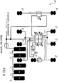
- FIG. 1 shows a compressed air system D for a vehicle, in particular a commercial vehicle.
- the compressed air system D comprises a plurality of compressed air consumers 2, which are uniformly provided with the reference numeral 2 and are designed as air springs for a front vehicle axle and a rear vehicle Doppelachss- / Zwillingsachs aggregate.
- the compressed air system D comprises a compressed air consumer 3 designed as a vehicle lift device 3, in particular as a lifting bellows.
- the compressed air consumers 2 and 3 can be supplied via a compressed air tank 1 with compressed air.
- the compressed air tank 1 is used in addition to the compressed air storage also for compressed air distribution to the compressed air consumers 2 and 3, so that it acts as a common rail compressed air tank and the functions compressed air storage and compressed air distribution component uniformly met.
- the common rail compressed air tank 1 makes it possible that between the compressed air tank 1 and the individual compressed air consumers 2 and 3 no separate to the compressed air tank 1, in particular the compressed air tank 1 in series downstream main distributor V * is required.
- the compressed air tank 1 comprises several, for the sake of clarity, only in the FIGS. 2 to 5 provided with reference numerals compressed air outlet openings 4, via which the compressed air distribution to the individual compressed air consumers 2 and 3 takes place.
- the compressed air tank 1 also includes several, for the sake of clarity, only in the FIGS. 2 to 5 provided with reference numerals compressed air connection openings 5, with which compressed air reservoir 6 are expediently removable connected to increase the compressed air capacity of the compressed air tank 1.
- a connection can serve as input or as output. Only the function determines whether it is a compressed air connections or compressed air outlets.
- a valve V1 is arranged between the compressed air tank 1 and the two in FIG. 1 Left air springs 2, a valve V1 is arranged.
- the air springs 2 are assigned to a front vehicle axle.
- the valve V1 can, for. B. be designed as a 2/2-way valve. It may preferably have two switching positions, for. B. to keep the pressure in the air springs 2 constant in a locked state and to lower the pressure in the air springs 2 via a vent.
- the air springs 2 are a central vehicle axle, z. B. assigned to a front axle of a dual axle / twin axle unit.
- the valve V2 can, for. B. be designed as a 3/3-way valve and z. B. have three switch positions. So it may be z. B. in a locked state to keep the pressure in the two air springs 2 constant, lower the pressure in the two air springs 2 via a vent and increase the pressure by means of the compressed air tank 1 in the two air springs 2 in an at least partially open state.
- valve V3 is arranged between the compressed air tank 1 and the two in FIG. 1 Middle.
- the air springs 2 are also associated with the central vehicle axle.
- the valve V3 can be designed analogously to the valve V2.
- a valve V4 is arranged between the compressed air tank 1 and in the FIG. 1 Rear, upper air spring 2 and the lifting device 3, a valve V4 is arranged.
- the air spring 2 and the lifting device 3 are assigned to the lift axle.
- the valve V4 can z. B. be designed as a 4/5-way valve and z. B. have five switch positions. So it may be z. B. in a locked state, the pressure in the air spring 2 and the lifting device 3 keep constant, via a vent the pressure in the air spring 2 or the lifting device 3 lower and in an at least partially open state, the pressure of the air spring 2 or the lifting device 3 means of the compressed air tank 1 increase.
- a valve V5 is arranged between the compressed air tank 1 and the in FIG. 1 Rear, lower air spring 2, a valve V5 is arranged.
- the air spring 2 is assigned to the rear vehicle axle.
- the valve V5 can z. B. be a 4/3-way valve and z. B. have three switch positions. So it may be z. B. in a locked state to keep the pressure in the air spring 2 constant, lower the pressure in the air spring 2 via a vent and increase the pressure in the air spring 2 by means of the compressed air tank 1 in an at least partially open state.
- a connection can serve to limit the pressure of the compressed air system D.
- the valve provided with the reference numeral 7 is expedient an overflow valve for residual pressure maintenance, so that when the compressor side is depressurized, the overflow valve 7 blocks and the lack of pressure in the compressed air system D, in particular in the compressed air consumers 2 and 3 prevented.
- the provided with the reference numeral 8 valve is z. B. a 4/2 way valve.
- the valve 8 can keep the pressure in the front air springs 2 constant in a locked state, lower the pressure via a vent and increase the pressure in the air springs 2 by means of the compressed air tank 1 in an at least partially open state.
- the valves 9 and 10 may be designed as pressure relief valves.
- the valve 11 may be designed as a quick release valve with air filter.
- the compressed air system D is designed in particular for a vehicle with a liftable trailing axle and so-called ramp adaptation, whereafter the vehicle can change its driving level even when the drive engine, in particular the internal combustion engine is switched off. So z. B. when loading the vehicle on a ramp to lower the driving level due to the additional weight by the load. Consequently, the pressure in the lift device 3 must be increased so that the vehicle can be adjusted to the appropriate driving level.
- FIGS. 2 to 5 show various views of a compressed air tank 1 according to an embodiment of the invention, the z. B. in the compressed air system D of FIG. 1 can be integrated.
- FIGS. 2 to 5 a plurality of compressed air openings can be seen, of which for clarity, only some are provided with the reference numerals 4 and 5 (compressed air outlet openings 4 for compressed air distribution to the individual compressed air consumers 2 and 3 and compressed air connection openings 5 for direct or indirect connection with the additional compressed air reservoirs 6 to increase the compressed air capacity of the compressed air tank 1).
- FIGS. 2 to 5 show that the compressed air outlet openings 4 and the compressed air connection openings 5 can be formed in the lateral surface of the compressed air tank 1 and in the end face of the compressed air tank 1.
- the compressed air tank 1 is elongated, preferably cylindrical, in particular circular cylindrical, executed and may have a length of at least 1 m or even at least 2m and preferably extend parallel to the longitudinal axis of the commercial vehicle.
Landscapes
- Engineering & Computer Science (AREA)
- Transportation (AREA)
- Mechanical Engineering (AREA)
- Vehicle Body Suspensions (AREA)
Abstract
Description
- Die Erfindung betrifft ein Druckluftsystem für ein Fahrzeug, insbesondere ein Nutzfahrzeug, z. B. einen Omnibus oder einen Lastkraftwagen.
-
Figur 6 zeigt ein aus der Praxis vorbekanntes Druckluftsystem D*. Das Druckluftsystem D* umfasst mehrere in Reihe hintereinander geschaltete Druckluftbehälter, die einheitlich mit dem Bezugszeichen 1* versehen sind, mehrere Druckluftverbraucher, z. B. mehrere Luftfedern, die einheitlich mit dem Bezugszeichen 2* versehen sind, und eine Lifteinrichtung 3* zum Heben und Senken einer Fahrzeug-Achse. - Zwischen den Druckluftbehältern 1* und den Druckluftverbrauchern 2* und 3* ist ein Hauptverteiler V* angeordnet, um die Druckluft aus den Druckluftbehältern 1* an die einzelnen Druckluftverbraucher 2* und 3* zu verteilen. Die Druckluftbehälter 1* und der Hauptverteiler V* sind separate Bauteile und in Reihe verbaut, um die Funktionen Druckluftspeicherung und Druckluftverteilung bauteilseparat zu realisieren.
- Eine Aufgabe der Erfindung ist es, ein verbessertes und/oder alternatives Druckluftsystem zu schaffen, insbesondere ein Druckluftsystem, mittels dem Druckluftleitungswege zu Druckluftverbrauchern verkürzt und/oder eingespart werden können.
- Diese Aufgabe kann mit den Merkmalen des Hauptanspruchs gelöst werden. Vorteilhafte Weiterbildungen der Erfindung können den Unteransprüchen und der folgenden Beschreibung bevorzugter Ausführungsformen der Erfindung entnommen werden.
- Die Erfindung schafft ein Druckluftsystem für ein Fahrzeug, insbesondere ein Nutzfahrzeug, z. B. einen Omnibus oder einen Lastkraftwagen. Das Druckluftsystem umfasst einen Druckluftbehälter und mehrere Druckluftverbraucher, die mittels des Druckluftbehälters mit Druckluft versorgbar sind.
- Der Druckluftbehälter ist zweckmäßig zusätzlich zur Druckluftspeicherung ebenfalls zur Druckluftverteilung, insbesondere über eine Vielzahl an Druckluftausgangsöffnungen, an die mehreren Druckluftverbraucher ausgeführt ist, so dass vorzugsweise die Funktionen Druckluftspeicherung und Druckluftverteilung bauteileinheitlich realisierbar sind. Der Druckluftbehälter kann somit zweckmäßig als Commonrail-Druckluftbehälter bezeichnet werden.
- Der vorzugsweise als Commonrail-Druckluftbehälter ausgeführte Druckluftbehälter verbindet somit die Funktionen der Druckluftspeicherung und der Druckluftverteilung zweckmäßig in einem Bauteil. Dadurch können z. B. Druckluftbehälter, Halterungen und Druckluft-Leitungswege eingespart werden, insbesondere aber der zuvor erwähnte Hauptverteiler des Stands der Technik. Darüber hinaus kann ein einheitlicher (z. B. zentraler) Einbauort für die Funktionen Druckluftspeicherung und Druckluftverteilung gewährleistet werden.
- Dadurch, dass der Druckluftbehälter vorzugsweise länglich ausgeführt ist, kann er sich zweckmäßig beabstandet, aber entlang zumindest einiger Druckluftverbraucher erstrecken, so dass vorzugsweise die Druckluftwege vom Druckluftbehälter zu den einzelnen Druckluftverbrauchern relativ kurz gehalten werden können.
- Der Druckluftbehälter weist vorzugsweise eine Vielzahl von Öffnungen, z. B. zumindest 10, zumindest 15 oder sogar zumindest 20 auf, so dass er flexibel eingesetzt werden kann. Dadurch können je nach Anwendungsbedarf verschiedene Druckluftverbraucher, zusätzliche Druckluftbehälter, Druckregler, Ventile, Rückschlagventile, Drosseln, etc. an die Öffnungen angeschlossen werden.
- Der Druckluftbehälter kann insbesondere zum Verteilen der Druckluft an Druckluftverbraucher unterschiedlicher Fahrzeugachsen (z. B. einer vorderen und einer hinteren Fahrzeugachse) und/oder unterschiedlicher Druckluftverbraucher (z. B. Luftfedern und Lifteinrichtung, unterschiedliche Fahrzeug-Bremskreisläufe (z. B. für Fahrzeug-Vorderräder und Fahrzeug-Hinterräder), etc.) dienen, insbesondere unterschiedlicher Druckluftkreise, die vorzugsweise unabhängig voneinander betreibbar sind.
- Z. B. kann Druckluft für die Bremsanlage über den Druckluftbehälter verteilt werden. Eine Fahrzeug-Bremsanlage kann z. B. auf zwei unterschiedliche Druckluftkreise aufgeteilt werden, die unabhängig voneinander sind.
- Der Druckluftbehälter umfasst vorzugsweise mehrere Druckluftausgangsöffnungen, über die die Druckluftverteilung an die einzelnen Druckluftverbraucher erfolgt. Alternativ oder ergänzend kann der Druckluftbehälter mehrere Druckluftanschlussöffnungen aufweisen, mit denen mehrere Druckluftspeicher zur Erhöhung des Druckluftaufnahmevermögens des Druckluftbehälters mittelbar oder unmittelbar verbunden werden können.
- Es ist möglich, dass mehrere Druckluftausgangsöffnungen in der Mantelfläche des Druckluftbehälters ausgebildet sind. Alternativ oder ergänzend kann zumindest eine Druckluftausgangsöffnung in der Stirnseite des Druckluftbehälters ausgebildet sein.
- Es ist ebenfalls möglich, dass mehrere Druckluftanschlussöffnungen in der Mantelfläche des Druckluftbehälters ausgebildet sind und/oder zumindest eine Druckluftanschlussöffnung in der Stirnseite des Druckluftbehälters ausgebildet ist:
- Druckluftanschlussöffnungen und Druckluftausgangsöffnungen sind vorzugsweise baulich gleich. Eine Öffnung (Anschluss) kann z. B. als Eingang oder als Ausgang dienen. Allein die Funktion bestimmt vorzugsweise, ob es ein Druckluftanschluss oder Druckluftausgang ist.
- Es ist möglich, dass die Druckluftverbraucher mehrere Fahrzeug-Luftfedern umfassen und/oder zumindest eine zum Senken und Heben einer Fahrzeugachse ausgebildete Fahrzeug-Lifteinrichtung, z. B. einen Fahrzeug-Liftbalg. Alternativ oder ergänzend können die Druckluftverbraucher mehrere Bremseinrichtungen für Fahrzeugräder umfassen.
- Eine Liftachse ist üblicherweise zweckmäßig mit Luftfedern versehen. Luftfedern ohne Liftachse sind zweckmäßig möglich.
- Das Druckluftsystem kann z. B. ausgeführt sein, um mittels der Fahrzeug-Luftfedern das Fahrzeug-Fahr-Niveau trotz ausgeschalteter Fahrzeug-Antriebsmaschine (z. B. ein Verbrennungsmotor, etc.) zu heben und zu senken.
- Die Fahrzeug-Lifteinrichtung kann z. B. Teil einer liftbaren Nachlaufachse sein.
- Die Liftachse ist vorzugsweise eine Hinterachse, die komplett mit Rädern angehoben/gesenkt werden kann. Wenn der LKW z. B. unbeladen ist, benötigt er diese Achse üblicherweise nicht. Sie wird angehoben um Reibung/Verbrauch zu minimieren und den Reifenverschleiß zu senken. Die Liftachse beeinflusst üblicherweise das Fahrniveau nicht. Für das Fahrniveau sind insbesondere die Luftfedern zuständig.
- Das Druckluftsystem umfasst folglich vorzugsweise eine liftbare Nachlaufachse und/oder ist zur Rampenanpassungen ausgeführt.
- Es ist möglich, dass zwischen dem Druckluftbehälter (Commonrail-Druckluftbehälter) und den einzelnen Druckluftverbrauchern jeweils ein Ventil zur Steuerung der Druckluft ausgebildet ist. Das oder die Ventile können z. B. an den Druckluftbehälter anmontiert sein (z. B. an von der Mantelfläche des Druckluftbehälters abstehende Montageflansche) oder vom Druckluftbehälter räumlich beabstandet zwischen dem Druckluftbehälter und dem zugehörigen Druckluftverbraucher angeordnet sein, z. B. an den Druckluftverbraucher anmontiert sein.
- Als Ventile können zweckmäßig Ventile mit Druckregler eingesetzt werden und alternativ oder ergänzend z. B. Rückschlagventile, Drosseln, etc. und andere zweckmäßige Steuer-/Regelelemente.
- Zumindest eines der Ventile kann z. B. dazu dienen, um in einem gesperrten Zustand den Druck im zugehörigen Druckluftverbraucher konstant zu halten, um über einen Entlüfter den Druck im zugehörigen Druckluftverbraucher zu senken, und/oder um in einem zumindest teilweise geöffneten Zustand den Druck im zugehörigen Druckluftverbraucher mittels des Druckluftbehälters zu erhöhen.
- Zumindest eines der Ventile dient vorzugsweise zur Steuerung der Druckluft an die Fahrzeug-Luftfeder und zur Steuerung der Druckluft an die zum Heben und Senken einer Fahrzeugachse ausgebildete Fahrzeug-Lifteinrichtung. Das hierzu verwendete Ventil kann z. B. ein 4/5-Wegeventil sein.
- Das Druckluftsystem kann z. B. ein Drucksteuermittel aufweisen, um einen vordefinierten Druck im Druckluftbehälter zu gewährleisten.
- Der Druckluftbehälter weist eine vorzugsweise längliche zylinderförmige Form auf und/oder ist vorzugsweise zumindest 1 m oder zumindest 2m lang. Alternativ oder ergänzend erstreckt er sich vorzugsweise im Wesentlichen parallel zur Fahrzeug-Längsachse. Er kann z. B. einen Durchmesser von über 150 mm oder sogar größer oder gleich 200 mm aufweisen.
- Der Druckluftbehälter ermöglicht insbesondere, dass auf einen Hauptverteiler verzichtet werden kann, der separat zum Druckluftbehälter und/oder in Reihe dahinter ausgebildet und zum Verteilen der Druckluft an Druckluftverbraucher unterschiedlicher Fahrzeugachsen ausgebildet ist.
- Das Merkmal "Luft" ist im Rahmen der Erfindung breit auszulegen und kann z. B. auch ein anderes Gas als Luft umfassen.
- Das Merkmal "Steuern" ist im Rahmen der Erfindung ebenfalls breit auszulegen und kann zweckmäßig z. B. auch ein Regeln umfassen.
- Die Erfindung ist nicht auf ein Druckluftsystem beschränkt, sondern umfasst auch ein Fahrzeug, insbesondere ein Nutzfahrzeug, z. B. einen Omnibus oder einen Lastkraftwagen, mit einem Druckluftsystem wie hierin beschrieben.
- Die vorstehend beschriebenen bevorzugten Ausführungsformen und Merkmale der Erfindung sind miteinander kombinierbar. Andere vorteilhafte Weiterbildungen der Erfindung sind in den Unteransprüchen offenbart oder ergeben sich aus der folgenden Beschreibung bevorzugter Ausführungsformen der Erfindung in Verbindung mit den beigefügten Figuren.
- Figur 1
- zeigt ein Druckluftsystem gemäß einer Ausführungsform der Erfindung,
- Figur 2
- zeigt eine perspektivische Ansicht eines Druckluftbehälters gemäß einer Ausführungsform der Erfindung,
- Figur 3
- zeigt eine Seitenansicht des Druckluftbehälters der
Figur 2 , - Figur 4
- zeigt eine Draufsicht auf den Druckluftbehälter der
Figuren 2 und 3 , - Figur 5
- zeigt eine Frontalansicht des Druckluftbehälters der
Figuren 2 bis 4 , und - Figur 6
- zeigt ein Druckluftsystem des Stands der Technik.
-
Figur 1 zeigt ein Druckluftsystem D für ein Fahrzeug, insbesondere ein Nutzfahrzeug. Das Druckluftsystem D umfasst eine Vielzahl an Druckluftverbrauchern 2, die einheitlich mit dem Bezugszeichen 2 versehen sind und als Luftfedern für eine vordere Fahrzeugachse und ein hinteres Fahrzeug-Doppelachs-/Zwillingsachs-Aggregat ausgeführt sind. Darüber hinaus umfasst das Druckluftsystem D einen als Fahrzeug-Lifteinrichtung 3, insbesondere als Liftbalg, ausgebildeten Druckluftverbraucher 3. - Die Druckluftverbraucher 2 und 3 können über einen Druckluftbehälter 1 mit Druckluft versorgt werden.
- Der Druckluftbehälter 1 dient zusätzlich zur Druckluftspeicherung ebenfalls zur Druckluftverteilung an die Druckluftverbraucher 2 und 3, so dass er als Commonrail-Druckluftbehälter wirkt und die Funktionen Druckluftspeicherung und Druckluftverteilung bauteileinheitlich erfüllt.
- Der Commonrail-Druckluftbehälter 1 ermöglicht es, dass zwischen dem Druckluftbehälter 1 und den einzelnen Druckluftverbrauchern 2 und 3 kein zum Druckluftbehälter 1 separater, insbesondere dem Druckluftbehälter 1 in Reihe nachgeschalteter Hauptverteiler V* erforderlich ist.
- Der Druckluftbehälter 1 umfasst mehrere, der Übersichtlichkeit halber nur in den
Figuren 2 bis 5 mit Bezugszeichen versehene Druckluftausgangsöffnungen 4, über die die Druckluftverteilung an die einzelnen Druckluftverbraucher 2 und 3 erfolgt. - Der Druckluftbehälter 1 umfasst darüber hinaus mehrere, der Übersichtlichkeit halber nur in den
Figuren 2 bis 5 mit Bezugszeichen versehene Druckluftanschlussöffnungen 5, mit denen Druckluftspeicher 6 zur Erhöhung des Druckluftaufnahmevermögens des Druckluftbehälters 1 zweckmäßig demontierbar verbindbar sind. - Die Druckluftanschlüsse und Druckluftausgänge sind zweckmäßig baulich gleich. Ein Anschluss kann als Eingang oder als Ausgang dienen. Allein die Funktion bestimmt, ob es ein Druckluftanschlüsse oder Druckluftausgänge sind.
- Zwischen dem Druckluftbehälter 1 und den zwei in
Figur 1 linken Luftfedern 2 ist ein Ventil V1 angeordnet. Die Luftfedern 2 sind einer vorderen Fahrzeugachse zugeordnet. Das Ventil V1 kann z. B. als 2/2-Wegeventil ausgeführt sein. Es kann vorzugsweise zwei Schaltstellungen aufweisen, z. B. um in einem gesperrten Zustand den Druck in den Luftfedern 2 konstant zu halten und um über eine Entlüftung den Druck in den Luftfedern 2 zu senken. - Zwischen dem Druckluftbehälter 1 und den zwei in
Figur 1 oberen, mittleren Luftfedern 2 ist ein Ventil V2 angeordnet.. Die Luftfedern 2 sind einer mittleren Fahrzeugachse, z. B. einer vorderen Achse eines Doppelachs-/Zwillingsachs-Aggregats zugeordnet. Das Ventil V2 kann z. B. als 3/3-Wegeventil ausgeführt sein und z. B. drei Schaltstellungen aufweisen. So kann es z. B. in einem gesperrten Zustand den Druck in den zwei Luftfedern 2 konstant halten, über eine Entlüftung den Druck in den zwei Luftfedern 2 senken und in einem zumindest teilweise geöffneten Zustand den Druck mittels des Druckluftbehälters 1 in den zwei Luftfedern 2 erhöhen. - Zwischen dem Druckluftbehälter 1 und den zwei in
Figur 1 mittleren, unteren Luftfedern 2 ist ein Ventil V3 angeordnet. Die Luftfedern 2 sind ebenfalls der mittleren Fahrzeugachse zugeordnet. Das Ventil V3 kann analog dem Ventil V2 ausgeführt sein. - Zwischen dem Druckluftbehälter 1 und der in der
Figur 1 hinteren, oberen Luftfeder 2 und der Lifteinrichtung 3 ist ein Ventil V4 angeordnet. Die Luftfeder 2 und die Lifteinrichtung 3 sind der Liftachse zugeordnet. Das Ventil V4 kann z. B. als 4/5-Wegeventil ausgeführt sein und z. B. fünf Schaltstellungen aufweisen. So kann es z. B. in einem gesperrten Zustand den Druck in der Luftfeder 2 und der Lifteinrichtung 3 konstant halten, über eine Entlüftung den Druck in der Luftfeder 2 oder der Lifteinrichtung 3 senken und in einem zumindest teilweise geöffneten Zustand den Druck der Luftfeder 2 oder der Lifteinrichtung 3 mittels des Druckluftbehälters 1 erhöhen. - Zwischen dem Druckluftbehälter 1 und der in
Figur 1 hinteren, unteren Luftfeder 2 ist ein Ventil V5 angeordnet. Die Luftfeder 2 ist der hinteren Fahrzeugachse zugeordnet. Das Ventil V5 kann z. B. ein 4/3-Wegeventil sein und z. B. drei Schaltstellungen aufweisen. So kann es z. B. in einem gesperrten Zustand den Druck in der Luftfeder 2 konstant halten, über eine Entlüftung den Druck in der Luftfeder 2 senken und in einem zumindest teilweise geöffneten Zustand den Druck in der Luftfeder 2 mittels des Druckluftbehälters 1 erhöhen. Zudem kann ein Anschluss zur Druckbegrenzung des Druckluftsystems D dienen. - Das mit dem Bezugszeichen 7 versehene Ventil ist zweckmäßig ein Überströmventil zur Restdruckerhaltung, so dass, wenn die Kompressorseite drucklos ist, das Überströmventil 7 sperrt und die Drucklosigkeit im Druckluftsystem D, insbesondere in den Druckluftverbrauchern 2 und 3, verhindert.
- Das mit dem Bezugszeichen 8 versehene Ventil ist z. B. ein 4/2 Wegeventil. Das Ventil 8 kann in einem gesperrten Zustand den Druck in den vorderen Luftfedern 2 konstant halten, über eine Entlüftung den Druck senken und in einem zumindest teilweise geöffneten Zustand den Druck in den Luftfedern 2 mittels des Druckluftbehälters 1 erhöhen.
- Die Ventile 9 und 10 können als Druckbegrenzungsventile ausgeführt sein.
- Das Ventil 11 kann als Schnelllöseventil mit Luftfilter ausgeführt sein.
- Zu erwähnen ist noch, dass das Druckluftsystem D insbesondere für ein Fahrzeug mit liftbarer Nachlaufachse und sogenannter Rampenanpassung ausgeführt ist, wonach das Fahrzeug auch bei ausgeschaltetem Antriebsmotor, insbesondere ausgeschalteter Verbrennungskraftmaschine, sein Fahrniveau verändern kann. So kann z. B. bei der Beladung des Fahrzeugs an einer Rampe sich das Fahrniveau aufgrund des Mehrgewichts durch die Beladung senken. Demzufolge muss der Druck in der Lifteinrichtung 3 erhöht werden, damit das Fahrzeug auf das angemessene Fahrniveau eingestellt werden kann.
- Die
Figuren 2 bis 5 zeigen verschiedene Ansichten eines Druckluftbehälters 1 gemäß einer Ausführungsform der Erfindung, der so z. B. in das Druckluftsystem D derFigur 1 integriert werden kann. - In den
Figuren 2 bis 5 ist eine Vielzahl an Druckluftöffnungen zu sehen, von denen der Übersichtlichkeit halber nur einige mit den Bezugszeichen 4 und 5 versehen sind (Druckluftausgangsöffnungen 4 zur Druckluftverteilung an die einzelnen Druckluftverbraucher 2 und 3 und Druckluftanschlussöffnungen 5 zum mittelbaren oder unmittelbaren Verbinden mit den zusätzlichen Druckluftspeichern 6 zur Erhöhung des Druckluftaufnahmevermögens des Druckluftbehälters 1). - Die
Figuren 2 bis 5 zeigen, dass die Druckluftausgangsöffnungen 4 und die Druckluftanschlussöffnungen 5 in der Mantelfläche des Druckluftbehälters 1 und in der Stirnseite des Druckluftbehälters 1 ausgebildet sein können. - Der Druckluftbehälter 1 ist länglich, vorzugsweise zylinderförmig, insbesondere kreiszylinderförmig, ausgeführt und kann eine Länge von zumindest 1 m oder sogar von zumindest 2m aufweisen und sich vorzugsweise parallel zur Längsachse des Nutzfahrzeugs erstrecken. Somit können z. B. Leitungswege hin zu den Druckluftverbrauchern 2 und 3 verkürzt oder vermieden werden.
- Die Erfindung ist nicht auf die oben beschriebenen bevorzugten Ausführungsformen beschränkt. Vielmehr ist eine Vielzahl von Varianten und Abwandlungen möglich, die ebenfalls von dem Erfindungsgedanken Gebrauch machen und deshalb in den Schutzbereich fallen. Darüber hinaus beansprucht die Erfindung auch Schutz für den Gegenstand und die Merkmale der Unteransprüche unabhängig von den in Bezug genommenen Merkmalen und Ansprüchen.
-
- 1
- Druckluftbehälter, insbesondere Commonrail-Druckluftbehälter
- 2
- Druckluftverbraucher, insbesondere Luftfeder
- 3
- Druckluftverbraucher, insbesondere Lifteinrichtung
- 4
- Druckluftausgangsöffnungen zur Druckluftverteilung an die einzelnen Druckluftverbraucher
- 5
- Druckluftanschlussöffnungen zur mittelbaren oder unmittelbaren Verbindung mit Druckluftspeichern zur Erhöhung des Druckluftaufnahmevermögens des Druckluftbehälters
- 6
- Zusätzliche Druckluftspeicher
- 7
- Ventil
- 8
- Ventil
- 9
- Ventil
- 10
- Ventil
- 11
- Ventil
- V1
- Ventil
- V2
- Ventil
- V3
- Ventil
- V4
- Ventil
- V5
- Ventil
- D
- Druckluftsystem
Claims (16)
- Druckluftsystem (D) für ein Fahrzeug, mit einem Druckluftbehälter (1) und mehreren Druckluftverbrauchern (2, 3), die mittels des Druckluftbehälters (1) mit Druckluft versorgbar sind, wobei der Druckluftbehälter (1) zusätzlich zur Druckluftspeicherung zur Druckluftverteilung an die mehreren Druckluftverbraucher (2, 3) dient, vorzugsweise über mehrere Druckluftausgangsöffnungen (4) und/oder so dass vorzugsweise die Funktionen Druckluftspeicherung und Druckluftverteilung bauteileinheitlich realisiert sind.
- Druckluftsystem (D) nach Anspruch 1, wobei der Druckluftbehälter (1) zum Verteilen der Druckluft an Druckluftverbraucher (2) unterschiedlicher Fahrzeugachsen und/oder unterschiedlicher Druckluftverbraucher (2, 3) dient.
- Druckluftsystem (D) nach Anspruch 1 oder 2, wobei die Druckluftausgangsöffnungen (4) in der Mantelfläche des Druckluftbehälters (1) ausgebildet sind und/oder zumindest eine Druckluftausgangsöffnung (4) in der Stirnseite des Druckluftbehälters (1) ausgebildet ist.
- Druckluftsystem (D) nach einem der vorhergehenden Ansprüche, wobei der Druckluftbehälter (1) mehrere Druckluftanschlussöffnungen (5) umfasst, mit denen Druckluftspeicher (6) zur Erhöhung des Druckluftaufnahmevermögens des Druckluftbehälters (1) verbindbar sind.
- Druckluftsystem (D) nach Anspruch 4, wobei die Druckluftanschlussöffnungen (5) in der Mantelfläche des Druckluftbehälters (1) ausgebildet sind und/oder zumindest eine Druckluftanschlussöffnung (5) in der Stirnseite des Druckluftbehälters (1) ausgebildet ist.
- Druckluftsystem (D) nach einem der vorhergehenden Ansprüche, wobei die Druckluftverbraucher (2, 3) mehrere Fahrzeug-Luftfedern (2) und/oder zumindest eine zum Senken und Heben einer Fahrzeug-Achse ausgebildete Fahrzeug-Lifteinrichtung (3) umfassen.
- Druckluftsystem (D) nach Anspruch 6, wobei das Druckluftsystem (D) ausgeführt ist, um mittels der Fahrzeug-Luftfedern (2) das Fahrzeug-Fahr-Niveau trotz ausgeschalteter Fahrzeug-Antriebsmaschine zu heben und zu senken.
- Druckluftsystem (D) nach Anspruch 6 oder 7, wobei die Fahrzeug-Lifteinrichtung (3) Teil einer liftbaren Nachlaufachse ist.
- Druckluftsystem (D) nach einem der vorhergehenden Ansprüche, wobei die Druckluftverbraucher Bremseinrichtungen für vorzugsweise vordere und hintere FahrzeugRäder umfassen.
- Druckluftsystem (D) nach einem der vorhergehenden Ansprüche, wobei zwischen dem Druckluftbehälter (1) und den einzelnen Druckluftverbrauchern (2, 3) jeweils ein Ventil (V1, V2, V3, V4, V5) zur Steuerung der Druckluft ausgebildet ist.
- Druckluftsystem (D) nach Anspruch 10, wobei zumindest eines der Ventile (V1, V2, V3, V4, V5) dazu dient, um in einem gesperrten Zustand den Druck im zugehörigen Druckluftverbraucher (2, 3) konstant zu halten, um über eine Entlüftung den Druck im zugehörigen Druckluftverbraucher (2, 3) zu senken, und/oder um in einem zumindest teilweise geöffneten Zustand den Druck im zugehörigen Druckluftverbraucher (2, 3) mittels des Druckluftbehälters (1) zu erhöhen.
- Druckluftsystem (D) nach Anspruch 10 oder 11, wobei zumindest eines der Ventile (V3) zur Steuerung der Druckluft an eine Fahrzeug-Luftfeder (2) und eine zum Heben und Senken einer Fahrzeug-Achse ausgebildete Fahrzeug-Lifteinrichtung (3) dient.
- Druckluftsystem (D) nach einem der vorhergehenden Ansprüche, wobei das Druckluftsystem (D) ein Drucksteuermittel (7) aufweist, um einen vordefinierten Druck im Druckluftbehälter (1) zu gewährleisten.
- Druckluftsystem (D) nach einem der vorhergehenden Ansprüche, wobei der Druckluftbehälter (1) eine längliche zylinderförmige Form aufweist und vorzugsweise zumindest 1 m oder zumindest 2m lang ist und/oder sich im Wesentlichen parallel zur Fahrzeug-Längsachse erstreckt.
- Druckluftsystem (D) nach einem der vorhergehenden Ansprüche, wobei das Druckluftsystem (D) keinen Hauptverteiler (V*) aufweist, der separat zum Druckluftbehälter (1) und vorzugsweise in Reihe dahinter ausgebildet und zum Verteilen der Druckluft an Druckluftverbraucher (2*) unterschiedlicher Fahrzeugachsen ausgebildet ist.
- Fahrzeug, insbesondere Nutzfahrzeug, mit einem Druckluftsystem (D) nach einem der vorhergehenden Ansprüche.
Applications Claiming Priority (1)
| Application Number | Priority Date | Filing Date | Title |
|---|---|---|---|
| DE102015016297.7A DE102015016297A1 (de) | 2015-12-16 | 2015-12-16 | Druckluftsystem mit Druckluftbehälter zur Druckluftspeicherung und zur Druckluftverteilung |
Publications (2)
| Publication Number | Publication Date |
|---|---|
| EP3181417A1 true EP3181417A1 (de) | 2017-06-21 |
| EP3181417B1 EP3181417B1 (de) | 2021-01-06 |
Family
ID=57348423
Family Applications (1)
| Application Number | Title | Priority Date | Filing Date |
|---|---|---|---|
| EP16002436.0A Active EP3181417B1 (de) | 2015-12-16 | 2016-11-16 | Druckluftsystem mit druckluftbehälter zur druckluftspeicherung und zur druckluftverteilung |
Country Status (2)
| Country | Link |
|---|---|
| EP (1) | EP3181417B1 (de) |
| DE (1) | DE102015016297A1 (de) |
Cited By (1)
| Publication number | Priority date | Publication date | Assignee | Title |
|---|---|---|---|---|
| CN115898815A (zh) * | 2022-11-14 | 2023-04-04 | 中国第一汽车股份有限公司 | 一种空气压缩机系统及应用 |
Citations (3)
| Publication number | Priority date | Publication date | Assignee | Title |
|---|---|---|---|---|
| WO1999043527A1 (en) * | 1998-02-25 | 1999-09-02 | Alliedsignal Inc. | Air dryer reservoir module components |
| US20050168058A1 (en) * | 2003-08-08 | 2005-08-04 | Eberling Charles E. | Air system module including reservoir and mounting structure |
| KR20080032571A (ko) * | 2006-10-10 | 2008-04-15 | 현대자동차주식회사 | 상용차용 공압 브레이크 시스템 |
-
2015
- 2015-12-16 DE DE102015016297.7A patent/DE102015016297A1/de not_active Withdrawn
-
2016
- 2016-11-16 EP EP16002436.0A patent/EP3181417B1/de active Active
Patent Citations (3)
| Publication number | Priority date | Publication date | Assignee | Title |
|---|---|---|---|---|
| WO1999043527A1 (en) * | 1998-02-25 | 1999-09-02 | Alliedsignal Inc. | Air dryer reservoir module components |
| US20050168058A1 (en) * | 2003-08-08 | 2005-08-04 | Eberling Charles E. | Air system module including reservoir and mounting structure |
| KR20080032571A (ko) * | 2006-10-10 | 2008-04-15 | 현대자동차주식회사 | 상용차용 공압 브레이크 시스템 |
Cited By (1)
| Publication number | Priority date | Publication date | Assignee | Title |
|---|---|---|---|---|
| CN115898815A (zh) * | 2022-11-14 | 2023-04-04 | 中国第一汽车股份有限公司 | 一种空气压缩机系统及应用 |
Also Published As
| Publication number | Publication date |
|---|---|
| EP3181417B1 (de) | 2021-01-06 |
| DE102015016297A1 (de) | 2017-06-22 |
Similar Documents
| Publication | Publication Date | Title |
|---|---|---|
| EP3691942B1 (de) | Parkbrems-ventileinrichtung | |
| WO2013091776A2 (de) | Luftfederungsanlage eines kraftfahrzeugs und verfahren zu deren steuerung | |
| EP2168788A1 (de) | Vorrichtung und Verfahren zum Durchführen einer Radstandregelung für Nutzfahrzeuge | |
| EP1884430A2 (de) | Druckluftaufbereitungseinrichtung zum Versorgen einer Kraftfahrzeugbremsanlage mit Druckluft | |
| EP2836406A1 (de) | Luftaufbereitungsanlage für die druckluftversorgung von nutzkraftfahrzeugen | |
| EP2540536A1 (de) | Niveauregelventileinheit | |
| DE2056634A1 (de) | Luftfederung, insbesondere für Kraftfahrzeuge | |
| EP2106937B1 (de) | Nutzfahrzeug mit einer Gasfederung, insbesondere Luftfederung und Gasfederungssystem | |
| DE102015115082B4 (de) | Ventileinheit für pneumatische Anwendungen sowie Luftfederungsanlage | |
| DE102010054108A1 (de) | Ventilanordnung zur Steuerung eines Zusatz-Lenksystems bei mehrachsigen Fahrzeugen, insbesondere Mobilkranen | |
| EP3181417B1 (de) | Druckluftsystem mit druckluftbehälter zur druckluftspeicherung und zur druckluftverteilung | |
| DE102004051812A1 (de) | Druckluftversorgungseinrichtung und Verfahren zum Betreiben einer Druckluftversorgungseinrichtung | |
| EP2572909B1 (de) | Ventileinrichtung für eine luftfederungseinrichtung für ein fahrzeug | |
| DE102005030467B4 (de) | Luftfederungseinrichtung für Fahrzeuge mit Drossel | |
| DE102019105791A1 (de) | Verfahren zur Niveauregulierung eines luftgefederten Fahrzeugs sowie Vorrichtung hierzu | |
| DE102010010605B4 (de) | Vorrichtung zur Steuerung von pneumatischen Einrichtungen eines Anhängers | |
| EP3793872B1 (de) | Fahrzeugkran mit hydropneumatischer federung und einem wenigstens zwei bremskreise umfassenden bremssystem | |
| DE112010001652B4 (de) | Kraftfahrzeug mit einem Luftfederungssystem und Computerprogramm zur Steuerung eines Luftfederungssystems | |
| WO2020229138A1 (de) | Sensoranordnung einer luftfederungsanlage eines fahrzeugs | |
| EP2957441B1 (de) | Luftfederungseinrichtung zum heben und senken eines fahrzeugaufbaus | |
| EP2307254B1 (de) | Luftfedersystem für ein schienenfahrzeug | |
| DE102017001653A1 (de) | Federungsvorrichtung | |
| DE102015223614A1 (de) | Geschlossene niveauregelnde Anlage für Fahrzeuge mit druckgeregeltem Zusatzverbraucher | |
| DE102015118049A1 (de) | Fahrzeug mit verbesserter Anhängervorrichtung | |
| EP2769858B1 (de) | Einrichtung zur steuerung der deichsellast bei mehrachsigen anhängern |
Legal Events
| Date | Code | Title | Description |
|---|---|---|---|
| PUAI | Public reference made under article 153(3) epc to a published international application that has entered the european phase |
Free format text: ORIGINAL CODE: 0009012 |
|
| STAA | Information on the status of an ep patent application or granted ep patent |
Free format text: STATUS: THE APPLICATION HAS BEEN PUBLISHED |
|
| AK | Designated contracting states |
Kind code of ref document: A1 Designated state(s): AL AT BE BG CH CY CZ DE DK EE ES FI FR GB GR HR HU IE IS IT LI LT LU LV MC MK MT NL NO PL PT RO RS SE SI SK SM TR |
|
| AX | Request for extension of the european patent |
Extension state: BA ME |
|
| STAA | Information on the status of an ep patent application or granted ep patent |
Free format text: STATUS: REQUEST FOR EXAMINATION WAS MADE |
|
| 17P | Request for examination filed |
Effective date: 20171019 |
|
| RBV | Designated contracting states (corrected) |
Designated state(s): AL AT BE BG CH CY CZ DE DK EE ES FI FR GB GR HR HU IE IS IT LI LT LU LV MC MK MT NL NO PL PT RO RS SE SI SK SM TR |
|
| RAP1 | Party data changed (applicant data changed or rights of an application transferred) |
Owner name: MAN TRUCK & BUS SE |
|
| GRAP | Despatch of communication of intention to grant a patent |
Free format text: ORIGINAL CODE: EPIDOSNIGR1 |
|
| STAA | Information on the status of an ep patent application or granted ep patent |
Free format text: STATUS: GRANT OF PATENT IS INTENDED |
|
| RIC1 | Information provided on ipc code assigned before grant |
Ipc: B60T 17/06 20060101ALI20200625BHEP Ipc: B60T 13/26 20060101AFI20200625BHEP |
|
| INTG | Intention to grant announced |
Effective date: 20200710 |
|
| GRAS | Grant fee paid |
Free format text: ORIGINAL CODE: EPIDOSNIGR3 |
|
| GRAA | (expected) grant |
Free format text: ORIGINAL CODE: 0009210 |
|
| STAA | Information on the status of an ep patent application or granted ep patent |
Free format text: STATUS: THE PATENT HAS BEEN GRANTED |
|
| AK | Designated contracting states |
Kind code of ref document: B1 Designated state(s): AL AT BE BG CH CY CZ DE DK EE ES FI FR GB GR HR HU IE IS IT LI LT LU LV MC MK MT NL NO PL PT RO RS SE SI SK SM TR |
|
| REG | Reference to a national code |
Ref country code: GB Ref legal event code: FG4D Free format text: NOT ENGLISH |
|
| REG | Reference to a national code |
Ref country code: AT Ref legal event code: REF Ref document number: 1352029 Country of ref document: AT Kind code of ref document: T Effective date: 20210115 Ref country code: CH Ref legal event code: EP |
|
| REG | Reference to a national code |
Ref country code: DE Ref legal event code: R096 Ref document number: 502016012105 Country of ref document: DE |
|
| REG | Reference to a national code |
Ref country code: IE Ref legal event code: FG4D Free format text: LANGUAGE OF EP DOCUMENT: GERMAN |
|
| REG | Reference to a national code |
Ref country code: SE Ref legal event code: TRGR |
|
| REG | Reference to a national code |
Ref country code: NL Ref legal event code: FP |
|
| REG | Reference to a national code |
Ref country code: LT Ref legal event code: MG9D |
|
| PG25 | Lapsed in a contracting state [announced via postgrant information from national office to epo] |
Ref country code: PT Free format text: LAPSE BECAUSE OF FAILURE TO SUBMIT A TRANSLATION OF THE DESCRIPTION OR TO PAY THE FEE WITHIN THE PRESCRIBED TIME-LIMIT Effective date: 20210506 Ref country code: NO Free format text: LAPSE BECAUSE OF FAILURE TO SUBMIT A TRANSLATION OF THE DESCRIPTION OR TO PAY THE FEE WITHIN THE PRESCRIBED TIME-LIMIT Effective date: 20210406 Ref country code: FI Free format text: LAPSE BECAUSE OF FAILURE TO SUBMIT A TRANSLATION OF THE DESCRIPTION OR TO PAY THE FEE WITHIN THE PRESCRIBED TIME-LIMIT Effective date: 20210106 Ref country code: GR Free format text: LAPSE BECAUSE OF FAILURE TO SUBMIT A TRANSLATION OF THE DESCRIPTION OR TO PAY THE FEE WITHIN THE PRESCRIBED TIME-LIMIT Effective date: 20210407 Ref country code: HR Free format text: LAPSE BECAUSE OF FAILURE TO SUBMIT A TRANSLATION OF THE DESCRIPTION OR TO PAY THE FEE WITHIN THE PRESCRIBED TIME-LIMIT Effective date: 20210106 Ref country code: LT Free format text: LAPSE BECAUSE OF FAILURE TO SUBMIT A TRANSLATION OF THE DESCRIPTION OR TO PAY THE FEE WITHIN THE PRESCRIBED TIME-LIMIT Effective date: 20210106 Ref country code: BG Free format text: LAPSE BECAUSE OF FAILURE TO SUBMIT A TRANSLATION OF THE DESCRIPTION OR TO PAY THE FEE WITHIN THE PRESCRIBED TIME-LIMIT Effective date: 20210406 |
|
| PG25 | Lapsed in a contracting state [announced via postgrant information from national office to epo] |
Ref country code: RS Free format text: LAPSE BECAUSE OF FAILURE TO SUBMIT A TRANSLATION OF THE DESCRIPTION OR TO PAY THE FEE WITHIN THE PRESCRIBED TIME-LIMIT Effective date: 20210106 Ref country code: LV Free format text: LAPSE BECAUSE OF FAILURE TO SUBMIT A TRANSLATION OF THE DESCRIPTION OR TO PAY THE FEE WITHIN THE PRESCRIBED TIME-LIMIT Effective date: 20210106 Ref country code: PL Free format text: LAPSE BECAUSE OF FAILURE TO SUBMIT A TRANSLATION OF THE DESCRIPTION OR TO PAY THE FEE WITHIN THE PRESCRIBED TIME-LIMIT Effective date: 20210106 |
|
| PG25 | Lapsed in a contracting state [announced via postgrant information from national office to epo] |
Ref country code: IS Free format text: LAPSE BECAUSE OF FAILURE TO SUBMIT A TRANSLATION OF THE DESCRIPTION OR TO PAY THE FEE WITHIN THE PRESCRIBED TIME-LIMIT Effective date: 20210506 |
|
| REG | Reference to a national code |
Ref country code: DE Ref legal event code: R097 Ref document number: 502016012105 Country of ref document: DE |
|
| PG25 | Lapsed in a contracting state [announced via postgrant information from national office to epo] |
Ref country code: EE Free format text: LAPSE BECAUSE OF FAILURE TO SUBMIT A TRANSLATION OF THE DESCRIPTION OR TO PAY THE FEE WITHIN THE PRESCRIBED TIME-LIMIT Effective date: 20210106 Ref country code: CZ Free format text: LAPSE BECAUSE OF FAILURE TO SUBMIT A TRANSLATION OF THE DESCRIPTION OR TO PAY THE FEE WITHIN THE PRESCRIBED TIME-LIMIT Effective date: 20210106 Ref country code: SM Free format text: LAPSE BECAUSE OF FAILURE TO SUBMIT A TRANSLATION OF THE DESCRIPTION OR TO PAY THE FEE WITHIN THE PRESCRIBED TIME-LIMIT Effective date: 20210106 |
|
| PLBE | No opposition filed within time limit |
Free format text: ORIGINAL CODE: 0009261 |
|
| STAA | Information on the status of an ep patent application or granted ep patent |
Free format text: STATUS: NO OPPOSITION FILED WITHIN TIME LIMIT |
|
| PG25 | Lapsed in a contracting state [announced via postgrant information from national office to epo] |
Ref country code: SK Free format text: LAPSE BECAUSE OF FAILURE TO SUBMIT A TRANSLATION OF THE DESCRIPTION OR TO PAY THE FEE WITHIN THE PRESCRIBED TIME-LIMIT Effective date: 20210106 Ref country code: RO Free format text: LAPSE BECAUSE OF FAILURE TO SUBMIT A TRANSLATION OF THE DESCRIPTION OR TO PAY THE FEE WITHIN THE PRESCRIBED TIME-LIMIT Effective date: 20210106 Ref country code: DK Free format text: LAPSE BECAUSE OF FAILURE TO SUBMIT A TRANSLATION OF THE DESCRIPTION OR TO PAY THE FEE WITHIN THE PRESCRIBED TIME-LIMIT Effective date: 20210106 |
|
| 26N | No opposition filed |
Effective date: 20211007 |
|
| PG25 | Lapsed in a contracting state [announced via postgrant information from national office to epo] |
Ref country code: AL Free format text: LAPSE BECAUSE OF FAILURE TO SUBMIT A TRANSLATION OF THE DESCRIPTION OR TO PAY THE FEE WITHIN THE PRESCRIBED TIME-LIMIT Effective date: 20210106 Ref country code: ES Free format text: LAPSE BECAUSE OF FAILURE TO SUBMIT A TRANSLATION OF THE DESCRIPTION OR TO PAY THE FEE WITHIN THE PRESCRIBED TIME-LIMIT Effective date: 20210106 |
|
| PG25 | Lapsed in a contracting state [announced via postgrant information from national office to epo] |
Ref country code: SI Free format text: LAPSE BECAUSE OF FAILURE TO SUBMIT A TRANSLATION OF THE DESCRIPTION OR TO PAY THE FEE WITHIN THE PRESCRIBED TIME-LIMIT Effective date: 20210106 |
|
| PG25 | Lapsed in a contracting state [announced via postgrant information from national office to epo] |
Ref country code: IS Free format text: LAPSE BECAUSE OF FAILURE TO SUBMIT A TRANSLATION OF THE DESCRIPTION OR TO PAY THE FEE WITHIN THE PRESCRIBED TIME-LIMIT Effective date: 20210506 |
|
| PG25 | Lapsed in a contracting state [announced via postgrant information from national office to epo] |
Ref country code: MC Free format text: LAPSE BECAUSE OF FAILURE TO SUBMIT A TRANSLATION OF THE DESCRIPTION OR TO PAY THE FEE WITHIN THE PRESCRIBED TIME-LIMIT Effective date: 20210106 |
|
| REG | Reference to a national code |
Ref country code: CH Ref legal event code: PL |
|
| GBPC | Gb: european patent ceased through non-payment of renewal fee |
Effective date: 20211116 |
|
| PG25 | Lapsed in a contracting state [announced via postgrant information from national office to epo] |
Ref country code: LU Free format text: LAPSE BECAUSE OF NON-PAYMENT OF DUE FEES Effective date: 20211116 Ref country code: BE Free format text: LAPSE BECAUSE OF NON-PAYMENT OF DUE FEES Effective date: 20211130 |
|
| REG | Reference to a national code |
Ref country code: BE Ref legal event code: MM Effective date: 20211130 |
|
| PG25 | Lapsed in a contracting state [announced via postgrant information from national office to epo] |
Ref country code: LI Free format text: LAPSE BECAUSE OF NON-PAYMENT OF DUE FEES Effective date: 20211130 Ref country code: CH Free format text: LAPSE BECAUSE OF NON-PAYMENT OF DUE FEES Effective date: 20211130 |
|
| PG25 | Lapsed in a contracting state [announced via postgrant information from national office to epo] |
Ref country code: IE Free format text: LAPSE BECAUSE OF NON-PAYMENT OF DUE FEES Effective date: 20211116 Ref country code: GB Free format text: LAPSE BECAUSE OF NON-PAYMENT OF DUE FEES Effective date: 20211116 |
|
| REG | Reference to a national code |
Ref country code: AT Ref legal event code: MM01 Ref document number: 1352029 Country of ref document: AT Kind code of ref document: T Effective date: 20211116 |
|
| PG25 | Lapsed in a contracting state [announced via postgrant information from national office to epo] |
Ref country code: AT Free format text: LAPSE BECAUSE OF NON-PAYMENT OF DUE FEES Effective date: 20211116 |
|
| PG25 | Lapsed in a contracting state [announced via postgrant information from national office to epo] |
Ref country code: HU Free format text: LAPSE BECAUSE OF FAILURE TO SUBMIT A TRANSLATION OF THE DESCRIPTION OR TO PAY THE FEE WITHIN THE PRESCRIBED TIME-LIMIT; INVALID AB INITIO Effective date: 20161116 |
|
| PG25 | Lapsed in a contracting state [announced via postgrant information from national office to epo] |
Ref country code: CY Free format text: LAPSE BECAUSE OF FAILURE TO SUBMIT A TRANSLATION OF THE DESCRIPTION OR TO PAY THE FEE WITHIN THE PRESCRIBED TIME-LIMIT Effective date: 20210106 |
|
| PG25 | Lapsed in a contracting state [announced via postgrant information from national office to epo] |
Ref country code: MK Free format text: LAPSE BECAUSE OF FAILURE TO SUBMIT A TRANSLATION OF THE DESCRIPTION OR TO PAY THE FEE WITHIN THE PRESCRIBED TIME-LIMIT Effective date: 20210106 |
|
| PG25 | Lapsed in a contracting state [announced via postgrant information from national office to epo] |
Ref country code: TR Free format text: LAPSE BECAUSE OF FAILURE TO SUBMIT A TRANSLATION OF THE DESCRIPTION OR TO PAY THE FEE WITHIN THE PRESCRIBED TIME-LIMIT Effective date: 20210106 |
|
| PG25 | Lapsed in a contracting state [announced via postgrant information from national office to epo] |
Ref country code: MT Free format text: LAPSE BECAUSE OF FAILURE TO SUBMIT A TRANSLATION OF THE DESCRIPTION OR TO PAY THE FEE WITHIN THE PRESCRIBED TIME-LIMIT Effective date: 20210106 |
|
| PGFP | Annual fee paid to national office [announced via postgrant information from national office to epo] |
Ref country code: NL Payment date: 20251124 Year of fee payment: 10 |
|
| PGFP | Annual fee paid to national office [announced via postgrant information from national office to epo] |
Ref country code: DE Payment date: 20251126 Year of fee payment: 10 |
|
| PGFP | Annual fee paid to national office [announced via postgrant information from national office to epo] |
Ref country code: IT Payment date: 20251121 Year of fee payment: 10 |
|
| PGFP | Annual fee paid to national office [announced via postgrant information from national office to epo] |
Ref country code: FR Payment date: 20251124 Year of fee payment: 10 |
|
| PGFP | Annual fee paid to national office [announced via postgrant information from national office to epo] |
Ref country code: SE Payment date: 20251124 Year of fee payment: 10 |