EP3181339A1 - Bonding device and bonding method - Google Patents
Bonding device and bonding method Download PDFInfo
- Publication number
- EP3181339A1 EP3181339A1 EP15863240.6A EP15863240A EP3181339A1 EP 3181339 A1 EP3181339 A1 EP 3181339A1 EP 15863240 A EP15863240 A EP 15863240A EP 3181339 A1 EP3181339 A1 EP 3181339A1
- Authority
- EP
- European Patent Office
- Prior art keywords
- section
- patch
- corner
- object member
- bonded
- Prior art date
- Legal status (The legal status is an assumption and is not a legal conclusion. Google has not performed a legal analysis and makes no representation as to the accuracy of the status listed.)
- Granted
Links
- 238000000034 method Methods 0.000 title claims description 48
- 239000012783 reinforcing fiber Substances 0.000 claims abstract description 56
- 239000000463 material Substances 0.000 claims abstract description 23
- 230000006837 decompression Effects 0.000 claims abstract description 19
- 238000010438 heat treatment Methods 0.000 claims description 30
- 230000004044 response Effects 0.000 claims description 6
- 238000012546 transfer Methods 0.000 claims description 3
- 230000037303 wrinkles Effects 0.000 abstract description 30
- 239000000565 sealant Substances 0.000 abstract description 13
- 238000013461 design Methods 0.000 abstract description 7
- 229920005989 resin Polymers 0.000 description 27
- 239000011347 resin Substances 0.000 description 27
- 230000008569 process Effects 0.000 description 20
- 239000011159 matrix material Substances 0.000 description 15
- 238000007493 shaping process Methods 0.000 description 14
- 239000002131 composite material Substances 0.000 description 12
- 230000008439 repair process Effects 0.000 description 10
- 239000000835 fiber Substances 0.000 description 8
- 229920001187 thermosetting polymer Polymers 0.000 description 7
- -1 polyparaphenylene benzobisoxazole Polymers 0.000 description 5
- 229920005992 thermoplastic resin Polymers 0.000 description 5
- 238000002474 experimental method Methods 0.000 description 4
- 238000001816 cooling Methods 0.000 description 3
- 230000003247 decreasing effect Effects 0.000 description 3
- 238000004519 manufacturing process Methods 0.000 description 3
- 229920000459 Nitrile rubber Polymers 0.000 description 2
- ISWSIDIOOBJBQZ-UHFFFAOYSA-N Phenol Chemical compound OC1=CC=CC=C1 ISWSIDIOOBJBQZ-UHFFFAOYSA-N 0.000 description 2
- 239000004696 Poly ether ether ketone Substances 0.000 description 2
- 239000004697 Polyetherimide Substances 0.000 description 2
- 239000004734 Polyphenylene sulfide Substances 0.000 description 2
- XAGFODPZIPBFFR-UHFFFAOYSA-N aluminium Chemical compound [Al] XAGFODPZIPBFFR-UHFFFAOYSA-N 0.000 description 2
- 238000010586 diagram Methods 0.000 description 2
- 229920001971 elastomer Polymers 0.000 description 2
- 229920001643 poly(ether ketone) Polymers 0.000 description 2
- 229920001652 poly(etherketoneketone) Polymers 0.000 description 2
- 229920002530 polyetherether ketone Polymers 0.000 description 2
- 229920001601 polyetherimide Polymers 0.000 description 2
- 229920000069 polyphenylene sulfide Polymers 0.000 description 2
- 229920002379 silicone rubber Polymers 0.000 description 2
- 239000004945 silicone rubber Substances 0.000 description 2
- 238000001721 transfer moulding Methods 0.000 description 2
- XQUPVDVFXZDTLT-UHFFFAOYSA-N 1-[4-[[4-(2,5-dioxopyrrol-1-yl)phenyl]methyl]phenyl]pyrrole-2,5-dione Chemical compound O=C1C=CC(=O)N1C(C=C1)=CC=C1CC1=CC=C(N2C(C=CC2=O)=O)C=C1 XQUPVDVFXZDTLT-UHFFFAOYSA-N 0.000 description 1
- CMLFRMDBDNHMRA-UHFFFAOYSA-N 2h-1,2-benzoxazine Chemical compound C1=CC=C2C=CNOC2=C1 CMLFRMDBDNHMRA-UHFFFAOYSA-N 0.000 description 1
- 229920000049 Carbon (fiber) Polymers 0.000 description 1
- RYGMFSIKBFXOCR-UHFFFAOYSA-N Copper Chemical compound [Cu] RYGMFSIKBFXOCR-UHFFFAOYSA-N 0.000 description 1
- 239000004593 Epoxy Substances 0.000 description 1
- 229920000181 Ethylene propylene rubber Polymers 0.000 description 1
- 244000043261 Hevea brasiliensis Species 0.000 description 1
- 239000004677 Nylon Substances 0.000 description 1
- 239000004952 Polyamide Substances 0.000 description 1
- 239000004698 Polyethylene Substances 0.000 description 1
- 239000004642 Polyimide Substances 0.000 description 1
- 239000004372 Polyvinyl alcohol Substances 0.000 description 1
- 229920006311 Urethane elastomer Polymers 0.000 description 1
- 239000000654 additive Substances 0.000 description 1
- 230000000996 additive effect Effects 0.000 description 1
- 239000000853 adhesive Substances 0.000 description 1
- 230000001070 adhesive effect Effects 0.000 description 1
- 238000013459 approach Methods 0.000 description 1
- 229920006231 aramid fiber Polymers 0.000 description 1
- 238000011074 autoclave method Methods 0.000 description 1
- 238000005452 bending Methods 0.000 description 1
- 230000005540 biological transmission Effects 0.000 description 1
- 229920005549 butyl rubber Polymers 0.000 description 1
- 239000004917 carbon fiber Substances 0.000 description 1
- 239000000919 ceramic Substances 0.000 description 1
- 230000008859 change Effects 0.000 description 1
- 239000003795 chemical substances by application Substances 0.000 description 1
- 239000004643 cyanate ester Substances 0.000 description 1
- 239000013013 elastic material Substances 0.000 description 1
- 239000000806 elastomer Substances 0.000 description 1
- 239000003365 glass fiber Substances 0.000 description 1
- 238000005470 impregnation Methods 0.000 description 1
- 239000002184 metal Substances 0.000 description 1
- 229910052751 metal Inorganic materials 0.000 description 1
- VNWKTOKETHGBQD-UHFFFAOYSA-N methane Chemical compound C VNWKTOKETHGBQD-UHFFFAOYSA-N 0.000 description 1
- 238000012986 modification Methods 0.000 description 1
- 230000004048 modification Effects 0.000 description 1
- 229920003052 natural elastomer Polymers 0.000 description 1
- 229920001194 natural rubber Polymers 0.000 description 1
- 229920001778 nylon Polymers 0.000 description 1
- 229920003192 poly(bis maleimide) Polymers 0.000 description 1
- 229920001084 poly(chloroprene) Polymers 0.000 description 1
- 229920002647 polyamide Polymers 0.000 description 1
- 229920002857 polybutadiene Polymers 0.000 description 1
- 229920000573 polyethylene Polymers 0.000 description 1
- 229920001721 polyimide Polymers 0.000 description 1
- 229920013657 polymer matrix composite Polymers 0.000 description 1
- 239000011160 polymer matrix composite Substances 0.000 description 1
- 239000002685 polymerization catalyst Substances 0.000 description 1
- 239000003505 polymerization initiator Substances 0.000 description 1
- 229920002451 polyvinyl alcohol Polymers 0.000 description 1
- 238000002360 preparation method Methods 0.000 description 1
- 239000005060 rubber Substances 0.000 description 1
- 239000000523 sample Substances 0.000 description 1
- 125000006850 spacer group Chemical group 0.000 description 1
- 229920003048 styrene butadiene rubber Polymers 0.000 description 1
- 238000003856 thermoforming Methods 0.000 description 1
- 229920006305 unsaturated polyester Polymers 0.000 description 1
- 238000009423 ventilation Methods 0.000 description 1
- 229920001567 vinyl ester resin Polymers 0.000 description 1
Images



Classifications
-
- B—PERFORMING OPERATIONS; TRANSPORTING
- B29—WORKING OF PLASTICS; WORKING OF SUBSTANCES IN A PLASTIC STATE IN GENERAL
- B29C—SHAPING OR JOINING OF PLASTICS; SHAPING OF MATERIAL IN A PLASTIC STATE, NOT OTHERWISE PROVIDED FOR; AFTER-TREATMENT OF THE SHAPED PRODUCTS, e.g. REPAIRING
- B29C43/00—Compression moulding, i.e. applying external pressure to flow the moulding material; Apparatus therefor
- B29C43/02—Compression moulding, i.e. applying external pressure to flow the moulding material; Apparatus therefor of articles of definite length, i.e. discrete articles
- B29C43/10—Isostatic pressing, i.e. using non-rigid pressure-exerting members against rigid parts or dies
- B29C43/12—Isostatic pressing, i.e. using non-rigid pressure-exerting members against rigid parts or dies using bags surrounding the moulding material or using membranes contacting the moulding material
-
- B—PERFORMING OPERATIONS; TRANSPORTING
- B29—WORKING OF PLASTICS; WORKING OF SUBSTANCES IN A PLASTIC STATE IN GENERAL
- B29C—SHAPING OR JOINING OF PLASTICS; SHAPING OF MATERIAL IN A PLASTIC STATE, NOT OTHERWISE PROVIDED FOR; AFTER-TREATMENT OF THE SHAPED PRODUCTS, e.g. REPAIRING
- B29C43/00—Compression moulding, i.e. applying external pressure to flow the moulding material; Apparatus therefor
- B29C43/32—Component parts, details or accessories; Auxiliary operations
- B29C43/36—Moulds for making articles of definite length, i.e. discrete articles
- B29C43/3642—Bags, bleeder sheets or cauls for isostatic pressing
-
- B—PERFORMING OPERATIONS; TRANSPORTING
- B29—WORKING OF PLASTICS; WORKING OF SUBSTANCES IN A PLASTIC STATE IN GENERAL
- B29C—SHAPING OR JOINING OF PLASTICS; SHAPING OF MATERIAL IN A PLASTIC STATE, NOT OTHERWISE PROVIDED FOR; AFTER-TREATMENT OF THE SHAPED PRODUCTS, e.g. REPAIRING
- B29C65/00—Joining or sealing of preformed parts, e.g. welding of plastics materials; Apparatus therefor
- B29C65/02—Joining or sealing of preformed parts, e.g. welding of plastics materials; Apparatus therefor by heating, with or without pressure
-
- B—PERFORMING OPERATIONS; TRANSPORTING
- B29—WORKING OF PLASTICS; WORKING OF SUBSTANCES IN A PLASTIC STATE IN GENERAL
- B29C—SHAPING OR JOINING OF PLASTICS; SHAPING OF MATERIAL IN A PLASTIC STATE, NOT OTHERWISE PROVIDED FOR; AFTER-TREATMENT OF THE SHAPED PRODUCTS, e.g. REPAIRING
- B29C65/00—Joining or sealing of preformed parts, e.g. welding of plastics materials; Apparatus therefor
- B29C65/48—Joining or sealing of preformed parts, e.g. welding of plastics materials; Apparatus therefor using adhesives, i.e. using supplementary joining material; solvent bonding
-
- B—PERFORMING OPERATIONS; TRANSPORTING
- B29—WORKING OF PLASTICS; WORKING OF SUBSTANCES IN A PLASTIC STATE IN GENERAL
- B29C—SHAPING OR JOINING OF PLASTICS; SHAPING OF MATERIAL IN A PLASTIC STATE, NOT OTHERWISE PROVIDED FOR; AFTER-TREATMENT OF THE SHAPED PRODUCTS, e.g. REPAIRING
- B29C65/00—Joining or sealing of preformed parts, e.g. welding of plastics materials; Apparatus therefor
- B29C65/78—Means for handling the parts to be joined, e.g. for making containers or hollow articles, e.g. means for handling sheets, plates, web-like materials, tubular articles, hollow articles or elements to be joined therewith; Means for discharging the joined articles from the joining apparatus
- B29C65/7841—Holding or clamping means for handling purposes
-
- B—PERFORMING OPERATIONS; TRANSPORTING
- B29—WORKING OF PLASTICS; WORKING OF SUBSTANCES IN A PLASTIC STATE IN GENERAL
- B29C—SHAPING OR JOINING OF PLASTICS; SHAPING OF MATERIAL IN A PLASTIC STATE, NOT OTHERWISE PROVIDED FOR; AFTER-TREATMENT OF THE SHAPED PRODUCTS, e.g. REPAIRING
- B29C66/00—General aspects of processes or apparatus for joining preformed parts
- B29C66/004—Preventing sticking together, e.g. of some areas of the parts to be joined
- B29C66/0042—Preventing sticking together, e.g. of some areas of the parts to be joined of the joining tool and the parts to be joined
- B29C66/0044—Preventing sticking together, e.g. of some areas of the parts to be joined of the joining tool and the parts to be joined using a separating sheet, e.g. fixed on the joining tool
-
- B—PERFORMING OPERATIONS; TRANSPORTING
- B29—WORKING OF PLASTICS; WORKING OF SUBSTANCES IN A PLASTIC STATE IN GENERAL
- B29C—SHAPING OR JOINING OF PLASTICS; SHAPING OF MATERIAL IN A PLASTIC STATE, NOT OTHERWISE PROVIDED FOR; AFTER-TREATMENT OF THE SHAPED PRODUCTS, e.g. REPAIRING
- B29C66/00—General aspects of processes or apparatus for joining preformed parts
- B29C66/01—General aspects dealing with the joint area or with the area to be joined
- B29C66/05—Particular design of joint configurations
- B29C66/10—Particular design of joint configurations particular design of the joint cross-sections
- B29C66/11—Joint cross-sections comprising a single joint-segment, i.e. one of the parts to be joined comprising a single joint-segment in the joint cross-section
- B29C66/112—Single lapped joints
- B29C66/1122—Single lap to lap joints, i.e. overlap joints
-
- B—PERFORMING OPERATIONS; TRANSPORTING
- B29—WORKING OF PLASTICS; WORKING OF SUBSTANCES IN A PLASTIC STATE IN GENERAL
- B29C—SHAPING OR JOINING OF PLASTICS; SHAPING OF MATERIAL IN A PLASTIC STATE, NOT OTHERWISE PROVIDED FOR; AFTER-TREATMENT OF THE SHAPED PRODUCTS, e.g. REPAIRING
- B29C66/00—General aspects of processes or apparatus for joining preformed parts
- B29C66/50—General aspects of joining tubular articles; General aspects of joining long products, i.e. bars or profiled elements; General aspects of joining single elements to tubular articles, hollow articles or bars; General aspects of joining several hollow-preforms to form hollow or tubular articles
- B29C66/51—Joining tubular articles, profiled elements or bars; Joining single elements to tubular articles, hollow articles or bars; Joining several hollow-preforms to form hollow or tubular articles
- B29C66/53—Joining single elements to tubular articles, hollow articles or bars
- B29C66/532—Joining single elements to the wall of tubular articles, hollow articles or bars
- B29C66/5326—Joining single elements to the wall of tubular articles, hollow articles or bars said single elements being substantially flat
-
- B—PERFORMING OPERATIONS; TRANSPORTING
- B29—WORKING OF PLASTICS; WORKING OF SUBSTANCES IN A PLASTIC STATE IN GENERAL
- B29C—SHAPING OR JOINING OF PLASTICS; SHAPING OF MATERIAL IN A PLASTIC STATE, NOT OTHERWISE PROVIDED FOR; AFTER-TREATMENT OF THE SHAPED PRODUCTS, e.g. REPAIRING
- B29C66/00—General aspects of processes or apparatus for joining preformed parts
- B29C66/70—General aspects of processes or apparatus for joining preformed parts characterised by the composition, physical properties or the structure of the material of the parts to be joined; Joining with non-plastics material
- B29C66/72—General aspects of processes or apparatus for joining preformed parts characterised by the composition, physical properties or the structure of the material of the parts to be joined; Joining with non-plastics material characterised by the structure of the material of the parts to be joined
- B29C66/721—Fibre-reinforced materials
-
- B—PERFORMING OPERATIONS; TRANSPORTING
- B29—WORKING OF PLASTICS; WORKING OF SUBSTANCES IN A PLASTIC STATE IN GENERAL
- B29C—SHAPING OR JOINING OF PLASTICS; SHAPING OF MATERIAL IN A PLASTIC STATE, NOT OTHERWISE PROVIDED FOR; AFTER-TREATMENT OF THE SHAPED PRODUCTS, e.g. REPAIRING
- B29C66/00—General aspects of processes or apparatus for joining preformed parts
- B29C66/80—General aspects of machine operations or constructions and parts thereof
- B29C66/81—General aspects of the pressing elements, i.e. the elements applying pressure on the parts to be joined in the area to be joined, e.g. the welding jaws or clamps
- B29C66/814—General aspects of the pressing elements, i.e. the elements applying pressure on the parts to be joined in the area to be joined, e.g. the welding jaws or clamps characterised by the design of the pressing elements, e.g. of the welding jaws or clamps
- B29C66/8141—General aspects of the pressing elements, i.e. the elements applying pressure on the parts to be joined in the area to be joined, e.g. the welding jaws or clamps characterised by the design of the pressing elements, e.g. of the welding jaws or clamps characterised by the surface geometry of the part of the pressing elements, e.g. welding jaws or clamps, coming into contact with the parts to be joined
- B29C66/81411—General aspects of the pressing elements, i.e. the elements applying pressure on the parts to be joined in the area to be joined, e.g. the welding jaws or clamps characterised by the design of the pressing elements, e.g. of the welding jaws or clamps characterised by the surface geometry of the part of the pressing elements, e.g. welding jaws or clamps, coming into contact with the parts to be joined characterised by its cross-section, e.g. transversal or longitudinal, being non-flat
- B29C66/81415—General aspects of the pressing elements, i.e. the elements applying pressure on the parts to be joined in the area to be joined, e.g. the welding jaws or clamps characterised by the design of the pressing elements, e.g. of the welding jaws or clamps characterised by the surface geometry of the part of the pressing elements, e.g. welding jaws or clamps, coming into contact with the parts to be joined characterised by its cross-section, e.g. transversal or longitudinal, being non-flat being bevelled
- B29C66/81417—General aspects of the pressing elements, i.e. the elements applying pressure on the parts to be joined in the area to be joined, e.g. the welding jaws or clamps characterised by the design of the pressing elements, e.g. of the welding jaws or clamps characterised by the surface geometry of the part of the pressing elements, e.g. welding jaws or clamps, coming into contact with the parts to be joined characterised by its cross-section, e.g. transversal or longitudinal, being non-flat being bevelled being V-shaped
-
- B—PERFORMING OPERATIONS; TRANSPORTING
- B29—WORKING OF PLASTICS; WORKING OF SUBSTANCES IN A PLASTIC STATE IN GENERAL
- B29C—SHAPING OR JOINING OF PLASTICS; SHAPING OF MATERIAL IN A PLASTIC STATE, NOT OTHERWISE PROVIDED FOR; AFTER-TREATMENT OF THE SHAPED PRODUCTS, e.g. REPAIRING
- B29C66/00—General aspects of processes or apparatus for joining preformed parts
- B29C66/80—General aspects of machine operations or constructions and parts thereof
- B29C66/81—General aspects of the pressing elements, i.e. the elements applying pressure on the parts to be joined in the area to be joined, e.g. the welding jaws or clamps
- B29C66/814—General aspects of the pressing elements, i.e. the elements applying pressure on the parts to be joined in the area to be joined, e.g. the welding jaws or clamps characterised by the design of the pressing elements, e.g. of the welding jaws or clamps
- B29C66/8145—General aspects of the pressing elements, i.e. the elements applying pressure on the parts to be joined in the area to be joined, e.g. the welding jaws or clamps characterised by the design of the pressing elements, e.g. of the welding jaws or clamps characterised by the constructional aspects of the pressing elements, e.g. of the welding jaws or clamps
- B29C66/81455—General aspects of the pressing elements, i.e. the elements applying pressure on the parts to be joined in the area to be joined, e.g. the welding jaws or clamps characterised by the design of the pressing elements, e.g. of the welding jaws or clamps characterised by the constructional aspects of the pressing elements, e.g. of the welding jaws or clamps being a fluid inflatable bag or bladder, a diaphragm or a vacuum bag for applying isostatic pressure
-
- B—PERFORMING OPERATIONS; TRANSPORTING
- B29—WORKING OF PLASTICS; WORKING OF SUBSTANCES IN A PLASTIC STATE IN GENERAL
- B29C—SHAPING OR JOINING OF PLASTICS; SHAPING OF MATERIAL IN A PLASTIC STATE, NOT OTHERWISE PROVIDED FOR; AFTER-TREATMENT OF THE SHAPED PRODUCTS, e.g. REPAIRING
- B29C70/00—Shaping composites, i.e. plastics material comprising reinforcements, fillers or preformed parts, e.g. inserts
- B29C70/04—Shaping composites, i.e. plastics material comprising reinforcements, fillers or preformed parts, e.g. inserts comprising reinforcements only, e.g. self-reinforcing plastics
- B29C70/06—Fibrous reinforcements only
-
- B—PERFORMING OPERATIONS; TRANSPORTING
- B29—WORKING OF PLASTICS; WORKING OF SUBSTANCES IN A PLASTIC STATE IN GENERAL
- B29C—SHAPING OR JOINING OF PLASTICS; SHAPING OF MATERIAL IN A PLASTIC STATE, NOT OTHERWISE PROVIDED FOR; AFTER-TREATMENT OF THE SHAPED PRODUCTS, e.g. REPAIRING
- B29C73/00—Repairing of articles made from plastics or substances in a plastic state, e.g. of articles shaped or produced by using techniques covered by this subclass or subclass B29D
- B29C73/04—Repairing of articles made from plastics or substances in a plastic state, e.g. of articles shaped or produced by using techniques covered by this subclass or subclass B29D using preformed elements
- B29C73/10—Repairing of articles made from plastics or substances in a plastic state, e.g. of articles shaped or produced by using techniques covered by this subclass or subclass B29D using preformed elements using patches sealing on the surface of the article
- B29C73/12—Apparatus therefor, e.g. for applying
-
- B—PERFORMING OPERATIONS; TRANSPORTING
- B29—WORKING OF PLASTICS; WORKING OF SUBSTANCES IN A PLASTIC STATE IN GENERAL
- B29C—SHAPING OR JOINING OF PLASTICS; SHAPING OF MATERIAL IN A PLASTIC STATE, NOT OTHERWISE PROVIDED FOR; AFTER-TREATMENT OF THE SHAPED PRODUCTS, e.g. REPAIRING
- B29C73/00—Repairing of articles made from plastics or substances in a plastic state, e.g. of articles shaped or produced by using techniques covered by this subclass or subclass B29D
- B29C73/24—Apparatus or accessories not otherwise provided for
- B29C73/30—Apparatus or accessories not otherwise provided for for local pressing or local heating
- B29C73/32—Apparatus or accessories not otherwise provided for for local pressing or local heating using an elastic element, e.g. inflatable bag
-
- B—PERFORMING OPERATIONS; TRANSPORTING
- B29—WORKING OF PLASTICS; WORKING OF SUBSTANCES IN A PLASTIC STATE IN GENERAL
- B29C—SHAPING OR JOINING OF PLASTICS; SHAPING OF MATERIAL IN A PLASTIC STATE, NOT OTHERWISE PROVIDED FOR; AFTER-TREATMENT OF THE SHAPED PRODUCTS, e.g. REPAIRING
- B29C43/00—Compression moulding, i.e. applying external pressure to flow the moulding material; Apparatus therefor
- B29C43/32—Component parts, details or accessories; Auxiliary operations
- B29C43/36—Moulds for making articles of definite length, i.e. discrete articles
- B29C43/3642—Bags, bleeder sheets or cauls for isostatic pressing
- B29C2043/3644—Vacuum bags; Details thereof, e.g. fixing or clamping
-
- B—PERFORMING OPERATIONS; TRANSPORTING
- B29—WORKING OF PLASTICS; WORKING OF SUBSTANCES IN A PLASTIC STATE IN GENERAL
- B29C—SHAPING OR JOINING OF PLASTICS; SHAPING OF MATERIAL IN A PLASTIC STATE, NOT OTHERWISE PROVIDED FOR; AFTER-TREATMENT OF THE SHAPED PRODUCTS, e.g. REPAIRING
- B29C65/00—Joining or sealing of preformed parts, e.g. welding of plastics materials; Apparatus therefor
- B29C65/02—Joining or sealing of preformed parts, e.g. welding of plastics materials; Apparatus therefor by heating, with or without pressure
- B29C65/18—Joining or sealing of preformed parts, e.g. welding of plastics materials; Apparatus therefor by heating, with or without pressure using heated tools
-
- B—PERFORMING OPERATIONS; TRANSPORTING
- B29—WORKING OF PLASTICS; WORKING OF SUBSTANCES IN A PLASTIC STATE IN GENERAL
- B29C—SHAPING OR JOINING OF PLASTICS; SHAPING OF MATERIAL IN A PLASTIC STATE, NOT OTHERWISE PROVIDED FOR; AFTER-TREATMENT OF THE SHAPED PRODUCTS, e.g. REPAIRING
- B29C65/00—Joining or sealing of preformed parts, e.g. welding of plastics materials; Apparatus therefor
- B29C65/48—Joining or sealing of preformed parts, e.g. welding of plastics materials; Apparatus therefor using adhesives, i.e. using supplementary joining material; solvent bonding
- B29C65/4805—Joining or sealing of preformed parts, e.g. welding of plastics materials; Apparatus therefor using adhesives, i.e. using supplementary joining material; solvent bonding characterised by the type of adhesives
- B29C65/481—Non-reactive adhesives, e.g. physically hardening adhesives
- B29C65/4815—Hot melt adhesives, e.g. thermoplastic adhesives
-
- B—PERFORMING OPERATIONS; TRANSPORTING
- B29—WORKING OF PLASTICS; WORKING OF SUBSTANCES IN A PLASTIC STATE IN GENERAL
- B29C—SHAPING OR JOINING OF PLASTICS; SHAPING OF MATERIAL IN A PLASTIC STATE, NOT OTHERWISE PROVIDED FOR; AFTER-TREATMENT OF THE SHAPED PRODUCTS, e.g. REPAIRING
- B29C65/00—Joining or sealing of preformed parts, e.g. welding of plastics materials; Apparatus therefor
- B29C65/48—Joining or sealing of preformed parts, e.g. welding of plastics materials; Apparatus therefor using adhesives, i.e. using supplementary joining material; solvent bonding
- B29C65/4805—Joining or sealing of preformed parts, e.g. welding of plastics materials; Apparatus therefor using adhesives, i.e. using supplementary joining material; solvent bonding characterised by the type of adhesives
- B29C65/483—Reactive adhesives, e.g. chemically curing adhesives
- B29C65/4835—Heat curing adhesives
-
- B—PERFORMING OPERATIONS; TRANSPORTING
- B29—WORKING OF PLASTICS; WORKING OF SUBSTANCES IN A PLASTIC STATE IN GENERAL
- B29C—SHAPING OR JOINING OF PLASTICS; SHAPING OF MATERIAL IN A PLASTIC STATE, NOT OTHERWISE PROVIDED FOR; AFTER-TREATMENT OF THE SHAPED PRODUCTS, e.g. REPAIRING
- B29C65/00—Joining or sealing of preformed parts, e.g. welding of plastics materials; Apparatus therefor
- B29C65/78—Means for handling the parts to be joined, e.g. for making containers or hollow articles, e.g. means for handling sheets, plates, web-like materials, tubular articles, hollow articles or elements to be joined therewith; Means for discharging the joined articles from the joining apparatus
-
- B—PERFORMING OPERATIONS; TRANSPORTING
- B29—WORKING OF PLASTICS; WORKING OF SUBSTANCES IN A PLASTIC STATE IN GENERAL
- B29C—SHAPING OR JOINING OF PLASTICS; SHAPING OF MATERIAL IN A PLASTIC STATE, NOT OTHERWISE PROVIDED FOR; AFTER-TREATMENT OF THE SHAPED PRODUCTS, e.g. REPAIRING
- B29C66/00—General aspects of processes or apparatus for joining preformed parts
- B29C66/70—General aspects of processes or apparatus for joining preformed parts characterised by the composition, physical properties or the structure of the material of the parts to be joined; Joining with non-plastics material
- B29C66/73—General aspects of processes or apparatus for joining preformed parts characterised by the composition, physical properties or the structure of the material of the parts to be joined; Joining with non-plastics material characterised by the intensive physical properties of the material of the parts to be joined, by the optical properties of the material of the parts to be joined, by the extensive physical properties of the parts to be joined, by the state of the material of the parts to be joined or by the material of the parts to be joined being a thermoplastic or a thermoset
- B29C66/737—General aspects of processes or apparatus for joining preformed parts characterised by the composition, physical properties or the structure of the material of the parts to be joined; Joining with non-plastics material characterised by the intensive physical properties of the material of the parts to be joined, by the optical properties of the material of the parts to be joined, by the extensive physical properties of the parts to be joined, by the state of the material of the parts to be joined or by the material of the parts to be joined being a thermoplastic or a thermoset characterised by the state of the material of the parts to be joined
- B29C66/7375—General aspects of processes or apparatus for joining preformed parts characterised by the composition, physical properties or the structure of the material of the parts to be joined; Joining with non-plastics material characterised by the intensive physical properties of the material of the parts to be joined, by the optical properties of the material of the parts to be joined, by the extensive physical properties of the parts to be joined, by the state of the material of the parts to be joined or by the material of the parts to be joined being a thermoplastic or a thermoset characterised by the state of the material of the parts to be joined uncured, partially cured or fully cured
- B29C66/73751—General aspects of processes or apparatus for joining preformed parts characterised by the composition, physical properties or the structure of the material of the parts to be joined; Joining with non-plastics material characterised by the intensive physical properties of the material of the parts to be joined, by the optical properties of the material of the parts to be joined, by the extensive physical properties of the parts to be joined, by the state of the material of the parts to be joined or by the material of the parts to be joined being a thermoplastic or a thermoset characterised by the state of the material of the parts to be joined uncured, partially cured or fully cured the to-be-joined area of at least one of the parts to be joined being uncured, i.e. non cross-linked, non vulcanized
-
- B—PERFORMING OPERATIONS; TRANSPORTING
- B29—WORKING OF PLASTICS; WORKING OF SUBSTANCES IN A PLASTIC STATE IN GENERAL
- B29C—SHAPING OR JOINING OF PLASTICS; SHAPING OF MATERIAL IN A PLASTIC STATE, NOT OTHERWISE PROVIDED FOR; AFTER-TREATMENT OF THE SHAPED PRODUCTS, e.g. REPAIRING
- B29C66/00—General aspects of processes or apparatus for joining preformed parts
- B29C66/70—General aspects of processes or apparatus for joining preformed parts characterised by the composition, physical properties or the structure of the material of the parts to be joined; Joining with non-plastics material
- B29C66/73—General aspects of processes or apparatus for joining preformed parts characterised by the composition, physical properties or the structure of the material of the parts to be joined; Joining with non-plastics material characterised by the intensive physical properties of the material of the parts to be joined, by the optical properties of the material of the parts to be joined, by the extensive physical properties of the parts to be joined, by the state of the material of the parts to be joined or by the material of the parts to be joined being a thermoplastic or a thermoset
- B29C66/739—General aspects of processes or apparatus for joining preformed parts characterised by the composition, physical properties or the structure of the material of the parts to be joined; Joining with non-plastics material characterised by the intensive physical properties of the material of the parts to be joined, by the optical properties of the material of the parts to be joined, by the extensive physical properties of the parts to be joined, by the state of the material of the parts to be joined or by the material of the parts to be joined being a thermoplastic or a thermoset characterised by the material of the parts to be joined being a thermoplastic or a thermoset
- B29C66/7392—General aspects of processes or apparatus for joining preformed parts characterised by the composition, physical properties or the structure of the material of the parts to be joined; Joining with non-plastics material characterised by the intensive physical properties of the material of the parts to be joined, by the optical properties of the material of the parts to be joined, by the extensive physical properties of the parts to be joined, by the state of the material of the parts to be joined or by the material of the parts to be joined being a thermoplastic or a thermoset characterised by the material of the parts to be joined being a thermoplastic or a thermoset characterised by the material of at least one of the parts being a thermoplastic
-
- B—PERFORMING OPERATIONS; TRANSPORTING
- B29—WORKING OF PLASTICS; WORKING OF SUBSTANCES IN A PLASTIC STATE IN GENERAL
- B29C—SHAPING OR JOINING OF PLASTICS; SHAPING OF MATERIAL IN A PLASTIC STATE, NOT OTHERWISE PROVIDED FOR; AFTER-TREATMENT OF THE SHAPED PRODUCTS, e.g. REPAIRING
- B29C66/00—General aspects of processes or apparatus for joining preformed parts
- B29C66/70—General aspects of processes or apparatus for joining preformed parts characterised by the composition, physical properties or the structure of the material of the parts to be joined; Joining with non-plastics material
- B29C66/73—General aspects of processes or apparatus for joining preformed parts characterised by the composition, physical properties or the structure of the material of the parts to be joined; Joining with non-plastics material characterised by the intensive physical properties of the material of the parts to be joined, by the optical properties of the material of the parts to be joined, by the extensive physical properties of the parts to be joined, by the state of the material of the parts to be joined or by the material of the parts to be joined being a thermoplastic or a thermoset
- B29C66/739—General aspects of processes or apparatus for joining preformed parts characterised by the composition, physical properties or the structure of the material of the parts to be joined; Joining with non-plastics material characterised by the intensive physical properties of the material of the parts to be joined, by the optical properties of the material of the parts to be joined, by the extensive physical properties of the parts to be joined, by the state of the material of the parts to be joined or by the material of the parts to be joined being a thermoplastic or a thermoset characterised by the material of the parts to be joined being a thermoplastic or a thermoset
- B29C66/7394—General aspects of processes or apparatus for joining preformed parts characterised by the composition, physical properties or the structure of the material of the parts to be joined; Joining with non-plastics material characterised by the intensive physical properties of the material of the parts to be joined, by the optical properties of the material of the parts to be joined, by the extensive physical properties of the parts to be joined, by the state of the material of the parts to be joined or by the material of the parts to be joined being a thermoplastic or a thermoset characterised by the material of the parts to be joined being a thermoplastic or a thermoset characterised by the material of at least one of the parts being a thermoset
-
- B—PERFORMING OPERATIONS; TRANSPORTING
- B29—WORKING OF PLASTICS; WORKING OF SUBSTANCES IN A PLASTIC STATE IN GENERAL
- B29C—SHAPING OR JOINING OF PLASTICS; SHAPING OF MATERIAL IN A PLASTIC STATE, NOT OTHERWISE PROVIDED FOR; AFTER-TREATMENT OF THE SHAPED PRODUCTS, e.g. REPAIRING
- B29C73/00—Repairing of articles made from plastics or substances in a plastic state, e.g. of articles shaped or produced by using techniques covered by this subclass or subclass B29D
- B29C73/02—Repairing of articles made from plastics or substances in a plastic state, e.g. of articles shaped or produced by using techniques covered by this subclass or subclass B29D using liquid or paste-like material
- B29C73/025—Repairing of articles made from plastics or substances in a plastic state, e.g. of articles shaped or produced by using techniques covered by this subclass or subclass B29D using liquid or paste-like material fed under pressure
Definitions
- the present invention relates to a bonding apparatus and a bonding method, that are used when a patch is bonded to the inside of a corner of an object member (hereinafter, to be referred to as a corner section) and to a concave section.
- Patent Literature 1 JP 2008-531337A discloses a method of repairing a composite material by using a folding type of vacuum bag and a heating device without carrying out an autoclave treatment in which thermoforming is carried out in a pressure resistant vessel. According to a method of repairing a single vacuum reducing composite panel described in Patent Literature 1, it becomes possible to repair the composite material containing the reinforcing fiber, in a parking apron of a helicopter.
- a stacked layer of fiber in which an impregnation has been previously carried out with a resin is formed, the stacked layer is heated at a first temperature, and the resin is cured through the decompression.
- the impregnated stacked layer that has been deaerated, is arranged on the region of the composite material of the repair object.
- the impregnated stacked layer is heated at a second temperature, and decompressed, and the impregnated stacked layer is cured on the region of the repair object.
- Patent Literature 2 US 2012/0080135 discloses a method of repairing the structure of a fuselage having a plane or a curved surface on the fuselage by a double vacuum debulking system.
- the double vacuum debulking system described in Patent Literature 2 includes an external covering bag film disposed to cover the region of the repair object, a strong bag support tool arranged between the external bag film and a parent structure; a spacer disposed to keep a constant space between the parent structure and the strong bag support tool; a first vacuum probe that is connected with a vacuum source; and a heating blanket.
- the shape of the strong bag support tool has the contour that coincides with the contour of the parent structure.
- Patent Literature 3 ( US 2008/0308210 ) discloses the invention relating to a determining process of parameters in a pretreatment process of repair composite material patch using a double vacuum bag process.
- Patent Literature 4 US 2013/0164481 discloses a method of repairing a damaged composite part having an exposed surface.
- a peeling film is arranged on the surface of a damaged composite material, an un-curing stack assembly is formed to conform to the contour of the surface of the damaged composite material, and heating at a temperature below a curing temperature while sucking. After that, the un-curing stack assembly is removed, adhesive material is applied on the exposed surface of the damaged composite material and then the un-cured stack assembly is arranged again, and the stack assembly is cured while compressing.
- the repair is possible to add a reinforcing fiber to a surface and a convex section of the repair object member.
- the repairing method of the composite material described in Patent Literatures 1-4 is applied to an application in which the reinforcing fiber is added to a corner section and a concave section of the repair object member, the strength of the structure material is sometimes declined after the repairing.
- the present invention has as an object, to provide a bonding apparatus and a bonding method, in which a patch containing a reinforcing fiber is bonded to the corner section and the concave section of the object member.
- the bonding apparatus that bonds a patch containing a reinforcing fiber, to a bonded section on a surface portion of a corner section of an object member.
- the bonding apparatus includes: a pushing member and a biasing section.
- the pushing member is disposed to push a surface of the bonded patch in response to an application force.
- the biasing section is disposed to give the application force to the pushing member.
- the pushing member includes: a first plate section disposed to extend along the object member from the corner section to a first direction; and a second plate section disposed to extend along the object member from the corner section to a second direction different from the first direction.
- the object member is pushed with the first plate section and the second plate section in response to the application force.
- the pushing member includes: a first plate section disposed to extend along the object member from the corner section to a first direction; a second plate section disposed to extend along the object member from the corner section to a second direction different from the first direction; and an elastic pressuring body disposed to push the corner section through a gap between the first plate section and the second plate section.
- the elastic pressuring body has a pressure receiving surface to which the application force is given, and a pressuring section that pushes the corner section through the gap between the first plate section and the second plate section in response to the application force.
- the elastic pressuring body has Durometer hardness in a range of 10 to 55.
- the elastic pressuring body is added with a high thermal transmission material.
- the bonding apparatus further includes: a heating unit disposed to heat the patch; and a bag member disposed to cover the surface portion containing the bonded section of the object member, the patch, the heating unit, and the pushing member.
- the application force can use an atmosphere pressure that acts to the pressure receiving surface through the bag member.
- the bonding apparatus further includes: a heating unit disposed to heat the patch; and a bag member disposed to cover the surface portion containing the bonded section of the object member, the patch, the heating unit and pushing member. The inside of the bag member is decompressed. The biasing section is arranged outside a closed space formed from the bag member and the object member to bias the pushing member for the patch.
- the biasing section has a bias force giving member that applies pressuring force along a third direction.
- the third direction is a direction to which the pressuring section biased for the corner section and a component force to the third direction includes a component force of a direction to bias a first plate section for the patch and a component force of the direction to bias a second plate section for the patch.
- the biasing section further includes an inclination block and a sliding block.
- the inclination block has a sliding slope to make the sliding block and the giving member slide to a third direction along the sliding slope.
- the sliding block slides along the sliding slope to convert a clamp force in a direction different from a third direction to the application force in the third direction to transfer to the biasing force giving member.
- the biasing force giving member applies the pressuring force to the pushing member through the bag member by sliding along the sliding slope.
- the inclination block, the sliding block and the giving member are arranged on a side of the bonded section of the object member.
- the biasing section further comprises a back block arranged on a back side of the bonded section of the object member to apply the clamp force.
- a bonding method using the bonding apparatus according to the present invention is a method of bonding a patch containing a reinforcing fiber to a bonded section of a surface portion in a corner section of an object member.
- the bonding method of the present invention includes preparing a bag member having a decompression port, a heating unit and a pushing member pushing a surface of the patch; arranging the patch in the bonded section of the corner section of the object member; disposing the pushing member toward the bonded section of the corner section; arranging the pushing member for the pressuring section to come into contact with the bonded section of the corner section; and forming a closed space from the bag member and the object member, such that the patch, the heating unit, and the pushing member are arranged in the closed space.
- the bonding method includes deaerating gas in the closed space and pushing the pressuring section of the pushing member for the corner section through the patch.
- the object member and the patch are heated and bonded by a heating unit.
- the pushing member according to the present invention is a member pushing a patch containing a reinforcing fiber to a bonded section in a corner section of an object member.
- the pushing member has a first plate section, a second plate section and an elastic pressuring body.
- the first plate section and the second plate section are arranged on both sides of put the corner section of the object member between plate sections at angles different from each other and a gap corresponding to the corner section is provided between the first plate section and the second plate section.
- the elastic pressuring body is arranged to extend over the first plate section and the second plate section between the first plate section and the second plate section. Also, the elastic pressuring body has a pressure receiving surface to which the pushing force is given, on an opposite side to the gap. The elastic pressuring body has a pressuring section receiving the pushing force and protrudes from the gap to the direction of the corner section of the object member, to push the patch to the bonded section.
- a biasing section pushes a patch containing a reinforcing fiber to a bonded section in a corner section of an object member.
- the biasing section has a first biasing force giving section, a second biasing force giving section and a biasing force giving member.
- the biasing force giving member has a pressuring section at the tip.
- the first biasing force giving section and the second biasing force giving section apply a clamp force to clamp the biasing force giving member and the object member. Then, the biasing force giving member extends to the direction of the corner section of the object member based on the clamp force, so that the pressuring section pushes the patch to the bonded section.
- a biasing unit of the present invention includes an inclination block, a sliding block and a back block.
- the inclination block, the sliding block and a biasing force giving member are arranged on the side of the bonded section of the object member.
- the back block is arranged on the back side of the bonded section of the object member.
- the inclination block has a sliding slope to make the sliding block and the biasing force giving member slide for a third direction.
- the sliding block slides along the sliding slope, to convert a clamp force in a direction different from the third direction into the pressuring force to the third direction, to communicate to the biasing force giving member.
- the biasing force giving member slides along the sliding slope so that the pressuring section pushes the patch to the bonded section.
- the patch containing the reinforcing fiber can be effectively pushed to the corner section and the concave section of the object member and the generation of a wrinkle can be decreased.
- FIG. 8 is a side view showing the situation that a reinforcing fiber is bonded to a corner section of an L-shaped object member 10 as a target by a bonding apparatus 908.
- the bonding apparatus 908 is used when a patch 12 containing reinforcing fiber 14 and a matrix resin is bonded to a bonded section at a corner section CR of a CURVE section (bent section) of an object member 10.
- the bonding apparatus 908 has a bag member 20, a decompression port 21, a mold releasing film 22, a breather 23, a heater mat 24 and a sealant 26.
- the object member 10 has a standing WEB section (a section extending to one direction from the bent section in an example shown in FIG. 8 ) and a CAP section (a section extending to another direction from the bent section and a vertex section in an example shown in FIG. 8 ) that has a predetermined angle to the WEB section.
- the CURVE section is a section between the WEB section and the CAP section.
- the bag member 20 is the member that covers the patch 12 from the outside in the condition that the patch 12 is arranged to the bonded section of the corner section of the object member 10 and has airtightness.
- the bag member 20 pushes the patch 12 to the object member 10 by using an external pressure (e.g. atmosphere pressure).
- the decompression port 21 is used to connect the inside of the bag member 20 and a vacuum pump (not shown). A gas existing in a closed space inside the bag member 20 is evacuated through the decompression port 21, and the inside of the bag member 20 is decompressed. Thus, the external pressure pushes the bag member 20 from outside so as to push the patch 12 to the object member 10.
- the mold releasing film 22 having a peel property to the matrix resin is contained in the patch 12, and so on and is used to cover the patch 12 and the object member 10 directly.
- the breather 23 is a member to promote deaeration inside the bag member 20.
- the breather 23 is a breathable film.
- the heater mat 24 is a device to heat the patch 12.
- the matrix resin of the patch 12 is a thermosetting resin
- the heater mat 24 may contain a heater generating heat with power from a power supply.
- the sealant 26 is arranged between the bag member 20 and the object member 10 to secure airtightness between the outside of the bag member 20 and the inside of the bag member 20.
- a cutting-out process is carried out according to need to the bonded section of the object member 10 to remove a damage part and so on.
- the patch 12 containing the reinforcing fiber 14 is arranged on the surface of the bonded section of the object member 10. Then, the mold releasing film 22, the breather 23, the heater mat 24 and the breather 23 are arranged in this order on the surface of the patch 12 and the object member 10. Then, the sealant 26 is arranged and the decompression port 21 and the vacuum pump are connected, and then the inside of the bag member 20 is decompressed and deaerated.
- the matrix resin may be applied to the dry form previously, or, the matrix resin may be injected inside the bag member 20 while decompressing the inside of the bag member 20. Thus, the matrix resin can be impregnated into the reinforcing fiber 14.
- the wrinkle is easy to generate in the CAP section (the wrinkle generation section FW) which is in a side direction of the corner section CR where the patch 12 is easy to hang with the weight.
- the object member 10 is a single article of a small channel member, it is possible to try to reduce the generation of the wrinkle by changing the relation of the direction of of the bonded section and the direction of the weight by changing the attitude of the object member 10 (turned and so on).
- the structural section of an aircraft parked in an apron it is very difficult to change the relation of the direction of the weight and the direction of the bonded section.
- the reason why the generation frequency of the wrinkle is high in the wrinkle generation section FW shown in FIG. 8 is in that the reinforcing fiber 14 of the patch 12 is difficult to slide near the wrinkle generation section FW. It is considered that a wrinkle caused in the reinforcing fiber 14 does not stretched because the reinforcing fiber 14 is difficult to slide, and the reinforcing fiber 14 is cured in the condition that sag is caused so that the wrinkle is caused in the reinforcing fiber 14.
- the reinforcing fiber 14 of the patch 12 is difficult to slide smoothly in the wrinkle generation section FW
- the reinforcing fiber 14 is pushed with a force Fv(N) in a perpendicular direction (+Y direction shown in FIG. 8 ) to the CAP section by decompressing the inside of the bag member 20, so that a frictional force ⁇ Fv(N) is generated between the reinforcing fiber 14 and the object member 10.
- the reinforcing fiber 14 is difficult to slide to the X direction shows in FIG. 8 due to the frictional force ⁇ Fv.
- a wrinkle is left in the wrinkle generation section FW so that the wrinkle becomes easy to generate.
- the force Fs pushing to the diagonal direction is obtained from the pushing force applied to the surface of the bag member 20 by decompressing the inside of the bag member 20.
- the force Fs pushing in the diagonal direction reduces due to the frictional force among the bag member 20, the mold releasing film 22 and the heater mat 24. Therefore, it can be considered that the pushing force in the +X direction to the reinforcing fiber 14 of the patch 12 is lacking at the wrinkle generation section FW so that the reinforcing fiber 14 is cured without extending the wrinkle and the wrinkle becomes easy to generate.
- FIG. 1 is a side view showing the situation when a reinforcing fiber is bonded to the corner section of the L-shaped material as the object member 10 and is subjected to pressure shaping by using the bonding apparatus 8.
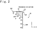
- FIG. 2 is a side view showing a structural example containing an elastic pressuring body 32 (pressuring block) that pressures the corner section CR of the object member 10 effectively in the pressure shaping.
- the bonding apparatus 8 is used when the patch 12 containing the reinforcing fiber 14 and a matrix resin is pushed and bonded to the bonded section of the corner section in the CURVE section of the object member 10.
- the bonding apparatus 8 has a bag member 20, a decompression port 21, mold releasing films 22, breathers 23, heater mats 24, sealant 26 and a pushing member 30.
- the pushing member 30 has a first cowl plate 30C, a second cowl plate 30W and the elastic pressuring body 32.
- the object member 10 has a vertically standing WEB section and a CAP section having a predetermined angle to the WEB section.
- the CURVE section (the bending section) is a section between the WEB section and the CAP section.
- the patch 12 is bonded to the bonded section of the corner section in the CURVE section.
- an angle between the WEB section and the CAP section is right-angle, but the angle between the WEB section and the CAP section is not limited to the right-angle.
- the bag member 20 is a member to cover the first cowl plate 30C, the second cowl plate 30W, the elastic pressuring body 32 and the patch 12 in the condition that the patch 12 is bonded to the bonded section in the corner section of the object member 10.
- the bag member 20 is airtight, and pushes the first cowl plate 30C, the second cowl plate 30W and the elastic pressuring body 32 to the patch 12 with the external pressure and pushes the patch 12 to the object member 10.
- the decompression port 21 is a port connecting the inside of the bag member 20 and the vacuum pump (not shown).
- the vacuum pump not shown.
- the inside of the bag member 20 is decompressed.
- the external pressure pushes the bag member 20 from outside and pushes the patch 12 to the object member 10.
- the mold releasing film 22 is a member that has peel property to the matrix resin contained in the patch 12, and is used to cover the patch 12 and the object member 10 directly.
- the breather 23 is a member to promote deaeration inside the bag member 20.
- the breather 23 is a ventilation film.
- a plurality of the breathers 23 are arranged.
- the breather 23 is arranged outside the first cowl plate 30C, the second cowl plate 30W and the elastic pressuring body 32.
- the heater mat 24 (heating unit) is equipment heating the patch 12.
- the heater mat 24 may contain a heater generating heat with the power supplied from a power supply.
- the matrix resin in the patch 12 is thermosetting resin
- the curing of the patch 12 and the adhesion to the object member 10 are carried out by the heating.
- the matrix resin of the patch 12 is a thermoplastic resin
- the patch 12 is made soften through the heating, and the curing of the patch 12 and the adhesion of the object member 10 are carried out through the cooling.
- the heater mat 24 can adopt the structure in which temperature control is carried out independently to the CAP section, the CURVE section and the WEB section. Also, in the embodiment shown in FIG.
- the heater mats 24 are arranged on both sides of the inside of the object member 10 (the -X side, the -Y side shown in FIG. 1 ) and the outside thereof (the + X side, the +Y side shown in FIG. 1 ).
- the heater mat 24 may be arranged in either of the inside or the outside of the object member 10.
- the sealant 26 is arranged between the bag member 20 and the object member 10 to secure airtightness between the outside of the bag member 20 and the inside of the bag member 20.
- the first cowl plate (a first plate section) 30C is a shaping jig to push the patch 12 to be bonded to the corner section of the object member 10 for the CAP section of the object member 10.
- the first cowl plate 30C extends from the corner pressuring section 32F to the -X direction (to the first direction). It is desirable to use a material having the property (elasticity and so on) that follows the shape of the CAP section of the object member 10 to an extent for the first cowl plate 30C.
- the second cowl plate 30W (a second plate section) is a shaping jig to push the patch 12 to be bonded to the corner section of the object member 10 for the WEB section of the object member 10.
- the second cowl plate 30W extends from the corner pressuring section 32F to the -Y direction (a second direction different from the first direction in angle). It is desirable that the second cowl plate 30W uses a material having the property (elasticity and so on) that follows the shape of the WEB section of the object member 10.
- the first cowl plate 30C and the second cowl plate 30W are arranged to have different angles along the surface shape corresponding to a corner section design value of both sides that sandwiches the corner section CR of the object member 10.
- a gap is provided at the position where the first cowl plate 30C and the second cowl plate 30W approach most in the condition shown in FIG. 2 .
- the WEB section and the CAP section have a flat plate shape but may have the surface of the curve.
- the first cowl plate 30C and the second cowl plate 30W are used which have the curved surface shape that follows the surface shape of the WEB section and the CAP section.
- the elastic pressuring body 32 is arranged on the both of the first cowl plate 30C and the second cowl plate 30W between the first cowl plate 30C and the second cowl plate 30W.
- the elastic pressuring body 32 protrudes from the gap between the first cowl plate 30C and the second cowl plate 30W so that a part of the elastic pressuring body 32 (corner pressuring section 32F) pushes the corner section CR of the object member 10.
- the elastic pressuring body 32 has a pressure receiving surface 32R where the pushing force is given, to the bag member 20 of the part between the first cowl plate 30C and the second cowl plate 30W. Also, the elastic pressuring body 32 has the corner pressuring section 32F that protrudes from the gap between the first cowl plate 30C and the second cowl plate 30W to the direction of the corner section CR of the object member 10.
- the elastic pressuring body 32 is a jig for shaping that pushes the patch 12 to the bonded section of the corner section CR of the object member 10 by using the corner pressuring section 32F.
- the elastic pressuring body 32 pushing the patch 12 diagonally with the force Fs for the corner section CR of the object member 10 it is easy to apply the force (Fs ⁇ cos ⁇ ) larger than the frictional force ⁇ Fv of the reinforcing fiber 14 to the +X direction of the reinforcing fiber 14.
- the generation of the wrinkle around the corner section CR can be decreased.
- the elastic pressuring body 32 is required to transfer the heat of the heater mat 24 to the patch 12, it is desirable that the elastic material having a high thermal conductivity is good for the elastic pressuring body 32 (such as silicone rubber, nitrile rubber, ethylene propylene rubber, chloroprene rubber, styrene butadiene rubber, polybutadiene rubber, acrylonitrile butadiene rubber, butyl rubber, urethane rubber, natural rubber and so on). Also, it is desirable to add high thermal conductivity material (for example, aluminum powder, copper powder and so on) to the elastic pressuring body 32. Especially, it is desirable to add aluminum powder to the base material of silicone rubber.
- high thermal conductivity material for example, aluminum powder, copper powder and so on
- the outward form of the corner pressuring section 32F in the side view shown in FIG. 2 may be a shape having a predetermined curvature or a shape based on a corner section design value (Nom.edge) after the patch 12 is bonded to the object member 10.
- the length of a part where the elastic pressuring body 32 and the first cowl plate 30C come into contact and the length of a part where the elastic pressuring body 32 and the second cowl plate 30W come into contact are possible to be 10 to 300 mm, respectively.
- the elastic pressuring body 32 and the first cowl plate 30C and the elastic pressuring body 32 and the second cowl plate 30W may be previously adhered together respectively.
- the elastic pressuring body 32 and the first cowl plate 30C and the elastic pressuring body 32 and the second cowl plate 30W may be arranged only without adhering them.
- a gap through which the corner pressuring section 32F passes and protrudes between the first cowl plate 30C and the second cowl plate 30W can be appropriately set in the width according to the curvature of the corner section CR.
- the first cowl plate 30C and the second cowl plate 30W may be formed from independent separate members, or may be configured (as a unitary structure) from one member that has the gap from which the elastic pressuring body 32 protrudes. Even when the first cowl plate 30C and the second cowl plate 30W are configured from one member, the shape of the WEB section and the CAP section of the object member 10 are desirable to have the elasticity due to which the first cowl plate 30C and the second cowl plate 30W follow the shape of the object member 10 according to the angle between the WEB section and the CAP section.
- the finish shape (Act.edge) of the corner section after the patch 12 is bonded to the corner section CR is approximately identical (e.g. 3.2 mm) to the corner section design value (Nom.edge) or is recessed innerwardly. Also, the generation of any wrinkle and sag is seen in the reinforcing fiber 14 inside the patch 12 shown in FIG. 1 in the CAP section (containing an improved section CB), the CURVE section, and the WEB section.
- the material of the reinforcing fiber 14 carbon fiber, glass fiber, organic fiber such as aramid fiber, polyparaphenylene benzobisoxazole fiber, phenol fiber, polyethylene fiber, polyvinyl alcohol fiber, metal fiber, ceramic fiber, or a combination of them can be used.
- the thermoplastic resin or the thermosetting resin can be used as the matrix resin to be used for the patch 12. It is desirable to use the thermosetting resin in the present situation from the aspect of the shapability and the dynamic characteristic.
- the thermosetting resin for example, epoxy, phenol, vinyl ester, unsaturated polyester, cyanate ester, bismaleimide, benzoxazine, other resin can be used.
- curing agent, curing accelerator, polymerization initiator, catalyst and so on can be added.
- the additive such as elastomer, and rubber can be used.
- thermoplastic resin for example, PPS (polyphenylene sulfide), PEEK (polyether ether ketone), PEKK (polyether ketone ketone), PEK (poly ether ketone), PI (polyimide), PEI (polyether imide), PA (nylon polyamide), and so on can be used. It is desirable to use a prepreg member in which the matrix resin is impregnated in the reinforcing fiber 14 for the patch 12, but the reinforcing fiber 14 of a dry form may be used.
- the object member 10, the bag member 20, the decompression port 21, the mold releasing film 22, the breather 23, the heater mat 24, the sealant 26 and the pushing member 30 are first prepared (see FIG. 1 ).
- the bag member 20 having the decompression port 21 is prepared.
- the pushing member 30 having the first cowl plate 30C, the second cowl plate 30W and the elastic pressuring body 32 is prepared.
- the corner pressuring section 32F of the pushing member 30 has the surface shape corresponding to the corner section design value (Nom.edge) after the patch 12 is bonded is prepared.
- a cut-out process is carried out to the bonded section of the corner section of the object member 10 according to need, to remove a damaged part, an unnecessary part for the pretreatment.
- the patch 12 containing the reinforcing fiber 14 is arranged to come into contact with the bonded section of the corner section CR of the object member 10. Then, the mold releasing film 22 is arranged on the patch 12 and the pushing member 30, the breather 23, the heater mat 24 and so on are appropriately arranged.
- the sealant 26 is arranged, and the bonded section of the object member 10, the patch 12, the mold releasing film 22, the pushing member 30, the breather 23 and the heater mat 24 are covered by the bag member 20 so as to form the closed space containing the bonded section of the object member 10.
- the vacuum pump When the closed space is formed to surround the bonded section, the vacuum pump is connected with the decompression port 21 to suck and deaerate gas in the closed space. Then, the first cowl plate 30C pushes the patch 12 for the CAP section of the object member 10 by the external pressure. In the same way, the second cowl plate 30W pushes the patch 12 for the WEB section of the object member 10. Then, the pushing force is applied to the pressure receiving surface 32R of the elastic pressuring body 32.
- the corner pressuring section 32F of the elastic pressuring body 32 protrudes from the gap between the first cowl plate 30C and the second cowl plate 30W to the direction of the corner section CR of the object member 10. Then, the corner pressuring section 32F pushes the patch 12 to the bonded section of the corner section CR of the object member 10. Because the reinforcing fiber 14 contained in the patch 12 is pulled for the corner section CR, the generation of the wrinkle in the improved section CB around the corner section CR can be decreased.
- the heater mat 24 is turned on to heat the object member 10 and the patch 12.
- a thermosetting resin is used for the matrix resin of the patch 12
- the thermosetting resin is cured in case of heating to bond the object member 10 and the patch 12 and shape them.
- a thermoplastic resin is used for the matrix resin of the patch 12
- the thermoplastic resin is cured in case of cooling after the heating to bond the object member 10 and the patch 12 and shape them.
- the bag member 20, the sealant 26, the mold releasing film 22, the pushing member 30, the breather 23 and the heater mat 24 are removed. In this way, the bonding of the patch 12 to the object member 10 is carried out.
- FIG. 3 is a side view showing the situation that a reinforcing fiber is bonded by the bonding apparatus 18 to the corner section of the object member 10 of the L-shaped-type material to carry out pressuring shape. Note that a part having the function identical with the part has been described with reference to FIG. 1 is assigned with the same reference numeral, and the description is omitted.
- the bonding apparatus 18 is used to bond the patch 12 containing the reinforcing fiber 14 and the matrix resin to the bonded section caused in the corner section of the CURVE section of the object member 10.
- the bonding apparatus 18 has the bag member 20, the decompression port 21, the mold releasing film 22, the breather 23, the heater mat 24, the sealant 26 and the pushing member 30P.
- the pressuring section 30F is formed in the corner section of the pushing member 30P.
- the pushing member 30P has a first plate section extending along the CAP section from the pressuring section 30F to the -X direction (a first direction) and a second plate section extending along the WEB section from the pressuring section 30F to the second direction different from the first direction (a -Y direction).
- the first plate section of the pushing member 30P biases the patch 12 for the CAP section of the object member 10.
- the pressuring section 30F of the pushing member 30P biases the patch 12 for the bonded section of the corner section CR of the object member 10.
- the second plate section of the pushing member 30P biases the patch 12 for the WEB section of the object member 10. It is desirable to use the material having a nature (the elasticity and so on) that follows the shape of the object member 10 for the pushing member 30P.
- the biasing unit 40 biases the pushing member 30P for the patch 12 and the bonded section of the object member 10.
- FIG. 4 is a side view showing the embodiment in which the pressuring section 42T pushes the patch 12 to the bonded section by using the clamp force FC produced by the biasing unit 40.
- FIG. 5 is a front view when the biasing unit 40 shown in FIG. 4 is observed from the -X direction.
- FIG. 6 is a cross sectional view of the biasing unit 40 shown in FIG. 5 along the B-B line.
- the biasing unit 40 has a first biasing force giving section 40I, a second biasing force giving section 40E and a biasing force giving member 42.
- the tip of the bias force giving member 42 has the pressuring section 42T.
- the biasing unit 40 has an inclination block 44, a sliding block 43 and a back block 46.
- the first biasing force giving section 40I and the second biasing force giving section 40E apply the clamp force FC to clamp the biasing force giving member 42 and the object member 10 through the sliding block 43 and the back block 46.
- the inclination block 44 shown in FIG. 4 is a triangle pillar that has the section of the right triangle. Note that right triangle includes an approximation of the right triangle.
- the surface of the inclination block 44 along the X axis and the surface thereof along the Y axis orthogonalize to each other. These two surfaces come into contact with the bonded section of the object member 10.
- the slope of the inclination block 44 (a surface inclined with respect to the X and the Y axis) is a sliding slope BV to make the sliding block 43 and the biasing force giving member 42 slide to a third direction (a direction to which the pressuring section 42T is biased for the corner section CR).
- the sliding block 43 receives the clamp force FC in the +X direction to slide to the direction of the corner section CR (the third direction) along the sliding slope BV of the inclination block 44. As a result, the clamp force FC is converted to the pressuring force FD. The pressuring force FD is communicated to the biasing force giving member 42.
- the biasing force giving member 42 receives the pressuring force FD from the inclination block 44 to slide to the direction of the corner section CR and the pressuring section 42T pushes the patch 12 to the object member 10 through the bag member 20 and so on (reference to FIG. 3 ).
- a force to the inclination direction of the sliding slope BV (the third direction) contains a component force that biases a first plate section in the pushing member 30P for the patch 12 and a component force that biases a second plate section in the pushing member 30P for the patch 12.
- the back block 46 is arranged on the back side of the object member 10 to the bonded section.
- the back block 46 receives the clamp force FC to the -X direction from the second biasing force giving section 40E to communicate the clamp force FC to the object member 10.
- the clamp force FC produced by the first biasing force giving section 40I and the second biasing force giving section 40E is converted into the pressuring force FD, that biases the patch 12 to the bonded section of the object member 10.
- the pressure shaping can be carried out.
- FIG. 5 is a diagram showing the arrangement of the object member 10 and the biasing force giving member 42 in the center section of the object member 10.
- the object member 10, the bag member 20, the decompression port 21, the mold releasing film 22, the breather 23, the heater mat 24, the sealant 26, and the pushing member 30P and the biasing unit 40 are prepared (reference to FIG. 3 to FIG. 7 ).
- the bag member 20 should be prepared to have the decompression port 21.
- the shape containing the pressuring section 30F of the pushing member 30P the object member 10 and a member having the surface shape corresponding to the corner section design value (Nom.edge) after the patch 12 is bonded.
- the removing process is carried out to the bonded section of the corner of the object member 10 as a pretreatment process according to need, to remove a damaged part or an unnecessary part.
- the patch 12 containing the reinforcing fiber 14 is arranged to come into contact with the bonded section of the corner section CR of the object member 10. Then, the mold releasing film 22 is arranged on the patch 12 and the pushing member 30P, the breather 23, the heater mat 24 and so on are appropriately arranged.
- the sealant 26 By arranging the sealant 26, the bonded section of the object member 10, the patch 12, the mold releasing film 22, the pushing member 30P, the breather 23 and the heater mat 24 are covered by the bag member 20 so as to form the closed space containing the bonded section of the object member 10.
- the vacuum pump is connected to the decompression port 21 to suck and deaerate gas in the closed space. Then, the pushing member 30P pushes the patch 12 for the CAP section and the WEB section of the object member 10 with the external pressure.
- the inclination block 44 and the biasing force giving member 42 are arranged for the object member 10 outside the closed space formed by the bag member and the object member 10.
- the pressuring section 42T is arranged to pressure the patch 12 for the corner section CR of the object member 10.
- the sliding block 43 and the back block 46 are arranged.
- the first biasing force giving section 40I and the second biasing force giving section 40E are arranged.
- the clamp force FC is applied to the sliding block 43 and the back block 46.
- the biasing force giving member 42 moves along the sliding slope BV so that the pressuring section 42T pushes the patch 12 for the corner section CR of the object member 10.
- the reinforcing fiber 14 contained in the patch 12 is pulled for the corner section CR, the generation of the wrinkle around the corner section CR can be suppressed.
- the heater mat 24 is turned on to heat the object member 10 and the patch 13.
- the biasing unit 40, the bag member 20, the sealant 26, the mold releasing film 22, the pushing member 30P, the breather 23 and the heater mat 24 are removed. In this way, the bonding of the patch 12 to the object member 10 ends.
- FIG. 7 An application example to the other object member is shown in FIG. 7 .
- the bonding of the patch 12 to the object member 10 by using the bonding apparatus according to the present invention can be applied to the manufacture and the repair of the bonded section in the corner section CR of the H-shaped material shown in FIG. 7 , in addition to the bonded sections of the L-shaped material shown in FIG. 1 and FIG. 3 , and a ⁇ character shaped material shown in FIG. 4 to FIG. 6 .
- the embodiments in which the patch 12 for repair is bonded to the bonded section of the object member 10 have been described. However, the embodiment may be used to manufacture various members or an apparatuses, by applying the patch to the object member having the bonded section.
- the bonding apparatus, a kit, a pushing member, a biasing unit and a bonding method according to the present invention have been described.
- the bonding apparatus, the kit, the pushing member, and the biasing unit and the bonding method according to the present invention are not limited to the above embodiments.
- Various changes or modifications can be carried out in the above embodiment.
- the technical matter mentioned in the above embodiment and the other technical matter mentioned in the above other embodiment can be combined.
- the present invention can be applied to an RTM (Resin Transfer Molding) method and a VaRTM (Vacuum-assisted Resin Transfer Molding) method, a double vacuum debulking method, an autoclave method, and other shaping methods.
- the pushing member is a member that pushes the patch containing a reinforcing fiber to the bonded section of the corner section of the object member.
- the pushing member may have a first plate section, a second plate section and an elastic pressuring body.
- the first plate section and the second plate section are arranged at angles different from each other along the shapes of the object member that sandwich the corner section of the object member.
- a gap is provided in the position corresponding to the corner section between the first plate section and the second plate section.
- the elastic pressuring body is arranged on the first plate section and the second plate section between the first plate section and the second plate section.
- the elastic pressuring body has the pressure receiving surface given with the pushing force between the first plate section and the second plate section on the side opposite to the gap.
- the elastic pressuring body has a pressuring section that receives the pushing force, to protrude from the gap to the direction of the corner section of the object member, so that the patch is pushed to the bonded section.
- the biasing section pushes the patch containing the reinforcing fiber to the bonded section of the corner section of the object member.
- the biasing section has a first biasing force giving section, a second biasing force giving section and a biasing force giving member.
- the biasing force giving member has a pressuring section at the tip.
- the first biasing force giving section and the second biasing force giving section apply the clamp force with which the biasing force giving member and the object member are clamped.
- the biasing force giving member extends to the direction of the corner section of the object member based on the clamp force so that the pressuring section pushes the patch to the bonded section.
- the biasing section may further include an inclination block, a sliding block and a back block.
- the inclination block, the sliding block and the biasing force giving member are arranged on the side of the bonded section of the object member and the back block is arranged on the back side of the bonded section of the object member.
- the inclination block has a sliding slope to make the sliding block and the biasing force giving member slide to a third direction.
- the sliding block converts the clamp force in the direction different from the third direction into the pressuring force in the third direction by sliding along the sliding slope, and communicates the converted force to the biasing force giving member.
- the biasing force giving section slides along the sliding slope, so that the pressuring section pushes the patch to the bonded section.
Landscapes
- Engineering & Computer Science (AREA)
- Mechanical Engineering (AREA)
- Chemical & Material Sciences (AREA)
- Composite Materials (AREA)
- Lining Or Joining Of Plastics Or The Like (AREA)
- Casting Or Compression Moulding Of Plastics Or The Like (AREA)
- Moulding By Coating Moulds (AREA)
- Folding Of Thin Sheet-Like Materials, Special Discharging Devices, And Others (AREA)
Abstract
Description
- The present invention relates to a bonding apparatus and a bonding method, that are used when a patch is bonded to the inside of a corner of an object member (hereinafter, to be referred to as a corner section) and to a concave section.
- Conventionally, Patent Literature 1 (
JP 2008-531337A - In the method of repairing the single vacuum reducing composite panel described in Patent Literature 1, a stacked layer of fiber in which an impregnation has been previously carried out with a resin is formed, the stacked layer is heated at a first temperature, and the resin is cured through the decompression. The impregnated stacked layer that has been deaerated, is arranged on the region of the composite material of the repair object. The impregnated stacked layer is heated at a second temperature, and decompressed, and the impregnated stacked layer is cured on the region of the repair object.
- Also, Patent Literature 2 (
US 2012/0080135 ) discloses a method of repairing the structure of a fuselage having a plane or a curved surface on the fuselage by a double vacuum debulking system. - The double vacuum debulking system described in
Patent Literature 2 includes an external covering bag film disposed to cover the region of the repair object, a strong bag support tool arranged between the external bag film and a parent structure; a spacer disposed to keep a constant space between the parent structure and the strong bag support tool; a first vacuum probe that is connected with a vacuum source; and a heating blanket. The shape of the strong bag support tool has the contour that coincides with the contour of the parent structure. - Also, Patent Literature 3 (
US 2008/0308210 ) discloses the invention relating to a determining process of parameters in a pretreatment process of repair composite material patch using a double vacuum bag process. - Also, Patent Literature 4 (
US 2013/0164481 ) discloses a method of repairing a damaged composite part having an exposed surface. - In a manufacturing method of a stacked layer body that is produced from polymer matrix composite material disclosed in Patent Literature 4, a peeling film is arranged on the surface of a damaged composite material, an un-curing stack assembly is formed to conform to the contour of the surface of the damaged composite material, and heating at a temperature below a curing temperature while sucking. After that, the un-curing stack assembly is removed, adhesive material is applied on the exposed surface of the damaged composite material and then the un-cured stack assembly is arranged again, and the stack assembly is cured while compressing.
-
- [Patent Literature 1]
JP 2008-531337A - [Patent Literature 2]
US 2012/0080135 - [Patent Literature 3]
US 2008/0308210 - [Patent Literature 4]
US 2013/0164481 - According to the method of repairing the composite material described in Patent Literatures 1-4, the repair is possible to add a reinforcing fiber to a surface and a convex section of the repair object member. However, when applying the repairing method of the composite material described in Patent Literatures 1-4 is applied to an application in which the reinforcing fiber is added to a corner section and a concave section of the repair object member, the strength of the structure material is sometimes declined after the repairing.
- The present invention has as an object, to provide a bonding apparatus and a bonding method, in which a patch containing a reinforcing fiber is bonded to the corner section and the concave section of the object member.
- The bonding apparatus that bonds a patch containing a reinforcing fiber, to a bonded section on a surface portion of a corner section of an object member. The bonding apparatus includes: a pushing member and a biasing section. The pushing member is disposed to push a surface of the bonded patch in response to an application force. The biasing section is disposed to give the application force to the pushing member.
- The pushing member includes: a first plate section disposed to extend along the object member from the corner section to a first direction; and a second plate section disposed to extend along the object member from the corner section to a second direction different from the first direction. The object member is pushed with the first plate section and the second plate section in response to the application force.
- The pushing member includes: a first plate section disposed to extend along the object member from the corner section to a first direction; a second plate section disposed to extend along the object member from the corner section to a second direction different from the first direction; and an elastic pressuring body disposed to push the corner section through a gap between the first plate section and the second plate section. The elastic pressuring body has a pressure receiving surface to which the application force is given, and a pressuring section that pushes the corner section through the gap between the first plate section and the second plate section in response to the application force.
- The elastic pressuring body has Durometer hardness in a range of 10 to 55.
- The elastic pressuring body is added with a high thermal transmission material.
- The bonding apparatus further includes: a heating unit disposed to heat the patch; and a bag member disposed to cover the surface portion containing the bonded section of the object member, the patch, the heating unit, and the pushing member. The application force can use an atmosphere pressure that acts to the pressure receiving surface through the bag member.
- The bonding apparatus further includes: a heating unit disposed to heat the patch; and a bag member disposed to cover the surface portion containing the bonded section of the object member, the patch, the heating unit and pushing member. The inside of the bag member is decompressed. The biasing section is arranged outside a closed space formed from the bag member and the object member to bias the pushing member for the patch.
- The biasing section has a bias force giving member that applies pressuring force along a third direction. The third direction is a direction to which the pressuring section biased for the corner section and a component force to the third direction includes a component force of a direction to bias a first plate section for the patch and a component force of the direction to bias a second plate section for the patch.
- The biasing section further includes an inclination block and a sliding block. The inclination block has a sliding slope to make the sliding block and the giving member slide to a third direction along the sliding slope. The sliding block slides along the sliding slope to convert a clamp force in a direction different from a third direction to the application force in the third direction to transfer to the biasing force giving member. The biasing force giving member applies the pressuring force to the pushing member through the bag member by sliding along the sliding slope.
- The inclination block, the sliding block and the giving member are arranged on a side of the bonded section of the object member. The biasing section further comprises a back block arranged on a back side of the bonded section of the object member to apply the clamp force.
- A bonding method using the bonding apparatus according to the present invention is a method of bonding a patch containing a reinforcing fiber to a bonded section of a surface portion in a corner section of an object member. The bonding method of the present invention includes preparing a bag member having a decompression port, a heating unit and a pushing member pushing a surface of the patch; arranging the patch in the bonded section of the corner section of the object member; disposing the pushing member toward the bonded section of the corner section; arranging the pushing member for the pressuring section to come into contact with the bonded section of the corner section; and forming a closed space from the bag member and the object member, such that the patch, the heating unit, and the pushing member are arranged in the closed space.
- Also, through the decompression port, the bonding method includes deaerating gas in the closed space and pushing the pressuring section of the pushing member for the corner section through the patch. The object member and the patch are heated and bonded by a heating unit.
- The pushing member according to the present invention is a member pushing a patch containing a reinforcing fiber to a bonded section in a corner section of an object member. The pushing member has a first plate section, a second plate section and an elastic pressuring body. The first plate section and the second plate section are arranged on both sides of put the corner section of the object member between plate sections at angles different from each other and a gap corresponding to the corner section is provided between the first plate section and the second plate section.
- The elastic pressuring body is arranged to extend over the first plate section and the second plate section between the first plate section and the second plate section. Also, the elastic pressuring body has a pressure receiving surface to which the pushing force is given, on an opposite side to the gap. The elastic pressuring body has a pressuring section receiving the pushing force and protrudes from the gap to the direction of the corner section of the object member, to push the patch to the bonded section.
- A biasing section according to the present invention pushes a patch containing a reinforcing fiber to a bonded section in a corner section of an object member. The biasing section has a first biasing force giving section, a second biasing force giving section and a biasing force giving member. The biasing force giving member has a pressuring section at the tip. The first biasing force giving section and the second biasing force giving section apply a clamp force to clamp the biasing force giving member and the object member. Then, the biasing force giving member extends to the direction of the corner section of the object member based on the clamp force, so that the pressuring section pushes the patch to the bonded section.
- A biasing unit of the present invention includes an inclination block, a sliding block and a back block. The inclination block, the sliding block and a biasing force giving member are arranged on the side of the bonded section of the object member. The back block is arranged on the back side of the bonded section of the object member. The inclination block has a sliding slope to make the sliding block and the biasing force giving member slide for a third direction. The sliding block slides along the sliding slope, to convert a clamp force in a direction different from the third direction into the pressuring force to the third direction, to communicate to the biasing force giving member. The biasing force giving member slides along the sliding slope so that the pressuring section pushes the patch to the bonded section.
- By using the bonding apparatus, the kit, the pushing member, the the biasing unit and the bonding method according to the present invention, the patch containing the reinforcing fiber can be effectively pushed to the corner section and the concave section of the object member and the generation of a wrinkle can be decreased.
-
- [
FIG. 1 ]
FIG. 1 is a side view showing the situation that pressure shaping is carried out by bonding a reinforcing fiber to a corner section of an object member of an L-shaped material by a bonding apparatus according to an embodiment. - [
FIG. 2 ]
FIG. 2 is a side view showing a structural example in which an elastic pressuring body effectively pushes the corner section of the object member in the pressure shaping. - [
FIG. 3 ]
FIG. 3 is a side view showing the situation that the pressure shaping is carried out by bonding the reinforcing fiber to the corner section of the object member of the L-shaped material by the bonding apparatus according to an embodiment. - [
FIG. 4 ]
FIG. 4 is a side view showing that a pressuring section pushes a patch to a bonded section by using clamp force generated by a biasing section in the embodiment. - [
FIG. 5 ]
FIG. 5 is a front view showing an observation result of the the biasing section shown inFIG. 4 from a -X direction. - [
FIG. 6 ]
FIG. 6 is a sectional view showing the biasing section along the B-B arrow line shown inFIG. 5 . - [
FIG. 7 ]
FIG. 7 is a diagram showing the shape of another object member to which the bonding apparatus of the embodiment can be applied. - [
FIG. 8 ]
FIG. 8 is a side view showing the situation that the pressure shaping is carried out by bonding the reinforcing fiber to the corner section of the object member of the L-shaped material. - The subject matter recognized about the techniques known to the inventors of the present invention will be described with reference to
FIG. 8. FIG. 8 is a side view showing the situation that a reinforcing fiber is bonded to a corner section of an L-shapedobject member 10 as a target by abonding apparatus 908. - Referring to
FIG. 8 , thebonding apparatus 908 is used when apatch 12 containing reinforcingfiber 14 and a matrix resin is bonded to a bonded section at a corner section CR of a CURVE section (bent section) of anobject member 10. - The
bonding apparatus 908 has abag member 20, adecompression port 21, amold releasing film 22, abreather 23, aheater mat 24 and asealant 26. Theobject member 10 has a standing WEB section (a section extending to one direction from the bent section in an example shown inFIG. 8 ) and a CAP section (a section extending to another direction from the bent section and a vertex section in an example shown inFIG. 8 ) that has a predetermined angle to the WEB section. The CURVE section is a section between the WEB section and the CAP section. - The
bag member 20 is the member that covers thepatch 12 from the outside in the condition that thepatch 12 is arranged to the bonded section of the corner section of theobject member 10 and has airtightness. Thebag member 20 pushes thepatch 12 to theobject member 10 by using an external pressure (e.g. atmosphere pressure). - The
decompression port 21 is used to connect the inside of thebag member 20 and a vacuum pump (not shown). A gas existing in a closed space inside thebag member 20 is evacuated through thedecompression port 21, and the inside of thebag member 20 is decompressed. Thus, the external pressure pushes thebag member 20 from outside so as to push thepatch 12 to theobject member 10. - The
mold releasing film 22 having a peel property to the matrix resin is contained in thepatch 12, and so on and is used to cover thepatch 12 and theobject member 10 directly. - The
breather 23 is a member to promote deaeration inside thebag member 20. For example, thebreather 23 is a breathable film. - The
heater mat 24 is a device to heat thepatch 12. When the matrix resin of thepatch 12 is a thermosetting resin, the curing of thepatch 12 and adhesion to theobject member 10 are carried out through the heating. Theheater mat 24 may contain a heater generating heat with power from a power supply. - The
sealant 26 is arranged between thebag member 20 and theobject member 10 to secure airtightness between the outside of thebag member 20 and the inside of thebag member 20. - Next, a method of bonding the
patch 12 to the bonded section in the corner section of theobject member 10 will be described. - First, a cutting-out process is carried out according to need to the bonded section of the
object member 10 to remove a damage part and so on. - Next, the
patch 12 containing the reinforcingfiber 14 is arranged on the surface of the bonded section of theobject member 10. Then, themold releasing film 22, thebreather 23, theheater mat 24 and thebreather 23 are arranged in this order on the surface of thepatch 12 and theobject member 10. Then, thesealant 26 is arranged and thedecompression port 21 and the vacuum pump are connected, and then the inside of thebag member 20 is decompressed and deaerated. Note that when the reinforcingfiber 14 of a dry form type of thepatch 12 is used, the matrix resin may be applied to the dry form previously, or, the matrix resin may be injected inside thebag member 20 while decompressing the inside of thebag member 20. Thus, the matrix resin can be impregnated into the reinforcingfiber 14. - Next, power is supplied to the
heater mat 24 so as to heat thepatch 12 and theobject member 10. After the heating is carried out for a predetermined time, the inside of thebag member 20 is returned to the external pressure after cooling, and thebag member 20, themold releasing film 22, thebreather 23 and theheater mat 24 are removed from theobject member 10. - As a result of experiments to bond the
patch 12 to theobject member 10 by using thebonding apparatus 908 shown inFIG. 8 , there is a phenomenon that the patch is cured in the condition protruding from a corner section design value (Nom.edge) in a final shape (Act.edge) of an end of the corner section after thepatch 12 is bonded. - Also, as shown in
FIG. 8 , a phenomenon was seen in which a wrinkle and sag are caused in the reinforcingfiber 14 of the CURVE section and the CAP section of theobject member 10. Especially, it is easy for the wrinkle to generate in the wrinkle generation section FW of the CAP section. - On the other hand, when the
patch 12 is bonded to a flat plate not having the CURVE section as shown inFIG. 8 , the generation of any wrinkle was not seen even if thepatch 12 was bonded in the same condition. From this, it is concluded that any wrinkle is easy to generate at a wrinkle generation section FW shown inFIG. 8 in the CURVE section of theobject member 10 and around it. Especially, it is concluded that a generation frequency is high in the CAP section in the neighborhood of the CURVE section. - Especially, in the embodiment shown in
FIG. 8 , there is a tendency that the wrinkle is easy to generate in the CAP section (the wrinkle generation section FW) which is in a side direction of the corner section CR where thepatch 12 is easy to hang with the weight. When theobject member 10 is a single article of a small channel member, it is possible to try to reduce the generation of the wrinkle by changing the relation of the direction of of the bonded section and the direction of the weight by changing the attitude of the object member 10 (turned and so on). However, in case where the structural section of an aircraft parked in an apron is repaired, it is very difficult to change the relation of the direction of the weight and the direction of the bonded section. - The reason why the generation frequency of the wrinkle is high in the wrinkle generation section FW shown in
FIG. 8 is in that the reinforcingfiber 14 of thepatch 12 is difficult to slide near the wrinkle generation section FW. It is considered that a wrinkle caused in the reinforcingfiber 14 does not stretched because the reinforcingfiber 14 is difficult to slide, and the reinforcingfiber 14 is cured in the condition that sag is caused so that the wrinkle is caused in the reinforcingfiber 14. - As a cause that the reinforcing
fiber 14 of thepatch 12 is difficult to slide smoothly in the wrinkle generation section FW, it is considered that the reinforcingfiber 14 is pushed with a force Fv(N) in a perpendicular direction (+Y direction shown inFIG. 8 ) to the CAP section by decompressing the inside of thebag member 20, so that a frictional force µFv(N) is generated between the reinforcingfiber 14 and theobject member 10. The reinforcingfiber 14 is difficult to slide to the X direction shows inFIG. 8 due to the frictional force µFv. As a result, a wrinkle is left in the wrinkle generation section FW so that the wrinkle becomes easy to generate. - On the other hand, the force to prevent the generation of the wrinkle when the reinforcing
fiber 14 of thepatch 12 is slid to the X direction shown inFIG. 8 in the CAP section is generated from a +X component (Fs×cos θ) of a force Fs(N) pushing the corner section CR to a diagonal direction between the +X direction and the +Y direction (for example, angle θ=45° to the X direction). The force Fs pushing to the diagonal direction is obtained from the pushing force applied to the surface of thebag member 20 by decompressing the inside of thebag member 20. However, it can be considered that the force Fs pushing in the diagonal direction reduces due to the frictional force among thebag member 20, themold releasing film 22 and theheater mat 24. Therefore, it can be considered that the pushing force in the +X direction to the reinforcingfiber 14 of thepatch 12 is lacking at the wrinkle generation section FW so that the reinforcingfiber 14 is cured without extending the wrinkle and the wrinkle becomes easy to generate. - In this case, for example, when the length in the X direction of the CAP section of the
patch 12 is X=2.54(cm), the length in the depth direction shown inFIG. 8 is Z=20(cm), the friction coefficient between the reinforcingfibers 14 is µ=0.3, and the external pressure (the atmosphere pressure) P=0.1013(MPa) is applied to thebag member 20, it is possible to expect that the generation of the wrinkle can be prevented in some degree if the force Fs pushing diagonally is Fs ≥ 222(N). Therefore, considering the margin of 1.5 times, an experiment was carried out in which the pushing force of 350(N) from the outside of thebag member 20 is applied to the diagonal direction in the +X direction and the +Y direction (angle θ = 45° to the X direction) of the corner section CR to bond thepatch 12. As the result of this experiment, the generation of the wrinkle was not seen in the reinforcingfiber 14 of thepatch 12 in either of the CAP section, the CURVE section and the WEB section. - Referring to the attached drawings, the bonding apparatus according to an embodiment of the present invention will be described below.
FIG. 1 is a side view showing the situation when a reinforcing fiber is bonded to the corner section of the L-shaped material as theobject member 10 and is subjected to pressure shaping by using the bonding apparatus 8.FIG. 2 is a side view showing a structural example containing an elastic pressuring body 32 (pressuring block) that pressures the corner section CR of theobject member 10 effectively in the pressure shaping. - Referring to
FIG. 1 , the bonding apparatus 8 according to the first embodiment of the present invention is used when thepatch 12 containing the reinforcingfiber 14 and a matrix resin is pushed and bonded to the bonded section of the corner section in the CURVE section of theobject member 10. The bonding apparatus 8 has abag member 20, adecompression port 21,mold releasing films 22,breathers 23,heater mats 24,sealant 26 and a pushingmember 30. Referring toFIG. 2 , the pushingmember 30 has afirst cowl plate 30C, asecond cowl plate 30W and theelastic pressuring body 32. - For example, the
object member 10 has a vertically standing WEB section and a CAP section having a predetermined angle to the WEB section. The CURVE section (the bending section) is a section between the WEB section and the CAP section. Thepatch 12 is bonded to the bonded section of the corner section in the CURVE section. - Note that in an embodiment shown in
FIG. 1 , an angle between the WEB section and the CAP section is right-angle, but the angle between the WEB section and the CAP section is not limited to the right-angle. - The
bag member 20 is a member to cover thefirst cowl plate 30C, thesecond cowl plate 30W, theelastic pressuring body 32 and thepatch 12 in the condition that thepatch 12 is bonded to the bonded section in the corner section of theobject member 10. Thebag member 20 is airtight, and pushes thefirst cowl plate 30C, thesecond cowl plate 30W and theelastic pressuring body 32 to thepatch 12 with the external pressure and pushes thepatch 12 to theobject member 10. - The
decompression port 21 is a port connecting the inside of thebag member 20 and the vacuum pump (not shown). When the gas existing in a closed space inside thebag member 20 is deaerated through thedecompression port 21, the inside of thebag member 20 is decompressed. Thus, the external pressure pushes thebag member 20 from outside and pushes thepatch 12 to theobject member 10. - The
mold releasing film 22 is a member that has peel property to the matrix resin contained in thepatch 12, and is used to cover thepatch 12 and theobject member 10 directly. - The
breather 23 is a member to promote deaeration inside thebag member 20. For example, thebreather 23 is a ventilation film. In the embodiment shown inFIG. 1 , a plurality of thebreathers 23 are arranged. Thebreather 23 is arranged outside thefirst cowl plate 30C, thesecond cowl plate 30W and theelastic pressuring body 32. - The heater mat 24 (heating unit) is equipment heating the
patch 12. Theheater mat 24 may contain a heater generating heat with the power supplied from a power supply. When the matrix resin in thepatch 12 is thermosetting resin, the curing of thepatch 12 and the adhesion to theobject member 10 are carried out by the heating. Note that when the matrix resin of thepatch 12 is a thermoplastic resin, thepatch 12 is made soften through the heating, and the curing of thepatch 12 and the adhesion of theobject member 10 are carried out through the cooling. Theheater mat 24 can adopt the structure in which temperature control is carried out independently to the CAP section, the CURVE section and the WEB section. Also, in the embodiment shown inFIG. 1 , it is shown in the embodiment that theheater mats 24 are arranged on both sides of the inside of the object member 10 (the -X side, the -Y side shown inFIG. 1 ) and the outside thereof (the + X side, the +Y side shown inFIG. 1 ). However, according to the heating situation of thepatch 12, theheater mat 24 may be arranged in either of the inside or the outside of theobject member 10. - The
sealant 26 is arranged between thebag member 20 and theobject member 10 to secure airtightness between the outside of thebag member 20 and the inside of thebag member 20. - Referring to
FIG. 1 andFIG. 2 , the first cowl plate (a first plate section) 30C is a shaping jig to push thepatch 12 to be bonded to the corner section of theobject member 10 for the CAP section of theobject member 10. Thefirst cowl plate 30C extends from thecorner pressuring section 32F to the -X direction (to the first direction). It is desirable to use a material having the property (elasticity and so on) that follows the shape of the CAP section of theobject member 10 to an extent for thefirst cowl plate 30C. - The
second cowl plate 30W (a second plate section) is a shaping jig to push thepatch 12 to be bonded to the corner section of theobject member 10 for the WEB section of theobject member 10. Thesecond cowl plate 30W extends from thecorner pressuring section 32F to the -Y direction (a second direction different from the first direction in angle). It is desirable that thesecond cowl plate 30W uses a material having the property (elasticity and so on) that follows the shape of the WEB section of theobject member 10. - The
first cowl plate 30C and thesecond cowl plate 30W are arranged to have different angles along the surface shape corresponding to a corner section design value of both sides that sandwiches the corner section CR of theobject member 10. A gap is provided at the position where thefirst cowl plate 30C and thesecond cowl plate 30W approach most in the condition shown inFIG. 2 . - In the embodiment shown in
FIG. 1 , the WEB section and the CAP section have a flat plate shape but may have the surface of the curve. In this case, thefirst cowl plate 30C and thesecond cowl plate 30W are used which have the curved surface shape that follows the surface shape of the WEB section and the CAP section. - The
elastic pressuring body 32 is arranged on the both of thefirst cowl plate 30C and thesecond cowl plate 30W between thefirst cowl plate 30C and thesecond cowl plate 30W. Theelastic pressuring body 32 protrudes from the gap between thefirst cowl plate 30C and thesecond cowl plate 30W so that a part of the elastic pressuring body 32 (corner pressuring section 32F) pushes the corner section CR of theobject member 10. - The
elastic pressuring body 32 has apressure receiving surface 32R where the pushing force is given, to thebag member 20 of the part between thefirst cowl plate 30C and thesecond cowl plate 30W. Also, theelastic pressuring body 32 has thecorner pressuring section 32F that protrudes from the gap between thefirst cowl plate 30C and thesecond cowl plate 30W to the direction of the corner section CR of theobject member 10. Theelastic pressuring body 32 is a jig for shaping that pushes thepatch 12 to the bonded section of the corner section CR of theobject member 10 by using thecorner pressuring section 32F. - In the condition shown in
FIG. 1 , when the inside of thebag member 20 is deaerated and sucked, the outer surface of thebag member 20 is pushed to the direction of theobject member 10 by the external pressure. At that time, the pushing force is applied to thepressure receiving surface 32R of theelastic pressuring body 32 through thebreather 23 and theheater mat 24. Because theelastic pressuring body 32 has elasticity, a part of theelastic pressuring body 32 that is arranged in the range between thefirst cowl plate 30C and thesecond cowl plate 30W (thecorner pressuring section 32F) protrudes from the gap between thefirst cowl plate 30C and thesecond cowl plate 30W to the direction of the corner section CR of theobject member 10 with the pushing force given to thepressure receiving surface 32R. - The
corner pressuring section 32F that protrudes from the gap between thefirst cowl plate 30C and thesecond cowl plate 30W pushes thepatch 12 to the bonded section of the corner section CR of theobject member 10 in case of curing thepatch 12. By theelastic pressuring body 32 pushing thepatch 12 diagonally with the force Fs for the corner section CR of theobject member 10, it is easy to apply the force (Fs×cos θ) larger than the frictional force µFv of the reinforcingfiber 14 to the +X direction of the reinforcingfiber 14. By sliding the reinforcingfiber 14 to the +X direction shown inFIG. 1 , the generation of the wrinkle around the corner section CR can be decreased. - It is desirable to use the material that has the characteristic of protruding from the gap between the
first cowl plate 30C and thesecond cowl plate 30W with the pushing force given from thepressure receiving surface 32R as the material of theelastic pressuring body 32. Therefore, it is desirable to use the material having the Durometer hardness in a range of 10 to 55 for theelastic pressuring body 32. Also, because theelastic pressuring body 32 is required to transfer the heat of theheater mat 24 to thepatch 12, it is desirable that the elastic material having a high thermal conductivity is good for the elastic pressuring body 32 (such as silicone rubber, nitrile rubber, ethylene propylene rubber, chloroprene rubber, styrene butadiene rubber, polybutadiene rubber, acrylonitrile butadiene rubber, butyl rubber, urethane rubber, natural rubber and so on). Also, it is desirable to add high thermal conductivity material (for example, aluminum powder, copper powder and so on) to theelastic pressuring body 32. Especially, it is desirable to add aluminum powder to the base material of silicone rubber. - The outward form of the
corner pressuring section 32F in the side view shown inFIG. 2 may be a shape having a predetermined curvature or a shape based on a corner section design value (Nom.edge) after thepatch 12 is bonded to theobject member 10. - Also, in the side views shown in
FIG. 1 andFIG. 2 , the length of a part where theelastic pressuring body 32 and thefirst cowl plate 30C come into contact and the length of a part where theelastic pressuring body 32 and thesecond cowl plate 30W come into contact are possible to be 10 to 300 mm, respectively. Theelastic pressuring body 32 and thefirst cowl plate 30C and theelastic pressuring body 32 and thesecond cowl plate 30W may be previously adhered together respectively. Also, theelastic pressuring body 32 and thefirst cowl plate 30C and theelastic pressuring body 32 and thesecond cowl plate 30W may be arranged only without adhering them. A gap through which thecorner pressuring section 32F passes and protrudes between thefirst cowl plate 30C and thesecond cowl plate 30W can be appropriately set in the width according to the curvature of the corner section CR. - The
first cowl plate 30C and thesecond cowl plate 30W may be formed from independent separate members, or may be configured (as a unitary structure) from one member that has the gap from which theelastic pressuring body 32 protrudes. Even when thefirst cowl plate 30C and thesecond cowl plate 30W are configured from one member, the shape of the WEB section and the CAP section of theobject member 10 are desirable to have the elasticity due to which thefirst cowl plate 30C and thesecond cowl plate 30W follow the shape of theobject member 10 according to the angle between the WEB section and the CAP section. - As a result that the experiment is carried out to bond the
patch 12 and theobject member 10 by using the bonding apparatus 8 shown inFIG. 1 , the finish shape (Act.edge) of the corner section after thepatch 12 is bonded to the corner section CR is approximately identical (e.g. 3.2 mm) to the corner section design value (Nom.edge) or is recessed innerwardly. Also, the generation of any wrinkle and sag is seen in the reinforcingfiber 14 inside thepatch 12 shown inFIG. 1 in the CAP section (containing an improved section CB), the CURVE section, and the WEB section. From this fact, it can be determined that thepressure receiving surface 32R is pushed by the external pressure of thebag member 20 so that the part of theelastic pressuring body 32 protrudes from the gap between thefirst cowl plate 30C and thesecond cowl plate 30W to push the corner section CR of theobject member 10 effectively. - Note that as the material of the reinforcing
fiber 14, carbon fiber, glass fiber, organic fiber such as aramid fiber, polyparaphenylene benzobisoxazole fiber, phenol fiber, polyethylene fiber, polyvinyl alcohol fiber, metal fiber, ceramic fiber, or a combination of them can be used. - Also, as the matrix resin to be used for the
patch 12, the thermoplastic resin or the thermosetting resin can be used. It is desirable to use the thermosetting resin in the present situation from the aspect of the shapability and the dynamic characteristic. As the thermosetting resin, for example, epoxy, phenol, vinyl ester, unsaturated polyester, cyanate ester, bismaleimide, benzoxazine, other resin can be used. To cure, curing agent, curing accelerator, polymerization initiator, catalyst and so on can be added. Moreover, the additive such as elastomer, and rubber can be used. - Also, as the thermoplastic resin, for example, PPS (polyphenylene sulfide), PEEK (polyether ether ketone), PEKK (polyether ketone ketone), PEK (poly ether ketone), PI (polyimide), PEI (polyether imide), PA (nylon polyamide), and so on can be used. It is desirable to use a prepreg member in which the matrix resin is impregnated in the reinforcing
fiber 14 for thepatch 12, but the reinforcingfiber 14 of a dry form may be used. - The method of bonding the
patch 12 containing the reinforcingfiber 14, to theobject member 10 to have the bonded section in the corner section CR by the bonding apparatus 8 will be described. - The
object member 10, thebag member 20, thedecompression port 21, themold releasing film 22, thebreather 23, theheater mat 24, thesealant 26 and the pushingmember 30 are first prepared (seeFIG. 1 ). Thebag member 20 having thedecompression port 21 is prepared. The pushingmember 30 having thefirst cowl plate 30C, thesecond cowl plate 30W and theelastic pressuring body 32 is prepared. Also, thecorner pressuring section 32F of the pushingmember 30 has the surface shape corresponding to the corner section design value (Nom.edge) after thepatch 12 is bonded is prepared. - Next, a cut-out process is carried out to the bonded section of the corner section of the
object member 10 according to need, to remove a damaged part, an unnecessary part for the pretreatment. - Next, the
patch 12 containing the reinforcingfiber 14 is arranged to come into contact with the bonded section of the corner section CR of theobject member 10. Then, themold releasing film 22 is arranged on thepatch 12 and the pushingmember 30, thebreather 23, theheater mat 24 and so on are appropriately arranged. - The
sealant 26 is arranged, and the bonded section of theobject member 10, thepatch 12, themold releasing film 22, the pushingmember 30, thebreather 23 and theheater mat 24 are covered by thebag member 20 so as to form the closed space containing the bonded section of theobject member 10. - When the closed space is formed to surround the bonded section, the vacuum pump is connected with the
decompression port 21 to suck and deaerate gas in the closed space. Then, thefirst cowl plate 30C pushes thepatch 12 for the CAP section of theobject member 10 by the external pressure. In the same way, thesecond cowl plate 30W pushes thepatch 12 for the WEB section of theobject member 10. Then, the pushing force is applied to thepressure receiving surface 32R of theelastic pressuring body 32. - When the pushing force is applied to the
pressure receiving surface 32R of theelastic pressuring body 32, thecorner pressuring section 32F of theelastic pressuring body 32 protrudes from the gap between thefirst cowl plate 30C and thesecond cowl plate 30W to the direction of the corner section CR of theobject member 10. Then, thecorner pressuring section 32F pushes thepatch 12 to the bonded section of the corner section CR of theobject member 10. Because the reinforcingfiber 14 contained in thepatch 12 is pulled for the corner section CR, the generation of the wrinkle in the improved section CB around the corner section CR can be decreased. - During a predetermined time, the
heater mat 24 is turned on to heat theobject member 10 and thepatch 12. When a thermosetting resin is used for the matrix resin of thepatch 12, the thermosetting resin is cured in case of heating to bond theobject member 10 and thepatch 12 and shape them. When a thermoplastic resin is used for the matrix resin of thepatch 12, the thermoplastic resin is cured in case of cooling after the heating to bond theobject member 10 and thepatch 12 and shape them. - If the shaping ends, the
bag member 20, thesealant 26, themold releasing film 22, the pushingmember 30, thebreather 23 and theheater mat 24 are removed. In this way, the bonding of thepatch 12 to theobject member 10 is carried out. - In the first embodiment, the embodiment in which the corner section CR of the
object member 10 is pushed using theelastic pressuring body 32 has been described. On the other hand, in a second embodiment, an embodiment in which the corner section CR of theobject member 10 is pushed by using apressuring section 30F that is formed in a corner section of the pushingmember 30P will be described. -
FIG. 3 is a side view showing the situation that a reinforcing fiber is bonded by thebonding apparatus 18 to the corner section of theobject member 10 of the L-shaped-type material to carry out pressuring shape. Note that a part having the function identical with the part has been described with reference toFIG. 1 is assigned with the same reference numeral, and the description is omitted. - Referring to
FIG. 3 , thebonding apparatus 18 is used to bond thepatch 12 containing the reinforcingfiber 14 and the matrix resin to the bonded section caused in the corner section of the CURVE section of theobject member 10. Thebonding apparatus 18 has thebag member 20, thedecompression port 21, themold releasing film 22, thebreather 23, theheater mat 24, thesealant 26 and the pushingmember 30P. - As shown in
FIG. 3 , thepressuring section 30F is formed in the corner section of the pushingmember 30P. The pushingmember 30P has a first plate section extending along the CAP section from thepressuring section 30F to the -X direction (a first direction) and a second plate section extending along the WEB section from thepressuring section 30F to the second direction different from the first direction (a -Y direction). - The first plate section of the pushing
member 30P biases thepatch 12 for the CAP section of theobject member 10. Thepressuring section 30F of the pushingmember 30P biases thepatch 12 for the bonded section of the corner section CR of theobject member 10. The second plate section of the pushingmember 30P biases thepatch 12 for the WEB section of theobject member 10. It is desirable to use the material having a nature (the elasticity and so on) that follows the shape of theobject member 10 for the pushingmember 30P. - Next, with reference to
FIG. 4 to FIG. 6 , the embodiment in which the pressure shaping of the pushingmember 30P shown inFIG. 3 is carried out by using thebiasing unit 40 in addition to the external pressure to thebag member 20 will be described. The biasingunit 40 biases the pushingmember 30P for thepatch 12 and the bonded section of theobject member 10. -
FIG. 4 is a side view showing the embodiment in which thepressuring section 42T pushes thepatch 12 to the bonded section by using the clamp force FC produced by the biasingunit 40.FIG. 5 is a front view when the biasingunit 40 shown inFIG. 4 is observed from the -X direction.FIG. 6 is a cross sectional view of the biasingunit 40 shown inFIG. 5 along the B-B line. - As shown in
FIG. 4 to FIG. 6 , the biasingunit 40 has a first biasing force giving section 40I, a second biasingforce giving section 40E and a biasingforce giving member 42. The tip of the biasforce giving member 42 has thepressuring section 42T. Also, the biasingunit 40 has aninclination block 44, a slidingblock 43 and aback block 46. - The first biasing force giving section 40I and the second biasing
force giving section 40E apply the clamp force FC to clamp the biasingforce giving member 42 and theobject member 10 through the slidingblock 43 and theback block 46. - The
inclination block 44 shown inFIG. 4 is a triangle pillar that has the section of the right triangle. Note that right triangle includes an approximation of the right triangle. The surface of theinclination block 44 along the X axis and the surface thereof along the Y axis orthogonalize to each other. These two surfaces come into contact with the bonded section of theobject member 10. The slope of the inclination block 44 (a surface inclined with respect to the X and the Y axis) is a sliding slope BV to make the slidingblock 43 and the biasingforce giving member 42 slide to a third direction (a direction to which thepressuring section 42T is biased for the corner section CR). - The sliding
block 43 receives the clamp force FC in the +X direction to slide to the direction of the corner section CR (the third direction) along the sliding slope BV of theinclination block 44. As a result, the clamp force FC is converted to the pressuring force FD. The pressuring force FD is communicated to the biasingforce giving member 42. - The biasing
force giving member 42 receives the pressuring force FD from theinclination block 44 to slide to the direction of the corner section CR and thepressuring section 42T pushes thepatch 12 to theobject member 10 through thebag member 20 and so on (reference toFIG. 3 ). Note that a force to the inclination direction of the sliding slope BV (the third direction) contains a component force that biases a first plate section in the pushingmember 30P for thepatch 12 and a component force that biases a second plate section in the pushingmember 30P for thepatch 12. - The
back block 46 is arranged on the back side of theobject member 10 to the bonded section. Theback block 46 receives the clamp force FC to the -X direction from the second biasingforce giving section 40E to communicate the clamp force FC to theobject member 10. - The clamp force FC produced by the first biasing force giving section 40I and the second biasing
force giving section 40E is converted into the pressuring force FD, that biases thepatch 12 to the bonded section of theobject member 10. Thus, the pressure shaping can be carried out. - As shown in the embodiment of
FIG. 5 , when theobject member 10 is long in a longitudinal direction, the first biasing force giving section 40I, the second biasingforce giving section 40E, the slidingblock 43, theinclination block 44 of the biasingunit 40 are arranged in either end of theobject member 10, and the pressuring force FD can be applied to the direction of the corner section CR of theobject member 10 by using the biasingforce giving member 42. Note thatFIG. 6 is a diagram showing the arrangement of theobject member 10 and the biasingforce giving member 42 in the center section of theobject member 10. - Next, a method of bonding the
patch 12 containing the reinforcingfiber 14 to theobject member 10 having the bonded section of the corner section CR, by thebonding apparatus 18 and the biasingunit 40 will be described. - First, the
object member 10, thebag member 20, thedecompression port 21, themold releasing film 22, thebreather 23, theheater mat 24, thesealant 26, and the pushingmember 30P and the biasingunit 40 are prepared (reference toFIG. 3 to FIG. 7 ). Thebag member 20 should be prepared to have thedecompression port 21. As the shape containing thepressuring section 30F of the pushingmember 30P, theobject member 10 and a member having the surface shape corresponding to the corner section design value (Nom.edge) after thepatch 12 is bonded. - Next, the removing process is carried out to the bonded section of the corner of the
object member 10 as a pretreatment process according to need, to remove a damaged part or an unnecessary part. - Next, as shown in
FIG. 3 , thepatch 12 containing the reinforcingfiber 14 is arranged to come into contact with the bonded section of the corner section CR of theobject member 10. Then, themold releasing film 22 is arranged on thepatch 12 and the pushingmember 30P, thebreather 23, theheater mat 24 and so on are appropriately arranged. - By arranging the
sealant 26, the bonded section of theobject member 10, thepatch 12, themold releasing film 22, the pushingmember 30P, thebreather 23 and theheater mat 24 are covered by thebag member 20 so as to form the closed space containing the bonded section of theobject member 10. - After the closed space is formed to surround the bonded section, the vacuum pump is connected to the
decompression port 21 to suck and deaerate gas in the closed space. Then, the pushingmember 30P pushes thepatch 12 for the CAP section and the WEB section of theobject member 10 with the external pressure. - Next, as shown in
FIG. 4 to FIG. 6 , theinclination block 44 and the biasingforce giving member 42 are arranged for theobject member 10 outside the closed space formed by the bag member and theobject member 10. At this time, thepressuring section 42T is arranged to pressure thepatch 12 for the corner section CR of theobject member 10. Then, the slidingblock 43 and theback block 46 are arranged. Next, the first biasing force giving section 40I and the second biasingforce giving section 40E are arranged. Then, the clamp force FC is applied to the slidingblock 43 and theback block 46. Then, the biasingforce giving member 42 moves along the sliding slope BV so that thepressuring section 42T pushes thepatch 12 for the corner section CR of theobject member 10. Then, because the reinforcingfiber 14 contained in thepatch 12 is pulled for the corner section CR, the generation of the wrinkle around the corner section CR can be suppressed. - During a predetermined time, the
heater mat 24 is turned on to heat theobject member 10 and the patch 13. - When the shaping ended, the biasing
unit 40, thebag member 20, thesealant 26, themold releasing film 22, the pushingmember 30P, thebreather 23 and theheater mat 24 are removed. In this way, the bonding of thepatch 12 to theobject member 10 ends. - An application example to the other object member is shown in
FIG. 7 . The bonding of thepatch 12 to theobject member 10 by using the bonding apparatus according to the present invention can be applied to the manufacture and the repair of the bonded section in the corner section CR of the H-shaped material shown inFIG. 7 , in addition to the bonded sections of the L-shaped material shown inFIG. 1 andFIG. 3 , and a ⊃ character shaped material shown inFIG. 4 to FIG. 6 . Note that in the above-mentioned embodiments, the embodiments in which thepatch 12 for repair is bonded to the bonded section of theobject member 10 have been described. However, the embodiment may be used to manufacture various members or an apparatuses, by applying the patch to the object member having the bonded section. - In the above, referring to the embodiments, the bonding apparatus, a kit, a pushing member, a biasing unit and a bonding method according to the present invention have been described. However, the bonding apparatus, the kit, the pushing member, and the biasing unit and the bonding method according to the present invention are not limited to the above embodiments. Various changes or modifications can be carried out in the above embodiment. The technical matter mentioned in the above embodiment and the other technical matter mentioned in the above other embodiment can be combined. Also, the present invention can be applied to an RTM (Resin Transfer Molding) method and a VaRTM (Vacuum-assisted Resin Transfer Molding) method, a double vacuum debulking method, an autoclave method, and other shaping methods.
- As understood from the above description, the pushing member is a member that pushes the patch containing a reinforcing fiber to the bonded section of the corner section of the object member. The pushing member may have a first plate section, a second plate section and an elastic pressuring body. The first plate section and the second plate section are arranged at angles different from each other along the shapes of the object member that sandwich the corner section of the object member. A gap is provided in the position corresponding to the corner section between the first plate section and the second plate section. The elastic pressuring body is arranged on the first plate section and the second plate section between the first plate section and the second plate section. The elastic pressuring body has the pressure receiving surface given with the pushing force between the first plate section and the second plate section on the side opposite to the gap. The elastic pressuring body has a pressuring section that receives the pushing force, to protrude from the gap to the direction of the corner section of the object member, so that the patch is pushed to the bonded section.
- Also, the biasing section pushes the patch containing the reinforcing fiber to the bonded section of the corner section of the object member. The biasing section has a first biasing force giving section, a second biasing force giving section and a biasing force giving member. The biasing force giving member has a pressuring section at the tip. The first biasing force giving section and the second biasing force giving section apply the clamp force with which the biasing force giving member and the object member are clamped. The biasing force giving member extends to the direction of the corner section of the object member based on the clamp force so that the pressuring section pushes the patch to the bonded section.
- At this time, the biasing section may further include an inclination block, a sliding block and a back block. The inclination block, the sliding block and the biasing force giving member are arranged on the side of the bonded section of the object member and the back block is arranged on the back side of the bonded section of the object member. The inclination block has a sliding slope to make the sliding block and the biasing force giving member slide to a third direction. The sliding block converts the clamp force in the direction different from the third direction into the pressuring force in the third direction by sliding along the sliding slope, and communicates the converted force to the biasing force giving member. The biasing force giving section slides along the sliding slope, so that the pressuring section pushes the patch to the bonded section.
Claims (11)
- A bonding apparatus that bonds a patch containing a reinforcing fiber, to a bonded section on a surface portion of a corner section of an object member, comprising:a pushing member disposed to push a surface of the bonded patch in response to an application force; anda biasing section disposed to give the application force to the pushing member.
- The bonding apparatus according to claim 1, wherein the pushing member comprises:a first plate section disposed to extend along the object member from the corner section to a first direction; anda second plate section disposed to extend along the object member from the corner section to a second direction different from the first direction,wherein the object member is pushed with the first plate section and the second plate section in response to the application force.
- The bonding apparatus according to claim 1, wherein the pushing member comprises:a first plate section disposed to extend along the object member from the corner section to a first direction;a second plate section disposed to extend along the object member from the corner section to a second direction different from the first direction; andan elastic pressuring body disposed to push the corner section through a gap between the first plate section and the second plate section, andwherein the elastic pressuring body has a pressure receiving surface to which the application force is given, and a pressuring section which pushes the corner section through the gap between the first plate section and the second plate section in response to the application force.
- The bonding apparatus according to claim 3, wherein the elastic pressuring body has Durometer hardness in a range of 10 to 55.
- The bonding apparatus according to claim 3 or 4, wherein the elastic pressuring body is added with a high thermal conductivity material.
- The bonding apparatus according to any of claims 1 to 5, further comprising:a heating unit disposed to heat the patch; anda bag member disposed to cover the surface portion containing the bonded section of the object member, the patch, the heating unit, and the pushing member,wherein the inside of the bag member is decompressed, and the application force is an atmosphere pressure that biases the pushing member toward a direction of the corner section through decompressed bag member.
- The bonding apparatus according to claim 1, further comprising:a heating unit disposed to heat the patch; anda bag member disposed to cover the surface portion containing the bonded section of the object member, the patch, the heating unit and pushing member,wherein an inside of the bag member is decompressed, and the biasing section is arranged outside a closed space formed from the bag member and the object member to bias the pushing member for the patch.
- The bonding apparatus according to claim 7, wherein the biasing section comprises a giving member giving the application force to the corner section and a part of the object member extending from the corner section.
- The bonding apparatus according to claim 8, wherein the biasing section further comprises an inclination block and a sliding block,
wherein the inclination block has a sliding slope along which the sliding block and the giving member slide, and
wherein the sliding block slides along the sliding slope to convert a clamp force in a direction different from a direction of the corner section to the application force in the direction of the corner section to transfer to the giving member. - The bonding apparatus according to claim 9, wherein the inclination block, the sliding block and the giving member are arranged on a side of the bonded section of the object member, and
wherein the biasing section further comprises a back block arranged on a back side of the bonded section of the object member to apply the clamp force. - A bonding method of bonding a patch containing a reinforcing fiber to a bonded section of a surface portion in a corner section of an object member, comprising:preparing a bag member having a decompression port, a heating unit and a pushing member pushing a surface of the patch;arranging the patch containing the reinforcing fiber in the bonded section of the surface portion in the corner section of the object member;disposing the pushing member toward the bonded section of the corner section;forming a closed space from the bag member and the object member, wherein the patch, the heating unit heating the patch, and the pushing member are in the closed space;decompressing an inside of the closed space;pushing the pushing member for the corner section through the bag member; andbonding the patch to the object member by heating the object member and the patch by the heating unit.
Applications Claiming Priority (2)
| Application Number | Priority Date | Filing Date | Title |
|---|---|---|---|
| JP2014238073A JP6463094B2 (en) | 2014-11-25 | 2014-11-25 | Joining apparatus and joining method |
| PCT/JP2015/083112 WO2016084861A1 (en) | 2014-11-25 | 2015-11-25 | Bonding device and bonding method |
Publications (3)
| Publication Number | Publication Date |
|---|---|
| EP3181339A1 true EP3181339A1 (en) | 2017-06-21 |
| EP3181339A4 EP3181339A4 (en) | 2017-09-06 |
| EP3181339B1 EP3181339B1 (en) | 2021-02-24 |
Family
ID=56074413
Family Applications (1)
| Application Number | Title | Priority Date | Filing Date |
|---|---|---|---|
| EP15863240.6A Not-in-force EP3181339B1 (en) | 2014-11-25 | 2015-11-25 | Bonding device and bonding method |
Country Status (7)
| Country | Link |
|---|---|
| US (1) | US10456961B2 (en) |
| EP (1) | EP3181339B1 (en) |
| JP (1) | JP6463094B2 (en) |
| CN (1) | CN106573422B (en) |
| BR (1) | BR112017003982A2 (en) |
| CA (1) | CA2959476C (en) |
| WO (1) | WO2016084861A1 (en) |
Families Citing this family (10)
| Publication number | Priority date | Publication date | Assignee | Title |
|---|---|---|---|---|
| US10695993B2 (en) | 2016-01-15 | 2020-06-30 | GM Global Technology Operations LLC | In-situ polymerization of polyamides for composite part repair |
| US10589477B2 (en) | 2016-05-02 | 2020-03-17 | GM Global Technology Operations LLC | Cosmetic repair of a thermoplastic carbon fiber composite |
| US11046017B2 (en) * | 2016-11-07 | 2021-06-29 | Robert Bosch Battery Systems Llc | Device and method for forming complex joints in layered sheet material |
| DE102017004339B4 (en) * | 2017-05-05 | 2021-05-12 | Audi Ag | Method for producing a fiber composite component |
| US10611104B2 (en) * | 2017-06-15 | 2020-04-07 | GM Global Technology Operations LLC | Heating elements for repair of molding defects for carbon fiber thermoplastic composites |
| JP7291536B2 (en) * | 2019-05-20 | 2023-06-15 | 日産自動車株式会社 | Fiber-reinforced resin panel and molding method thereof |
| US12049047B2 (en) * | 2020-06-17 | 2024-07-30 | Mitsubishi Heavy Industries, Ltd. | Jig and composite material processing method |
| KR102315158B1 (en) * | 2021-05-12 | 2021-10-20 | 오시찬 | Device for adhesive emission |
| US12011887B2 (en) | 2021-12-17 | 2024-06-18 | Rohr, Inc. | Systems and methods for thermoplastic panel manufacturing |
| EP4658490A1 (en) * | 2023-01-31 | 2025-12-10 | RTX Corporation | Polyimide composite repair apparatus and method via high temperature resin transfer molding |
Family Cites Families (13)
| Publication number | Priority date | Publication date | Assignee | Title |
|---|---|---|---|---|
| FR2638673B1 (en) * | 1988-11-08 | 1991-03-22 | Aerospatiale | TOOLS FOR MOLDING SELF-RAIDED PANELS OF COMPOSITE MATERIAL |
| GB9622780D0 (en) * | 1996-11-01 | 1997-01-08 | British Aerospace | Repair of composite laminates |
| US6761783B2 (en) * | 2002-04-09 | 2004-07-13 | The Boeing Company | Process method to repair bismaleimide (BMI) composite structures |
| EP1770447B1 (en) * | 2004-07-16 | 2011-03-16 | Mitsubishi Chemical Corporation | Electrophotographic photosensitive body |
| US8790485B2 (en) | 2005-02-25 | 2014-07-29 | Bell Helicopter Textron Inc. | Single vacuum debulk composite panel repair |
| US7857925B2 (en) | 2007-06-15 | 2010-12-28 | The Boeing Company | Process development protocol and vacuum bag process for carbon-epoxy prepreg |
| WO2009070729A1 (en) | 2007-11-26 | 2009-06-04 | Bell Helicopter Textron Inc. | Multi-stage debulk and compaction of thick composite repair laminates |
| JP4929147B2 (en) | 2007-12-19 | 2012-05-09 | 三菱重工業株式会社 | How to repair resin products |
| DE102007062872A1 (en) | 2007-12-28 | 2009-07-09 | Airbus Deutschland Gmbh | Method for producing a profile from fiber composite material |
| DE102009001075A1 (en) * | 2009-02-23 | 2010-09-09 | Airbus Deutschland Gmbh | Method for at least partially reworking or replacing a stiffening element of a fiber composite structure and associated attachment device |
| US8444127B2 (en) * | 2009-12-14 | 2013-05-21 | The Boeing Company | High temperature composite patch tool |
| IT1399682B1 (en) * | 2010-03-29 | 2013-04-26 | Alenia Aeronautica Spa | PROCEDURE AND DEVICE FOR THE REPAIR OF COMPOSITE MATERIAL PANELS |
| US8986479B2 (en) | 2010-09-30 | 2015-03-24 | The Boeing Company | Systems and methods for on-aircraft composite repair using double vacuum debulking |
-
2014
- 2014-11-25 JP JP2014238073A patent/JP6463094B2/en active Active
-
2015
- 2015-11-25 BR BR112017003982A patent/BR112017003982A2/en active Search and Examination
- 2015-11-25 CN CN201580041094.XA patent/CN106573422B/en not_active Expired - Fee Related
- 2015-11-25 WO PCT/JP2015/083112 patent/WO2016084861A1/en not_active Ceased
- 2015-11-25 EP EP15863240.6A patent/EP3181339B1/en not_active Not-in-force
- 2015-11-25 US US15/507,757 patent/US10456961B2/en active Active
- 2015-11-25 CA CA2959476A patent/CA2959476C/en active Active
Also Published As
| Publication number | Publication date |
|---|---|
| CA2959476A1 (en) | 2016-06-02 |
| BR112017003982A2 (en) | 2017-12-12 |
| CN106573422B (en) | 2020-05-12 |
| JP2016097633A (en) | 2016-05-30 |
| WO2016084861A1 (en) | 2016-06-02 |
| EP3181339B1 (en) | 2021-02-24 |
| CN106573422A (en) | 2017-04-19 |
| JP6463094B2 (en) | 2019-01-30 |
| US20170305044A1 (en) | 2017-10-26 |
| US10456961B2 (en) | 2019-10-29 |
| EP3181339A4 (en) | 2017-09-06 |
| CA2959476C (en) | 2019-09-17 |
Similar Documents
| Publication | Publication Date | Title |
|---|---|---|
| CA2959476C (en) | Bonding apparatus and bonding method | |
| CN101909862B (en) | Method for producing profiles from composite fiber materials | |
| US6739861B2 (en) | High pressure co-cure of lightweight core composite article utilizing a core having a plurality of protruding pins | |
| US9186756B2 (en) | Repair method and repair structure for honeycomb sandwich structural body | |
| CA2778258C (en) | High temperature composite tool | |
| US8715561B2 (en) | Assembling and shaping laminate panel | |
| US20080210372A1 (en) | Composite article debulking process | |
| JP5891244B2 (en) | Method and apparatus for compressing a composite radius | |
| JP6541976B2 (en) | System and method for vacuum bagging composite parts | |
| EP1162055A1 (en) | Vacuum membrane moulding of a layered composite material | |
| KR20170044027A (en) | Method of curing a composite article using differential vacuum | |
| JP6785866B2 (en) | Composite material molding method and composite material molding jig | |
| EP3392027B1 (en) | Systems and methods for assembling elongate composite structures | |
| JP4967405B2 (en) | Manufacturing method of fiber reinforced plastic | |
| CN112744364B (en) | Vacuum bag-free composite material repair system and method | |
| EP3305511A1 (en) | System and method for curing polymer matrix composite parts in manufacturing and repairing processes | |
| US12343947B2 (en) | Method for producing composite molded body | |
| JP6717105B2 (en) | Method for producing fiber-reinforced resin molding | |
| JP2007118598A (en) | Preform manufacturing method and manufacturing apparatus | |
| CN114536813B (en) | Apparatus and method for processing composite structures | |
| EP4563334A1 (en) | Molding method and molding device for composite material | |
| EP3162545B1 (en) | Devices, systems, and methods for compacting a charge of composite material across an edge | |
| CN114536803A (en) | Apparatus and method for processing composite structures |
Legal Events
| Date | Code | Title | Description |
|---|---|---|---|
| STAA | Information on the status of an ep patent application or granted ep patent |
Free format text: STATUS: THE INTERNATIONAL PUBLICATION HAS BEEN MADE |
|
| PUAI | Public reference made under article 153(3) epc to a published international application that has entered the european phase |
Free format text: ORIGINAL CODE: 0009012 |
|
| STAA | Information on the status of an ep patent application or granted ep patent |
Free format text: STATUS: REQUEST FOR EXAMINATION WAS MADE |
|
| 17P | Request for examination filed |
Effective date: 20170224 |
|
| AK | Designated contracting states |
Kind code of ref document: A1 Designated state(s): AL AT BE BG CH CY CZ DE DK EE ES FI FR GB GR HR HU IE IS IT LI LT LU LV MC MK MT NL NO PL PT RO RS SE SI SK SM TR |
|
| AX | Request for extension of the european patent |
Extension state: BA ME |
|
| A4 | Supplementary search report drawn up and despatched |
Effective date: 20170804 |
|
| RIC1 | Information provided on ipc code assigned before grant |
Ipc: B29C 65/78 20060101ALI20170731BHEP Ipc: B29C 65/02 20060101ALI20170731BHEP Ipc: B29C 65/18 20060101ALN20170731BHEP Ipc: B29C 73/12 20060101AFI20170731BHEP Ipc: B29C 43/36 20060101ALN20170731BHEP Ipc: B29C 43/12 20060101ALI20170731BHEP Ipc: B29K 105/08 20060101ALI20170731BHEP Ipc: B29C 70/06 20060101ALI20170731BHEP Ipc: B29C 65/48 20060101ALI20170731BHEP |
|
| DAV | Request for validation of the european patent (deleted) | ||
| DAX | Request for extension of the european patent (deleted) | ||
| RIC1 | Information provided on ipc code assigned before grant |
Ipc: B29C 43/36 20060101ALN20200714BHEP Ipc: B29K 105/08 20060101ALI20200714BHEP Ipc: B29C 65/48 20060101ALI20200714BHEP Ipc: B29C 43/12 20060101ALI20200714BHEP Ipc: B29C 65/18 20060101ALN20200714BHEP Ipc: B29C 73/12 20060101AFI20200714BHEP Ipc: B29C 70/06 20060101ALI20200714BHEP Ipc: B29C 65/02 20060101ALI20200714BHEP Ipc: B29C 65/78 20060101ALI20200714BHEP |
|
| GRAP | Despatch of communication of intention to grant a patent |
Free format text: ORIGINAL CODE: EPIDOSNIGR1 |
|
| STAA | Information on the status of an ep patent application or granted ep patent |
Free format text: STATUS: GRANT OF PATENT IS INTENDED |
|
| INTG | Intention to grant announced |
Effective date: 20200907 |
|
| RIN1 | Information on inventor provided before grant (corrected) |
Inventor name: ISHIDA YASUNOBU Inventor name: ETO JUN Inventor name: TERASAKA AKIHIRO |
|
| GRAS | Grant fee paid |
Free format text: ORIGINAL CODE: EPIDOSNIGR3 |
|
| GRAA | (expected) grant |
Free format text: ORIGINAL CODE: 0009210 |
|
| STAA | Information on the status of an ep patent application or granted ep patent |
Free format text: STATUS: THE PATENT HAS BEEN GRANTED |
|
| AK | Designated contracting states |
Kind code of ref document: B1 Designated state(s): AL AT BE BG CH CY CZ DE DK EE ES FI FR GB GR HR HU IE IS IT LI LT LU LV MC MK MT NL NO PL PT RO RS SE SI SK SM TR |
|
| REG | Reference to a national code |
Ref country code: CH Ref legal event code: EP |
|
| REG | Reference to a national code |
Ref country code: AT Ref legal event code: REF Ref document number: 1363918 Country of ref document: AT Kind code of ref document: T Effective date: 20210315 |
|
| REG | Reference to a national code |
Ref country code: IE Ref legal event code: FG4D |
|
| REG | Reference to a national code |
Ref country code: DE Ref legal event code: R096 Ref document number: 602015066161 Country of ref document: DE |
|
| REG | Reference to a national code |
Ref country code: LT Ref legal event code: MG9D |
|
| REG | Reference to a national code |
Ref country code: NL Ref legal event code: MP Effective date: 20210224 |
|
| PG25 | Lapsed in a contracting state [announced via postgrant information from national office to epo] |
Ref country code: BG Free format text: LAPSE BECAUSE OF FAILURE TO SUBMIT A TRANSLATION OF THE DESCRIPTION OR TO PAY THE FEE WITHIN THE PRESCRIBED TIME-LIMIT Effective date: 20210524 Ref country code: HR Free format text: LAPSE BECAUSE OF FAILURE TO SUBMIT A TRANSLATION OF THE DESCRIPTION OR TO PAY THE FEE WITHIN THE PRESCRIBED TIME-LIMIT Effective date: 20210224 Ref country code: FI Free format text: LAPSE BECAUSE OF FAILURE TO SUBMIT A TRANSLATION OF THE DESCRIPTION OR TO PAY THE FEE WITHIN THE PRESCRIBED TIME-LIMIT Effective date: 20210224 Ref country code: GR Free format text: LAPSE BECAUSE OF FAILURE TO SUBMIT A TRANSLATION OF THE DESCRIPTION OR TO PAY THE FEE WITHIN THE PRESCRIBED TIME-LIMIT Effective date: 20210525 Ref country code: LT Free format text: LAPSE BECAUSE OF FAILURE TO SUBMIT A TRANSLATION OF THE DESCRIPTION OR TO PAY THE FEE WITHIN THE PRESCRIBED TIME-LIMIT Effective date: 20210224 Ref country code: NO Free format text: LAPSE BECAUSE OF FAILURE TO SUBMIT A TRANSLATION OF THE DESCRIPTION OR TO PAY THE FEE WITHIN THE PRESCRIBED TIME-LIMIT Effective date: 20210524 Ref country code: PT Free format text: LAPSE BECAUSE OF FAILURE TO SUBMIT A TRANSLATION OF THE DESCRIPTION OR TO PAY THE FEE WITHIN THE PRESCRIBED TIME-LIMIT Effective date: 20210624 |
|
| REG | Reference to a national code |
Ref country code: AT Ref legal event code: MK05 Ref document number: 1363918 Country of ref document: AT Kind code of ref document: T Effective date: 20210224 |
|
| PG25 | Lapsed in a contracting state [announced via postgrant information from national office to epo] |
Ref country code: SE Free format text: LAPSE BECAUSE OF FAILURE TO SUBMIT A TRANSLATION OF THE DESCRIPTION OR TO PAY THE FEE WITHIN THE PRESCRIBED TIME-LIMIT Effective date: 20210224 Ref country code: PL Free format text: LAPSE BECAUSE OF FAILURE TO SUBMIT A TRANSLATION OF THE DESCRIPTION OR TO PAY THE FEE WITHIN THE PRESCRIBED TIME-LIMIT Effective date: 20210224 Ref country code: NL Free format text: LAPSE BECAUSE OF FAILURE TO SUBMIT A TRANSLATION OF THE DESCRIPTION OR TO PAY THE FEE WITHIN THE PRESCRIBED TIME-LIMIT Effective date: 20210224 Ref country code: LV Free format text: LAPSE BECAUSE OF FAILURE TO SUBMIT A TRANSLATION OF THE DESCRIPTION OR TO PAY THE FEE WITHIN THE PRESCRIBED TIME-LIMIT Effective date: 20210224 Ref country code: RS Free format text: LAPSE BECAUSE OF FAILURE TO SUBMIT A TRANSLATION OF THE DESCRIPTION OR TO PAY THE FEE WITHIN THE PRESCRIBED TIME-LIMIT Effective date: 20210224 |
|
| PG25 | Lapsed in a contracting state [announced via postgrant information from national office to epo] |
Ref country code: IS Free format text: LAPSE BECAUSE OF FAILURE TO SUBMIT A TRANSLATION OF THE DESCRIPTION OR TO PAY THE FEE WITHIN THE PRESCRIBED TIME-LIMIT Effective date: 20210624 |
|
| PG25 | Lapsed in a contracting state [announced via postgrant information from national office to epo] |
Ref country code: SM Free format text: LAPSE BECAUSE OF FAILURE TO SUBMIT A TRANSLATION OF THE DESCRIPTION OR TO PAY THE FEE WITHIN THE PRESCRIBED TIME-LIMIT Effective date: 20210224 Ref country code: AT Free format text: LAPSE BECAUSE OF FAILURE TO SUBMIT A TRANSLATION OF THE DESCRIPTION OR TO PAY THE FEE WITHIN THE PRESCRIBED TIME-LIMIT Effective date: 20210224 Ref country code: CZ Free format text: LAPSE BECAUSE OF FAILURE TO SUBMIT A TRANSLATION OF THE DESCRIPTION OR TO PAY THE FEE WITHIN THE PRESCRIBED TIME-LIMIT Effective date: 20210224 Ref country code: EE Free format text: LAPSE BECAUSE OF FAILURE TO SUBMIT A TRANSLATION OF THE DESCRIPTION OR TO PAY THE FEE WITHIN THE PRESCRIBED TIME-LIMIT Effective date: 20210224 |
|
| REG | Reference to a national code |
Ref country code: DE Ref legal event code: R097 Ref document number: 602015066161 Country of ref document: DE |
|
| PG25 | Lapsed in a contracting state [announced via postgrant information from national office to epo] |
Ref country code: DK Free format text: LAPSE BECAUSE OF FAILURE TO SUBMIT A TRANSLATION OF THE DESCRIPTION OR TO PAY THE FEE WITHIN THE PRESCRIBED TIME-LIMIT Effective date: 20210224 Ref country code: SK Free format text: LAPSE BECAUSE OF FAILURE TO SUBMIT A TRANSLATION OF THE DESCRIPTION OR TO PAY THE FEE WITHIN THE PRESCRIBED TIME-LIMIT Effective date: 20210224 Ref country code: RO Free format text: LAPSE BECAUSE OF FAILURE TO SUBMIT A TRANSLATION OF THE DESCRIPTION OR TO PAY THE FEE WITHIN THE PRESCRIBED TIME-LIMIT Effective date: 20210224 |
|
| PLBE | No opposition filed within time limit |
Free format text: ORIGINAL CODE: 0009261 |
|
| STAA | Information on the status of an ep patent application or granted ep patent |
Free format text: STATUS: NO OPPOSITION FILED WITHIN TIME LIMIT |
|
| PG25 | Lapsed in a contracting state [announced via postgrant information from national office to epo] |
Ref country code: AL Free format text: LAPSE BECAUSE OF FAILURE TO SUBMIT A TRANSLATION OF THE DESCRIPTION OR TO PAY THE FEE WITHIN THE PRESCRIBED TIME-LIMIT Effective date: 20210224 Ref country code: ES Free format text: LAPSE BECAUSE OF FAILURE TO SUBMIT A TRANSLATION OF THE DESCRIPTION OR TO PAY THE FEE WITHIN THE PRESCRIBED TIME-LIMIT Effective date: 20210224 |
|
| PGFP | Annual fee paid to national office [announced via postgrant information from national office to epo] |
Ref country code: GB Payment date: 20211007 Year of fee payment: 7 Ref country code: FR Payment date: 20211109 Year of fee payment: 7 |
|
| 26N | No opposition filed |
Effective date: 20211125 |
|
| PG25 | Lapsed in a contracting state [announced via postgrant information from national office to epo] |
Ref country code: SI Free format text: LAPSE BECAUSE OF FAILURE TO SUBMIT A TRANSLATION OF THE DESCRIPTION OR TO PAY THE FEE WITHIN THE PRESCRIBED TIME-LIMIT Effective date: 20210224 |
|
| PG25 | Lapsed in a contracting state [announced via postgrant information from national office to epo] |
Ref country code: IT Free format text: LAPSE BECAUSE OF FAILURE TO SUBMIT A TRANSLATION OF THE DESCRIPTION OR TO PAY THE FEE WITHIN THE PRESCRIBED TIME-LIMIT Effective date: 20210224 |
|
| PG25 | Lapsed in a contracting state [announced via postgrant information from national office to epo] |
Ref country code: IS Free format text: LAPSE BECAUSE OF FAILURE TO SUBMIT A TRANSLATION OF THE DESCRIPTION OR TO PAY THE FEE WITHIN THE PRESCRIBED TIME-LIMIT Effective date: 20210624 |
|
| REG | Reference to a national code |
Ref country code: DE Ref legal event code: R119 Ref document number: 602015066161 Country of ref document: DE |
|
| PG25 | Lapsed in a contracting state [announced via postgrant information from national office to epo] |
Ref country code: MC Free format text: LAPSE BECAUSE OF FAILURE TO SUBMIT A TRANSLATION OF THE DESCRIPTION OR TO PAY THE FEE WITHIN THE PRESCRIBED TIME-LIMIT Effective date: 20210224 |
|
| REG | Reference to a national code |
Ref country code: CH Ref legal event code: PL |
|
| PG25 | Lapsed in a contracting state [announced via postgrant information from national office to epo] |
Ref country code: LU Free format text: LAPSE BECAUSE OF NON-PAYMENT OF DUE FEES Effective date: 20211125 Ref country code: BE Free format text: LAPSE BECAUSE OF NON-PAYMENT OF DUE FEES Effective date: 20211130 |
|
| REG | Reference to a national code |
Ref country code: BE Ref legal event code: MM Effective date: 20211130 |
|
| PG25 | Lapsed in a contracting state [announced via postgrant information from national office to epo] |
Ref country code: IE Free format text: LAPSE BECAUSE OF NON-PAYMENT OF DUE FEES Effective date: 20211125 Ref country code: DE Free format text: LAPSE BECAUSE OF NON-PAYMENT OF DUE FEES Effective date: 20220601 |
|
| PG25 | Lapsed in a contracting state [announced via postgrant information from national office to epo] |
Ref country code: HU Free format text: LAPSE BECAUSE OF FAILURE TO SUBMIT A TRANSLATION OF THE DESCRIPTION OR TO PAY THE FEE WITHIN THE PRESCRIBED TIME-LIMIT; INVALID AB INITIO Effective date: 20151125 |
|
| PG25 | Lapsed in a contracting state [announced via postgrant information from national office to epo] |
Ref country code: CY Free format text: LAPSE BECAUSE OF FAILURE TO SUBMIT A TRANSLATION OF THE DESCRIPTION OR TO PAY THE FEE WITHIN THE PRESCRIBED TIME-LIMIT Effective date: 20210224 |
|
| GBPC | Gb: european patent ceased through non-payment of renewal fee |
Effective date: 20221125 |
|
| PG25 | Lapsed in a contracting state [announced via postgrant information from national office to epo] |
Ref country code: LI Free format text: LAPSE BECAUSE OF NON-PAYMENT OF DUE FEES Effective date: 20220630 Ref country code: CH Free format text: LAPSE BECAUSE OF NON-PAYMENT OF DUE FEES Effective date: 20220630 |
|
| PG25 | Lapsed in a contracting state [announced via postgrant information from national office to epo] |
Ref country code: GB Free format text: LAPSE BECAUSE OF NON-PAYMENT OF DUE FEES Effective date: 20221125 |
|
| PG25 | Lapsed in a contracting state [announced via postgrant information from national office to epo] |
Ref country code: FR Free format text: LAPSE BECAUSE OF NON-PAYMENT OF DUE FEES Effective date: 20221130 |
|
| PG25 | Lapsed in a contracting state [announced via postgrant information from national office to epo] |
Ref country code: MK Free format text: LAPSE BECAUSE OF FAILURE TO SUBMIT A TRANSLATION OF THE DESCRIPTION OR TO PAY THE FEE WITHIN THE PRESCRIBED TIME-LIMIT Effective date: 20210224 |
|
| PG25 | Lapsed in a contracting state [announced via postgrant information from national office to epo] |
Ref country code: TR Free format text: LAPSE BECAUSE OF FAILURE TO SUBMIT A TRANSLATION OF THE DESCRIPTION OR TO PAY THE FEE WITHIN THE PRESCRIBED TIME-LIMIT Effective date: 20210224 |
|
| PG25 | Lapsed in a contracting state [announced via postgrant information from national office to epo] |
Ref country code: MT Free format text: LAPSE BECAUSE OF FAILURE TO SUBMIT A TRANSLATION OF THE DESCRIPTION OR TO PAY THE FEE WITHIN THE PRESCRIBED TIME-LIMIT Effective date: 20210224 |