EP3179368B1 - Systèmes et procédés de communications insensibles aux défaillances - Google Patents
Systèmes et procédés de communications insensibles aux défaillances Download PDFInfo
- Publication number
- EP3179368B1 EP3179368B1 EP16205816.8A EP16205816A EP3179368B1 EP 3179368 B1 EP3179368 B1 EP 3179368B1 EP 16205816 A EP16205816 A EP 16205816A EP 3179368 B1 EP3179368 B1 EP 3179368B1
- Authority
- EP
- European Patent Office
- Prior art keywords
- node
- worker
- control node
- project
- nodes
- Prior art date
- Legal status (The legal status is an assumption and is not a legal conclusion. Google has not performed a legal analysis and makes no representation as to the accuracy of the status listed.)
- Active
Links
Images


Classifications
-
- G—PHYSICS
- G06—COMPUTING; CALCULATING OR COUNTING
- G06F—ELECTRIC DIGITAL DATA PROCESSING
- G06F11/00—Error detection; Error correction; Monitoring
- G06F11/07—Responding to the occurrence of a fault, e.g. fault tolerance
- G06F11/16—Error detection or correction of the data by redundancy in hardware
- G06F11/20—Error detection or correction of the data by redundancy in hardware using active fault-masking, e.g. by switching out faulty elements or by switching in spare elements
- G06F11/202—Error detection or correction of the data by redundancy in hardware using active fault-masking, e.g. by switching out faulty elements or by switching in spare elements where processing functionality is redundant
- G06F11/2023—Failover techniques
- G06F11/203—Failover techniques using migration
-
- G—PHYSICS
- G06—COMPUTING; CALCULATING OR COUNTING
- G06F—ELECTRIC DIGITAL DATA PROCESSING
- G06F11/00—Error detection; Error correction; Monitoring
- G06F11/07—Responding to the occurrence of a fault, e.g. fault tolerance
- G06F11/16—Error detection or correction of the data by redundancy in hardware
- G06F11/20—Error detection or correction of the data by redundancy in hardware using active fault-masking, e.g. by switching out faulty elements or by switching in spare elements
- G06F11/202—Error detection or correction of the data by redundancy in hardware using active fault-masking, e.g. by switching out faulty elements or by switching in spare elements where processing functionality is redundant
- G06F11/2023—Failover techniques
- G06F11/2025—Failover techniques using centralised failover control functionality
-
- G—PHYSICS
- G06—COMPUTING; CALCULATING OR COUNTING
- G06F—ELECTRIC DIGITAL DATA PROCESSING
- G06F11/00—Error detection; Error correction; Monitoring
- G06F11/07—Responding to the occurrence of a fault, e.g. fault tolerance
- G06F11/16—Error detection or correction of the data by redundancy in hardware
- G06F11/20—Error detection or correction of the data by redundancy in hardware using active fault-masking, e.g. by switching out faulty elements or by switching in spare elements
- G06F11/202—Error detection or correction of the data by redundancy in hardware using active fault-masking, e.g. by switching out faulty elements or by switching in spare elements where processing functionality is redundant
- G06F11/2023—Failover techniques
- G06F11/2028—Failover techniques eliminating a faulty processor or activating a spare
-
- G—PHYSICS
- G06—COMPUTING; CALCULATING OR COUNTING
- G06F—ELECTRIC DIGITAL DATA PROCESSING
- G06F11/00—Error detection; Error correction; Monitoring
- G06F11/07—Responding to the occurrence of a fault, e.g. fault tolerance
- G06F11/16—Error detection or correction of the data by redundancy in hardware
- G06F11/20—Error detection or correction of the data by redundancy in hardware using active fault-masking, e.g. by switching out faulty elements or by switching in spare elements
- G06F11/202—Error detection or correction of the data by redundancy in hardware using active fault-masking, e.g. by switching out faulty elements or by switching in spare elements where processing functionality is redundant
- G06F11/2023—Failover techniques
- G06F11/2033—Failover techniques switching over of hardware resources
-
- G—PHYSICS
- G06—COMPUTING; CALCULATING OR COUNTING
- G06F—ELECTRIC DIGITAL DATA PROCESSING
- G06F11/00—Error detection; Error correction; Monitoring
- G06F11/07—Responding to the occurrence of a fault, e.g. fault tolerance
- G06F11/16—Error detection or correction of the data by redundancy in hardware
- G06F11/20—Error detection or correction of the data by redundancy in hardware using active fault-masking, e.g. by switching out faulty elements or by switching in spare elements
- G06F11/2097—Error detection or correction of the data by redundancy in hardware using active fault-masking, e.g. by switching out faulty elements or by switching in spare elements maintaining the standby controller/processing unit updated
-
- G—PHYSICS
- G06—COMPUTING; CALCULATING OR COUNTING
- G06F—ELECTRIC DIGITAL DATA PROCESSING
- G06F11/00—Error detection; Error correction; Monitoring
- G06F11/07—Responding to the occurrence of a fault, e.g. fault tolerance
- G06F11/16—Error detection or correction of the data by redundancy in hardware
- G06F11/20—Error detection or correction of the data by redundancy in hardware using active fault-masking, e.g. by switching out faulty elements or by switching in spare elements
- G06F11/202—Error detection or correction of the data by redundancy in hardware using active fault-masking, e.g. by switching out faulty elements or by switching in spare elements where processing functionality is redundant
- G06F11/2035—Error detection or correction of the data by redundancy in hardware using active fault-masking, e.g. by switching out faulty elements or by switching in spare elements where processing functionality is redundant without idle spare hardware
-
- G—PHYSICS
- G06—COMPUTING; CALCULATING OR COUNTING
- G06F—ELECTRIC DIGITAL DATA PROCESSING
- G06F11/00—Error detection; Error correction; Monitoring
- G06F11/07—Responding to the occurrence of a fault, e.g. fault tolerance
- G06F11/16—Error detection or correction of the data by redundancy in hardware
- G06F11/20—Error detection or correction of the data by redundancy in hardware using active fault-masking, e.g. by switching out faulty elements or by switching in spare elements
- G06F11/202—Error detection or correction of the data by redundancy in hardware using active fault-masking, e.g. by switching out faulty elements or by switching in spare elements where processing functionality is redundant
- G06F11/2038—Error detection or correction of the data by redundancy in hardware using active fault-masking, e.g. by switching out faulty elements or by switching in spare elements where processing functionality is redundant with a single idle spare processing component
-
- G—PHYSICS
- G06—COMPUTING; CALCULATING OR COUNTING
- G06F—ELECTRIC DIGITAL DATA PROCESSING
- G06F11/00—Error detection; Error correction; Monitoring
- G06F11/07—Responding to the occurrence of a fault, e.g. fault tolerance
- G06F11/16—Error detection or correction of the data by redundancy in hardware
- G06F11/20—Error detection or correction of the data by redundancy in hardware using active fault-masking, e.g. by switching out faulty elements or by switching in spare elements
- G06F11/202—Error detection or correction of the data by redundancy in hardware using active fault-masking, e.g. by switching out faulty elements or by switching in spare elements where processing functionality is redundant
- G06F11/2041—Error detection or correction of the data by redundancy in hardware using active fault-masking, e.g. by switching out faulty elements or by switching in spare elements where processing functionality is redundant with more than one idle spare processing component
-
- G—PHYSICS
- G06—COMPUTING; CALCULATING OR COUNTING
- G06F—ELECTRIC DIGITAL DATA PROCESSING
- G06F2201/00—Indexing scheme relating to error detection, to error correction, and to monitoring
- G06F2201/84—Using snapshots, i.e. a logical point-in-time copy of the data
-
- G—PHYSICS
- G06—COMPUTING; CALCULATING OR COUNTING
- G06F—ELECTRIC DIGITAL DATA PROCESSING
- G06F2201/00—Indexing scheme relating to error detection, to error correction, and to monitoring
- G06F2201/85—Active fault masking without idle spares
Definitions
- the present disclosure relates to a computer technology for tolerating fault in a communications grid.
- various techniques and systems are provided for detecting a fault or failure by a node in a network of computer nodes in a communications grid, adjusting the grid to avoid grid failure, and taking action based on the failure.
- a node may fail.
- a failure of a node may cause a failure of the entire grid, and therefore a failure of the entire job, causing the job to be restarted from the beginning.
- a failure may be especially problematic
- Document US-B1-8 041 798 discloses a self-healing grid mechanism using peer-to-peer platform protocols.
- two or more nodes on a grid may be configured as master nodes.
- One of the configured master nodes may serve as the actual master node, and one may be backup or "shadow" master node, not actively serving as a master node. If the active master node goes down, the peer-to-peer protocols may be used to detect that the master node is not active and the backup master node may take over the master node operations for the grid.
- the backup master node may "shadow" the master node, keeping updated information about the grid configuration and operations via the peer-to-peer platform protocols, so that it can assume grid management operations seamlessly.
- the present disclosure relates to a computer technology for tolerating fault in a communications grid.
- various techniques and systems are provided for detecting a fault or failure by a node in a network of computer nodes in a communications grid, adjusting the grid to avoid grid failure, and taking action based on the failure.
- a computer-implemented method comprising: transmitting, from a primary control node (902, 1002) connected to one or more worker nodes (910, 912, 914, 916, 1010, 1012, 1014, 1016) on a communications grid (900, 1000), worker instructions related to a project being executed by the one or more worker nodes; generating, by the primary control node, a snapshot of the communications grid, wherein the snapshot of the communications grid includes a project status of each of the one or more worker nodes, wherein a project status of a worker node includes a status of a portion of the project being executed by the worker node in the communications grid, and wherein the snapshot includes a project checkpoint that indicates a point during execution of a portion of the project; determining, by the primary control node, that a failed worker node of the one or more worker nodes has failed, wherein the failed worker node failed at a failure time; determining that the failed worker node failed while the project
- a computer-program product tangibly embodied in a non-transitory machine-readable storage medium, including instructions configured to cause a data processing apparatus to perform operations according to the method of any of claims 1 to 13.
- a computing device comprising: one or more processors; and a memory having instructions stored thereon, which when executed by the one or more processors, cause the computing device to perform operations according to the method of any of claims 1 to 13.
- circuits, systems, networks, processes, and other components may be shown as components in block diagram form in order not to obscure the embodiments in unnecessary detail.
- well-known circuits, processes, algorithms, structures, and techniques may be shown without unnecessary detail in order to avoid obscuring the embodiments.
- individual embodiments may be described as a process which is depicted as a flowchart, a flow diagram, a data flow diagram, a structure diagram, or a block diagram. Although a flowchart may describe the operations as a sequential process, many of the operations can be performed in parallel or concurrently. In addition, the order of the operations may be re-arranged.
- a process is terminated when its operations are completed, but could have additional steps not included in a figure.
- a process may correspond to a method, a function, a procedure, a subroutine, a subprogram, etc. When a process corresponds to a function, its termination can correspond to a return of the function to the calling function or the main function.
- machine-readable storage medium includes, but is not limited to, portable or non-portable storage devices, optical storage devices, and various other mediums capable of storing, containing, or carrying instruction(s) and/or data.
- a machine-readable medium may include a non-transitory medium in which data can be stored. Examples of a non-transitory medium may include, but are not limited to, a magnetic disk or tape, optical storage media such as compact disk (CD) or digital versatile disk (DVD), flash memory, memory or memory devices.
- a computer-program product may include code and/or machine-executable instructions that may represent a procedure, a function, a subprogram, a program, a routine, a subroutine, a module, a software package, a class, or any combination of instructions, data structures, or program statements.
- a code segment may be coupled to another code segment or a hardware circuit by passing and/or receiving information, data, arguments, parameters, or memory contents. Information, arguments, parameters, data, etc. may be passed, forwarded, or transmitted via any suitable means including memory sharing, message passing, token passing, network transmission, etc.
- embodiments may be implemented by hardware, software, firmware, middleware, microcode, hardware description languages, or any combination thereof.
- the program code or code segments to perform the necessary tasks may be stored in a machine-readable medium.
- a processor(s) may perform the necessary tasks.
- systems depicted in some of the figures may be provided in various configurations.
- the systems may be configured as a distributed system where one or more components of the system are distributed across one or more networks in a cloud computing system.
- FIG. 1 shows a block diagram of example hardware for a stand-alone computer architecture 100, which may be used to contain and/or implement the program instructions of system embodiments of the present disclosure. More specifically, architecture 100 may be included within a node of a communications grid, as described further herein with respect to FIGS. 2-23 .
- a bus 152 may serve as the information highway interconnecting the other illustrated components of the hardware.
- a processing system 154 labeled CPU (central processing unit) e.g., one or more computer processors
- CPU central processing unit
- a processor-readable storage medium such as read only memory (ROM) 156 and random access memory (RAM) 158, may be in communication with the processing system 154 and may contain one or more programming instructions.
- ROM read only memory
- RAM random access memory
- program instructions may be stored on a computer readable storage medium such as a magnetic disk, optical disk, recordable memory device, flash memory, or other physical storage medium.
- Computer instructions may also be communicated via a communications transmission, data stream, or a modulated carrier wave.
- a disk controller 160 interfaces one or more optional disk drives to the system bus 152.
- These disk drives may be external or internal floppy disk drives such as 162, external or internal CD-ROM, CD-R, CD-RW or DVD drives such as 164, or external or internal hard drives 166. As indicated previously, these various disk drives and disk controllers are optional devices.
- Each of the element managers, real-time data buffer, conveyors, file input processor, database index shared access memory loader, reference data buffer and data managers may include a software application stored in one or more of the disk drives connected to the disk controller 160, the ROM 156 and/or the RAM 158.
- the processing system 154 may access each component as required.
- a display interface 168 may permit information from the bus 156 to be displayed on a display 170 in audio, graphic, or alphanumeric format. Communication with external devices may optionally occur using various communication ports 178.
- the hardware may also include data input devices, such as a keyboard 172, or other input device 174, such as a microphone, remote control, touchpad, keypad, stylus, motion and/or gesture sensor, location sensor, still and/or video camera, pointer, mouse and/or joystick.
- data input devices such as a keyboard 172, or other input device 174, such as a microphone, remote control, touchpad, keypad, stylus, motion and/or gesture sensor, location sensor, still and/or video camera, pointer, mouse and/or joystick.
- the present disclosure relates to a computer technology for tolerating fault in a communications grid.
- various techniques and systems are provided for detecting a fault or failure by a node in a network of computer nodes in a communications grid, adjusting the grid to avoid grid failure, and taking action based on the failure. More specifically, embodiments of the methods and systems described herein include identifying or detecting a failure of a primary control node in a communications grid, and using grid status or checkpoint information to allow a backup node to take over as primary control node. The new primary control node may then control the worker nodes connected to it to complete the project being performed by the grid.
- Alternative embodiments include identifying or detecting a failure of a worker node in a communications grid, and using grid status or checkpoint information to allow another worker node, under the control and supervision of a control node, to take over the work being performed by the failed worker node.
- the work may be redistributed amongst the operational worker nodes.
- Alternative embodiments include using thresholds to determine when, after a predetermined amount of time, it should be established or assumed that a node has failed. Such a determination may allow a backup control node to take over for a failed primary control node, or a control node to redistribute work being performed by a failed worker node to another worker node.
- the nodes within the communications grid may be able to detect a hierarchy or perform other methods for determining which nodes should take action after a failure. Such embodiments of the present technology are described herein with respect to FIGS. 2-23 .
- a node may be, for example, a computing device such as a computer, or a different type of network or electronic device such as, for example, a server or router.
- Control nodes may maintain knowledge of the status of the nodes in the grid (e.g., grid status information), accept work requests from clients, subdivide the work across worker nodes (both initially and after a worker node failure), coordinate the worker nodes, among other responsibilities.
- Worker nodes may accept work requests from a control node and provide the control node with results of the work performed by the worker node.
- a grid may be started from a single node (e.g., a machine, computer, server, etc.). This first node may be assigned or may start as the primary control node that will control any additional nodes that enter the grid.
- the primary control node may open a pair of listening sockets, for example.
- the sockets may be used for different reasons related to the jobs of the control node.
- the first of these sockets may be used to accept work requests from clients, and the second socket may be used to accept connections from other grid nodes (e.g., worker nodes or other control nodes).
- the primary control node may be provided with a list of other nodes (e.g., other machines, computers, servers) that will participate in the grid, and the role that each node will fill in the grid.
- the primary control node may maintain a database of all configured nodes in the grid.
- the database may be in a variety of forms, including, for example, a memory table, a simple text file, a full configuration file, on a configuration server, among others.
- the primary control node may use a network protocol (e.g., Secure Shell Protocol, or SSH) to start the server process on every other node in the grid.
- SSH Secure Shell Protocol
- Command line parameters may inform each node of one or more pieces of information, such as: the role that the node will have in the grid, the host name of the primary control node, the port number on which the primary control node is accepting connections from peer nodes, among others.
- the information may also be provided in a configuration file, transmitted over a secure shell tunnel, recovered from a configuration server, among others. While the other machines in the grid may not initially know about the configuration of the grid, that information may also be sent to each other node by the primary control node. Updates of the grid information may also be subsequently sent to those nodes.
- the control node may open three sockets.
- the first socket may accept work requests from clients
- the second socket may accept connections from other grid members
- the third socket may connect (e.g., permanently) to the primary control node.
- a control node e.g., primary control node
- receives a connection from another control node it first checks to see if the peer node is in the list of configured nodes in the grid. If it is not on the list, the control node may clear the connection. If it is on the list, it may then attempt to authenticate the connection. Authentication of a node is described further herein with respect to FIGS. 16 and 17 .
- the authenticating node may transmit information to its peer, such as the port number on which a node is listening for connections, the host name of the node, information about how to authenticate the node, among other information.
- a node such as the new control node, receives information about another active node, it will check to see if it already has a connection to that other node. If it does not have a connection to that node, it may then establish a connection to that control node.
- Any worker node added to the grid may establish a connection to the primary control node and any other control nodes on the grid. After establishing the connection, it may authenticate itself to the grid (e.g., any control nodes, including both primary and backup, or a server or user controlling the grid). Authentication of a node is described further herein with respect to FIGS. 16 and 17 . After successful authentication, the worker node may accept configuration information from the control node.
- the grid may add new machines at any time, initiated from any control node.
- the control node may first add the new node to its table of grid nodes.
- the control node may also then notify every other control node about the new node.
- the nodes receiving the notification may acknowledge that they have updated their configuration information.
- FIG. 2 illustrates a communications grid 200 including a control node and one or more worker nodes, according to embodiments of the present technology.
- Communications grid 200 includes control node 202, labeled as control node A.
- Communications grid 200 also includes one or more worker nodes. Shown in FIG. 2 are six worker nodes, worker node 210 (labeled as worker node 1), worker node 212 (labeled as worker node 2), worker node 214 (labeled as worker node 3), worker node 216 (labeled as worker node n-2), worker node 218 (labeled as worker node n-1), and worker node 220 (labeled as worker node n).
- FIG. 2 illustrates a communications grid 200 including a control node and one or more worker nodes, according to embodiments of the present technology.
- Communications grid 200 includes control node 202, labeled as control node A.
- Communications grid 200 also includes one or more worker nodes. Shown in FIG. 2 are six
- a communications grid may include more or less than six worker nodes.
- a communications grid may include one, two, or any other number of worker nodes.
- Each worker node within the communications grid 200 is connected (wired or wirelessly, and directly or indirectly) to control node 202. Therefore, each worker node may receive information from control node 202 (e.g., an instruction to perform work on a project) and may transmit information to control node 202 (e.g., a result from work performed on a project).
- control node 202 e.g., an instruction to perform work on a project
- worker nodes may not, for example, be connected (communicatively or otherwise) to other worker nodes.
- worker nodes may only be able to communicate with the control node that controls it, and may not be able to communicate with other worker nodes in the communications grid, whether they are other worker nodes controlled by the control node that controls the worker node, or worker nodes that are controlled by other control nodes in the communications grid.
- worker nodes may communicate with each other (either directly or indirectly). For example, worker nodes may transmit data between each other related to a job being performed or an individual task within a job being performed by that worker node. Alternatively, worker nodes may communicate with each other to perform broadcast or reduction operations, for example such as those discussed herein with respect to FIGS. 22 and 23 , respectively.
- a control node such as control node 202, may connect with an external device with which the control node may communicate (e.g., a grid user, such as a server or computer, may connect to a primary controller of the grid).
- a server or computer may connect to control node 202 and may transmit a project or job to the node.
- the project may include a data set.
- the data set may be of any size.
- the control node may distribute the data set or projects related to the data set to be performed by worker nodes.
- the data set may be receive or stored by a machine other than a control node (e.g., a Hadoop data node). Such a structure may prevent a bottleneck problem.
- control node 202 controls the work to be performed for the project (e.g., on the data set). Since the worker nodes in the communications grid 200 will perform the work to complete each task within the project, control node 202 assigns work from the project to each worker node. Control node coordinates the work such that each worker node has a portion of the project that the worker node can handle and can execute and in the amount of time desired by the user or by the control node. For example, the control node may distribute work to the worker nodes based on various factors, such as which subsets or portions of projects may be completed most efficiently and in the correct amount of time.
- a worker node may perform analysis on a portion of data that is already local (e.g., stored on) the worker node.
- the control node also coordinates the results of the work performed by each worker node after each worker node executes and completes its job.
- the control node may receive a result from one or more worker nodes, and the control node may organize the results received and compile them to produce a complete result for the project received from the end user.
- the worker nodes within communications grid 200 perform work on the portion of the project that is assigned to the worker node by control node 202. After the worker node receives an instruction or project (or portion of a project) from the control node, the worker node executes the instruction as assigned, and may produce a result. The worker node may then transmit the result back to the control node 202 (or to any other network device or external device as designated by the assignment or instructions from control node 202 that was delivered with or after the assignment).
- the node When a node joins the communications grid 200 (e.g., when the node is powered on or connected to an existing node on the grid or both), the node is assigned (e.g., by an operating system of the grid) a universally unique identifier (UUID). This unique identifier may help other nodes and external entities (devices, users, etc.) to identify the node and distinguish it from other nodes.
- UUID universally unique identifier
- This unique identifier may help other nodes and external entities (devices, users, etc.) to identify the node and distinguish it from other nodes.
- the node When a node is connected to the grid, the node may share its unique identifier with the other nodes in the grid. Since each node may share its unique identifier, each node may know the unique identifier of every other node on the grid.
- Unique identifiers may also designate a hierarchy of each of the nodes (e.g., backup control nodes) within the grid.
- the unique identifiers of each of the backup control nodes may be stored in a list of backup control nodes to indicate an order in which the backup control nodes will take over for a failed primary control node to become a new primary control node.
- a hierarchy of nodes may also be determined using methods other than using the unique identifiers of the nodes.
- the hierarchy may be predetermined, or may be assigned based on other predetermined factors.
- a project When a project is submitted for execution (e.g., by a client or a controller of the grid) it may be assigned to a set of nodes.
- One of the control nodes may be assigned as a primary control node for the job. Any remaining control nodes may be assigned as backup control nodes for the project. All active worker nodes may be assigned to the project. However, in some embodiments, a subset of worker nodes may be assigned to the project for projects requiring lower resources.
- a data structure i.e., a communicator
- the communicator may be used by the project for information to be shared between the project code running on each node.
- a communication handle may be created on each node.
- a handle for example, is a reference to the communicator that is valid within a single process on a single node, and the handle may be used when requesting communications between nodes.
- each worker node and the primary control node may each be assigned a rank.
- Each rank for example, may be a non-negative integer.
- a node's rank may be used to communicate with a the code running in the same project on another node.
- a rank may only be unique within a communicator. Therefore, the same rank number may refer to different nodes in the grid across different projects.
- the project code identifies a specific node in the grid, it may use the UUID that is assigned to that node since such UUIDs may be permanent.
- communications grid 200 includes a single control node, control node 202. Therefore, if control node 202 fails, for example if control node 202 is shut off, breaks, or otherwise fails or becomes unavailable to control and coordinate the worker nodes that are connected to it, then the communications grid 200 may fail. In other words, if control node 202 fails, then any project or job being run on communications grid 200 may fail and may not complete. While the project may be run again, such a failure may cause a delay (severe delay in some cases, such as overnight delay) in completion of the project. Therefore, a fault tolerant system with multiple control nodes, including a backup control node, may be beneficial.
- FIG. 3 illustrates a communications grid 300 including two control nodes and one or more worker nodes, according to embodiments of the present technology.
- Communications grid 300 includes control node 302 and control node 304.
- Control node 302 and control node 304 are communicatively connected via communication path 351. Therefore, control node 302 and control node 304 may transmit information, including information related to the communications grid or notifications, to and receive information from each other.
- communications grid 300 is shown in FIG. 3 as including two control nodes, the communications grid may include more than two control nodes (for example, as shown in FIG. 7 ) or less than two control nodes (as shown, for example, in FIG. 5 ).
- Communications grid 300 also includes one or more worker nodes. Shown in FIG. 3 are six worker nodes: worker node 310 (or worker node 1), worker node 312 (or worker node 2), worker node 314 (or worker node 3), worker node 316 (or worker node n-2), worker node 318 (or worker node n-1), and worker node 320 (or worker node n).
- FIG. 3 shows six worker nodes
- a communications grid may include more or less than six worker nodes.
- a communications grid may include one, two, or any other number of worker nodes.
- the number of worker nodes included in a communications grid may be dependent upon how large the project or data set is being implemented by the communications grid.
- the number of worker nodes included in a communications gird may also be dependent upon other factors, such as the capacity of each worker node, the time in which the communications grid would like to complete the project, among others.
- each worker node within the communications grid 300 may be connected to control node 302 (although in other embodiments only some worker nodes may be connected to control node 302). Therefore, each worker node may receive information from control node 302 (e.g., an instruction to perform work on a project) and may transmit information to control node 302 (e.g., a result from work performed on a project).
- worker nodes may not, in certain embodiments, be connected (communicatively or otherwise) to other worker nodes. For example, worker nodes may only be connected to the control node that controls it, and may not be connected to other worker nodes in the communications grid, whether they share a control node or not.
- Each worker node within the communications grid 300 is also connected to control node 304. Therefore, each worker node may receive information from control node 304 and may transmit information to control node 304.
- a control node such as control node 302 may be designated as the primary control node.
- a server, computer or other external device may connect to the primary control node, such as control node 302.
- the primary control node may distribute portions of the project to its worker nodes for execution. For example, when a project is initiated on communications grid 300, primary control node 302 controls the work to be performed for the project in order to complete the project as requested or instructed. Since the worker nodes in the communications grid 300 will perform the work to complete each task within the project, primary control node 302 may assign work from the project to each worker node. The primary control node coordinates the work such that each worker node has a portion of the project that the worker node can handle and can fully execute efficiently.
- the primary control node also coordinates and processes the results of the work performed by each worker node after each worker node executes and completes its job. For example, the primary control node may receive a result from one or more worker nodes, and the control node may organize (e.g., collect and assemble) the results received and compile them to produce a complete result for the project received from the end user.
- the primary control node may receive a result from one or more worker nodes, and the control node may organize (e.g., collect and assemble) the results received and compile them to produce a complete result for the project received from the end user.
- Backup control node 304 may not control any portion of a project being implemented by communications grid 300. Instead, backup control node 304 may serve as a backup for primary control node 302. For example, backup control node 304 may be able to take over as primary control node if primary control node 302 were to fail.
- Primary control node 302 may, for example, transmit one or more communications to backup control node 304 (and, for example, to other control or worker nodes within the communications grid). Such communications may sent periodically, at fixed time intervals, between known fixed stages of the project's execution, among other protocols.
- the communications transmitted by primary control node 302 may be of varied types and may include a variety of types of information.
- primary control node 302 may transmit snapshots (e.g., status information) of the communications grid so that backup control node 304 always has a recent snapshot of the communications grid.
- the snapshot or grid status may include the structure of the grid (including, for example, the worker nodes in the grid, unique identifiers of the nodes, or their relationships with the primary control node), the status of a project (including, for example, the status of each worker node's portion of the project), among other information related to the communications grid or its nodes.
- the snapshot may also include analysis or results received from worker nodes in the communications grid for either partial of whole portions of the project.
- the backup control node 304 may receive and store the backup data received from the primary control node 302.
- the backup control node 304 may request such a snapshot (or other information) from the primary control node, or the primary control node may send such information periodically to the backup control node.
- the backup data may allow the backup control node to take over as primary control node if the primary control node fails. More specifically, the backup data may allow the backup control node to continue the project being implemented and controlled by the primary control node after a failure of the primary control node without having to start the project over from scratch. If the primary control node fails, the backup control node 304 may retrieve the most recent version of the snapshot received from the primary control node 302 and use the snapshot to continue the project from the stage of the project indicated by the backup data.
- Backup control node 304 may use various methods to determine that primary control node 302 has failed.
- primary control node 302 may transmit a communication to the backup control node 304 that indicates that the primary control node 302 is working and has not failed, such as a heartbeat communication. This type of communication may be transmitted by the primary control node periodically (e.g., once every second, once every five seconds, once every millisecond, or any other interval).
- Backup control node 304 may be able to determine if primary control node 302 has failed if backup control node 304 has not received a heartbeat communication for a certain predetermined period of time (i.e., a time or heartbeat threshold), or in other words, has not received a heartbeat communication that it expected to receive before a certain amount of time has passed. For example, primary control node 302 may transmit a heartbeat message every sixty seconds. If backup control node 304 has not received a heartbeat message from primary control node 302 for a period of more than sixty seconds, for example seventy seconds, then backup control node 304 may determine or assume that primary control node 302 has failed.
- a time or heartbeat threshold i.e., a time or heartbeat threshold
- backup control node 304 may use to determine or assume that primary control node 302 has failed, backup control node 304 may receive a communication from one or more worker nodes, which may be connected to both primary control node 302 and to backup control node 304, that primary control node 302 has failed.
- a worker node may have recognized that primary control node 302 failed to communicate with the worker node.
- primary control node 302 may have failed to respond to a query or request transmitted by the worker node to the primary control node.
- the primary control node 302 may have failed to transmit an acknowledgement (e.g., ACK) message back to the worker node after the worker node sent a communication (e.g., a communication including results from a portion of a job being worked on by the worker node).
- the backup control node 304 may have also, for example, received a communication that the primary control node failed from another device, such as a device external to the communications grid.
- an external device e.g., a controller
- the external device may have received an indication from one or more worker nodes that the primary control node failed, and the external device may have transmitted a communication to the backup control node that the primary control node failed.
- Backup control node 304 may have also received an indication from primary control node 302 (or elsewhere) directly that the primary control node has or is going to fail. For example, the primary control node (or another device) may be able to predict, based on historical data or detected patterns, that the primary control node is going to fail. However, before it fails, the primary control node may transmit (e.g., broadcast or via direct message to other nodes) a communication including an indication that it has or is going to fail.
- the primary control node may transmit (e.g., broadcast or via direct message to other nodes) a communication including an indication that it has or is going to fail.
- backup control node 304 may take over the responsibilities of the primary control node. Furthermore, control node 304 may continue the project that was being implemented by the communications grid 300 and controlled by control node 302 by using data (e.g., status information) received from the primary control node before it failed. As such, the communications grid may be able to avoid failure of the project due to a failure in the primary control node.
- data e.g., status information
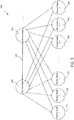
- FIG. 4 illustrates a communications grid 400 including three control nodes and one or more worker nodes, according to embodiments of the present technology.
- Communications grid 400 includes control node 402, control node 404 and control node 406.
- Control node 402 and control node 404 are communicatively connected via communication path 451. Therefore, control node 402 and control node 404 may transmit information, communications path 451, including information related to the communications grid or notifications, to and receive information from each other.
- Control node 402 and control node 406 are communicatively connected via communication path 453. Therefore, control node 402 and control node 406 may transmit information, via communication path 453, including information related to the communications grid or notifications, to and receive information from each other.
- Control node 404 and control node 406 are communicatively connected via communication path 455. Therefore, control node 404 and control node 406 may transmit information, via, communications path 455, including information related to the communications grid or notifications, to and receive information from each other.
- communications grid 600 is shown in FIG. 6 as including three control nodes, the communications grid may include more than three control nodes or less than two control nodes (as shown, for example, in FIGS. 5 and 6 ).
- Communications grid 400 also includes one or more worker nodes. Shown in FIG. 4 are six worker nodes: worker node 410 (or worker node 1), worker node 412 (or worker node 2), worker node 414 (or worker node 3), worker node 416 (or worker node n-2), worker node 418 (or worker node n-1), and worker node 420 (or worker node n).
- FIG. 4 shows six worker nodes
- a communications grid may include more or less than six worker nodes.
- a communications grid may include one, two, or any other number of worker nodes.
- the number of worker nodes included in a communications grid may be dependent upon how large the project or data set is being implemented by the communications grid.
- the number of worker nodes included in a communications grid may also be dependent upon other factors, such as the capacity of each worker node, the time designated for the communications grid to complete the project, among others.
- a control node such as control node 402 may be designated as the primary control node in communications grid 400.
- Primary control node 402 may be configured to have a similar role (and perform the same or similar functions) in communications grid 400 as primary control node 602 in communications grid 600 as described with respect to FIG. 6 (and as control node 502 in FIG. 5 ).
- the other two control nodes in communications grid 400 such as control nodes 404 and 406, may be designated as backup control nodes. Control nodes 404 and 406 may be referred to herein as backup control nodes.
- control nodes 404 and 406 may be primary control nodes in other embodiments In such an embodiment where control nodes 404 and 406 are backup control nodes, each of the backup control nodes 404 and 406 may perform similar functions, either individually or in combination, to backup control node 304 in communications grid 300.
- backup control nodes 404 and 406 may each receive information regarding the communications grid 400, including periodic snapshots or other information about the communications grid, from the primary control node 402.
- Either backup control node 404 or backup control node 406 may, similar to backup control node 304 in communications grid 300, take over or substitute for primary control node 402 if primary control node 402 were to fail.
- the backup control node that takes over for a failed primary control node 402 may do so such that it may perform similar functions to backup control node 304 in communications grid 300 after a failure of primary control node 302, and thus may continue the functions or projects being performed by failed primary control node 402.
- the backup control node may control the worker nodes that were connected to primary control node 402 before primary control node 402 failed (and which, as noted, may also be connected to control nodes 404 and 406) and control the project or projects being performed by those worker nodes.
- Different methods may be performed to determine which backup control node of a set of backup control nodes (e.g., backup control nodes 404 and 406) will take over for failed primary control node 402 and become the new primary control node.
- the new primary control node may be chosen based on the unique identifiers assigned to each backup control node (e.g., whichever backup control node has the higher or lower unique identifier). Such a ranking of unique identifiers may be called a "hierarchy" of the backup control nodes.
- a backup control node may be assigned to be the new primary control node by another device in the communications grid (e.g., the failed primary control node 402) or from an external device (e.g., a system infrastructure or an end user, such as a server or computer, controlling the communications grid).
- the backup control node that takes over as the new primary control node may be designated based on bandwidth or other statistics about the communications grid. For example, the decision may be based on which node has more bandwidth, which node includes a more recent version of a snapshot of the communications grid, which node is better equipped (e.g., using statistics about the node or the rest of the communications grid) to handle the current project being executed by the communications grid, among others.
- backup control nodes may communicate with each other (e.g., via communication paths 451, 453 and 455), an internal algorithm may be executed, or information may be shared between the backup control nodes, to designate one of the backup control nodes as the new primary control node.
- FIG. 5 illustrates a communications grid 500 including two control nodes and one or more worker nodes, according to embodiments of the present technology.
- Communications grid 500 includes primary control node 502 and backup control node 504.
- Primary control node 502 and backup control node 504 may have similar roles in communications grid 500 as control nodes 602 and 604, respectively, in communications grid 600 in FIG. 6 .
- Primary control node 502 and backup control node 504 are communicatively connected via communication path 551. Therefore, primary control node 502 and backup control node 504 may transmit information, including information related to the communications grid or notifications, to and receive information from each other.
- communications grid 500 is shown in FIG. 5 as including two control nodes, the communications grid may include more than two control nodes (for example, as shown in FIG. 4 ) or less than two control nodes (as shown, for example, in FIG. 5 ).
- Communications grid 500 also includes one or more worker nodes. Shown in FIG. 5 are four worker nodes: worker node 510 (or worker node 1), worker node 512 (or worker node 2), worker node 514 (or worker node 3), and worker node 516 (or worker node 4. Although FIG. 5 shows four worker nodes, a communications grid according to embodiments of the present technology may include more or less than four worker nodes.
- a primary control node may transmit snapshots of the communications grid so that a backup control node (e.g., backup control node 504) always has a recent snapshot of the communications grid.
- primary control node 502 may transmit communications grid snapshot 540 to backup control node 504.
- the snapshot may include the structure of the grid including the worker nodes in the grid and their relationships with the primary control node, the status of a project (including, for example, the status of each worker node's portion of the project), among other information.
- the snapshot may also include analysis or results received from worker nodes in the communications grid for either partial of whole portions of the project.
- the snapshot may also include any other information that assists the backup control node to continue processing the job from a known state of the job after a primary control node failure.
- the backup control node 504 may receive and store snapshot 540 received from the primary control node 502.
- the backup control node 504 may initiate a receipt of a snapshot of the communications grid by requesting such a snapshot (or other information) from the primary control node, or the primary control node may send such information periodically to the backup control node.
- Backup control node 504 may store snapshot 540 in storage, such as in local storage 525.
- Local storage 525 may be a short term storage, such as cache, or a more long term storage within backup control node 504.
- backup control node 504 may store snapshot 540 (or other data) in a remote location. For example, backup control node 504 may, after receiving communications grid snapshot 540 from primary control node 502, transmit snapshot 540 to a storage external to backup control node 504. Backup control node 504 may then, upon receiving or detecting a notification of a failure of a primary control node, retrieve a stored grid snapshot, such as snapshot 540, from storage.
- FIG. 6 illustrates a communications grid 600 including two control nodes, including a backup control node with a stored grid snapshot, and one or more worker nodes, according to embodiments of the present technology. More specifically, FIG. 6 illustrates that primary control node 602 may fail (indicated by dotted lines), and therefore that communication paths between the primary control node 602 and other nodes on the communications grid (e.g., path 651 between primary control node 602 and backup control node 604 as well as those paths between primary control node 602 and worker nodes 610-616) may be severed because of such a failure.
- communication paths between the primary control node 602 and other nodes on the communications grid e.g., path 651 between primary control node 602 and backup control node 604 as well as those paths between primary control node 602 and worker nodes 610-616) may be severed because of such a failure.
- backup control node 604 may be communicatively connected (e.g., wired or wirelessly) to each of the worker nodes within communications grid 600.
- the backup data may allow the backup control node to take over as primary control node if the primary control node fails. More specifically, the backup data may allow the backup control node to continue the project being implemented and controlled by the primary control node after a failure of the primary control node without having to start the project over from scratch. If the primary control node fails, the backup control node 504 may retrieve the most recent version (or another stored version, if applicable) of the snapshot received from the primary control node 502 and use the snapshot (and other backup data) to continue the project from the stage of the project indicated by the backup data.
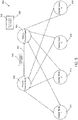
- FIG. 7 illustrates a communications grid 700 including two control nodes, including a backup control node with a stored grid snapshot and one or more worker nodes, according to embodiments of the present technology.
- Communications grid 700 is similar to communications grid 600, but further illustrates that backup control node 704 may receive notification of a failure of the primary control node 702 from several different sources.
- a backup control node e.g., backup control node 704
- Backup control node 704 may be notified that primary control node 702 has failed in a variety of different ways.
- backup control node 704 may receive a communication including a notification, such as communication 745, including an indication that primary control node 702 has failed or will fail within a certain amount of time.
- Backup control node 704 may receive such a notification from primary control node 702 itself.
- Primary control node 702 may identify that it has or will fail and subsequently or simultaneously transmit a notification of this issue to backup control node 704, to another node or group of nodes on the grid, or to a server or administrator (e.g., server/administrator 760) or another system infrastructure internal or external to the communications grid.
- Backup control node may then receive a communication 745 from the server or administrator 760.
- such a notification may come after the server or administrator 760 has received such a notification from the primary control node 702.
- the server or administrator 760 may have received such a notification from a worker node within the grid, or from another source.
- the server or administrator 760 may transmit periodic heartbeat messages to the primary control node 702 to determine whether primary control node 702 is working (i.e. has not failed), and may have initiated a notification transmitted to backup control node 704 because it determined that primary control node 702 failed since it did not receive a response to one or more of its heartbeat messages for a certain predetermined period of time.
- Backup control node 704 may then receive a notification of a primary control node failure directly from a worker node, such as from worker node 716 as shown in FIG. 7 .
- FIG. 8 illustrates a communications grid 800 including a new primary control node and former backup control node, and one or more worker nodes, according to embodiments of the present technology.
- Communications grid 800 includes new primary control node 804, which may have transitioned from being a former backup control node before a previous primary control node failed.
- new primary control node 804 is, as it was when it was a backup control node, connected to one or more worker nodes.
- new primary control node 804 is connected to worker nodes 810, 812, 814, and 816.
- new primary control node 804 may be connected to a fewer or greater number of worker nodes than the four worker nodes shown in FIG. 8 .
- New primary control node 804 may substitute or take over for a previous primary control node in the same capacity or functionality as the former, now failed, primary control node.
- new primary control node 804 may control the project being run on the communications grid 800, and therefore may control the worker nodes connected to it and executing different portions of the project.
- New primary control node 804 upon becoming the primary control node within communications grid 800, may begin the project anew (for example, if the last known state of the grid as stored by the new primary control node is the beginning of the project). In another embodiment, new primary control node 804 may roll back to a checkpoint by resuming work on the project at a checkpoint at some point during the progress of the project being executed. In an embodiment, new primary control node 804 may resume execution of the project, along with the worker nodes connected to it, from the exact point where the former primary control node left off.
- new primary control node 804 may resume execution of the project from a checkpoint (i.e., rolling back to a checkpoint) that is at a point in the project previous to the point where the previous primary control node left off.
- the new primary control node 804 may obtain information about this checkpoint using a snapshot of the grid retrieved from storage within new primary control node 804 or from storage within another node or another device.
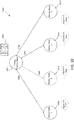
- FIG. 9 illustrates a communications grid 900 including a primary control node and one or more worker nodes, according to embodiments of the present technology.
- Communications grid 900 includes new primary control node 902 and worker nodes 910, 912, 914 and 916.
- primary control node 902 may distribute the work within a project being executed to each of the worker nodes within the communications grid such that each worker node performs or executed a portion of the project.
- worker nodes 910, 912, 914 and 916 may each be assigned a one-quarter portion of the project being executed by the communications grid 900 and being controlled by primary control node 902.
- primary control node 902 may transmit instructions to the worker nodes, for example via communications paths 960, 962, 964 and 966, respectively.
- the worker nodes may also transmit information primary control node 902.
- the worker nodes may generate (and, for example, locally store) and transmit checkpoints of their progress within a project, or their assigned portion of a project, to primary control node 902 so that primary control node 902 receives and stores periodic checkpoints or statuses of the progress of each of the worker nodes.
- the received checkpoints for each worker node may allow primary control node 902 to compile statuses of the progress of the project being executed on the communications grid.
- the checkpoints may allow primary control node 902 to generate a snapshot of the communications grid, or the checkpoints may be treated as separate, independent data to be used in other capacities by the primary control node. After the checkpoints are received, they may be stored by the primary control node in storage 925. The primary control node 902 may also store any data generated from the checkpoints, including for example a snapshot of the communications grid.
- Checkpoints may be generated by a worker node (or a control node) after a stage of the project has been completed (e.g., if the project is a multi-stage operation). Alternatively, checkpoints may be generated after a certain amount or amounts of the project (e.g., a certain percentage) have been completed (e.g., if the project includes a large data set). The method of generating and saving or transmitting checkpoint information may be chosen based on the project and/or situation by the primary control node (or, in other embodiments, by other nodes on the grid or by a user external to the grid).
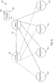
- FIGS. 10-12 illustrate a communications grid including a control node and one or more worker nodes, according to embodiments of the present technology.
- Communications grid 1000 includes primary control node 1002 and worker nodes 1010, 1012, 1014 and 1016.
- primary control node 1002 may distribute the work within a project or data set being executed to each of the worker nodes within the communications grid such that each worker node performs or executed a portion of the project.
- worker nodes 1010, 1012, 1014 and 1016 may each be assigned a one-quarter portion of the project being executed by the communications grid 1000 and being controlled by primary control node 1002.
- the worker nodes may transmit checkpoints of their progress within a project, or their assigned portion of a project, to primary control node 1002 so that primary control node 1002 receives and stores periodic checkpoints or statuses of the progress of each of the worker nodes.
- Communications grid 1000 also shows that one of the worker nodes, worker node 1012 may fail (indicated by dotted lines in FIG. 10 ), and therefore that communication paths between the worker node 1012 and other nodes on the communications grid (e.g., path 1062 between primary control node 1002 and worker node 1012) may be severed because of such a failure.
- communications grid 1000 may account for a failure of a worker node, such as worker node 1012.
- worker node 1012 is communicatively connected to primary control node 1002, which may control worker node 1012 and/or the work being performed by worker node 1012. If worker node 1012 fails, then primary control node 1002 may detect that worker node 1012 has failed or may receive a notification that worker node 1012 has failed.
- primary control node 1002 may be notified that worker node 1012 has failed by another worker node (e.g., worker node 1010, 1014 and/or 1016, which are also communicatively connected to primary control node 1002) or, if one exists, another control node (e.g., a backup control node) on communications grid 1000.
- primary control node 1002 may be notified by a user (e.g., server or administrator 1170 in FIG. 11 of the grid via communication 1172, as shown within communications grid 1100 in FIG. 11 , discussed further herein).
- Alternative embodiments include using thresholds to determine when, after a predetermined amount of time, it should be established or assumed that a worker node has failed.
- a worker node may not transmitted an acknowledgement communication (e.g., ACK) or another expected communication, as noticed by a control node or other node expected to receive such a communication, for a certain amount of time that is greater than a predetermined threshold, it may be assumed that the worker node has failed. Such a determination may allow a control node to redistribute work being performed by a failed worker node to another worker node.
- ACK acknowledgement communication
- primary control node 1002 may redistribute the work being performed by worker node 1012 to other worker nodes on communications grid 1000. For example, after primary control node 1002 is knows that worker node 1012 has failed, primary control node 1002 may transmit a communication (e.g., message or notification) to each of the other worker nodes (e.g., all or part of the worker nodes still connected to primary control node 1002 and on communications grid 1000) including the portion of the work being redistributed from worker node 1012 that they are assigned to work on. For example, as shown in communications grid 1200 of FIG.
- a communication e.g., message or notification
- primary control node 1002 may transmit a communication 1274 to worker node 1010, a communication 1576 to worker node 1014, and a communication 1278 to worker node 1016 including such information.
- worker nodes 1010, 1014, and 1016 may add the work identified in their received communication to the work that it will perform on the project. For example, if the remaining work from failed worker node 1012 is redistributed equally between worker node 1010, 1014, and 1016, each of worker nodes 1010, 1014, and 1016 may be assigned one-third of the total work remaining for the project after such work has been reassigned.
- an alternative may include adding a new worker node to the grid to take on the additional work.
- primary control node 1002 may transmit a communication (e.g., break communicator message) to each of the worker nodes still on communications grid 1000 including a message that each of the worker nodes should purposefully fail also.
- the message may include or cause a communication error within each worker node so that each of the worker nodes still on the grid fail.
- each worker nodes After each of the worker nodes fails, they may each retrieve their most recent saved checkpoint of their status.
- Each worker node may also retrieve the status or checkpoint of the first failed worker node, worker node 1012. For example, as shown in FIG. 12 , primary control node 1002 may transmit the checkpoint 1242 of failed worker node 1012 to worker nodes 1010, 1014 and 1016.
- each of the still existing (e.g., non-failed) worker nodes may continue work on the project from their most recent checkpoint at the same time and so they do not miss any of the work to be performed on the project.
- This may also allow the worker nodes to continue work on the work redistributed from the failed worker node at the point where worker node 1012 failed when performing the work.
- Using such a checkpoint may allow the worker nodes to be efficient so as to not duplicate work already completed or to not miss work that needs to be completed.
- Such checkpoints may be stored within each worker node or may be retrieved from another device or source (e.g., another worker node, a control node, a cloud network, or other location).
- a worker node or other devices or networks that has stored the checkpoint may transmit the checkpoint or other status information to the new control node.
- FIG. 13 is a flow chart 1300 showing an example process for adjusting a work project in a communications grid after a failure of a control node, according to embodiments of the present technology.
- the process may include, for example, receiving, at a backup control node connected to a primary control node and a worker node on a communications grid, grid status information, the grid status information including a project status of the primary control node or a project status of the worker node, wherein the project status of the primary control node and the project status of the worker node include a status of one or more portions of a project being executed by the primary and worker nodes in the communications grid (step 1302).
- the process may also include storing the grid status information within the backup control node (step 1304).
- the process may also include receiving a failure communication including an indication that the primary control node has failed (step 1306).
- the process may also include designating the backup control node as a new primary control node based on the failure communication upon receiving the failure communication (step 1308).
- the process may also include receiving updated grid status information based on the indication that the primary control node has failed, wherein the updated grid status information includes an updated project status of the primary control node or an updated project status of the worker node (step 1310).
- the process may also include transmitting a set of instructions based on the updated grid status information, wherein the set of instructions includes instructions for the worker nodes to continue work on the project after failure of the primary control node (step 1312).
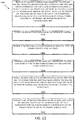
- FIG. 14 is a flow chart 1400 showing an example process for adjusting a work project in a communications grid after a failure of a worker node, according to embodiments of the present technology.
- the process may include, for example, transmitting, at a primary control node connected to one or more worker nodes on a communications grid, worker instructions related to a project being executed by the one or more worker nodes (step 1402).
- the process may also include generating a snapshot of the communications grid, wherein the snapshot of the communications grid includes a project status of each of the one or more worker nodes, wherein a project status of a worker node includes a project checkpoint of a portion of the project being executed by the worker node in the communications grid (step 1404).
- the process may also include determining that a failed worker node of the one or more worker nodes has failed at a failure time (step 1406).
- the process may also include determining a project status of the failed worker node using the snapshot of the communications grid, wherein the project status of the failed worker node includes a project checkpoint of the failed worker node at the failure time of the failed worker node (step 1408).
- the process may also include transmitting updated worker instructions, wherein the updated worker instructions include the project status of the failed worker node and updated instructions related to the project being executed by the one or more worker nodes, wherein when the updated worker instructions are received, a functioning worker node completes the portion of the project being executed by the failed worker node (step 1410).
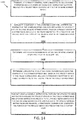
- FIG. 15 is a flow chart 1500 showing an example process for adjusting a work project in a communications grid after a failure of a control node, according to embodiments of the present technology.
- the process may include, for example, receiving, by a backup control node in a communications grid, an initial communication including an indication that a primary control node is connected to the communications grid (step 1502).
- the process may also include receiving a snapshot of the communications grid, wherein the snapshot of the communications grid includes a worker status of each of a plurality of worker nodes connected to the primary control node and the backup control node (step 1504).
- the process may also include determining a time period since the initial communication was received (step 1506).
- the process may also include comparing the time period with a threshold time period to determine that the primary control node has failed, wherein upon receiving the failure communication, the backup control node is a new primary control node (step 1508).
- the process may also include transmitting a set of instructions based on the worker status of one or more worker nodes of the plurality of worker nodes, wherein the set of instructions includes instructions for continuing work on the project after failure of the primary control node (step 1510).
- FIG. 16 is a flow chart 1600 showing an example process for authenticating a connection between nodes from the perspective of a grid server (e.g., from an established node on a grid), according to embodiments of the present technology.
- a control node e.g., primary control node
- receives a connection from another control node it may first check to see if the peer node is in a stored list of configured nodes in the grid. If it is not on the list, it may clear (i.e. refuse) the connection. If it is on the list, it may then attempt to authenticate the connection so as to make sure that the new node belongs on the grid.
- Authentication may be shown through the exchange of different types of messages that allow for either one-way or two-way authentication.
- the different types of messages may include:
- an authenticating node may wait for a message (block 1602) and receive a message (block 1604).
- the node may determine if the message is either an ATR or ATNR message (block 1606). If the message is neither an ATR or ATNR message, then the node may transmit an ATF message and process may end. If the message is determined to be an ATR or ATNR message, then the authenticating node may, at 1610 and 1612, validate the data received. If the data is valid, and the message was an ATR (as determined at block 1614), then the node may generate a response to the ATR at block 1616 because the ATR message requires a response.
- the node may determine if more authentication data is needed at block 1618, and sends an ATR at 1630 if so. If not, then the node may transmit an ATNR at 1620 and wait for a response at 1622. At 1624, the node may determine if the received response (at block 1622) is an ATC. If so, the authentication was successful as shown in block 1640. If not, it may send an ATF in response at block 1632 (because authentication failed, as shown in blocks 1634 and 1638).
- FIG. 17 is a flow chart 1700 showing an example process for authenticating a connection between nodes from the perspective of a grid client (e.g., from a new node on a grid), according to embodiments of the present technology.
- the flow chart 1700 shown in FIG. 17 is very similar to flow chart 1600 shown in FIG. 16 , except flow chart 1700 includes blocks 1702, 1704, 1706 and 1708 to determine if authentication data will be needed in response.
- the node may generate initial authentication data and then, at block 1704, determine if authentication data is needed in response. If so, it may transmit an ATR at 1706 to require authentication data in response. If not, it may transmit an ATNR at 1728.
- an authenticating node may wait for a message (block 1712) and receive a message.
- the node may determine if the message is either an ATR or ATNR message (block 1714). If the message is neither an ATR or ATNR message, then the node may transmit an ATF message (block 1736) and process may end because the process failed (as shown in nodes 1738 and 1740). If the message is determined to be an ATR or ATNR message, then the authenticating node may, at 1718 and 1720, validate the data received.
- the node may generate a response to the ATR at block 1724 because the ATR message requires a response. Then, the node may determine if more authentication data is needed at block 1726, and sends an ATR at 1715 if so. If not, then the node may transmit an ATNR at 1728 and wait for a response at 1730. At 1732, the node may determine if the received response is an ATC. If so, the authentication was successful as shown in block 1742. If not, it may send an ATF in response at block 1636. Referring back to node 1722, if the message is determined to not be an ATR, then an ATC message may be sent (at node 1740) because the authentication was successful (as shown in FIG. 1742).
- FIG. 18 is a flow chart 1800 showing an example process to assign a list of nodes (numbered m through n) as children to a node, such as a control node, according to embodiments of the present technology.
- node m may be assigned a as a left child (e.g., worker) node.
- n - m 1, or in other words whether the last child assigned (m) is less than or equal to the total number of children (n). If so, the process may end. If not, node m + 1 may be assigned as a right child at block 1806.
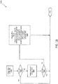
- FIG. 19 is a flow chart 1900 showing an example process for a primary control node to distribute work for a client project between the other nodes in a communications grid, according to embodiments of the present technology.
- the primary control node determines how to distribute the work to the worker nodes (and if such distribution is possible). For example, this step may take place after worker nodes have been assigned and authenticated on the grid, as described in FIGS. 16-18 .
- the primary control node may then determine, at block 1904, if the grid includes enough worker nodes to complete the stage of the work. If not, the operation or stage may be determined to have failed at block 1906. If so, the primary control node may save the state at block 1908 and transmit grid snapshot or state information to the backup control nodes at block 1910.
- the primary control node may then distribute work (from a certain stage of the work, if the work is in stages) across the worker nodes at block 1912, and wait for the worker nodes to complete the stage or fail at block 1914. It may then be determined if any workers failed at block 1916. If one or more workers failed, then one of several processes may take place to remedy the failure. For example, the primary control node may redistribute work among the rest of the worker nodes. In another example, the primary control node may induce failure of all worker nodes (e.g., at block 1918) so that each worker node may restart their work at a recent snapshot of the grid's work on the project.
- the worker nodes may then restore their work on the state to a saved state (e.g., using a saved snapshot) at block 1920, and then retry the work on the stage (on which the failed worker node failed) at block 1922.
- the primary control node may consider at block 1924 whether the stage was the final stage of the project. If so, the primary control node may report a successful completion at block 1928. If not, then the primary control node may assign work to the worker nodes for the next stage in the project at block 1926.
- FIG. 20 is a flow chart 2000 showing an example process for a backup control node to receive and store updated status information in a communications grid, according to embodiments of the present technology.
- a communications grid may have one, two, three, or more control nodes.
- FIG. 20 may only apply to a communications grid that includes more than one control node.
- the backup control node may wait for a status update to be transmitted by the primary control node.
- the status or grid snapshot may be updated.
- the status may terminate in blocks 2008, 2010 and 2012.
- the process may terminate at block 1212. If not, then the backup control node may log an error message at block 2010 and then terminate at block 2012. Referring back to block 2014, if the status does not include an updated state, then the backup control node may determine that the primary control node has failed at block 2016. At block 2026, the latest stored state may be restored (e.g., from the primary control node) at block 2026, and the backup control node may take over as primary control node at blocks 2028 and 2018.
- FIG. 21 is a flow chart 2100 showing an example process for a worker node during a communications grid computation, according to embodiments of the present technology.
- a worker node may accept work as assigned from a control node, and may perform the assigned work until it has completed the work or until the worker node has failed (at block 2106), as determined at block 2108. If the worker node failed, then it may restore its last saved state (e.g., using a previously stored state or snapshot) at block 2114 and accept a next work item from the control node (e.g., back to block 2104). If the worker node didn't fail, and no error was found, then the worker node may determine if the completed state was the final stage of the project at block 2110.
- the worker node may report a success at block 2128 and terminate the process. If it was not the final stage, then the worker node may move to the next stage in its assigned work at block 2112. Before any stage is begun by a worker node, it may save its current state (e.g., at block 2104) so that the worker node will have its previous (and recent) state stored in case the worker node fails. The worker node may transmit its state at any time that it is requested to do so by, for example, a control node and the state may be incorporated as part of a grid snapshot.
- FIG. 22 is a flow chart 2200 showing an example process for broadcasting data within a communications grid, according to embodiments of the present technology.
- a node may determine if the data that it would like to broadcast to the rest of the nodes in the grid is large (e.g., greater than 64 KB). If the data is determined to not be large, then the node may determine if the data is running on worker nodes (e.g., not running on a control node) in block 2204. If no, then the node may, at block 2208, wait for all worker nodes to be ready to received data and, at block 2210, transmit the data to each worker node that it would like to run the data. If yes, then the node may transmit data to the worker nodes at block 2210.
- worker nodes e.g., not running on a control node
- the node may determine if the data is running on worker nodes in block 2214. If not, then the node may organize the other nodes into a tree (e.g., using the algorithm shown in FIG. 21 ) at block 2216. Then, the node may wait for all workers to be ready to receive data at block 2220 (similar to block 2208), and then send the data to its immediate worker children nodes at block 2216. Referring back to block 2214, if it is determined that the data is running on worker nodes, then the node may inform the control node that the worker nodes are yet ready to receive the data (at block 2218).
- the node may wait for a block of data from its immediate parent (e.g., a control node) at block 2222, copy data to an output buffer at block 2224, and resend data to any of its immediate worker children nodes at block 2226. Then, it may be determined if all data has been received by the worker nodes at block 2228. If so, then the process may end. If not, then it may revert back to block 2222 and wait, again, for a block of data from its immediate parent node.
- its immediate parent e.g., a control node
- FIG. 23 is a flow chart 2300 showing an example process for a reduction algorithm within a communications grid, according to embodiments of the present technology.
- flow chart 2300 shows a process for obtaining input data from several or every node in a communications grid, and performing an operation to obtain a single result block based on that data.
- embodiments of the present technology restrict reduction operations so that it is required that the block of data be the same size on every node, and that the operation not depend on the order of operations.
- a reduction operation can be performed on a single object on each node, or on a list of objects on each node.
- Common reduction operations may include: multiply (e.g., find the product of all of the values on all of the nodes), sum (e.g., find the sum of all of the values on all of the nodes), minimum (e.g., find the smallest value on all of the nodes), and maximum (e.g., find the largest value on all of the nodes), among others.
- Flow chart 2300 may begin with a determination of whether the reduction is large (block 2302). If so, the grid may organize the nodes into a tree (block 2304), break input buffer into blocks (block 2306), and copy the next block into the reduction buffer (block 2308).
- a node may include three buffers: (1) an input buffer, which may contain data originating from the local machine; (2) an output buffer, present on the control node; and (3) a "reduction buffer,” which may be a temporary buffer on each node that can be used to compute a partial result for itself and all child nodes connected to it.
- the output buffer may be the same size as the input buffer (although larger than the reduction buffer), and the output buffer may represent the result of the reduction operation across all nodes in the grid.
- the input buffer may be subdivided into blocks, so that each block is small enough to fit into the reduction buffer.
- the reduction buffer may be large enough to contain 5,000 double precision numbers.
- the input buffer may be split up into 200 blocks of 5,000 double precision numbers each.
- a single block of data may be copied out of the input buffer and into the reduction buffer.
- the grid may then determine whether the block has any direct children (block 2326). If no, then the grid may check to see if the block has a parent node (block 2332). If yes, the grid may then send a "ready to receive" signal to the direct children (block 2328), wait for data blocks to be sent from the children (block 2316), and merge the child data blocks into the buffer (block 2317), for example the reduction buffer. Then, the grid may check to see if the block has a parent node (block 2332). If no, then the grid may copy the reduction buffer to the output buffer (block 2330).
- the reduction buffer may contain the result for a subset of the data, that result may then be copied into the correct portion of the output buffer. If any more blocks of data from the input buffer still need to be processed (step 2338), execution may continue with step 2308. Referring back to block 2332, if the block does have a parent node, then the grid may then wait for a "ready to receive" signal from the parent (block 2328) and send a reduction buffer to the parent (block 2336).
- the reduction buffer may contain the result of the reduction operation for a single block of data for the subtree of the grid rooted at the current node.
- the contents of the current node's reduction buffer may be forwarded to its parent node, so that its parent node can continue the operation.
- the grid may then check to see if all blocks have been processed at block 2338. If not, then the flow chart reverts back to block 2308 to copy the next block into the reduction buffer. If so, then the process moves to block 2338 to determine if all blocks have been processed.
- the grid may determine if it is running on a control node at block 2310. If not, the grid may wait for a "ready to receive" signal from the control node (block 2314), send all data to the control node (block 2316), and end the process. If so, then the grid may copy local data into an output buffer (block 2312), and send a "ready to receive” signal to all worker nodes (block 2318), receive data from a worker node as available (block 2320), and merge the data into an output buffer (block 2322). At block 2324, the grid determines if all data has been received. If not, then the process reverts back to block 2318. If so, then the process ends.
- An example set of operations available at a communicator handle of a node are described as follows.
- the systems and methods may include data transmissions conveyed via networks (e.g., local area network, wide area network, Internet, or combinations thereof, etc.), fiber optic medium, carrier waves, wireless networks, etc. for communication with one or more data processing devices.
- the data transmissions can carry any or all of the data disclosed herein that is provided to or from a device.
- Some aspects may utilize the Internet of Things (IoT), where things (e.g., machines, devices, phones, sensors) can be connected to networks and the data from these things can be collected and processed within the things and/or external to the things.
- IoT Internet of Things
- things e.g., machines, devices, phones, sensors
- high value analytics can be applied to identify hidden relationships and drive increased efficiencies.
- This can apply to both Big Data analytics and realtime (streaming) analytics.
- the methods and systems described herein may be implemented on many different types of processing devices by program code comprising program instructions that are executable by the device processing subsystem.
- the software program instructions may include source code, object code, machine code, or any other stored data that is operable to cause a processing system to perform the methods and operations described herein.
- Other implementations may also be used, however, such as firmware or even appropriately designed hardware configured to carry out the methods and systems described herein.
- the systems' and methods' data may be stored and implemented in one or more different types of computer-implemented data stores, such as different types of storage devices and programming constructs (e.g., RAM, ROM, Flash memory, removable memory, flat files, temporary memory, databases, programming data structures, programming variables, IF-THEN (or similar type) statement constructs, etc.).
- storage devices and programming constructs e.g., RAM, ROM, Flash memory, removable memory, flat files, temporary memory, databases, programming data structures, programming variables, IF-THEN (or similar type) statement constructs, etc.
- data structures may describe formats for use in organizing and storing data in databases, programs, memory, or other computer-readable media for use by a computer program.
- a computer program (also known as a program, software, software application, script, or code) can be written in any form of programming language, including compiled or interpreted languages, and it can be deployed in any form, including as a stand-alone program or as a module, component, subroutine, or other unit suitable for use in a computing environment.
- a computer program does not necessarily correspond to a file in a file system.
- a program can be stored in a portion of a file that holds other programs or data (e.g., one or more scripts stored in a markup language document), in a single file dedicated to the program in question, or in multiple coordinated files (e.g., files that store one or more modules, sub programs, or portions of code).
- a computer program can be deployed to be executed on one computer or on multiple computers that are located at one site or distributed across multiple sites and interconnected by a communication network.
- the processes and logic flows and figures described and shown in this specification can be performed by one or more programmable processors executing one or more computer programs to perform functions by operating on input data and generating output.
- a computer can also include, or be operatively coupled to receive data from or transfer data to, or both, one or more mass storage devices for storing data, e.g., magnetic, magneto optical disks, or optical disks.
- mass storage devices for storing data
- a computer need not have such devices.
- a computer can be embedded in another device, e.g., a mobile telephone, a personal digital assistant (PDA), a tablet, a mobile viewing device, a mobile audio player, a Global Positioning System (GPS) receiver, to name just a few.
- PDA personal digital assistant
- GPS Global Positioning System
- Computer readable media suitable for storing computer program instructions and data include all forms of nonvolatile memory, media and memory devices, including by way of semiconductor memory devices, e.g., EPROM, EEPROM, and flash memory devices; magnetic disks, e.g., internal hard disks or removable disks; magneto optical disks; and CD ROM and DVD-ROM disks.
- semiconductor memory devices e.g., EPROM, EEPROM, and flash memory devices
- magnetic disks e.g., internal hard disks or removable disks
- magneto optical disks e.g., CD ROM and DVD-ROM disks.
- the processor and the memory can be supplemented by, or incorporated in, special purpose logic circuitry.
- a module or processor includes but is not limited to a unit of code that performs a software operation, and can be implemented for example as a subroutine unit of code, or as a software function unit of code, or as an object (as in an object-oriented paradigm), or as an applet, or in a computer script language, or as another type of computer code.
- the software components or functionality may be located on a single computer or distributed across multiple computers depending upon the situation at hand.
- the computer may include a programmable machine that performs high-speed processing of numbers, as well as of text, graphics, symbols, and sound.
- the computer can process, generate, or transform data.
- the computer includes a central processing unit that interprets and executes instructions; input devices, such as a keyboard, keypad, or a mouse, through which data and commands enter the computer; memory that enables the computer to store programs and data; and output devices, such as printers and display screens, that show the results after the computer has processed, generated, or transformed data.
- Implementations of the subject matter and the functional operations described in this specification can be implemented in digital electronic circuitry, or in computer software, firmware, or hardware, including the structures disclosed in this specification and their structural equivalents, or in combinations of one or more of them. Implementations of the subject matter described in this specification can be implemented as one or more computer program products, i.e., one or more modules of computer program instructions encoded on a computer readable medium for execution by, or to control the operation of, data processing apparatus.
- the computer readable medium can be a machine-readable storage device, a machine-readable storage substrate, a memory device, a composition of matter effecting a machine-readable propagated, processed communication, or a combination of one or more of them.
- data processing apparatus encompasses all apparatus, devices, and machines for processing data, including by way of example a programmable processor, a computer, or multiple processors or computers.
- the apparatus can include, in addition to hardware, code that creates an execution environment for the computer program in question, e.g., code that constitutes processor firmware, a protocol stack, a graphical system, a database management system, an operating system, or a combination of one or more of them.
- Some systems may use Hadoop®, an open-source framework for storing and analyzing big data in a distributed computing environment.
- Some systems may use cloud computing, which can enable ubiquitous, convenient, on-demand network access to a shared pool of configurable computing resources (e.g., networks, servers, storage, applications and services) that can be rapidly provisioned and released with minimal management effort or service provider interaction.
- Some grid systems may be implemented as a multi-node Hadoop® cluster, as understood by a person of skill in the art.
- ApacheTM Hadoop® is an open-source software framework for distributed computing.
- Some systems may use the SAS® LASRTM Analytic Server in order to deliver statistical modeling and machine learning capabilities in a highly interactive programming environment, which may enable multiple users to concurrently manage data, transform variables, perform exploratory analysis, build and compare models and score.
- Some systems may use SAS In-Memory Statistics for Hadoop® to read big data once and analyze it several times by persisting it in-memory for the entire session.
- Some systems may use a combination of several other types of systems or servers, including those systems and servers mentioned herein.
- configurations may be described as a process that is depicted as a flow diagram or block diagram. Although each may describe the operations as a sequential process, many of the operations can be performed in parallel or concurrently. In addition, the order of the operations may be rearranged. A process may have additional steps not included in the figure.
- examples of the methods may be implemented by hardware, software, firmware, middleware, microcode, hardware description languages, or any combination thereof. When implemented in software, firmware, middleware, or microcode, the program code or code segments to perform the necessary tasks may be stored in a non-transitory computer-readable medium such as a storage medium. Processors may perform the described tasks.
Landscapes
- Engineering & Computer Science (AREA)
- Theoretical Computer Science (AREA)
- Quality & Reliability (AREA)
- Physics & Mathematics (AREA)
- General Engineering & Computer Science (AREA)
- General Physics & Mathematics (AREA)
- Testing And Monitoring For Control Systems (AREA)
- Hardware Redundancy (AREA)
- Telephonic Communication Services (AREA)
- Retry When Errors Occur (AREA)
- Management, Administration, Business Operations System, And Electronic Commerce (AREA)
Claims (15)
- Procédé mis en oeuvre par ordinateur, comprenant :la transmission, depuis un noeud de commande principal (902, 1002) connecté à un ou plusieurs noeuds de travail (910, 912, 914, 916, 1010, 1012, 1014, 1016) sur une grille de communications (900, 1000), d'instructions de travail relatives à un projet en cours d'exécution par le ou les noeuds de travail ;la génération, par le noeud de commande principal, d'un instantané de la grille de communications, l'instantané de la grille de communications comportant un état de projet de chacun du ou des noeuds de travail, un état de projet d'un noeud de travail comportant un état d'une partie du projet en cours d'exécution par le noeud de travail dans la grille de communications, et l'instantané comportant un point de contrôle de projet qui indique un point au cours de l'exécution d'une partie du projet ;la détermination, par le noeud de commande principal, qu'un noeud de travail défaillant parmi le ou les noeuds de travail a subi une défaillance, le noeud de travail défaillant ayant subi une défaillance à un instant de défaillance ;la détermination que le noeud de travail défaillant a subi une défaillance alors que le projet était en cours ;l'identification d'un état de projet du noeud de travail défaillant à l'aide de l'instantané de la grille de communications, l'état de projet du noeud de travail défaillant comportant un état d'une partie du projet en cours d'exécution par le noeud de travail défaillant à l'instant de défaillance, et l'identification d'un point de contrôle de projet du noeud de travail défaillant à partir de l'instantané qui indique un point au cours de l'exécution d'une partie du projet avant la défaillance du noeud de travail défaillant ; etla transmission d'instructions de travail mises à jour, le jeu d'instructions comportant le point de contrôle de projet qui indique le point au cours de l'exécution d'une partie du projet avant la défaillance du noeud de travail défaillant, et les instructions de travail mises à jour comportant l'état de projet du noeud de travail défaillant et des instructions mises à jour relatives au projet en cours d'exécution par le ou les noeuds de travail, un noeud de travail en état de fonctionnement achevant, à l'aide des instructions de travail mises à jour, l'exécution de la partie du projet en cours d'exécution par le noeud de travail défaillant à partir du point de contrôle de projet.
- Procédé selon la revendication 1, comprenant en outre :l'identification d'un noeud de travail en état de fonctionnement parmi le ou les noeuds de travail pour achever la partie du projet en cours d'exécution par le noeud de travail défaillant.
- Procédé selon la revendication 1, dans lequel chaque noeud de travail sur la grille de communications se voit assigner un identifiant unique, les identifiants uniques des noeuds de travail indiquant une hiérarchie des noeuds de travail associés à chaque identifiant unique au sein de la grille de communications.
- Procédé selon la revendication 3, dans lequel chaque noeud de commande et chaque noeud de travail enregistrent l'identifiant unique pour chaque autre noeud de commande et noeud de travail sur la grille de communications.
- Procédé selon la revendication 3, dans lequel les instructions de travail mises à jour aident un noeud de travail en état de fonctionnement parmi le ou les noeuds de travail à démarrer l'exécution de la partie du projet en cours d'exécution par le noeud de travail défaillant.
- Procédé selon la revendication 1, comprenant en outre :la détermination que le noeud de travail défaillant est le seul noeud de travail sur la grille de communications ; etl'ajout d'un nouveau noeud de travail à la grille de communications.
- Procédé selon la revendication 1, dans lequel le noeud de commande principal gère la distribution de parties du projet que chaque noeud de travail est chargé d'exécuter.
- Procédé selon la revendication 1, dans lequel la détermination qu'un noeud de travail défaillant parmi le ou les noeuds de travail a subi une défaillance comporte la détermination que le noeud de commande principal n'a pas reçu une communication de type pulsation suite à la transmission des instructions de travail relatives au projet en cours d'exécution par le ou les noeuds de travail.
- Procédé selon la revendication 1, dans lequel la détermination qu'un noeud de travail défaillant parmi le ou les noeuds de travail a subi une défaillance comporte la réception d'une notification, comportant une indication que le noeud de travail défaillant a subi une défaillance, depuis un autre noeud de travail.
- Procédé selon la revendication 1, comprenant en outre :l'identification d'un groupe de noeuds de travail en état de fonctionnement parmi le ou les noeuds de travail pour achever la partie du projet en cours d'exécution par le noeud de travail défaillant,les instructions de travail mises à jour comportant des instructions au groupe de noeuds de travail en état de fonctionnement portant sur une répartition de la partie du projet en cours d'exécution par le noeud de travail défaillant entre le groupe de noeuds de travail en état de fonctionnement en vue de son exécution.
- Procédé selon la revendication 1, comprenant en outre :la détermination que des noeuds de travail en état de fonctionnement parmi le ou les noeuds de travail restant sur la grille de communications suite à la défaillance du noeud de travail défaillant n'achèveront pas le projet au sein d'un certain laps de temps prédéterminé ; etl'ajout d'un ou de plusieurs nouveaux noeuds de travail à la grille de communications ; les instructions de travail mises à jour comportant des instructions aux noeuds de travail en état de fonctionnement et aux nouveaux noeuds de travail portant sur une répartition de la partie du projet en cours d'exécution par le noeud de travail défaillant parmi les noeuds de travail en état de fonctionnement et les nouveaux noeuds de travail.
- Procédé selon la revendication 1, dans lequel le noeud de commande principal est également connecté à une noeud de commande de réserve, et dans lequel le noeud de commande de réserve reçoit périodiquement des informations d'états de projet mises à jour comportant des états de parties du projet en cours d'exécution par des noeuds de travail dans la grille de communications.
- Procédé selon la revendication 12, dans lequel le noeud de commande de réserve reçoit une communication du noeud principal comportant une indication que le noeud de commande de réserve est le nouveau noeud de commande principal, et dans lequel les instructions de travail mises à jour peuvent être transmises par le noeud de commande de réserve.
- Produit-programme d'ordinateur non transitoire tangiblement incorporé dans un support d'enregistrement lisible par machine, comportant des instructions configurées pour amener un appareil de traitement de données à mettre en oeuvre des opérations conformément au procédé selon l'une quelconque des revendications 1 à 13.
- Dispositif informatique, comprenant :un ou plusieurs processeurs ; etune mémoire sur laquelle sont enregistrées des instructions qui, une fois exécutées par le ou les processeurs, amènent le dispositif informatique à mettre en oeuvre des opérations conformément au procédé selon l'une quelconque des revendications 1 à 13.
Applications Claiming Priority (3)
| Application Number | Priority Date | Filing Date | Title |
|---|---|---|---|
| US201462019426P | 2014-07-01 | 2014-07-01 | |
| PCT/US2015/037192 WO2016003708A1 (fr) | 2014-07-01 | 2015-06-23 | Systèmes et procédés destinés à des communications insensibles aux défaillances |
| EP15814364.4A EP3129903B1 (fr) | 2014-07-01 | 2015-06-23 | Systèmes et procédés destinés à des communications insensibles aux défaillances |
Related Parent Applications (2)
| Application Number | Title | Priority Date | Filing Date |
|---|---|---|---|
| EP15814364.4A Division EP3129903B1 (fr) | 2014-07-01 | 2015-06-23 | Systèmes et procédés destinés à des communications insensibles aux défaillances |
| EP15814364.4A Division-Into EP3129903B1 (fr) | 2014-07-01 | 2015-06-23 | Systèmes et procédés destinés à des communications insensibles aux défaillances |
Publications (2)
| Publication Number | Publication Date |
|---|---|
| EP3179368A1 EP3179368A1 (fr) | 2017-06-14 |
| EP3179368B1 true EP3179368B1 (fr) | 2018-12-12 |
Family
ID=55017082
Family Applications (2)
| Application Number | Title | Priority Date | Filing Date |
|---|---|---|---|
| EP16205816.8A Active EP3179368B1 (fr) | 2014-07-01 | 2015-06-23 | Systèmes et procédés de communications insensibles aux défaillances |
| EP15814364.4A Active EP3129903B1 (fr) | 2014-07-01 | 2015-06-23 | Systèmes et procédés destinés à des communications insensibles aux défaillances |
Family Applications After (1)
| Application Number | Title | Priority Date | Filing Date |
|---|---|---|---|
| EP15814364.4A Active EP3129903B1 (fr) | 2014-07-01 | 2015-06-23 | Systèmes et procédés destinés à des communications insensibles aux défaillances |
Country Status (6)
| Country | Link |
|---|---|
| US (2) | US9424149B2 (fr) |
| EP (2) | EP3179368B1 (fr) |
| CN (2) | CN106462612A (fr) |
| CA (2) | CA2948914C (fr) |
| ES (2) | ES2705708T3 (fr) |
| WO (1) | WO2016003708A1 (fr) |
Families Citing this family (27)
| Publication number | Priority date | Publication date | Assignee | Title |
|---|---|---|---|---|
| US10303567B2 (en) * | 2013-08-15 | 2019-05-28 | Entit Software Llc | Managing database nodes |
| US9335911B1 (en) | 2014-12-29 | 2016-05-10 | Palantir Technologies Inc. | Interactive user interface for dynamic data analysis exploration and query processing |
| US20180039399A1 (en) * | 2014-12-29 | 2018-02-08 | Palantir Technologies Inc. | Interactive user interface for dynamically updating data and data analysis and query processing |
| US20170199834A1 (en) * | 2016-01-13 | 2017-07-13 | Ford Global Technologies, Llc | Vehicle subsystem communication arbitration |
| US11087234B2 (en) * | 2016-01-29 | 2021-08-10 | Verizon Media Inc. | Method and system for distributed deep machine learning |
| CN105786405B (zh) * | 2016-02-25 | 2018-11-13 | 华为技术有限公司 | 一种在线升级方法、装置及系统 |
| US10203890B1 (en) * | 2016-09-20 | 2019-02-12 | Tintri Inc. | Multi-tier mechanism to achieve high availability in a multi-controller system |
| US11153376B2 (en) * | 2017-02-23 | 2021-10-19 | Centurylink Intellectual Property Llc | Systems and methods for an internet of things computing shell |
| US20180300650A1 (en) * | 2017-04-13 | 2018-10-18 | Sas Institute Inc. | Distributed data variable analysis and hierarchical grouping system |
| US9986509B1 (en) | 2017-04-21 | 2018-05-29 | Cisco Technology, Inc. | Advance remote failure notification (ARFN) |
| US10885021B1 (en) | 2018-05-02 | 2021-01-05 | Palantir Technologies Inc. | Interactive interpreter and graphical user interface |
| CN108881446B (zh) * | 2018-06-22 | 2021-09-21 | 深源恒际科技有限公司 | 一种基于深度学习的人工智能平台系统 |
| US11099925B2 (en) | 2018-07-10 | 2021-08-24 | EMC IP Holding Company LLC | Datacenter preemptive measures for improving protection using IoT sensors |
| US11102301B2 (en) | 2018-07-12 | 2021-08-24 | Sap Se | PCA-based scoring of the similarity of damage patterns of operational assets |
| US10740206B2 (en) * | 2018-07-18 | 2020-08-11 | Sap Se | Record-based planning in operational maintenance and service |
| US10769920B2 (en) | 2018-09-22 | 2020-09-08 | Fedex Corporate Services, Inc. | Systems, apparatus, and methods for detecting an environmental anomaly and initiating an enhanced automatic response using elements of a wireless node network and using sensor data from ID nodes associated with packages and environmental threshold conditions per package |
| US11106528B2 (en) | 2018-10-10 | 2021-08-31 | EMC IP Holding Company LLC | Datacenter IoT-triggered preemptive measures using machine learning |
| WO2019072296A2 (fr) * | 2018-12-13 | 2019-04-18 | Alibaba Group Holding Limited | Réalisation d'un changement d'un nœud primaire dans un système distribué |
| PL3560142T3 (pl) | 2018-12-13 | 2021-01-11 | Alibaba Group Holding Limited | Przeprowadzanie procesu przywracania węzła sieciowego w systemie rozproszonym |
| SG11201906834SA (en) | 2018-12-13 | 2019-08-27 | Alibaba Group Holding Ltd | Achieving consensus among network nodes in a distributed system |
| EP3734382A1 (fr) * | 2019-05-03 | 2020-11-04 | AB Sandvik Coromant | Procédé pour établir une communication dans un système de machine-outil et appareil de communication associé |
| SG10202007774RA (en) | 2019-08-16 | 2021-03-30 | Delta Electronics Int’L Singapore Pte Ltd | Decentralized cyber-physical system |
| US11106556B2 (en) * | 2019-09-13 | 2021-08-31 | EMC IP Holding Company LLC | Data service failover in shared storage clusters |
| CN111753997B (zh) * | 2020-06-28 | 2021-08-27 | 北京百度网讯科技有限公司 | 分布式训练方法、系统、设备及存储介质 |
| CN112434193B (zh) * | 2020-10-27 | 2023-09-29 | 北京空间飞行器总体设计部 | 一种引导式系统故障快速排查方法及装置 |
| CN112511337B (zh) * | 2020-11-09 | 2023-03-14 | 迅鳐成都科技有限公司 | 区块链共识网络自恢复方法、电子设备、系统及存储介质 |
| US11762743B2 (en) * | 2021-06-28 | 2023-09-19 | International Business Machines Corporation | Transferring task data between edge devices in edge computing |
Family Cites Families (52)
| Publication number | Priority date | Publication date | Assignee | Title |
|---|---|---|---|---|
| US5295258A (en) | 1989-12-22 | 1994-03-15 | Tandem Computers Incorporated | Fault-tolerant computer system with online recovery and reintegration of redundant components |
| US5271013A (en) | 1990-05-09 | 1993-12-14 | Unisys Corporation | Fault tolerant computer system |
| WO1993009494A1 (fr) | 1991-10-28 | 1993-05-13 | Digital Equipment Corporation | Traitement informatique insensible aux pannes utilisant un processeur virtuel fantome |
| US5621885A (en) | 1995-06-07 | 1997-04-15 | Tandem Computers, Incorporated | System and method for providing a fault tolerant computer program runtime support environment |
| US5802265A (en) | 1995-12-01 | 1998-09-01 | Stratus Computer, Inc. | Transparent fault tolerant computer system |
| US5796934A (en) | 1996-05-31 | 1998-08-18 | Oracle Corporation | Fault tolerant client server system |
| DE19836347C2 (de) | 1998-08-11 | 2001-11-15 | Ericsson Telefon Ab L M | Fehlertolerantes Computersystem |
| US6393583B1 (en) | 1998-10-29 | 2002-05-21 | International Business Machines Corporation | Method of performing checkpoint/restart of a parallel program |
| EP1020797B1 (fr) | 1999-01-11 | 2004-05-06 | Koken Co., Ltd. | Système informatique insensible aux défaillances |
| US6993764B2 (en) | 2000-06-30 | 2006-01-31 | The Regents Of The University Of California | Buffered coscheduling for parallel programming and enhanced fault tolerance |
| WO2003013675A1 (fr) | 2001-08-07 | 2003-02-20 | Rebel Arts Llc | Systeme de jeu distribue et insensible aux defaillanceset procede associe |
| US7305585B2 (en) | 2002-05-23 | 2007-12-04 | Exludus Technologies Inc. | Asynchronous and autonomous data replication |
| EP1365538A1 (fr) | 2002-05-23 | 2003-11-26 | Benoit Marchand | Mise en oeuvre d'un protocole de transfer de fichiers et d'un protocole de réplication de fichiers asynchrone, dits protocoles étant évolutifs, dynamiques, insensibles aux défaillances et à base de multidiffusion |
| US7185236B1 (en) | 2002-08-30 | 2007-02-27 | Eternal Systems, Inc. | Consistent group membership for semi-active and passive replication |
| CN1302411C (zh) * | 2002-12-31 | 2007-02-28 | 联想(北京)有限公司 | 大型机群系统的集中控制方法 |
| JP4457581B2 (ja) | 2003-05-28 | 2010-04-28 | 日本電気株式会社 | 耐障害システム、プログラム並列実行方法、耐障害システムの障害検出装置およびプログラム |
| US7533168B1 (en) * | 2003-09-11 | 2009-05-12 | Sun Microsystems, Inc. | Autonomic grid computing mechanism |
| US8041798B1 (en) * | 2003-09-11 | 2011-10-18 | Oracle America, Inc. | Self-healing grid mechanism |
| CN1292346C (zh) | 2003-09-12 | 2006-12-27 | 国际商业机器公司 | 用于在分布式计算体系结构中执行作业的系统和方法 |
| US7149858B1 (en) | 2003-10-31 | 2006-12-12 | Veritas Operating Corporation | Synchronous replication for system and data security |
| US7475274B2 (en) | 2004-11-17 | 2009-01-06 | Raytheon Company | Fault tolerance and recovery in a high-performance computing (HPC) system |
| JP4411602B2 (ja) | 2004-12-16 | 2010-02-10 | 日本電気株式会社 | フォールトトレラント・コンピュータシステム |
| US20060253726A1 (en) | 2005-05-06 | 2006-11-09 | Vikas Kukshya | Fault-tolerant architecture for a distributed control system |
| JP5066080B2 (ja) | 2005-05-06 | 2012-11-07 | マラソン テクノロジーズ コーポレイション | 耐障害性コンピュータ・システム |
| US7484032B2 (en) | 2005-06-30 | 2009-01-27 | Smith Roger A | Fault tolerant computer system |
| US8788565B2 (en) | 2005-07-18 | 2014-07-22 | Wayne Bevan | Dynamic and distributed queueing and processing system |
| US7941404B2 (en) | 2006-03-08 | 2011-05-10 | International Business Machines Corporation | Coordinated federated backup of a distributed application environment |
| JP4546413B2 (ja) * | 2006-03-17 | 2010-09-15 | 富士通株式会社 | 並列計算機のリダクション処理方法及び並列計算機 |
| US7571347B2 (en) | 2006-03-20 | 2009-08-04 | Sun Microsystems, Inc. | Method and apparatus for providing fault-tolerance in parallel-processing systems |
| US7657787B2 (en) | 2006-04-11 | 2010-02-02 | Hewlett-Packard Development Company, L.P. | Method of restoring communication state of process |
| US8291419B2 (en) | 2006-09-26 | 2012-10-16 | International Business Machines Corporation | Fault tolerant system for execution of parallel jobs |
| US7917469B2 (en) * | 2006-11-08 | 2011-03-29 | Hitachi Data Systems Corporation | Fast primary cluster recovery |
| US7610510B2 (en) | 2007-02-16 | 2009-10-27 | Symantec Corporation | Method and apparatus for transactional fault tolerance in a client-server system |
| US8112593B2 (en) | 2007-03-29 | 2012-02-07 | Netapp, Inc. | System and method for improving cluster performance |
| US8335813B2 (en) | 2007-05-01 | 2012-12-18 | Illinois Institute Of Technology | Systems, methods, and protocols for process migration and group membership management |
| US8161480B2 (en) * | 2007-05-29 | 2012-04-17 | International Business Machines Corporation | Performing an allreduce operation using shared memory |
| US7779298B2 (en) | 2007-06-11 | 2010-08-17 | International Business Machines Corporation | Distributed job manager recovery |
| US20090019258A1 (en) | 2007-07-09 | 2009-01-15 | Shi Justin Y | Fault tolerant self-optimizing multi-processor system and method thereof |
| CN101145946B (zh) * | 2007-09-17 | 2010-09-01 | 中兴通讯股份有限公司 | 一种基于消息日志的容错集群系统和方法 |
| CN101594254B (zh) * | 2009-06-30 | 2011-04-27 | 中国运载火箭技术研究院 | 一种基于代理技术的网格计算容错系统及方法 |
| US8990397B2 (en) * | 2009-07-31 | 2015-03-24 | Ntt Docomo, Inc. | Resource allocation protocol for a virtualized infrastructure with reliability guarantees |
| US8874961B2 (en) | 2010-03-22 | 2014-10-28 | Infosys Limited | Method and system for automatic failover of distributed query processing using distributed shared memory |
| US8595234B2 (en) * | 2010-05-17 | 2013-11-26 | Wal-Mart Stores, Inc. | Processing data feeds |
| US8250405B2 (en) | 2010-05-27 | 2012-08-21 | International Business Machines Corporation | Accelerating recovery in MPI environments |
| US8473783B2 (en) | 2010-11-09 | 2013-06-25 | International Business Machines Corporation | Fault tolerance in distributed systems |
| US8271537B2 (en) * | 2010-11-15 | 2012-09-18 | Sas Institute Inc. | Grid computing system alongside a distributed database architecture |
| US8984328B2 (en) | 2011-03-11 | 2015-03-17 | Microsoft Technology Licensing, Llc | Fault tolerance in a parallel database system |
| CN102411520B (zh) * | 2011-09-21 | 2013-09-25 | 电子科技大学 | 一种基于数据单元的地震数据的灾难恢复方法 |
| US20140067887A1 (en) * | 2012-08-29 | 2014-03-06 | Sas Institute Inc. | Grid Computing System Alongside A Distributed File System Architecture |
| CN103064728A (zh) * | 2012-12-13 | 2013-04-24 | 河南工业大学 | 一种MapReduce任务的容错调度方法 |
| CN103778031B (zh) * | 2014-01-15 | 2017-01-18 | 华中科技大学 | 一种云环境下的分布式系统多级故障容错方法 |
| CN103853634B (zh) * | 2014-02-26 | 2017-02-01 | 北京优炫软件股份有限公司 | 一种容灾备份系统及方法 |
-
2015
- 2015-06-23 CN CN201580026917.1A patent/CN106462612A/zh active Pending
- 2015-06-23 CN CN202010085245.4A patent/CN111314125A/zh active Pending
- 2015-06-23 CA CA2948914A patent/CA2948914C/fr active Active
- 2015-06-23 EP EP16205816.8A patent/EP3179368B1/fr active Active
- 2015-06-23 ES ES15814364T patent/ES2705708T3/es active Active
- 2015-06-23 US US14/747,763 patent/US9424149B2/en active Active
- 2015-06-23 EP EP15814364.4A patent/EP3129903B1/fr active Active
- 2015-06-23 ES ES16205816T patent/ES2714218T3/es active Active
- 2015-06-23 WO PCT/US2015/037192 patent/WO2016003708A1/fr active Application Filing
- 2015-06-23 US US14/747,965 patent/US9495260B2/en active Active
- 2015-06-23 CA CA2957749A patent/CA2957749C/fr active Active
Non-Patent Citations (1)
| Title |
|---|
| None * |
Also Published As
| Publication number | Publication date |
|---|---|
| ES2705708T3 (es) | 2019-03-26 |
| US9495260B2 (en) | 2016-11-15 |
| CA2957749C (fr) | 2017-08-15 |
| CA2957749A1 (fr) | 2016-01-07 |
| WO2016003708A1 (fr) | 2016-01-07 |
| US20160004609A1 (en) | 2016-01-07 |
| CN111314125A (zh) | 2020-06-19 |
| CA2948914C (fr) | 2017-09-05 |
| EP3129903A1 (fr) | 2017-02-15 |
| EP3179368A1 (fr) | 2017-06-14 |
| CA2948914A1 (fr) | 2016-01-07 |
| EP3129903B1 (fr) | 2018-11-28 |
| ES2714218T3 (es) | 2019-05-27 |
| US20160004610A1 (en) | 2016-01-07 |
| US9424149B2 (en) | 2016-08-23 |
| CN106462612A (zh) | 2017-02-22 |
| EP3129903A4 (fr) | 2017-12-20 |
Similar Documents
| Publication | Publication Date | Title |
|---|---|---|
| EP3179368B1 (fr) | Systèmes et procédés de communications insensibles aux défaillances | |
| KR102430869B1 (ko) | 컨테이너화된 환경에서 클러스터의 라이브 마이그레이션 | |
| US10983880B2 (en) | Role designation in a high availability node | |
| US10404579B1 (en) | Virtual machine instance migration using a hypervisor | |
| US20190235979A1 (en) | Systems and methods for performing computing cluster node switchover | |
| US10069942B2 (en) | Method and apparatus for changing configurations | |
| US10826812B2 (en) | Multiple quorum witness | |
| US10819641B2 (en) | Highly available servers | |
| US8112518B2 (en) | Redundant systems management frameworks for network environments | |
| CN106354563B (zh) | 用于3d重建的分布式计算系统以及3d重建方法 | |
| US8972972B2 (en) | Handshaking methodology and redundant data channel between servers during software upgrade | |
| US10338994B1 (en) | Predicting and adjusting computer functionality to avoid failures | |
| US11223522B1 (en) | Context-based intelligent re-initiation of microservices | |
| US8676751B2 (en) | High availability database systems and methods | |
| US10193744B1 (en) | Mass restoration of enterprise business services following service disruption | |
| US10789129B1 (en) | Rolling restoration of enterprise business services following service disruption | |
| Galov et al. | Fault tolerance support of Smart-M3 application on the software infrastructure level | |
| CN113472638B (zh) | 边缘网关控制方法及系统、装置、电子设备、存储介质 | |
| US11637749B1 (en) | Metadata synchronization for remote managed systems | |
| US10303516B1 (en) | Allocating computing resources for providing various datasets to client devices | |
| US11599387B2 (en) | Re-initiation of microservices utilizing context information provided via service calls | |
| US10049011B2 (en) | Continuing operation of a quorum based system after failures | |
| US10542127B2 (en) | Fault tolerant communication in a distributed system | |
| WO2016130825A1 (fr) | Procédé et appareil de modification de configurations |
Legal Events
| Date | Code | Title | Description |
|---|---|---|---|
| PUAI | Public reference made under article 153(3) epc to a published international application that has entered the european phase |
Free format text: ORIGINAL CODE: 0009012 |
|
| STAA | Information on the status of an ep patent application or granted ep patent |
Free format text: STATUS: REQUEST FOR EXAMINATION WAS MADE |
|
| STAA | Information on the status of an ep patent application or granted ep patent |
Free format text: STATUS: EXAMINATION IS IN PROGRESS |
|
| 17P | Request for examination filed |
Effective date: 20161221 |
|
| AC | Divisional application: reference to earlier application |
Ref document number: 3129903 Country of ref document: EP Kind code of ref document: P |
|
| AK | Designated contracting states |
Kind code of ref document: A1 Designated state(s): AL AT BE BG CH CY CZ DE DK EE ES FI FR GB GR HR HU IE IS IT LI LT LU LV MC MK MT NL NO PL PT RO RS SE SI SK SM TR |
|
| AX | Request for extension of the european patent |
Extension state: BA ME |
|
| 17Q | First examination report despatched |
Effective date: 20170523 |
|
| GRAP | Despatch of communication of intention to grant a patent |
Free format text: ORIGINAL CODE: EPIDOSNIGR1 |
|
| STAA | Information on the status of an ep patent application or granted ep patent |
Free format text: STATUS: GRANT OF PATENT IS INTENDED |
|
| INTG | Intention to grant announced |
Effective date: 20180704 |
|
| GRAJ | Information related to disapproval of communication of intention to grant by the applicant or resumption of examination proceedings by the epo deleted |
Free format text: ORIGINAL CODE: EPIDOSDIGR1 |
|
| STAA | Information on the status of an ep patent application or granted ep patent |
Free format text: STATUS: EXAMINATION IS IN PROGRESS |
|
| GRAR | Information related to intention to grant a patent recorded |
Free format text: ORIGINAL CODE: EPIDOSNIGR71 |
|
| GRAS | Grant fee paid |
Free format text: ORIGINAL CODE: EPIDOSNIGR3 |
|
| STAA | Information on the status of an ep patent application or granted ep patent |
Free format text: STATUS: GRANT OF PATENT IS INTENDED |
|
| GRAA | (expected) grant |
Free format text: ORIGINAL CODE: 0009210 |
|
| STAA | Information on the status of an ep patent application or granted ep patent |
Free format text: STATUS: THE PATENT HAS BEEN GRANTED |
|
| INTC | Intention to grant announced (deleted) | ||
| INTG | Intention to grant announced |
Effective date: 20181025 |
|
| AC | Divisional application: reference to earlier application |
Ref document number: 3129903 Country of ref document: EP Kind code of ref document: P |
|
| AK | Designated contracting states |
Kind code of ref document: B1 Designated state(s): AL AT BE BG CH CY CZ DE DK EE ES FI FR GB GR HR HU IE IS IT LI LT LU LV MC MK MT NL NO PL PT RO RS SE SI SK SM TR |
|
| REG | Reference to a national code |
Ref country code: GB Ref legal event code: FG4D |
|
| REG | Reference to a national code |
Ref country code: CH Ref legal event code: EP |
|
| REG | Reference to a national code |
Ref country code: AT Ref legal event code: REF Ref document number: 1076902 Country of ref document: AT Kind code of ref document: T Effective date: 20181215 |
|
| REG | Reference to a national code |
Ref country code: DE Ref legal event code: R096 Ref document number: 602015021723 Country of ref document: DE |
|
| REG | Reference to a national code |
Ref country code: IE Ref legal event code: FG4D |
|
| REG | Reference to a national code |
Ref country code: NL Ref legal event code: MP Effective date: 20181212 |
|
| REG | Reference to a national code |
Ref country code: LT Ref legal event code: MG4D |
|
| PG25 | Lapsed in a contracting state [announced via postgrant information from national office to epo] |
Ref country code: LV Free format text: LAPSE BECAUSE OF FAILURE TO SUBMIT A TRANSLATION OF THE DESCRIPTION OR TO PAY THE FEE WITHIN THE PRESCRIBED TIME-LIMIT Effective date: 20181212 Ref country code: HR Free format text: LAPSE BECAUSE OF FAILURE TO SUBMIT A TRANSLATION OF THE DESCRIPTION OR TO PAY THE FEE WITHIN THE PRESCRIBED TIME-LIMIT Effective date: 20181212 Ref country code: FI Free format text: LAPSE BECAUSE OF FAILURE TO SUBMIT A TRANSLATION OF THE DESCRIPTION OR TO PAY THE FEE WITHIN THE PRESCRIBED TIME-LIMIT Effective date: 20181212 Ref country code: BG Free format text: LAPSE BECAUSE OF FAILURE TO SUBMIT A TRANSLATION OF THE DESCRIPTION OR TO PAY THE FEE WITHIN THE PRESCRIBED TIME-LIMIT Effective date: 20190312 Ref country code: NO Free format text: LAPSE BECAUSE OF FAILURE TO SUBMIT A TRANSLATION OF THE DESCRIPTION OR TO PAY THE FEE WITHIN THE PRESCRIBED TIME-LIMIT Effective date: 20190312 Ref country code: LT Free format text: LAPSE BECAUSE OF FAILURE TO SUBMIT A TRANSLATION OF THE DESCRIPTION OR TO PAY THE FEE WITHIN THE PRESCRIBED TIME-LIMIT Effective date: 20181212 |
|
| REG | Reference to a national code |
Ref country code: AT Ref legal event code: MK05 Ref document number: 1076902 Country of ref document: AT Kind code of ref document: T Effective date: 20181212 |
|
| REG | Reference to a national code |
Ref country code: ES Ref legal event code: FG2A Ref document number: 2714218 Country of ref document: ES Kind code of ref document: T3 Effective date: 20190527 |
|
| PG25 | Lapsed in a contracting state [announced via postgrant information from national office to epo] |
Ref country code: GR Free format text: LAPSE BECAUSE OF FAILURE TO SUBMIT A TRANSLATION OF THE DESCRIPTION OR TO PAY THE FEE WITHIN THE PRESCRIBED TIME-LIMIT Effective date: 20190313 Ref country code: RS Free format text: LAPSE BECAUSE OF FAILURE TO SUBMIT A TRANSLATION OF THE DESCRIPTION OR TO PAY THE FEE WITHIN THE PRESCRIBED TIME-LIMIT Effective date: 20181212 Ref country code: SE Free format text: LAPSE BECAUSE OF FAILURE TO SUBMIT A TRANSLATION OF THE DESCRIPTION OR TO PAY THE FEE WITHIN THE PRESCRIBED TIME-LIMIT Effective date: 20181212 Ref country code: AL Free format text: LAPSE BECAUSE OF FAILURE TO SUBMIT A TRANSLATION OF THE DESCRIPTION OR TO PAY THE FEE WITHIN THE PRESCRIBED TIME-LIMIT Effective date: 20181212 |
|
| PG25 | Lapsed in a contracting state [announced via postgrant information from national office to epo] |
Ref country code: NL Free format text: LAPSE BECAUSE OF FAILURE TO SUBMIT A TRANSLATION OF THE DESCRIPTION OR TO PAY THE FEE WITHIN THE PRESCRIBED TIME-LIMIT Effective date: 20181212 |
|
| PG25 | Lapsed in a contracting state [announced via postgrant information from national office to epo] |
Ref country code: PL Free format text: LAPSE BECAUSE OF FAILURE TO SUBMIT A TRANSLATION OF THE DESCRIPTION OR TO PAY THE FEE WITHIN THE PRESCRIBED TIME-LIMIT Effective date: 20181212 Ref country code: PT Free format text: LAPSE BECAUSE OF FAILURE TO SUBMIT A TRANSLATION OF THE DESCRIPTION OR TO PAY THE FEE WITHIN THE PRESCRIBED TIME-LIMIT Effective date: 20190412 Ref country code: CZ Free format text: LAPSE BECAUSE OF FAILURE TO SUBMIT A TRANSLATION OF THE DESCRIPTION OR TO PAY THE FEE WITHIN THE PRESCRIBED TIME-LIMIT Effective date: 20181212 Ref country code: IT Free format text: LAPSE BECAUSE OF FAILURE TO SUBMIT A TRANSLATION OF THE DESCRIPTION OR TO PAY THE FEE WITHIN THE PRESCRIBED TIME-LIMIT Effective date: 20181212 |
|
| PG25 | Lapsed in a contracting state [announced via postgrant information from national office to epo] |
Ref country code: RO Free format text: LAPSE BECAUSE OF FAILURE TO SUBMIT A TRANSLATION OF THE DESCRIPTION OR TO PAY THE FEE WITHIN THE PRESCRIBED TIME-LIMIT Effective date: 20181212 Ref country code: SK Free format text: LAPSE BECAUSE OF FAILURE TO SUBMIT A TRANSLATION OF THE DESCRIPTION OR TO PAY THE FEE WITHIN THE PRESCRIBED TIME-LIMIT Effective date: 20181212 Ref country code: SM Free format text: LAPSE BECAUSE OF FAILURE TO SUBMIT A TRANSLATION OF THE DESCRIPTION OR TO PAY THE FEE WITHIN THE PRESCRIBED TIME-LIMIT Effective date: 20181212 Ref country code: EE Free format text: LAPSE BECAUSE OF FAILURE TO SUBMIT A TRANSLATION OF THE DESCRIPTION OR TO PAY THE FEE WITHIN THE PRESCRIBED TIME-LIMIT Effective date: 20181212 Ref country code: IS Free format text: LAPSE BECAUSE OF FAILURE TO SUBMIT A TRANSLATION OF THE DESCRIPTION OR TO PAY THE FEE WITHIN THE PRESCRIBED TIME-LIMIT Effective date: 20190412 |
|
| REG | Reference to a national code |
Ref country code: DE Ref legal event code: R097 Ref document number: 602015021723 Country of ref document: DE |
|
| PLBE | No opposition filed within time limit |
Free format text: ORIGINAL CODE: 0009261 |
|
| STAA | Information on the status of an ep patent application or granted ep patent |
Free format text: STATUS: NO OPPOSITION FILED WITHIN TIME LIMIT |
|
| PG25 | Lapsed in a contracting state [announced via postgrant information from national office to epo] |
Ref country code: SI Free format text: LAPSE BECAUSE OF FAILURE TO SUBMIT A TRANSLATION OF THE DESCRIPTION OR TO PAY THE FEE WITHIN THE PRESCRIBED TIME-LIMIT Effective date: 20181212 Ref country code: DK Free format text: LAPSE BECAUSE OF FAILURE TO SUBMIT A TRANSLATION OF THE DESCRIPTION OR TO PAY THE FEE WITHIN THE PRESCRIBED TIME-LIMIT Effective date: 20181212 Ref country code: AT Free format text: LAPSE BECAUSE OF FAILURE TO SUBMIT A TRANSLATION OF THE DESCRIPTION OR TO PAY THE FEE WITHIN THE PRESCRIBED TIME-LIMIT Effective date: 20181212 |
|
| 26N | No opposition filed |
Effective date: 20190913 |
|
| PG25 | Lapsed in a contracting state [announced via postgrant information from national office to epo] |
Ref country code: MC Free format text: LAPSE BECAUSE OF FAILURE TO SUBMIT A TRANSLATION OF THE DESCRIPTION OR TO PAY THE FEE WITHIN THE PRESCRIBED TIME-LIMIT Effective date: 20181212 |
|
| REG | Reference to a national code |
Ref country code: CH Ref legal event code: PL |
|
| REG | Reference to a national code |
Ref country code: BE Ref legal event code: MM Effective date: 20190630 |
|
| PG25 | Lapsed in a contracting state [announced via postgrant information from national office to epo] |
Ref country code: TR Free format text: LAPSE BECAUSE OF FAILURE TO SUBMIT A TRANSLATION OF THE DESCRIPTION OR TO PAY THE FEE WITHIN THE PRESCRIBED TIME-LIMIT Effective date: 20181212 |
|
| PG25 | Lapsed in a contracting state [announced via postgrant information from national office to epo] |
Ref country code: IE Free format text: LAPSE BECAUSE OF NON-PAYMENT OF DUE FEES Effective date: 20190623 |
|
| PG25 | Lapsed in a contracting state [announced via postgrant information from national office to epo] |
Ref country code: CH Free format text: LAPSE BECAUSE OF NON-PAYMENT OF DUE FEES Effective date: 20190630 Ref country code: BE Free format text: LAPSE BECAUSE OF NON-PAYMENT OF DUE FEES Effective date: 20190630 Ref country code: LI Free format text: LAPSE BECAUSE OF NON-PAYMENT OF DUE FEES Effective date: 20190630 Ref country code: LU Free format text: LAPSE BECAUSE OF NON-PAYMENT OF DUE FEES Effective date: 20190623 |
|
| PG25 | Lapsed in a contracting state [announced via postgrant information from national office to epo] |
Ref country code: CY Free format text: LAPSE BECAUSE OF FAILURE TO SUBMIT A TRANSLATION OF THE DESCRIPTION OR TO PAY THE FEE WITHIN THE PRESCRIBED TIME-LIMIT Effective date: 20181212 |
|
| PG25 | Lapsed in a contracting state [announced via postgrant information from national office to epo] |
Ref country code: MT Free format text: LAPSE BECAUSE OF FAILURE TO SUBMIT A TRANSLATION OF THE DESCRIPTION OR TO PAY THE FEE WITHIN THE PRESCRIBED TIME-LIMIT Effective date: 20181212 Ref country code: HU Free format text: LAPSE BECAUSE OF FAILURE TO SUBMIT A TRANSLATION OF THE DESCRIPTION OR TO PAY THE FEE WITHIN THE PRESCRIBED TIME-LIMIT; INVALID AB INITIO Effective date: 20150623 |
|
| PG25 | Lapsed in a contracting state [announced via postgrant information from national office to epo] |
Ref country code: MK Free format text: LAPSE BECAUSE OF FAILURE TO SUBMIT A TRANSLATION OF THE DESCRIPTION OR TO PAY THE FEE WITHIN THE PRESCRIBED TIME-LIMIT Effective date: 20181212 |
|
| PGFP | Annual fee paid to national office [announced via postgrant information from national office to epo] |
Ref country code: FR Payment date: 20230626 Year of fee payment: 9 Ref country code: DE Payment date: 20230626 Year of fee payment: 9 |
|
| PGFP | Annual fee paid to national office [announced via postgrant information from national office to epo] |
Ref country code: GB Payment date: 20230627 Year of fee payment: 9 Ref country code: ES Payment date: 20230705 Year of fee payment: 9 |