EP3179233A1 - Gas density detection device and gas density calculation method for gas density detection device - Google Patents
Gas density detection device and gas density calculation method for gas density detection device Download PDFInfo
- Publication number
- EP3179233A1 EP3179233A1 EP15829541.0A EP15829541A EP3179233A1 EP 3179233 A1 EP3179233 A1 EP 3179233A1 EP 15829541 A EP15829541 A EP 15829541A EP 3179233 A1 EP3179233 A1 EP 3179233A1
- Authority
- EP
- European Patent Office
- Prior art keywords
- output value
- calibration
- concentration
- infrared radiation
- calibration curve
- Prior art date
- Legal status (The legal status is an assumption and is not a legal conclusion. Google has not performed a legal analysis and makes no representation as to the accuracy of the status listed.)
- Granted
Links
Images


Classifications
-
- G—PHYSICS
- G01—MEASURING; TESTING
- G01J—MEASUREMENT OF INTENSITY, VELOCITY, SPECTRAL CONTENT, POLARISATION, PHASE OR PULSE CHARACTERISTICS OF INFRARED, VISIBLE OR ULTRAVIOLET LIGHT; COLORIMETRY; RADIATION PYROMETRY
- G01J3/00—Spectrometry; Spectrophotometry; Monochromators; Measuring colours
- G01J3/28—Investigating the spectrum
- G01J3/42—Absorption spectrometry; Double beam spectrometry; Flicker spectrometry; Reflection spectrometry
- G01J3/427—Dual wavelengths spectrometry
-
- G—PHYSICS
- G01—MEASURING; TESTING
- G01J—MEASUREMENT OF INTENSITY, VELOCITY, SPECTRAL CONTENT, POLARISATION, PHASE OR PULSE CHARACTERISTICS OF INFRARED, VISIBLE OR ULTRAVIOLET LIGHT; COLORIMETRY; RADIATION PYROMETRY
- G01J5/00—Radiation pyrometry, e.g. infrared or optical thermometry
- G01J5/10—Radiation pyrometry, e.g. infrared or optical thermometry using electric radiation detectors
- G01J5/34—Radiation pyrometry, e.g. infrared or optical thermometry using electric radiation detectors using capacitors, e.g. pyroelectric capacitors
-
- G—PHYSICS
- G01—MEASURING; TESTING
- G01J—MEASUREMENT OF INTENSITY, VELOCITY, SPECTRAL CONTENT, POLARISATION, PHASE OR PULSE CHARACTERISTICS OF INFRARED, VISIBLE OR ULTRAVIOLET LIGHT; COLORIMETRY; RADIATION PYROMETRY
- G01J3/00—Spectrometry; Spectrophotometry; Monochromators; Measuring colours
- G01J3/02—Details
- G01J3/0205—Optical elements not provided otherwise, e.g. optical manifolds, diffusers, windows
- G01J3/0235—Optical elements not provided otherwise, e.g. optical manifolds, diffusers, windows using means for replacing an element by another, for replacing a filter or a grating
-
- G—PHYSICS
- G01—MEASURING; TESTING
- G01J—MEASUREMENT OF INTENSITY, VELOCITY, SPECTRAL CONTENT, POLARISATION, PHASE OR PULSE CHARACTERISTICS OF INFRARED, VISIBLE OR ULTRAVIOLET LIGHT; COLORIMETRY; RADIATION PYROMETRY
- G01J3/00—Spectrometry; Spectrophotometry; Monochromators; Measuring colours
- G01J3/28—Investigating the spectrum
-
- G—PHYSICS
- G01—MEASURING; TESTING
- G01J—MEASUREMENT OF INTENSITY, VELOCITY, SPECTRAL CONTENT, POLARISATION, PHASE OR PULSE CHARACTERISTICS OF INFRARED, VISIBLE OR ULTRAVIOLET LIGHT; COLORIMETRY; RADIATION PYROMETRY
- G01J3/00—Spectrometry; Spectrophotometry; Monochromators; Measuring colours
- G01J3/28—Investigating the spectrum
- G01J3/30—Measuring the intensity of spectral lines directly on the spectrum itself
- G01J3/32—Investigating bands of a spectrum in sequence by a single detector
-
- G—PHYSICS
- G01—MEASURING; TESTING
- G01J—MEASUREMENT OF INTENSITY, VELOCITY, SPECTRAL CONTENT, POLARISATION, PHASE OR PULSE CHARACTERISTICS OF INFRARED, VISIBLE OR ULTRAVIOLET LIGHT; COLORIMETRY; RADIATION PYROMETRY
- G01J5/00—Radiation pyrometry, e.g. infrared or optical thermometry
- G01J5/02—Constructional details
- G01J5/06—Arrangements for eliminating effects of disturbing radiation; Arrangements for compensating changes in sensitivity
- G01J5/064—Ambient temperature sensor; Housing temperature sensor; Constructional details thereof
-
- G—PHYSICS
- G01—MEASURING; TESTING
- G01J—MEASUREMENT OF INTENSITY, VELOCITY, SPECTRAL CONTENT, POLARISATION, PHASE OR PULSE CHARACTERISTICS OF INFRARED, VISIBLE OR ULTRAVIOLET LIGHT; COLORIMETRY; RADIATION PYROMETRY
- G01J5/00—Radiation pyrometry, e.g. infrared or optical thermometry
- G01J5/80—Calibration
-
- G—PHYSICS
- G01—MEASURING; TESTING
- G01N—INVESTIGATING OR ANALYSING MATERIALS BY DETERMINING THEIR CHEMICAL OR PHYSICAL PROPERTIES
- G01N21/00—Investigating or analysing materials by the use of optical means, i.e. using sub-millimetre waves, infrared, visible or ultraviolet light
- G01N21/17—Systems in which incident light is modified in accordance with the properties of the material investigated
- G01N21/25—Colour; Spectral properties, i.e. comparison of effect of material on the light at two or more different wavelengths or wavelength bands
- G01N21/27—Colour; Spectral properties, i.e. comparison of effect of material on the light at two or more different wavelengths or wavelength bands using photo-electric detection ; circuits for computing concentration
- G01N21/274—Calibration, base line adjustment, drift correction
-
- G—PHYSICS
- G01—MEASURING; TESTING
- G01N—INVESTIGATING OR ANALYSING MATERIALS BY DETERMINING THEIR CHEMICAL OR PHYSICAL PROPERTIES
- G01N21/00—Investigating or analysing materials by the use of optical means, i.e. using sub-millimetre waves, infrared, visible or ultraviolet light
- G01N21/17—Systems in which incident light is modified in accordance with the properties of the material investigated
- G01N21/25—Colour; Spectral properties, i.e. comparison of effect of material on the light at two or more different wavelengths or wavelength bands
- G01N21/31—Investigating relative effect of material at wavelengths characteristic of specific elements or molecules, e.g. atomic absorption spectrometry
- G01N21/314—Investigating relative effect of material at wavelengths characteristic of specific elements or molecules, e.g. atomic absorption spectrometry with comparison of measurements at specific and non-specific wavelengths
-
- G—PHYSICS
- G01—MEASURING; TESTING
- G01N—INVESTIGATING OR ANALYSING MATERIALS BY DETERMINING THEIR CHEMICAL OR PHYSICAL PROPERTIES
- G01N21/00—Investigating or analysing materials by the use of optical means, i.e. using sub-millimetre waves, infrared, visible or ultraviolet light
- G01N21/17—Systems in which incident light is modified in accordance with the properties of the material investigated
- G01N21/25—Colour; Spectral properties, i.e. comparison of effect of material on the light at two or more different wavelengths or wavelength bands
- G01N21/31—Investigating relative effect of material at wavelengths characteristic of specific elements or molecules, e.g. atomic absorption spectrometry
- G01N21/35—Investigating relative effect of material at wavelengths characteristic of specific elements or molecules, e.g. atomic absorption spectrometry using infrared light
- G01N21/3504—Investigating relative effect of material at wavelengths characteristic of specific elements or molecules, e.g. atomic absorption spectrometry using infrared light for analysing gases, e.g. multi-gas analysis
-
- G—PHYSICS
- G01—MEASURING; TESTING
- G01N—INVESTIGATING OR ANALYSING MATERIALS BY DETERMINING THEIR CHEMICAL OR PHYSICAL PROPERTIES
- G01N33/00—Investigating or analysing materials by specific methods not covered by groups G01N1/00 - G01N31/00
- G01N33/0004—Gaseous mixtures, e.g. polluted air
- G01N33/0006—Calibrating gas analysers
-
- G—PHYSICS
- G01—MEASURING; TESTING
- G01N—INVESTIGATING OR ANALYSING MATERIALS BY DETERMINING THEIR CHEMICAL OR PHYSICAL PROPERTIES
- G01N33/00—Investigating or analysing materials by specific methods not covered by groups G01N1/00 - G01N31/00
- G01N33/0004—Gaseous mixtures, e.g. polluted air
- G01N33/0009—General constructional details of gas analysers, e.g. portable test equipment
- G01N33/0027—General constructional details of gas analysers, e.g. portable test equipment concerning the detector
- G01N33/0036—General constructional details of gas analysers, e.g. portable test equipment concerning the detector specially adapted to detect a particular component
- G01N33/004—CO or CO2
Definitions
- the present invention relates to a gas concentration detection apparatus that is configured to calibrate a calibration curve used for the detection of a gas concentration in consideration of a change in output characteristics and a gas concentration calculation method for a gas concentration detection apparatus.
- Patent Document 1 discloses such a gas concentration detection apparatus including a sensor unit and a sensor body detachable from the sensor unit. The infrared absorption amount of detection target gas is detected as the output characteristics of the sensor unit.
- a technique is also disclosed for calibrating the output characteristics of the sensor unit deviated from a value to be originally detected because of, for example, deterioration of a component by replacing only the sensor unit.
- Patent Document 1 Japanese Unexamined Patent Application Publication No. 2013-76634
- an optical path is formed with a reflection member to increase the optical path length of infrared radiation.
- the reflection factor of infrared radiation from the inner wall of the reflection member forming the optical path is reduced because of a decrease in the output of a light source and the influences of dust and oxidation.
- Such a gas concentration detection apparatus converts the output characteristics of a concentration detection unit into the concentration of measurement target gas using a calibration curve stored in advance in a memory at the time of the start of use (for example, at the time of shipment).
- a gas concentration calculation method is for a gas concentration detection apparatus that includes a light source configured to emit infrared radiation, a light-receiving sensor configured to receive the infrared radiation emitted from the light source and output a first output value corresponding to an amount of light received, a reflection member that is provided between the light source and the light-receiving sensor and is configured to form an optical path of the infrared radiation, and a filter configured to, on the optical path, select and pass one of a first wavelength band in which infrared radiation absorptance of detection target gas is higher than that in another wavelength band and a second wavelength band in which infrared radiation absorptance of detection target gas is lower than that in the first wavelength band, and a temperature sensor configured to output a second output value corresponding to a temperature of the gas.
- the gas concentration calculation method includes the following four steps, a step of determining in advance the first output value obtained when the filter passes infrared radiation in the first wavelength band, a first calibration curve indicating a relationship between a concentration of the gas at a criterion temperature and a value obtained by normalizing the first output value with a criterion output value, and a second calibration curve indicating a relationship between the second output value in a criterion concentration and the criterion output value, a step of calculating a calibration factor used to calibrate the second calibration curve on the basis of the first output value obtained when the filter passes infrared radiation in the second wavelength band, a step of calibrating the second calibration curve on the basis of the calibration factor, and a step of calculating a concentration of the gas on the basis of the first calibration curve and the calibrated second calibration curve.
- the deterioration in detection accuracy of a gas concentration can be suppressed even in a case where the output characteristics of a gas concentration detection apparatus changes because of the deterioration of a component in the gas concentration detection apparatus.
- the calibration factor calculating step preferably includes a step of calculating a conversion factor representing a ratio of a criterion output value, which is the first output value in the criterion concentration when the filter passes infrared radiation in the first wavelength band, to a reference output value, which is the first output value in the criterion concentration when the filter passes infrared radiation in the second wavelength band, and a step of calculating the calibration factor on the basis of the second output value, the reference output value, and the conversion factor.
- the second calibration curve can be appropriately calibrated.
- the conversion factor corresponding to the second output value in the criterion concentration is preferably calculated on the basis of a third calibration curve determined in advance.
- the second calibration curve can be appropriately calibrated.
- the calibration factor calculating step preferably includes a step of calculating a reference output value corresponding to the second output value obtained when the filter passes infrared radiation in the second wavelength band using a fourth calibration curve determined in advance and a step of calculating, as the calibration factor, a ratio of the reference output value to the first output value obtained when the filter passes infrared radiation in the second wavelength band.
- the second calibration curve can be appropriately calibrated using the calculated calibration factor.
- a gas concentration detection apparatus includes a light source configured to emit infrared radiation, a light-receiving sensor configured to receive the infrared radiation emitted from the light source and output a first output value corresponding to an amount of light received, a reflection member that is provided between the light source and the light-receiving sensor and is configured to form an optical path of the infrared radiation, a filter configured to, on the optical path, select and pass one of a first wavelength band in which infrared radiation absorptance of detection target gas is higher than that in another wavelength band and a second wavelength band in which infrared radiation absorptance of detection target gas is lower than that in the first wavelength band, a temperature sensor configured to output a second output value corresponding to a temperature of the gas, and a calculation unit configured to calculate a concentration of gas on the optical path.
- the first output value obtained when the filter passes infrared radiation in the first wavelength band, a first calibration curve indicating a relationship between a concentration of the gas at a criterion temperature and a value obtained by normalizing the first output value with a criterion output value, and a second calibration curve indicating a relationship between the second output value in a criterion concentration and the criterion output value are determined in advance.
- the calculation unit calculates a calibration factor used to calibrate the second calibration curve on the basis of the first output value obtained when the filter passes infrared radiation in the second wavelength band, calibrates the second calibration curve on the basis of the calibration factor, and calculates a concentration of the gas on the basis of the first calibration curve and the calibrated second calibration curve.
- the deterioration in detection accuracy of a gas concentration can be suppressed even in a case where the output characteristics of a gas concentration detection apparatus changes because of the deterioration of a component in the gas concentration detection apparatus.
- the calculation units preferably calculates a conversion factor representing a ratio of a criterion output value, which is the first output value in the criterion concentration when the filter passes infrared radiation in the first wavelength band, to a reference output value, which is the first output value in the criterion concentration when the filter passes infrared radiation in the second wavelength band, and preferably calculates the calibration factor on the basis of the second output value, the reference output value, and the conversion factor.
- the second calibration curve can be appropriately calibrated.
- the calculation unit preferably calculates the conversion factor corresponding to the second output value in the criterion concentration on the basis of a third calibration curve determined in advance.
- the second calibration curve can be appropriately calibrated.
- the calculation unit preferably calculates a reference output value corresponding to the second output value obtained when the filter passes infrared radiation in the second wavelength band using a fourth calibration curve determined in advance, and preferably calculates, as the calibration factor, a ratio of the reference output value to the first output value obtained when the filter passes infrared radiation in the second wavelength band.
- the second calibration curve can be appropriately calibrated using the calculated calibration factor.
- the calculation unit preferably calculates the calibration factor each time a period of time determined in advance has elapsed.
- the output characteristics of the gas concentration detection apparatus can be appropriately calibrated.
- the calculation unit preferably recalculates the calibration factor when a change in the second output value from a point in time when the calibration factor has been calculated is larger than or equal to a value determined in advance.
- the second calibration curve can be appropriately calibrated by recalculating the calibration factor.
- the second calibration curve is preferably calibrated using the calibration factor.
- the present invention can provide a gas concentration detection apparatus for easily calibrating output characteristics deviated from a value to be originally detected and a gas concentration calculation method for a gas concentration detection apparatus.
- Fig. 1 is a diagram illustrating the configuration of a gas concentration detection apparatus 10 according to this embodiment.
- the gas concentration detection apparatus 10 is a nondispersive infrared (NDIR) gas sensor.
- Gas, the concentration of which is detected by the gas concentration detection apparatus 10 according to this embodiment, is carbon dioxide.
- the gas concentration detection apparatus 10 is used to, for example, control the amount of ventilation on the basis of the concentration of carbon dioxide in a building energy management system (BEMS).
- BEMS building energy management system
- the gas concentration detection apparatus 10 includes a concentration detection unit 30 for performing a gas concentration detection operation, a thermistor 28 that is a temperature detection unit for detecting the temperature of gas, and a driving circuit 40 for performing lighting control of a light source 20 and performing predetermined processing upon a concentration detection signal (a first output value) output from a pyroelectric sensor 24 to be described later and a temperature detection signal (a second output value) output from the thermistor 28.
- Components included in the concentration detection unit 30 and the thermistor 28 are provided at respective predetermined positions on one surface of a circuit board 12.
- Components included in the driving circuit 40 are provided at respective predetermined positions on the other surface of the circuit board 12.
- the concentration detection unit 30 includes the light source 20, a holding table 22, a reflection member 23, the pyroelectric sensor 24 that is a light-receiving sensor, and a switcher 32 for switching between a plurality of types of filters.
- the light source 20 is disposed apart from the pyroelectric sensor 24 by a predetermined distance.
- the light source 20 emits infrared radiation, so that an optical path 18 is formed between the light source 20 and the pyroelectric sensor 24. More specifically, infrared radiation emitted from the light source 20 is reflected by the reflection member 23, so that the optical path 18 is formed.
- Fig. 2 is a plan view illustrating the configuration of a gas concentration detection apparatus according this embodiment.
- the light source 20 and the pyroelectric sensor 24 do not face each other and are shifted in an up-and-down direction in Fig. 2 .
- the reflection member 23 is placed inside a cover 14, and has a first wall surface 23a facing the light source 20 and a second wall surface 23b facing the pyroelectric sensor 24.
- the orientations (angles) of the first wall surface 23a and the second wall surface 23b are determined in advance so that the optical path 18, along which infrared radiation emitted from the light source 20 is directed to the pyroelectric sensor 24, is formed.
- Infrared radiation emitted from the light source 20 is partially reflected by the first wall surface 23a facing the light source 20 as represented by the optical path 18 illustrated in Fig. 2 .
- the infrared radiation reflected by the first wall surface 23a is partially directed to the second wall surface 23b and is then reflected by the second wall surface 23b.
- the infrared radiation reflected by the second wall surface 23b is partially directed to the pyroelectric sensor 24.
- the optical path 18 is formed.
- the light source 20 is, for example, a filament lamp.
- the light source 20 may be a light emitting diode (LED) on condition that it emits a wavelength including at least the wavelength of infrared radiation.
- the light source 20 is held by the holding table 22 fixed to the circuit board 12.
- the light source 20 is controlled to flash at predetermined intervals.
- the holding table 22 has a semielliptical section that opens to the pyroelectric sensor 24.
- the semielliptical section has a mirror inner surface. Specifically, a part of an elliptical mirror is formed at the holding table 22.
- the light source 20 is placed at the focal position of the semielliptical section of the holding table 22.
- a part of the elliptical mirror is also formed at the reflection member 23. Accordingly, infrared radiation emitted from the light source 20 directly enters the pyroelectric sensor 24 after passing through the optical path 18, or enters the pyroelectric sensor 24 after being reflected by the mirror surfaces formed at the holding table 22 and the reflection member.
- the pyroelectric sensor 24 is pyroelectric infrared sensor using bulk ceramics. At the pyroelectric sensor 24, an entrance window 26 for receiving infrared radiation emitted from the light source 20 is formed so that it faces the light source 20.
- the switcher 32 is provided between the light source 20 and the pyroelectric sensor 24.
- the switcher 32 places a first band pass filter 34 or a second band pass filter 36 on the optical path between the light source 20 and the pyroelectric sensor in accordance with a control signal transmitted from a switching driving circuit 48 to be described later.
- the switcher 32 switches between the first band pass filter 34 and the second band pass filter 36 using, for example, an actuator such as a motor.
- the first band pass filter 34 corresponds to a first filter in claims
- the second band pass filter 36 corresponds to a second filter in claims.
- the first band pass filter 34 passes infrared radiation in a first wavelength band including a wavelength near 4.26 ⁇ m at which the absorptance of carbon dioxide is high.
- the pyroelectric sensor 24 receives infrared radiation in the first wavelength band that is part of infrared radiation emitted from the light source 20. A value output from the pyroelectric sensor 24 is converted into the concentration of carbon dioxide.
- the second band pass filter 36 passes infrared radiation in a second wavelength band that is different from the first wavelength band and includes a wavelength (for example, 3.9 ⁇ m) at which the absorptance of detection target gas is low.
- the switcher 32 places the second band pass filter 36 on the optical path, the pyroelectric sensor 24 receives infrared radiation in the second wavelength band that is part of infrared radiation emitted from the light source 20.
- the thermistor 28 is disposed near the pyroelectric sensor 24 and is fixed to the circuit board 12. Upon the application of a voltage from the driving circuit 40, a constant current flows through the thermistor 28. The driving circuit 40 detects a voltage generated when the constant current flows through the thermistor 28 as an output voltage.
- the cover 14 covers the components in the concentration detection unit 30 and the thermistor 28 and is fixed to the circuit board 12.
- the cover 14 has an opening 16 from which gas is externally input or emitted. At the opening 16, an air filter is disposed.
- the gas concentration detection apparatus 10 detects the concentration of carbon dioxide in a state where gas is input into the inside of the cover 14 from the opening 16.
- the pyroelectric sensor 24 receives the emitted infrared radiation and outputs a voltage based on the amount of infrared radiation received.
- a voltage output from the pyroelectric sensor 24 changes depending on the concentration of carbon dioxide on the optical path 18.
- the reason for this is that part of infrared radiation emitted from the light source 20, which is in the first wavelength band and is to pass through the first band pass filter 34, is absorbed by carbon dioxide on the optical path 18.
- the amount of infrared radiation that is emitted from the light source 20 and reaches the pyroelectric sensor 24 via the first band pass filter 34 therefore changes (the Lambert-Beer law).
- a voltage output from the pyroelectric sensor 24 changes in accordance with a temperature.
- Fig. 3 is a diagram illustrating the circuit configuration of the gas concentration detection apparatus 10 according to this embodiment.
- the driving circuit 40 includes an amplification circuit 42, an A/D conversion circuit 44, a concentration conversion processing circuit 46, and the switching driving circuit 48.
- the concentration conversion processing circuit 46 corresponds to a calculation unit in claims.
- the amplification circuit 42 is, for example, an amplifier, and amplifies the strength of a concentration detection signal (the first output value) output from the pyroelectric sensor 24 and the strength of a temperature detection signal (the second output value) output from the thermistor 28.
- the A/D conversion circuit 44 converts an analog signal, which has been subjected to signal strength amplification in the amplification circuit 42, into a digital signal.
- the amplification of a signal strength and the conversion of an analog signal into a digital signal may be performed using known techniques.
- the concentration conversion processing circuit 46 performs predetermined processing upon a digital signal converted by the A/D conversion circuit 44 to calculate a carbon dioxide concentration C x in gas input into the inside of the cover 14.
- the concentration conversion processing circuit 46 is realized by, for example, a central processing unit (CPU).
- CPU executes a program stored in a memory (not illustrated) to perform predetermined computation processing and predetermined control processing.
- a CPU performs not only computation processing for calculating the concentration of carbon dioxide but also control processing for turning on the light source 20, control processing for applying a voltage to the thermistor 28, and control processing for operating the switcher 32 to place either the first band pass filter 34 or the second band pass filter 36 on the optical path between the light source 20 and the pyroelectric sensor 24.
- a CPU outputs a driving instruction to the switching driving circuit 48 when operating the switcher 32.
- the switching driving circuit 48 Upon receiving the driving instruction from the CPU, the switching driving circuit 48 generates a control signal and outputs the control signal to the switcher 32.
- the gas concentration detection apparatus 10 detects the concentration of carbon dioxide using the following procedure. It is assumed that the switcher 32 selects the first band pass filter 34 (that is, the first band pass filter 34 is placed on the optical path).
- the output value V of the pyroelectric sensor 24 corresponds to the first output value according to the present invention.
- a temperature detection signal output from the thermistor 28 corresponds to the second output value according to the present invention.
- the predetermined signal processing includes, for example, processing for removing noise from the output waveform of the pyroelectric sensor 24 using the method of moving averages, processing for causing the amplification circuit 42 to amplify a signal strength, and processing for causing the A/D conversion circuit 44 to obtain digital data by conversion. These pieces of processing are also performed upon a temperature detection signal. On the basis of a temperature detection signal, a thermistor temperature Th[K] is calculated. The calculation of the thermistor temperature Th may be performed in (1) in the above-described procedure.
- the gas concentration detection apparatus 10 performs the procedure from (1) to (6), for example, at regular time intervals.
- the concentration conversion processing circuit 46 calculates the concentration of carbon dioxide on the basis of the output value V of the pyroelectric sensor 24 and the first and second calibration curves acquired in advance.
- Data of the first calibration curve and data of the second calibration curve are acquired in advance at the time of manufacture of the gas concentration detection apparatus 10 and are stored in a storage medium such as a memory in the driving circuit 40.
- the first calibration curve indicates the relationship between the carbon dioxide concentration C x and the output value V of the pyroelectric sensor 24 at a criterion temperature (25°C) determined in advance. More specifically, the first calibration curve indicates the relationship between a value (V/V 0 ) obtained by normalizing the output value V of the pyroelectric sensor 24 with a criterion output value V 0 and the carbon dioxide concentration C x .
- a first calibration curve is set by deriving an approximation of a predetermined order on the basis of the output values of the pyroelectric sensor 24, which have been acquired in advance, corresponding one-to-one to a plurality of concentrations of carbon dioxide at a criterion temperature.
- This criterion output value V 0 is the output value of the pyroelectric sensor 24 corresponding to the thermistor temperature Th in a case where the concentration of carbon dioxide is a criterion concentration (e.g. 0 ppm) determined in advance.
- the criterion output value V 0 is calculated on the basis of the thermistor temperature Th using the second calibration curve to be described later.
- the first calibration curve is represented by the following equation.
- C x the concentration of carbon dioxide f V / V 0
- f represents a function of a predetermined order, and may be, for example, a quadratic function or a cubic function.
- the gas concentration C x is represented by the following equation.
- C x a 1 ⁇ V / V 0 N + a 2 ⁇ V / V 0 N ⁇ 1 + ⁇ + a N + 1
- a 1 to a N+1 are calculated on the basis of the combination of each of a plurality of types of concentrations of carbon dioxide and the output value of the pyroelectric sensor 24 which has been acquired in advance by, for example, experiments at a criterion temperature.
- the output values of the pyroelectric sensor 24 corresponding one-to-one to a plurality of concentrations of carbon dioxide (for example, 0 ppm, 400 ppm, 1000 ppm, and 2000 ppm) determined in advance at a criterion temperature are acquired in advance by, for example, experiments, and a 1 to a N+1 are calculated on the basis of the acquired output values.
- Equation 2 The above-described Equation 2 and the calculated values of a 1 to a N+1 are stored in a storage medium such as a memory provided in the driving circuit 40.
- Equation 3 B represents a constant
- V th represents the output voltage of the thermistor 28
- V cc represents a voltage applied from the driving circuit 40 to the thermistor 28
- Th 25 represents a thermistor temperature [K] at 25°C.
- the above-described Equation 3 and the constant B are stored in a storage medium such as a memory provided in the driving circuit 40.
- the concentration conversion processing circuit 46 calculates the criterion output value V 0 using the second calibration curve.
- the second calibration curve indicates the relationship between the thermistor temperature Th and the criterion output value V 0 in a criterion concentration (for example, 0 ppm) determined in advance.
- a second calibration curve is set by deriving an approximation of a predetermined order on the basis of the output values of the pyroelectric sensor 24, which have been acquired in advance, corresponding one-to-one to a plurality of temperatures of carbon dioxide in a criterion concentration in a case where the first band pass filter 34 is selected.
- the second calibration curve is represented by the following equation.
- V 0 g Th
- Equation 4 g represents a function of a predetermined order.
- the criterion output value V 0 is represented by the following equation.
- V 0 b 1 ⁇ Th N + b 2 ⁇ Th N ⁇ 1 + ⁇ + b N + 1
- b 1 to b N+1 are calculated on the basis of the combination of each of a plurality of types of temperatures (the thermistor temperatures Th) and the output value of the pyroelectric sensor 24 which has been acquired in advance by, for example, experiments in a criterion concentration in a case where the first band pass filter 34 is selected.
- the output values of the pyroelectric sensor 24 corresponding one-to-one to a plurality of temperatures (0°C, 10°C, 25°C, 40°C, and 50°C) in a criterion concentration are acquired in advance by, for example, experiments, and b 1 to b N+1 are calculated on the basis of the acquired output values.
- Equation 5 The above-described Equation 5 and the calculated values of b 1 to b N+1 are stored in a storage medium such as a memory provided in the driving circuit 40.
- the concentration conversion processing circuit 46 calibrates the second calibration curve. More specifically, a third calibration curve represented by a broken-line arrow in Fig. 4 is acquired and the second calibration curve is calibrated using the third calibration curve.
- the third calibration curve is calculated on the basis of the thermistor temperature Th and the ratio (hereinafter referred to as a conversion factor C) of an concentration output value (criterion output value V 0 ) in a criterion concentration when the first band pass filter 34 is selected to a concentration output value (hereinafter referred to as a reference output value V ref ) in the criterion concentration when the second band pass filter 36 is selected.
- a third calibration curve is set by deriving an approximation of a predetermined order on the basis of the output values of the pyroelectric sensor 24, which have been acquired in advance, corresponding one-to-one to a plurality of temperatures of carbon dioxide in a criterion concentration.
- the third calibration curve is represented by the following equation.
- Equation 6 h represents a function of a predetermined order.
- c 1 to c N+1 are calculated on the basis of the combination of each of a plurality of types of temperatures (the thermistor temperatures Th), the output value (criterion output value) of the pyroelectric sensor 24 when the first band pass filter 34 is selected, and the output value (reference output value) of the pyroelectric sensor 24 when the second band pass filter 36 is selected which has been acquired in advance in a criterion concentration by, for example, experiments.
- the criterion output values V 0 and the reference output values V ref corresponding one-to-one to a plurality of temperatures (0°C, 10°C, 25°C, 40°C, and 50°C) in a criterion concentration are acquired in advance by, for example, experiments, and c 1 to c N+1 are calculated on the basis of the acquired output values.
- a vertical axis represents the first output value of the pyroelectric sensor 24 and a horizontal axis represents a temperature.
- Equation 7 The above-described Equation 7 and the calculated values of c 1 to c N+1 are stored in a storage medium such as a memory provided in the driving circuit 40.
- a vertical axis represents the conversion factor C and a horizontal axis represents a temperature.
- the concentration conversion processing circuit 46 calculates a factor (hereinafter referred to as a calibration factor R) used to calibrate the second calibration curve using the third calibration curve.
- a calibration factor R a factor used to calibrate the second calibration curve using the third calibration curve.
- the calibration factor R is defined by the following equation in which V 0 represents a factory-default criterion output value and V 0 ' represents a criterion output value at the time of calibration.
- R V 0 ⁇ / V 0
- V 0 ' is a concentration output value in a criterion concentration at the time of calibration in a case where the first band pass filter 34 is selected.
- V 0 ' V ref ⁇ C.
- the concentration conversion processing circuit 46 uses the above-described Equation 9 instead of the above-described Equation 4 to calculate the gas concentration C x . That is, the concentration conversion processing circuit 46 calculates the criterion output value V 0 using the post-calibration second calibration curve represented by the above-described Equation 9 and calculates the gas concentration C x using the calculated criterion output value V 0 and the first calibration curve.
- the concentration conversion processing circuit 46 performs first calibration processing, for example, after a predetermined period of time has elapsed from first use. Before performing the first calibration processing, the concentration conversion processing circuit 46 calculates the criterion output value V 0 using the factory-default second calibration curve represented by the above-described Equation 4. After performing the first calibration processing, the concentration conversion processing circuit 46 calculates the criterion output value V 0 using the post-calibration second calibration curve represented by the above-described Equation 9. After performing the first calibration processing, the concentration conversion processing circuit 46 performs calibration processing each time a predetermined period of time has elapsed.
- the concentration conversion processing circuit 46 performs calibration processing in a case where there is a change (increase or decrease) in environmental temperature from a temperature at the time of execution of the last calibration processing which is larger than or equal to a threshold value.
- the predetermined period of time is, for example, 24 hours.
- the threshold value is, for example, ⁇ 5°C from a temperature at the time of execution of the last calibration processing.
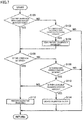
- the concentration conversion processing circuit 46 performs a calibration process illustrated in Fig. 7 .
- step (hereinafter referred to as "S") 100 the concentration conversion processing circuit 46 determines whether the first calibration processing has already been performed. For example, in a case where a flag indicating that the first calibration processing has already been performed is ON, the concentration conversion processing circuit 46 determines that the first calibration processing has already been performed. It is determined that the first calibration processing has already been performed (YES in S100), the process proceeds to S106. If not (NO in S100), the process proceeds to S102.
- the concentration conversion processing circuit 46 determines whether conditions for execution of the first calibration processing are satisfied.
- Conditions for execution of the first calibration processing include, for example, a condition that a period of time determined in advance has elapsed from first use, but may include another condition (for example, a temperature condition) in addition to or instead of this condition.
- the process proceeds to S104. If not (NO in S102), the process ends.
- the concentration conversion processing circuit 46 performs the first calibration processing.
- the calibration processing has been described in detail above, and the detailed description thereof will not therefore be repeated.
- the concentration conversion processing circuit 46 sets a flag indicating that the first calibration processing has already been performed to ON.
- the concentration conversion processing circuit 46 calculates the gas concentration C x using the post-calibration second calibration curve (represented by the above-described Equation 9).
- the concentration conversion processing circuit 46 determines whether a time condition is satisfied. More specifically, the concentration conversion processing circuit 46 determines whether a time condition that a period of time determined in advance has elapsed from the execution of the first calibration processing or the satisfaction of the last time condition is satisfied. In a case where it is determined that a time condition is satisfied (YES in S106), the process proceeds to S112. If not (NO in S106), the process proceeds to S108.
- the concentration conversion processing circuit 46 determines whether a temperature change condition is satisfied.
- the concentration conversion processing circuit 46 determines that a temperature change condition is satisfied in a case where the difference between a temperature at which the last calibration processing has been performed and a current temperature is larger than or equal to a threshold value. In a case where it is determined that a temperature change condition is satisfied (YES in S108), the process proceeds to S110. If not (NO in S108), the process ends.
- the concentration conversion processing circuit 46 determines whether there is the available calibration factor R in the history of the previously calculated calibration factors R. More specifically, the concentration conversion processing circuit 46 determines whether, in the history of the previously calculated calibration factors R, there is a calibration factor R satisfying conditions that a current temperature is in a predetermined temperature range from a temperature at which the calibration factor R has been calculated (a range from an upper limit obtained by adding a predetermined value to the temperature at the time of calculation to a lower limit obtained by subtracting the predetermined value from the temperature at the time of calculation) and a period of time elapsed from the calculation of the calibration factor R is within a validity period of time. In a case where it is determined that there is the available calibration factor R in the history of the previously calculated calibration factors R (YES in S110), the process proceeds to S114. If not (NO in S110), the process proceeds to S112.
- the concentration conversion processing circuit 46 performs the calibration processing.
- the concentration conversion processing circuit 46 updates the calibration factor R using the calibration factor R determined to be available. In a case where there are calibration factors R determined to be available, the concentration conversion processing circuit 46 may update the calibration factor R using the immediately preceding calibration factor R or the calibration factor R calculated at a temperature closest to a current temperature.
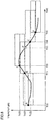
- points A to F are updating points of the calibration factor R. Rectangular regions that include respective points A to F as median values of left ends represent validity ranges of the calibration factor R calculated at corresponding points.
- the first calibration processing is performed (S104) (a point A).
- an environmental temperature decreases.
- T(3) before a period of time determined in advance has elapsed from the time T(1), in a case where the difference between a temperature Th(1) at the time of execution of the last calibration processing (the time T(2)) and the current temperature Th is larger than or equal to the threshold value (YES in S108), it is determined whether there is the available calibration factor R in the history of the previously calculated calibration factors R (S110). In a case where a current temperature and a current time are within a validity range of the calibration factor R calculated at the time T(1)(the point B), it is determined that there is the available calibration factor R (YES in S110) and the calibration factor R is updated using the calibration factor R calculated at the point B (S114) (a point D).
- the calibration processing is performed (S112) (a point E). After that, an environmental temperature further decreases.
- a time T(5) before a period of time determined in advance has elapsed from the time T(4) in a case where the difference between a temperature Th(2) at the time of execution of the last calibration processing (the time T(4)) and a current temperature Th is larger than or equal to the threshold value (YES in S108) and there is no calibration factor R in the history of the previously calculated calibration factors R (NO in S110), the calibration processing is performed (S112) (a point F).
- the gas concentration detection apparatus 10 calculates the calibration factor R using the third calibration curve and the above-described Equation 8 and can appropriately calibrate the second calibration curve using the calculated calibration factor R.
- the deterioration in detection accuracy of a gas concentration can therefore be suppressed. It is therefore possible to provide a gas concentration detection apparatus that appropriately calibrates a changed output characteristics and a gas concentration calculation method for a gas concentration detection apparatus.
- the calibration factor R with which the second calibration curve can be appropriately calibrated irrespective of a concentration at the time of calibration can be calculated.
- the output characteristics of the gas concentration detection apparatus 10 can be appropriately calibrated.
- the second calibration curve cannot be appropriately calibrated using the calibration factor R calculated before the change in some cases.
- the calibration factor R corresponding to the changed temperature can be calculated.
- the second calibration curve can therefore be appropriately calibrated.
- the need to recalculate a calibration factor is eliminated.
- the execution of unnecessary calibration processing can therefore be suppressed, and the execution of calibration processing with good frequency can be achieved.
- the reduction in the execution frequency of the calibration processing leads to the reduction in power consumption at the time of switching by the switcher 32.
- concentration detection target gas of the gas concentration detection apparatus 10 is carbon dioxide.
- detection target gas is not limited to carbon dioxide, and may be, for example, carbon monoxide, CH 4 , or NO x .
- the first wavelength band is selected on the basis of a wavelength band based on the type of the concentration detection target gas (that is, a wavelength at which the absorptance of the concentration detection target gas is high).
- a switcher mechanically switches between filters by placing a first band pass filter or a second band pass filter on an optical path between a light source and a pyroelectric sensor in accordance with a control signal transmitted from a switching driving circuit.
- the number of filters is not limited two, and any filter capable of, on an optical path, selecting and passing one of a first wavelength band in which the infrared radiation absorptance of detection target gas is higher than that in another wavelength band and a second wavelength band in which the infrared radiation absorptance of detection target gas is lower than that in the first wavelength band may be used.
- a Fabry-Perot filter for electrically switching between filters may be placed on an optical path between a light source and a pyroelectric sensor instead of the first band pass filter and the second band pass filter.
- the gas concentration detection apparatus 10 may use voltage values (thermistor output voltages V th ) at a plurality of types of temperatures obtained in advance in a criterion concentration by experiments. That is, the criterion output value V 0 may be calculated on the basis of the thermistor output voltage V th . In the above-described Equations 4 and 5, Th may be therefore replaced with V th .
- the conversion factor C has temperature dependence in accordance with the third calibration curve.
- the conversion factor C may be a value determined in advance.
- the configuration of the gas concentration detection apparatus 10 illustrated in Fig. 1 is illustrative only, and the configuration of the gas concentration detection apparatus 10 is not limited to the configuration illustrated in Fig. 1 .
- circuit configuration of the gas concentration detection apparatus 10 illustrated in Fig. 3 is illustrative only, and the circuit configuration of the gas concentration detection apparatus 10 is not limited to the circuit configuration illustrated in Fig. 3 .
- a criterion temperature determined in advance is 25°C in this embodiment, but may be another temperature.
- the output values of the pyroelectric sensor 24 corresponding to a plurality of temperatures (0°C, 10°C, 25°C, 40°C, and 50°C) in a criterion concentration are obtained in advance by, for example, experiments.
- the criterion output values V0 and the reference output values V ref corresponding to a plurality of temperatures (0°C, 10°C, 25°C, 40°C, and 50°C) in a criterion concentration are obtained in advance by, for example, experiments.
- a plurality of temperatures may include another temperature other than the above-described temperatures.
- the second calibration curve in the calibration processing, is calibrated on the basis of the change in output characteristics from the factory-default second calibration curve.
- the second calibration curve may be calibrated on the basis of the change in output characteristics from the second calibration curve obtained after the last calibration processing.
- the reference output value V ref is a concentration output value in a criterion concentration in a case where the second band pass filter 36 is selected.
- the reference output value V ref since the reference output value V ref is not affected by the absorption of detection target gas, there is no need to set the reference output value V ref on the basis of a concentration output value in a criterion concentration.
- the reference output value V ref may be set irrespective of concentration. The above-described modifications may be implemented in whole or in part.
- a gas concentration detection apparatus according to the second embodiment will be described.
- a gas concentration detection apparatus according to this embodiment is the same as the gas concentration detection apparatus 10 according to the first embodiment except for the operation of the concentration conversion processing circuit 46.
- the same parts are denoted with the same reference signs. Their functions are also the same. Therefore, detailed descriptions thereof will not be repeated.
- the second calibration curve is calibrated using the third calibration curve indicating the relationship between a conversion factor and a temperature output value.
- a fourth calibration curve is additionally provided, and the second calibration curve is calibrated using the fourth calibration curve instead of the third calibration curve.
- the fourth calibration curve indicates the relationship between the thermistor temperature Th and a reference output value V 0r .
- the fourth calibration curve is set by deriving an approximation of a predetermined order on the basis of the output values of the pyroelectric sensor 24, which have been acquired in advance, corresponding one-to-one to a plurality of temperatures of carbon dioxide in a case where the second band pass filter 36 is selected.
- the fourth calibration curve is represented by the following equation.
- V 0 r g ref Th
- g ref represents a function of a predetermined order.
- V 0r d 1 ⁇ Th N + d 2 ⁇ Th N ⁇ 1 + ⁇ + d N + 1
- d 1 to d N+1 are calculated on the basis of the combination of each of a plurality of types of temperatures (the thermistor temperatures Th) and the output value of the pyroelectric sensor 24 which has been acquired in advance by, for example, experiments in a case where the second band pass filter 36 is selected.
- the output values of the pyroelectric sensor 24 corresponding one-to-one to a plurality of temperatures (0°C, 10°C, 25°C, 40°C, and 50°C) are obtained in advance by, for example, experiments, and d 1 to d N+1 are calculated on the basis of the obtained output values.
- Equation 11 and the calculated values of d 1 to d N+1 are stored in a storage medium such as a memory provided in the driving circuit 40.
- the concentration conversion processing circuit 46 calculates the calibration factor R using the fourth calibration curve.
- the calibration factor R is calculated using the above-described Equation 8.
- the calibration factor R is calculated using the following equation in which V 0r represents a factory-default reference output value and V 0r ' represents a reference output value at the time of calibration.
- V 0r represents a factory-default reference output value
- V 0r ' represents a reference output value at the time of calibration.
- the calibration factor R calculated using the above-described Equation 12 is practically the same as the calibration factor R calculated using the above-described Equation 8.
- Vor' is a concentration output value in a case where the second band pass filter 36 is selected.
- the concentration conversion processing circuit 46 calibrates the second calibration curve using the calculated calibration factor R. Specifically, the above-described Equation 9 is used as a post-calibration second calibration curve.
- the gas concentration detection apparatus 10 calculates the calibration factor R using the fourth calibration curve and the above-described Equation 12 and can appropriately calibrate the second calibration curve using the calculated calibration factor R.
- the deterioration in detection accuracy of a gas concentration can therefore be suppressed. It is therefore possible to provide a gas concentration detection apparatus that appropriately calibrates a changed output characteristics and a gas concentration calculation method for a gas concentration detection apparatus.
- the calibration factor R with which the second calibration curve can be appropriately calibrated irrespective of a concentration at the time of calibration can be calculated.
Landscapes
- Physics & Mathematics (AREA)
- Spectroscopy & Molecular Physics (AREA)
- General Physics & Mathematics (AREA)
- Chemical & Material Sciences (AREA)
- Engineering & Computer Science (AREA)
- Health & Medical Sciences (AREA)
- Life Sciences & Earth Sciences (AREA)
- Analytical Chemistry (AREA)
- Biochemistry (AREA)
- General Health & Medical Sciences (AREA)
- Immunology (AREA)
- Pathology (AREA)
- Power Engineering (AREA)
- Combustion & Propulsion (AREA)
- Food Science & Technology (AREA)
- Medicinal Chemistry (AREA)
- Mathematical Physics (AREA)
- Theoretical Computer Science (AREA)
- Investigating Or Analysing Materials By Optical Means (AREA)
Abstract
Description
- The present invention relates to a gas concentration detection apparatus that is configured to calibrate a calibration curve used for the detection of a gas concentration in consideration of a change in output characteristics and a gas concentration calculation method for a gas concentration detection apparatus.
- For example, there is a known technique for causing a nondispersive infrared (NDIR) gas concentration detection apparatus to detect the concentration of detection target gas on the basis of the infrared absorption amount of the gas. Japanese Unexamined Patent Application Publication No.
2013-76634 - Patent Document 1: Japanese Unexamined Patent Application Publication No.
2013-76634 - In the above-described gas concentration detection apparatus, an optical path is formed with a reflection member to increase the optical path length of infrared radiation. In such a gas concentration detection apparatus, after a long period of time has elapsed from the start of use, the reflection factor of infrared radiation from the inner wall of the reflection member forming the optical path is reduced because of a decrease in the output of a light source and the influences of dust and oxidation. Such a gas concentration detection apparatus converts the output characteristics of a concentration detection unit into the concentration of measurement target gas using a calibration curve stored in advance in a memory at the time of the start of use (for example, at the time of shipment). In a case where the above-described reduction in a reflection factor occurs, the concentration of measurement target gas calculated from the output characteristics of the concentration detection unit deviates from the actual concentration of measurement target gas. In the case of the technique disclosed in
Patent Document 1, it is necessary to manually replace a sensor unit to appropriately calibrate a change in output characteristics. This replacement is usually complicated. However, the appropriate calibration of the change in output characteristics cannot be achieved without the replacement of the sensor unit. - It is an object of the present invention to provide a gas concentration detection apparatus for easily calibrating output characteristics deviated from a value to be originally detected and a gas concentration calculation method for a gas concentration detection apparatus. Solution to Problem
- A gas concentration calculation method according to the present invention is for a gas concentration detection apparatus that includes a light source configured to emit infrared radiation, a light-receiving sensor configured to receive the infrared radiation emitted from the light source and output a first output value corresponding to an amount of light received, a reflection member that is provided between the light source and the light-receiving sensor and is configured to form an optical path of the infrared radiation, and a filter configured to, on the optical path, select and pass one of a first wavelength band in which infrared radiation absorptance of detection target gas is higher than that in another wavelength band and a second wavelength band in which infrared radiation absorptance of detection target gas is lower than that in the first wavelength band, and a temperature sensor configured to output a second output value corresponding to a temperature of the gas. The gas concentration calculation method includes the following four steps, a step of determining in advance the first output value obtained when the filter passes infrared radiation in the first wavelength band, a first calibration curve indicating a relationship between a concentration of the gas at a criterion temperature and a value obtained by normalizing the first output value with a criterion output value, and a second calibration curve indicating a relationship between the second output value in a criterion concentration and the criterion output value, a step of calculating a calibration factor used to calibrate the second calibration curve on the basis of the first output value obtained when the filter passes infrared radiation in the second wavelength band, a step of calibrating the second calibration curve on the basis of the calibration factor, and a step of calculating a concentration of the gas on the basis of the first calibration curve and the calibrated second calibration curve.
- Thus, by calculating a calibration factor and calibrating the second calibration curve using the calculated calibration factor, the deterioration in detection accuracy of a gas concentration can be suppressed even in a case where the output characteristics of a gas concentration detection apparatus changes because of the deterioration of a component in the gas concentration detection apparatus.
- The calibration factor calculating step preferably includes a step of calculating a conversion factor representing a ratio of a criterion output value, which is the first output value in the criterion concentration when the filter passes infrared radiation in the first wavelength band, to a reference output value, which is the first output value in the criterion concentration when the filter passes infrared radiation in the second wavelength band, and a step of calculating the calibration factor on the basis of the second output value, the reference output value, and the conversion factor.
- Thus, since the calibration factor can be calculated on the basis of the second output value, the reference output value, and the conversion factor, the second calibration curve can be appropriately calibrated.
- In the conversion factor calculating step, the conversion factor corresponding to the second output value in the criterion concentration is preferably calculated on the basis of a third calibration curve determined in advance.
- Thus, since a conversion factor corresponding to the second output value can be calculated on the basis of the third calibration curve, the second calibration curve can be appropriately calibrated.
- The calibration factor calculating step preferably includes a step of calculating a reference output value corresponding to the second output value obtained when the filter passes infrared radiation in the second wavelength band using a fourth calibration curve determined in advance and a step of calculating, as the calibration factor, a ratio of the reference output value to the first output value obtained when the filter passes infrared radiation in the second wavelength band.
- Thus, since the ratio of the reference output value to the first output value obtained when the filter passes infrared radiation in the second wavelength band can be calculated as the calibration factor, the second calibration curve can be appropriately calibrated using the calculated calibration factor.
- A gas concentration detection apparatus according to the present invention includes a light source configured to emit infrared radiation, a light-receiving sensor configured to receive the infrared radiation emitted from the light source and output a first output value corresponding to an amount of light received, a reflection member that is provided between the light source and the light-receiving sensor and is configured to form an optical path of the infrared radiation, a filter configured to, on the optical path, select and pass one of a first wavelength band in which infrared radiation absorptance of detection target gas is higher than that in another wavelength band and a second wavelength band in which infrared radiation absorptance of detection target gas is lower than that in the first wavelength band, a temperature sensor configured to output a second output value corresponding to a temperature of the gas, and a calculation unit configured to calculate a concentration of gas on the optical path. The first output value obtained when the filter passes infrared radiation in the first wavelength band, a first calibration curve indicating a relationship between a concentration of the gas at a criterion temperature and a value obtained by normalizing the first output value with a criterion output value, and a second calibration curve indicating a relationship between the second output value in a criterion concentration and the criterion output value are determined in advance. The calculation unit calculates a calibration factor used to calibrate the second calibration curve on the basis of the first output value obtained when the filter passes infrared radiation in the second wavelength band, calibrates the second calibration curve on the basis of the calibration factor, and calculates a concentration of the gas on the basis of the first calibration curve and the calibrated second calibration curve.
- Thus, by calculating a calibration factor and calibrating the second calibration curve using the calculated calibration factor, the deterioration in detection accuracy of a gas concentration can be suppressed even in a case where the output characteristics of a gas concentration detection apparatus changes because of the deterioration of a component in the gas concentration detection apparatus.
- The calculation units preferably calculates a conversion factor representing a ratio of a criterion output value, which is the first output value in the criterion concentration when the filter passes infrared radiation in the first wavelength band, to a reference output value, which is the first output value in the criterion concentration when the filter passes infrared radiation in the second wavelength band, and preferably calculates the calibration factor on the basis of the second output value, the reference output value, and the conversion factor.
- Thus, since the calibration factor can be calculated on the basis of the second output value, the reference output value, and the conversion factor, the second calibration curve can be appropriately calibrated.
- The calculation unit preferably calculates the conversion factor corresponding to the second output value in the criterion concentration on the basis of a third calibration curve determined in advance.
- Thus, since a conversion factor corresponding to the second output value can be calculated on the basis of the third calibration curve, the second calibration curve can be appropriately calibrated.
- The calculation unit preferably calculates a reference output value corresponding to the second output value obtained when the filter passes infrared radiation in the second wavelength band using a fourth calibration curve determined in advance, and preferably calculates, as the calibration factor, a ratio of the reference output value to the first output value obtained when the filter passes infrared radiation in the second wavelength band.
- Thus, since the ratio of the reference output value to the first output value obtained when the filter passes infrared radiation in the second wavelength band can be calculated as the calibration factor, the second calibration curve can be appropriately calibrated using the calculated calibration factor.
- The calculation unit preferably calculates the calibration factor each time a period of time determined in advance has elapsed.
- Thus, by calculating the calibration factor each time a period of time determined in advance has elapsed, the output characteristics of the gas concentration detection apparatus can be appropriately calibrated.
- The calculation unit preferably recalculates the calibration factor when a change in the second output value from a point in time when the calibration factor has been calculated is larger than or equal to a value determined in advance.
- Thus, even in a case where the change in the second output value from a point in time when the calibration factor has been calculated is larger than or equal to a value determined in advance, the second calibration curve can be appropriately calibrated by recalculating the calibration factor.
- When there is, in a history of previously calculated calibration factors, a calibration factor that satisfies conditions that the calibration factor has been obtained within a validity period of time and a difference between the second output value and the second output value obtained when the calibration factor has been calculated is smaller than a value determined in advance, the second calibration curve is preferably calibrated using the calibration factor.
- Thus, since unnecessary calibration processing is not performed, the execution of calibration processing with good frequency can be achieved. For example, in a case where a switcher is an electric, power consumption can therefore be reduced.
- The present invention can provide a gas concentration detection apparatus for easily calibrating output characteristics deviated from a value to be originally detected and a gas concentration calculation method for a gas concentration detection apparatus.
-
- [
Fig. 1] Fig. 1 is a diagram illustrating the configuration of a gas concentration detection apparatus according to an embodiment of the present invention. - [
Fig. 2] Fig. 2 is a plan view illustrating the configuration of a gas concentration detection apparatus according to an embodiment of the present invention. - [
Fig. 3] Fig. 3 is a diagram illustrating the circuit configuration of a gas concentration detection apparatus according to an embodiment of the present invention. - [
Fig. 4] Fig. 4 is a diagram describing a first calibration curve at a criterion temperature, a second calibration curve in a criterion concentration, and a third calibration curve used for the calibration of the second calibration curve. - [
Fig. 5] Fig. 5 is a diagram illustrating the relationship between a filter temperature and a sensor output value. - [
Fig. 6] Fig. 6 is a diagram illustrating the relationship between a temperature and a conversion factor. - [
Fig. 7] Fig. 7 is a flowchart illustrating a calibration process. - [
Fig. 8] Fig. 8 is a timing chart illustrating an execution model of a calibration process. - Embodiments of the present invention will be described below with reference to the drawings. In the following description, the same parts are denoted with the same reference signs. Their designations and functions are also the same. Therefore, detailed descriptions thereof will not be repeated.
-
Fig. 1 is a diagram illustrating the configuration of a gasconcentration detection apparatus 10 according to this embodiment. - The gas
concentration detection apparatus 10 according to this embodiment is a nondispersive infrared (NDIR) gas sensor. Gas, the concentration of which is detected by the gasconcentration detection apparatus 10 according to this embodiment, is carbon dioxide. - The gas
concentration detection apparatus 10 is used to, for example, control the amount of ventilation on the basis of the concentration of carbon dioxide in a building energy management system (BEMS). - As illustrated in
Fig. 1 , the gasconcentration detection apparatus 10 includes aconcentration detection unit 30 for performing a gas concentration detection operation, athermistor 28 that is a temperature detection unit for detecting the temperature of gas, and a drivingcircuit 40 for performing lighting control of alight source 20 and performing predetermined processing upon a concentration detection signal (a first output value) output from apyroelectric sensor 24 to be described later and a temperature detection signal (a second output value) output from thethermistor 28. Components included in theconcentration detection unit 30 and thethermistor 28 are provided at respective predetermined positions on one surface of acircuit board 12. Components included in the drivingcircuit 40 are provided at respective predetermined positions on the other surface of thecircuit board 12. - The
concentration detection unit 30 includes thelight source 20, a holding table 22, areflection member 23, thepyroelectric sensor 24 that is a light-receiving sensor, and aswitcher 32 for switching between a plurality of types of filters. - The
light source 20 is disposed apart from thepyroelectric sensor 24 by a predetermined distance. Thelight source 20 emits infrared radiation, so that anoptical path 18 is formed between thelight source 20 and thepyroelectric sensor 24. More specifically, infrared radiation emitted from thelight source 20 is reflected by thereflection member 23, so that theoptical path 18 is formed. -
Fig. 2 is a plan view illustrating the configuration of a gas concentration detection apparatus according this embodiment. As illustrated inFig. 2 , thelight source 20 and thepyroelectric sensor 24 do not face each other and are shifted in an up-and-down direction inFig. 2 . Thereflection member 23 is placed inside a cover 14, and has afirst wall surface 23a facing thelight source 20 and asecond wall surface 23b facing thepyroelectric sensor 24. The orientations (angles) of thefirst wall surface 23a and thesecond wall surface 23b are determined in advance so that theoptical path 18, along which infrared radiation emitted from thelight source 20 is directed to thepyroelectric sensor 24, is formed. Infrared radiation emitted from thelight source 20 is partially reflected by thefirst wall surface 23a facing thelight source 20 as represented by theoptical path 18 illustrated inFig. 2 . The infrared radiation reflected by thefirst wall surface 23a is partially directed to thesecond wall surface 23b and is then reflected by thesecond wall surface 23b. The infrared radiation reflected by thesecond wall surface 23b is partially directed to thepyroelectric sensor 24. Thus, theoptical path 18 is formed. - In this embodiment, the
light source 20 is, for example, a filament lamp. Thelight source 20 may be a light emitting diode (LED) on condition that it emits a wavelength including at least the wavelength of infrared radiation. Thelight source 20 is held by the holding table 22 fixed to thecircuit board 12. Thelight source 20 is controlled to flash at predetermined intervals. - Referring back to
Fig. 1 , the holding table 22 has a semielliptical section that opens to thepyroelectric sensor 24. The semielliptical section has a mirror inner surface. Specifically, a part of an elliptical mirror is formed at the holding table 22. Thelight source 20 is placed at the focal position of the semielliptical section of the holding table 22. A part of the elliptical mirror is also formed at thereflection member 23. Accordingly, infrared radiation emitted from thelight source 20 directly enters thepyroelectric sensor 24 after passing through theoptical path 18, or enters thepyroelectric sensor 24 after being reflected by the mirror surfaces formed at the holding table 22 and the reflection member. - The
pyroelectric sensor 24 is pyroelectric infrared sensor using bulk ceramics. At thepyroelectric sensor 24, anentrance window 26 for receiving infrared radiation emitted from thelight source 20 is formed so that it faces thelight source 20. - The
switcher 32 is provided between thelight source 20 and thepyroelectric sensor 24. Theswitcher 32 places a firstband pass filter 34 or a secondband pass filter 36 on the optical path between thelight source 20 and the pyroelectric sensor in accordance with a control signal transmitted from aswitching driving circuit 48 to be described later. Theswitcher 32 switches between the firstband pass filter 34 and the secondband pass filter 36 using, for example, an actuator such as a motor. The firstband pass filter 34 corresponds to a first filter in claims, and the secondband pass filter 36 corresponds to a second filter in claims. - The first
band pass filter 34 passes infrared radiation in a first wavelength band including a wavelength near 4.26 µm at which the absorptance of carbon dioxide is high. In a case where theswitcher 32 places the firstband pass filter 34 on the optical path, thepyroelectric sensor 24 receives infrared radiation in the first wavelength band that is part of infrared radiation emitted from thelight source 20. A value output from thepyroelectric sensor 24 is converted into the concentration of carbon dioxide. - The second
band pass filter 36 passes infrared radiation in a second wavelength band that is different from the first wavelength band and includes a wavelength (for example, 3.9 µm) at which the absorptance of detection target gas is low. In a case where theswitcher 32 places the secondband pass filter 36 on the optical path, thepyroelectric sensor 24 receives infrared radiation in the second wavelength band that is part of infrared radiation emitted from thelight source 20. - The
thermistor 28 is disposed near thepyroelectric sensor 24 and is fixed to thecircuit board 12. Upon the application of a voltage from the drivingcircuit 40, a constant current flows through thethermistor 28. The drivingcircuit 40 detects a voltage generated when the constant current flows through thethermistor 28 as an output voltage. - The cover 14 covers the components in the
concentration detection unit 30 and thethermistor 28 and is fixed to thecircuit board 12. The cover 14 has anopening 16 from which gas is externally input or emitted. At theopening 16, an air filter is disposed. - The gas
concentration detection apparatus 10 detects the concentration of carbon dioxide in a state where gas is input into the inside of the cover 14 from theopening 16. When infrared radiation is emitted from thelight source 20 to thepyroelectric sensor 24, thepyroelectric sensor 24 receives the emitted infrared radiation and outputs a voltage based on the amount of infrared radiation received. - In a case where the first
band pass filter 34 is placed on the optical path, a voltage output from thepyroelectric sensor 24 changes depending on the concentration of carbon dioxide on theoptical path 18. The reason for this is that part of infrared radiation emitted from thelight source 20, which is in the first wavelength band and is to pass through the firstband pass filter 34, is absorbed by carbon dioxide on theoptical path 18. The amount of infrared radiation that is emitted from thelight source 20 and reaches thepyroelectric sensor 24 via the firstband pass filter 34 therefore changes (the Lambert-Beer law). - In a case where the second
band pass filter 36 is placed on the optical path, a voltage output from thepyroelectric sensor 24 does not change depending on the concentration of carbon dioxide on theoptical path 18. The reason for this is that part of infrared radiation emitted from thelight source 20, which is in the second wavelength band and is to pass through the second band pass filter, is poorly absorbed by carbon dioxide or another gas. - On the other hand, irrespective of which of the first
band pass filter 34 and the secondband pass filter 36 is placed on the optical path, a voltage output from thepyroelectric sensor 24 changes in accordance with a temperature. -
Fig. 3 is a diagram illustrating the circuit configuration of the gasconcentration detection apparatus 10 according to this embodiment. As illustrated inFig. 3 , the drivingcircuit 40 includes anamplification circuit 42, an A/D conversion circuit 44, a concentrationconversion processing circuit 46, and theswitching driving circuit 48. The concentrationconversion processing circuit 46 corresponds to a calculation unit in claims. - The
amplification circuit 42 is, for example, an amplifier, and amplifies the strength of a concentration detection signal (the first output value) output from thepyroelectric sensor 24 and the strength of a temperature detection signal (the second output value) output from thethermistor 28. - The A/
D conversion circuit 44 converts an analog signal, which has been subjected to signal strength amplification in theamplification circuit 42, into a digital signal. The amplification of a signal strength and the conversion of an analog signal into a digital signal may be performed using known techniques. - The concentration
conversion processing circuit 46 performs predetermined processing upon a digital signal converted by the A/D conversion circuit 44 to calculate a carbon dioxide concentration Cx in gas input into the inside of the cover 14. In this embodiment, the concentrationconversion processing circuit 46 is realized by, for example, a central processing unit (CPU). A CPU executes a program stored in a memory (not illustrated) to perform predetermined computation processing and predetermined control processing. For example, a CPU performs not only computation processing for calculating the concentration of carbon dioxide but also control processing for turning on thelight source 20, control processing for applying a voltage to thethermistor 28, and control processing for operating theswitcher 32 to place either the firstband pass filter 34 or the secondband pass filter 36 on the optical path between thelight source 20 and thepyroelectric sensor 24. A CPU outputs a driving instruction to theswitching driving circuit 48 when operating theswitcher 32. Upon receiving the driving instruction from the CPU, theswitching driving circuit 48 generates a control signal and outputs the control signal to theswitcher 32. - In this embodiment, the gas
concentration detection apparatus 10 detects the concentration of carbon dioxide using the following procedure. It is assumed that theswitcher 32 selects the first band pass filter 34 (that is, the firstband pass filter 34 is placed on the optical path). - (1) Acquiring a temperature detection signal from the
thermistor 28. (2) Turning on thelight source 20. (3) Acquiring an output value V of thepyroelectric sensor 24. (4) Performing predetermined signal processing upon the output value V of thepyroelectric sensor 24. - The output value V of the
pyroelectric sensor 24 corresponds to the first output value according to the present invention. A temperature detection signal output from thethermistor 28 corresponds to the second output value according to the present invention. - The predetermined signal processing includes, for example, processing for removing noise from the output waveform of the
pyroelectric sensor 24 using the method of moving averages, processing for causing theamplification circuit 42 to amplify a signal strength, and processing for causing the A/D conversion circuit 44 to obtain digital data by conversion. These pieces of processing are also performed upon a temperature detection signal. On the basis of a temperature detection signal, a thermistor temperature Th[K] is calculated. The calculation of the thermistor temperature Th may be performed in (1) in the above-described procedure. - (5) Calculating the carbon dioxide concentration Cx on the basis of the thermistor temperature Th and the output value V of the
pyroelectric sensor 24. (6) Turning off thelight source 20. The gasconcentration detection apparatus 10 performs the procedure from (1) to (6), for example, at regular time intervals. - A method of causing the gas
concentration detection apparatus 10 according to this embodiment to calculate the carbon dioxide concentration Cx on the basis of the temperature Th of thethermistor 28 and the output value V of thepyroelectric sensor 24. - The concentration
conversion processing circuit 46 calculates the concentration of carbon dioxide on the basis of the output value V of thepyroelectric sensor 24 and the first and second calibration curves acquired in advance. - Data of the first calibration curve and data of the second calibration curve are acquired in advance at the time of manufacture of the gas
concentration detection apparatus 10 and are stored in a storage medium such as a memory in the drivingcircuit 40. - The first calibration curve indicates the relationship between the carbon dioxide concentration Cx and the output value V of the
pyroelectric sensor 24 at a criterion temperature (25°C) determined in advance. More specifically, the first calibration curve indicates the relationship between a value (V/V0) obtained by normalizing the output value V of thepyroelectric sensor 24 with a criterion output value V0 and the carbon dioxide concentration Cx. A first calibration curve is set by deriving an approximation of a predetermined order on the basis of the output values of thepyroelectric sensor 24, which have been acquired in advance, corresponding one-to-one to a plurality of concentrations of carbon dioxide at a criterion temperature. - This criterion output value V0 is the output value of the
pyroelectric sensor 24 corresponding to the thermistor temperature Th in a case where the concentration of carbon dioxide is a criterion concentration (e.g. 0 ppm) determined in advance. The criterion output value V0 is calculated on the basis of the thermistor temperature Th using the second calibration curve to be described later. - In this embodiment, the first calibration curve is represented by the following equation.

- In the above-described
Equation 1, f represents a function of a predetermined order, and may be, for example, a quadratic function or a cubic function. In a case where f represents an Nth-order function, the gas concentration Cx is represented by the following equation.
- In the above-described
Equation 2, a1 to aN+1 are calculated on the basis of the combination of each of a plurality of types of concentrations of carbon dioxide and the output value of thepyroelectric sensor 24 which has been acquired in advance by, for example, experiments at a criterion temperature. For example, as illustrated inFig. 4 , the output values of thepyroelectric sensor 24 corresponding one-to-one to a plurality of concentrations of carbon dioxide (for example, 0 ppm, 400 ppm, 1000 ppm, and 2000 ppm) determined in advance at a criterion temperature are acquired in advance by, for example, experiments, and a1 to aN+1 are calculated on the basis of the acquired output values. - The above-described
Equation 2 and the calculated values of a1 to aN+1 are stored in a storage medium such as a memory provided in the drivingcircuit 40. - The thermistor temperature Th is calculated using the following equation.

- In the above-described
Equation 3, B represents a constant, Vth represents the output voltage of thethermistor 28, Vcc represents a voltage applied from the drivingcircuit 40 to thethermistor 28, and Th25 represents a thermistor temperature [K] at 25°C. The above-describedEquation 3 and the constant B are stored in a storage medium such as a memory provided in the drivingcircuit 40. - The concentration
conversion processing circuit 46 calculates the criterion output value V0 using the second calibration curve. The second calibration curve indicates the relationship between the thermistor temperature Th and the criterion output value V0 in a criterion concentration (for example, 0 ppm) determined in advance. A second calibration curve is set by deriving an approximation of a predetermined order on the basis of the output values of thepyroelectric sensor 24, which have been acquired in advance, corresponding one-to-one to a plurality of temperatures of carbon dioxide in a criterion concentration in a case where the firstband pass filter 34 is selected. - In this embodiment, the second calibration curve is represented by the following equation.

- In the above-described
Equation 4, g represents a function of a predetermined order. In a case where g represents an Nth-order function, the criterion output value V0 is represented by the following equation.
- In the above-described
Equation 5, b1 to bN+1 are calculated on the basis of the combination of each of a plurality of types of temperatures (the thermistor temperatures Th) and the output value of thepyroelectric sensor 24 which has been acquired in advance by, for example, experiments in a criterion concentration in a case where the firstband pass filter 34 is selected. - As illustrated in
Fig. 4 , the output values of thepyroelectric sensor 24 corresponding one-to-one to a plurality of temperatures (0°C, 10°C, 25°C, 40°C, and 50°C) in a criterion concentration are acquired in advance by, for example, experiments, and b1 to bN+1 are calculated on the basis of the acquired output values. - The above-described
Equation 5 and the calculated values of b1 to bN+1 are stored in a storage medium such as a memory provided in the drivingcircuit 40. - In this embodiment, the concentration
conversion processing circuit 46 calibrates the second calibration curve. More specifically, a third calibration curve represented by a broken-line arrow inFig. 4 is acquired and the second calibration curve is calibrated using the third calibration curve. The third calibration curve is calculated on the basis of the thermistor temperature Th and the ratio (hereinafter referred to as a conversion factor C) of an concentration output value (criterion output value V0) in a criterion concentration when the firstband pass filter 34 is selected to a concentration output value (hereinafter referred to as a reference output value Vref) in the criterion concentration when the secondband pass filter 36 is selected. A third calibration curve is set by deriving an approximation of a predetermined order on the basis of the output values of thepyroelectric sensor 24, which have been acquired in advance, corresponding one-to-one to a plurality of temperatures of carbon dioxide in a criterion concentration. - In this embodiment, the third calibration curve is represented by the following equation.

- Since the criterion output value V0 and the reference output value Vref are functions in which Th serves as a variable, they can be represented as a single function in which Th serves as a variable as expressed by the above-described Equation 6. In Equation 6, h represents a function of a predetermined order. For example, in a case where h is an Nth-order function, the conversion factor C is represented by the following equation.

- In the above-described Equation 7, c1 to cN+1 are calculated on the basis of the combination of each of a plurality of types of temperatures (the thermistor temperatures Th), the output value (criterion output value) of the
pyroelectric sensor 24 when the firstband pass filter 34 is selected, and the output value (reference output value) of thepyroelectric sensor 24 when the secondband pass filter 36 is selected which has been acquired in advance in a criterion concentration by, for example, experiments. - For example, as illustrated in
Fig. 5 , the criterion output values V0 and the reference output values Vref corresponding one-to-one to a plurality of temperatures (0°C, 10°C, 25°C, 40°C, and 50°C) in a criterion concentration are acquired in advance by, for example, experiments, and c1 to cN+1 are calculated on the basis of the acquired output values. InFig. 5 , a vertical axis represents the first output value of thepyroelectric sensor 24 and a horizontal axis represents a temperature. - The above-described Equation 7 and the calculated values of c1 to cN+1 are stored in a storage medium such as a memory provided in the driving
circuit 40. - As illustrated in
Fig. 6 , the higher the temperature, the smaller the conversion factor C represented by the third calibration curve. InFig. 6 , a vertical axis represents the conversion factor C and a horizontal axis represents a temperature. - The concentration
conversion processing circuit 46 calculates a factor (hereinafter referred to as a calibration factor R) used to calibrate the second calibration curve using the third calibration curve. - The calibration factor R is defined by the following equation in which V0 represents a factory-default criterion output value and V0' represents a criterion output value at the time of calibration.

- The value of V0 is calculated by the equation of V0 = g(ThNew) using the second calibration curve and a thermistor temperature ThNew at the time of calibration. On the other hand, V0' is a concentration output value in a criterion concentration at the time of calibration in a case where the first
band pass filter 34 is selected. In an actual environment at the time of calibration, since a criterion concentration is not always achieved, V0' is calculated by the equation of V0' = Vref × C. The above-described Equation 8 is therefore rewritten as R = Vref × C/g(ThNew). Since the conversion factor C is defined by the above-described Equation 6, the calibration factor R can be calculated irrespective of a gas concentration at the time of calibration. - In a case where the calibration factor R is calculated, the concentration
conversion processing circuit 46 calibrates the second calibration curve using the calculated calibration factor R. Specifically, the following equation is used as a post-calibration second calibration curve.
- After calibration, the concentration
conversion processing circuit 46 uses the above-described Equation 9 instead of the above-describedEquation 4 to calculate the gas concentration Cx. That is, the concentrationconversion processing circuit 46 calculates the criterion output value V0 using the post-calibration second calibration curve represented by the above-described Equation 9 and calculates the gas concentration Cx using the calculated criterion output value V0 and the first calibration curve. - The timing of execution of calibration processing by the concentration
conversion processing circuit 46 will be described below. - The concentration
conversion processing circuit 46 performs first calibration processing, for example, after a predetermined period of time has elapsed from first use. Before performing the first calibration processing, the concentrationconversion processing circuit 46 calculates the criterion output value V0 using the factory-default second calibration curve represented by the above-describedEquation 4. After performing the first calibration processing, the concentrationconversion processing circuit 46 calculates the criterion output value V0 using the post-calibration second calibration curve represented by the above-described Equation 9. After performing the first calibration processing, the concentrationconversion processing circuit 46 performs calibration processing each time a predetermined period of time has elapsed. - Even before a predetermined period of time has elapsed from the execution of the first calibration processing, the concentration
conversion processing circuit 46 performs calibration processing in a case where there is a change (increase or decrease) in environmental temperature from a temperature at the time of execution of the last calibration processing which is larger than or equal to a threshold value. The predetermined period of time is, for example, 24 hours. The threshold value is, for example, ±5°C from a temperature at the time of execution of the last calibration processing. - In this embodiment, the concentration
conversion processing circuit 46 performs a calibration process illustrated inFig. 7 . - Specifically, in step (hereinafter referred to as "S") 100, the concentration
conversion processing circuit 46 determines whether the first calibration processing has already been performed. For example, in a case where a flag indicating that the first calibration processing has already been performed is ON, the concentrationconversion processing circuit 46 determines that the first calibration processing has already been performed. It is determined that the first calibration processing has already been performed (YES in S100), the process proceeds to S106. If not (NO in S100), the process proceeds to S102. - In S102, the concentration
conversion processing circuit 46 determines whether conditions for execution of the first calibration processing are satisfied. Conditions for execution of the first calibration processing include, for example, a condition that a period of time determined in advance has elapsed from first use, but may include another condition (for example, a temperature condition) in addition to or instead of this condition. In a case where it is determined that conditions for execution of the first calibration processing are satisfied (YES in S102), the process proceeds to S104. If not (NO in S102), the process ends. - In S104, the concentration
conversion processing circuit 46 performs the first calibration processing. The calibration processing has been described in detail above, and the detailed description thereof will not therefore be repeated. At that time, the concentrationconversion processing circuit 46 sets a flag indicating that the first calibration processing has already been performed to ON. After performing the first calibration processing, the concentrationconversion processing circuit 46 calculates the gas concentration Cx using the post-calibration second calibration curve (represented by the above-described Equation 9). - In S106, the concentration
conversion processing circuit 46 determines whether a time condition is satisfied. More specifically, the concentrationconversion processing circuit 46 determines whether a time condition that a period of time determined in advance has elapsed from the execution of the first calibration processing or the satisfaction of the last time condition is satisfied. In a case where it is determined that a time condition is satisfied (YES in S106), the process proceeds to S112. If not (NO in S106), the process proceeds to S108. - In S108, the concentration
conversion processing circuit 46 determines whether a temperature change condition is satisfied. The concentrationconversion processing circuit 46 determines that a temperature change condition is satisfied in a case where the difference between a temperature at which the last calibration processing has been performed and a current temperature is larger than or equal to a threshold value. In a case where it is determined that a temperature change condition is satisfied (YES in S108), the process proceeds to S110. If not (NO in S108), the process ends. - In S110, the concentration
conversion processing circuit 46 determines whether there is the available calibration factor R in the history of the previously calculated calibration factors R. More specifically, the concentrationconversion processing circuit 46 determines whether, in the history of the previously calculated calibration factors R, there is a calibration factor R satisfying conditions that a current temperature is in a predetermined temperature range from a temperature at which the calibration factor R has been calculated (a range from an upper limit obtained by adding a predetermined value to the temperature at the time of calculation to a lower limit obtained by subtracting the predetermined value from the temperature at the time of calculation) and a period of time elapsed from the calculation of the calibration factor R is within a validity period of time. In a case where it is determined that there is the available calibration factor R in the history of the previously calculated calibration factors R (YES in S110), the process proceeds to S114. If not (NO in S110), the process proceeds to S112. - In S112, the concentration
conversion processing circuit 46 performs the calibration processing. In S114, the concentrationconversion processing circuit 46 updates the calibration factor R using the calibration factor R determined to be available. In a case where there are calibration factors R determined to be available, the concentrationconversion processing circuit 46 may update the calibration factor R using the immediately preceding calibration factor R or the calibration factor R calculated at a temperature closest to a current temperature. - An exemplary operation of the gas
concentration detection apparatus 10 in a case where the calibration process illustrated inFig. 7 is performed will be described with reference toFig. 8 . Referring toFig. 8 , points A to F are updating points of the calibration factor R. Rectangular regions that include respective points A to F as median values of left ends represent validity ranges of the calibration factor R calculated at corresponding points. - As a time T(0), in a case where the first calibration processing has not been performed (NO in S100) and conditions for execution of the first calibration processing are satisfied (YES in S102), the first calibration processing is performed (S104) (a point A).
- At a time T(1), in a case where the first calibration processing has already been performed (YES in S100) and a period of time determined in advance has elapsed from the execution of the last calibration processing (YES in S106), the calibration processing is performed (S112) (a point B).
- At a time T(2) before a period of time determined in advance has elapsed from the time T(1) (NO in S106), in a case where the difference between a temperature Th(0) at the time of execution of the last calibration processing (the time T(1)) and a current temperature Th is larger than or equal to a threshold value (YES in S108) and there is no calibration factor R in the history of the previously calculated calibration factors R (NO in S110), the calibration processing is performed (S112) (a point C).
- After that, an environmental temperature decreases. At a time T(3) before a period of time determined in advance has elapsed from the time T(1), in a case where the difference between a temperature Th(1) at the time of execution of the last calibration processing (the time T(2)) and the current temperature Th is larger than or equal to the threshold value (YES in S108), it is determined whether there is the available calibration factor R in the history of the previously calculated calibration factors R (S110). In a case where a current temperature and a current time are within a validity range of the calibration factor R calculated at the time T(1)(the point B), it is determined that there is the available calibration factor R (YES in S110) and the calibration factor R is updated using the calibration factor R calculated at the point B (S114) (a point D).
- At a time T(4) at which a period of time determined in advance has elapsed from the time T(1) (YES in S106), the calibration processing is performed (S112) (a point E). After that, an environmental temperature further decreases. At a time T(5) before a period of time determined in advance has elapsed from the time T(4), in a case where the difference between a temperature Th(2) at the time of execution of the last calibration processing (the time T(4)) and a current temperature Th is larger than or equal to the threshold value (YES in S108) and there is no calibration factor R in the history of the previously calculated calibration factors R (NO in S110), the calibration processing is performed (S112) (a point F).
- Thus, even in a case where the output characteristics of the gas
concentration detection apparatus 10 change because of, for example, the deterioration of a component such as thelight source 20, the gasconcentration detection apparatus 10 according to this embodiment calculates the calibration factor R using the third calibration curve and the above-described Equation 8 and can appropriately calibrate the second calibration curve using the calculated calibration factor R. The deterioration in detection accuracy of a gas concentration can therefore be suppressed. It is therefore possible to provide a gas concentration detection apparatus that appropriately calibrates a changed output characteristics and a gas concentration calculation method for a gas concentration detection apparatus. - Furthermore, by calculating the calibration factor R using the third calibration curve indicating the relationship between the conversion factor C and the thermistor temperature Th, the calibration factor R with which the second calibration curve can be appropriately calibrated irrespective of a concentration at the time of calibration can be calculated.
- Furthermore, by calculating the calibration factor R each time a period of time determined in advance has elapsed, the output characteristics of the gas
concentration detection apparatus 10 can be appropriately calibrated. - Furthermore, in a case where a temperature significantly changes, the second calibration curve cannot be appropriately calibrated using the calibration factor R calculated before the change in some cases. By performing the calibration processing, the calibration factor R corresponding to the changed temperature can be calculated. The second calibration curve can therefore be appropriately calibrated.
- Furthermore, by using the history of calibration factors, the need to recalculate a calibration factor is eliminated. The execution of unnecessary calibration processing can therefore be suppressed, and the execution of calibration processing with good frequency can be achieved. The reduction in the execution frequency of the calibration processing leads to the reduction in power consumption at the time of switching by the
switcher 32. - Modifications will be described below.
- In the above-described embodiment, concentration detection target gas of the gas
concentration detection apparatus 10 is carbon dioxide. However, detection target gas is not limited to carbon dioxide, and may be, for example, carbon monoxide, CH4, or NOx. In a case where a concentration detection target is gas other than carbon dioxide, the first wavelength band is selected on the basis of a wavelength band based on the type of the concentration detection target gas (that is, a wavelength at which the absorptance of the concentration detection target gas is high). - In the above-described embodiment, a switcher mechanically switches between filters by placing a first band pass filter or a second band pass filter on an optical path between a light source and a pyroelectric sensor in accordance with a control signal transmitted from a switching driving circuit. The number of filters is not limited two, and any filter capable of, on an optical path, selecting and passing one of a first wavelength band in which the infrared radiation absorptance of detection target gas is higher than that in another wavelength band and a second wavelength band in which the infrared radiation absorptance of detection target gas is lower than that in the first wavelength band may be used. For example, a Fabry-Perot filter for electrically switching between filters may be placed on an optical path between a light source and a pyroelectric sensor instead of the first band pass filter and the second band pass filter.
- Instead of a plurality of types of temperatures (the thermistor temperatures Th) obtained in advance in a criterion concentration by experiments, the gas
concentration detection apparatus 10 may use voltage values (thermistor output voltages Vth) at a plurality of types of temperatures obtained in advance in a criterion concentration by experiments. That is, the criterion output value V0 may be calculated on the basis of the thermistor output voltage Vth. In the above-describedEquations - In this embodiment, the conversion factor C has temperature dependence in accordance with the third calibration curve. However, in a case where temperature dependence is small, the conversion factor C may be a value determined in advance.
- The configuration of the gas
concentration detection apparatus 10 illustrated inFig. 1 is illustrative only, and the configuration of the gasconcentration detection apparatus 10 is not limited to the configuration illustrated inFig. 1 . - The circuit configuration of the gas
concentration detection apparatus 10 illustrated inFig. 3 is illustrative only, and the circuit configuration of the gasconcentration detection apparatus 10 is not limited to the circuit configuration illustrated inFig. 3 . - A criterion temperature determined in advance is 25°C in this embodiment, but may be another temperature.
- In the above-described embodiment, the output values of the
pyroelectric sensor 24 corresponding to a plurality of temperatures (0°C, 10°C, 25°C, 40°C, and 50°C) in a criterion concentration are obtained in advance by, for example, experiments. Furthermore, in the above-described embodiment, the criterion output values V0 and the reference output values Vref corresponding to a plurality of temperatures (0°C, 10°C, 25°C, 40°C, and 50°C) in a criterion concentration are obtained in advance by, for example, experiments. However, a plurality of temperatures may include another temperature other than the above-described temperatures. - In this embodiment, in the calibration processing, the second calibration curve is calibrated on the basis of the change in output characteristics from the factory-default second calibration curve. However, the second calibration curve may be calibrated on the basis of the change in output characteristics from the second calibration curve obtained after the last calibration processing.
- In this embodiment, the reference output value Vref is a concentration output value in a criterion concentration in a case where the second
band pass filter 36 is selected. However, since the reference output value Vref is not affected by the absorption of detection target gas, there is no need to set the reference output value Vref on the basis of a concentration output value in a criterion concentration. The reference output value Vref may be set irrespective of concentration. The above-described modifications may be implemented in whole or in part. - A gas concentration detection apparatus according to the second embodiment will be described. A gas concentration detection apparatus according to this embodiment is the same as the gas
concentration detection apparatus 10 according to the first embodiment except for the operation of the concentrationconversion processing circuit 46. The same parts are denoted with the same reference signs. Their functions are also the same. Therefore, detailed descriptions thereof will not be repeated. - In the above-described first embodiment, the second calibration curve is calibrated using the third calibration curve indicating the relationship between a conversion factor and a temperature output value. In this embodiment, a fourth calibration curve is additionally provided, and the second calibration curve is calibrated using the fourth calibration curve instead of the third calibration curve.
- The fourth calibration curve indicates the relationship between the thermistor temperature Th and a reference output value V0r. The fourth calibration curve is set by deriving an approximation of a predetermined order on the basis of the output values of the
pyroelectric sensor 24, which have been acquired in advance, corresponding one-to-one to a plurality of temperatures of carbon dioxide in a case where the secondband pass filter 36 is selected. - In this embodiment, the fourth calibration curve is represented by the following equation.

- In the above-described
Equation 10, gref represents a function of a predetermined order. For example, in a case where gref is an Nth-order function, the reference output value V0r is represented by the following equation.
- In the above-described Equation 11, d1 to dN+1 are calculated on the basis of the combination of each of a plurality of types of temperatures (the thermistor temperatures Th) and the output value of the
pyroelectric sensor 24 which has been acquired in advance by, for example, experiments in a case where the secondband pass filter 36 is selected. - For example, the output values of the
pyroelectric sensor 24 corresponding one-to-one to a plurality of temperatures (0°C, 10°C, 25°C, 40°C, and 50°C) are obtained in advance by, for example, experiments, and d1 to dN+1 are calculated on the basis of the obtained output values. - The above-described Equation 11 and the calculated values of d1 to dN+1 are stored in a storage medium such as a memory provided in the driving
circuit 40. - In this embodiment, the concentration
conversion processing circuit 46 calculates the calibration factor R using the fourth calibration curve. - In the above-described first embodiment, the calibration factor R is calculated using the above-described Equation 8. In this embodiment, the calibration factor R is calculated using the following equation in which V0r represents a factory-default reference output value and V0r' represents a reference output value at the time of calibration.

- The calibration factor R calculated using the above-described
Equation 12 is practically the same as the calibration factor R calculated using the above-described Equation 8. - The value of V0r is calculated by the equation of V0r = gref(ThNew) using the fourth calibration curve and the thermistor temperature ThNew at the time of calibration. On the other hand, Vor' is a concentration output value in a case where the second
band pass filter 36 is selected. - In a case where the calibration factor R is calculated, the concentration
conversion processing circuit 46 calibrates the second calibration curve using the calculated calibration factor R. Specifically, the above-described Equation 9 is used as a post-calibration second calibration curve. - The timing of execution of the calibration processing has already been described in the first embodiment with reference to
Figs. 7 and8 , and the detailed description thereof will not be repeated. - Thus, even in a case where the output characteristics of the gas
concentration detection apparatus 10 change because of, for example, the deterioration of a component such as thelight source 20, the gasconcentration detection apparatus 10 according to this embodiment calculates the calibration factor R using the fourth calibration curve and the above-describedEquation 12 and can appropriately calibrate the second calibration curve using the calculated calibration factor R. The deterioration in detection accuracy of a gas concentration can therefore be suppressed. It is therefore possible to provide a gas concentration detection apparatus that appropriately calibrates a changed output characteristics and a gas concentration calculation method for a gas concentration detection apparatus. - By calculating the calibration factor R using the fourth calibration curve, the calibration factor R with which the second calibration curve can be appropriately calibrated irrespective of a concentration at the time of calibration can be calculated.
- It should be understood that the above-described embodiments are illustrative only and are not intended to limit the scope of the present invention. The scope of the present invention should be determined in view of the appended claims. Accordingly, equivalents to the appended claims and all modifications of the present invention which fall within the scope of the present invention are intended to be encompassed in the scope of the present invention. Reference Signs List
-
- 10
- gas concentration detection apparatus
- 12
- circuit board
- 14
- cover
- 16
- opening
- 18
- optical path
- 20
- light source
- 22
- holding table
- 23
- reflection member
- 24
- pyroelectric sensor
- 28
- thermistor
- 30
- concentration detection unit
- 32
- switcher
- 34
- first band pass filter
- 36
- second band pass filter
- 40
- driving circuit
- 42
- amplification circuit
- 44
- A/D conversion circuit
- 46
- concentration conversion processing circuit
- 48
- switching driving circuit
Claims (11)
- A gas concentration calculation method for a gas concentration detection apparatus that includes a light source configured to emit infrared radiation, a light-receiving sensor configured to receive the infrared radiation emitted from the light source and output a first output value corresponding to an amount of light received, a reflection member that is provided between the light source and the light-receiving sensor and is configured to form an optical path of the infrared radiation, and a filter configured to, on the optical path, select and pass one of a first wavelength band in which infrared radiation absorptance of detection target gas is higher than that in another wavelength band and a second wavelength band in which infrared radiation absorptance of detection target gas is lower than that in the first wavelength band, and a temperature sensor configured to output a second output value corresponding to a temperature of the gas, the gas concentration calculation method comprising:a step of determining in advance the first output value obtained when the filter passes infrared radiation in the first wavelength band, a first calibration curve indicating a relationship between a concentration of the gas at a criterion temperature and a value obtained by normalizing the first output value with a criterion output value, and a second calibration curve indicating a relationship between the second output value in a criterion concentration and the criterion output value;a step of calculating a calibration factor used to calibrate the second calibration curve on the basis of the first output value obtained when the filter passes infrared radiation in the second wavelength band;a step of calibrating the second calibration curve on the basis of the calibration factor; anda step of calculating a concentration of the gas on the basis of the first calibration curve and the calibrated second calibration curve.
- The gas concentration calculation method according to Claim 1, wherein the calibration factor calculating step includes,
a step of calculating a conversion factor representing a ratio of a criterion output value, which is the first output value in the criterion concentration when the filter passes infrared radiation in the first wavelength band, to a reference output value, which is the first output value in the criterion concentration when the filter passes infrared radiation in the second wavelength band, and
a step of calculating the calibration factor on the basis of the second output value, the reference output value, and the conversion factor. - The gas concentration calculation method according to Claim 2, wherein, in the conversion factor calculating step, the conversion factor corresponding to the second output value in the criterion concentration is calculated on the basis of a third calibration curve determined in advance.
- The gas concentration calculation method according to Claim 1, wherein the calibration factor calculating step includes,
a step of calculating a reference output value corresponding to the second output value obtained when the filter passes infrared radiation in the second wavelength band using a fourth calibration curve determined in advance, and
a step of calculating, as the calibration factor, a ratio of the reference output value to the first output value obtained when the filter passes infrared radiation in the second wavelength band. - A gas concentration detection apparatus comprising:a light source configured to emit infrared radiation;a light-receiving sensor configured to receive the infrared radiation emitted from the light source and output a first output value corresponding to an amount of light received;a reflection member that is provided between the light source and the light-receiving sensor and is configured to form an optical path of the infrared radiation;a filter configured to, on the optical path, select and pass one of a first wavelength band in which infrared radiation absorptance of detection target gas is higher than that in another wavelength band and a second wavelength band in which infrared radiation absorptance of detection target gas is lower than that in the first wavelength band;a temperature sensor configured to output a second output value corresponding to a temperature of the gas; anda calculation unit configured to calculate a concentration of gas on the optical path,wherein the first output value obtained when the filter passes infrared radiation in the first wavelength band, a first calibration curve indicating a relationship between a concentration of the gas at a criterion temperature and a value obtained by normalizing the first output value with a criterion output value, and a second calibration curve indicating a relationship between the second output value in a criterion concentration and the criterion output value are determined in advance, andwherein the calculation unit calculates a calibration factor used to calibrate the second calibration curve on the basis of the first output value obtained when the filter passes infrared radiation in the second wavelength band, calibrates the second calibration curve on the basis of the calibration factor, and calculates a concentration of the gas on the basis of the first calibration curve and the calibrated second calibration curve.
- The gas concentration detection apparatus according to Claim 5, wherein the calculation units calculates a conversion factor representing a ratio of a criterion output value, which is the first output value in the criterion concentration when the filter passes infrared radiation in the first wavelength band, to a reference output value, which is the first output value in the criterion concentration when the filter passes infrared radiation in the second wavelength band, and calculates the calibration factor on the basis of the second output value, the reference output value, and the conversion factor.
- The gas concentration detection apparatus according to Claim 6, wherein the calculation unit calculates the conversion factor corresponding to the second output value in the criterion concentration on the basis of a third calibration curve determined in advance.
- The gas concentration detection apparatus according to Claim 5, wherein the calculation unit calculates a reference output value corresponding to the second output value obtained when the filter passes infrared radiation in the second wavelength band using a fourth calibration curve determined in advance, and calculates, as the calibration factor, a ratio of the reference output value to the first output value obtained when the filter passes infrared radiation in the second wavelength band.
- The gas concentration detection apparatus according to any one of Claims 5 to 8, wherein the calculation unit calculates the calibration factor each time a period of time determined in advance has elapsed.
- The gas concentration detection apparatus according to any one of Claims 5 to 9, wherein the calculation unit recalculates the calibration factor when a change in the second output value from a point in time when the calibration factor has been calculated is larger than or equal to a value determined in advance.
- The gas concentration detection apparatus according to Claim 10, wherein, when there is, in a history of previously calculated calibration factors, a calibration factor that satisfies conditions that the calibration factor has been obtained within a validity period of time and a difference between the second output value and the second output value obtained when the calibration factor has been calculated is smaller than a value determined in advance, the second calibration curve is calibrated using the calibration factor.
Applications Claiming Priority (2)
| Application Number | Priority Date | Filing Date | Title |
|---|---|---|---|
| JP2014158519 | 2014-08-04 | ||
| PCT/JP2015/071786 WO2016021495A1 (en) | 2014-08-04 | 2015-07-31 | Gas density detection device and gas density calculation method for gas density detection device |
Publications (3)
| Publication Number | Publication Date |
|---|---|
| EP3179233A1 true EP3179233A1 (en) | 2017-06-14 |
| EP3179233A4 EP3179233A4 (en) | 2018-04-25 |
| EP3179233B1 EP3179233B1 (en) | 2019-10-23 |
Family
ID=55263763
Family Applications (1)
| Application Number | Title | Priority Date | Filing Date |
|---|---|---|---|
| EP15829541.0A Active EP3179233B1 (en) | 2014-08-04 | 2015-07-31 | Gas density detection device and gas density calculation method for gas density detection device |
Country Status (3)
| Country | Link |
|---|---|
| EP (1) | EP3179233B1 (en) |
| JP (1) | JP6428779B2 (en) |
| WO (1) | WO2016021495A1 (en) |
Cited By (2)
| Publication number | Priority date | Publication date | Assignee | Title |
|---|---|---|---|---|
| FR3119021A1 (en) * | 2021-01-21 | 2022-07-22 | Elichens | Method for calibrating a gas sensor and method for measuring a gas implementing the calibration |
| US11802700B2 (en) * | 2017-04-06 | 2023-10-31 | Carrier Corporation | Moderate-to-low global warming potential value refrigerant leak detection |
Families Citing this family (2)
| Publication number | Priority date | Publication date | Assignee | Title |
|---|---|---|---|---|
| CN106525700A (en) * | 2016-10-12 | 2017-03-22 | 深圳市计量质量检测研究院 | An online calibration system and calibration method for a xenon lamp aging test chamber |
| CN115165799B (en) * | 2021-04-02 | 2025-03-14 | 中国计量科学研究院 | Motor vehicle exhaust remote sensing system and control method and control device thereof |
Family Cites Families (9)
| Publication number | Priority date | Publication date | Assignee | Title |
|---|---|---|---|---|
| US5129401A (en) * | 1986-10-17 | 1992-07-14 | Nellcor, Inc. | Method for distinguishing respiratory events in a gas analyzer |
| JPH07151684A (en) * | 1993-11-29 | 1995-06-16 | Shimadzu Corp | Infrared gas analyzer |
| FI935788A0 (en) * | 1993-12-22 | 1993-12-22 | Instrumentarium Oy | Foerfarande Foer calibration of the gas analyzer |
| JP3004459U (en) * | 1994-05-21 | 1994-11-15 | 株式会社堀場製作所 | Infrared gas analyzer |
| EP0988521A1 (en) * | 1998-04-14 | 2000-03-29 | Instrumentarium Corporation | Sensor assembly and method for measuring nitrogen dioxide |
| JP4154274B2 (en) * | 2003-04-09 | 2008-09-24 | 理研計器株式会社 | Gas concentration detection method and gas concentration detection device |
| CA2534109A1 (en) * | 2003-08-11 | 2005-02-17 | Senseair Ab | A method of compensating for a measuring error and an electronic arrangement to this end |
| JP2009115654A (en) * | 2007-11-07 | 2009-05-28 | Toyota Motor Corp | Hydrocarbon concentration measuring apparatus and hydrocarbon concentration measuring method |
| JP6035628B2 (en) * | 2012-10-03 | 2016-11-30 | 株式会社チノー | Gas sensor |
-
2015
- 2015-07-31 JP JP2016540187A patent/JP6428779B2/en active Active
- 2015-07-31 WO PCT/JP2015/071786 patent/WO2016021495A1/en not_active Ceased
- 2015-07-31 EP EP15829541.0A patent/EP3179233B1/en active Active
Cited By (4)
| Publication number | Priority date | Publication date | Assignee | Title |
|---|---|---|---|---|
| US11802700B2 (en) * | 2017-04-06 | 2023-10-31 | Carrier Corporation | Moderate-to-low global warming potential value refrigerant leak detection |
| FR3119021A1 (en) * | 2021-01-21 | 2022-07-22 | Elichens | Method for calibrating a gas sensor and method for measuring a gas implementing the calibration |
| WO2022157208A1 (en) * | 2021-01-21 | 2022-07-28 | Elichens | Method for calibrating a gas sensor and method for measuring a gas using the calibration |
| US12313530B2 (en) | 2021-01-21 | 2025-05-27 | Elichens | Method for calibrating a gas sensor and method for measuring a gas using the calibration |
Also Published As
| Publication number | Publication date |
|---|---|
| JPWO2016021495A1 (en) | 2017-04-27 |
| WO2016021495A1 (en) | 2016-02-11 |
| JP6428779B2 (en) | 2018-11-28 |
| EP3179233B1 (en) | 2019-10-23 |
| EP3179233A4 (en) | 2018-04-25 |
Similar Documents
| Publication | Publication Date | Title |
|---|---|---|
| US10168211B1 (en) | Fully integrated gas concentration sensor | |
| US8649012B2 (en) | Optical gas sensor | |
| EP3179233B1 (en) | Gas density detection device and gas density calculation method for gas density detection device | |
| JP5169586B2 (en) | Laser gas analyzer, oxygen gas concentration measurement method | |
| US8564771B2 (en) | Calibration apparatus and calibration method | |
| US10677721B2 (en) | Optical concentration measuring device and control method for optical concentration measuring device | |
| JP2014182106A5 (en) | ||
| EP2545350A1 (en) | Method for calibrating the time axis in time - domain terahertz wave measuring apparatus | |
| US9007592B2 (en) | Gas analyzer | |
| JP2017009565A (en) | Gas sensor circuit, gas sensor device, and method of sensing gas concentration | |
| US11879833B2 (en) | Circular dichroism measurement device and circular dichroism measurement method | |
| JP6049930B1 (en) | Gas analysis method and gas measuring apparatus | |
| JP2017101950A (en) | Laser gas analyzer | |
| JP2015021828A (en) | Gas sensor | |
| JP6293855B2 (en) | Substance analysis method and analyzer | |
| JP6530669B2 (en) | Gas concentration measuring device | |
| JP6314605B2 (en) | Gas analyzer | |
| CN115839916B (en) | Gas detection alarm system and method for temperature change of immune laser | |
| KR101713212B1 (en) | Apparatus and method for measuring gas long distance to separate, and computer-readable recording medium with program therefor | |
| JP2008292321A (en) | Gas concentration measuring device | |
| JP6353227B2 (en) | Gas sensor control device and infrared analysis type gas concentration detection device | |
| JP2013127385A (en) | Laser gas analyzer | |
| JP6571476B2 (en) | Gas concentration measuring device | |
| JP2017026582A (en) | Gas concentration measuring apparatus | |
| CN115452754B (en) | Infrared gas detection circuit, signal adjustment method and infrared gas sensor |
Legal Events
| Date | Code | Title | Description |
|---|---|---|---|
| STAA | Information on the status of an ep patent application or granted ep patent |
Free format text: STATUS: THE INTERNATIONAL PUBLICATION HAS BEEN MADE |
|
| PUAI | Public reference made under article 153(3) epc to a published international application that has entered the european phase |
Free format text: ORIGINAL CODE: 0009012 |
|
| STAA | Information on the status of an ep patent application or granted ep patent |
Free format text: STATUS: REQUEST FOR EXAMINATION WAS MADE |
|
| 17P | Request for examination filed |
Effective date: 20170202 |
|
| AK | Designated contracting states |
Kind code of ref document: A1 Designated state(s): AL AT BE BG CH CY CZ DE DK EE ES FI FR GB GR HR HU IE IS IT LI LT LU LV MC MK MT NL NO PL PT RO RS SE SI SK SM TR |
|
| AX | Request for extension of the european patent |
Extension state: BA ME |
|
| DAV | Request for validation of the european patent (deleted) | ||
| DAX | Request for extension of the european patent (deleted) | ||
| A4 | Supplementary search report drawn up and despatched |
Effective date: 20180327 |
|
| RIC1 | Information provided on ipc code assigned before grant |
Ipc: G01N 21/27 20060101ALI20180321BHEP Ipc: G01N 21/61 20060101AFI20180321BHEP Ipc: G01N 21/31 20060101ALI20180321BHEP Ipc: G01J 3/427 20060101ALI20180321BHEP Ipc: G01N 33/00 20060101ALI20180321BHEP Ipc: G01N 21/3504 20140101ALI20180321BHEP |
|
| GRAP | Despatch of communication of intention to grant a patent |
Free format text: ORIGINAL CODE: EPIDOSNIGR1 |
|
| STAA | Information on the status of an ep patent application or granted ep patent |
Free format text: STATUS: GRANT OF PATENT IS INTENDED |
|
| INTG | Intention to grant announced |
Effective date: 20190515 |
|
| GRAS | Grant fee paid |
Free format text: ORIGINAL CODE: EPIDOSNIGR3 |
|
| GRAA | (expected) grant |
Free format text: ORIGINAL CODE: 0009210 |
|
| STAA | Information on the status of an ep patent application or granted ep patent |
Free format text: STATUS: THE PATENT HAS BEEN GRANTED |
|
| AK | Designated contracting states |
Kind code of ref document: B1 Designated state(s): AL AT BE BG CH CY CZ DE DK EE ES FI FR GB GR HR HU IE IS IT LI LT LU LV MC MK MT NL NO PL PT RO RS SE SI SK SM TR |
|
| REG | Reference to a national code |
Ref country code: GB Ref legal event code: FG4D |
|
| REG | Reference to a national code |
Ref country code: CH Ref legal event code: EP |
|
| REG | Reference to a national code |
Ref country code: IE Ref legal event code: FG4D |
|
| REG | Reference to a national code |
Ref country code: DE Ref legal event code: R096 Ref document number: 602015040451 Country of ref document: DE |
|
| REG | Reference to a national code |
Ref country code: AT Ref legal event code: REF Ref document number: 1194198 Country of ref document: AT Kind code of ref document: T Effective date: 20191115 |
|
| REG | Reference to a national code |
Ref country code: NL Ref legal event code: FP |
|
| REG | Reference to a national code |
Ref country code: LT Ref legal event code: MG4D |
|
| PG25 | Lapsed in a contracting state [announced via postgrant information from national office to epo] |
Ref country code: GR Free format text: LAPSE BECAUSE OF FAILURE TO SUBMIT A TRANSLATION OF THE DESCRIPTION OR TO PAY THE FEE WITHIN THE PRESCRIBED TIME-LIMIT Effective date: 20200124 Ref country code: NO Free format text: LAPSE BECAUSE OF FAILURE TO SUBMIT A TRANSLATION OF THE DESCRIPTION OR TO PAY THE FEE WITHIN THE PRESCRIBED TIME-LIMIT Effective date: 20200123 Ref country code: LV Free format text: LAPSE BECAUSE OF FAILURE TO SUBMIT A TRANSLATION OF THE DESCRIPTION OR TO PAY THE FEE WITHIN THE PRESCRIBED TIME-LIMIT Effective date: 20191023 Ref country code: PT Free format text: LAPSE BECAUSE OF FAILURE TO SUBMIT A TRANSLATION OF THE DESCRIPTION OR TO PAY THE FEE WITHIN THE PRESCRIBED TIME-LIMIT Effective date: 20200224 Ref country code: FI Free format text: LAPSE BECAUSE OF FAILURE TO SUBMIT A TRANSLATION OF THE DESCRIPTION OR TO PAY THE FEE WITHIN THE PRESCRIBED TIME-LIMIT Effective date: 20191023 Ref country code: BG Free format text: LAPSE BECAUSE OF FAILURE TO SUBMIT A TRANSLATION OF THE DESCRIPTION OR TO PAY THE FEE WITHIN THE PRESCRIBED TIME-LIMIT Effective date: 20200123 Ref country code: SE Free format text: LAPSE BECAUSE OF FAILURE TO SUBMIT A TRANSLATION OF THE DESCRIPTION OR TO PAY THE FEE WITHIN THE PRESCRIBED TIME-LIMIT Effective date: 20191023 Ref country code: LT Free format text: LAPSE BECAUSE OF FAILURE TO SUBMIT A TRANSLATION OF THE DESCRIPTION OR TO PAY THE FEE WITHIN THE PRESCRIBED TIME-LIMIT Effective date: 20191023 Ref country code: PL Free format text: LAPSE BECAUSE OF FAILURE TO SUBMIT A TRANSLATION OF THE DESCRIPTION OR TO PAY THE FEE WITHIN THE PRESCRIBED TIME-LIMIT Effective date: 20191023 |
|
| PG25 | Lapsed in a contracting state [announced via postgrant information from national office to epo] |
Ref country code: HR Free format text: LAPSE BECAUSE OF FAILURE TO SUBMIT A TRANSLATION OF THE DESCRIPTION OR TO PAY THE FEE WITHIN THE PRESCRIBED TIME-LIMIT Effective date: 20191023 Ref country code: RS Free format text: LAPSE BECAUSE OF FAILURE TO SUBMIT A TRANSLATION OF THE DESCRIPTION OR TO PAY THE FEE WITHIN THE PRESCRIBED TIME-LIMIT Effective date: 20191023 Ref country code: IS Free format text: LAPSE BECAUSE OF FAILURE TO SUBMIT A TRANSLATION OF THE DESCRIPTION OR TO PAY THE FEE WITHIN THE PRESCRIBED TIME-LIMIT Effective date: 20200224 |
|
| PG25 | Lapsed in a contracting state [announced via postgrant information from national office to epo] |
Ref country code: AL Free format text: LAPSE BECAUSE OF FAILURE TO SUBMIT A TRANSLATION OF THE DESCRIPTION OR TO PAY THE FEE WITHIN THE PRESCRIBED TIME-LIMIT Effective date: 20191023 |
|
| REG | Reference to a national code |
Ref country code: DE Ref legal event code: R097 Ref document number: 602015040451 Country of ref document: DE |
|
| PG2D | Information on lapse in contracting state deleted |
Ref country code: IS |
|
| PG25 | Lapsed in a contracting state [announced via postgrant information from national office to epo] |
Ref country code: IS Free format text: LAPSE BECAUSE OF FAILURE TO SUBMIT A TRANSLATION OF THE DESCRIPTION OR TO PAY THE FEE WITHIN THE PRESCRIBED TIME-LIMIT Effective date: 20200223 Ref country code: DK Free format text: LAPSE BECAUSE OF FAILURE TO SUBMIT A TRANSLATION OF THE DESCRIPTION OR TO PAY THE FEE WITHIN THE PRESCRIBED TIME-LIMIT Effective date: 20191023 Ref country code: EE Free format text: LAPSE BECAUSE OF FAILURE TO SUBMIT A TRANSLATION OF THE DESCRIPTION OR TO PAY THE FEE WITHIN THE PRESCRIBED TIME-LIMIT Effective date: 20191023 Ref country code: ES Free format text: LAPSE BECAUSE OF FAILURE TO SUBMIT A TRANSLATION OF THE DESCRIPTION OR TO PAY THE FEE WITHIN THE PRESCRIBED TIME-LIMIT Effective date: 20191023 Ref country code: RO Free format text: LAPSE BECAUSE OF FAILURE TO SUBMIT A TRANSLATION OF THE DESCRIPTION OR TO PAY THE FEE WITHIN THE PRESCRIBED TIME-LIMIT Effective date: 20191023 Ref country code: CZ Free format text: LAPSE BECAUSE OF FAILURE TO SUBMIT A TRANSLATION OF THE DESCRIPTION OR TO PAY THE FEE WITHIN THE PRESCRIBED TIME-LIMIT Effective date: 20191023 |
|
| REG | Reference to a national code |
Ref country code: AT Ref legal event code: MK05 Ref document number: 1194198 Country of ref document: AT Kind code of ref document: T Effective date: 20191023 |
|
| PLBE | No opposition filed within time limit |
Free format text: ORIGINAL CODE: 0009261 |
|
| STAA | Information on the status of an ep patent application or granted ep patent |
Free format text: STATUS: NO OPPOSITION FILED WITHIN TIME LIMIT |
|
| PG25 | Lapsed in a contracting state [announced via postgrant information from national office to epo] |
Ref country code: IT Free format text: LAPSE BECAUSE OF FAILURE TO SUBMIT A TRANSLATION OF THE DESCRIPTION OR TO PAY THE FEE WITHIN THE PRESCRIBED TIME-LIMIT Effective date: 20191023 Ref country code: SM Free format text: LAPSE BECAUSE OF FAILURE TO SUBMIT A TRANSLATION OF THE DESCRIPTION OR TO PAY THE FEE WITHIN THE PRESCRIBED TIME-LIMIT Effective date: 20191023 Ref country code: SK Free format text: LAPSE BECAUSE OF FAILURE TO SUBMIT A TRANSLATION OF THE DESCRIPTION OR TO PAY THE FEE WITHIN THE PRESCRIBED TIME-LIMIT Effective date: 20191023 |
|
| 26N | No opposition filed |
Effective date: 20200724 |
|
| PG25 | Lapsed in a contracting state [announced via postgrant information from national office to epo] |
Ref country code: SI Free format text: LAPSE BECAUSE OF FAILURE TO SUBMIT A TRANSLATION OF THE DESCRIPTION OR TO PAY THE FEE WITHIN THE PRESCRIBED TIME-LIMIT Effective date: 20191023 Ref country code: AT Free format text: LAPSE BECAUSE OF FAILURE TO SUBMIT A TRANSLATION OF THE DESCRIPTION OR TO PAY THE FEE WITHIN THE PRESCRIBED TIME-LIMIT Effective date: 20191023 |
|
| REG | Reference to a national code |
Ref country code: DE Ref legal event code: R119 Ref document number: 602015040451 Country of ref document: DE |
|
| PG25 | Lapsed in a contracting state [announced via postgrant information from national office to epo] |
Ref country code: MC Free format text: LAPSE BECAUSE OF FAILURE TO SUBMIT A TRANSLATION OF THE DESCRIPTION OR TO PAY THE FEE WITHIN THE PRESCRIBED TIME-LIMIT Effective date: 20191023 |
|
| REG | Reference to a national code |
Ref country code: CH Ref legal event code: PL |
|
| GBPC | Gb: european patent ceased through non-payment of renewal fee |
Effective date: 20200731 |
|
| REG | Reference to a national code |
Ref country code: BE Ref legal event code: MM Effective date: 20200731 |
|
| PG25 | Lapsed in a contracting state [announced via postgrant information from national office to epo] |
Ref country code: FR Free format text: LAPSE BECAUSE OF NON-PAYMENT OF DUE FEES Effective date: 20200731 Ref country code: LU Free format text: LAPSE BECAUSE OF NON-PAYMENT OF DUE FEES Effective date: 20200731 Ref country code: LI Free format text: LAPSE BECAUSE OF NON-PAYMENT OF DUE FEES Effective date: 20200731 Ref country code: GB Free format text: LAPSE BECAUSE OF NON-PAYMENT OF DUE FEES Effective date: 20200731 Ref country code: CH Free format text: LAPSE BECAUSE OF NON-PAYMENT OF DUE FEES Effective date: 20200731 |
|
| PG25 | Lapsed in a contracting state [announced via postgrant information from national office to epo] |
Ref country code: DE Free format text: LAPSE BECAUSE OF NON-PAYMENT OF DUE FEES Effective date: 20210202 Ref country code: BE Free format text: LAPSE BECAUSE OF NON-PAYMENT OF DUE FEES Effective date: 20200731 |
|
| PG25 | Lapsed in a contracting state [announced via postgrant information from national office to epo] |
Ref country code: IE Free format text: LAPSE BECAUSE OF NON-PAYMENT OF DUE FEES Effective date: 20200731 |
|
| PG25 | Lapsed in a contracting state [announced via postgrant information from national office to epo] |
Ref country code: TR Free format text: LAPSE BECAUSE OF FAILURE TO SUBMIT A TRANSLATION OF THE DESCRIPTION OR TO PAY THE FEE WITHIN THE PRESCRIBED TIME-LIMIT Effective date: 20191023 Ref country code: MT Free format text: LAPSE BECAUSE OF FAILURE TO SUBMIT A TRANSLATION OF THE DESCRIPTION OR TO PAY THE FEE WITHIN THE PRESCRIBED TIME-LIMIT Effective date: 20191023 Ref country code: CY Free format text: LAPSE BECAUSE OF FAILURE TO SUBMIT A TRANSLATION OF THE DESCRIPTION OR TO PAY THE FEE WITHIN THE PRESCRIBED TIME-LIMIT Effective date: 20191023 |
|
| PG25 | Lapsed in a contracting state [announced via postgrant information from national office to epo] |
Ref country code: MK Free format text: LAPSE BECAUSE OF FAILURE TO SUBMIT A TRANSLATION OF THE DESCRIPTION OR TO PAY THE FEE WITHIN THE PRESCRIBED TIME-LIMIT Effective date: 20191023 |
|
| PGFP | Annual fee paid to national office [announced via postgrant information from national office to epo] |
Ref country code: NL Payment date: 20250721 Year of fee payment: 11 |