EP3179081A1 - Fuel-saving and energy-saving car controller - Google Patents
Fuel-saving and energy-saving car controller Download PDFInfo
- Publication number
- EP3179081A1 EP3179081A1 EP15198359.0A EP15198359A EP3179081A1 EP 3179081 A1 EP3179081 A1 EP 3179081A1 EP 15198359 A EP15198359 A EP 15198359A EP 3179081 A1 EP3179081 A1 EP 3179081A1
- Authority
- EP
- European Patent Office
- Prior art keywords
- power
- engine
- fuel
- electrically connected
- car
- Prior art date
- Legal status (The legal status is an assumption and is not a legal conclusion. Google has not performed a legal analysis and makes no representation as to the accuracy of the status listed.)
- Granted
Links
Images


Classifications
-
- F—MECHANICAL ENGINEERING; LIGHTING; HEATING; WEAPONS; BLASTING
- F02—COMBUSTION ENGINES; HOT-GAS OR COMBUSTION-PRODUCT ENGINE PLANTS
- F02D—CONTROLLING COMBUSTION ENGINES
- F02D41/00—Electrical control of supply of combustible mixture or its constituents
- F02D41/0002—Controlling intake air
- F02D41/0007—Controlling intake air for control of turbo-charged or super-charged engines
-
- F—MECHANICAL ENGINEERING; LIGHTING; HEATING; WEAPONS; BLASTING
- F02—COMBUSTION ENGINES; HOT-GAS OR COMBUSTION-PRODUCT ENGINE PLANTS
- F02D—CONTROLLING COMBUSTION ENGINES
- F02D41/00—Electrical control of supply of combustible mixture or its constituents
- F02D41/24—Electrical control of supply of combustible mixture or its constituents characterised by the use of digital means
- F02D41/26—Electrical control of supply of combustible mixture or its constituents characterised by the use of digital means using computer, e.g. microprocessor
- F02D41/266—Electrical control of supply of combustible mixture or its constituents characterised by the use of digital means using computer, e.g. microprocessor the computer being backed-up or assisted by another circuit, e.g. analogue
-
- F—MECHANICAL ENGINEERING; LIGHTING; HEATING; WEAPONS; BLASTING
- F02—COMBUSTION ENGINES; HOT-GAS OR COMBUSTION-PRODUCT ENGINE PLANTS
- F02B—INTERNAL-COMBUSTION PISTON ENGINES; COMBUSTION ENGINES IN GENERAL
- F02B39/00—Component parts, details, or accessories relating to, driven charging or scavenging pumps, not provided for in groups F02B33/00 - F02B37/00
- F02B39/02—Drives of pumps; Varying pump drive gear ratio
- F02B39/08—Non-mechanical drives, e.g. fluid drives having variable gear ratio
- F02B39/10—Non-mechanical drives, e.g. fluid drives having variable gear ratio electric
-
- F—MECHANICAL ENGINEERING; LIGHTING; HEATING; WEAPONS; BLASTING
- F02—COMBUSTION ENGINES; HOT-GAS OR COMBUSTION-PRODUCT ENGINE PLANTS
- F02D—CONTROLLING COMBUSTION ENGINES
- F02D2200/00—Input parameters for engine control
- F02D2200/02—Input parameters for engine control the parameters being related to the engine
- F02D2200/10—Parameters related to the engine output, e.g. engine torque or engine speed
- F02D2200/101—Engine speed
-
- F—MECHANICAL ENGINEERING; LIGHTING; HEATING; WEAPONS; BLASTING
- F02—COMBUSTION ENGINES; HOT-GAS OR COMBUSTION-PRODUCT ENGINE PLANTS
- F02D—CONTROLLING COMBUSTION ENGINES
- F02D2200/00—Input parameters for engine control
- F02D2200/60—Input parameters for engine control said parameters being related to the driver demands or status
- F02D2200/602—Pedal position
-
- F—MECHANICAL ENGINEERING; LIGHTING; HEATING; WEAPONS; BLASTING
- F02—COMBUSTION ENGINES; HOT-GAS OR COMBUSTION-PRODUCT ENGINE PLANTS
- F02D—CONTROLLING COMBUSTION ENGINES
- F02D41/00—Electrical control of supply of combustible mixture or its constituents
- F02D41/24—Electrical control of supply of combustible mixture or its constituents characterised by the use of digital means
- F02D41/26—Electrical control of supply of combustible mixture or its constituents characterised by the use of digital means using computer, e.g. microprocessor
- F02D41/28—Interface circuits
-
- F—MECHANICAL ENGINEERING; LIGHTING; HEATING; WEAPONS; BLASTING
- F02—COMBUSTION ENGINES; HOT-GAS OR COMBUSTION-PRODUCT ENGINE PLANTS
- F02D—CONTROLLING COMBUSTION ENGINES
- F02D41/00—Electrical control of supply of combustible mixture or its constituents
- F02D41/30—Controlling fuel injection
- F02D41/3005—Details not otherwise provided for
-
- Y—GENERAL TAGGING OF NEW TECHNOLOGICAL DEVELOPMENTS; GENERAL TAGGING OF CROSS-SECTIONAL TECHNOLOGIES SPANNING OVER SEVERAL SECTIONS OF THE IPC; TECHNICAL SUBJECTS COVERED BY FORMER USPC CROSS-REFERENCE ART COLLECTIONS [XRACs] AND DIGESTS
- Y02—TECHNOLOGIES OR APPLICATIONS FOR MITIGATION OR ADAPTATION AGAINST CLIMATE CHANGE
- Y02T—CLIMATE CHANGE MITIGATION TECHNOLOGIES RELATED TO TRANSPORTATION
- Y02T10/00—Road transport of goods or passengers
- Y02T10/10—Internal combustion engine [ICE] based vehicles
- Y02T10/12—Improving ICE efficiencies
Definitions
- the present invention relates to a car controller and, more particularly, to a car controller for increasing the air input of a car engine.
- a conventional car engine supercharger is a mechanic supercharger which includes a belt and a belt wheel to connect an air inlet fan.
- the car engine drives the belt and the belt wheel to operate the air inlet fan to increase the air flow from the air inlet pipe into the car engine so as to enhance the working efficiency of the car engine.
- the air flow cannot be controlled precisely by the car computer so that the air flow introduced into the car engine is often too large.
- the air flow is too large so that the fuel output is too large, and the fuel is not burned completely, thereby easily causing a carbon deposition and wasting the fuel.
- the air inlet fan is operated successively so that the air inlet fan easily produces noise under the idling operation of the car engine, thereby causing an uncomfortable sensation to the driver.
- Another conventional car engine supercharger is a turbocharger which includes a turbine and an air inlet pipe.
- the car engine produces wasted gas during operation.
- the wasted gas produced by the car engine drives the turbine which is rotated in the air inlet pipe to increase the air flow from the air inlet pipe into the car engine so as to enhance the working efficiency of the car engine.
- the turbocharger is not connected with an air input detector so that the turbocharger cannot precisely control the fuel output according to the air input, and cannot achieve a fuel-saving effect.
- the primary objective of the present invention is to provide a fuel-saving and energy-saving car controller.
- a fuel-saving and energy-saving car controller comprising a power supercharge control box electrically connected with a direct-current brushless motor of a power supercharger.
- the power supercharger has a first end connected with an engine.
- An air cleaner is mounted on a second end of the power supercharger.
- the direct-current brushless motor is mounted in the power supercharger and is provided with an air inlet fan.
- An air input detector is mounted on the power supercharger.
- An air throttle is mounted on the engine and is electrically connected with an accelerator pedal to control an air inlet flow into the engine.
- a fuel injection supply device is connected with the engine. The fuel injection supply device is electrically connected with the air input detector and the accelerator pedal.
- the air input detector detects the air inlet flow through the air cleaner and the power supercharger into the engine and transmits a signal to the fuel injection supply device so that the fuel injection supply device injects a determined amount of fuel.
- the accelerator pedal is driven by a driver's pedaling force to control an air input of the air throttle and to control a fuel output of the fuel injection supply device.
- the power supercharge control box is electrically connected with a car battery.
- the power supercharge control box includes a single-chip control circuit, a motor actuating circuit electrically connected between the direct-current brushless motor and the single-chip control circuit, a liquid crystal display module electrically connected with the single-chip control circuit, a push button circuit electrically connected with the single-chip control circuit, a bleeder circuit electrically connected between the single-chip control circuit and the car battery, a buck circuit electrically connected with the car battery, and a communication module communicating between the single-chip control circuit and an on-board diagnostics.
- the car battery supplies an electric power to the direct-current brushless motor.
- the on-board diagnostics communicates with a car computer by a network.
- the communication module of the power supercharge control box reads data in the on-board diagnostics and the car computer so as to detect a rotation speed of the engine.
- the communication module transmits a signal to the single-chip control circuit which drives the motor actuating circuit which controls the direct-current brushless motor to regulate a rotation speed of the air inlet fan.
- the air input detector detects the air inlet flow through the air cleaner and the power supercharger into the engine and transmits a signal to the fuel injection supply device so that the fuel injection supply device injects a determined amount of fuel.
- the communication module of the power supercharge control box reads the data in the on-board diagnostics and the car computer to detect the rotation speed of the engine, so that the fuel-saving and energy-saving car controller can properly increase the air input of the engine, without increasing the rotation speed of the engine, and without increasing the fuel output of the fuel injection supply device, such that the fuel is burned completely, thereby preventing the engine from incurring a carbon deposition, and thereby enhancing the working efficiency of the engine.
- the car can travel a longer distance at the same amount of fuel, thereby saving the fuel and the energy.
- a fuel-saving and energy-saving car controller in accordance with the preferred embodiment of the present invention is connected with a power supercharger 40 and comprises a power supercharge control box 51 electrically connected with a direct-current brushless motor 41 of the power supercharger 40.
- the power supercharger 40 has a first end provided with an air inlet pipe 46 connected with an air inlet 21 of an engine 20.
- An air cleaner 30 is mounted on a second end of the power supercharger 40 and locked by a retainer "C”.
- the direct-current brushless motor 41 is mounted in the power supercharger 40.
- the direct-current brushless motor 41 of the power supercharger 40 has a rotor 43 provided with a bushing "R", an air inlet fan 44 and two washers "Q”.
- a cone-shaped vortex generator 45 is locked onto a distal end of the rotor 43 to evenly distribute and diffuse the air flow in a vortex manner so that the air and the fuel are mixed completely to enhance the burning efficiency.
- the vortex generator 45 reduces the noise produced during rotation of the air inlet fan 44.
- An air input detector 47 is mounted on the air inlet pipe 46 of the power supercharger 40.
- An air throttle 48 is mounted on the air inlet 21 of the engine 20 and is electrically connected with an accelerator pedal (not shown) to control the air inlet flow into the engine 20.
- a fuel injection supply device 49 is mounted on the engine 20 and has a plurality of fuel pipes 50 connected with fuel inlets 22 of the engine 20. The fuel injection supply device 49 is electrically connected with the air input detector 47 and the accelerator pedal.
- the air input detector 47 detects the air inlet flow through the air cleaner 30 and the power supercharger 40 into the engine 20 and transmits a signal to the fuel injection supply device 49 so that the fuel injection supply device 49 injects a determined amount of fuel.
- the accelerator pedal is driven by a driver's pedaling force to control the air input of the air throttle 48 and to control the fuel output of the fuel injection supply device 49.
- the power supercharge control box 51 is electrically connected with a car battery 5.
- a fuse 52 is mounted between the power supercharge control box 51 and the car battery 5 to prevent the direct-current brushless motor 41 from being burned or worn out due to an overload.
- the power supercharge control box 51 includes a single-chip control circuit 1, a motor actuating circuit 42 electrically connected between the direct-current brushless motor 41 and the single-chip control circuit 1, a liquid crystal display module 2 electrically connected with the single-chip control circuit 1 to provide a display function, a push button circuit 3 electrically connected with the single-chip control circuit 1 to provide an operation function, a bleeder circuit 4 electrically connected between the single-chip control circuit 1 and the car battery 5, a buck circuit 6 electrically connected with the car battery 5, and a communication module communicating between the single-chip control circuit 1 and an on-board diagnostics (OBD) 8.
- OBD on-board diagnostics
- the car battery 5 supplies an electric power to the direct-current brushless motor 41.
- the liquid crystal display module 2 is preferably an organic light emitting diode (OLED).
- the on-board diagnostics 8 communicates with a car computer 7 by a network.
- the network is preferably a controller area network (CAN or CAN BUS) which is a communication protocol.
- the communication module includes a blue tooth communication module 9, a WiFi communication module 10 or an RS232 communication module 11.
- the RS232 is an interface standard of a serial information communication established by the American electronics industry association (EIA).
- the power supercharge control box 51 further includes a communication unit 12 communicating between the single-chip control circuit 1 and the car computer 7.
- the communication unit 12 is preferably a controller area network (CAN or CAN BUS).
- the communication unit 12 reads the data in the car computer 7 so as to detect the rotation speed of the engine 20. Then, the communication unit 12 transmits a signal to the single-chip control circuit 1 according to the detected rotation speed of the engine 20. Then, the single-chip control circuit 1 drives the motor actuating circuit 42 which controls the direct-current brushless motor 41 to regulate the rotation speed of the air inlet fan 44.
- the communication module (including the blue tooth communication module 9, the WiFi communication module 10 or the RS232 communication module 11) communicates with the on-board diagnostics 8 which communicates with the car computer 7 by the controller area network (CAN or CAN BUS), so that the communication module of the power supercharge control box 51 can read the data in the on-board diagnostics 8 and the car computer 7 as shown in FIGS. 4 and 6 so as to detect the rotation speed of the engine 20.
- the communication unit 12 can directly read the data in the car computer 7 so as to detect the rotation speed of the engine 20.
- the communication module transmits a signal to the single-chip control circuit 1 as shown in FIGS.
- the single-chip control circuit 1 drives the motor actuating circuit 42 which controls the direct-current brushless motor 41 as shown in FIG. 7 to regulate the rotation speed of the air inlet fan 44.
- the air input detector 47 detects the air inlet flow through the air cleaner 30 and the power supercharger 40 into the engine 20 and transmits a signal to the fuel injection supply device 49 so that the fuel injection supply device 49 injects a determined amount of fuel.
- the communication module of the power supercharge control box 51 reads the data in the on-board diagnostics 8 and the car computer 7 to detect the rotation speed of the engine 20, so that the fuel-saving and energy-saving car controller of the present invention can properly increase the air input of the engine 20, without increasing the rotation speed of the engine 20, and without increasing the fuel output of the fuel injection supply device 49, such that the fuel is burned completely, thereby preventing the engine 20 from incurring a carbon deposition, and thereby enhancing the working efficiency of the engine 20.
- the car can travel a longer distance at the same amount of fuel, thereby saving the fuel and the energy.
Landscapes
- Engineering & Computer Science (AREA)
- General Engineering & Computer Science (AREA)
- Chemical & Material Sciences (AREA)
- Combustion & Propulsion (AREA)
- Mechanical Engineering (AREA)
- Computer Hardware Design (AREA)
- Microelectronics & Electronic Packaging (AREA)
- Electrical Control Of Air Or Fuel Supplied To Internal-Combustion Engine (AREA)
- Supercharger (AREA)
- Output Control And Ontrol Of Special Type Engine (AREA)
- Combined Controls Of Internal Combustion Engines (AREA)
Abstract
Description
- The present invention relates to a car controller and, more particularly, to a car controller for increasing the air input of a car engine.
- A conventional car engine supercharger is a mechanic supercharger which includes a belt and a belt wheel to connect an air inlet fan. When the car engine is operated, the car engine drives the belt and the belt wheel to operate the air inlet fan to increase the air flow from the air inlet pipe into the car engine so as to enhance the working efficiency of the car engine. However, the air flow cannot be controlled precisely by the car computer so that the air flow introduced into the car engine is often too large. Thus, when the car is driven at a high speed, the air flow is too large so that the fuel output is too large, and the fuel is not burned completely, thereby easily causing a carbon deposition and wasting the fuel. In addition, when the car engine is under an idling operation, the air inlet fan is operated successively so that the air inlet fan easily produces noise under the idling operation of the car engine, thereby causing an uncomfortable sensation to the driver.
- Another conventional car engine supercharger is a turbocharger which includes a turbine and an air inlet pipe. When in use, the car engine produces wasted gas during operation. The wasted gas produced by the car engine drives the turbine which is rotated in the air inlet pipe to increase the air flow from the air inlet pipe into the car engine so as to enhance the working efficiency of the car engine. However, when the car engine is operated at a lower rotation speed, the flow rate of the wasted gas is reduced so that the wasted gas cannot drive the turbine efficiently, thereby decreasing the working efficiency of the car engine. In addition, the turbocharger is not connected with an air input detector so that the turbocharger cannot precisely control the fuel output according to the air input, and cannot achieve a fuel-saving effect.
- The primary objective of the present invention is to provide a fuel-saving and energy-saving car controller.
- In accordance with the present invention, there is provided a fuel-saving and energy-saving car controller comprising a power supercharge control box electrically connected with a direct-current brushless motor of a power supercharger. The power supercharger has a first end connected with an engine. An air cleaner is mounted on a second end of the power supercharger. The direct-current brushless motor is mounted in the power supercharger and is provided with an air inlet fan. An air input detector is mounted on the power supercharger. An air throttle is mounted on the engine and is electrically connected with an accelerator pedal to control an air inlet flow into the engine. A fuel injection supply device is connected with the engine. The fuel injection supply device is electrically connected with the air input detector and the accelerator pedal. The air input detector detects the air inlet flow through the air cleaner and the power supercharger into the engine and transmits a signal to the fuel injection supply device so that the fuel injection supply device injects a determined amount of fuel. The accelerator pedal is driven by a driver's pedaling force to control an air input of the air throttle and to control a fuel output of the fuel injection supply device. The power supercharge control box is electrically connected with a car battery. The power supercharge control box includes a single-chip control circuit, a motor actuating circuit electrically connected between the direct-current brushless motor and the single-chip control circuit, a liquid crystal display module electrically connected with the single-chip control circuit, a push button circuit electrically connected with the single-chip control circuit, a bleeder circuit electrically connected between the single-chip control circuit and the car battery, a buck circuit electrically connected with the car battery, and a communication module communicating between the single-chip control circuit and an on-board diagnostics. The car battery supplies an electric power to the direct-current brushless motor. The on-board diagnostics communicates with a car computer by a network. The communication module of the power supercharge control box reads data in the on-board diagnostics and the car computer so as to detect a rotation speed of the engine. The communication module transmits a signal to the single-chip control circuit which drives the motor actuating circuit which controls the direct-current brushless motor to regulate a rotation speed of the air inlet fan. The air input detector detects the air inlet flow through the air cleaner and the power supercharger into the engine and transmits a signal to the fuel injection supply device so that the fuel injection supply device injects a determined amount of fuel.
- According to the primary advantage of the present invention, the communication module of the power supercharge control box reads the data in the on-board diagnostics and the car computer to detect the rotation speed of the engine, so that the fuel-saving and energy-saving car controller can properly increase the air input of the engine, without increasing the rotation speed of the engine, and without increasing the fuel output of the fuel injection supply device, such that the fuel is burned completely, thereby preventing the engine from incurring a carbon deposition, and thereby enhancing the working efficiency of the engine.
- According to another advantage of the present invention, the car can travel a longer distance at the same amount of fuel, thereby saving the fuel and the energy.
- Further benefits and advantages of the present invention will become apparent after a careful reading of the detailed description with appropriate reference to the accompanying drawings.
- In the drawings:
-
FIG. 1 is a perspective view of a fuel-saving and energy-saving car controller mounted on a car engine in accordance with the preferred embodiment of the present invention. -
FIG. 2 is a partially cross-sectional view ofFIG. 1 . -
FIG. 3 is a schematic operational view of the fuel-saving and energy-saving car controller for the car in accordance with the preferred embodiment of the present invention. -
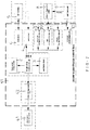
FIG. 4 is a schematic operational block diagram of the present invention. -
FIG. 5 is another schematic operational block diagram ofFIG. 4 . -
FIG. 6 is an operational block diagram of the fuel-saving and energy-saving car controller of the present invention. -
FIG 7 is another schematic operational block diagram ofFIG. 6 . - Referring to the drawings and initially to
FIGS. 1-6 , a fuel-saving and energy-saving car controller in accordance with the preferred embodiment of the present invention is connected with apower supercharger 40 and comprises a powersupercharge control box 51 electrically connected with a direct-currentbrushless motor 41 of thepower supercharger 40. - The
power supercharger 40 has a first end provided with anair inlet pipe 46 connected with anair inlet 21 of anengine 20. Anair cleaner 30 is mounted on a second end of the power supercharger 40 and locked by a retainer "C". The direct-currentbrushless motor 41 is mounted in thepower supercharger 40. The direct-currentbrushless motor 41 of thepower supercharger 40 has arotor 43 provided with a bushing "R", anair inlet fan 44 and two washers "Q". A cone-shaped vortex generator 45 is locked onto a distal end of therotor 43 to evenly distribute and diffuse the air flow in a vortex manner so that the air and the fuel are mixed completely to enhance the burning efficiency. In addition, thevortex generator 45 reduces the noise produced during rotation of theair inlet fan 44. Anair input detector 47 is mounted on theair inlet pipe 46 of thepower supercharger 40. Anair throttle 48 is mounted on theair inlet 21 of theengine 20 and is electrically connected with an accelerator pedal (not shown) to control the air inlet flow into theengine 20. A fuelinjection supply device 49 is mounted on theengine 20 and has a plurality offuel pipes 50 connected withfuel inlets 22 of theengine 20. The fuelinjection supply device 49 is electrically connected with theair input detector 47 and the accelerator pedal. Theair input detector 47 detects the air inlet flow through theair cleaner 30 and the power supercharger 40 into theengine 20 and transmits a signal to the fuelinjection supply device 49 so that the fuelinjection supply device 49 injects a determined amount of fuel. The accelerator pedal is driven by a driver's pedaling force to control the air input of theair throttle 48 and to control the fuel output of the fuelinjection supply device 49. - The power
supercharge control box 51 is electrically connected with acar battery 5. Afuse 52 is mounted between the powersupercharge control box 51 and thecar battery 5 to prevent the direct-currentbrushless motor 41 from being burned or worn out due to an overload. - The power
supercharge control box 51 includes a single-chip control circuit 1, amotor actuating circuit 42 electrically connected between the direct-currentbrushless motor 41 and the single-chip control circuit 1, a liquidcrystal display module 2 electrically connected with the single-chip control circuit 1 to provide a display function, apush button circuit 3 electrically connected with the single-chip control circuit 1 to provide an operation function, a bleeder circuit 4 electrically connected between the single-chip control circuit 1 and thecar battery 5, a buck circuit 6 electrically connected with thecar battery 5, and a communication module communicating between the single-chip control circuit 1 and an on-board diagnostics (OBD) 8. - The
car battery 5 supplies an electric power to the direct-currentbrushless motor 41. The liquidcrystal display module 2 is preferably an organic light emitting diode (OLED). The on-board diagnostics 8 communicates with acar computer 7 by a network. The network is preferably a controller area network (CAN or CAN BUS) which is a communication protocol. The communication module includes a blue tooth communication module 9, aWiFi communication module 10 or an RS232 communication module 11. The RS232 is an interface standard of a serial information communication established by the American electronics industry association (EIA). The powersupercharge control box 51 further includes acommunication unit 12 communicating between the single-chip control circuit 1 and thecar computer 7. Thecommunication unit 12 is preferably a controller area network (CAN or CAN BUS). In practice, thecommunication unit 12 reads the data in thecar computer 7 so as to detect the rotation speed of theengine 20. Then, thecommunication unit 12 transmits a signal to the single-chip control circuit 1 according to the detected rotation speed of theengine 20. Then, the single-chip control circuit 1 drives themotor actuating circuit 42 which controls the direct-current brushless motor 41 to regulate the rotation speed of theair inlet fan 44. - In operation, referring to
FIGS. 4-7 with reference toFIGS. 1-3 , when theengine 20 is started by the driver, the communication module (including the blue tooth communication module 9, theWiFi communication module 10 or the RS232 communication module 11) communicates with the on-board diagnostics 8 which communicates with thecar computer 7 by the controller area network (CAN or CAN BUS), so that the communication module of the powersupercharge control box 51 can read the data in the on-board diagnostics 8 and thecar computer 7 as shown inFIGS. 4 and6 so as to detect the rotation speed of theengine 20. Alternatively, thecommunication unit 12 can directly read the data in thecar computer 7 so as to detect the rotation speed of theengine 20. Then, the communication module transmits a signal to the single-chip control circuit 1 as shown inFIGS. 5 and7 . Then, the single-chip control circuit 1 drives themotor actuating circuit 42 which controls the direct-current brushless motor 41 as shown inFIG. 7 to regulate the rotation speed of theair inlet fan 44. At the same time, theair input detector 47 detects the air inlet flow through theair cleaner 30 and thepower supercharger 40 into theengine 20 and transmits a signal to the fuelinjection supply device 49 so that the fuelinjection supply device 49 injects a determined amount of fuel. - Accordingly, the communication module of the power
supercharge control box 51 reads the data in the on-board diagnostics 8 and thecar computer 7 to detect the rotation speed of theengine 20, so that the fuel-saving and energy-saving car controller of the present invention can properly increase the air input of theengine 20, without increasing the rotation speed of theengine 20, and without increasing the fuel output of the fuelinjection supply device 49, such that the fuel is burned completely, thereby preventing theengine 20 from incurring a carbon deposition, and thereby enhancing the working efficiency of theengine 20. In addition, the car can travel a longer distance at the same amount of fuel, thereby saving the fuel and the energy. - Although the invention has been explained in relation to its preferred embodiment(s) as mentioned above, it is to be understood that many other possible modifications and variations can be made without departing from the scope of the present invention. It is, therefore, contemplated that the appended claim or claims will cover such modifications and variations that fall within the true scope of the invention.
Claims (1)
- A fuel-saving and energy-saving car controller comprising:a power supercharge control box (51) electrically connected with a direct-current brushless motor (41) of a power supercharger (40);wherein:the power supercharger has a first end connected with an engine (20);an air cleaner (30) is mounted on a second end of the power supercharger;the direct-current brushless motor is mounted in the power supercharger and is provided with an air inlet fan (44);an air input detector (47) is mounted on the power supercharger;an air throttle (48) is mounted on the engine and is electrically connected with an accelerator pedal to control an air inlet flow into the engine;a fuel injection supply device (49) is connected with the engine;the fuel injection supply device is electrically connected with the air input detector and the accelerator pedal;the air input detector detects the air inlet flow through the air cleaner and the power supercharger into the engine and transmits a signal to the fuel injection supply device so that the fuel injection supply device injects a determined amount of fuel;the accelerator pedal is driven by a driver's pedaling force to control an air input of the air throttle and to control a fuel output of the fuel injection supply device;the power supercharge control box is electrically connected with a car battery (5);characterized in that:the power supercharge control box includes:a single-chip control circuit (1);a motor actuating circuit (42) electrically connected between the direct-current brushless motor and the single-chip control circuit;a liquid crystal display module (2) electrically connected with the single-chip control circuit;a push button circuit (3) electrically connected with the single-chip control circuit;a bleeder circuit (4) electrically connected between the single-chip control circuit and the car battery;a buck circuit (6) electrically connected with the car battery; anda communication module communicating between the single-chip control circuit and an on-board diagnostics (8);the car battery supplies an electric power to the direct-current brushless motor;the on-board diagnostics communicates with a car computer (7) by a network;the communication module of the power supercharge control box reads data in the on-board diagnostics and the car computer so as to detect a rotation speed of the engine;the communication module transmits a signal to the single-chip control circuit which drives the motor actuating circuit which controls the direct-current brushless motor to regulate a rotation speed of the air inlet fan; andthe air input detector detects the air inlet flow through the air cleaner and the power supercharger into the engine and transmits a signal to the fuel injection supply device so that the fuel injection supply device injects a determined amount of fuel.2. The fuel-saving and energy-saving car controller of claim 1, wherein:the network is a controller area network (CAN or CAN BUS);the communication module includes a blue tooth communication module (9), a WiFi communication module (10) or an RS232 communication module (11);the power supercharge control box further includes a communication unit (12) communicating between the single-chip control circuit and the car computer; andthe communication unit is a controller area network (CAN or CAN BUS).
Priority Applications (3)
| Application Number | Priority Date | Filing Date | Title |
|---|---|---|---|
| PT151983590T PT3179081T (en) | 2015-12-08 | 2015-12-08 | Fuel-saving and energy-saving car controller |
| EP15198359.0A EP3179081B1 (en) | 2015-12-08 | 2015-12-08 | Fuel-saving and energy-saving car controller |
| ES15198359T ES2788670T3 (en) | 2015-12-08 | 2015-12-08 | Fuel Saver and Energy Saver Vehicle Controller |
Applications Claiming Priority (1)
| Application Number | Priority Date | Filing Date | Title |
|---|---|---|---|
| EP15198359.0A EP3179081B1 (en) | 2015-12-08 | 2015-12-08 | Fuel-saving and energy-saving car controller |
Publications (2)
| Publication Number | Publication Date |
|---|---|
| EP3179081A1 true EP3179081A1 (en) | 2017-06-14 |
| EP3179081B1 EP3179081B1 (en) | 2020-04-01 |
Family
ID=54843695
Family Applications (1)
| Application Number | Title | Priority Date | Filing Date |
|---|---|---|---|
| EP15198359.0A Active EP3179081B1 (en) | 2015-12-08 | 2015-12-08 | Fuel-saving and energy-saving car controller |
Country Status (3)
| Country | Link |
|---|---|
| EP (1) | EP3179081B1 (en) |
| ES (1) | ES2788670T3 (en) |
| PT (1) | PT3179081T (en) |
Citations (4)
| Publication number | Priority date | Publication date | Assignee | Title |
|---|---|---|---|---|
| EP0969193A1 (en) * | 1998-06-30 | 2000-01-05 | Tatsumi Corporation | Fuel supply system for automotive engines |
| US20060122762A1 (en) * | 2004-11-15 | 2006-06-08 | Perkins Michael T | On demand boost conditioner (ODBC) |
| WO2008095129A2 (en) * | 2007-01-31 | 2008-08-07 | Turbodyne Technologies, Inc. | Generation and management of mass air flow |
| EP2781717A1 (en) * | 2013-03-18 | 2014-09-24 | Ming-Hung Cheng | Electronic car supercharger with brushless motor |
Family Cites Families (1)
| Publication number | Priority date | Publication date | Assignee | Title |
|---|---|---|---|---|
| JP6272077B2 (en) * | 2014-02-25 | 2018-01-31 | 三菱重工業株式会社 | Turbocharger and ship |
-
2015
- 2015-12-08 ES ES15198359T patent/ES2788670T3/en active Active
- 2015-12-08 PT PT151983590T patent/PT3179081T/en unknown
- 2015-12-08 EP EP15198359.0A patent/EP3179081B1/en active Active
Patent Citations (4)
| Publication number | Priority date | Publication date | Assignee | Title |
|---|---|---|---|---|
| EP0969193A1 (en) * | 1998-06-30 | 2000-01-05 | Tatsumi Corporation | Fuel supply system for automotive engines |
| US20060122762A1 (en) * | 2004-11-15 | 2006-06-08 | Perkins Michael T | On demand boost conditioner (ODBC) |
| WO2008095129A2 (en) * | 2007-01-31 | 2008-08-07 | Turbodyne Technologies, Inc. | Generation and management of mass air flow |
| EP2781717A1 (en) * | 2013-03-18 | 2014-09-24 | Ming-Hung Cheng | Electronic car supercharger with brushless motor |
Also Published As
| Publication number | Publication date |
|---|---|
| ES2788670T3 (en) | 2020-10-22 |
| EP3179081B1 (en) | 2020-04-01 |
| PT3179081T (en) | 2020-04-27 |
Similar Documents
| Publication | Publication Date | Title |
|---|---|---|
| CN102514570B (en) | A kind of series hybrid electric vehicle and driving engine on off control method, system | |
| CN102654082B (en) | The method limiting for the rotating speed of controlling combustion engine | |
| US9555751B1 (en) | Fuel-saving and energy-saving car controller | |
| CN106143468A (en) | For controlling the System and method for the vacuum pump in the gasoline vehicle of clutch | |
| RU2006136794A (en) | HYBRID VEHICLE, HYBRID VEHICLE CONTROL METHOD AND POWER DELIVERY DEVICE | |
| US20150298687A1 (en) | Control apparatus of hybrid vehicle | |
| WO2014132539A1 (en) | Controller for vehicle | |
| CN203098040U (en) | Compound supercharging system of engine | |
| CN102410093B (en) | Realization method and control system for automatically increasing the idle speed of engineering vehicle engine under load | |
| CN201851206U (en) | Optimizing control system of cooling fan | |
| EP3179081B1 (en) | Fuel-saving and energy-saving car controller | |
| US20140261340A1 (en) | Electronic Car Supercharger with Brushless Motor | |
| JP2014218947A (en) | Catalyst warmup control device of vehicle | |
| JP6284087B2 (en) | Automobile fuel saving and energy saving control device | |
| CN102536544A (en) | Engine idle air intake structure and its control method | |
| CN101737150A (en) | Electric centrifugal-type air supplement device | |
| CN205154414U (en) | Hybrid power system intelligent control ware | |
| KR101898189B1 (en) | Apparatus for controlling acceleration using power of starter motor in isg system and method thereof | |
| KR101786697B1 (en) | System of stabilizing combustion and method of stabilizing combustion of hybrid electric vehicle using the same | |
| TW200619060A (en) | Method and device being able to improve the air-fuel ratio of engine | |
| CN202707315U (en) | Low-speed system of double-fuel outboard engine fueller | |
| CN208633934U (en) | Internal combustion engine decarbonization economizer | |
| CN204082401U (en) | Air-strainer | |
| CN105697124A (en) | Cooling adjusting system for automobile engine | |
| TW201408863A (en) | Secondary air supply system and method |
Legal Events
| Date | Code | Title | Description |
|---|---|---|---|
| PUAI | Public reference made under article 153(3) epc to a published international application that has entered the european phase |
Free format text: ORIGINAL CODE: 0009012 |
|
| STAA | Information on the status of an ep patent application or granted ep patent |
Free format text: STATUS: REQUEST FOR EXAMINATION WAS MADE |
|
| 17P | Request for examination filed |
Effective date: 20161207 |
|
| AK | Designated contracting states |
Kind code of ref document: A1 Designated state(s): AL AT BE BG CH CY CZ DE DK EE ES FI FR GB GR HR HU IE IS IT LI LT LU LV MC MK MT NL NO PL PT RO RS SE SI SK SM TR |
|
| AX | Request for extension of the european patent |
Extension state: BA ME |
|
| RAP1 | Party data changed (applicant data changed or rights of an application transferred) |
Owner name: WANG LAI INTERNATIONAL CO., LTD. |
|
| STAA | Information on the status of an ep patent application or granted ep patent |
Free format text: STATUS: EXAMINATION IS IN PROGRESS |
|
| 17Q | First examination report despatched |
Effective date: 20180924 |
|
| RIC1 | Information provided on ipc code assigned before grant |
Ipc: F02D 41/30 20060101ALN20191015BHEP Ipc: F02D 41/28 20060101ALN20191015BHEP Ipc: F02D 41/00 20060101AFI20191015BHEP Ipc: F02B 39/10 20060101ALI20191015BHEP |
|
| GRAP | Despatch of communication of intention to grant a patent |
Free format text: ORIGINAL CODE: EPIDOSNIGR1 |
|
| STAA | Information on the status of an ep patent application or granted ep patent |
Free format text: STATUS: GRANT OF PATENT IS INTENDED |
|
| INTG | Intention to grant announced |
Effective date: 20191125 |
|
| GRAS | Grant fee paid |
Free format text: ORIGINAL CODE: EPIDOSNIGR3 |
|
| GRAA | (expected) grant |
Free format text: ORIGINAL CODE: 0009210 |
|
| STAA | Information on the status of an ep patent application or granted ep patent |
Free format text: STATUS: THE PATENT HAS BEEN GRANTED |
|
| AK | Designated contracting states |
Kind code of ref document: B1 Designated state(s): AL AT BE BG CH CY CZ DE DK EE ES FI FR GB GR HR HU IE IS IT LI LT LU LV MC MK MT NL NO PL PT RO RS SE SI SK SM TR |
|
| REG | Reference to a national code |
Ref country code: GB Ref legal event code: FG4D |
|
| REG | Reference to a national code |
Ref country code: AT Ref legal event code: REF Ref document number: 1251634 Country of ref document: AT Kind code of ref document: T Effective date: 20200415 Ref country code: CH Ref legal event code: EP |
|
| REG | Reference to a national code |
Ref country code: DE Ref legal event code: R096 Ref document number: 602015049750 Country of ref document: DE |
|
| REG | Reference to a national code |
Ref country code: PT Ref legal event code: SC4A Ref document number: 3179081 Country of ref document: PT Date of ref document: 20200427 Kind code of ref document: T Free format text: AVAILABILITY OF NATIONAL TRANSLATION Effective date: 20200417 |
|
| REG | Reference to a national code |
Ref country code: IE Ref legal event code: FG4D |
|
| REG | Reference to a national code |
Ref country code: SE Ref legal event code: TRGR |
|
| REG | Reference to a national code |
Ref country code: NL Ref legal event code: FP |
|
| PG25 | Lapsed in a contracting state [announced via postgrant information from national office to epo] |
Ref country code: BG Free format text: LAPSE BECAUSE OF FAILURE TO SUBMIT A TRANSLATION OF THE DESCRIPTION OR TO PAY THE FEE WITHIN THE PRESCRIBED TIME-LIMIT Effective date: 20200701 |
|
| REG | Reference to a national code |
Ref country code: LT Ref legal event code: MG4D |
|
| REG | Reference to a national code |
Ref country code: ES Ref legal event code: FG2A Ref document number: 2788670 Country of ref document: ES Kind code of ref document: T3 Effective date: 20201022 |
|
| PG25 | Lapsed in a contracting state [announced via postgrant information from national office to epo] |
Ref country code: IS Free format text: LAPSE BECAUSE OF FAILURE TO SUBMIT A TRANSLATION OF THE DESCRIPTION OR TO PAY THE FEE WITHIN THE PRESCRIBED TIME-LIMIT Effective date: 20200801 Ref country code: NO Free format text: LAPSE BECAUSE OF FAILURE TO SUBMIT A TRANSLATION OF THE DESCRIPTION OR TO PAY THE FEE WITHIN THE PRESCRIBED TIME-LIMIT Effective date: 20200701 Ref country code: FI Free format text: LAPSE BECAUSE OF FAILURE TO SUBMIT A TRANSLATION OF THE DESCRIPTION OR TO PAY THE FEE WITHIN THE PRESCRIBED TIME-LIMIT Effective date: 20200401 Ref country code: GR Free format text: LAPSE BECAUSE OF FAILURE TO SUBMIT A TRANSLATION OF THE DESCRIPTION OR TO PAY THE FEE WITHIN THE PRESCRIBED TIME-LIMIT Effective date: 20200702 Ref country code: LT Free format text: LAPSE BECAUSE OF FAILURE TO SUBMIT A TRANSLATION OF THE DESCRIPTION OR TO PAY THE FEE WITHIN THE PRESCRIBED TIME-LIMIT Effective date: 20200401 |
|
| REG | Reference to a national code |
Ref country code: AT Ref legal event code: MK05 Ref document number: 1251634 Country of ref document: AT Kind code of ref document: T Effective date: 20200401 |
|
| PG25 | Lapsed in a contracting state [announced via postgrant information from national office to epo] |
Ref country code: HR Free format text: LAPSE BECAUSE OF FAILURE TO SUBMIT A TRANSLATION OF THE DESCRIPTION OR TO PAY THE FEE WITHIN THE PRESCRIBED TIME-LIMIT Effective date: 20200401 Ref country code: RS Free format text: LAPSE BECAUSE OF FAILURE TO SUBMIT A TRANSLATION OF THE DESCRIPTION OR TO PAY THE FEE WITHIN THE PRESCRIBED TIME-LIMIT Effective date: 20200401 Ref country code: LV Free format text: LAPSE BECAUSE OF FAILURE TO SUBMIT A TRANSLATION OF THE DESCRIPTION OR TO PAY THE FEE WITHIN THE PRESCRIBED TIME-LIMIT Effective date: 20200401 |
|
| PG25 | Lapsed in a contracting state [announced via postgrant information from national office to epo] |
Ref country code: AL Free format text: LAPSE BECAUSE OF FAILURE TO SUBMIT A TRANSLATION OF THE DESCRIPTION OR TO PAY THE FEE WITHIN THE PRESCRIBED TIME-LIMIT Effective date: 20200401 |
|
| REG | Reference to a national code |
Ref country code: DE Ref legal event code: R097 Ref document number: 602015049750 Country of ref document: DE |
|
| PG25 | Lapsed in a contracting state [announced via postgrant information from national office to epo] |
Ref country code: AT Free format text: LAPSE BECAUSE OF FAILURE TO SUBMIT A TRANSLATION OF THE DESCRIPTION OR TO PAY THE FEE WITHIN THE PRESCRIBED TIME-LIMIT Effective date: 20200401 Ref country code: EE Free format text: LAPSE BECAUSE OF FAILURE TO SUBMIT A TRANSLATION OF THE DESCRIPTION OR TO PAY THE FEE WITHIN THE PRESCRIBED TIME-LIMIT Effective date: 20200401 Ref country code: SM Free format text: LAPSE BECAUSE OF FAILURE TO SUBMIT A TRANSLATION OF THE DESCRIPTION OR TO PAY THE FEE WITHIN THE PRESCRIBED TIME-LIMIT Effective date: 20200401 Ref country code: DK Free format text: LAPSE BECAUSE OF FAILURE TO SUBMIT A TRANSLATION OF THE DESCRIPTION OR TO PAY THE FEE WITHIN THE PRESCRIBED TIME-LIMIT Effective date: 20200401 Ref country code: RO Free format text: LAPSE BECAUSE OF FAILURE TO SUBMIT A TRANSLATION OF THE DESCRIPTION OR TO PAY THE FEE WITHIN THE PRESCRIBED TIME-LIMIT Effective date: 20200401 |
|
| PLBE | No opposition filed within time limit |
Free format text: ORIGINAL CODE: 0009261 |
|
| STAA | Information on the status of an ep patent application or granted ep patent |
Free format text: STATUS: NO OPPOSITION FILED WITHIN TIME LIMIT |
|
| PG25 | Lapsed in a contracting state [announced via postgrant information from national office to epo] |
Ref country code: PL Free format text: LAPSE BECAUSE OF FAILURE TO SUBMIT A TRANSLATION OF THE DESCRIPTION OR TO PAY THE FEE WITHIN THE PRESCRIBED TIME-LIMIT Effective date: 20200401 Ref country code: SK Free format text: LAPSE BECAUSE OF FAILURE TO SUBMIT A TRANSLATION OF THE DESCRIPTION OR TO PAY THE FEE WITHIN THE PRESCRIBED TIME-LIMIT Effective date: 20200401 |
|
| 26N | No opposition filed |
Effective date: 20210112 |
|
| PG25 | Lapsed in a contracting state [announced via postgrant information from national office to epo] |
Ref country code: SI Free format text: LAPSE BECAUSE OF FAILURE TO SUBMIT A TRANSLATION OF THE DESCRIPTION OR TO PAY THE FEE WITHIN THE PRESCRIBED TIME-LIMIT Effective date: 20200401 |
|
| PG25 | Lapsed in a contracting state [announced via postgrant information from national office to epo] |
Ref country code: MC Free format text: LAPSE BECAUSE OF FAILURE TO SUBMIT A TRANSLATION OF THE DESCRIPTION OR TO PAY THE FEE WITHIN THE PRESCRIBED TIME-LIMIT Effective date: 20200401 |
|
| REG | Reference to a national code |
Ref country code: BE Ref legal event code: MM Effective date: 20201231 |
|
| PG25 | Lapsed in a contracting state [announced via postgrant information from national office to epo] |
Ref country code: LU Free format text: LAPSE BECAUSE OF NON-PAYMENT OF DUE FEES Effective date: 20201208 Ref country code: IE Free format text: LAPSE BECAUSE OF NON-PAYMENT OF DUE FEES Effective date: 20201208 |
|
| PG25 | Lapsed in a contracting state [announced via postgrant information from national office to epo] |
Ref country code: MT Free format text: LAPSE BECAUSE OF FAILURE TO SUBMIT A TRANSLATION OF THE DESCRIPTION OR TO PAY THE FEE WITHIN THE PRESCRIBED TIME-LIMIT Effective date: 20200401 Ref country code: CY Free format text: LAPSE BECAUSE OF FAILURE TO SUBMIT A TRANSLATION OF THE DESCRIPTION OR TO PAY THE FEE WITHIN THE PRESCRIBED TIME-LIMIT Effective date: 20200401 |
|
| PG25 | Lapsed in a contracting state [announced via postgrant information from national office to epo] |
Ref country code: MK Free format text: LAPSE BECAUSE OF FAILURE TO SUBMIT A TRANSLATION OF THE DESCRIPTION OR TO PAY THE FEE WITHIN THE PRESCRIBED TIME-LIMIT Effective date: 20200401 |
|
| PG25 | Lapsed in a contracting state [announced via postgrant information from national office to epo] |
Ref country code: BE Free format text: LAPSE BECAUSE OF NON-PAYMENT OF DUE FEES Effective date: 20201231 |
|
| PGFP | Annual fee paid to national office [announced via postgrant information from national office to epo] |
Ref country code: GB Payment date: 20231023 Year of fee payment: 9 |
|
| PGFP | Annual fee paid to national office [announced via postgrant information from national office to epo] |
Ref country code: TR Payment date: 20231101 Year of fee payment: 9 Ref country code: SE Payment date: 20231214 Year of fee payment: 9 Ref country code: PT Payment date: 20231110 Year of fee payment: 9 Ref country code: NL Payment date: 20231218 Year of fee payment: 9 Ref country code: IT Payment date: 20231130 Year of fee payment: 9 Ref country code: FR Payment date: 20231211 Year of fee payment: 9 Ref country code: DE Payment date: 20231211 Year of fee payment: 9 Ref country code: CZ Payment date: 20231116 Year of fee payment: 9 |
|
| PGFP | Annual fee paid to national office [announced via postgrant information from national office to epo] |
Ref country code: ES Payment date: 20240206 Year of fee payment: 9 |
|
| PGFP | Annual fee paid to national office [announced via postgrant information from national office to epo] |
Ref country code: CH Payment date: 20240101 Year of fee payment: 9 |
|
| REG | Reference to a national code |
Ref legal event code: R082 Country of ref document: DE Ref country code: DE Ref legal event code: R082 Ref document number: 602015049750 Country of ref document: DE Representative=s name: HEISEL, WOLFGANG, DIPL.-ING., DE |
|
| REG | Reference to a national code |
Ref country code: DE Ref legal event code: R082 Ref document number: 602015049750 Country of ref document: DE Representative=s name: HEISEL, WOLFGANG, DIPL.-ING., DE |
|
| REG | Reference to a national code |
Ref country code: DE Ref legal event code: R119 Ref document number: 602015049750 Country of ref document: DE |
|
| PG25 | Lapsed in a contracting state [announced via postgrant information from national office to epo] |
Ref country code: PT Free format text: LAPSE BECAUSE OF NON-PAYMENT OF DUE FEES Effective date: 20250609 |
|
| PG25 | Lapsed in a contracting state [announced via postgrant information from national office to epo] |
Ref country code: CZ Free format text: LAPSE BECAUSE OF NON-PAYMENT OF DUE FEES Effective date: 20241208 |
|
| REG | Reference to a national code |
Ref country code: SE Ref legal event code: EUG |
|
| REG | Reference to a national code |
Ref country code: CH Ref legal event code: PL |
|
| REG | Reference to a national code |
Ref country code: NL Ref legal event code: MM Effective date: 20250101 |
|
| GBPC | Gb: european patent ceased through non-payment of renewal fee |
Effective date: 20241208 |
|
| PG25 | Lapsed in a contracting state [announced via postgrant information from national office to epo] |
Ref country code: NL Free format text: LAPSE BECAUSE OF NON-PAYMENT OF DUE FEES Effective date: 20250101 |
|
| PG25 | Lapsed in a contracting state [announced via postgrant information from national office to epo] |
Ref country code: DE Free format text: LAPSE BECAUSE OF NON-PAYMENT OF DUE FEES Effective date: 20250701 |
|
| PG25 | Lapsed in a contracting state [announced via postgrant information from national office to epo] |
Ref country code: IT Free format text: LAPSE BECAUSE OF NON-PAYMENT OF DUE FEES Effective date: 20241208 |
|
| PG25 | Lapsed in a contracting state [announced via postgrant information from national office to epo] |
Ref country code: GB Free format text: LAPSE BECAUSE OF NON-PAYMENT OF DUE FEES Effective date: 20241208 |
|
| PG25 | Lapsed in a contracting state [announced via postgrant information from national office to epo] |
Ref country code: FR Free format text: LAPSE BECAUSE OF NON-PAYMENT OF DUE FEES Effective date: 20241231 |
|
| PG25 | Lapsed in a contracting state [announced via postgrant information from national office to epo] |
Ref country code: CH Free format text: LAPSE BECAUSE OF NON-PAYMENT OF DUE FEES Effective date: 20241231 |
|
| REG | Reference to a national code |
Ref country code: ES Ref legal event code: FD2A Effective date: 20260129 |
|
| PG25 | Lapsed in a contracting state [announced via postgrant information from national office to epo] |
Ref country code: ES Free format text: LAPSE BECAUSE OF NON-PAYMENT OF DUE FEES Effective date: 20241209 |
|
| PG25 | Lapsed in a contracting state [announced via postgrant information from national office to epo] |
Ref country code: TR Free format text: LAPSE BECAUSE OF NON-PAYMENT OF DUE FEES Effective date: 20241208 |