EP3179074A1 - Thermal management system - Google Patents
Thermal management system Download PDFInfo
- Publication number
- EP3179074A1 EP3179074A1 EP16201927.7A EP16201927A EP3179074A1 EP 3179074 A1 EP3179074 A1 EP 3179074A1 EP 16201927 A EP16201927 A EP 16201927A EP 3179074 A1 EP3179074 A1 EP 3179074A1
- Authority
- EP
- European Patent Office
- Prior art keywords
- heat
- thermal
- heat exchange
- gas turbine
- management system
- Prior art date
- Legal status (The legal status is an assumption and is not a legal conclusion. Google has not performed a legal analysis and makes no representation as to the accuracy of the status listed.)
- Granted
Links
- 239000012530 fluid Substances 0.000 claims abstract description 127
- 238000004891 communication Methods 0.000 claims abstract description 43
- 238000005461 lubrication Methods 0.000 claims description 26
- 238000001816 cooling Methods 0.000 claims description 12
- 230000010354 integration Effects 0.000 claims description 7
- 238000010348 incorporation Methods 0.000 claims description 5
- 239000007788 liquid Substances 0.000 claims description 5
- 230000007613 environmental effect Effects 0.000 claims description 4
- 239000007789 gas Substances 0.000 description 41
- 239000000446 fuel Substances 0.000 description 21
- 238000011144 upstream manufacturing Methods 0.000 description 16
- 239000000567 combustion gas Substances 0.000 description 7
- 239000003381 stabilizer Substances 0.000 description 6
- 230000006835 compression Effects 0.000 description 4
- 238000007906 compression Methods 0.000 description 4
- 238000010438 heat treatment Methods 0.000 description 4
- 230000008901 benefit Effects 0.000 description 3
- 238000002485 combustion reaction Methods 0.000 description 3
- 230000006870 function Effects 0.000 description 3
- LFQSCWFLJHTTHZ-UHFFFAOYSA-N Ethanol Chemical compound CCO LFQSCWFLJHTTHZ-UHFFFAOYSA-N 0.000 description 2
- 239000000314 lubricant Substances 0.000 description 2
- 239000000463 material Substances 0.000 description 2
- 239000000203 mixture Substances 0.000 description 2
- 230000001141 propulsive effect Effects 0.000 description 2
- 239000002918 waste heat Substances 0.000 description 2
- XLYOFNOQVPJJNP-UHFFFAOYSA-N water Substances O XLYOFNOQVPJJNP-UHFFFAOYSA-N 0.000 description 2
- 241000256259 Noctuidae Species 0.000 description 1
- 238000009825 accumulation Methods 0.000 description 1
- 230000003213 activating effect Effects 0.000 description 1
- 230000009286 beneficial effect Effects 0.000 description 1
- 230000008859 change Effects 0.000 description 1
- 230000007123 defense Effects 0.000 description 1
- 230000001419 dependent effect Effects 0.000 description 1
- 238000010586 diagram Methods 0.000 description 1
- 230000009977 dual effect Effects 0.000 description 1
- 239000000284 extract Substances 0.000 description 1
- 238000000034 method Methods 0.000 description 1
- 230000037361 pathway Effects 0.000 description 1
- 230000002265 prevention Effects 0.000 description 1
- 238000005057 refrigeration Methods 0.000 description 1
Images


Classifications
-
- F—MECHANICAL ENGINEERING; LIGHTING; HEATING; WEAPONS; BLASTING
- F01—MACHINES OR ENGINES IN GENERAL; ENGINE PLANTS IN GENERAL; STEAM ENGINES
- F01D—NON-POSITIVE DISPLACEMENT MACHINES OR ENGINES, e.g. STEAM TURBINES
- F01D25/00—Component parts, details, or accessories, not provided for in, or of interest apart from, other groups
- F01D25/02—De-icing means for engines having icing phenomena
-
- F—MECHANICAL ENGINEERING; LIGHTING; HEATING; WEAPONS; BLASTING
- F02—COMBUSTION ENGINES; HOT-GAS OR COMBUSTION-PRODUCT ENGINE PLANTS
- F02C—GAS-TURBINE PLANTS; AIR INTAKES FOR JET-PROPULSION PLANTS; CONTROLLING FUEL SUPPLY IN AIR-BREATHING JET-PROPULSION PLANTS
- F02C7/00—Features, components parts, details or accessories, not provided for in, or of interest apart form groups F02C1/00 - F02C6/00; Air intakes for jet-propulsion plants
- F02C7/12—Cooling of plants
- F02C7/14—Cooling of plants of fluids in the plant, e.g. lubricant or fuel
-
- B—PERFORMING OPERATIONS; TRANSPORTING
- B64—AIRCRAFT; AVIATION; COSMONAUTICS
- B64D—EQUIPMENT FOR FITTING IN OR TO AIRCRAFT; FLIGHT SUITS; PARACHUTES; ARRANGEMENTS OR MOUNTING OF POWER PLANTS OR PROPULSION TRANSMISSIONS IN AIRCRAFT
- B64D15/00—De-icing or preventing icing on exterior surfaces of aircraft
- B64D15/02—De-icing or preventing icing on exterior surfaces of aircraft by ducted hot gas or liquid
- B64D15/04—Hot gas application
-
- B—PERFORMING OPERATIONS; TRANSPORTING
- B64—AIRCRAFT; AVIATION; COSMONAUTICS
- B64D—EQUIPMENT FOR FITTING IN OR TO AIRCRAFT; FLIGHT SUITS; PARACHUTES; ARRANGEMENTS OR MOUNTING OF POWER PLANTS OR PROPULSION TRANSMISSIONS IN AIRCRAFT
- B64D15/00—De-icing or preventing icing on exterior surfaces of aircraft
- B64D15/02—De-icing or preventing icing on exterior surfaces of aircraft by ducted hot gas or liquid
- B64D15/06—Liquid application
-
- B—PERFORMING OPERATIONS; TRANSPORTING
- B64—AIRCRAFT; AVIATION; COSMONAUTICS
- B64D—EQUIPMENT FOR FITTING IN OR TO AIRCRAFT; FLIGHT SUITS; PARACHUTES; ARRANGEMENTS OR MOUNTING OF POWER PLANTS OR PROPULSION TRANSMISSIONS IN AIRCRAFT
- B64D33/00—Arrangements in aircraft of power plant parts or auxiliaries not otherwise provided for
- B64D33/02—Arrangements in aircraft of power plant parts or auxiliaries not otherwise provided for of combustion air intakes
-
- F—MECHANICAL ENGINEERING; LIGHTING; HEATING; WEAPONS; BLASTING
- F01—MACHINES OR ENGINES IN GENERAL; ENGINE PLANTS IN GENERAL; STEAM ENGINES
- F01D—NON-POSITIVE DISPLACEMENT MACHINES OR ENGINES, e.g. STEAM TURBINES
- F01D11/00—Preventing or minimising internal leakage of working-fluid, e.g. between stages
- F01D11/08—Preventing or minimising internal leakage of working-fluid, e.g. between stages for sealing space between rotor blade tips and stator
- F01D11/14—Adjusting or regulating tip-clearance, i.e. distance between rotor-blade tips and stator casing
- F01D11/20—Actively adjusting tip-clearance
- F01D11/24—Actively adjusting tip-clearance by selectively cooling-heating stator or rotor components
-
- F—MECHANICAL ENGINEERING; LIGHTING; HEATING; WEAPONS; BLASTING
- F01—MACHINES OR ENGINES IN GENERAL; ENGINE PLANTS IN GENERAL; STEAM ENGINES
- F01D—NON-POSITIVE DISPLACEMENT MACHINES OR ENGINES, e.g. STEAM TURBINES
- F01D25/00—Component parts, details, or accessories, not provided for in, or of interest apart from, other groups
- F01D25/08—Cooling; Heating; Heat-insulation
- F01D25/10—Heating, e.g. warming-up before starting
-
- F—MECHANICAL ENGINEERING; LIGHTING; HEATING; WEAPONS; BLASTING
- F02—COMBUSTION ENGINES; HOT-GAS OR COMBUSTION-PRODUCT ENGINE PLANTS
- F02C—GAS-TURBINE PLANTS; AIR INTAKES FOR JET-PROPULSION PLANTS; CONTROLLING FUEL SUPPLY IN AIR-BREATHING JET-PROPULSION PLANTS
- F02C3/00—Gas-turbine plants characterised by the use of combustion products as the working fluid
- F02C3/04—Gas-turbine plants characterised by the use of combustion products as the working fluid having a turbine driving a compressor
-
- F—MECHANICAL ENGINEERING; LIGHTING; HEATING; WEAPONS; BLASTING
- F02—COMBUSTION ENGINES; HOT-GAS OR COMBUSTION-PRODUCT ENGINE PLANTS
- F02C—GAS-TURBINE PLANTS; AIR INTAKES FOR JET-PROPULSION PLANTS; CONTROLLING FUEL SUPPLY IN AIR-BREATHING JET-PROPULSION PLANTS
- F02C7/00—Features, components parts, details or accessories, not provided for in, or of interest apart form groups F02C1/00 - F02C6/00; Air intakes for jet-propulsion plants
- F02C7/04—Air intakes for gas-turbine plants or jet-propulsion plants
- F02C7/047—Heating to prevent icing
-
- F—MECHANICAL ENGINEERING; LIGHTING; HEATING; WEAPONS; BLASTING
- F02—COMBUSTION ENGINES; HOT-GAS OR COMBUSTION-PRODUCT ENGINE PLANTS
- F02C—GAS-TURBINE PLANTS; AIR INTAKES FOR JET-PROPULSION PLANTS; CONTROLLING FUEL SUPPLY IN AIR-BREATHING JET-PROPULSION PLANTS
- F02C7/00—Features, components parts, details or accessories, not provided for in, or of interest apart form groups F02C1/00 - F02C6/00; Air intakes for jet-propulsion plants
- F02C7/06—Arrangements of bearings; Lubricating
-
- B—PERFORMING OPERATIONS; TRANSPORTING
- B64—AIRCRAFT; AVIATION; COSMONAUTICS
- B64D—EQUIPMENT FOR FITTING IN OR TO AIRCRAFT; FLIGHT SUITS; PARACHUTES; ARRANGEMENTS OR MOUNTING OF POWER PLANTS OR PROPULSION TRANSMISSIONS IN AIRCRAFT
- B64D33/00—Arrangements in aircraft of power plant parts or auxiliaries not otherwise provided for
- B64D33/02—Arrangements in aircraft of power plant parts or auxiliaries not otherwise provided for of combustion air intakes
- B64D2033/0233—Arrangements in aircraft of power plant parts or auxiliaries not otherwise provided for of combustion air intakes comprising de-icing means
-
- F—MECHANICAL ENGINEERING; LIGHTING; HEATING; WEAPONS; BLASTING
- F05—INDEXING SCHEMES RELATING TO ENGINES OR PUMPS IN VARIOUS SUBCLASSES OF CLASSES F01-F04
- F05D—INDEXING SCHEME FOR ASPECTS RELATING TO NON-POSITIVE-DISPLACEMENT MACHINES OR ENGINES, GAS-TURBINES OR JET-PROPULSION PLANTS
- F05D2220/00—Application
- F05D2220/30—Application in turbines
- F05D2220/32—Application in turbines in gas turbines
-
- F—MECHANICAL ENGINEERING; LIGHTING; HEATING; WEAPONS; BLASTING
- F05—INDEXING SCHEMES RELATING TO ENGINES OR PUMPS IN VARIOUS SUBCLASSES OF CLASSES F01-F04
- F05D—INDEXING SCHEME FOR ASPECTS RELATING TO NON-POSITIVE-DISPLACEMENT MACHINES OR ENGINES, GAS-TURBINES OR JET-PROPULSION PLANTS
- F05D2260/00—Function
- F05D2260/20—Heat transfer, e.g. cooling
- F05D2260/213—Heat transfer, e.g. cooling by the provision of a heat exchanger within the cooling circuit
-
- F—MECHANICAL ENGINEERING; LIGHTING; HEATING; WEAPONS; BLASTING
- F05—INDEXING SCHEMES RELATING TO ENGINES OR PUMPS IN VARIOUS SUBCLASSES OF CLASSES F01-F04
- F05D—INDEXING SCHEME FOR ASPECTS RELATING TO NON-POSITIVE-DISPLACEMENT MACHINES OR ENGINES, GAS-TURBINES OR JET-PROPULSION PLANTS
- F05D2260/00—Function
- F05D2260/98—Lubrication
-
- Y—GENERAL TAGGING OF NEW TECHNOLOGICAL DEVELOPMENTS; GENERAL TAGGING OF CROSS-SECTIONAL TECHNOLOGIES SPANNING OVER SEVERAL SECTIONS OF THE IPC; TECHNICAL SUBJECTS COVERED BY FORMER USPC CROSS-REFERENCE ART COLLECTIONS [XRACs] AND DIGESTS
- Y02—TECHNOLOGIES OR APPLICATIONS FOR MITIGATION OR ADAPTATION AGAINST CLIMATE CHANGE
- Y02T—CLIMATE CHANGE MITIGATION TECHNOLOGIES RELATED TO TRANSPORTATION
- Y02T50/00—Aeronautics or air transport
- Y02T50/60—Efficient propulsion technologies, e.g. for aircraft
Definitions
- the present subject matter relates generally to a thermal management system having a surface heat exchange module for incorporation into an airplane and/or an engine.
- Gas turbine engines typically include an inlet, a fan, one or more compressors, a combustor, and at least one turbine.
- the compressors compress air which is channeled to the combustor where it is mixed with fuel. The mixture is then ignited for generating hot combustion gases.
- the combustion gases are channeled to the turbine(s) which extracts energy from the combustion gases for powering the compressor(s), as well as for producing useful work to propel an aircraft in flight or to power a load, such as an electrical generator.
- ice may accumulate on exposed engine structures. More specifically, if engines are operated within icing conditions for extended periods of time, ice accumulation within the engine and over exposed engine structures may be significant. Over time, continued operation of the engine, a throttle burst from lower power operations to higher power operations, and/or vibrations due to either turbulence or asymmetry of ice accretion, may cause the accumulated ice build-up to be ingested by the one or more compressors. Such a condition, known as an ice shed, may cause certain problems within the gas turbine engine.
- At least some known engines include a de-icing system.
- Deicing systems typically utilize bleed air from the one or more compressors to provide heat to the desired surfaces.
- Pipes are provided to transport the bleed air to the desired location.
- the pipes can be relatively large making it difficult to package the deicing system, and further the pipes can be relatively heavy, which may detrimentally affecting fuel burn for the engine.
- a deicing system that does not rely on bleed air would be useful. More particularly, a deicing system that does not require pipes for ducting bleed air to one or more surfaces requiring deicing would be particularly beneficial.
- a thermal management system for incorporation at least partially into at least one of a gas turbine engine or an aircraft.
- the thermal management system includes a thermal transport bus having a heat exchange fluid flowing therethrough and a pump for generating a flow of the heat exchange fluid in the thermal transport bus.
- the thermal management system additionally includes one or more heat source exchangers in thermal communication with the heat exchange fluid in the thermal transport bus, and a surface heat exchange module.
- the deicing module is in thermal communication with the heat exchange fluid in the thermal transport bus at a location downstream of the one or more heat source exchangers for transferring heat from the thermal transfer fluid to a surface of one or more components of the gas turbine engine or the aircraft.
- a gas turbine engine in another exemplary embodiment of the present disclosure, includes a compressor section coupled to a turbine section by one or more shafts, and a main lubrication system for providing lubrication to one or more components located in at least one of the compressor section or the turbine section.
- the gas turbine engine also includes a thermal management system.
- the thermal management system includes a thermal transport bus having a heat exchange fluid flowing therethrough, and a pump for generating a flow of the heat exchange fluid in the thermal transport bus.
- the thermal management system also includes one or more heat source exchangers in thermal communication with the heat exchange fluid in the thermal transport bus, the one or more source exchangers including a main lubrication heat exchanger in thermal communication with the main lubrication system.
- the thermal management system also includes a surface heat exchange module in thermal communication with the heat exchange fluid in the thermal transport bus at a location downstream of the one or more heat source exchangers for transferring heat from the thermal transfer fluid to a surface of one or more components of the gas turbine engine.
- FIG. 1 is a schematic, cross-sectional view of a gas turbine engine in accordance with an exemplary embodiment of the present disclosure. More particularly, for the embodiment of FIG. 1 , the gas turbine engine is a high-bypass turbofan jet engine 10, referred to herein as "turbofan engine 10." As shown in FIG. 1 , the turbofan engine 10 defines an axial direction A (extending parallel to a longitudinal centerline 12 provided for reference) and a radial direction R. In general, the turbofan engine 10 includes a fan section 14 and a core turbine engine 16 disposed downstream from the fan section 14.
- the exemplary core turbine engine 16 depicted generally includes a substantially tubular outer casing 18 that defines an annular inlet 20.
- the outer casing 18 encases, in serial flow relationship, a compressor section including a booster or low pressure (LP) compressor 22 and a high pressure (HP) compressor 24; a combustion section 26; a turbine section including a high pressure (HP) turbine 28 and a low pressure (LP) turbine 30; and a jet exhaust nozzle section 32.
- a high pressure (HP) shaft or spool 34 drivingly connects the HP turbine 28 to the HP compressor 24.
- a low pressure (LP) shaft or spool 36 drivingly connects the LP turbine 30 to the LP compressor 22.
- the fan section 14 includes a variable pitch fan 38 having a plurality of fan blades 40 coupled to a disk 42 in a spaced apart manner.
- the fan blades 40 extend outwardly from disk 42 generally along the radial direction R.
- Each fan blade 40 is rotatable relative to the disk 42 about a pitch axis P by virtue of the fan blades 40 being operatively coupled to a suitable actuation member 44 configured to collectively vary the pitch of the fan blades 40 in unison.
- the fan blades 40, disk 42, and actuation member 44 are together rotatable about the longitudinal axis 12 by LP shaft 36 across a power gear box 46.
- the power gear box 46 includes a plurality of gears for stepping down the rotational speed of the LP shaft 36 to a more efficient rotational fan speed.
- the disk 42 is covered by rotatable front hub 48 aerodynamically contoured to promote an airflow through the plurality of fan blades 40.
- the exemplary fan section 14 includes an annular fan casing or outer nacelle 50 that circumferentially surrounds the fan 38 and/or at least a portion of the core turbine engine 16.
- the nacelle 50 is supported relative to the core turbine engine 16 by a plurality of circumferentially-spaced outlet guide vanes 52.
- the nacelle 50 extends over an outer portion of the core turbine engine 16 so as to define a bypass airflow passage 56 therebetween.
- a volume of air 58 enters the turbofan 10 through an associated inlet 60 of the nacelle 50 and/or fan section 14.
- a first portion of the air 58 as indicated by arrows 62 is directed or routed into the bypass airflow passage 56 and a second portion of the air 58 as indicated by arrow 64 is directed or routed into the LP compressor 22.
- the ratio between the first portion of air 62 and the second portion of air 64 is commonly known as a bypass ratio.
- the pressure of the second portion of air 64 is then increased as it is routed through the high pressure (HP) compressor 24 and into the combustion section 26, where it is mixed with fuel and burned to provide combustion gases 66. Subsequently, the combustion gases 66 are routed through the HP turbine 28 and the LP turbine 30, where a portion of thermal and/or kinetic energy from the combustion gases 66 is extracted.
- the combustion gases 66 are then routed through the jet exhaust nozzle section 32 of the core turbine engine 16 to provide propulsive thrust. Simultaneously, the pressure of the first portion of air 62 is substantially increased as the first portion of air 62 is routed through the bypass airflow passage 56 before it is exhausted from a fan nozzle exhaust section 76 of the turbofan 10, also providing propulsive thrust.
- the exemplary turbofan engine 10 further includes various accessory systems to aid in the operation of the turbofan engine 10 and/or an aircraft including the turbofan engine 10 (e.g., FIG. 3 ).
- the exemplary turbofan engine 10 further includes a main lubrication system 78 configured to provide a lubricant to, e.g., various bearings and gear meshes in the compressor section (including the LP compressor 22 and HP compressor 24), the turbine section (including the HP turbine 28 and the LP turbine 30), the HP spool 34, the LP spool 36, and the power gear box 46.
- the lubricant provided by the main lubrication system 78 may increase the useful life of such components and may remove a certain amount of heat from such components.
- the turbofan engine 10 includes a compressor cooling air (CCA) system 80 for providing air from one or both of the HP compressor 24 or LP compressor 22 to one or both of the HP turbine 28 or LP turbine 30.
- the exemplary turbofan engine 10 includes an active thermal clearance control (ACC) system 82 for cooling a casing of the turbine section to maintain a clearance between the various turbine rotor blades and the turbine casing within a desired range throughout various engine operating conditions.
- CCA compressor cooling air
- ACC active thermal clearance control
- the exemplary turbofan engine 10 includes a generator lubrication system 84 for providing lubrication to an electronic generator, as well as cooling/ heat removal for the electronic generator.
- the electronic generator may provide electrical power to, e.g., a startup electric motor for the turbofan engine 10 and/or various other electronic components of the turbofan engine 10 and/or an aircraft including the turbofan engine 10.
- the exemplary turbofan engine 10 drives or enables various other accessory systems, e.g., for an aircraft (such as the aircraft 200 described below with reference to FIG. 3 ) including the exemplary turbofan engine 10.
- the exemplary turbofan engine 10 provides compressed air from the compressor section to an environmental control system (ECS) 86.
- ECS 86 may provide an air supply to a cabin of the aircraft for pressurization and thermal control.
- air may be provided from the exemplary turbofan engine 10 to an electronics cooling system 88 for maintaining a temperature of certain electronic components of the turbofan engine 10 and/or aircraft within a desired range.
- Prior turbofan engines 10 and/or aircrafts included individual heat exchangers for each of these accessory systems to remove heat from air and/or lubrication in such systems.
- aspects of the present disclosure include a thermal management system 100 (see FIG. 2 ) for transferring heat from some or all of such accessory systems to more efficiently remove such heat and/or utilize such heat.
- the exemplary turbofan engine 10 depicted in FIG. 1 is by way of example only, and that in other exemplary embodiments, aspects of the present disclosure may additionally, or alternatively, be applied to any other suitable gas turbine engine.
- the turbofan engine 10 may instead be any other suitable aeronautical gas turbine engine, such as a turbojet engine, turboshaft engine, turboprop engine, etc.
- the exemplary turbofan engine 10 may include or be operably connected to any other suitable accessory systems. Additionally, or alternatively, the exemplary turbofan engine 10 may not include or be operably connected to one or more of the accessory systems discussed above.
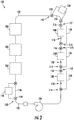
- FIG. 2 a schematic, flow diagram is provided of a thermal management system 100 in accordance with an exemplary embodiment of the present disclosure for incorporation at least partially into the exemplary turbofan engine 10 of FIG. 1 , the exemplary aircraft 200 of FIG. 3 (discussed below), and/or the exemplary aircraft 200 and engine 206 of FIGS. 4 and 5 (discussed below).
- the thermal management system 100 generally includes a thermal transport bus 102.
- the thermal transport bus 102 includes an intermediary heat exchange fluid flowing therethrough and may be formed of one or more suitable fluid conduits.
- the heat exchange fluid may be an incompressible fluid having a high temperature operating range.
- heat exchange fluid may be a water and ethanol mixture, or any suitable dielectric fluid.
- a pump 104 is provided in fluid communication with the heat exchange fluid in the thermal transport bus 102 for generating a flow of the heat exchange fluid in/through the thermal transport bus 102. As viewed in FIG. 2 , the pump 104 may generate a flow of the heat exchange fluid generally in a clockwise direction through the thermal transport bus 102.
- the pump 104 may be a rotary pump including an impeller, or alternatively may be any other suitable fluid pump. Additionally, the pump 104 may be powered by an electric motor, or alternatively may be in mechanical communication with and powered by, e.g., the HP shaft 34 or the LP shaft 36 of the turbofan engine 10. In still other embodiments, the pump 104 may be powered by an auxiliary turbine, which in turn may be powered by bleed air from a compressor section of a gas turbine engine within which the system 100 is incorporated.
- the exemplary thermal management system 100 includes a one or more heat source exchangers 106 in thermal communication with the heat exchange fluid in the thermal transport bus 102.
- the thermal management system 100 depicted includes a plurality of heat source exchangers 106.
- the plurality of heat source exchangers 106 are configured to transfer heat from one or more of the accessory systems of the turbofan engine 10 (or in operable communication with the turbofan engine 10) to the heat exchange fluid in the thermal transport bus 102.
- the plurality of heat source exchangers 106 may include one or more of: a main lubrication system heat exchanger for transferring heat from the main lubrication system 78; a CCA system heat source exchanger for transferring heat from the CCA system 80; an ACC system heat source exchanger for transferring heat from the ACC system 82; a generator lubrication system heat source exchanger for transferring heat from the generator lubrication system 84; an ECS heat exchanger for transferring heat from the ECS 86; an electronics cooling system heat exchanger for transferring heat from the electronics cooling system 88; a vapor compression system heat exchanger; an air cycle system heat exchanger; and an auxiliary system(s) heat source exchanger.
- a main lubrication system heat exchanger for transferring heat from the main lubrication system 78
- a CCA system heat source exchanger for transferring heat from the CCA system 80
- an ACC system heat source exchanger for transferring heat from the ACC system 82
- the auxiliary system(s) heat source exchanger may be configured to transfer heat from one or more of a radar system, a defense system, passenger entertainment systems, etc.
- a thermal management system 100 in accordance with an exemplary embodiment of FIG. 2 may transfer heat from a variety of independent systems to the heat exchange fluid in the thermal transport bus 102 for removal.
- heat source exchangers 106 there are three heat source exchangers 106, the three heat source exchangers 106 each arranged in series flow along the thermal transport bus 102.
- any other suitable number of heat source exchangers 106 may be included and one or more of the heat source exchangers 106 may be arranged in parallel flow along the thermal transport bus 102.
- there may be a single heat source exchanger 106 in thermal communication with the heat exchange fluid in the thermal transport bus or alternatively, there may be at least two heat source exchangers 106, least four heat source exchangers 106, at least five heat source exchangers 106, or at least six heat source exchangers 106 in thermal communication with heat exchange fluid in the thermal transport bus 102.
- the exemplary thermal management system 100 of FIG. 2 further includes one or more heat sink exchanger 108 permanently or selectively in thermal communication with the heat exchange fluid in the thermal transport bus 102.
- the one or more heat sink exchangers 108 are located downstream of the plurality of heat source exchangers 106 and are configured for transferring heat from the heat exchange fluid in the thermal transport bus 102, e.g., to atmosphere, to fuel, to a fan stream, etc.
- the one or more heat sink exchangers 108 may include at least one of a RAM heat exchanger, a fuel heat exchanger, a fan stream heat exchanger, a bleed air heat exchanger, an engine intercooler, or a cold air output of am air cycle system.
- the RAM heat exchanger may be configured as an "air to heat exchange fluid" heat exchanger integrated into one or both of the turbofan engine 10 or an aircraft including the turbofan engine 10. During operation, the RAM heat exchanger may remove heat from any heat exchange fluid therein by flowing a certain amount of RAM air over the RAM heat exchanger.
- the fuel heat exchanger is a "fluid to heat exchange fluid" heat exchanger wherein heat from the heat exchange fluid is transferred to a stream of liquid fuel for the turbofan engine 10.
- the fan stream heat exchanger is generally an "air to heat exchange fluid" heat exchanger which flows, e.g., bypass air over heat exchange fluid to remove heat from the heat exchange fluid.
- the bleed air heat exchanger is generally an "air to heat exchange fluid” heat exchanger which flows, e.g., bleed air from the LP compressor over heat exchange fluid to remove heat from the heat exchange fluid.
- the one or more heat sink exchangers 108 of the thermal management system 100 depicted includes a plurality of individual heat sink exchangers 108. More particularly, for the embodiment of FIG. 2 , the one or more heat sink exchangers 108 include three heat sink exchangers 108 arranged in series. The three heat sink exchangers 108 are configured as a RAM heat exchanger, a fuel heat exchanger, and a fan stream heat exchanger. However, in other exemplary embodiments, the one or more heat sink exchangers 108 may include any other suitable number of heat sink exchangers 108.
- a single heat sink exchanger 108 may be provided, at least two heat sink exchangers 108 may be provided, at least four heat sink exchangers 108 may be provided, or at least five heat sink exchangers 108 may be provided.
- two or more of the one or more heat sink exchangers 108 may alternatively be arranged in parallel flow with one another.
- the plurality of heat sink exchangers 108 are selectively in thermal communication with the heat exchange fluid in the thermal transport bus 102. More particularly, the thermal management system 100 depicted includes a plurality of bypass lines 110 for selectively bypassing each heat sink exchanger 108 in the plurality of heat sink exchangers 108. Each bypass line 110 extends between an upstream juncture 112 and a downstream juncture 114-the upstream juncture 112 located just upstream of a respective heat sink exchanger 108, and the downstream juncture 114 located just downstream of the respective heat sink exchanger 108.
- each bypass line 110 meets at the respective upstream juncture 112 with the thermal transport bus 102 via a three-way heat sink valve 116.
- the three-way heat sink valves 116 each include an inlet fluidly connected with the thermal transport bus 102, a first outlet fluidly connected with the thermal transport bus 102, and a second outlet fluidly connected with the bypass line 110.
- the three-way heat sink valves 116 may each be a variable throughput three-way valve, such that the three-way heat sink valves 116 may vary a throughput from the inlet to the first and/or second outlets.
- the three-way heat sink valves 116 may be configured for providing anywhere between zero percent (0%) and one hundred percent (100%) of the heat exchange fluid from the inlet to the first outlet, and similarly, the three-way heat sink valves 116 may be configured for providing anywhere between zero percent (0%) and one hundred percent (100%) of the heat exchange fluid from the inlet to the second outlet.
- the three-way heat sink valves 116 may be in operable communication with a controller of the turbofan engine 10 and/or of an aircraft including the turbofan engine 10.
- the controller may bypass one or more of the one or more heat sink exchangers 108 based on, e.g., an operating condition of the turbofan engine 10 and/or aircraft, a temperature of the heat exchange fluid, and/or any other suitable variables.
- the controller may bypass one or more of the one or more heat sink exchangers 108 based on a user input.
- each bypass line 110 also meets at the respective downstream juncture 114 with the thermal transport bus 102.
- the thermal transport bus 102 includes a check valve 118 for ensuring a proper flow direction of the heat exchange fluid. More particularly, the check valve 118 prevents a flow of heat exchange fluid from the downstream juncture 114 towards the respective heat sink exchanger 108.
- the thermal management system 100 of FIG. 2 may more efficiently remove heat from the various accessory systems of the turbofan engine 10 and/or the aircraft.
- the various accessory systems may generate a varying amount of heat dependent on various operating conditions of the turbofan engine 10 and/or the aircraft.
- not all of the accessory systems define the same heat pattern (i.e., not all of the accessory systems heat up and cool down at the same time).
- the main lubrication system 78 may require a maximum amount of heat removal during high load conditions of the turbofan engine 10.
- the ECS 86 may require a max amount of heat removal during high-altitude flight. Accordingly, by integrating the heat removal for the variety of different accessory systems, less heat exchangers may be required to remove a desired amount of heat and/or smaller heat exchangers may be required to remove a desired amount of heat.
- heat may be removed from the various accessory systems in a more efficient manner.
- the most efficient heat sink exchanger 108 and/or the surface heat exchange module 136, discussed below
- the additional heat sink exchangers 108 and/or the surface heat exchange module 136, discussed below
- the additional heat sink exchangers 108 (and/or the surface heat exchange module 136, discussed below) have the benefit of adding redundancy to the thermal management system 100.
- the heat exchange fluid may be routed around such failure and the system 100 may continue to provide at least some heat removal.
- the exemplary thermal management system 100 depicted is configured to use a single phase, incompressible thermal transport fluid. It should be appreciated, however, that in other embodiments, the thermal management system 100 may instead use a phase change fluid. With such an embodiment, the thermal management system 100 may include a compressor for compressing the heat exchange fluid in the thermal transport bus 102, and an expansion device for expanding the heat exchange fluid in the thermal transport bus 102. The compressor may be selectively in fluid communication with the heat exchange fluid at a location downstream of the heat source exchangers 106 and upstream of the one or more heat sink exchangers 108.
- the expansion device may be selectively in fluid communication with the heat exchange fluid at a location downstream of the one or more heat sink exchangers 108 and upstream of the heat source exchangers 106.
- the compressor may be driven by, e.g., an electric motor, or alternatively may be in mechanical communication with and driven by a rotary component of the turbofan engine 10, such as the HP shaft 34 or the LP shaft 36.
- the one or more heat sink exchangers 108 (and/or the deicing module 136, discussed below) would act as a condenser, and the plurality of heat source exchangers 106 would act as an evaporator.
- the expansion device may be utilized as a power generating device configured to generate rotational power from a flow of heat exchange fluid therethrough.
- the thermal transport bus 102 additionally includes a compressor bypass line 124 for selectively bypassing the compressor 120 and an expansion device bypass line 126 for selectively bypassing the expansion device 122.
- a three-way compressor bypass valve 128 is positioned at an upstream juncture 130 for selectively bypassing the compressor 120
- a three-way expansion device bypass valve 132 is positioned at an upstream juncture 134 for selectively bypassing the expansion device 122.
- the three-way compressor bypass valve 128 and three-way expansion device bypass valve 132 may each be configured in substantially the same manner as the exemplary three-way heat sink valves 116 described above for bypassing operation of a respective heat sink exchanger 108.
- the exemplary thermal management system 100 of FIG. 2 additionally includes a fuel chiller 144 selectively in thermal communication with heat exchange fluid in the thermal transport bus 102 at a location upstream of the plurality of heat source exchangers 106 and downstream of the one or more heat sink exchangers 108.
- the fuel chiller 144 may be configured to remove heat from the fuel of the turbofan engine 10 to assist with maintaining the fuel within a desired temperature range.
- the thermal management system 100 additionally includes a fuel chiller bypass line 146 for selectively bypassing the fuel chiller 144 and a three-way fuel chiller bypass valve 148.
- the three-way fuel chiller bypass valve 148 is located at an upstream juncture 150 and fluidly connects the thermal transport bus 102 and fuel chiller bypass line 146.
- the fuel chiller bypass valve 148 may be a variable throughput three-way valve configured in substantially the same manner as the exemplary three-way heat sink valves 116 described above for bypassing operation of a respective heat sink exchanger 108.
- the exemplary thermal management system 100 of FIG. 2 includes features for heating or de-icing certain components of an aircraft and/or the turbofan engine 10.
- the exemplary thermal management system 100 includes a surface heat exchange 136 in thermal communication with the heat exchange fluid in the thermal transport bus 102 at a location downstream from the one or more heat source exchangers 106 for transferring heat from the thermal transfer fluid to a surface of one or more components of the turbofan engine 10 or an aircraft (e.g., aircraft 200 of FIGS. 3 and/or 4).
- the surface heat exchange module 136 is also located upstream of the one or more heat sink exchangers 108.
- the surface heat exchange module 136 may instead be located at any suitable location downstream of the one or more heat source exchangers 106.
- the surface heat exchange module 136 may be located upstream of the pump 120, or alternatively may be located downstream of one or more of the heat sink exchangers 108.
- the thermal management system 100 additionally includes a bypass line 138 for selectively bypassing the surface heat exchange module 136.
- a three-way surface heat exchange module valve 140 is positioned at an upstream juncture 142 for selectively activating the surface heat exchange module 136.
- the three-way surface heat exchange module valve 140 may be configured in substantially the same manner as the exemplary three-way heat sink valves 116 described above for bypassing operation of a respective heat sink exchanger 108.
- the surface heat exchange module 136 may be configured as a de-icing module including one or more heat exchangers for integration into a surface of one or more components of the turbofan engine 10 and/or aircraft.
- inclusion of a surface heat exchange/ deicing module with a thermal management system may serve a dual function of deicing or heating certain components of an aircraft and/or turbofan engine, as well as removing heat from a heat exchange fluid flowing through a thermal transport bus of the thermal management system. Accordingly, such a configuration may provide for a more efficient system for deicing certain components of the turbofan engine and/or aircraft by utilizing waste heat removed from one or more other components/systems of the aircraft and/or engine.
- the thermal management system 100 is provided by way of example only and that in other exemplary embodiments the thermal management system 100 may be configured in any other suitable manner.
- the thermal management system 100 may not operate on a refrigeration cycle, i.e., the thermal management system 100 may not include one or both of the compressor 120 or the expansion device 122.
- the thermal management system 100 may not include certain other components depicted in FIG. 2 , such as the fuel chiller 144.
- the thermal management system 100 may be configured as a dedicated surface heat exchange thermal management system.
- the thermal management system may not include one or more heat sink exchangers 108 in thermal communication with the heat exchange fluid in the thermal transport bus 102, and instead, the surface heat exchange module 136 may be configured as the primary means for removing heat from the heat exchange fluid in the thermal transport bus 102.
- the one or more heat source exchangers 106 may include, a vapor compression system (i.e., a condenser portion of the vapor compression system) and a heat exchanger from an air cycle system (configured to receive air from the turbofan engine and cool such air to be provided to the aircraft).
- a vapor compression system i.e., a condenser portion of the vapor compression system
- an air cycle system configured to receive air from the turbofan engine and cool such air to be provided to the aircraft.
- the thermal transport bus 100 may include the surface heat exchange module 136. A portion of the heat from the thermal transport fluid may be transferred through the surface heat exchange module 136.
- the thermal transport bus 100 may then include a plurality of heat sink exchangers 108, such as an engine intercooler, a RAM air heat exchanger, and a cold air output of the air cycle system.
- the thermal transport bus 100 may additionally include a heat sink exchanger 108 located between two of the heat source exchangers 106 (e.g., a fuel system heat exchanger located between the condenser portion of the vapor compression system and the heat exchanger from the air cycle system).
- FIG. 3 a thermal management system 100 in accordance with another exemplary embodiment of the present disclosure is provided.
- the exemplary thermal management system 100 depicted schematically in FIG. 3 may be configured in substantially the same manner as the exemplary thermal management system 100 described above with reference to FIG. 2 .
- Like numerals have been used in FIG. 3 to identify the same or similar components as the thermal management system 100 of FIG. 2 .
- the thermal management system 100 is incorporated into an aircraft 200 and at least partially into a gas turbine engine.
- the exemplary aircraft 200 depicted in FIG. 3 generally defines a longitudinal centerline 202 that extends therethrough, a lateral direction L, a forward end 204, and an aft end 206.
- the aircraft 200 includes a fuselage 208, extending longitudinally from the forward end 202 of the aircraft 200 to the aft end 204 of the aircraft 200, and a pair of wings 210.
- a first of such wings 210 extends laterally outwardly with respect to the longitudinal centerline 14 from a port side 212 of the fuselage 208 and a second of such wings 210 extends laterally outwardly with respect to the longitudinal centerline 14 from a starboard side 214 of the fuselage 208.
- Each of the wings 210 for the exemplary embodiment depicted includes a leading edge 216 and a trailing edge 218.
- the aircraft 200 further includes a vertical stabilizer 220 having a rudder flap for yaw control, and a pair of horizontal stabilizers 222, each having an elevator flap for pitch control.
- the fuselage 208 additionally includes an outer surface 224. It should be appreciated however, that in other exemplary embodiments of the present disclosure, the aircraft 200 may additionally or alternatively include any other suitable configuration of stabilizer that may or may not extend directly along a vertical direction or the lateral direction L.
- the exemplary aircraft 200 of FIG. 3 further includes a pair of aircraft engines, at least one of which mounted to each of the pair of wings 210.
- the aircraft engines are configured as a first turbofan jet engine 226 and a second turbofan jet engine 228, each suspended beneath the wings 210 in an underwing configuration.
- the thermal management system 100 of FIG. 3 is integrated into the exemplary aircraft 200 and/or one or more of the turbofan engines 226, 228.
- the exemplary thermal management system 100 includes a thermal transport bus 102 having a heat exchange fluid flowing therethrough, along with a pump 104 for generating a flow of the heat exchange fluid in the thermal transport bus 102.
- the exemplary thermal management system 100 includes one or more heat source exchangers 106 and one or more heat sink exchangers 108.
- the one or more heat source exchangers 106 are in thermal communication with the heat exchange fluid in the thermal transport bus 102 and the one or more heat sink exchangers 108 are permanently or selectively in thermal communication with the heat exchange fluid in a thermal transport bus 102.
- the one or more heat sink exchangers 108 are positioned at a location downstream of the one or more heat source exchangers 106 along the thermal transport bus 102. It should be appreciated that the thermal management system 100 of FIG. 3 is depicted schematically, and that the one or more heat source exchangers 106 in/or one or more heat sink exchangers 108 may be installed at any location within the aircraft 200 and/or the turbofan engines 226, 228. For example, in the exemplary embodiment of FIG. 3 , one or more of the heat source exchangers 106 may be located in the turbofan engine 226 and one or more of the heat source exchangers 106 may be located elsewhere within the aircraft 200. Similarly, one or more of the heat sink exchangers 108 may be located in the turbofan engine 226 and one or more of the heat sink exchangers 108 may be located elsewhere within the aircraft 200.
- the thermal management system 100 includes a surface heat exchange module 136 including one or more heat exchangers 238 (depicted in phantom) for providing heat to certain components of the aircraft 200 and/or turbofan engines 226, 228.
- the surface heat exchange module 136 may be configured for deicing certain surfaces of the aircraft 200 or simply heating certain surfaces of the aircraft 200.
- FIG. 4 provides a perspective view of a port side 212 of an aircraft 200 having the exemplary surface heat exchange module 136 of the thermal management system 100 incorporated therein
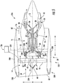
- FIG. 5 provides a side, schematic view of a turbofan engine 226 of the exemplary aircraft 200 of FIG. 4 having the exemplary surface heat exchange module 136 of the thermal management system 100 incorporated therein.
- the exemplary surface heat exchange module 136 depicted is incorporated into a thermal management system 100, such as the thermal management system 100 described above with reference to FIG. 2 and/or FIG. 3 .
- the exemplary aircraft 200 of FIG. 4 may be configured in substantially the same manner as the exemplary aircraft 200 described above with reference to FIG. 3 .
- the aircraft 200 generally includes a fuselage 208 and a pair of wings 210.
- a first of the pair of wings 210 extends laterally outward from a starboard side 214 of the aircraft 200 (not shown) and a second of the pair of wings 210 extends laterally outward from an opposite port side 212 of the aircraft 200.
- the aircraft 200 may include one or more aircraft engines mounted beneath each of the pair of wings 210.
- the aircraft 200 includes the turbofan engine 226 mounted beneath the wing 210 extending outwardly from the port side 212 of the aircraft 200.
- the exemplary turbofan engine 226 generally defines an axial direction A (extending parallel to a longitudinal centerline 12 provided for reference), a radial direction R, and a circumferential direction (not shown).
- the turbofan engine 226 depicted in FIG. 5 may be configured in substantially the same manner as the exemplary turbofan engine 10 described above with reference to FIG. 1 . Accordingly, the same or similar numbering may refer to same or similar components.
- the exemplary turbofan engine 226 generally includes a fan section 14 and a core turbine engine 16 disposed downstream from the fan section 14.
- the exemplary core turbine engine 16 depicted generally includes a substantially tubular outer casing 18 that defines an annular inlet 20.
- the outer casing 18 encases, in serial flow relationship, a compressor section; a combustion section 26; a turbine section; and a jet exhaust nozzle section 32.
- a pair of shafts 34, 36 drivingly connects the compressor section to the turbine section.
- the fan section 14 includes a fan 38 having a plurality of fan blades 40 coupled to a rotor disk 42 in a spaced apart manner.
- the disk 42 is covered by rotatable front hub 48 aerodynamically contoured to promote an airflow through the plurality of fan blades 40.
- the exemplary fan section 14 includes an annular fan casing or outer nacelle 50 that circumferentially surrounds the fan 38 and/or at least a portion of the core turbine engine 16.
- the outer nacelle 50 may generally include a nose cowl 230 positioned at a forward end of the nacelle 50 defining an inlet 60 to the turbofan engine 226, and a fan cowl 232 positioned aft of the nose cowl 230 and extending around/ enclosing the fan 38.
- a volume of air 58 enters the turbofan 10 through the inlet 60 of the nacelle 50 and/or fan section 14.
- a first portion of the air 58 as indicated by arrows 62 is directed or routed into the bypass airflow passage 56 and a second portion of the air 58 as indicated by arrow 64 is directed or routed into a core air flowpath 37.
- the volume of air 58 is separated into the first and second portions of air 62, 64 by a splitter 234 extending around the inlet 20 to the core air flowpath 37.
- one or more inlet guide vanes 236 are positioned at a forward end of the core air flowpath 37, proximate the inlet 20, to direct the second flow of air 64 in a desired manner through the core air flowpath 37.
- the exemplary surface heat exchange module 136 depicted is incorporated into a thermal management system 100 in accordance with an exemplary embodiment present disclosure. Accordingly, the exemplary surface heat exchange module 136 may be in thermal communication with a heat exchange fluid in a thermal transport bus 102 at a location downstream of one or more heat source exchangers 106 of the thermal management system 100. The surface heat exchange module 136 may thus be configured for transferring heat from the thermal transfer fluid to a surface of one or more components of the turbofan engine 226 for the aircraft 200.
- the exemplary surface heat exchange module 136 includes a plurality of heat exchangers 238 for integration into the surface of the one or more components of the aircraft 200, connected via a plurality of conduits 239.
- the exemplary surface heat exchange module 136 depicted includes a plurality of heat exchangers 238 integrated into an outside surface 240 of the wing 210 of the aircraft 200 and an outside surface 224 of a fuselage 208 of the aircraft 200.
- the exemplary surface heat exchange module 136 depicted includes one or more heat exchangers 238 integrated into the surface 240 of the wing 210 at the leading edge 216 of the wing 210 on the port side 212 of the aircraft 200, the surface 240 of the wing 210 at the trailing edge 218 of the wing 210 on the port side 212 of the aircraft 200, and the surface 224 of the fuselage 208 of the aircraft 200.
- the exemplary surface heat exchange module 136 may include one or more heat exchangers 238 integrated into a surface of any other component of the aircraft 200, such as a nose cone of the aircraft 200 (at the forward end 204 of the aircraft 200), or one or more stabilizers (such as the vertical stabilizer 220 or the horizontal stabilizer 222) of the aircraft 200.
- the surface heat exchange module 136 may not include one or more of the heat exchangers 238 depicted in FIG. 4 .
- the exemplary surface heat exchange module 136 includes a plurality of heat exchangers 238 for integration into a surface of one or more components of the exemplary turbofan engine 226.
- the exemplary surface heat exchange module 136 includes a plurality of heat exchangers 238 integrated into a surface of the nose cowl 230 of the turbofan engine 226, the fan cowl 232 of the turbofan engine 226, at least one of the inlet guide vanes 236 of the turbofan engine 226, the splitter 234 of the turbofan engine 226, and the rotatable front hub 48 of the turbofan engine 226.
- the surface heat exchange module 136 may include one or more heat exchangers 238 integrated into any other suitable surface of the turbofan engine 226, or alternatively, the surface heat exchange module 136 may not include one or more of the plurality of heat exchangers 238 depicted in FIGS. 4 and 5 .
- the plurality of heat exchangers 238 integrated into the surfaces of the various components of the turbofan engine 226 and/or the aircraft 200 may be configured for removing an amount of ice or preventing an amount of ice from forming on the respective surfaces.
- the surface heat exchange module 136 may be configured as a de-icing module.
- the surface heat exchange module 136 may additionally include one or more heat exchangers integrated into various other surfaces for heating such surfaces regardless of whether or not icing is a concern.
- the surface heat exchange module 136 may include one or more heat exchangers configured as surface heat exchangers for, e.g., one or more outlet guide vanes, fan ducts, etc.
- the plurality of heat exchangers 238 integrated into the surfaces of the various components of the turbofan engine 226 and/or the aircraft 200 may be configured in any suitable manner for transferring heat from a heat exchange fluid to such surface.
- one or more of the plurality of heat exchangers 238 may include a conduit extending adjacent to an outside surface of the component to be de-iced, such that an amount of heat from a heat exchange fluid flowing therethrough transfers to such surface.
- one or more of the plurality of heat exchangers 238 may include an intermediate material configured to transfer heat from a fluid to the surface of the component to be de-iced.
- one or more of the plurality of heat exchangers 238 may be integrated into the material forming the surface of the component to be de-iced.
- the surface heat exchange module 136 may be configured as a closed loop module configured to transfer heat from a thermal transfer fluid (flowing through the thermal transfer bus 102 of the thermal management system 100) to a separate surface heat exchange module fluid.
- the deicing module fluid may then be flowed through the heat exchangers 238, connected via conduits 239, to provide heat to the desired surfaces of the various components of the aircraft 200 and/or gas turbine engine.
- the surface heat exchange module 136 may be configured to receive a flow of the thermal transfer fluid (flowing through the thermal transfer bus 102 of the thermal management system 100), and flow such thermal transfer fluid to the various heat exchangers 238 configured to provide an amount of heat to the surfaces of the various components of the aircraft 200 and/or gas turbine engine.
- the plurality of conduits 239 may be configured as part of the thermal transport bus 102 of the thermal management system 100.
- a gas turbine engine and/or aircraft including a thermal management system having a surface heat exchange module in accordance with an exemplary embodiment of the present disclosure may more efficiently perform ice prevention/removal functions. More particularly, utilizing a liquid to de-ice various components of the aircraft and/or gas turbine engine may more efficiently provide heat to such components (as compared to utilizing a bleed air). Further, utilizing heat from a thermal management systems in accordance with an exemplary embodiment of the present disclosure may add to an overall efficiency of the gas turbine engine and/or aircraft by utilizing waste heat to perform a function that may otherwise require an additional expenditure of energy.
- one or more of aircraft engines may have a dedicated thermal transport system and the aircraft into which the one or more of aircraft engines are installed may also have a dedicated thermal transport system.
- the thermal transport systems may include a common heat exchanger through which the two systems may interface and exchange heat. Accordingly, which such an exemplary embodiment, the engine thermal transport system may offload an amount of heat to aircraft thermal transport system and vice versa.
Abstract
Description
- The present subject matter relates generally to a thermal management system having a surface heat exchange module for incorporation into an airplane and/or an engine.
- Gas turbine engines typically include an inlet, a fan, one or more compressors, a combustor, and at least one turbine. The compressors compress air which is channeled to the combustor where it is mixed with fuel. The mixture is then ignited for generating hot combustion gases. The combustion gases are channeled to the turbine(s) which extracts energy from the combustion gases for powering the compressor(s), as well as for producing useful work to propel an aircraft in flight or to power a load, such as an electrical generator.
- When the engines operate in icing conditions, e.g., exposed to clouds of super-cooled water droplets, ice may accumulate on exposed engine structures. More specifically, if engines are operated within icing conditions for extended periods of time, ice accumulation within the engine and over exposed engine structures may be significant. Over time, continued operation of the engine, a throttle burst from lower power operations to higher power operations, and/or vibrations due to either turbulence or asymmetry of ice accretion, may cause the accumulated ice build-up to be ingested by the one or more compressors. Such a condition, known as an ice shed, may cause certain problems within the gas turbine engine.
- To facilitate preventing ice accretion within the engine and over exposed surfaces adjacent the engine, at least some known engines include a de-icing system. Deicing systems typically utilize bleed air from the one or more compressors to provide heat to the desired surfaces. Pipes are provided to transport the bleed air to the desired location. However, the pipes can be relatively large making it difficult to package the deicing system, and further the pipes can be relatively heavy, which may detrimentally affecting fuel burn for the engine.
- Accordingly, a deicing system that does not rely on bleed air would be useful. More particularly, a deicing system that does not require pipes for ducting bleed air to one or more surfaces requiring deicing would be particularly beneficial.
- Aspects and advantages of the invention will be set forth in part in the following description, or may be obvious from the description, or may be learned through practice of the invention.
- In one exemplary embodiment of the present disclosure a thermal management system for incorporation at least partially into at least one of a gas turbine engine or an aircraft is provided. The thermal management system includes a thermal transport bus having a heat exchange fluid flowing therethrough and a pump for generating a flow of the heat exchange fluid in the thermal transport bus. The thermal management system additionally includes one or more heat source exchangers in thermal communication with the heat exchange fluid in the thermal transport bus, and a surface heat exchange module. The deicing module is in thermal communication with the heat exchange fluid in the thermal transport bus at a location downstream of the one or more heat source exchangers for transferring heat from the thermal transfer fluid to a surface of one or more components of the gas turbine engine or the aircraft.
- In another exemplary embodiment of the present disclosure, a gas turbine engine is provided. The gas turbine engine includes a compressor section coupled to a turbine section by one or more shafts, and a main lubrication system for providing lubrication to one or more components located in at least one of the compressor section or the turbine section. The gas turbine engine also includes a thermal management system. The thermal management system includes a thermal transport bus having a heat exchange fluid flowing therethrough, and a pump for generating a flow of the heat exchange fluid in the thermal transport bus. The thermal management system also includes one or more heat source exchangers in thermal communication with the heat exchange fluid in the thermal transport bus, the one or more source exchangers including a main lubrication heat exchanger in thermal communication with the main lubrication system. The thermal management system also includes a surface heat exchange module in thermal communication with the heat exchange fluid in the thermal transport bus at a location downstream of the one or more heat source exchangers for transferring heat from the thermal transfer fluid to a surface of one or more components of the gas turbine engine.
- These and other features, aspects and advantages of the present invention will become better understood with reference to the following description and appended claims. The accompanying drawings, which are incorporated in and constitute a part of this specification, illustrate embodiments of the invention and, together with the description, serve to explain the principles of the invention.
- A full and enabling disclosure of the present invention, including the best mode thereof, directed to one of ordinary skill in the art, is set forth in the specification, which makes reference to the appended figures, in which:
-
FIG. 1 is a schematic, cross-sectional view of an exemplary gas turbine engine according to various embodiments of the present subject matter. -
FIG. 2 is a simplified schematic view of a thermal management system in accordance with an exemplary embodiment of the present disclosure. -
FIG. 3 is a simplified schematic view of a thermal management system in accordance with another exemplary embodiment of the present disclosure. -
FIG. 4 is a surface heat exchange module of a thermal management system in accordance with an exemplary embodiment of a present disclosure. -
FIG. 5 is a surface heat exchange module of a thermal management system in accordance with another exemplary embodiment of the present disclosure. - Reference will now be made in detail to present embodiments of the invention, one or more examples of which are illustrated in the accompanying drawings. The detailed description uses numerical and letter designations to refer to features in the drawings. Like or similar designations in the drawings and description have been used to refer to like or similar parts of the invention. As used herein, the terms "first", "second", and "third" may be used interchangeably to distinguish one component from another and are not intended to signify location or importance of the individual components. The terms "upstream" and "downstream" refer to the relative direction with respect to fluid flow in a fluid pathway. For example, "upstream" refers to the direction from which the fluid flows, and "downstream" refers to the direction to which the fluid flows.
- Referring now to the drawings, wherein identical numerals indicate the same elements throughout the figures,
FIG. 1 is a schematic, cross-sectional view of a gas turbine engine in accordance with an exemplary embodiment of the present disclosure. More particularly, for the embodiment ofFIG. 1 , the gas turbine engine is a high-bypassturbofan jet engine 10, referred to herein as "turbofan engine 10." As shown inFIG. 1 , theturbofan engine 10 defines an axial direction A (extending parallel to alongitudinal centerline 12 provided for reference) and a radial direction R. In general, theturbofan engine 10 includes afan section 14 and acore turbine engine 16 disposed downstream from thefan section 14. - The exemplary
core turbine engine 16 depicted generally includes a substantially tubularouter casing 18 that defines anannular inlet 20. Theouter casing 18 encases, in serial flow relationship, a compressor section including a booster or low pressure (LP)compressor 22 and a high pressure (HP)compressor 24; acombustion section 26; a turbine section including a high pressure (HP)turbine 28 and a low pressure (LP)turbine 30; and a jetexhaust nozzle section 32. A high pressure (HP) shaft orspool 34 drivingly connects the HPturbine 28 to the HPcompressor 24. A low pressure (LP) shaft orspool 36 drivingly connects theLP turbine 30 to theLP compressor 22. - For the embodiment depicted, the
fan section 14 includes avariable pitch fan 38 having a plurality offan blades 40 coupled to adisk 42 in a spaced apart manner. As depicted, thefan blades 40 extend outwardly fromdisk 42 generally along the radial direction R. Eachfan blade 40 is rotatable relative to thedisk 42 about a pitch axis P by virtue of thefan blades 40 being operatively coupled to asuitable actuation member 44 configured to collectively vary the pitch of thefan blades 40 in unison. Thefan blades 40,disk 42, andactuation member 44 are together rotatable about thelongitudinal axis 12 byLP shaft 36 across apower gear box 46. Thepower gear box 46 includes a plurality of gears for stepping down the rotational speed of theLP shaft 36 to a more efficient rotational fan speed. - Referring still to the exemplary embodiment of
FIG. 1 , thedisk 42 is covered by rotatablefront hub 48 aerodynamically contoured to promote an airflow through the plurality offan blades 40. Additionally, theexemplary fan section 14 includes an annular fan casing orouter nacelle 50 that circumferentially surrounds thefan 38 and/or at least a portion of thecore turbine engine 16. Thenacelle 50 is supported relative to thecore turbine engine 16 by a plurality of circumferentially-spacedoutlet guide vanes 52. Moreover, thenacelle 50 extends over an outer portion of thecore turbine engine 16 so as to define abypass airflow passage 56 therebetween. - During operation of the
turbofan engine 10, a volume ofair 58 enters theturbofan 10 through an associatedinlet 60 of thenacelle 50 and/orfan section 14. As the volume ofair 58 passes across thefan blades 40, a first portion of theair 58 as indicated byarrows 62 is directed or routed into thebypass airflow passage 56 and a second portion of theair 58 as indicated byarrow 64 is directed or routed into theLP compressor 22. The ratio between the first portion ofair 62 and the second portion ofair 64 is commonly known as a bypass ratio. The pressure of the second portion ofair 64 is then increased as it is routed through the high pressure (HP)compressor 24 and into thecombustion section 26, where it is mixed with fuel and burned to providecombustion gases 66. Subsequently, thecombustion gases 66 are routed through the HPturbine 28 and theLP turbine 30, where a portion of thermal and/or kinetic energy from thecombustion gases 66 is extracted. - The
combustion gases 66 are then routed through the jetexhaust nozzle section 32 of thecore turbine engine 16 to provide propulsive thrust. Simultaneously, the pressure of the first portion ofair 62 is substantially increased as the first portion ofair 62 is routed through thebypass airflow passage 56 before it is exhausted from a fannozzle exhaust section 76 of theturbofan 10, also providing propulsive thrust. - Moreover, as is depicted schematically, the
exemplary turbofan engine 10 further includes various accessory systems to aid in the operation of theturbofan engine 10 and/or an aircraft including the turbofan engine 10 (e.g.,FIG. 3 ). For example, theexemplary turbofan engine 10 further includes amain lubrication system 78 configured to provide a lubricant to, e.g., various bearings and gear meshes in the compressor section (including theLP compressor 22 and HP compressor 24), the turbine section (including theHP turbine 28 and the LP turbine 30), theHP spool 34, theLP spool 36, and thepower gear box 46. The lubricant provided by themain lubrication system 78 may increase the useful life of such components and may remove a certain amount of heat from such components. Additionally, theturbofan engine 10 includes a compressor cooling air (CCA)system 80 for providing air from one or both of theHP compressor 24 orLP compressor 22 to one or both of theHP turbine 28 orLP turbine 30. Moreover, theexemplary turbofan engine 10 includes an active thermal clearance control (ACC)system 82 for cooling a casing of the turbine section to maintain a clearance between the various turbine rotor blades and the turbine casing within a desired range throughout various engine operating conditions. Furthermore, theexemplary turbofan engine 10 includes agenerator lubrication system 84 for providing lubrication to an electronic generator, as well as cooling/ heat removal for the electronic generator. The electronic generator may provide electrical power to, e.g., a startup electric motor for theturbofan engine 10 and/or various other electronic components of theturbofan engine 10 and/or an aircraft including theturbofan engine 10. - As is also depicted schematically, the
exemplary turbofan engine 10 drives or enables various other accessory systems, e.g., for an aircraft (such as theaircraft 200 described below with reference toFIG. 3 ) including theexemplary turbofan engine 10. For example, theexemplary turbofan engine 10 provides compressed air from the compressor section to an environmental control system (ECS) 86. TheECS 86 may provide an air supply to a cabin of the aircraft for pressurization and thermal control. Additionally, air may be provided from theexemplary turbofan engine 10 to anelectronics cooling system 88 for maintaining a temperature of certain electronic components of theturbofan engine 10 and/or aircraft within a desired range. -
Prior turbofan engines 10 and/or aircrafts included individual heat exchangers for each of these accessory systems to remove heat from air and/or lubrication in such systems. However, aspects of the present disclosure include a thermal management system 100 (seeFIG. 2 ) for transferring heat from some or all of such accessory systems to more efficiently remove such heat and/or utilize such heat. - It should be appreciated, however, that the
exemplary turbofan engine 10 depicted inFIG. 1 is by way of example only, and that in other exemplary embodiments, aspects of the present disclosure may additionally, or alternatively, be applied to any other suitable gas turbine engine. For example, in other exemplary embodiments, theturbofan engine 10 may instead be any other suitable aeronautical gas turbine engine, such as a turbojet engine, turboshaft engine, turboprop engine, etc. Additionally, in still other exemplary embodiments, theexemplary turbofan engine 10 may include or be operably connected to any other suitable accessory systems. Additionally, or alternatively, theexemplary turbofan engine 10 may not include or be operably connected to one or more of the accessory systems discussed above. - Referring now to
FIG. 2 , a schematic, flow diagram is provided of athermal management system 100 in accordance with an exemplary embodiment of the present disclosure for incorporation at least partially into theexemplary turbofan engine 10 ofFIG. 1 , theexemplary aircraft 200 ofFIG. 3 (discussed below), and/or theexemplary aircraft 200 andengine 206 ofFIGS. 4 and5 (discussed below). - As shown, the
thermal management system 100 generally includes athermal transport bus 102. Thethermal transport bus 102 includes an intermediary heat exchange fluid flowing therethrough and may be formed of one or more suitable fluid conduits. The heat exchange fluid may be an incompressible fluid having a high temperature operating range. For example, in certain embodiments, heat exchange fluid may be a water and ethanol mixture, or any suitable dielectric fluid. Apump 104 is provided in fluid communication with the heat exchange fluid in thethermal transport bus 102 for generating a flow of the heat exchange fluid in/through thethermal transport bus 102. As viewed inFIG. 2 , thepump 104 may generate a flow of the heat exchange fluid generally in a clockwise direction through thethermal transport bus 102. Thepump 104 may be a rotary pump including an impeller, or alternatively may be any other suitable fluid pump. Additionally, thepump 104 may be powered by an electric motor, or alternatively may be in mechanical communication with and powered by, e.g., theHP shaft 34 or theLP shaft 36 of theturbofan engine 10. In still other embodiments, thepump 104 may be powered by an auxiliary turbine, which in turn may be powered by bleed air from a compressor section of a gas turbine engine within which thesystem 100 is incorporated. - Moreover, the exemplary
thermal management system 100 includes a one or more heat source exchangers 106 in thermal communication with the heat exchange fluid in thethermal transport bus 102. Specifically, thethermal management system 100 depicted includes a plurality ofheat source exchangers 106. The plurality of heat source exchangers 106 are configured to transfer heat from one or more of the accessory systems of the turbofan engine 10 (or in operable communication with the turbofan engine 10) to the heat exchange fluid in thethermal transport bus 102. For example, in certain exemplary embodiments, the plurality of heat source exchangers 106 may include one or more of: a main lubrication system heat exchanger for transferring heat from themain lubrication system 78; a CCA system heat source exchanger for transferring heat from theCCA system 80; an ACC system heat source exchanger for transferring heat from theACC system 82; a generator lubrication system heat source exchanger for transferring heat from thegenerator lubrication system 84; an ECS heat exchanger for transferring heat from theECS 86; an electronics cooling system heat exchanger for transferring heat from theelectronics cooling system 88; a vapor compression system heat exchanger; an air cycle system heat exchanger; and an auxiliary system(s) heat source exchanger. By way of example, the auxiliary system(s) heat source exchanger may be configured to transfer heat from one or more of a radar system, a defense system, passenger entertainment systems, etc. Accordingly, athermal management system 100 in accordance with an exemplary embodiment ofFIG. 2 may transfer heat from a variety of independent systems to the heat exchange fluid in thethermal transport bus 102 for removal. - For the embodiment depicted, there are three heat source exchangers 106, the three heat source exchangers 106 each arranged in series flow along the
thermal transport bus 102. However, in other exemplary embodiments, any other suitable number of heat source exchangers 106 may be included and one or more of the heat source exchangers 106 may be arranged in parallel flow along thethermal transport bus 102. For example, in other embodiments, there may be a single heat source exchanger 106 in thermal communication with the heat exchange fluid in the thermal transport bus, or alternatively, there may be at least two heat source exchangers 106, least four heat source exchangers 106, at least five heat source exchangers 106, or at least six heat source exchangers 106 in thermal communication with heat exchange fluid in thethermal transport bus 102. - Additionally, the exemplary
thermal management system 100 ofFIG. 2 further includes one or moreheat sink exchanger 108 permanently or selectively in thermal communication with the heat exchange fluid in thethermal transport bus 102. The one or moreheat sink exchangers 108 are located downstream of the plurality of heat source exchangers 106 and are configured for transferring heat from the heat exchange fluid in thethermal transport bus 102, e.g., to atmosphere, to fuel, to a fan stream, etc. For example, in certain embodiments the one or moreheat sink exchangers 108 may include at least one of a RAM heat exchanger, a fuel heat exchanger, a fan stream heat exchanger, a bleed air heat exchanger, an engine intercooler, or a cold air output of am air cycle system. The RAM heat exchanger may be configured as an "air to heat exchange fluid" heat exchanger integrated into one or both of theturbofan engine 10 or an aircraft including theturbofan engine 10. During operation, the RAM heat exchanger may remove heat from any heat exchange fluid therein by flowing a certain amount of RAM air over the RAM heat exchanger. Additionally, the fuel heat exchanger is a "fluid to heat exchange fluid" heat exchanger wherein heat from the heat exchange fluid is transferred to a stream of liquid fuel for theturbofan engine 10. Moreover, the fan stream heat exchanger is generally an "air to heat exchange fluid" heat exchanger which flows, e.g., bypass air over heat exchange fluid to remove heat from the heat exchange fluid. Further, the bleed air heat exchanger is generally an "air to heat exchange fluid" heat exchanger which flows, e.g., bleed air from the LP compressor over heat exchange fluid to remove heat from the heat exchange fluid. - For the embodiment of
FIG. 2 , the one or more heat sink exchangers 108 of thethermal management system 100 depicted includes a plurality of individualheat sink exchangers 108. More particularly, for the embodiment ofFIG. 2 , the one or moreheat sink exchangers 108 include threeheat sink exchangers 108 arranged in series. The threeheat sink exchangers 108 are configured as a RAM heat exchanger, a fuel heat exchanger, and a fan stream heat exchanger. However, in other exemplary embodiments, the one or moreheat sink exchangers 108 may include any other suitable number ofheat sink exchangers 108. For example, in other exemplary embodiments, a singleheat sink exchanger 108 may be provided, at least twoheat sink exchangers 108 may be provided, at least fourheat sink exchangers 108 may be provided, or at least fiveheat sink exchangers 108 may be provided. Additionally, in still other exemplary embodiments, two or more of the one or moreheat sink exchangers 108 may alternatively be arranged in parallel flow with one another. - Referring still to the exemplary embodiment depicted in
FIG. 2 , the plurality ofheat sink exchangers 108 are selectively in thermal communication with the heat exchange fluid in thethermal transport bus 102. More particularly, thethermal management system 100 depicted includes a plurality ofbypass lines 110 for selectively bypassing eachheat sink exchanger 108 in the plurality ofheat sink exchangers 108. Eachbypass line 110 extends between anupstream juncture 112 and a downstream juncture 114-theupstream juncture 112 located just upstream of a respectiveheat sink exchanger 108, and thedownstream juncture 114 located just downstream of the respectiveheat sink exchanger 108. Additionally, eachbypass line 110 meets at the respectiveupstream juncture 112 with thethermal transport bus 102 via a three-wayheat sink valve 116. The three-wayheat sink valves 116 each include an inlet fluidly connected with thethermal transport bus 102, a first outlet fluidly connected with thethermal transport bus 102, and a second outlet fluidly connected with thebypass line 110. The three-wayheat sink valves 116 may each be a variable throughput three-way valve, such that the three-wayheat sink valves 116 may vary a throughput from the inlet to the first and/or second outlets. For example, the three-wayheat sink valves 116 may be configured for providing anywhere between zero percent (0%) and one hundred percent (100%) of the heat exchange fluid from the inlet to the first outlet, and similarly, the three-wayheat sink valves 116 may be configured for providing anywhere between zero percent (0%) and one hundred percent (100%) of the heat exchange fluid from the inlet to the second outlet. - Notably, the three-way
heat sink valves 116 may be in operable communication with a controller of theturbofan engine 10 and/or of an aircraft including theturbofan engine 10. The controller may bypass one or more of the one or moreheat sink exchangers 108 based on, e.g., an operating condition of theturbofan engine 10 and/or aircraft, a temperature of the heat exchange fluid, and/or any other suitable variables. Alternatively, the controller may bypass one or more of the one or moreheat sink exchangers 108 based on a user input. - Further, each
bypass line 110 also meets at the respectivedownstream juncture 114 with thethermal transport bus 102. Between eachheat sink exchanger 108 anddownstream juncture 114, thethermal transport bus 102 includes acheck valve 118 for ensuring a proper flow direction of the heat exchange fluid. More particularly, thecheck valve 118 prevents a flow of heat exchange fluid from thedownstream juncture 114 towards the respectiveheat sink exchanger 108. - The
thermal management system 100 ofFIG. 2 may more efficiently remove heat from the various accessory systems of theturbofan engine 10 and/or the aircraft. For example, the various accessory systems may generate a varying amount of heat dependent on various operating conditions of theturbofan engine 10 and/or the aircraft. However, not all of the accessory systems define the same heat pattern (i.e., not all of the accessory systems heat up and cool down at the same time). For example, themain lubrication system 78 may require a maximum amount of heat removal during high load conditions of theturbofan engine 10. By contrast, however, theECS 86 may require a max amount of heat removal during high-altitude flight. Accordingly, by integrating the heat removal for the variety of different accessory systems, less heat exchangers may be required to remove a desired amount of heat and/or smaller heat exchangers may be required to remove a desired amount of heat. - Moreover, due to the configuration of the various heat sink exchangers 108 (and/or a surface
heat exchange module 136, discussed below) being in selective thermal communication with the heat exchange fluid in thethermal transport bus 102, heat may be removed from the various accessory systems in a more efficient manner. For example, when a relatively low amount of heat is required to be removed from the heat exchange fluid, the most efficient heat sink exchanger 108 (and/or the surfaceheat exchange module 136, discussed below) may be utilized and the others bypassed. However, when a relatively high amount of heat is required to be removed from the heat exchange fluid, the additional heat sink exchangers 108 (and/or the surfaceheat exchange module 136, discussed below) may also be utilized. - Furthermore, in the exemplary embodiments including a plurality of heat sink exchangers 108 (and/or the surface
heat exchange module 136, discussed below) having bypass capability, for example, the additional heat sink exchangers 108 (and/or the surfaceheat exchange module 136, discussed below) have the benefit of adding redundancy to thethermal management system 100. For example, in the event of a failure of one or more of theheat sink exchangers 108 or associated portions of thethermal transport bus 102, the heat exchange fluid may be routed around such failure and thesystem 100 may continue to provide at least some heat removal. - Referring still to
FIG. 2 , the exemplarythermal management system 100 depicted is configured to use a single phase, incompressible thermal transport fluid. It should be appreciated, however, that in other embodiments, thethermal management system 100 may instead use a phase change fluid. With such an embodiment, thethermal management system 100 may include a compressor for compressing the heat exchange fluid in thethermal transport bus 102, and an expansion device for expanding the heat exchange fluid in thethermal transport bus 102. The compressor may be selectively in fluid communication with the heat exchange fluid at a location downstream of the heat source exchangers 106 and upstream of the one or moreheat sink exchangers 108. By contrast, the expansion device may be selectively in fluid communication with the heat exchange fluid at a location downstream of the one or moreheat sink exchangers 108 and upstream of theheat source exchangers 106. In such an exemplary embodiment, the compressor may be driven by, e.g., an electric motor, or alternatively may be in mechanical communication with and driven by a rotary component of theturbofan engine 10, such as theHP shaft 34 or theLP shaft 36. Notably, with such a configuration, the one or more heat sink exchangers 108 (and/or thedeicing module 136, discussed below) would act as a condenser, and the plurality of heat source exchangers 106 would act as an evaporator. Such a configuration may allow for efficient heat removal from the various heat source exchangers 106, and heat transfer to the one or more heat sink exchangers 108 (and/or the deicing module 136). It should also be appreciated, that in certain exemplary embodiments, the expansion device may be utilized as a power generating device configured to generate rotational power from a flow of heat exchange fluid therethrough. - As is depicted, the
thermal transport bus 102 additionally includes acompressor bypass line 124 for selectively bypassing the compressor 120 and an expansion device bypass line 126 for selectively bypassing the expansion device 122. Moreover, a three-way compressor bypass valve 128 is positioned at an upstream juncture 130 for selectively bypassing the compressor 120, and similarly, a three-way expansion device bypass valve 132 is positioned at an upstream juncture 134 for selectively bypassing the expansion device 122. The three-way compressor bypass valve 128 and three-way expansion device bypass valve 132 may each be configured in substantially the same manner as the exemplary three-wayheat sink valves 116 described above for bypassing operation of a respectiveheat sink exchanger 108. - Further, the exemplary
thermal management system 100 ofFIG. 2 additionally includes afuel chiller 144 selectively in thermal communication with heat exchange fluid in thethermal transport bus 102 at a location upstream of the plurality of heat source exchangers 106 and downstream of the one or moreheat sink exchangers 108. Thefuel chiller 144 may be configured to remove heat from the fuel of theturbofan engine 10 to assist with maintaining the fuel within a desired temperature range. As with various other components of thethermal management system 100 ofFIG. 2 , thethermal management system 100 additionally includes a fuelchiller bypass line 146 for selectively bypassing thefuel chiller 144 and a three-way fuelchiller bypass valve 148. The three-way fuelchiller bypass valve 148 is located at anupstream juncture 150 and fluidly connects thethermal transport bus 102 and fuelchiller bypass line 146. The fuelchiller bypass valve 148 may be a variable throughput three-way valve configured in substantially the same manner as the exemplary three-wayheat sink valves 116 described above for bypassing operation of a respectiveheat sink exchanger 108. - Furthermore, the exemplary
thermal management system 100 ofFIG. 2 includes features for heating or de-icing certain components of an aircraft and/or theturbofan engine 10. Specifically, the exemplarythermal management system 100 includes asurface heat exchange 136 in thermal communication with the heat exchange fluid in thethermal transport bus 102 at a location downstream from the one or more heat source exchangers 106 for transferring heat from the thermal transfer fluid to a surface of one or more components of theturbofan engine 10 or an aircraft (e.g.,aircraft 200 ofFIGS. 3 and/or 4). For the embodiment depicted, the surfaceheat exchange module 136 is also located upstream of the one or moreheat sink exchangers 108. However, in other embodiments, the surfaceheat exchange module 136 may instead be located at any suitable location downstream of the one or moreheat source exchangers 106. For example, in other embodiments, the surfaceheat exchange module 136 may be located upstream of the pump 120, or alternatively may be located downstream of one or more of theheat sink exchangers 108. - Additionally, for the embodiment depicted the
thermal management system 100 additionally includes a bypass line 138 for selectively bypassing the surfaceheat exchange module 136. A three-way surface heatexchange module valve 140 is positioned at anupstream juncture 142 for selectively activating the surfaceheat exchange module 136. The three-way surface heatexchange module valve 140 may be configured in substantially the same manner as the exemplary three-wayheat sink valves 116 described above for bypassing operation of a respectiveheat sink exchanger 108. - Depending on, e.g., the aircraft, the engine, and/or the atmospheric conditions, ice may be prone to forming on the surface of various components of the
turbofan engine 10 and/or the aircraft. Accordingly, as will be explained in greater detail below, with reference toFIG. 3 andFIGS. 4 and5 , in at least certain exemplary embodiments, the surfaceheat exchange module 136 may be configured as a de-icing module including one or more heat exchangers for integration into a surface of one or more components of theturbofan engine 10 and/or aircraft. Notably, inclusion of a surface heat exchange/ deicing module with a thermal management system may serve a dual function of deicing or heating certain components of an aircraft and/or turbofan engine, as well as removing heat from a heat exchange fluid flowing through a thermal transport bus of the thermal management system. Accordingly, such a configuration may provide for a more efficient system for deicing certain components of the turbofan engine and/or aircraft by utilizing waste heat removed from one or more other components/systems of the aircraft and/or engine. - It should be appreciated, however, that the
thermal management system 100 is provided by way of example only and that in other exemplary embodiments thethermal management system 100 may be configured in any other suitable manner. For example, in other exemplary embodiments, thethermal management system 100 may not operate on a refrigeration cycle, i.e., thethermal management system 100 may not include one or both of the compressor 120 or the expansion device 122. Additionally, in other exemplary embodiments, thethermal management system 100 may not include certain other components depicted inFIG. 2 , such as thefuel chiller 144. Further, in still other embodiments, thethermal management system 100 may be configured as a dedicated surface heat exchange thermal management system. Accordingly, in such a configuration, the thermal management system may not include one or moreheat sink exchangers 108 in thermal communication with the heat exchange fluid in thethermal transport bus 102, and instead, the surfaceheat exchange module 136 may be configured as the primary means for removing heat from the heat exchange fluid in thethermal transport bus 102. - Not referring to any Figure in particular, in one exemplary embodiment of the present disclosure, the one or more heat source exchangers 106 may include, a vapor compression system (i.e., a condenser portion of the vapor compression system) and a heat exchanger from an air cycle system (configured to receive air from the turbofan engine and cool such air to be provided to the aircraft). At the hottest point, downstream of the air cycle system heat exchanger, the
thermal transport bus 100 may include the surfaceheat exchange module 136. A portion of the heat from the thermal transport fluid may be transferred through the surfaceheat exchange module 136. Thethermal transport bus 100 may then include a plurality ofheat sink exchangers 108, such as an engine intercooler, a RAM air heat exchanger, and a cold air output of the air cycle system. Notably, thethermal transport bus 100 may additionally include aheat sink exchanger 108 located between two of the heat source exchangers 106 (e.g., a fuel system heat exchanger located between the condenser portion of the vapor compression system and the heat exchanger from the air cycle system). - Referring now to
FIG. 3 , athermal management system 100 in accordance with another exemplary embodiment of the present disclosure is provided. The exemplarythermal management system 100 depicted schematically inFIG. 3 may be configured in substantially the same manner as the exemplarythermal management system 100 described above with reference toFIG. 2 . Like numerals have been used inFIG. 3 to identify the same or similar components as thethermal management system 100 ofFIG. 2 . - For the embodiment of
FIG. 3 , thethermal management system 100 is incorporated into anaircraft 200 and at least partially into a gas turbine engine. Theexemplary aircraft 200 depicted inFIG. 3 generally defines alongitudinal centerline 202 that extends therethrough, a lateral direction L, aforward end 204, and anaft end 206. Moreover, theaircraft 200 includes afuselage 208, extending longitudinally from theforward end 202 of theaircraft 200 to theaft end 204 of theaircraft 200, and a pair ofwings 210. A first ofsuch wings 210 extends laterally outwardly with respect to thelongitudinal centerline 14 from aport side 212 of thefuselage 208 and a second ofsuch wings 210 extends laterally outwardly with respect to thelongitudinal centerline 14 from astarboard side 214 of thefuselage 208. Each of thewings 210 for the exemplary embodiment depicted includes aleading edge 216 and a trailingedge 218. Theaircraft 200 further includes avertical stabilizer 220 having a rudder flap for yaw control, and a pair ofhorizontal stabilizers 222, each having an elevator flap for pitch control. Thefuselage 208 additionally includes anouter surface 224. It should be appreciated however, that in other exemplary embodiments of the present disclosure, theaircraft 200 may additionally or alternatively include any other suitable configuration of stabilizer that may or may not extend directly along a vertical direction or the lateral direction L. - The
exemplary aircraft 200 ofFIG. 3 further includes a pair of aircraft engines, at least one of which mounted to each of the pair ofwings 210. For the embodiment depicted, the aircraft engines are configured as a firstturbofan jet engine 226 and a secondturbofan jet engine 228, each suspended beneath thewings 210 in an underwing configuration. - Moreover, as stated, the
thermal management system 100 ofFIG. 3 is integrated into theexemplary aircraft 200 and/or one or more of theturbofan engines thermal management system 100 described above with reference toFIG. 2 , the exemplarythermal management system 100 includes athermal transport bus 102 having a heat exchange fluid flowing therethrough, along with apump 104 for generating a flow of the heat exchange fluid in thethermal transport bus 102. Additionally, the exemplarythermal management system 100 includes one or more heat source exchangers 106 and one or moreheat sink exchangers 108. The one or more heat source exchangers 106 are in thermal communication with the heat exchange fluid in thethermal transport bus 102 and the one or moreheat sink exchangers 108 are permanently or selectively in thermal communication with the heat exchange fluid in athermal transport bus 102. - Additionally, for the exemplary
thermal management system 100 ofFIG. 3 , the one or moreheat sink exchangers 108 are positioned at a location downstream of the one or more heat source exchangers 106 along thethermal transport bus 102. It should be appreciated that thethermal management system 100 ofFIG. 3 is depicted schematically, and that the one or more heat source exchangers 106 in/or one or moreheat sink exchangers 108 may be installed at any location within theaircraft 200 and/or theturbofan engines FIG. 3 , one or more of the heat source exchangers 106 may be located in theturbofan engine 226 and one or more of the heat source exchangers 106 may be located elsewhere within theaircraft 200. Similarly, one or more of theheat sink exchangers 108 may be located in theturbofan engine 226 and one or more of theheat sink exchangers 108 may be located elsewhere within theaircraft 200. - As is also depicted in
FIG. 3 , thethermal management system 100 includes a surfaceheat exchange module 136 including one or more heat exchangers 238 (depicted in phantom) for providing heat to certain components of theaircraft 200 and/orturbofan engines heat exchange module 136 may be configured for deicing certain surfaces of theaircraft 200 or simply heating certain surfaces of theaircraft 200. - Referring now to
FIGS. 4 and5 , a surfaceheat exchange module 136 of athermal management system 100 in accordance with an exemplary embodiment of the present disclosure is provided. More specifically,FIG. 4 provides a perspective view of aport side 212 of anaircraft 200 having the exemplary surfaceheat exchange module 136 of thethermal management system 100 incorporated therein, andFIG. 5 provides a side, schematic view of aturbofan engine 226 of theexemplary aircraft 200 ofFIG. 4 having the exemplary surfaceheat exchange module 136 of thethermal management system 100 incorporated therein. Notably, although not depicted inFIGS. 4 and5 , the exemplary surfaceheat exchange module 136 depicted is incorporated into athermal management system 100, such as thethermal management system 100 described above with reference toFIG. 2 and/orFIG. 3 . - Moreover, the
exemplary aircraft 200 ofFIG. 4 may be configured in substantially the same manner as theexemplary aircraft 200 described above with reference toFIG. 3 . For example, theaircraft 200 generally includes afuselage 208 and a pair ofwings 210. A first of the pair ofwings 210 extends laterally outward from astarboard side 214 of the aircraft 200 (not shown) and a second of the pair ofwings 210 extends laterally outward from anopposite port side 212 of theaircraft 200. Theaircraft 200 may include one or more aircraft engines mounted beneath each of the pair ofwings 210. For the embodiment depicted, theaircraft 200 includes theturbofan engine 226 mounted beneath thewing 210 extending outwardly from theport side 212 of theaircraft 200. - Referring now particularly to
FIG. 5 , theexemplary turbofan engine 226 generally defines an axial direction A (extending parallel to alongitudinal centerline 12 provided for reference), a radial direction R, and a circumferential direction (not shown). Theturbofan engine 226 depicted inFIG. 5 may be configured in substantially the same manner as theexemplary turbofan engine 10 described above with reference toFIG. 1 . Accordingly, the same or similar numbering may refer to same or similar components. - The
exemplary turbofan engine 226 generally includes afan section 14 and acore turbine engine 16 disposed downstream from thefan section 14. The exemplarycore turbine engine 16 depicted generally includes a substantially tubularouter casing 18 that defines anannular inlet 20. Theouter casing 18 encases, in serial flow relationship, a compressor section; acombustion section 26; a turbine section; and a jetexhaust nozzle section 32. A pair ofshafts - For the embodiment depicted, the
fan section 14 includes afan 38 having a plurality offan blades 40 coupled to arotor disk 42 in a spaced apart manner. Thedisk 42 is covered byrotatable front hub 48 aerodynamically contoured to promote an airflow through the plurality offan blades 40. Additionally, theexemplary fan section 14 includes an annular fan casing orouter nacelle 50 that circumferentially surrounds thefan 38 and/or at least a portion of thecore turbine engine 16. Theouter nacelle 50 may generally include anose cowl 230 positioned at a forward end of thenacelle 50 defining aninlet 60 to theturbofan engine 226, and afan cowl 232 positioned aft of thenose cowl 230 and extending around/ enclosing thefan 38. - During operation of the
turbofan engine 226, a volume ofair 58 enters theturbofan 10 through theinlet 60 of thenacelle 50 and/orfan section 14. As the volume ofair 58 passes across thefan blades 40, a first portion of theair 58 as indicated byarrows 62 is directed or routed into thebypass airflow passage 56 and a second portion of theair 58 as indicated byarrow 64 is directed or routed into a core air flowpath 37. The volume ofair 58 is separated into the first and second portions ofair splitter 234 extending around theinlet 20 to the core air flowpath 37. Additionally, one or more inlet guidevanes 236 are positioned at a forward end of the core air flowpath 37, proximate theinlet 20, to direct the second flow ofair 64 in a desired manner through the core air flowpath 37. - Referring still to
FIGS. 4 and5 , as stated, the exemplary surfaceheat exchange module 136 depicted is incorporated into athermal management system 100 in accordance with an exemplary embodiment present disclosure. Accordingly, the exemplary surfaceheat exchange module 136 may be in thermal communication with a heat exchange fluid in athermal transport bus 102 at a location downstream of one or more heat source exchangers 106 of thethermal management system 100. The surfaceheat exchange module 136 may thus be configured for transferring heat from the thermal transfer fluid to a surface of one or more components of theturbofan engine 226 for theaircraft 200. More particularly, the exemplary surfaceheat exchange module 136 includes a plurality ofheat exchangers 238 for integration into the surface of the one or more components of theaircraft 200, connected via a plurality ofconduits 239. For example, referring particularly toFIG. 4 , the exemplary surfaceheat exchange module 136 depicted includes a plurality ofheat exchangers 238 integrated into anoutside surface 240 of thewing 210 of theaircraft 200 and anoutside surface 224 of afuselage 208 of theaircraft 200. More particularly, the exemplary surfaceheat exchange module 136 depicted includes one ormore heat exchangers 238 integrated into thesurface 240 of thewing 210 at theleading edge 216 of thewing 210 on theport side 212 of theaircraft 200, thesurface 240 of thewing 210 at the trailingedge 218 of thewing 210 on theport side 212 of theaircraft 200, and thesurface 224 of thefuselage 208 of theaircraft 200. However, in other embodiments, the exemplary surfaceheat exchange module 136 may include one ormore heat exchangers 238 integrated into a surface of any other component of theaircraft 200, such as a nose cone of the aircraft 200 (at theforward end 204 of the aircraft 200), or one or more stabilizers (such as thevertical stabilizer 220 or the horizontal stabilizer 222) of theaircraft 200. Alternatively, the surfaceheat exchange module 136 may not include one or more of theheat exchangers 238 depicted inFIG. 4 . - Moreover, the exemplary surface
heat exchange module 136 includes a plurality ofheat exchangers 238 for integration into a surface of one or more components of theexemplary turbofan engine 226. For example, referring particularly toFIG. 5 , the exemplary surfaceheat exchange module 136 includes a plurality ofheat exchangers 238 integrated into a surface of thenose cowl 230 of theturbofan engine 226, thefan cowl 232 of theturbofan engine 226, at least one of theinlet guide vanes 236 of theturbofan engine 226, thesplitter 234 of theturbofan engine 226, and therotatable front hub 48 of theturbofan engine 226. However, in other exemplary embodiments, the surfaceheat exchange module 136 may include one ormore heat exchangers 238 integrated into any other suitable surface of theturbofan engine 226, or alternatively, the surfaceheat exchange module 136 may not include one or more of the plurality ofheat exchangers 238 depicted inFIGS. 4 and5 . - The plurality of
heat exchangers 238 integrated into the surfaces of the various components of theturbofan engine 226 and/or theaircraft 200 may be configured for removing an amount of ice or preventing an amount of ice from forming on the respective surfaces. Accordingly, the surfaceheat exchange module 136 may be configured as a de-icing module. However, in other exemplary embodiments, the surfaceheat exchange module 136 may additionally include one or more heat exchangers integrated into various other surfaces for heating such surfaces regardless of whether or not icing is a concern. For example, the surfaceheat exchange module 136 may include one or more heat exchangers configured as surface heat exchangers for, e.g., one or more outlet guide vanes, fan ducts, etc. - Further, the plurality of
heat exchangers 238 integrated into the surfaces of the various components of theturbofan engine 226 and/or theaircraft 200 may be configured in any suitable manner for transferring heat from a heat exchange fluid to such surface. For example, in certain exemplary embodiments, one or more of the plurality ofheat exchangers 238 may include a conduit extending adjacent to an outside surface of the component to be de-iced, such that an amount of heat from a heat exchange fluid flowing therethrough transfers to such surface. Alternatively, one or more of the plurality ofheat exchangers 238 may include an intermediate material configured to transfer heat from a fluid to the surface of the component to be de-iced. Alternately still, in other exemplary embodiments, one or more of the plurality ofheat exchangers 238 may be integrated into the material forming the surface of the component to be de-iced. - In certain exemplary embodiments, the surface
heat exchange module 136 may be configured as a closed loop module configured to transfer heat from a thermal transfer fluid (flowing through thethermal transfer bus 102 of the thermal management system 100) to a separate surface heat exchange module fluid. The deicing module fluid may then be flowed through theheat exchangers 238, connected viaconduits 239, to provide heat to the desired surfaces of the various components of theaircraft 200 and/or gas turbine engine. Alternatively, in other embodiments, the surfaceheat exchange module 136 may be configured to receive a flow of the thermal transfer fluid (flowing through thethermal transfer bus 102 of the thermal management system 100), and flow such thermal transfer fluid to thevarious heat exchangers 238 configured to provide an amount of heat to the surfaces of the various components of theaircraft 200 and/or gas turbine engine. In such an exemplary embodiment, the plurality ofconduits 239 may be configured as part of thethermal transport bus 102 of thethermal management system 100. - A gas turbine engine and/or aircraft including a thermal management system having a surface heat exchange module in accordance with an exemplary embodiment of the present disclosure may more efficiently perform ice prevention/removal functions. More particularly, utilizing a liquid to de-ice various components of the aircraft and/or gas turbine engine may more efficiently provide heat to such components (as compared to utilizing a bleed air). Further, utilizing heat from a thermal management systems in accordance with an exemplary embodiment of the present disclosure may add to an overall efficiency of the gas turbine engine and/or aircraft by utilizing waste heat to perform a function that may otherwise require an additional expenditure of energy.
- Although not depicted, in certain exemplary embodiments, one or more of aircraft engines may have a dedicated thermal transport system and the aircraft into which the one or more of aircraft engines are installed may also have a dedicated thermal transport system. In such an exemplary embodiment, the thermal transport systems may include a common heat exchanger through which the two systems may interface and exchange heat. Accordingly, which such an exemplary embodiment, the engine thermal transport system may offload an amount of heat to aircraft thermal transport system and vice versa.
- This written description uses examples to disclose the invention, including the best mode, and also to enable any person skilled in the art to practice the invention, including making and using any devices or systems and performing any incorporated methods. The patentable scope of the invention is defined by the claims, and may include other examples that occur to those skilled in the art. Such other examples are intended to be within the scope of the claims if they include structural elements that do not differ from the literal language of the claims, or if they include equivalent structural elements with insubstantial differences from the literal languages of the claims.
- Various aspects and embodiments of the present invention are defined by the following numbered clauses:
- 1. A thermal management system for incorporation at least partially into at least one of a gas turbine engine or an aircraft, the thermal management system comprising:
- a thermal transport bus having a heat exchange fluid flowing therethrough;
- a pump for generating a flow of the heat exchange fluid in the thermal transport bus;
- one or more heat source exchangers in thermal communication with the heat exchange fluid in the thermal transport bus; and
- a surface heat exchange module in thermal communication with the heat exchange fluid in the thermal transport bus at a location downstream of the one or more heat source exchangers for transferring heat from the thermal transfer fluid to a surface of one or more components of the gas turbine engine or the aircraft.
- 2. The thermal management system of clause 1, wherein the surface heat exchange module includes one or more heat exchangers for integration into the surface of the one or more components of the gas turbine engine or the aircraft.
- 3. The thermal management system of clause 1 or 2, wherein the one or more components of the gas turbine engine or the aircraft include at least one of an inlet guide vane of the gas turbine engine, a nose cowl of the gas turbine engine, or a fan cowl of the gas turbine engine.
- 4. The thermal management system of any preceding clause, wherein the one or more components of the gas turbine engine or the aircraft include at least one of a wing of the aircraft or a fuselage of the aircraft.
- 5. The thermal management system of any preceding clause, wherein the thermal management system further includes a plurality of heat source exchangers in thermal communication with the heat exchange fluid in the thermal transport bus.
- 6. The thermal management system of any preceding clause, wherein the plurality of heat source exchangers are arranged in series along the thermal transport bus.
- 7. The thermal management system of any preceding clause, wherein the one or more heat source exchangers includes at least one of an environmental control system precooler, a main lubrication system heat exchanger, a generator lubrication system heat exchanger, an electronics cooling system heat exchanger, a compressor cooling air system heat exchanger, or an active clearance control system heat exchanger.
- 8. The thermal management system of any preceding clause, wherein the one or more heat source exchangers includes at least one air to heat exchange fluid heat exchanger and at least one liquid to heat exchange fluid heat exchanger.
- 9. The thermal management system of any preceding clause, wherein the heat exchange fluid is an incompressible fluid.
- 10. The thermal management system of any preceding clause, wherein the one or more heat source exchangers are configured to transfer heat from an accessory system of the gas turbine engine to the heat exchange fluid in the thermal transport bus.
- 11. The thermal management system of any preceding clause, further comprising:
- one or more heat sink exchangers in thermal communication with the heat exchange fluid in the thermal transport bus for removing heat from the heat exchange fluid in the thermal transport bus.
- 12. The thermal management system of any preceding clause, wherein the one or more heat sink exchangers are selectively in thermal communication with the heat exchange fluid in the thermal transport bus.
- 13. The thermal management system of any preceding clause, wherein the surface heat exchange module is configured as a de-icing module.
- 14. The thermal management system of any preceding clause, further comprising a fuel chiller in thermal communication with the heat exchange fluid in the thermal transport bus at a location upstream of the plurality of heat source exchangers.
- 15. A gas turbine engine comprising:
- a compressor section coupled to a turbine section by one or more shafts;
- a main lubrication system for providing lubrication to one or more components located in at least one of the compressor section or the turbine section; and
- a thermal management system including
- a thermal transport bus having a heat exchange fluid flowing therethrough;
- a pump for generating a flow of the heat exchange fluid in the thermal transport bus;
- one or more heat source exchangers in thermal communication with the heat exchange fluid in the thermal transport bus, the one or more source exchangers including a main lubrication heat exchanger in thermal communication with the main lubrication system; and
- a surface heat exchange module in thermal communication with the heat exchange fluid in the thermal transport bus at a location downstream of the one or more heat source exchangers for transferring heat from the thermal transfer fluid to a surface of one or more components of the gas turbine engine.
- 16. The gas turbine engine of clause 15, wherein the surface heat exchange module includes one or more heat exchangers for integration into the surface of the one or more components of the gas turbine engine or the aircraft.
- 17. The gas turbine engine of
clause 15 or 16, wherein the one or more components of the gas turbine engine or the aircraft include at least one of an inlet guide vane of the gas turbine engine, a nose cowl of the gas turbine engine, or a fan cowl of the gas turbine engine. - 18. The gas turbine engine of any of clauses 15 to 17, wherein the thermal management system further includes a plurality of heat source exchangers in thermal communication with the heat exchange fluid in the thermal transport bus, wherein the plurality of heat source exchangers are arranged in series along the thermal transport bus.
- 19. The gas turbine engine of any of clauses 15 to 18, wherein the one or more heat source exchangers additionally includes at least one of an environmental control system precooler, a generator lubrication system heat exchanger, an electronics cooling system heat exchanger, a compressor cooling air system heat exchanger, or an active clearance control system heat exchanger.
- 20. The gas turbine engine of any of clauses 15 to 19, wherein the one or more heat source exchangers includes at least one air to heat exchange fluid heat exchanger and at least one liquid to heat exchange fluid heat exchanger.
Claims (15)
- A thermal management system for incorporation at least partially into at least one of a gas turbine engine or an aircraft, the thermal management system comprising:a thermal transport bus (102) having a heat exchange fluid flowing therethrough;a pump (104) for generating a flow of the heat exchange fluid in the thermal transport bus (102);one or more heat source exchangers (106) in thermal communication with the heat exchange fluid in the thermal transport bus (102); anda surface heat exchange module (136) in thermal communication with the heat exchange fluid in the thermal transport bus (102) at a location downstream of the one or more heat source exchangers (106) for transferring heat from the thermal transfer fluid to a surface of one or more components of the gas turbine engine or the aircraft.
- The thermal management system of claim 1, wherein the surface heat exchange module (136) includes one or more heat exchangers (238) for integration into the surface of the one or more components of the gas turbine engine or the aircraft.
- The thermal management system of claim 1 or claim 2, wherein the one or more components of the gas turbine engine or the aircraft include at least one of an inlet guide vane of the gas turbine engine, a nose cowl (230) of the gas turbine engine, or a fan cowl (232) of the gas turbine engine.
- The thermal management system of any preceding claim, wherein the one or more components of the gas turbine engine or the aircraft include at least one of a wing (210) of the aircraft or a fuselage (208) of the aircraft.
- The thermal management system of any preceding claim, wherein the thermal management system further includes a plurality of heat source exchangers (106) in thermal communication with the heat exchange fluid in the thermal transport bus (102).
- The thermal management system of claim 5, wherein the plurality of heat source exchangers (106) are arranged in series along the thermal transport bus (102).
- The thermal management system of any preceding claim, wherein the one or more heat source exchangers (106) includes at least one air to heat exchange fluid heat exchanger and at least one liquid to heat exchange fluid heat exchanger.
- The thermal management system of any preceding claim, wherein the one or more heat source exchangers (106) are configured to transfer heat from an accessory system of the gas turbine engine to the heat exchange fluid in the thermal transport bus (102).
- The thermal management system of any preceding claim, further comprising:one or more heat sink exchangers (108) in thermal communication with the heat exchange fluid in the thermal transport bus (102) for removing heat from the heat exchange fluid in the thermal transport bus (102).
- The thermal management system of any preceding claim, wherein the surface heat exchange module (136) is configured as a de-icing module.
- A gas turbine engine comprising:a compressor section coupled to a turbine section by one or more shafts;a main lubrication system for providing lubrication to one or more components located in at least one of the compressor section or the turbine section; anda thermal management system includinga thermal transport bus (102) having a heat exchange fluid flowing therethrough;a pump (104) for generating a flow of the heat exchange fluid in the thermal transport bus (102);one or more heat source exchangers (106) in thermal communication with the heat exchange fluid in the thermal transport bus (102), the one or more source exchangers (106) including a main lubrication heat exchanger in thermal communication with the main lubrication system; anda surface heat exchange module (136) in thermal communication with the heat exchange fluid in the thermal transport bus (102) at a location downstream of the one or more heat source exchangers (106) for transferring heat from the thermal transfer fluid to a surface of one or more components of the gas turbine engine.
- The gas turbine engine of claim 11, wherein the surface heat exchange module (136) includes one or more heat exchangers (238) for integration into the surface of the one or more components of the gas turbine engine or the aircraft.
- The gas turbine engine of claim 11 or 12, wherein the one or more components of the gas turbine engine or the aircraft include at least one of an inlet guide vane of the gas turbine engine, a nose cowl (230) of the gas turbine engine, or a fan cowl (232) of the gas turbine engine.
- The gas turbine engine of any of claims 11 to 13, wherein the thermal management system further includes a plurality of heat source exchangers (106) in thermal communication with the heat exchange fluid in the thermal transport bus, wherein the plurality of heat source exchangers are arranged in series along the thermal transport bus (102).
- The gas turbine engine of any of claims 11 to 14, wherein the one or more heat source exchangers (106) additionally includes at least one of an environmental control system precooler, a generator lubrication system heat exchanger, an electronics cooling system heat exchanger, a compressor cooling air system heat exchanger, or an active clearance control system heat exchanger.
Applications Claiming Priority (1)
| Application Number | Priority Date | Filing Date | Title |
|---|---|---|---|
| US14/963,419 US10823066B2 (en) | 2015-12-09 | 2015-12-09 | Thermal management system |
Publications (2)
| Publication Number | Publication Date |
|---|---|
| EP3179074A1 true EP3179074A1 (en) | 2017-06-14 |
| EP3179074B1 EP3179074B1 (en) | 2021-06-02 |
Family
ID=57485332
Family Applications (1)
| Application Number | Title | Priority Date | Filing Date |
|---|---|---|---|
| EP16201927.7A Active EP3179074B1 (en) | 2015-12-09 | 2016-12-02 | Thermal management system |
Country Status (5)
| Country | Link |
|---|---|
| US (1) | US10823066B2 (en) |
| EP (1) | EP3179074B1 (en) |
| JP (1) | JP6496704B2 (en) |
| CN (2) | CN106907192A (en) |
| CA (1) | CA2950782C (en) |
Cited By (5)
| Publication number | Priority date | Publication date | Assignee | Title |
|---|---|---|---|---|
| EP3557176A3 (en) * | 2018-03-30 | 2020-03-11 | Insitu, Inc. | Heat exchanger for mitigating ice formation on an aircraft |
| WO2020239899A3 (en) * | 2019-05-30 | 2021-03-11 | Reaction Engines Limited | Engine |
| EP3910177A1 (en) * | 2020-05-15 | 2021-11-17 | Hamilton Sundstrand Corporation | Thermal management system and method of use |
| EP4339438A1 (en) * | 2022-09-06 | 2024-03-20 | Rolls-Royce plc | A thermal management system for an aircraft |
| US11952945B2 (en) | 2022-09-06 | 2024-04-09 | Rolls-Royce Plc | Thermal management system for an aircraft |
Families Citing this family (63)
| Publication number | Priority date | Publication date | Assignee | Title |
|---|---|---|---|---|
| FR3007738B1 (en) * | 2013-06-28 | 2015-07-31 | Aircelle Sa | DEFROSTING AND PACKAGING DEVICE FOR AIRCRAFT |
| US10173780B2 (en) * | 2016-01-26 | 2019-01-08 | The Boeing Company | Aircraft liquid heat exchanger anti-icing system |
| US10823462B2 (en) * | 2016-09-19 | 2020-11-03 | Raytheon Technologies Corporation | Gas turbine engine with transcritical vapor cycle cooling |
| US10696412B2 (en) * | 2017-09-29 | 2020-06-30 | The Boeing Company | Combined fluid ice protection and electronic cooling system |
| US11125165B2 (en) | 2017-11-21 | 2021-09-21 | General Electric Company | Thermal management system |
| CN109850160A (en) * | 2017-11-30 | 2019-06-07 | 海鹰航空通用装备有限责任公司 | A kind of frequency trailing type electrothermal deicing system for unmanned plane |
| US11022037B2 (en) * | 2018-01-04 | 2021-06-01 | General Electric Company | Gas turbine engine thermal management system |
| US11725584B2 (en) | 2018-01-17 | 2023-08-15 | General Electric Company | Heat engine with heat exchanger |
| US11162419B2 (en) | 2018-02-12 | 2021-11-02 | General Electric Company | Method and structure for operating engine with bowed rotor condition |
| US10941706B2 (en) | 2018-02-13 | 2021-03-09 | General Electric Company | Closed cycle heat engine for a gas turbine engine |
| US11143104B2 (en) | 2018-02-20 | 2021-10-12 | General Electric Company | Thermal management system |
| US11174789B2 (en) * | 2018-05-23 | 2021-11-16 | General Electric Company | Air cycle assembly for a gas turbine engine assembly |
| US11193671B2 (en) | 2018-11-02 | 2021-12-07 | General Electric Company | Fuel oxygen conversion unit with a fuel gas separator |
| US11085636B2 (en) | 2018-11-02 | 2021-08-10 | General Electric Company | Fuel oxygen conversion unit |
| US11577852B2 (en) | 2018-11-02 | 2023-02-14 | General Electric Company | Fuel oxygen conversion unit |
| US11148824B2 (en) | 2018-11-02 | 2021-10-19 | General Electric Company | Fuel delivery system having a fuel oxygen reduction unit |
| US11161622B2 (en) | 2018-11-02 | 2021-11-02 | General Electric Company | Fuel oxygen reduction unit |
| US11851204B2 (en) | 2018-11-02 | 2023-12-26 | General Electric Company | Fuel oxygen conversion unit with a dual separator pump |
| US11447263B2 (en) | 2018-11-02 | 2022-09-20 | General Electric Company | Fuel oxygen reduction unit control system |
| US11420763B2 (en) | 2018-11-02 | 2022-08-23 | General Electric Company | Fuel delivery system having a fuel oxygen reduction unit |
| US11186382B2 (en) | 2018-11-02 | 2021-11-30 | General Electric Company | Fuel oxygen conversion unit |
| US11319085B2 (en) | 2018-11-02 | 2022-05-03 | General Electric Company | Fuel oxygen conversion unit with valve control |
| US11131256B2 (en) | 2018-11-02 | 2021-09-28 | General Electric Company | Fuel oxygen conversion unit with a fuel/gas separator |
| US11391211B2 (en) * | 2018-11-28 | 2022-07-19 | General Electric Company | Waste heat recovery system |
| US11015534B2 (en) | 2018-11-28 | 2021-05-25 | General Electric Company | Thermal management system |
| FR3089204B1 (en) * | 2018-11-29 | 2022-04-01 | Safran | Air management system in particular for air conditioning and defrosting pack |
| CN109649662A (en) * | 2018-12-05 | 2019-04-19 | 中国航空工业集团公司成都飞机设计研究所 | A kind of leading edge of a wing ice prevention structure based on engine shell body heat source |
| FR3094754B1 (en) * | 2019-04-03 | 2021-03-12 | Safran Nacelles | Aircraft nacelle comprising at least one heat exchanger |
| EP3771644A1 (en) * | 2019-07-29 | 2021-02-03 | General Electric Company | Vehicle heat exchanger system |
| US10914274B1 (en) | 2019-09-11 | 2021-02-09 | General Electric Company | Fuel oxygen reduction unit with plasma reactor |
| WO2021095395A1 (en) * | 2019-11-12 | 2021-05-20 | 株式会社Subaru | Propulsion device, method for de-icing rotor, and aircraft |
| US11261792B2 (en) | 2019-11-15 | 2022-03-01 | General Electric Company | Thermal management system with thermal bus for a gas turbine engine or aircraft |
| US11519294B2 (en) | 2019-11-25 | 2022-12-06 | Raytheon Technologies Corporation | Aircraft propulsion system with vapor absorption refrigeration system |
| US11774427B2 (en) | 2019-11-27 | 2023-10-03 | General Electric Company | Methods and apparatus for monitoring health of fuel oxygen conversion unit |
| US11866182B2 (en) | 2020-05-01 | 2024-01-09 | General Electric Company | Fuel delivery system having a fuel oxygen reduction unit |
| US11773776B2 (en) | 2020-05-01 | 2023-10-03 | General Electric Company | Fuel oxygen reduction unit for prescribed operating conditions |
| US11906163B2 (en) | 2020-05-01 | 2024-02-20 | General Electric Company | Fuel oxygen conversion unit with integrated water removal |
| CN112046760B (en) * | 2020-09-02 | 2023-01-17 | 中国航空工业集团公司沈阳飞机设计研究所 | Airplane wing deicing and radar heat dissipation comprehensive control system and method |
| US11434824B2 (en) | 2021-02-03 | 2022-09-06 | General Electric Company | Fuel heater and energy conversion system |
| US11788470B2 (en) | 2021-03-01 | 2023-10-17 | General Electric Company | Gas turbine engine thermal management |
| US11591965B2 (en) | 2021-03-29 | 2023-02-28 | General Electric Company | Thermal management system for transferring heat between fluids |
| US11927136B1 (en) * | 2021-06-04 | 2024-03-12 | Rtx Corporation | Turbofan engine with precooler |
| GB202108550D0 (en) * | 2021-06-16 | 2021-07-28 | Rolls Royce Plc | Gas turbine engine |
| US11821366B2 (en) | 2021-06-17 | 2023-11-21 | General Electric Company | Methods of control for management of hot fuel |
| US11668241B2 (en) | 2021-06-17 | 2023-06-06 | General Electric Company | Methods of control for management of hot fuel |
| US11674396B2 (en) | 2021-07-30 | 2023-06-13 | General Electric Company | Cooling air delivery assembly |
| US11920500B2 (en) | 2021-08-30 | 2024-03-05 | General Electric Company | Passive flow modulation device |
| US11492918B1 (en) | 2021-09-03 | 2022-11-08 | General Electric Company | Gas turbine engine with third stream |
| US11702958B2 (en) * | 2021-09-23 | 2023-07-18 | General Electric Company | System and method of regulating thermal transport bus pressure |
| US11542870B1 (en) | 2021-11-24 | 2023-01-03 | General Electric Company | Gas supply system |
| CN114370336B (en) * | 2022-01-07 | 2023-08-18 | 中国人民解放军国防科技大学 | Rankine cycle-thermoelectric drive coupling waste heat recovery energy management system |
| US11891953B2 (en) * | 2022-01-26 | 2024-02-06 | Rtx Corporation | Aircraft skin heat exchanger |
| US11692448B1 (en) | 2022-03-04 | 2023-07-04 | General Electric Company | Passive valve assembly for a nozzle of a gas turbine engine |
| US11788474B2 (en) * | 2022-03-07 | 2023-10-17 | General Electric Company | Pericritical fluid systems for turbine engines |
| US11834995B2 (en) | 2022-03-29 | 2023-12-05 | General Electric Company | Air-to-air heat exchanger potential in gas turbine engines |
| US11834954B2 (en) | 2022-04-11 | 2023-12-05 | General Electric Company | Gas turbine engine with third stream |
| US11946378B2 (en) | 2022-04-13 | 2024-04-02 | General Electric Company | Transient control of a thermal transport bus |
| US11702985B1 (en) * | 2022-04-19 | 2023-07-18 | General Electric Company | Thermal management system |
| US11834992B2 (en) | 2022-04-27 | 2023-12-05 | General Electric Company | Heat exchanger capacity for one or more heat exchangers associated with an accessory gearbox of a turbofan engine |
| US11680530B1 (en) | 2022-04-27 | 2023-06-20 | General Electric Company | Heat exchanger capacity for one or more heat exchangers associated with a power gearbox of a turbofan engine |
| US11927142B2 (en) | 2022-07-25 | 2024-03-12 | General Electric Company | Systems and methods for controlling fuel coke formation |
| US20240035416A1 (en) * | 2022-07-27 | 2024-02-01 | General Electric Company | Thermal management system |
| GB2622209A (en) * | 2022-09-06 | 2024-03-13 | Rolls Royce Plc | A thermal management system for an aircraft |
Citations (4)
| Publication number | Priority date | Publication date | Assignee | Title |
|---|---|---|---|---|
| US2582842A (en) * | 1948-09-24 | 1952-01-15 | Lockheed Aircraft Corp | Aircraft heating system |
| WO2002016743A1 (en) * | 2000-08-22 | 2002-02-28 | Hamilton Sundstrand Corporation | Integrated thermal management and coolant system for an aircraft |
| US20140345292A1 (en) * | 2013-05-22 | 2014-11-27 | General Electric Company | Return fluid air cooler system for turbine cooling with optional power extraction |
| EP3018304A1 (en) * | 2014-11-06 | 2016-05-11 | United Technologies Corporation | Thermal management system for a gas turbine engine |
Family Cites Families (20)
| Publication number | Priority date | Publication date | Assignee | Title |
|---|---|---|---|---|
| US4773212A (en) | 1981-04-01 | 1988-09-27 | United Technologies Corporation | Balancing the heat flow between components associated with a gas turbine engine |
| GB2136880A (en) | 1983-03-18 | 1984-09-26 | Rolls Royce | Anti-icing of gas turbine engine air intakes |
| US4782658A (en) | 1987-05-07 | 1988-11-08 | Rolls-Royce Plc | Deicing of a geared gas turbine engine |
| US5423498A (en) | 1993-04-27 | 1995-06-13 | E-Systems, Inc. | Modular liquid skin heat exchanger |
| GB0002257D0 (en) | 2000-02-02 | 2000-03-22 | Rolls Royce Plc | Rotary apparatus for a gas turbine engine |
| US6584778B1 (en) | 2000-05-11 | 2003-07-01 | General Electric Co. | Methods and apparatus for supplying cooling air to turbine engines |
| GB0311663D0 (en) | 2003-05-21 | 2003-06-25 | Rolls Royce Plc | Aeroengine intake |
| US7013636B2 (en) * | 2004-04-22 | 2006-03-21 | The Boeing Company | System and method for controlling the temperature and infrared signature of an engine |
| US7377098B2 (en) | 2004-08-26 | 2008-05-27 | United Technologies Corporation | Gas turbine engine frame with an integral fluid reservoir and air/fluid heat exchanger |
| ATE496206T1 (en) * | 2005-10-12 | 2011-02-15 | Alstom Technology Ltd | GAS TURBINE WITH CONTROLLED AIR COOLING |
| FR2914365B1 (en) | 2007-03-28 | 2012-05-18 | Airbus France | SYSTEM FOR COOLING AND REGULATING EQUIPMENT TEMPERATURE OF A PROPELLANT AIRCRAFT ASSEMBLY. |
| DE102008055888A1 (en) * | 2008-11-05 | 2010-05-12 | Airbus Deutschland Gmbh | System for cooling a heat exchanger on board an aircraft |
| US8424285B2 (en) * | 2009-07-31 | 2013-04-23 | Hamilton Sundstrand Corporation | Cooling system for electronic device in a gas turbine engine system |
| US20110167831A1 (en) | 2009-09-25 | 2011-07-14 | James Edward Johnson | Adaptive core engine |
| US8261528B2 (en) | 2010-04-09 | 2012-09-11 | General Electric Company | System for heating an airstream by recirculating waste heat of a turbomachine |
| US9114877B2 (en) * | 2010-08-30 | 2015-08-25 | Ge Aviation Systems, Llc | Method and system for vehicle thermal management |
| US8739510B2 (en) * | 2010-10-28 | 2014-06-03 | General Electric Company | Heat exchanger for a combined cycle power plant |
| US8495857B2 (en) * | 2011-10-31 | 2013-07-30 | United Technologies Corporation | Gas turbine engine thermal management system |
| US9328661B2 (en) * | 2011-11-03 | 2016-05-03 | Northrop Grumman Systems Corporation | Apparatus for aircraft with high peak power equipment |
| FR3001253B1 (en) | 2013-01-22 | 2017-06-23 | Snecma | CONTROLLED OIL COOLING SYSTEM OF A TURBOJET ENGINE WITH DEFROSTING THE NACELLE |
-
2015
- 2015-12-09 US US14/963,419 patent/US10823066B2/en active Active
-
2016
- 2016-12-02 EP EP16201927.7A patent/EP3179074B1/en active Active
- 2016-12-06 JP JP2016236356A patent/JP6496704B2/en active Active
- 2016-12-06 CA CA2950782A patent/CA2950782C/en active Active
- 2016-12-09 CN CN201611128507.0A patent/CN106907192A/en active Pending
- 2016-12-09 CN CN202110995508.XA patent/CN113914945A/en active Pending
Patent Citations (4)
| Publication number | Priority date | Publication date | Assignee | Title |
|---|---|---|---|---|
| US2582842A (en) * | 1948-09-24 | 1952-01-15 | Lockheed Aircraft Corp | Aircraft heating system |
| WO2002016743A1 (en) * | 2000-08-22 | 2002-02-28 | Hamilton Sundstrand Corporation | Integrated thermal management and coolant system for an aircraft |
| US20140345292A1 (en) * | 2013-05-22 | 2014-11-27 | General Electric Company | Return fluid air cooler system for turbine cooling with optional power extraction |
| EP3018304A1 (en) * | 2014-11-06 | 2016-05-11 | United Technologies Corporation | Thermal management system for a gas turbine engine |
Cited By (7)
| Publication number | Priority date | Publication date | Assignee | Title |
|---|---|---|---|---|
| EP3557176A3 (en) * | 2018-03-30 | 2020-03-11 | Insitu, Inc. | Heat exchanger for mitigating ice formation on an aircraft |
| US10759539B2 (en) | 2018-03-30 | 2020-09-01 | The Boeing Company | Heat exchanger for mitigating ice formation on an aircraft |
| WO2020239899A3 (en) * | 2019-05-30 | 2021-03-11 | Reaction Engines Limited | Engine |
| EP3910177A1 (en) * | 2020-05-15 | 2021-11-17 | Hamilton Sundstrand Corporation | Thermal management system and method of use |
| US11912427B2 (en) | 2020-05-15 | 2024-02-27 | Hamilton Sundstrand Corporation | Thermal management system and method of use |
| EP4339438A1 (en) * | 2022-09-06 | 2024-03-20 | Rolls-Royce plc | A thermal management system for an aircraft |
| US11952945B2 (en) | 2022-09-06 | 2024-04-09 | Rolls-Royce Plc | Thermal management system for an aircraft |
Also Published As
| Publication number | Publication date |
|---|---|
| CN113914945A (en) | 2022-01-11 |
| CA2950782A1 (en) | 2017-06-09 |
| US20170167382A1 (en) | 2017-06-15 |
| CN106907192A (en) | 2017-06-30 |
| CA2950782C (en) | 2021-09-28 |
| US10823066B2 (en) | 2020-11-03 |
| JP2017105446A (en) | 2017-06-15 |
| EP3179074B1 (en) | 2021-06-02 |
| JP6496704B2 (en) | 2019-04-03 |
Similar Documents
| Publication | Publication Date | Title |
|---|---|---|
| EP3179074B1 (en) | Thermal management system | |
| US11286853B2 (en) | Cooling system | |
| US11815024B2 (en) | Thermal management system | |
| US11261792B2 (en) | Thermal management system with thermal bus for a gas turbine engine or aircraft | |
| US11143104B2 (en) | Thermal management system | |
| US10364750B2 (en) | Thermal management system | |
| US11174789B2 (en) | Air cycle assembly for a gas turbine engine assembly | |
| US10858112B2 (en) | Supply of air to an air-conditioning circuit of an aircraft cabin from its turboprop engine | |
| US11761344B1 (en) | Thermal management system | |
| CN115614156A (en) | Method of managing thermal energy in a propulsion system | |
| US20230228216A1 (en) | Bleed flow assembly for a gas turbine engine | |
| US20230228231A1 (en) | Bleed flow assembly for a gas turbine engine | |
| EP3428436B1 (en) | Aircraft incorporating a thrust recovery system using cabin air | |
| US11674438B1 (en) | Thermal management system | |
| US11788465B2 (en) | Bleed flow assembly for a gas turbine engine | |
| EP3036161B1 (en) | Single stage engine bleed | |
| US20230228214A1 (en) | Bleed flow assembly for a gas turbine engine | |
| US11702985B1 (en) | Thermal management system | |
| US20240035416A1 (en) | Thermal management system | |
| BR102016028789A2 (en) | THERMAL MANAGEMENT SYSTEM |
Legal Events
| Date | Code | Title | Description |
|---|---|---|---|
| PUAI | Public reference made under article 153(3) epc to a published international application that has entered the european phase |
Free format text: ORIGINAL CODE: 0009012 |
|
| STAA | Information on the status of an ep patent application or granted ep patent |
Free format text: STATUS: THE APPLICATION HAS BEEN PUBLISHED |
|
| AK | Designated contracting states |
Kind code of ref document: A1 Designated state(s): AL AT BE BG CH CY CZ DE DK EE ES FI FR GB GR HR HU IE IS IT LI LT LU LV MC MK MT NL NO PL PT RO RS SE SI SK SM TR |
|
| AX | Request for extension of the european patent |
Extension state: BA ME |
|
| STAA | Information on the status of an ep patent application or granted ep patent |
Free format text: STATUS: REQUEST FOR EXAMINATION WAS MADE |
|
| 17P | Request for examination filed |
Effective date: 20171214 |
|
| RBV | Designated contracting states (corrected) |
Designated state(s): AL AT BE BG CH CY CZ DE DK EE ES FI FR GB GR HR HU IE IS IT LI LT LU LV MC MK MT NL NO PL PT RO RS SE SI SK SM TR |
|
| STAA | Information on the status of an ep patent application or granted ep patent |
Free format text: STATUS: EXAMINATION IS IN PROGRESS |
|
| 17Q | First examination report despatched |
Effective date: 20190226 |
|
| RIC1 | Information provided on ipc code assigned before grant |
Ipc: F02C 7/047 20060101AFI20200527BHEP Ipc: B64D 15/06 20060101ALI20200527BHEP Ipc: F02C 7/14 20060101ALI20200527BHEP Ipc: B64D 33/02 20060101ALI20200527BHEP |
|
| GRAP | Despatch of communication of intention to grant a patent |
Free format text: ORIGINAL CODE: EPIDOSNIGR1 |
|
| STAA | Information on the status of an ep patent application or granted ep patent |
Free format text: STATUS: GRANT OF PATENT IS INTENDED |
|
| INTG | Intention to grant announced |
Effective date: 20200716 |
|
| RIN1 | Information on inventor provided before grant (corrected) |
Inventor name: CERNY, MATTHEW ROBERT Inventor name: KROGER, CHRISTOPHER JAMES Inventor name: MILLER, BRANDON WAYNE |
|
| GRAJ | Information related to disapproval of communication of intention to grant by the applicant or resumption of examination proceedings by the epo deleted |
Free format text: ORIGINAL CODE: EPIDOSDIGR1 |
|
| STAA | Information on the status of an ep patent application or granted ep patent |
Free format text: STATUS: EXAMINATION IS IN PROGRESS |
|
| GRAP | Despatch of communication of intention to grant a patent |
Free format text: ORIGINAL CODE: EPIDOSNIGR1 |
|
| STAA | Information on the status of an ep patent application or granted ep patent |
Free format text: STATUS: GRANT OF PATENT IS INTENDED |
|
| INTC | Intention to grant announced (deleted) | ||
| INTG | Intention to grant announced |
Effective date: 20201222 |
|
| GRAS | Grant fee paid |
Free format text: ORIGINAL CODE: EPIDOSNIGR3 |
|
| GRAA | (expected) grant |
Free format text: ORIGINAL CODE: 0009210 |
|
| STAA | Information on the status of an ep patent application or granted ep patent |
Free format text: STATUS: THE PATENT HAS BEEN GRANTED |
|
| REG | Reference to a national code |
Ref country code: CH Ref legal event code: EP |
|
| AK | Designated contracting states |
Kind code of ref document: B1 Designated state(s): AL AT BE BG CH CY CZ DE DK EE ES FI FR GB GR HR HU IE IS IT LI LT LU LV MC MK MT NL NO PL PT RO RS SE SI SK SM TR |
|
| REG | Reference to a national code |
Ref country code: GB Ref legal event code: FG4D |
|
| REG | Reference to a national code |
Ref country code: AT Ref legal event code: REF Ref document number: 1398644 Country of ref document: AT Kind code of ref document: T Effective date: 20210615 |
|
| REG | Reference to a national code |
Ref country code: IE Ref legal event code: FG4D |
|
| REG | Reference to a national code |
Ref country code: DE Ref legal event code: R096 Ref document number: 602016058749 Country of ref document: DE |
|
| REG | Reference to a national code |
Ref country code: LT Ref legal event code: MG9D |
|
| PG25 | Lapsed in a contracting state [announced via postgrant information from national office to epo] |
Ref country code: HR Free format text: LAPSE BECAUSE OF FAILURE TO SUBMIT A TRANSLATION OF THE DESCRIPTION OR TO PAY THE FEE WITHIN THE PRESCRIBED TIME-LIMIT Effective date: 20210602 Ref country code: BG Free format text: LAPSE BECAUSE OF FAILURE TO SUBMIT A TRANSLATION OF THE DESCRIPTION OR TO PAY THE FEE WITHIN THE PRESCRIBED TIME-LIMIT Effective date: 20210902 Ref country code: FI Free format text: LAPSE BECAUSE OF FAILURE TO SUBMIT A TRANSLATION OF THE DESCRIPTION OR TO PAY THE FEE WITHIN THE PRESCRIBED TIME-LIMIT Effective date: 20210602 Ref country code: LT Free format text: LAPSE BECAUSE OF FAILURE TO SUBMIT A TRANSLATION OF THE DESCRIPTION OR TO PAY THE FEE WITHIN THE PRESCRIBED TIME-LIMIT Effective date: 20210602 |
|
| REG | Reference to a national code |
Ref country code: NL Ref legal event code: MP Effective date: 20210602 |
|
| REG | Reference to a national code |
Ref country code: AT Ref legal event code: MK05 Ref document number: 1398644 Country of ref document: AT Kind code of ref document: T Effective date: 20210602 |
|
| PG25 | Lapsed in a contracting state [announced via postgrant information from national office to epo] |
Ref country code: NO Free format text: LAPSE BECAUSE OF FAILURE TO SUBMIT A TRANSLATION OF THE DESCRIPTION OR TO PAY THE FEE WITHIN THE PRESCRIBED TIME-LIMIT Effective date: 20210902 Ref country code: PL Free format text: LAPSE BECAUSE OF FAILURE TO SUBMIT A TRANSLATION OF THE DESCRIPTION OR TO PAY THE FEE WITHIN THE PRESCRIBED TIME-LIMIT Effective date: 20210602 Ref country code: RS Free format text: LAPSE BECAUSE OF FAILURE TO SUBMIT A TRANSLATION OF THE DESCRIPTION OR TO PAY THE FEE WITHIN THE PRESCRIBED TIME-LIMIT Effective date: 20210602 Ref country code: SE Free format text: LAPSE BECAUSE OF FAILURE TO SUBMIT A TRANSLATION OF THE DESCRIPTION OR TO PAY THE FEE WITHIN THE PRESCRIBED TIME-LIMIT Effective date: 20210602 Ref country code: GR Free format text: LAPSE BECAUSE OF FAILURE TO SUBMIT A TRANSLATION OF THE DESCRIPTION OR TO PAY THE FEE WITHIN THE PRESCRIBED TIME-LIMIT Effective date: 20210903 Ref country code: LV Free format text: LAPSE BECAUSE OF FAILURE TO SUBMIT A TRANSLATION OF THE DESCRIPTION OR TO PAY THE FEE WITHIN THE PRESCRIBED TIME-LIMIT Effective date: 20210602 |
|
| PG25 | Lapsed in a contracting state [announced via postgrant information from national office to epo] |
Ref country code: AT Free format text: LAPSE BECAUSE OF FAILURE TO SUBMIT A TRANSLATION OF THE DESCRIPTION OR TO PAY THE FEE WITHIN THE PRESCRIBED TIME-LIMIT Effective date: 20210602 Ref country code: RO Free format text: LAPSE BECAUSE OF FAILURE TO SUBMIT A TRANSLATION OF THE DESCRIPTION OR TO PAY THE FEE WITHIN THE PRESCRIBED TIME-LIMIT Effective date: 20210602 Ref country code: NL Free format text: LAPSE BECAUSE OF FAILURE TO SUBMIT A TRANSLATION OF THE DESCRIPTION OR TO PAY THE FEE WITHIN THE PRESCRIBED TIME-LIMIT Effective date: 20210602 Ref country code: PT Free format text: LAPSE BECAUSE OF FAILURE TO SUBMIT A TRANSLATION OF THE DESCRIPTION OR TO PAY THE FEE WITHIN THE PRESCRIBED TIME-LIMIT Effective date: 20211004 Ref country code: ES Free format text: LAPSE BECAUSE OF FAILURE TO SUBMIT A TRANSLATION OF THE DESCRIPTION OR TO PAY THE FEE WITHIN THE PRESCRIBED TIME-LIMIT Effective date: 20210602 Ref country code: SM Free format text: LAPSE BECAUSE OF FAILURE TO SUBMIT A TRANSLATION OF THE DESCRIPTION OR TO PAY THE FEE WITHIN THE PRESCRIBED TIME-LIMIT Effective date: 20210602 Ref country code: SK Free format text: LAPSE BECAUSE OF FAILURE TO SUBMIT A TRANSLATION OF THE DESCRIPTION OR TO PAY THE FEE WITHIN THE PRESCRIBED TIME-LIMIT Effective date: 20210602 Ref country code: EE Free format text: LAPSE BECAUSE OF FAILURE TO SUBMIT A TRANSLATION OF THE DESCRIPTION OR TO PAY THE FEE WITHIN THE PRESCRIBED TIME-LIMIT Effective date: 20210602 Ref country code: CZ Free format text: LAPSE BECAUSE OF FAILURE TO SUBMIT A TRANSLATION OF THE DESCRIPTION OR TO PAY THE FEE WITHIN THE PRESCRIBED TIME-LIMIT Effective date: 20210602 |
|
| REG | Reference to a national code |
Ref country code: DE Ref legal event code: R097 Ref document number: 602016058749 Country of ref document: DE |
|
| PLBE | No opposition filed within time limit |
Free format text: ORIGINAL CODE: 0009261 |
|
| STAA | Information on the status of an ep patent application or granted ep patent |
Free format text: STATUS: NO OPPOSITION FILED WITHIN TIME LIMIT |
|
| PG25 | Lapsed in a contracting state [announced via postgrant information from national office to epo] |
Ref country code: DK Free format text: LAPSE BECAUSE OF FAILURE TO SUBMIT A TRANSLATION OF THE DESCRIPTION OR TO PAY THE FEE WITHIN THE PRESCRIBED TIME-LIMIT Effective date: 20210602 |
|
| 26N | No opposition filed |
Effective date: 20220303 |
|
| PG25 | Lapsed in a contracting state [announced via postgrant information from national office to epo] |
Ref country code: AL Free format text: LAPSE BECAUSE OF FAILURE TO SUBMIT A TRANSLATION OF THE DESCRIPTION OR TO PAY THE FEE WITHIN THE PRESCRIBED TIME-LIMIT Effective date: 20210602 |
|
| PG25 | Lapsed in a contracting state [announced via postgrant information from national office to epo] |
Ref country code: MC Free format text: LAPSE BECAUSE OF FAILURE TO SUBMIT A TRANSLATION OF THE DESCRIPTION OR TO PAY THE FEE WITHIN THE PRESCRIBED TIME-LIMIT Effective date: 20210602 Ref country code: IT Free format text: LAPSE BECAUSE OF FAILURE TO SUBMIT A TRANSLATION OF THE DESCRIPTION OR TO PAY THE FEE WITHIN THE PRESCRIBED TIME-LIMIT Effective date: 20210602 |
|
| REG | Reference to a national code |
Ref country code: CH Ref legal event code: PL |
|
| REG | Reference to a national code |
Ref country code: BE Ref legal event code: MM Effective date: 20211231 |
|
| PG25 | Lapsed in a contracting state [announced via postgrant information from national office to epo] |
Ref country code: LU Free format text: LAPSE BECAUSE OF NON-PAYMENT OF DUE FEES Effective date: 20211202 Ref country code: IE Free format text: LAPSE BECAUSE OF NON-PAYMENT OF DUE FEES Effective date: 20211202 |
|
| PG25 | Lapsed in a contracting state [announced via postgrant information from national office to epo] |
Ref country code: BE Free format text: LAPSE BECAUSE OF NON-PAYMENT OF DUE FEES Effective date: 20211231 |
|
| PG25 | Lapsed in a contracting state [announced via postgrant information from national office to epo] |
Ref country code: LI Free format text: LAPSE BECAUSE OF NON-PAYMENT OF DUE FEES Effective date: 20211231 Ref country code: CH Free format text: LAPSE BECAUSE OF NON-PAYMENT OF DUE FEES Effective date: 20211231 |
|
| PG25 | Lapsed in a contracting state [announced via postgrant information from national office to epo] |
Ref country code: HU Free format text: LAPSE BECAUSE OF FAILURE TO SUBMIT A TRANSLATION OF THE DESCRIPTION OR TO PAY THE FEE WITHIN THE PRESCRIBED TIME-LIMIT; INVALID AB INITIO Effective date: 20161202 |
|
| P01 | Opt-out of the competence of the unified patent court (upc) registered |
Effective date: 20230414 |
|
| PG25 | Lapsed in a contracting state [announced via postgrant information from national office to epo] |
Ref country code: CY Free format text: LAPSE BECAUSE OF FAILURE TO SUBMIT A TRANSLATION OF THE DESCRIPTION OR TO PAY THE FEE WITHIN THE PRESCRIBED TIME-LIMIT Effective date: 20210602 |
|
| PGFP | Annual fee paid to national office [announced via postgrant information from national office to epo] |
Ref country code: GB Payment date: 20231121 Year of fee payment: 8 |
|
| PGFP | Annual fee paid to national office [announced via postgrant information from national office to epo] |
Ref country code: FR Payment date: 20231122 Year of fee payment: 8 Ref country code: DE Payment date: 20231121 Year of fee payment: 8 |