EP3179036A1 - Ring area contouring of a gas turbine - Google Patents
Ring area contouring of a gas turbine Download PDFInfo
- Publication number
- EP3179036A1 EP3179036A1 EP16201371.8A EP16201371A EP3179036A1 EP 3179036 A1 EP3179036 A1 EP 3179036A1 EP 16201371 A EP16201371 A EP 16201371A EP 3179036 A1 EP3179036 A1 EP 3179036A1
- Authority
- EP
- European Patent Office
- Prior art keywords
- blade
- ring
- surface portion
- gas turbine
- pressure side
- Prior art date
- Legal status (The legal status is an assumption and is not a legal conclusion. Google has not performed a legal analysis and makes no representation as to the accuracy of the status listed.)
- Withdrawn
Links
Images

Classifications
-
- F—MECHANICAL ENGINEERING; LIGHTING; HEATING; WEAPONS; BLASTING
- F01—MACHINES OR ENGINES IN GENERAL; ENGINE PLANTS IN GENERAL; STEAM ENGINES
- F01D—NON-POSITIVE DISPLACEMENT MACHINES OR ENGINES, e.g. STEAM TURBINES
- F01D5/00—Blades; Blade-carrying members; Heating, heat-insulating, cooling or antivibration means on the blades or the members
- F01D5/12—Blades
- F01D5/14—Form or construction
- F01D5/141—Shape, i.e. outer, aerodynamic form
- F01D5/142—Shape, i.e. outer, aerodynamic form of the blades of successive rotor or stator blade-rows
- F01D5/143—Contour of the outer or inner working fluid flow path wall, i.e. shroud or hub contour
-
- F—MECHANICAL ENGINEERING; LIGHTING; HEATING; WEAPONS; BLASTING
- F01—MACHINES OR ENGINES IN GENERAL; ENGINE PLANTS IN GENERAL; STEAM ENGINES
- F01D—NON-POSITIVE DISPLACEMENT MACHINES OR ENGINES, e.g. STEAM TURBINES
- F01D5/00—Blades; Blade-carrying members; Heating, heat-insulating, cooling or antivibration means on the blades or the members
- F01D5/02—Blade-carrying members, e.g. rotors
-
- F—MECHANICAL ENGINEERING; LIGHTING; HEATING; WEAPONS; BLASTING
- F01—MACHINES OR ENGINES IN GENERAL; ENGINE PLANTS IN GENERAL; STEAM ENGINES
- F01D—NON-POSITIVE DISPLACEMENT MACHINES OR ENGINES, e.g. STEAM TURBINES
- F01D5/00—Blades; Blade-carrying members; Heating, heat-insulating, cooling or antivibration means on the blades or the members
- F01D5/12—Blades
- F01D5/14—Form or construction
- F01D5/141—Shape, i.e. outer, aerodynamic form
- F01D5/145—Means for influencing boundary layers or secondary circulations
-
- F—MECHANICAL ENGINEERING; LIGHTING; HEATING; WEAPONS; BLASTING
- F01—MACHINES OR ENGINES IN GENERAL; ENGINE PLANTS IN GENERAL; STEAM ENGINES
- F01D—NON-POSITIVE DISPLACEMENT MACHINES OR ENGINES, e.g. STEAM TURBINES
- F01D9/00—Stators
- F01D9/02—Nozzles; Nozzle boxes; Stator blades; Guide conduits, e.g. individual nozzles
- F01D9/04—Nozzles; Nozzle boxes; Stator blades; Guide conduits, e.g. individual nozzles forming ring or sector
- F01D9/041—Nozzles; Nozzle boxes; Stator blades; Guide conduits, e.g. individual nozzles forming ring or sector using blades
-
- F—MECHANICAL ENGINEERING; LIGHTING; HEATING; WEAPONS; BLASTING
- F04—POSITIVE - DISPLACEMENT MACHINES FOR LIQUIDS; PUMPS FOR LIQUIDS OR ELASTIC FLUIDS
- F04D—NON-POSITIVE-DISPLACEMENT PUMPS
- F04D29/00—Details, component parts, or accessories
- F04D29/26—Rotors specially for elastic fluids
- F04D29/32—Rotors specially for elastic fluids for axial flow pumps
- F04D29/321—Rotors specially for elastic fluids for axial flow pumps for axial flow compressors
- F04D29/324—Blades
-
- F—MECHANICAL ENGINEERING; LIGHTING; HEATING; WEAPONS; BLASTING
- F04—POSITIVE - DISPLACEMENT MACHINES FOR LIQUIDS; PUMPS FOR LIQUIDS OR ELASTIC FLUIDS
- F04D—NON-POSITIVE-DISPLACEMENT PUMPS
- F04D29/00—Details, component parts, or accessories
- F04D29/40—Casings; Connections of working fluid
- F04D29/52—Casings; Connections of working fluid for axial pumps
- F04D29/54—Fluid-guiding means, e.g. diffusers
- F04D29/541—Specially adapted for elastic fluid pumps
- F04D29/542—Bladed diffusers
- F04D29/544—Blade shapes
-
- F—MECHANICAL ENGINEERING; LIGHTING; HEATING; WEAPONS; BLASTING
- F05—INDEXING SCHEMES RELATING TO ENGINES OR PUMPS IN VARIOUS SUBCLASSES OF CLASSES F01-F04
- F05D—INDEXING SCHEME FOR ASPECTS RELATING TO NON-POSITIVE-DISPLACEMENT MACHINES OR ENGINES, GAS-TURBINES OR JET-PROPULSION PLANTS
- F05D2220/00—Application
- F05D2220/30—Application in turbines
- F05D2220/32—Application in turbines in gas turbines
-
- F—MECHANICAL ENGINEERING; LIGHTING; HEATING; WEAPONS; BLASTING
- F05—INDEXING SCHEMES RELATING TO ENGINES OR PUMPS IN VARIOUS SUBCLASSES OF CLASSES F01-F04
- F05D—INDEXING SCHEME FOR ASPECTS RELATING TO NON-POSITIVE-DISPLACEMENT MACHINES OR ENGINES, GAS-TURBINES OR JET-PROPULSION PLANTS
- F05D2240/00—Components
- F05D2240/10—Stators
- F05D2240/12—Fluid guiding means, e.g. vanes
- F05D2240/125—Fluid guiding means, e.g. vanes related to the tip of a stator vane
-
- F—MECHANICAL ENGINEERING; LIGHTING; HEATING; WEAPONS; BLASTING
- F05—INDEXING SCHEMES RELATING TO ENGINES OR PUMPS IN VARIOUS SUBCLASSES OF CLASSES F01-F04
- F05D—INDEXING SCHEME FOR ASPECTS RELATING TO NON-POSITIVE-DISPLACEMENT MACHINES OR ENGINES, GAS-TURBINES OR JET-PROPULSION PLANTS
- F05D2240/00—Components
- F05D2240/20—Rotors
- F05D2240/30—Characteristics of rotor blades, i.e. of any element transforming dynamic fluid energy to or from rotational energy and being attached to a rotor
- F05D2240/307—Characteristics of rotor blades, i.e. of any element transforming dynamic fluid energy to or from rotational energy and being attached to a rotor related to the tip of a rotor blade
-
- F—MECHANICAL ENGINEERING; LIGHTING; HEATING; WEAPONS; BLASTING
- F05—INDEXING SCHEMES RELATING TO ENGINES OR PUMPS IN VARIOUS SUBCLASSES OF CLASSES F01-F04
- F05D—INDEXING SCHEME FOR ASPECTS RELATING TO NON-POSITIVE-DISPLACEMENT MACHINES OR ENGINES, GAS-TURBINES OR JET-PROPULSION PLANTS
- F05D2240/00—Components
- F05D2240/80—Platforms for stationary or moving blades
-
- Y—GENERAL TAGGING OF NEW TECHNOLOGICAL DEVELOPMENTS; GENERAL TAGGING OF CROSS-SECTIONAL TECHNOLOGIES SPANNING OVER SEVERAL SECTIONS OF THE IPC; TECHNICAL SUBJECTS COVERED BY FORMER USPC CROSS-REFERENCE ART COLLECTIONS [XRACs] AND DIGESTS
- Y02—TECHNOLOGIES OR APPLICATIONS FOR MITIGATION OR ADAPTATION AGAINST CLIMATE CHANGE
- Y02T—CLIMATE CHANGE MITIGATION TECHNOLOGIES RELATED TO TRANSPORTATION
- Y02T50/00—Aeronautics or air transport
- Y02T50/60—Efficient propulsion technologies, e.g. for aircraft
Definitions
- the present invention relates to a blade ring for a gas turbine, in particular an aircraft gas turbine, with a plurality of blades arranged in the circumferential direction (UR) side by side, said blades having a substantially radially extending flow portion, the so-called airfoil, with a convex suction side a concave pressure side, a leading edge and a trailing edge, the suction side and the pressure side being interconnected by the leading edge and the trailing edge, the blades passing radially inward and / or radially outward into a ring portion of the blade ring, the ring portion being a first blade and a second blade, which are adjacent to each other, connects between the suction side of the first blade and the pressure side of the second blade.
- a ring portion is also referred to as a radially outer or radially inner shroud or "end wall”.
- Directional information such as “axial” or “axial”, “radial” or “radial” and “circumferential” are basically based on the machine axis of the gas turbine to understand, unless the context explicitly or implicitly otherwise results. Further details, such as “forward” or “rearward”, generally refer to the main flow direction of gas in a gas turbine or in associated turbine or compressor stages, unless the context explicitly or implicitly indicates otherwise.
- the object of the invention is to provide a blade ring in which the above disadvantages can be avoided.
- the ring portion is formed as a contoured surface with different heights in the radial direction, wherein the ring portion has a highest surface portion and a deepest surface portion, wherein the highest surface portion is formed directly adjacent to the pressure side of the second blade.
- the "radially highest area section” is understood to mean a surface section of the ring section which fits in the furthest into the flow channel formed between two blades which are adjacent in the circumferential direction.
- a “radially deepest surface portion” is understood to mean a surface portion which extends at least far into the flow channel formed between two blades which are adjacent in the circumferential direction.
- the terms “highest” and “lowest” here refer to the volume of the flow channel.
- a radially inner ring portion to which the present invention preferably relates, thus has the "radially highest surface portion" a greater distance from the rotational or machine axis of the turbomachine than the "radially lowest surface portion" when the blade ring mounted as intended in a turbomachine whereas in a radially outer ring section this is exactly the opposite.
- Such a configuration of the ring sections between two adjacent blades leads to an improved aerodynamic flow in the edge regions of the pressure side of the blades.
- the highest area section or a highest point of the ring section lies exactly on the pressure side of the blade profile.
- the highest surface portion is between the pressure side and an imaginary connection line connecting the leading edge and the trailing edge of the second blade.
- the deepest surface section is arranged adjacent to the suction side of the first blade, wherein the ring section has an ascending profile from the deepest surface section to the suction side.
- first blade and a second blade applies to each pair of blades of the blade ring, which is formed by two adjacent blades.
- first and second only serves the better responsiveness of the adjacent blades, but by no means a limitation on two specific blades of the blade ring. In that regard, the design of all ring sections between the blades of the blade ring is the same.
- the position of the highest surface portions is preferably selected so that the highest surface portions are at least partially, preferably completely, in an axial region extending from a maximum of 15% of the axial extent of the blade upstream to a maximum of 15% of the axial extent of the blade downstream with respect to extends an imaginary connecting line which connects the centers of gravity of a cross-sectional area of the blades in the circumferential direction (UR).
- the position of the highest surface portions may be selected such that the imaginary connection line intersects the highest surface portions.
- the deepest surface sections can lie in the axial direction (AR) in front of the connecting line. As a rule, the imaginary connecting line does not intersect the deepest surface sections.
- the contour of the annular portion drops from the highest surface portion along the pressure side of the second blade toward the leading edge and the trailing edge of the second blade toward the suction side of the first blade.
- the highest area section has a greater height than the depth or negative height of the deepest area section; in particular, the absolute value (magnitude) of the height of the highest area section is about twice as large as the absolute value (magnitude) of the depth or negative height of the deepest surface section.
- the invention also relates to a blade ring of a turbine stage of a gas turbine, in particular aircraft gas turbine, wherein the blade ring is formed as a blade ring with one of the features described above.
- the invention relates to a guide blade ring of a turbine stage of a gas turbine, in particular aircraft gas turbine, wherein the guide blade ring is formed as a blade ring with one of the features described above.
- the invention also relates to a gas turbine, in particular an aircraft gas turbine, which has at least one blade ring or blade ring or guide blade ring with one of the features described above.
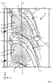
- An in Fig. 1 partially illustrated blade ring 10 comprises a plurality of circumferentially UR juxtaposed blades 12.
- the blades 12 have a respective pressure side 14, a suction side 16, and a front edge 18 and a trailing edge 20 on. Between two adjacent blades 12 is located between the suction side 16 of a first blade (lower blade in Fig. 1 ) and the pressure side 14 of a second blade 12 (upper blade in FIG Fig. 1 )
- the ring portion 10 is a circumferentially UR and in the axial direction AR extending surface which connects two adjacent blades 12 together.
- the blades 12 and the intermediate ring portions 22 are preferably formed integrally with each other, in particular, the blade ring 10 may be made of one or more casting (s).
- the flat annular section 22 has a contoured surface 24 which faces an annular space through which gas flows, into which the blades 12 protrude in the radial direction.
- contour lines are shown, wherein a zero line NL is shown in phantom. Starting from the zero line NL, the ring section 22 or its surface 24 rises in the radial direction to the outside, which is illustrated by the dotted contour lines +2 to +10.
- the annular section 22 or its surface recesses inward in the radial direction which is illustrated by the dashed contour lines -1 to -5.
- the numbers used for the contour lines are a qualitative illustration only and do not reflect real quantitative values.
- An indication +2 means So not that it is 2 units of a specific unit of measurement such as millimeters or tenths of a millimeter.
- the ring portion 22 has a direction indicated by the contour line +10 highest surface portion 26.
- This highest surface portion 26 abuts directly on the pressure side 14 of the blade 12.
- an imaginary connecting line VL which connects the leading edge 18 and the trailing edge 20 of the blade 12
- the highest surface portion 26 lies in the circumferential direction UR between this connecting line VL and the pressure side 14, preferably the highest surface portion 26 is complete, so with its entire surface (corresponding approximately to the boundary by the contour line +10) within a contour formed by the pressure side 14 and the connecting line VL.
- this center of gravity connecting line SL intersects the highest surface section 26.
- the ring section 22 or its surface 24 also has a deepest surface section 30, which is indicated by the contour line -5.
- This deepest surface portion 30 is adjacent to the suction side 16 of the blade 12. However, the deepest surface portion 30 is not directly on the suction side 16, but has a distance to the suction side 16 in the circumferential direction UR.
- the deepest surface portion 30 preferably also lies in the axial direction AR in front of the center of gravity connection line SL, wherein the reference "before” refers to the main flow direction of gas through the blade ring 10, which in the Fig. 1 illustrated by the double arrow SR.
- annular portion 22 Starting from the highest surface portion 26 of the annular portion 22 and its surface 24 drops along the pressure side 14 to the front edge 18 and the trailing edge 20 from. Further, the annular portion 22 also drops in the circumferential direction to the suction side 16 of the adjacent blade 12, in particular up to the level of the deepest surface portion 30, from where the ring portion to the suction side 16 again rises slightly.
- the highest surface portion 26 has a greater height than the depth or negative height of the deepest surface portion 30, in particular the height of highest surface portion 26 is about twice as large as the depth or negative height of the deepest surface portion 30 Height or the depth as absolute values (amounts) compared with each other without observing the corresponding sign with respect to the zero line.
- Fig. 2 shows a simplified longitudinal profile in the circumferential direction UR along the center of gravity connecting line SL of Fig. 1 between the pressure side 14 of the second (in the Fig. 1 upper) blade (12) and the suction side 16 of the first (in the Fig. 1 From the profile of the surface 24 of the annular section 22, it can be seen that the highest surface section 26 directly adjoins the pressure side 14 of the second blade 12.
- the highest surface portion 26 in this embodiment forms a kind of plateau at the illustrated level +10 with respect to the zero line NL.
- this highest surface portion 26 does not necessarily have to be flat, but may also have a curvature in itself. In this case, however, the curvature is so small that no position of the highest surface portion 26 reaches the level +12 or even higher. If the highest surface section has a singular high point, then it preferably lies directly against the pressure side 14 of the blade 12.
- the profile of the surface 24 then drops from the highest surface portion 26 towards the suction side 16 of the first blade 12 with partially different slopes, passes the zero level at NL, and continues to fall to the level -5. Starting from this level -5, the profile surface 24 then rises slightly in the direction of the suction side 16 before the ring section 22 merges into the suction side 16 of the first blade 12.
Abstract
Die Erfindung betrifft einen Schaufelring für eine Gasturbine, insbesondere Fluggasturbine, mit mehreren Schaufeln (12), die in Umfangsrichtung (UR) nebeneinander angeordnet sind, wobei die Schaufeln (12) einen sich im Wesentlichen in radialer Richtung erstreckenden Strömungsabschnitt aufweisen mit einer konvexen Saugseite (16), einer konkaven Druckseite (14), einer Vorderkante (18) und einer Hinterkante (20), wobei die Saugseite (16) und die Druckseite (14) durch die Vorderkante (18) und die Hinterkante (20) miteinander verbunden sind, wobei die Schaufeln (12) radial innen und/oder radial außen in einen Ringabschnitt (22) des Schaufelrings (10) übergehen, wobei der Ringabschnitt (22) eine erste Schaufel (12) und eine zweite Schaufel (12), die zueinander benachbart sind, zwischen der Saugseite (16) der ersten Schaufel (12) und der Druckseite (14) der zweiten Schaufel (12) verbindet. Erfindungsgemäß wird vorgeschlagen, dass der Ringabschnitt (22) als konturierte Fläche (24) ausgebildet ist mit in radialer Richtung unterschiedlichen Höhen, wobei der Ringabschnitt (22) einen höchsten Flächenabschnitt (26) und einen tiefsten Flächenabschnitt (30) aufweist, wobei der höchste Flächenabschnitt (26) direkt angrenzend an die Druckseite (14) der zweiten Schaufel (12) ausgebildet ist.The invention relates to a blade ring for a gas turbine, in particular an aircraft gas turbine, with a plurality of blades (12) arranged next to one another in the circumferential direction (UR), wherein the blades (12) have a substantially radially extending flow section with a convex suction side (UR). 16), a concave pressure side (14), a leading edge (18) and a trailing edge (20), wherein the suction side (16) and the pressure side (14) are interconnected by the leading edge (18) and the trailing edge (20), wherein the blades (12) merge radially inwardly and / or radially outwardly into a ring portion (22) of the blade ring (10), the ring portion (22) having a first blade (12) and a second blade (12) adjacent to one another , between the suction side (16) of the first blade (12) and the pressure side (14) of the second blade (12) connects. According to the invention, the ring section (22) is designed as a contoured surface (24) with different heights in the radial direction, the ring section (22) having a highest surface section (26) and a deepest surface section (30), the highest surface section (26) is formed directly adjacent to the pressure side (14) of the second blade (12).
Description
Die vorliegende Erfindung betrifft einen Schaufelring für eine Gasturbine, insbesondere Fluggasturbine, mit mehreren Schaufeln, die in Umfangsrichtung (UR) nebeneinander angeordnet sind, wobei die Schaufeln einen sich im Wesentlichen in radialer Richtung erstreckenden Strömungsabschnitt, das so genannte Schaufelblatt, aufweisen mit einer konvexen Saugseite, einer konkaven Druckseite, einer Vorderkante und einer Hinterkante, wobei die Saugseite und die Druckseite durch die Vorderkante und die Hinterkante miteinander verbunden sind, wobei die Schaufeln radial innen und/oder radial außen in einen Ringabschnitt des Schaufelrings übergehen, wobei der Ringabschnitt eine erste Schaufel und eine zweite Schaufel, die zueinander benachbart sind, zwischen der Saugseite der ersten Schaufel und der Druckseite der zweiten Schaufel verbindet. Ein derartiger Ringabschnitt wird auch als radial äußeres bzw. radial inneres Deckband bzw. "end wall" bezeichnet.The present invention relates to a blade ring for a gas turbine, in particular an aircraft gas turbine, with a plurality of blades arranged in the circumferential direction (UR) side by side, said blades having a substantially radially extending flow portion, the so-called airfoil, with a convex suction side a concave pressure side, a leading edge and a trailing edge, the suction side and the pressure side being interconnected by the leading edge and the trailing edge, the blades passing radially inward and / or radially outward into a ring portion of the blade ring, the ring portion being a first blade and a second blade, which are adjacent to each other, connects between the suction side of the first blade and the pressure side of the second blade. Such a ring portion is also referred to as a radially outer or radially inner shroud or "end wall".
Richtungsangaben wie "Axial-" bzw. "axial", "Radial-" bzw. "radial" und "Umfangs-" sind grundsätzlich auf die Maschinenachse der Gasturbine bezogen zu verstehen, sofern sich aus dem Kontext nicht explizit oder implizit etwas anderes ergibt. Weitere Angaben wie "vorne" oder "hinten" beziehen sich grundsätzlich auf die Hauptströmungsrichtung von Gas in einer Gasturbine bzw. in zugehörigen Turbinen- bzw. Verdichterstufen, sofern sich aus dem Kontext nicht explizit oder implizit etwas anderes ergibt.Directional information such as "axial" or "axial", "radial" or "radial" and "circumferential" are basically based on the machine axis of the gas turbine to understand, unless the context explicitly or implicitly otherwise results. Further details, such as "forward" or "rearward", generally refer to the main flow direction of gas in a gas turbine or in associated turbine or compressor stages, unless the context explicitly or implicitly indicates otherwise.
Bei Schaufelringen von Gasturbinen ergeben sich zu einer Hauptströmungsrichtung, die im Wesentlichen tangential zur Beschaufelung verläuft, auch Strömungen quer dazu sowie entsprechende Strömungswirbel. Diese Querströmungen und die Strömungswirbel, welche zusammen auch Sekundärströmung genannt werden, sind störend und wirken sich nachteilig auf den Wirkungsgrad der Gasturbine aus aufgrund von ungünstigen aerodynamischen Strömungsbedingungen.In blade rings of gas turbines resulting in a main flow direction, which is substantially tangential to the blading, and flows transverse thereto and corresponding flow vortices. These transverse flows and the flow vortices, which together are also called secondary flow, are disturbing and adversely affect the efficiency of the gas turbine due to unfavorable aerodynamic flow conditions.
Aufgabe der Erfindung ist es, einen Schaufelring bereitzustellen, bei dem die obigen Nachteile vermieden werden können.The object of the invention is to provide a blade ring in which the above disadvantages can be avoided.
Zur Lösung dieser Aufgabe wird vorgeschlagen, dass der Ringabschnitt als konturierte Fläche ausgebildet ist mit in radialer Richtung unterschiedlichen Höhen, wobei der Ringabschnitt einen höchsten Flächenabschnitt und einen tiefsten Flächenabschnitt aufweist, wobei der höchste Flächenabschnitt direkt angrenzend an die Druckseite der zweiten Schaufel ausgebildet ist.To solve this problem, it is proposed that the ring portion is formed as a contoured surface with different heights in the radial direction, wherein the ring portion has a highest surface portion and a deepest surface portion, wherein the highest surface portion is formed directly adjacent to the pressure side of the second blade.
Im Sinne der vorliegenden Erfindung wird dabei unter dem "radial höchsten Flächenabschnitt" ein Flächenabschnitt des Ringabschnitts verstanden, welcher sich am weitesten in den zwischen zwei in Umfangsrichtung benachbarten Schaufeln gebildeten Strömungskanal hineinersteckt. Dementsprechend wird unter einem "radial tiefsten Flächenabschnitt" ein Flächenabschnitt verstanden, welcher sich am wenigstens weit in den zwischen zwei in Umfangsrichtung benachbarten Schaufeln gebildeten Strömungskanal hineinersteckt. Mit anderen Worten sind die Begriffe "höchster" und "tiefster" hier auf das Volumen des Strömungskanals bezogen. Bei einem radial inneren Ringabschnitt, auf welchen sich die vorliegende Erfindung bevorzugt bezieht, weist somit der "radial höchste Flächenabschnitt" einen größeren Abstand zur Rotations- oder Maschinenachse der Strömungsmaschine auf als der "radial tiefste Flächenabschnitt", wenn der Schaufelring bestimmungsgemäß in einer Strömungsmaschine montiert ist, wohingegen sich dies in einem radial äußeren Ringabschnitt genau umgekehrt verhält.In the context of the present invention, the "radially highest area section" is understood to mean a surface section of the ring section which fits in the furthest into the flow channel formed between two blades which are adjacent in the circumferential direction. Accordingly, a "radially deepest surface portion" is understood to mean a surface portion which extends at least far into the flow channel formed between two blades which are adjacent in the circumferential direction. In other words, the terms "highest" and "lowest" here refer to the volume of the flow channel. In a radially inner ring portion, to which the present invention preferably relates, thus has the "radially highest surface portion" a greater distance from the rotational or machine axis of the turbomachine than the "radially lowest surface portion" when the blade ring mounted as intended in a turbomachine whereas in a radially outer ring section this is exactly the opposite.
Eine derartige Ausgestaltung der Ringabschnitte zwischen zwei benachbarten Schaufeln führt zu einer verbesserten aerodynamischen Strömung in den Randbereichen der Druckseite der Schaufeln. Der höchste Flächenabschnitt oder ein höchster Punkt des Ringabschnitts liegt dabei genau an der Druckseite des Schaufelprofils an.Such a configuration of the ring sections between two adjacent blades leads to an improved aerodynamic flow in the edge regions of the pressure side of the blades. The highest area section or a highest point of the ring section lies exactly on the pressure side of the blade profile.
Vorzugsweise liegt der höchste Flächenabschnitt zwischen der Druckseite und einer gedachten Verbindungslinie, welche die Vorderkante und die Hinterkante der zweiten Schaufel verbindet.Preferably, the highest surface portion is between the pressure side and an imaginary connection line connecting the leading edge and the trailing edge of the second blade.
Weiterbildend wird vorgeschlagen, dass der tiefste Flächenabschnitt benachbart zur Saugseite der ersten Schaufel angeordnet ist, wobei der Ringabschnitt vom tiefsten Flächenabschnitt zur Saugsseite hin ein ansteigendes Profil aufweist.In a further development, it is proposed that the deepest surface section is arranged adjacent to the suction side of the first blade, wherein the ring section has an ascending profile from the deepest surface section to the suction side.
Das hier unter Bezugnahme auf eine erste Schaufel und eine zweite Schaufel Gesagte gilt selbstverständlich für jedes Schaufelpaar des Schaufelringes, das durch zwei benachbarte Schaufeln gebildet wird. Die Verwendung von "erster" und "zweiter" dient lediglich der besseren Ansprechbarkeit der benachbarten Schaufeln, stellt aber keineswegs eine Einschränkung auf zwei spezifische Schaufeln des Schaufelrings dar. Insoweit ist die Ausgestaltung aller Ringabschnitte zwischen den Schaufeln des Schaufelrings gleich.The above with reference to a first blade and a second blade, of course, applies to each pair of blades of the blade ring, which is formed by two adjacent blades. The use of "first" and "second" only serves the better responsiveness of the adjacent blades, but by no means a limitation on two specific blades of the blade ring. In that regard, the design of all ring sections between the blades of the blade ring is the same.
Die Lage der höchsten Flächenabschnitte ist bevorzugt so gewählt, dass die höchsten Flächenabschnitte zumindest abschnittsweise, vorzugsweise vollständig, in einen Axialereich liegen, der sich von maximal 15% der axialen Erstreckung der Schaufel stromaufwärts bis maximale 15% der axialen Erstreckung der Schaufel stromabwärts in Bezug auf eine gedachte Verbindungslinie erstreckt, welche die Schwerpunkte einer Querschnittsfläche der Schaufeln in Umfangsrichtung (UR) verbindet. Insbesondere kann die Lage der höchsten Flächenabschnitte so gewählt sein, dass die gedachte Verbindungslinie die höchsten Flächenabschnitte schneidet.The position of the highest surface portions is preferably selected so that the highest surface portions are at least partially, preferably completely, in an axial region extending from a maximum of 15% of the axial extent of the blade upstream to a maximum of 15% of the axial extent of the blade downstream with respect to extends an imaginary connecting line which connects the centers of gravity of a cross-sectional area of the blades in the circumferential direction (UR). In particular, the position of the highest surface portions may be selected such that the imaginary connection line intersects the highest surface portions.
Die tiefsten Flächenabschnitte können in axialer Richtung (AR) vor der Verbindungslinie liegen. In der Regel schneidet die gedachte Verbindungslinie die tiefsten Flächenabschnitte nicht.The deepest surface sections can lie in the axial direction (AR) in front of the connecting line. As a rule, the imaginary connecting line does not intersect the deepest surface sections.
Weiter ist es bevorzugt, dass die Kontur des Ringabschnitts vom höchsten Flächenabschnitt aus entlang der Druckseite der zweiten Schaufel zur Vorderkante und zur Hinterkante der zweiten Schaufel hin und zur Saugseite der ersten Schaufel hin abfällt.Further, it is preferable that the contour of the annular portion drops from the highest surface portion along the pressure side of the second blade toward the leading edge and the trailing edge of the second blade toward the suction side of the first blade.
Bezogen auf eine Nulllinie wird vorgeschlagen, dass der höchste Flächenabschnitt eine größere Höhe aufweist als die Tiefe bzw. negative Höhe des tiefsten Flächenabschnitts, insbesondere ist der Absolutwert (Betrag) der Höhe des höchsten Flächenabschnitts etwa doppelt so groß wie der Absolutwert (Betrag) der Tiefe bzw. negativen Höhe des tiefsten Flächenabschnitts.With reference to a zero line, it is proposed that the highest area section has a greater height than the depth or negative height of the deepest area section; in particular, the absolute value (magnitude) of the height of the highest area section is about twice as large as the absolute value (magnitude) of the depth or negative height of the deepest surface section.
Die Erfindung betrifft auch einen Laufschaufelring einer Turbinenstufe einer Gasturbine, insbesondere Fluggasturbine, wobei der Laufschaufelring als Schaufelring mit einem der oben beschriebenen Merkmale ausgebildet ist.The invention also relates to a blade ring of a turbine stage of a gas turbine, in particular aircraft gas turbine, wherein the blade ring is formed as a blade ring with one of the features described above.
Ferner betrifft die Erfindung einen Leitschaufelring einer Turbinenstufe einer Gasturbine, insbesondere Fluggasturbine, wobei der Leitschaufelring als Schaufelring mit einem der oben beschriebenen Merkmale ausgebildet ist.Furthermore, the invention relates to a guide blade ring of a turbine stage of a gas turbine, in particular aircraft gas turbine, wherein the guide blade ring is formed as a blade ring with one of the features described above.
Schließlich betrifft die Erfindung auch eine Gasturbine, insbesondere Fluggasturbine, die wenigstens einen Schaufelring oder Laufschaufelring oder Leitschaufelring mit einem der oben beschriebenen Merkmale aufweist.Finally, the invention also relates to a gas turbine, in particular an aircraft gas turbine, which has at least one blade ring or blade ring or guide blade ring with one of the features described above.
Nachfolgend wird die Erfindung unter Bezugnahme auf die anliegenden Figuren beispielhaft und nicht einschränkend beschrieben.
-
Fig. 1 zeigt eine vereinfachte schematische Perspektivdarstellung eines Ausschnitts eines Schaufelrings mit Höhenlinien, welche die Kontur eines Ringabschnitts repräsentieren. -
Fig. 2 zeigt ein vereinfachtes qualitatives Längsprofil eines Ringabschnitts zwischen zwei Schaufeln entlang einer Linie SL derFig. 1
-
Fig. 1 shows a simplified schematic perspective view of a section of a blade ring with contour lines, which represent the contour of a ring portion. -
Fig. 2 shows a simplified qualitative longitudinal profile of a ring section between two blades along a line SL ofFig. 1
Ein in
Der flächige Ringabschnitt 22 weist eine konturierte Oberfläche 24 auf, die einem von Gas durchströmten Ringraum zugewandt ist, in den die Schaufeln 12 in radialer Richtung vorstehen. In
Der Ringabschnitt 22 weist einen durch die Höhenlinie +10 angedeuteten höchsten Flächenabschnitt 26 auf. Dieser höchste Flächenabschnitt 26 liegt unmittelbar an der Druckseite 14 der Schaufel 12 an. Nimmt man eine gedachte Verbindungslinie VL, welche die Vorderkante 18 und die Hinterkante 20 der Schaufel 12 verbindet, liegt die höchste Flächenabschnitt 26 in Umfangsrichtung UR zwischen dieser Verbindungslinie VL und der Druckseite 14, vorzugsweise liegt der höchste Flächenabschnitt 26 vollständig, also mit seiner gesamten Fläche (entsprechend etwa der Begrenzung durch die Höhenlinie +10) innerhalb einer Kontur, die von der Druckseite 14 und der Verbindungslinie VL gebildet wird. Nimmt man für benachbarte Schaufeln 12 einen jeweiligen Schwerpunkt 28 einer Querschnittsfläche des Schaufelprofils an und verbindet diese Schwerpunkte 28 in Umfangrichtung UR, schneidet diese Schwerpunktverbindungslinie SL den höchsten Flächenabschnitt 26.The
Der Ringabschnitt 22 bzw. seine Oberfläche 24 weist ferner einen tiefsten Flächenabschnitt 30 auf, der durch die Höhenlinie -5 angedeutet wird. Dieser tiefste Flächenabschnitt 30 liegt benachbart zur Saugseite 16 der Schaufel 12. Allerdings liegt der tiefste Flächenabschnitt 30 nicht unmittelbar an der Saugseite 16 an, sondern weist in Umfangsrichtung UR einen Abstand zur Saugseite 16 auf. Der tiefste Flächenabschnitt 30 liegt bevorzugt auch in axialer Richtung AR vor der Schwerpunktverbindungslinie SL, wobei der Bezug "vor" sich auf die Hauptströmungsrichtung von Gas durch den Schaufelring 10 bezieht, welche in der
Ausgehend von dem höchsten Flächenabschnitt 26 fällt der Ringabschnitt 22 bzw. dessen Oberfläche 24 entlang der Druckseite 14 zur Vorderkante 18 und zur Hinterkante 20 ab. Ferner fällt der Ringabschnitt 22 auch in Umfangsrichtung zur Saugseite 16 der benachbarten Schaufel 12 ab, insbesondere bis auf das Niveau des tiefsten Flächenabschnitts 30, von wo aus der Ringabschnitt zur Saugseite 16 hin wieder etwas ansteigt.Starting from the
Geht man davon aus, dass zwischen zwei Höhenlinien sowohl in Plusrichtung als auch in Minusrichtung der gleiche Abstand in radialer Richtung vorliegt, weist der höchste Flächenabschnitt 26 eine größere Höhe auf als die Tiefe bzw. negative Höhe des tiefsten Flächenabschnitts 30, insbesondere ist die Höhe des höchsten Flächenabschnitts 26 etwa doppelt so groß wie die Tiefe bzw. negative Höhe des tiefsten Flächenabschnitts 30. Dabei werden die Höhe bzw. die Tiefe als absolute Werte (Beträge) miteinander verglichen ohne das entsprechende Vorzeichen bezüglich der Nulllinie zu beachten.Assuming that the same distance in the radial direction exists between two contour lines both in the plus direction and in the minus direction, the
Allerdings muss dieser höchste Flächenabschnitt 26 nicht zwingend eben ausgebildet sein, sondern kann auch in sich eine Krümmung aufweisen. In diesem Fall ist die Krümmung jedoch so gering, dass keine Stelle des höchsten Flächenabschnitts 26 das Niveau +12 erreicht oder gar darüber liegt. Weist der höchste Flächenabschnitt einen singulären Hochpunkt auf, so liegt dieser vorzugsweise unmittelbar an der Druckseite 14 der Schaufel 12 an.However, this
Das Profil der Oberfläche 24 fällt dann von dem höchsten Flächenabschnitt 26 in Richtung der Saugseite 16 der ersten Schaufel 12 mit teilweise unterschiedlichen Steigungen ab, passiert das Nullniveau bei NL und fällt weiter ab bis auf das Niveau -5. Ausgehend von diesem Niveau -5 steigt das Profil Oberfläche 24 dann in Richtung der Saugseite 16 leicht an, bevor der Ringabschnitt 22 in die Saugseite 16 der ersten Schaufel 12 übergeht.The profile of the
In der schematischen Schnittansicht der
Durch die vorgestellte Konturierung des Ringabschnitts 22 zwischen zwei benachbarten Schaufeln 12 eines Schaufelrings, können insbesondere durch die Anordnung des höchsten Flächenabschnitts 26 direkt anschließend an die Druckseite 14 verbesserte aerodynamische Strömungsverhältnisse erreicht werden, die zu einer verbesserten Effizienz und einem verbesserten Wirkungsgrad der Gasturbine führen.By the presented contouring of the
- 1010
- Schaufelringblade ring
- 1212
- Schaufelshovel
- 1414
- Druckseitepressure side
- 1616
- Saugseitesuction
- 1818
- Vorderkanteleading edge
- 2020
- Hinterkantetrailing edge
- 2222
- Ringabschnittring section
- 2424
- Oberflächesurface
- 2626
- Höchster FlächenabschnittHighest surface section
- 2828
- Schwerpunktmain emphasis
- 3030
- Tiefster FlächenabschnittLowest surface section
- ARAR
- Axialrichtungaxially
- NLNL
- Nullniveau bzw. NulllinieZero level or zero line
- URUR
- Umfangsrichtungcircumferential direction
- VLVL
- Verbindungslinieconnecting line
- SLSL
- SchwerpunktverbindungsliniePriority connecting line
- SRSR
- HauptströmungslinieMainstream line
Claims (10)
Applications Claiming Priority (1)
| Application Number | Priority Date | Filing Date | Title |
|---|---|---|---|
| DE102015224420.2A DE102015224420A1 (en) | 2015-12-07 | 2015-12-07 | Annular space contouring of a gas turbine |
Publications (1)
| Publication Number | Publication Date |
|---|---|
| EP3179036A1 true EP3179036A1 (en) | 2017-06-14 |
Family
ID=57442557
Family Applications (1)
| Application Number | Title | Priority Date | Filing Date |
|---|---|---|---|
| EP16201371.8A Withdrawn EP3179036A1 (en) | 2015-12-07 | 2016-11-30 | Ring area contouring of a gas turbine |
Country Status (3)
| Country | Link |
|---|---|
| US (1) | US20170159443A1 (en) |
| EP (1) | EP3179036A1 (en) |
| DE (1) | DE102015224420A1 (en) |
Cited By (1)
| Publication number | Priority date | Publication date | Assignee | Title |
|---|---|---|---|---|
| EP3428391A1 (en) * | 2017-07-14 | 2019-01-16 | MTU Aero Engines GmbH | Blade grid of a turbomachine |
Families Citing this family (4)
| Publication number | Priority date | Publication date | Assignee | Title |
|---|---|---|---|---|
| DE102015224376A1 (en) * | 2015-12-04 | 2017-06-08 | MTU Aero Engines AG | Bucket channel, blade grid and turbomachine |
| ES2857568T3 (en) * | 2017-02-06 | 2021-09-29 | MTU Aero Engines AG | Contouring of a pallet from a pallet rack |
| JP7232034B2 (en) * | 2018-12-18 | 2023-03-02 | 三菱重工業株式会社 | Turbine blade and steam turbine having the same |
| DE102020206365A1 (en) | 2020-05-20 | 2021-11-25 | turbonik GmbH | Flow guiding device for a turbo machine |
Citations (7)
| Publication number | Priority date | Publication date | Assignee | Title |
|---|---|---|---|---|
| US20060233641A1 (en) * | 2005-04-14 | 2006-10-19 | General Electric Company | Crescentic ramp turbine stage |
| US20070258817A1 (en) * | 2006-05-02 | 2007-11-08 | Eunice Allen-Bradley | Blade or vane with a laterally enlarged base |
| WO2009129786A1 (en) * | 2008-04-26 | 2009-10-29 | Mtu Aero Engines Gmbh | Reproduced flow path of an axial turbomachine in order to reduce secondary flow |
| US20100143139A1 (en) * | 2008-12-09 | 2010-06-10 | Vidhu Shekhar Pandey | Banked platform turbine blade |
| EP2423437A2 (en) * | 2010-08-31 | 2012-02-29 | General Electric Company | Turbine assembly with end-wall-contoured airfoils and preferential clocking |
| US20120051900A1 (en) * | 2010-08-31 | 2012-03-01 | General Electric Company | Turbine nozzle with contoured band |
| WO2014105102A1 (en) * | 2012-12-28 | 2014-07-03 | United Technologies Corporation | Platform with curved edges adjacent suction side of airfoil |
Family Cites Families (2)
| Publication number | Priority date | Publication date | Assignee | Title |
|---|---|---|---|---|
| US8439643B2 (en) * | 2009-08-20 | 2013-05-14 | General Electric Company | Biformal platform turbine blade |
| US20120051930A1 (en) * | 2010-08-31 | 2012-03-01 | General Electric Company | Shrouded turbine blade with contoured platform and axial dovetail |
-
2015
- 2015-12-07 DE DE102015224420.2A patent/DE102015224420A1/en not_active Withdrawn
-
2016
- 2016-11-30 EP EP16201371.8A patent/EP3179036A1/en not_active Withdrawn
- 2016-12-02 US US15/367,799 patent/US20170159443A1/en not_active Abandoned
Patent Citations (7)
| Publication number | Priority date | Publication date | Assignee | Title |
|---|---|---|---|---|
| US20060233641A1 (en) * | 2005-04-14 | 2006-10-19 | General Electric Company | Crescentic ramp turbine stage |
| US20070258817A1 (en) * | 2006-05-02 | 2007-11-08 | Eunice Allen-Bradley | Blade or vane with a laterally enlarged base |
| WO2009129786A1 (en) * | 2008-04-26 | 2009-10-29 | Mtu Aero Engines Gmbh | Reproduced flow path of an axial turbomachine in order to reduce secondary flow |
| US20100143139A1 (en) * | 2008-12-09 | 2010-06-10 | Vidhu Shekhar Pandey | Banked platform turbine blade |
| EP2423437A2 (en) * | 2010-08-31 | 2012-02-29 | General Electric Company | Turbine assembly with end-wall-contoured airfoils and preferential clocking |
| US20120051900A1 (en) * | 2010-08-31 | 2012-03-01 | General Electric Company | Turbine nozzle with contoured band |
| WO2014105102A1 (en) * | 2012-12-28 | 2014-07-03 | United Technologies Corporation | Platform with curved edges adjacent suction side of airfoil |
Cited By (2)
| Publication number | Priority date | Publication date | Assignee | Title |
|---|---|---|---|---|
| EP3428391A1 (en) * | 2017-07-14 | 2019-01-16 | MTU Aero Engines GmbH | Blade grid of a turbomachine |
| US10876410B2 (en) | 2017-07-14 | 2020-12-29 | MTU Aero Engines AG | Turbomachine airfoil array |
Also Published As
| Publication number | Publication date |
|---|---|
| US20170159443A1 (en) | 2017-06-08 |
| DE102015224420A1 (en) | 2017-06-08 |
Similar Documents
| Publication | Publication Date | Title |
|---|---|---|
| EP2787171B1 (en) | Blade grid with side wall contours and turbomachine | |
| EP2696029B1 (en) | Blade row with side wall contours and fluid flow engine | |
| EP3179036A1 (en) | Ring area contouring of a gas turbine | |
| EP2487329B1 (en) | Blade canal with side wall contours and corresponding fluid flow engine | |
| EP2463480B1 (en) | Blade with hybrid airfoil | |
| CH697806A2 (en) | Turbine blade shroud edge profile. | |
| DE102005025213A1 (en) | Blade of an axial flow machine | |
| EP2835499B1 (en) | Blade row and corresponding flow machine | |
| DE102007020025A1 (en) | Shape of a gas channel in an axial flow gas turbine engine | |
| EP2746533B1 (en) | Blade grid and turbomachine | |
| EP2558685B1 (en) | Guide vane | |
| EP3260660B1 (en) | Rotor or stator vane having raised areas | |
| EP3225781A2 (en) | Blade channel, blade row and turbomachine | |
| EP3388626B1 (en) | Contouring of a blade row platform | |
| EP2597257B1 (en) | Blades | |
| EP2806103A1 (en) | Cascade, blades and flow engine | |
| EP3401504A1 (en) | Blade grid | |
| EP2730745B1 (en) | Blade assembly for a turbo engine | |
| DE112016000685T5 (en) | TURBINE AND GAS TURBINE | |
| EP3358135B1 (en) | Contouring of a blade row platform | |
| DE102013213416A1 (en) | Shovel for a gas turbine machine | |
| EP3375977A1 (en) | Contouring of a platform in an airfoil cascade | |
| DE102020130637A1 (en) | Transition channel for a turbo machine as well as a turbo machine | |
| EP3404211A1 (en) | Blade cascade segment for a turbine with contoured platform surface, corresponding blade cascade, blade channel, platform, turbine and aircraft engine | |
| EP3369892B1 (en) | Contouring of a blade row platform |
Legal Events
| Date | Code | Title | Description |
|---|---|---|---|
| PUAI | Public reference made under article 153(3) epc to a published international application that has entered the european phase |
Free format text: ORIGINAL CODE: 0009012 |
|
| AK | Designated contracting states |
Kind code of ref document: A1 Designated state(s): AL AT BE BG CH CY CZ DE DK EE ES FI FR GB GR HR HU IE IS IT LI LT LU LV MC MK MT NL NO PL PT RO RS SE SI SK SM TR |
|
| AX | Request for extension of the european patent |
Extension state: BA ME |
|
| STAA | Information on the status of an ep patent application or granted ep patent |
Free format text: STATUS: THE APPLICATION IS DEEMED TO BE WITHDRAWN |
|
| 18D | Application deemed to be withdrawn |
Effective date: 20171215 |