EP3177530B1 - Hole-filling sleeve and washer design for bolt installation - Google Patents
Hole-filling sleeve and washer design for bolt installation Download PDFInfo
- Publication number
- EP3177530B1 EP3177530B1 EP15722621.8A EP15722621A EP3177530B1 EP 3177530 B1 EP3177530 B1 EP 3177530B1 EP 15722621 A EP15722621 A EP 15722621A EP 3177530 B1 EP3177530 B1 EP 3177530B1
- Authority
- EP
- European Patent Office
- Prior art keywords
- washer
- sleeve
- bolt member
- opening
- shaft
- Prior art date
- Legal status (The legal status is an assumption and is not a legal conclusion. Google has not performed a legal analysis and makes no representation as to the accuracy of the status listed.)
- Active
Links
Images


Classifications
-
- F—MECHANICAL ENGINEERING; LIGHTING; HEATING; WEAPONS; BLASTING
- F16—ENGINEERING ELEMENTS AND UNITS; GENERAL MEASURES FOR PRODUCING AND MAINTAINING EFFECTIVE FUNCTIONING OF MACHINES OR INSTALLATIONS; THERMAL INSULATION IN GENERAL
- F16B—DEVICES FOR FASTENING OR SECURING CONSTRUCTIONAL ELEMENTS OR MACHINE PARTS TOGETHER, e.g. NAILS, BOLTS, CIRCLIPS, CLAMPS, CLIPS OR WEDGES; JOINTS OR JOINTING
- F16B43/00—Washers or equivalent devices; Other devices for supporting bolt-heads or nuts
-
- B—PERFORMING OPERATIONS; TRANSPORTING
- B23—MACHINE TOOLS; METAL-WORKING NOT OTHERWISE PROVIDED FOR
- B23P—METAL-WORKING NOT OTHERWISE PROVIDED FOR; COMBINED OPERATIONS; UNIVERSAL MACHINE TOOLS
- B23P19/00—Machines for simply fitting together or separating metal parts or objects, or metal and non-metal parts, whether or not involving some deformation; Tools or devices therefor so far as not provided for in other classes
- B23P19/04—Machines for simply fitting together or separating metal parts or objects, or metal and non-metal parts, whether or not involving some deformation; Tools or devices therefor so far as not provided for in other classes for assembling or disassembling parts
- B23P19/06—Screw or nut setting or loosening machines
-
- B—PERFORMING OPERATIONS; TRANSPORTING
- B64—AIRCRAFT; AVIATION; COSMONAUTICS
- B64D—EQUIPMENT FOR FITTING IN OR TO AIRCRAFT; FLIGHT SUITS; PARACHUTES; ARRANGEMENT OR MOUNTING OF POWER PLANTS OR PROPULSION TRANSMISSIONS IN AIRCRAFT
- B64D45/00—Aircraft indicators or protectors not otherwise provided for
- B64D45/02—Lightning protectors; Static dischargers
-
- F—MECHANICAL ENGINEERING; LIGHTING; HEATING; WEAPONS; BLASTING
- F16—ENGINEERING ELEMENTS AND UNITS; GENERAL MEASURES FOR PRODUCING AND MAINTAINING EFFECTIVE FUNCTIONING OF MACHINES OR INSTALLATIONS; THERMAL INSULATION IN GENERAL
- F16B—DEVICES FOR FASTENING OR SECURING CONSTRUCTIONAL ELEMENTS OR MACHINE PARTS TOGETHER, e.g. NAILS, BOLTS, CIRCLIPS, CLAMPS, CLIPS OR WEDGES; JOINTS OR JOINTING
- F16B19/00—Bolts without screw-thread; Pins, including deformable elements; Rivets
- F16B19/02—Bolts or sleeves for positioning of machine parts, e.g. notched taper pins, fitting pins, sleeves, eccentric positioning rings
-
- F—MECHANICAL ENGINEERING; LIGHTING; HEATING; WEAPONS; BLASTING
- F16—ENGINEERING ELEMENTS AND UNITS; GENERAL MEASURES FOR PRODUCING AND MAINTAINING EFFECTIVE FUNCTIONING OF MACHINES OR INSTALLATIONS; THERMAL INSULATION IN GENERAL
- F16B—DEVICES FOR FASTENING OR SECURING CONSTRUCTIONAL ELEMENTS OR MACHINE PARTS TOGETHER, e.g. NAILS, BOLTS, CIRCLIPS, CLAMPS, CLIPS OR WEDGES; JOINTS OR JOINTING
- F16B5/00—Joining sheets or plates, e.g. panels, to one another or to strips or bars parallel to them
- F16B5/02—Joining sheets or plates, e.g. panels, to one another or to strips or bars parallel to them by means of fastening members using screw-thread
Definitions
- This invention relates to fasteners and more particularly to fasteners that utilize a sleeve in providing hole filling connections between at least two elements that are being joined together by the fastener
- Fasteners are utilized in joining at least two elements or components together in the process of assembling many items of manufacture.
- a number of items of manufacture are sensitive to an occurrence of sparking caused by electromagnetic effects to which the items may be exposed.
- Such items are ones that are exposed to the environment and could be exposed to unfavorable weather conditions such as lightning.
- Those items that are exposed to lightning do not want to be subject to sparking induced by the electromagnetic effects.
- secure electrical contacts need to be achieved by fasteners that connect two or more elements or components together in assembling the item of manufacture. Failure to make secure electrical connections between the materials being joined together by a fastener and the fastener will provide a condition where unwanted sparking may occur.
- DE102007026733 discloses a head plate used to fasten insulation and sealing strips onto flat roofs, comprises plastic disc with depression in form of circular cylindrical chamber.
- US2005013678 discloses a three piece blind fastener comprising a mandrel, a tubular body portion and a radially extending flange.
- US3641865 A discloses a sealing shear fastener comprises a three-part structure arranged for interengagement for joining pieces or for filling a hole.
- WO2011050040 discloses a sleeve interference fastener adapted to be installed in a hole of a structure.
- GB1478462 discloses a captive washer for a fastener assembly.
- US2010124472 discloses a conductive sleeved fastener assembly.
- It is another object of the present invention to provide a method for using a fastener assembly which includes the step inserting a first end portion of a sleeve into and through a first end of a hole, wherein the hole is defined by at least two elements to be joined together and extends through the at least two elements such that a first end of the first end portion of the sleeve is positioned outside of a second end of the hole.
- the method also includes the step of positioning a washer, wherein the washer comprises a body which defines a first side and an opposing second side and defines an opening which extends from the first side toward the second side, wherein the opening positioned at the first side defines a diameter greater than the outside diameter of the sleeve, wherein the body defines a recess which extends from the second side toward the first side, wherein a diameter of the recess is greater than the diameter of the opening and wherein the recess and the opening are in communication with one another, such that the first end portion of the sleeve extends through the opening and the recess of the washer with a first end of the first end portion of the sleeve positioned outside of the recess with the recess facing in a direction toward the first end of the sleeve.
- FIG. 1 an example of a prior art fastener assembly 10 is shown which is used to provide an interference fit with components it is joining together.
- This assembly utilizes a bolt member 12 selected to fit within a particular tapered sleeve 14.
- Bolt member 12 includes a head 16, central shaft 18, transition section 20 and threaded portion 22 (threads not shown).
- Tapered sleeve 14 defines an internal opening 24 wherein the opening 24 decreases in diameter in a lower section 26 of sleeve 14 and at an opposing end of sleeve 14 collar 28 is positioned surrounding sleeve 14.
- bolt member 12 and sleeve 14 With bolt member 12 and sleeve 14 inserted into the hole defined in the components to be joined together, bolt member 12 and sleeve 14 are positioned relative to one another, as shown in FIG. 1 .
- a nut (not shown) is engaged onto threaded portion 22 (not shown) and tightened.
- bolt member 12 moves moved toward the nut and central shaft 18 of bolt member 12 begins to push against wall 30 of lower section 26 of tapered sleeve 14.
- central shaft 18 moves toward the nut and pushes section 26 outwardly and against an interior surface of the hole of the components being joined together forming an interference fit with the components.
- the interference fit promotes electrical contact with the components being joined together to prevent sparking from electromagnetic effects.
- fastener assembly 10 which utilized a non-tapered or rather straight cylindrical sleeve.
- an oversized bolt member was inserted into the sleeve and with the application of force was applied to the bolt member pushing it through the sleeve, thereby pushing the wall of the sleeve in an outward direction creating an interference fit within the hole positioned in components being joined.
- the bolt member pushed on the wall of the sleeve in a lateral or outward direction to make the sleeve create an interference fit with the components being joined.
- the target hole diameter would need to be 2.147 cm (0.8455 inches) in contrast as the grip length increases to 61-90 units the target hole diameter would need to be 2.346 cm (0.9235 inches) in diameter so as to accommodate the proper interference fit.
- greater diameter dimension would be needed for both the bolt member and the sleeve to create the proper interference fit.
- Components that are to be joined together in assembling an item of manufacture may include all metal components, all composite materials or a combination of metal and composite materials.
- a secure and reliable interference fit with composite materials must assure good electrical contact is made with the carbon conductive fibers within the composite material.
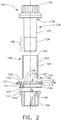
- Assembly 100 includes sleeve 102 which is configured or constructed in a cylindrical shape having a first end portion 104 and a second end portion 106. With its cylindrical shape, sleeve 102 has an outside diameter and correspondingly an interior diameter. Sleeve 102 is constructed of metal to provide strong connector, as are the other components of fastener assembly 100, and also to provide high quality electrical conductivity.
- Washer 108 receives and engages sleeve 102.
- Washer 108 has body 110 which defines a first side 112 and an opposing second side 114.
- First side 112 defines a flat annular surface 116 and second side 114 defines another flat annular surface 118.
- Body 110 defines an opening 120 which extends from first side 112 toward the second side 114. Opening 120 defines a diameter greater than the outside diameter of the sleeve 102.
- Body110 of washer 108 defines a recess 122 which has a diameter greater than the diameter of opening 120 and which extends from the second side 114 toward the first side 112 such that recess 122 and opening 120 communicate with one another.
- Opening 120 increases in diameter as opening 120 extends from first side 112 toward second side 114.
- sidewall 124 which extends from first side 112 toward the second side 114 forms a planar surface and forms an acute angle with annular surface 116 of first side 112.
- Sidewall 124 extends to recess 122 whereat it intersects with flat annular surface 126 which surrounds opening 120 with which recess 122 communicates.
- diameter of opening 120 is greater than the outside diameter of sleeve 102 to allow sleeve 102 to pass through opening 120.
- Recess 122 has a diameter greater than opening 120 and of sleeve 102 wherein sleeve 102 can pass through recess 122.
- Bolt member 128 includes head 130 and shaft 132.
- Shaft 132 has a diameter smaller than an inside diameter of the sleeve 102 and defines threads 134 (not shown) along a portion 136 of shaft 132.
- Transition portion 138 of shaft 132 extends from shaft 132 to head 130.
- Transition portion 138 of shaft 132 is configured to extend away from shaft 132 in a curved direction toward head 130.
- portion 136 of the shaft 132 which defines threads (not shown) extends from first end 140 of first end portion 104 of the sleeve 102 and second end 142 of second end portion 106 of sleeve 102 is in contact with head 130 of the bolt member 128.
- another washer 144 is positioned to overlie washer 108.
- Another washer 144 includes a body 146 which defines an opening 148 through body 146 of other washer 144.
- opening 148 has a greater diameter than the diameter of shaft 132 of bolt member 128.
- the diameter of opening 148 is smaller than outside diameter of sleeve 102. This enables first end portion 104 of sleeve 102 to extend through opening 120 and recess 122 and beyond recess 122, as seen in FIG. 3 , and position first end 140 of first end portion 104 of sleeve 102 to extend beyond recess 122 of washer 108.
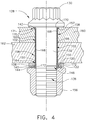
- Shaft 132 of the bolt member 128 extends through opening 148 of other washer 144 with washer 108 positioned between other washer 144 and head 130 of bolt member 128. In this configuration and alignment, at least a portion of other washer 144 aligns with a wall 150 of the sleeve 102, as seen in FIGS. 2 and 4 .
- Body 146 of other washer 144 defines flat opposing annular surfaces 152 an 154 surrounding opening 148 of other washer 144. Outside diameter of other washer 144 is greater than the diameter of recess 122 of the washer 108, as can be seen in FIGS 2 and 4 . Thus, in this embodiment, other washer 144 is in alignment with wall 150 of sleeve 102 and extends over recess 122 with other washer 144 in overlying relationship with washer 108, as seen in FIG. 4 .
- Nut 156 which defines threads (not shown) compatible to the threads defined by shaft 132 of the bolt member 128. As seen in FIGS 2 and 4 , other washer 144 is positioned between washer 108 and nut 156 wherein the threads of nut 156 and bolt member 128 are compatible so as to engage one another.
- Hole 158 is defined by at least two components or elements 160 and 162 that are to be joined together.
- elements 160 and 162 can be constructed of a variety of materials such as metal and/or composite material. These elements can vary in number and in the grip length or stack height.
- Hole 158 is either positioned in components 160 and 162 by way of drilling, reaming or any other common process employed to provide holes through components.
- Hole 158 extends through the at least two elements 160 and 162, such that a first end 140 of the first end portion 104 of sleeve 102 is positioned outside of a second end 164 of hole 158.
- a sleeve 102 with an outside diameter that is slightly smaller than the diameter of hole 158 and a length that is in excess of the length of hole 158.
- washer 108 is positioned about sleeve 102 with recess 122 facing first end 140 of sleeve 102 such that first end 140 of sleeve 102 extends through opening 120 and recess 122 and is positioned outside and beyond recess 122, as shown in FIG. 3 .
- Bolt member 128 is positioned to extend through sleeve 102 such that with second end 142 of sleeve 102 abutting head 130 at least a portion of a portion 136 which defines threads for shaft 132, as seen in FIGS. 3 and 4 extend beyond first end 140 of sleeve 102 and as seen in FIG. 3 , extends beyond washer 108.
- Nut 156 is then tightened onto bolt member 128 such other washer 144 engages first end 140 of wall 150 of sleeve 102 and head 130 of bolt member 128 engages a second end 142 of wall 150 of sleeve 102 causing a compressive force to be exerted onto sleeve 102.
- This compressive force causes outside surface 166 of sleeve 102 to exert a force against an interior wall 168 of hole158 resulting in electrical conductive contacts being made with components 160 and 162. Further tightening of nut 156 continues the application of compressive force onto sleeve 102 so as to cause a portion 170 of the second end portion 106 of sleeve 102 to deform against head 130 of bolt member 128.
- Portion 170 occupies a chamfered section 171 defined in component 160 and positioned about hole 158 and adjacent first end 157 of hole 158, as seen in FIG. 4 .
- This compressive force is similarly exerted on first end 140 of first end portion 104 of sleeve 102 in contact with other washer 144 causing at least a portion 172 of the first end portion 104 to deform At least a portion of deformed portion 172 of the first end portion 104 of sleeve 102 enters into the recess 122 of the washer 108.
- the interference fit of fastener assembly 100 is implemented by compressive forces being applied to sleeve 102 causing an electrical contact being made with the interior wall 168 of hole 158 which comprises components 160 and 162 being joined together. Compressive force is continued to be applied by further tightening nut 156 until end portions 104 and 106 deform.
- This configuration permits the user to be able to use standardized bolt members and corresponding nuts since sleeve 102 is being compressed and not laterally expanded by a bolt member as in the prior art.
- fastener assembly 100 a greater tolerance with respect to the length of sleeve 102 is permitted with fastener assembly 100 since recess 122 of washer 108 has the capacity to take in a portion of first end portion 104 in the process of securing the fastener assembly 100.
- This greater tolerance for the length of sleeve 102 also reduces the dependency on washers to be used in taking up excess length of sleeve 102.
- the fastener diameter will influence the diameter of the hole to be drilled or reamed in contrast to the prior art wherein the grip length influenced the diameter of the hole.
- fastener assembly 100 reduces the number varied sized holes to be drilled or reamed for fastening components together.
Landscapes
- Engineering & Computer Science (AREA)
- General Engineering & Computer Science (AREA)
- Mechanical Engineering (AREA)
- Aviation & Aerospace Engineering (AREA)
- Connection Of Plates (AREA)
- Dowels (AREA)
- Bolts, Nuts, And Washers (AREA)
Applications Claiming Priority (2)
| Application Number | Priority Date | Filing Date | Title |
|---|---|---|---|
| US14/454,161 US9714676B2 (en) | 2014-08-07 | 2014-08-07 | Hole-filling sleeve and washer design for bolt installation |
| PCT/US2015/027708 WO2016022184A1 (en) | 2014-08-07 | 2015-04-27 | Hole-filling sleeve and washer design for bolt installation |
Publications (2)
| Publication Number | Publication Date |
|---|---|
| EP3177530A1 EP3177530A1 (en) | 2017-06-14 |
| EP3177530B1 true EP3177530B1 (en) | 2019-04-10 |
Family
ID=53177884
Family Applications (1)
| Application Number | Title | Priority Date | Filing Date |
|---|---|---|---|
| EP15722621.8A Active EP3177530B1 (en) | 2014-08-07 | 2015-04-27 | Hole-filling sleeve and washer design for bolt installation |
Country Status (8)
| Country | Link |
|---|---|
| US (1) | US9714676B2 (enExample) |
| EP (1) | EP3177530B1 (enExample) |
| JP (1) | JP6571164B2 (enExample) |
| CN (1) | CN106795902B (enExample) |
| AU (1) | AU2015298754B2 (enExample) |
| CA (1) | CA2946992C (enExample) |
| ES (1) | ES2730750T3 (enExample) |
| WO (1) | WO2016022184A1 (enExample) |
Families Citing this family (13)
| Publication number | Priority date | Publication date | Assignee | Title |
|---|---|---|---|---|
| US9551373B2 (en) | 2014-06-27 | 2017-01-24 | The Boeing Company | Apparatus for fuel tank spark containment |
| EP3491257B1 (en) * | 2016-08-01 | 2023-03-29 | Coskun, Kenan | A connection system |
| US10894570B2 (en) * | 2017-05-04 | 2021-01-19 | Caterpillar Inc. | Pin retention design for a track chain |
| US20180339788A1 (en) * | 2017-05-26 | 2018-11-29 | Joe A. Garcia | Protective cap and nut gauge for an aircraft fuel tank fastener system |
| US10919588B2 (en) * | 2018-02-23 | 2021-02-16 | Caterpillar Inc. | Track pin and bushing retention design for a track chain |
| US10982704B2 (en) * | 2019-01-03 | 2021-04-20 | The Boeing Company | EME protection cap system with screw sealant mechanism |
| US11181137B2 (en) * | 2019-05-20 | 2021-11-23 | The Boeing Company | Fastener systems and assemblies for coupling a part to a composite structure, and related methods |
| US11946500B2 (en) * | 2019-08-07 | 2024-04-02 | Loose Wheel Sensors Inc. | Compression contact to monitor fastener elongation and grip force |
| WO2021239220A1 (en) * | 2020-05-27 | 2021-12-02 | Volvo Truck Corporation | A fastening element and a vehicle arrangement |
| KR102266423B1 (ko) * | 2020-12-21 | 2021-06-18 | 주식회사 대우볼트 | 원 웨이 파스너 |
| US20230083921A1 (en) * | 2021-09-10 | 2023-03-16 | The Boeing Company | Blind fasteners and associated methods for installing blind fasteners |
| WO2025093741A1 (en) * | 2023-11-02 | 2025-05-08 | Volvo Car Corporation | Cylindrical sleeve with extra features for alignment |
| EP4660467A1 (en) * | 2024-06-05 | 2025-12-10 | Volvo Car Corporation | Bolt sleeve with extra guiding feature of serration sleeves on screws |
Family Cites Families (26)
| Publication number | Priority date | Publication date | Assignee | Title |
|---|---|---|---|---|
| FR1226676A (fr) | 1959-02-27 | 1960-07-15 | Rondelle d'étanchéité | |
| US3568311A (en) * | 1968-09-30 | 1971-03-09 | Gen Electric | Insulating and spacing electrically conductive members |
| US3641865A (en) | 1970-04-20 | 1972-02-15 | Blake Rivet Co | Sealing shear fastener |
| US3835615A (en) | 1970-04-30 | 1974-09-17 | J King | Fastener joint construction |
| GB1524866A (en) * | 1974-10-17 | 1978-09-13 | Salter L | Fastener for multi metal stacks |
| GB1478462A (en) | 1974-11-06 | 1977-06-29 | Gkn Bolts Nuts Ltd | Captive washer for fastener assembly |
| US4435112A (en) * | 1981-04-09 | 1984-03-06 | Buell Industries, Inc. | Fastener assembly |
| US4518282A (en) * | 1981-08-27 | 1985-05-21 | Republic Corporation | Mine roof bearing plate with embossed area having conical and cylindrical sections |
| US4867461A (en) * | 1988-03-01 | 1989-09-19 | J. L. French Corporation | Gasket sealing system |
| US4975008A (en) * | 1989-03-31 | 1990-12-04 | Illinois Tool Works, Inc. | Fastener assembly with sealing grommet |
| US5603592A (en) * | 1994-10-03 | 1997-02-18 | Huck International, Inc. | High strength blind bolt with uniform high clamp over an extended grip range |
| US5682678A (en) * | 1995-11-13 | 1997-11-04 | The Nordam Group, Inc. | Mechanical repair for a honeycomb panel |
| JP3490927B2 (ja) * | 1999-05-19 | 2004-01-26 | ニチアス株式会社 | 熱遮蔽板に振動フローティングワッシャを取付ける方法 |
| JP2003094969A (ja) * | 2001-09-27 | 2003-04-03 | Showa Corp | プロペラシャフトのブラケット取付構造 |
| GB2403992B (en) | 2003-07-16 | 2006-10-11 | Newfrey Llc | Three part blind fastener |
| WO2008046439A1 (de) * | 2006-10-19 | 2008-04-24 | Elringklinger Ag | Hülse |
| DE102007026733A1 (de) | 2007-06-06 | 2008-12-11 | Harald Zahn Gmbh | Kopfplatte |
| US7874777B1 (en) * | 2007-07-16 | 2011-01-25 | The Grigoleit Company | Tapered sleeve, bolt, nut and washer device |
| JP2009063085A (ja) * | 2007-09-06 | 2009-03-26 | Shimizu Corp | 支圧ボルト接合方法および支圧ボルト接合用の支圧部材 |
| US8382413B2 (en) | 2008-11-17 | 2013-02-26 | The Boeing Company | Conductive sleeved fastener assembly |
| KR101420155B1 (ko) | 2009-10-22 | 2014-07-16 | 알코아 인코포레이티드 | 전도도가 향상된 슬리브형 파스너 및 그 제조 방법 |
| JP2011131822A (ja) * | 2009-12-25 | 2011-07-07 | Showa Corp | プロペラシャフトの支持構造 |
| US8791375B2 (en) * | 2010-12-16 | 2014-07-29 | The Boeing Company | Electrically conductive bushing connection to structure for current path |
| US8932022B2 (en) * | 2012-02-03 | 2015-01-13 | Pratt & Whitney Canada Corp. | Fastening system for fan and shaft interconnection |
| US8987612B2 (en) * | 2012-11-26 | 2015-03-24 | The Boeing Company | Bushings, apparatuses including bushings, and associated methods |
| US9551373B2 (en) * | 2014-06-27 | 2017-01-24 | The Boeing Company | Apparatus for fuel tank spark containment |
-
2014
- 2014-08-07 US US14/454,161 patent/US9714676B2/en active Active
-
2015
- 2015-04-27 JP JP2017506698A patent/JP6571164B2/ja active Active
- 2015-04-27 WO PCT/US2015/027708 patent/WO2016022184A1/en not_active Ceased
- 2015-04-27 CA CA2946992A patent/CA2946992C/en active Active
- 2015-04-27 ES ES15722621T patent/ES2730750T3/es active Active
- 2015-04-27 CN CN201580035801.4A patent/CN106795902B/zh active Active
- 2015-04-27 EP EP15722621.8A patent/EP3177530B1/en active Active
- 2015-04-27 AU AU2015298754A patent/AU2015298754B2/en active Active
Non-Patent Citations (1)
| Title |
|---|
| None * |
Also Published As
| Publication number | Publication date |
|---|---|
| EP3177530A1 (en) | 2017-06-14 |
| CA2946992C (en) | 2020-10-27 |
| US9714676B2 (en) | 2017-07-25 |
| JP2017528660A (ja) | 2017-09-28 |
| CN106795902B (zh) | 2019-08-30 |
| WO2016022184A1 (en) | 2016-02-11 |
| ES2730750T3 (es) | 2019-11-12 |
| JP6571164B2 (ja) | 2019-09-04 |
| CA2946992A1 (en) | 2016-02-11 |
| CN106795902A (zh) | 2017-05-31 |
| AU2015298754A1 (en) | 2016-11-03 |
| AU2015298754B2 (en) | 2018-07-19 |
| US20160040709A1 (en) | 2016-02-11 |
Similar Documents
| Publication | Publication Date | Title |
|---|---|---|
| EP3177530B1 (en) | Hole-filling sleeve and washer design for bolt installation | |
| EP2805889B1 (en) | Nut, washer & fastener head for electromagnetic effect protection | |
| EP2951095B1 (en) | Sleeved fastener assembly | |
| US7695226B2 (en) | High performance sleeved interference fasteners for composite applications | |
| CN105008225B (zh) | 具有电磁效应保护的紧固件系统及其安装方法 | |
| EP2473747B1 (en) | Blind rivet | |
| US20170082125A1 (en) | Robust adjustable panel insert | |
| RU2653043C2 (ru) | Втулки, устройства с использованием втулок и связанные с ними способы изготовления | |
| US5219255A (en) | Mechanically locked nut assembly | |
| TWI875741B (zh) | 使用具有縱向溝槽的可變形套筒之螺栓結合體 | |
| TW201920839A (zh) | 具有壓縮套之插入式緊固件 | |
| WO2014150253A1 (en) | Grounding sleeve | |
| GB2298156A (en) | Fastener for securing panels | |
| US20250122900A1 (en) | Nut retaining device and related methods | |
| CN114483744A (zh) | 单面紧固件、组件、燃料箱以及飞行器 |
Legal Events
| Date | Code | Title | Description |
|---|---|---|---|
| STAA | Information on the status of an ep patent application or granted ep patent |
Free format text: STATUS: THE INTERNATIONAL PUBLICATION HAS BEEN MADE |
|
| PUAI | Public reference made under article 153(3) epc to a published international application that has entered the european phase |
Free format text: ORIGINAL CODE: 0009012 |
|
| STAA | Information on the status of an ep patent application or granted ep patent |
Free format text: STATUS: REQUEST FOR EXAMINATION WAS MADE |
|
| 17P | Request for examination filed |
Effective date: 20161020 |
|
| AK | Designated contracting states |
Kind code of ref document: A1 Designated state(s): AL AT BE BG CH CY CZ DE DK EE ES FI FR GB GR HR HU IE IS IT LI LT LU LV MC MK MT NL NO PL PT RO RS SE SI SK SM TR |
|
| AX | Request for extension of the european patent |
Extension state: BA ME |
|
| DAV | Request for validation of the european patent (deleted) | ||
| DAX | Request for extension of the european patent (deleted) | ||
| STAA | Information on the status of an ep patent application or granted ep patent |
Free format text: STATUS: EXAMINATION IS IN PROGRESS |
|
| 17Q | First examination report despatched |
Effective date: 20180205 |
|
| GRAP | Despatch of communication of intention to grant a patent |
Free format text: ORIGINAL CODE: EPIDOSNIGR1 |
|
| STAA | Information on the status of an ep patent application or granted ep patent |
Free format text: STATUS: GRANT OF PATENT IS INTENDED |
|
| INTG | Intention to grant announced |
Effective date: 20180920 |
|
| GRAS | Grant fee paid |
Free format text: ORIGINAL CODE: EPIDOSNIGR3 |
|
| GRAJ | Information related to disapproval of communication of intention to grant by the applicant or resumption of examination proceedings by the epo deleted |
Free format text: ORIGINAL CODE: EPIDOSDIGR1 |
|
| GRAL | Information related to payment of fee for publishing/printing deleted |
Free format text: ORIGINAL CODE: EPIDOSDIGR3 |
|
| STAA | Information on the status of an ep patent application or granted ep patent |
Free format text: STATUS: EXAMINATION IS IN PROGRESS |
|
| GRAP | Despatch of communication of intention to grant a patent |
Free format text: ORIGINAL CODE: EPIDOSNIGR1 |
|
| STAA | Information on the status of an ep patent application or granted ep patent |
Free format text: STATUS: GRANT OF PATENT IS INTENDED |
|
| INTC | Intention to grant announced (deleted) | ||
| INTG | Intention to grant announced |
Effective date: 20190206 |
|
| GRAA | (expected) grant |
Free format text: ORIGINAL CODE: 0009210 |
|
| STAA | Information on the status of an ep patent application or granted ep patent |
Free format text: STATUS: THE PATENT HAS BEEN GRANTED |
|
| AK | Designated contracting states |
Kind code of ref document: B1 Designated state(s): AL AT BE BG CH CY CZ DE DK EE ES FI FR GB GR HR HU IE IS IT LI LT LU LV MC MK MT NL NO PL PT RO RS SE SI SK SM TR |
|
| REG | Reference to a national code |
Ref country code: GB Ref legal event code: FG4D |
|
| REG | Reference to a national code |
Ref country code: CH Ref legal event code: EP Ref country code: AT Ref legal event code: REF Ref document number: 1118327 Country of ref document: AT Kind code of ref document: T Effective date: 20190415 |
|
| REG | Reference to a national code |
Ref country code: IE Ref legal event code: FG4D |
|
| REG | Reference to a national code |
Ref country code: DE Ref legal event code: R096 Ref document number: 602015028002 Country of ref document: DE |
|
| REG | Reference to a national code |
Ref country code: NL Ref legal event code: MP Effective date: 20190410 |
|
| REG | Reference to a national code |
Ref country code: LT Ref legal event code: MG4D |
|
| REG | Reference to a national code |
Ref country code: AT Ref legal event code: MK05 Ref document number: 1118327 Country of ref document: AT Kind code of ref document: T Effective date: 20190410 |
|
| PG25 | Lapsed in a contracting state [announced via postgrant information from national office to epo] |
Ref country code: NL Free format text: LAPSE BECAUSE OF FAILURE TO SUBMIT A TRANSLATION OF THE DESCRIPTION OR TO PAY THE FEE WITHIN THE PRESCRIBED TIME-LIMIT Effective date: 20190410 |
|
| PG25 | Lapsed in a contracting state [announced via postgrant information from national office to epo] |
Ref country code: HR Free format text: LAPSE BECAUSE OF FAILURE TO SUBMIT A TRANSLATION OF THE DESCRIPTION OR TO PAY THE FEE WITHIN THE PRESCRIBED TIME-LIMIT Effective date: 20190410 Ref country code: PT Free format text: LAPSE BECAUSE OF FAILURE TO SUBMIT A TRANSLATION OF THE DESCRIPTION OR TO PAY THE FEE WITHIN THE PRESCRIBED TIME-LIMIT Effective date: 20190910 Ref country code: LT Free format text: LAPSE BECAUSE OF FAILURE TO SUBMIT A TRANSLATION OF THE DESCRIPTION OR TO PAY THE FEE WITHIN THE PRESCRIBED TIME-LIMIT Effective date: 20190410 Ref country code: FI Free format text: LAPSE BECAUSE OF FAILURE TO SUBMIT A TRANSLATION OF THE DESCRIPTION OR TO PAY THE FEE WITHIN THE PRESCRIBED TIME-LIMIT Effective date: 20190410 Ref country code: AL Free format text: LAPSE BECAUSE OF FAILURE TO SUBMIT A TRANSLATION OF THE DESCRIPTION OR TO PAY THE FEE WITHIN THE PRESCRIBED TIME-LIMIT Effective date: 20190410 Ref country code: NO Free format text: LAPSE BECAUSE OF FAILURE TO SUBMIT A TRANSLATION OF THE DESCRIPTION OR TO PAY THE FEE WITHIN THE PRESCRIBED TIME-LIMIT Effective date: 20190710 Ref country code: SE Free format text: LAPSE BECAUSE OF FAILURE TO SUBMIT A TRANSLATION OF THE DESCRIPTION OR TO PAY THE FEE WITHIN THE PRESCRIBED TIME-LIMIT Effective date: 20190410 |
|
| REG | Reference to a national code |
Ref country code: ES Ref legal event code: FG2A Ref document number: 2730750 Country of ref document: ES Kind code of ref document: T3 Effective date: 20191112 |
|
| PG25 | Lapsed in a contracting state [announced via postgrant information from national office to epo] |
Ref country code: LV Free format text: LAPSE BECAUSE OF FAILURE TO SUBMIT A TRANSLATION OF THE DESCRIPTION OR TO PAY THE FEE WITHIN THE PRESCRIBED TIME-LIMIT Effective date: 20190410 Ref country code: GR Free format text: LAPSE BECAUSE OF FAILURE TO SUBMIT A TRANSLATION OF THE DESCRIPTION OR TO PAY THE FEE WITHIN THE PRESCRIBED TIME-LIMIT Effective date: 20190711 Ref country code: PL Free format text: LAPSE BECAUSE OF FAILURE TO SUBMIT A TRANSLATION OF THE DESCRIPTION OR TO PAY THE FEE WITHIN THE PRESCRIBED TIME-LIMIT Effective date: 20190410 Ref country code: BG Free format text: LAPSE BECAUSE OF FAILURE TO SUBMIT A TRANSLATION OF THE DESCRIPTION OR TO PAY THE FEE WITHIN THE PRESCRIBED TIME-LIMIT Effective date: 20190710 Ref country code: RS Free format text: LAPSE BECAUSE OF FAILURE TO SUBMIT A TRANSLATION OF THE DESCRIPTION OR TO PAY THE FEE WITHIN THE PRESCRIBED TIME-LIMIT Effective date: 20190410 |
|
| REG | Reference to a national code |
Ref country code: CH Ref legal event code: PL |
|
| REG | Reference to a national code |
Ref country code: BE Ref legal event code: MM Effective date: 20190430 |
|
| PG25 | Lapsed in a contracting state [announced via postgrant information from national office to epo] |
Ref country code: AT Free format text: LAPSE BECAUSE OF FAILURE TO SUBMIT A TRANSLATION OF THE DESCRIPTION OR TO PAY THE FEE WITHIN THE PRESCRIBED TIME-LIMIT Effective date: 20190410 Ref country code: LU Free format text: LAPSE BECAUSE OF NON-PAYMENT OF DUE FEES Effective date: 20190427 Ref country code: IS Free format text: LAPSE BECAUSE OF FAILURE TO SUBMIT A TRANSLATION OF THE DESCRIPTION OR TO PAY THE FEE WITHIN THE PRESCRIBED TIME-LIMIT Effective date: 20190810 |
|
| REG | Reference to a national code |
Ref country code: DE Ref legal event code: R097 Ref document number: 602015028002 Country of ref document: DE |
|
| PG25 | Lapsed in a contracting state [announced via postgrant information from national office to epo] |
Ref country code: MC Free format text: LAPSE BECAUSE OF FAILURE TO SUBMIT A TRANSLATION OF THE DESCRIPTION OR TO PAY THE FEE WITHIN THE PRESCRIBED TIME-LIMIT Effective date: 20190410 Ref country code: RO Free format text: LAPSE BECAUSE OF FAILURE TO SUBMIT A TRANSLATION OF THE DESCRIPTION OR TO PAY THE FEE WITHIN THE PRESCRIBED TIME-LIMIT Effective date: 20190410 Ref country code: CZ Free format text: LAPSE BECAUSE OF FAILURE TO SUBMIT A TRANSLATION OF THE DESCRIPTION OR TO PAY THE FEE WITHIN THE PRESCRIBED TIME-LIMIT Effective date: 20190410 Ref country code: LI Free format text: LAPSE BECAUSE OF NON-PAYMENT OF DUE FEES Effective date: 20190430 Ref country code: CH Free format text: LAPSE BECAUSE OF NON-PAYMENT OF DUE FEES Effective date: 20190430 Ref country code: EE Free format text: LAPSE BECAUSE OF FAILURE TO SUBMIT A TRANSLATION OF THE DESCRIPTION OR TO PAY THE FEE WITHIN THE PRESCRIBED TIME-LIMIT Effective date: 20190410 Ref country code: SK Free format text: LAPSE BECAUSE OF FAILURE TO SUBMIT A TRANSLATION OF THE DESCRIPTION OR TO PAY THE FEE WITHIN THE PRESCRIBED TIME-LIMIT Effective date: 20190410 Ref country code: DK Free format text: LAPSE BECAUSE OF FAILURE TO SUBMIT A TRANSLATION OF THE DESCRIPTION OR TO PAY THE FEE WITHIN THE PRESCRIBED TIME-LIMIT Effective date: 20190410 |
|
| PLBE | No opposition filed within time limit |
Free format text: ORIGINAL CODE: 0009261 |
|
| STAA | Information on the status of an ep patent application or granted ep patent |
Free format text: STATUS: NO OPPOSITION FILED WITHIN TIME LIMIT |
|
| PG25 | Lapsed in a contracting state [announced via postgrant information from national office to epo] |
Ref country code: SM Free format text: LAPSE BECAUSE OF FAILURE TO SUBMIT A TRANSLATION OF THE DESCRIPTION OR TO PAY THE FEE WITHIN THE PRESCRIBED TIME-LIMIT Effective date: 20190410 Ref country code: BE Free format text: LAPSE BECAUSE OF NON-PAYMENT OF DUE FEES Effective date: 20190430 |
|
| 26N | No opposition filed |
Effective date: 20200113 |
|
| PG25 | Lapsed in a contracting state [announced via postgrant information from national office to epo] |
Ref country code: TR Free format text: LAPSE BECAUSE OF FAILURE TO SUBMIT A TRANSLATION OF THE DESCRIPTION OR TO PAY THE FEE WITHIN THE PRESCRIBED TIME-LIMIT Effective date: 20190410 |
|
| PG25 | Lapsed in a contracting state [announced via postgrant information from national office to epo] |
Ref country code: IE Free format text: LAPSE BECAUSE OF NON-PAYMENT OF DUE FEES Effective date: 20190427 |
|
| PG25 | Lapsed in a contracting state [announced via postgrant information from national office to epo] |
Ref country code: SI Free format text: LAPSE BECAUSE OF FAILURE TO SUBMIT A TRANSLATION OF THE DESCRIPTION OR TO PAY THE FEE WITHIN THE PRESCRIBED TIME-LIMIT Effective date: 20190410 |
|
| PG25 | Lapsed in a contracting state [announced via postgrant information from national office to epo] |
Ref country code: CY Free format text: LAPSE BECAUSE OF FAILURE TO SUBMIT A TRANSLATION OF THE DESCRIPTION OR TO PAY THE FEE WITHIN THE PRESCRIBED TIME-LIMIT Effective date: 20190410 |
|
| PG25 | Lapsed in a contracting state [announced via postgrant information from national office to epo] |
Ref country code: MT Free format text: LAPSE BECAUSE OF FAILURE TO SUBMIT A TRANSLATION OF THE DESCRIPTION OR TO PAY THE FEE WITHIN THE PRESCRIBED TIME-LIMIT Effective date: 20190410 Ref country code: HU Free format text: LAPSE BECAUSE OF FAILURE TO SUBMIT A TRANSLATION OF THE DESCRIPTION OR TO PAY THE FEE WITHIN THE PRESCRIBED TIME-LIMIT; INVALID AB INITIO Effective date: 20150427 |
|
| PG25 | Lapsed in a contracting state [announced via postgrant information from national office to epo] |
Ref country code: MK Free format text: LAPSE BECAUSE OF FAILURE TO SUBMIT A TRANSLATION OF THE DESCRIPTION OR TO PAY THE FEE WITHIN THE PRESCRIBED TIME-LIMIT Effective date: 20190410 |
|
| P01 | Opt-out of the competence of the unified patent court (upc) registered |
Effective date: 20230516 |
|
| PGFP | Annual fee paid to national office [announced via postgrant information from national office to epo] |
Ref country code: DE Payment date: 20250429 Year of fee payment: 11 |
|
| PGFP | Annual fee paid to national office [announced via postgrant information from national office to epo] |
Ref country code: ES Payment date: 20250505 Year of fee payment: 11 Ref country code: GB Payment date: 20250428 Year of fee payment: 11 |
|
| PGFP | Annual fee paid to national office [announced via postgrant information from national office to epo] |
Ref country code: IT Payment date: 20250422 Year of fee payment: 11 |
|
| PGFP | Annual fee paid to national office [announced via postgrant information from national office to epo] |
Ref country code: FR Payment date: 20250425 Year of fee payment: 11 |