EP3177522B1 - Regler mit entfernbarem erststufenöffnungskörper - Google Patents
Regler mit entfernbarem erststufenöffnungskörper Download PDFInfo
- Publication number
- EP3177522B1 EP3177522B1 EP15829825.7A EP15829825A EP3177522B1 EP 3177522 B1 EP3177522 B1 EP 3177522B1 EP 15829825 A EP15829825 A EP 15829825A EP 3177522 B1 EP3177522 B1 EP 3177522B1
- Authority
- EP
- European Patent Office
- Prior art keywords
- inlet
- valve
- high pressure
- orifice
- valve body
- Prior art date
- Legal status (The legal status is an assumption and is not a legal conclusion. Google has not performed a legal analysis and makes no representation as to the accuracy of the status listed.)
- Active
Links
Images

Classifications
-
- B—PERFORMING OPERATIONS; TRANSPORTING
- B63—SHIPS OR OTHER WATERBORNE VESSELS; RELATED EQUIPMENT
- B63C—LAUNCHING, HAULING-OUT, OR DRY-DOCKING OF VESSELS; LIFE-SAVING IN WATER; EQUIPMENT FOR DWELLING OR WORKING UNDER WATER; MEANS FOR SALVAGING OR SEARCHING FOR UNDERWATER OBJECTS
- B63C11/00—Equipment for dwelling or working underwater; Means for searching for underwater objects
- B63C11/02—Divers' equipment
- B63C11/18—Air supply
- B63C11/22—Air supply carried by diver
- B63C11/2227—Second-stage regulators
-
- A—HUMAN NECESSITIES
- A62—LIFE-SAVING; FIRE-FIGHTING
- A62B—DEVICES, APPARATUS OR METHODS FOR LIFE-SAVING
- A62B9/00—Component parts for respiratory or breathing apparatus
- A62B9/02—Valves
- A62B9/022—Breathing demand regulators
-
- B—PERFORMING OPERATIONS; TRANSPORTING
- B63—SHIPS OR OTHER WATERBORNE VESSELS; RELATED EQUIPMENT
- B63C—LAUNCHING, HAULING-OUT, OR DRY-DOCKING OF VESSELS; LIFE-SAVING IN WATER; EQUIPMENT FOR DWELLING OR WORKING UNDER WATER; MEANS FOR SALVAGING OR SEARCHING FOR UNDERWATER OBJECTS
- B63C11/00—Equipment for dwelling or working underwater; Means for searching for underwater objects
- B63C11/02—Divers' equipment
- B63C11/18—Air supply
- B63C11/22—Air supply carried by diver
- B63C11/2209—First-stage regulators
-
- G—PHYSICS
- G05—CONTROLLING; REGULATING
- G05D—SYSTEMS FOR CONTROLLING OR REGULATING NON-ELECTRIC VARIABLES
- G05D16/00—Control of fluid pressure
- G05D16/04—Control of fluid pressure without auxiliary power
- G05D16/10—Control of fluid pressure without auxiliary power the sensing element being a piston or plunger
-
- G—PHYSICS
- G05—CONTROLLING; REGULATING
- G05D—SYSTEMS FOR CONTROLLING OR REGULATING NON-ELECTRIC VARIABLES
- G05D7/00—Control of flow
- G05D7/01—Control of flow without auxiliary power
-
- Y—GENERAL TAGGING OF NEW TECHNOLOGICAL DEVELOPMENTS; GENERAL TAGGING OF CROSS-SECTIONAL TECHNOLOGIES SPANNING OVER SEVERAL SECTIONS OF THE IPC; TECHNICAL SUBJECTS COVERED BY FORMER USPC CROSS-REFERENCE ART COLLECTIONS [XRACs] AND DIGESTS
- Y10—TECHNICAL SUBJECTS COVERED BY FORMER USPC
- Y10T—TECHNICAL SUBJECTS COVERED BY FORMER US CLASSIFICATION
- Y10T137/00—Fluid handling
- Y10T137/7722—Line condition change responsive valves
- Y10T137/7781—With separate connected fluid reactor surface
- Y10T137/7793—With opening bias [e.g., pressure regulator]
- Y10T137/7809—Reactor surface separated by apertured partition
- Y10T137/781—In valve stem
- Y10T137/7811—Also through reactor surface
Definitions
- This invention generally relates to a first stage regulatory valve for use in a self-contained underwater breathing apparatus.
- First stage pressure regulators for underwater breathing convert high pressure gas to a lower pressure at or near a pressure that can be breathed by a diver.
- the high pressure gas is generally supplied to the first stage pressure regulator from an outlet of a cylinder of compressed air at a pressure that may be in excess of 4,000 psi.
- the high pressure gas is received by the first stage pressure regulator through an orifice of the first stage pressure regulator into a high pressure chamber of the valve body of the first stage pressure regulator.
- Orifice sizes, hardness, and sealing surfaces contribute to the efficiency and amount of high pressure air passing into the high pressure chamber of the valve body.
- the high pressure gas has been received into the high pressure chamber of the valve body through an orifice formed into and of the valve body.
- Such high pressure receiving orifices that are integral with the valve body have resulted in complex and time consuming machining of the first stage pressure regulating valve body. Additionally, because the orifice is integral with the valve body the hardness of the outer sealing edges of the orifice is limited to the same material and hence the same hardness of the valve body itself. Accordingly, the sealing edge of the orifice has proven difficult to protect from wear. Further, it has been difficult to protect such an integral orifice from corrosion because its location within the valve body makes it difficult to coat with anti-corrosion materials. Still further, quality control of the integral valve body orifice must be done with the valve body itself as opposed to being able to do quality control of the orifice independent of the valve body. Moreover, maintenance of such orifices has proven difficult since its wear is wear of the valve body itself.
- the US patent US 3,211,175 discloses a valve regulator embodied in a self-contained air-breathing apparatus with a seat member slidably arranged in the lower portion of a vertical bore for regulating pressure.
- US patent application US 5,662,100 A is concerned with dynamic responsiveness of a pressure regulator including a body with a bore and a seat member being sealingly and slidably arranged within the lower portion of the bore for providing a valve seat.
- the present invention seeks to provide improvements over the current state of the art of first stage pressure regulators for underwater breathing devices.
- the invention provides a first stage pressure regulator comprising a valve body having an inlet and an outlet that define a pressure chamber between the inlet and an outlet.
- the valve body defines a pressure compensation chamber having an opening fluidly communicating the pressure compensation chamber with the surrounding water.
- the first stage pressure regulator comprises an inlet tubular union removably received into the inlet.
- a removable high pressure orifice body defines an orifice therethrough.
- the inlet tubular union is adapted to limit axial motion of the orifice body.
- the orifice body is carried by the valve body proximate the inlet.
- a valve seat is within the valve body.
- a valve member is slidably carried within the valve body pressure chamber.
- the valve member has a valve end.
- the valve seat is carried by the valve end.
- the valve member is slidable between an open state and a closed state. In the open state the valve end carrying the valve seat is spaced from the removable high pressure orifice permitting fluid flow through the orifice between the inlet and outlet. In the closed state the valve end carrying the valve seat is sealingly seated against the removable high pressure orifice body preventing fluid flow between the inlet and outlet.
- the removable high pressure orifice body may include an upstream end in the form of a T-shaped head having a larger diameter than a downstream end.
- the orifice body may extend downstream of the T-shaped head into the inlet.
- a bottom surface of the T-shaped head is seated upon an outward facing surface of the inlet of the valve body.
- a top surface of the T-shaped head is in contact with the inlet tubular union such that the tubular union secures the orifice body in the inlet.
- the T-shaped head may fit inside a cavity at a distal end of the inlet tubular union.
- the T-shaped head may include a slot that fluidly communicates a high pressure passage surrounding the T-shaped head with a center passage of the inlet tubular union.
- the high pressure passage is in fluid communication with a high pressure exit port of the valve body.
- a head of the removable high pressure orifice body is inside a cavity formed in a distal end of the inlet tubular union.
- a T-shaped head of the high pressure orifice body is dimensioned to fit within a cavity of the inlet tubular union.
- the orifice body is axially movable.
- an end of the removable high pressure orifice body is in sealing contact with the valve seat in the closed state.
- valve body comprises a material of a first hardness and the removable high pressure orifice is comprised of a material of a second hardness greater than the first hardness.
- the removable high pressure orifice body generally includes a T-shaped head at an upstream end; a conical protrusion at a downstream end; a slot formed into a top surface of the T-shaped head; an annular groove formed into the valve body proximate an axial center of the orifice body.
- the annular groove receives an O-ring; the O-ring is in sealing contact with walls of the inlet of the valve body.
- the conical protrusion terminates at a tip; the tip is in sealing contact with the valve seat in the closed state.
- the removable high pressure orifice is free of fastening threads.
- the compensation chamber includes an insulated bushing; an insulating ring an insulating sleeve and an insulating biasing member.
- the invention provides a method of assembly of a first stage pressure regulator.
- the method includes seating a removable high pressure orifice that defines an orifice in an inlet of a valve body.
- the method includes securing an inlet tubular union to the valve body to limit axial motion of the orifice body within the inlet between the inlet tubular union and the valve body.
- the valve body has an inlet and an outlet and that define a pressure chamber between the inlet and an outlet.
- the valve body defines a pressure compensation chamber having an opening fluidly communicating the pressure compensation chamber with the surrounding water.
- the valve body includes a valve seat within the valve body.
- a valve member is slidably carried within the valve body pressure chamber and has a valve end and an expansion head connected to the valve end.
- the valve member is slidable between an open state and a closed state. In the open state the valve end carrying the valve seat is spaced from a downstream end of the removable high pressure orifice permitting fluid flow between the inlet and outlet. In a closed state the valve end carrying the valve seat is sealingly seated against the downstream end of the removable high pressure orifice preventing fluid flow between the inlet and outlet.
- the expansion head is exposed to the pressure compensation chamber and is operably acted upon by the surrounding water within the pressure compensation chamber to bias the valve member toward the open state.
- a biasing member is carried within the compensation chamber to bias the valve member towards the open state.
- the removable high pressure orifice body of the method may include a T-shaped head at an upstream end, a conical protrusion at a downstream end, a slot formed into a top surface of the T-shaped head, a central passage through the valve body and an annular groove formed into the valve body at approximate a longitudinal center of the orifice body.
- the step of securing is threading.
- the step of securing includes receiving a head of the removable high pressure orifice body in a cavity in a distal end of the inlet tubular union.
- the invention provides a method of servicing a first stage pressure regulator.
- the method comprises removing a removable high pressure orifice body from an inlet of a valve body.
- the method includesmodifying the removable high pressure orifice body and includes the step of reinserting the repaired orifice body into and on the inlet of the valve body.
- the step of modifying the removable high pressure orifice body may include machining a new diameter of a flow restriction orifice of the removable high pressure orifice body that is of greater diameter than an original diameter of the flow restriction orifice.
- the step of securing fixes the orifice body within the inlet between the inlet tubular union and the valve body.
- the step of modifying may include replacing the removable high pressure orifice body with a second removable high pressure orifice body.
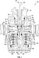
- FIG. 1 illustrates a first stage air pressure reduction valve 10 of a two stage system.
- the first stage air pressure reduction valve 10 may also be referred to as first stage pressure regulator 10 or even more simply as pressure regulator 10.
- the first stage pressure regulator 10 is used to reduce the pressure of high pressure gas stored, typically, in a tank carried by a diver to a more manageable pressure that is used by a second stage regulator that supplies breathing gas to the diver.
- the high pressure gas source approximates 4000 psi.
- the high pressure air is compressed air that may be a mixture of oxygen and other suitable gases for diving. For simplicity, hereinafter, the air or gas mixture will be referred to as gas.
- the pressure regulator 10 generally includes a valve body 12.
- the valve body 12 is generally a two piece valve body having two components 13 and 15 attached to one another.
- the components 13 and 15 are threadedly connected to one another.
- the valve body 12 may be constructed of brass and coated in an anti-corrosion material such as chrome.
- the valve body 12 is joined to a supply of compressed air (not shown), such as a cylinder of compressed air, by an inlet tubular union 14 attached to a high pressure inlet 16 of the valve body 12.
- the inlet tubular union 14 may be made of brass and coated in an anti-corrosion material such as chrome.
- the inlet tubular union 14 is threadedly connected to the high pressure inlet 16 of the valve body 12.
- the inlet tubular union 14 is a conduit having a center passage 18 surrounding a center axis 20 of the inlet tubular union 14. High pressure air flows from the cylinder through the center passage 18 and selectively into and through an orifice 22 of a removable high pressure orifice body 23.
- the center passage 18 of the inlet tubular union 14 has a central portion of a first diameter 26 and a downstream portion 32 that includes an annular cavity 44 having a second diameter 34 that is greater than first diameter 26 formed by a stepped portion of the inner surface of inlet tubular union 14.
- the center passage 18 may be coaxial and concentric with a center axis 36 of the orifice 22 of the removable high pressure orifice body 23.
- FIG. 2 illustrates an enlarged view of the downstream portion 32 of the inlet tubular union 14.
- the downstream portion 32 has an outermost surface 40 that forms a distal end of the tubular union 14 that may contact or simply come very near without contacting an axially outward facing surface 42 of the high pressure inlet 16 of the valve body 12.
- the annular cavity 44 is formed into the outermost surface 40 of the downstream portion 32 of the inlet tubular union 14.
- the annular cavity 44 is in the form of a cylindrical cavity having diameter 34 and having a smooth planer surface 46 and a sidewall 47 extending axially between surfaces 40 and 46.
- the depth 48 of the annular cavity 44 is defined as the distance from the surface 40 of the downstream portion 32 of the inlet tubular union 14 to the upstream surface 46 of the cavity 44 and corresponds to sidewall 47.
- the depth 48 of the cavity 44 may be configured to seat orifice body 23 against component 13 of the valve body 12 and thereby fix the orifice body 23 between the inlet tubular union 14 and the valve body 12.
- the cavity 44 is spaced upstream of surface 42 far enough to permits the orifice body 23 to move axially within the cavity 44 with surface 40 and 46 acting as stops to limit the axial movement of the orifice body 23.
- the depth 48 of the cavity 44 of the inlet tubular union is such that a T-shaped head 52 of the removable high pressure orifice body 23 is received into the cavity 44 and is sandwiched between the planar surface 46 of the cavity 44 of the inlet tubular union 14 and the valve body 12. More specifically, a top surface 55 ( FIG. 3 ) of the T-shaped head 52 may be in contact with the bottom surface 46 of the inlet tubular union 14 while the orifice body 23 is in axial contact with and thus seated upon valve body 12. A slot 53 ( FIG. 3 ) is formed into the top surface 55 of the T-shaped head 52.
- the slot 53 provides a means by which high pressure air in the center passage 18 of the inlet tubular union 14 fluidly communicates with a high pressure passage 116 when the planar surface 46 of the inlet tubular union is in contact with the top surface 55 of the T-shaped head 52.
- the fluid communication is possible because the diameter 120 of the T-shaped head is less than the diameter 34 of the cavity 44 and thus an annular high pressure passage 116 is formed that surrounds the T-shaped head and fluidly communicates with a high pressure exit port 118 of the valve body 12.
- the high pressure exit port 118 may permit a high pressure gauge to attach to the valve body 12 via the exit port 118 to enable a diver to read the pressure of the tank (not shown) containing the high pressure air.
- planar surface 46 of the cavity is not in contact with the top surface 55 of the T-shaped head and thus the orifice body 23 is free to move in an axial direction and is thus held in place against the valve body by the high pressure air in contact with the top surface 55 of the T-shaped head.
- the axial movement of the orifice body 23 is not without limits, that is, the planar surface 46 acts as a stop for limiting the axial movement of the orifice body 23.
- it is the high pressure gas acting against the orifice body 23 that seats the orifice body 23 against the valve body 12.
- a gap 122 is created between planar surface 46 and top surface 55.
- the gap 122 is in fluid communication with the annular high pressure passage 116 which in turn, as previously discussed is in fluid communication with the high pressure exit port 118 of the valve body 12.
- the inlet tubular union 14 may be threadily received into the high pressure inlet 16 of the valve body 12 and over the top surface 55 of the T-shaped head 52. Although, threading is shown, it is not the intent to limit reception by threading as other fastening means may be used. Thus, it can be readily appreciated that insertion of the removable high pressure orifice body 23 takes place prior to threading the inlet tubular union 14 into the high pressure inlet 16 of the valve body 12. The fastening of the inlet tubular union 14 to the high pressure inlet 16 of the valve body 12 easily secures the removable high pressure orifice body 23 between the inlet tubular union 16 and the valve body 12 during assembly.
- the T-shaped head 52 of the high pressure orifice body 23 is received into the cavity 44 of the inlet tubular union 14 as the inlet tubular union 14 is threaded, as shown in this embodiment, into the high pressure inlet 16 of the valve body 12. Further, during disassembly of the regulator 10 one need only to unthread the inlet tubular union 14 from the high pressure inlet 16 of the valve body 12 in order to access the removable high pressure orifice 22. Once the inlet tubular union 14 is removed from the inlet 16, the removable high pressure orifice body 23 can be easily removed from the inlet 16. The removal may be done, for example, by a simple grasp and light pull of the T-shaped head 52 and/or simply allowing gravity to let the removable high pressure orifice body 23 to fall from the inlet 16.
- the removable high pressure orifice body 23 provides for less complex machining processes with respect to forming the valve body 12 (or the inlet tubular union 14).
- a high pressure orifice was machined as part of the valve body 12 (or inlet tubular union 14). Such machining can be readily understood to be more complex and time consuming than a valve body 12 (or inlet tubular union 14) that does not have an integral high pressure orifice.
- an embodiment of the removable high pressure orifice 22 may provide for a removable high pressure orifice body 23 made of a material of a first hardness while the valve body 12 may be made of material of a second hardness.
- the first hardness may be greater than the second hardness.
- the high pressure orifice 22 may be made of stainless steel while the valve body 12 may be made of nickel-brass. Because the removable high pressure orifice body 23 may be of a greater hardness than the valve body 12, sealing edges 28 of the removable high pressure orifice body 23 will wear more slowly than mating surfaces of the valve body 12.
- the removable high pressure orifice body 23 defines orifice 22 that receives high pressure air from the center passage 18 of the inlet tubular union 14.
- the central orifice 22 of the removable high pressure orifice body 23 has a diameter 74 that is less than the diameter 26 of the center passage 18 of the inlet tubular 14 and thus acts as a flow restriction.
- the diameter 74 of the orifice 22 of the removable high pressure orifice body 23 may be between 1 and 4 mm. In a preferred embodiment the diameter of the orifice may be between 1.5 mm and 3 mm and in a more preferred embodiment the diameter 74 may be between 1.9 mm and 2.1 mm.
- the replaceable high pressure orifice body 23 as heretofore described has shown the unexpected result of as much as 15% increased airflow through the pressure regulator valve 10 as compared to similar pressure regulator valves having a high pressure orifice integral with the valve body 12.
- valve body 12 and the inlet tubular union 14 can more easily be protected from corrosion.
- the high pressure inlet 16 of the valve body 12 and the inner surface of the inlet tubular union 14 are smooth as opposed to inner surfaces having threads or other internal grooves. This presents an advantage because smooth continuous surfaces are more easily protected from corrosion with anti-corrosion coatings than are those with threads or grooves that are difficult to coat.
- the removable high pressure orifice body 23 as was discussed above, has a T-shaped head 52 having a slot 53 at an upstream end 56.
- the T-shaped head 52 provides the means by which the removable high pressure orifice body 23 mates with the valve body 12 and is received into the cavity 44 of the inlet tubular union 14. (See FIGS. 1 and 2 )
- An annular groove 68 is provided in approximately the axial center of removable high pressure orifice body 23.
- Axial is to be understood in this context as between the upstream end 56 of the removable high pressure orifice body 23 and the downstream end 58 of the removable high pressure orifice body 23 and corresponds to central axis 36.
- the annular groove 68 provides sealing and bearing surfaces 70 for the annular radial seal 54 carried therein.
- the annular radial seal 54 also bears against and seals with an annular interior wall 72 ( FIG. 2 ) of the high pressure inlet 16 of the valve body 12 so as to prevent any gas or liquid from bypassing orifice 22.
- the valve body 12 provides a pressure chamber 76 and a compensation chamber 78.
- the pressure chamber 76 and compensation chamber 78 may be concentric and coaxial.
- the pressure chamber 76 and compensation chamber 78 are separated from one another by a partition wall 80 and a valve member 82 that is movable.
- the pressure chamber 76 communicates via the inlet tubular union 14 and orifice 22 of the removable high pressure orifice body 23 with the pressurized gas supplied into the pressure regulator 10 from the cylinder of compressed gas.
- the compensation chamber 78 communicates with the outside ambient water through openings 84 in the valve body 12. During a dive, the compensation chamber 78 fills with water at a pressure corresponding to the dive depth.
- the valve member 82 is slidingly carried within the valve body 12.
- the valve member 82 has an expansion head 86 that is connected to a valve end 88 by a tubular stem 90.
- the tubular stem 90 and expansion head 86 are both sealed to the valve body 12 to prevent ingress of ambient water or egress of the gas within the regulator.
- the tubular stem 90 and expansion head 86 are also allowed to slide axially within the valve body 12 as illustrated by arrow 92 so as to allow the pressure regulator 10 to reduce the pressure of the gas from its inlet pressure.
- the tubular stem 90 is preferably a metal material such as stainless steel to ensure a better resistance both mechanically and chemically (saline, etc.).
- the tubular stem 90 defines the valve end 88.
- the valve end 88 is shaped to carry valve seat 66.
- the valve end 88 carrying valve seat 66 selectively seats against the distal end of the tapered protrusion 64 of the removable high pressure orifice body 23.
- the pressure regulator 10 is in an open state and gas is allowed to flow through the orifice 22 to outlet 94 of the valve body 12 and into the tubular stem 90 through passage 83.
- This configuration is illustrated in FIG. 1 .
- the valve end 88 is biased against the distal end of the tapered protrusion 64, the fluid flow path from the inlet tubular union 14 through the orifice 23 of the removable high pressure orifice body 23 is closed preventing fluid flow.
- the valve seat 66 is preferably of a non-metallic material so as to provide a good sealing engagement with the valve end 88 and the distal end of the tapered protrusion 64 of the removable high pressure orifice body 23 when the valve member 22 is in a closed state.
- the expansion head 86 is at an end opposite valve end 88 of the valve member 82 and has an enlarged conical shape. Gas passes from the pressure chamber 76 into passage 83, through the tubular stem 90 and into the enlarged area provided by the conical shape of the expansion head 86. This conical shape provides an enlarged area in which the gas is allowed to expand.
- the exterior surfaces of the expansion head are acted on by the water within the compensation chamber 78 to bias the valve member 82 toward the open state (e.g. in the direction of arrow 96).
- the interior surfaces of the expansion head 86 are acted on by the gas sealed within the pressure regulator 10 to bias the valve member 82 towards the closed state (e.g. in the direction of arrow 98).
- a coil spring 100 is located within the compensation chamber 78 to bias the valve member 82 toward the open state (e.g. in the direction of arrow 96) with a minimum predetermined amount of force.
- the coil spring 100 is interposed between the expansion head 86 and the valve body 12, and particularly a portion of the partition wall 80.
- the coils of the spring 100 are formed by a stainless steel core 102 covered by a thermal insulating material layer 104.
- the compensation chamber 78 is subjected to a temperature drop which can cause freezing of the water within the compensation chamber 78. Ice formation within the compensation chamber 78 can affect the operation of coil spring 100, valve member 82 or the openings 84 and inhibit the pressure compensation feature of the pressure regulator 10.
- the illustrated embodiment includes a thermally insulated bushing 106 that covers the outer surfaces of the valve body 12 proximate the location where the coil spring 100 is supported.
- the thermally insulated bushing 106 is preferably made of thermal insulating plastic material, which can also include a suitable filling material, such as for instance empty microspheres embedded in the plastic to improve the thermal insulation and inhibit heat transfer from the water within the compensation chamber to the valve body 12 and pressure regulator 10, generally.
- Additional insulation may be provided by thermally insulating with an insulating sleeve 112 the expansion head 86 surfaces acted upon by the water. Still more insulation may be provided by insulating the external surfaces exposed to water of the valve stem 90 with both the sleeve 112 and an insulating ring 114 that surrounds a portion of tubular stem 90.
- the insulating sleeve 112 and insulating ring 114 in a non-limiting embodiment are of the same material as that discussed above with respect to insulated bushing 106.
- An annular part 108 of the expansion head 86 carries on its outer radial periphery a watertight ring (O-ring) 110.
- the surfaces exposed to the ambient water (also referred to as the "wet area") of compensation chamber 78 are substantially insulated, e.g. formed from an insulating material. In some embodiments, more than 80% of the surfaces in compensation chamber 78 are insulated and in yet other embodiments at least 90% of the surfaces in compensation chamber 18 are insulated. Because of the thermally insulated means heretofore discussed, heat transfer from the water within the compensation chamber 78 is reduced which inhibits freezing of the water within the pressure compensation chamber 78 during cold water dives, at least for the length of time of a normal diving, thus avoiding the inefficiency or the eventual valve blocking and the associated risks for the user.
- the invention provides a method of servicing the first stage pressure regulator 10.
- the method includes removing a removable high pressure orifice body 23 from an inlet 16 of the valve body 12.
- the removal may be, as a non-limiting example unthreading the inlet tubular union 14 from the valve body 12 and allowing gravity to let the removable high pressure orifice body 23 to drop from valve body 12.
- the removable high pressure orifice may then be modified by machining or simply replacing the entire removable high pressure orifice body 23 with a new orifice body.
- the orifice diameter 74 of the original orifice body 23 that has worn may be machined to a greater diameter or simply cleaned so as to retain the original orifice diameter 74.
- the sealing surfaces of the orifice body may be machined or cleaned as well and as previously discussed the annular seal 54 may be replaced.
- modifying may mean the orifice body 23 is replaced with a second orifice body, that is, a new orifice body.
- the orifice diameter may equal the diameter 74 of the original orifice 22 or the orifice diameter may have a smaller diameter or greater diameter and thereby provide for an orifice diameter of a flow restriction different than the original orifice 22.
Landscapes
- Health & Medical Sciences (AREA)
- Engineering & Computer Science (AREA)
- Pulmonology (AREA)
- Physics & Mathematics (AREA)
- General Health & Medical Sciences (AREA)
- General Physics & Mathematics (AREA)
- Automation & Control Theory (AREA)
- Mechanical Engineering (AREA)
- Ocean & Marine Engineering (AREA)
- Fluid Mechanics (AREA)
- Business, Economics & Management (AREA)
- Emergency Management (AREA)
- Control Of Fluid Pressure (AREA)
- Lift Valve (AREA)
- Valve Housings (AREA)
- Details Of Valves (AREA)
Claims (15)
- Druckregler (10) der ersten Stufe, umfassend:einen Ventilkörper (12) mit einem Einlass (16) und einem Auslass (94), der eine Druckkammer (76) zwischen dem Einlass (16) und dem Auslass (94) definiert, wobei der Ventilkörper (12) eine Druckausgleichskammer (78) mit einer Öffnung (84) definiert, die die Druckausgleichskammer (78) mit dem umgebenden Wasser fluidisch verbindet;einen abnehmbaren Hochdrucköffnungskörper (23), der eine Öffnung (22) durch diese definiert, wobei der Öffnungskörper (23) vom Ventilkörper (12) nahe dem Einlass (16) getragen wird;einen Ventilsitz (66) innerhalb des Ventilkörpers (12);ein Ventilelement (82), das verschiebbar in der Ventilkörperdruckkammer (76) mit einem Ventilende (88) getragen wird, wobei der Ventilsitz (66) von dem Ventilende (88) getragen wird, wobei das Ventilelement (82) zwischen einem offenen Zustand, in dem das den Ventilsitz (66) tragende Ventilende (88) vom abnehmbaren Hochdrucköffnungskörper (23) beabstandet ist, der einen Fluidstrom durch die Öffnung (22) zwischen dem Einlass (16) und dem Auslass (94) ermöglicht, und einem geschlossenen Zustand, in dem das den Ventilsitz (66) tragende Ventilende (88) dichtend gegen den abnehmbaren Hochdrucköffnungskörper (23) anliegt, der einen Fluidstrom zwischen dem Einlass (16) und dem Auslass (94) verhindert, verschiebbar ist,dadurch gekennzeichnet, dassder Druckregler (10) der ersten Stufe ferner umfasst:
eine Einlass-Rohrverbindung (14), die abnehmbar in den Einlass (16) aufgenommen und angepasst ist, um die Axialbewegung des Öffnungskörpers (23) zu begrenzen. - Druckregler der ersten Stufe nach Anspruch 1, worin der abnehmbare Hochdruckblendenkörper (23) ein stromaufwärts gerichtetes Ende (56) in Form eines T-förmigen Kopfes mit einem größeren Durchmesser als ein stromabwärts gerichtetes Ende aufweist;
vorzugsweise wobei sich der Öffnungskörper (23) stromabwärts des T-förmigen Kopfes in den Einlass (16) erstreckt. - Druckregler der ersten Stufe nach Anspruch 1, wobei eine Bodenfläche des T-förmigen Kopfes auf der nach außen gerichteten Fläche des Einlasses (16) des Ventilkörpers (12) sitzt; eine Oberseite (55) des T-förmigen Kopfes in Kontakt mit der Einlassrohrverbindung (14), so dass die Einlassrohrverbindung (14) den Öffnungskörper (23) im Einlass (16) sichert;
vorzugsweise, worin der T-förmige Kopf in einen Hohlraum (44) an einem distalen Ende der Einlassrohrverbindung (14) passt, und worin der T-förmige Kopf einen Schlitz (53) beinhaltet, der einen den T-förmigen Kopf umgebenden Hochdruckkanal mit einem mittleren Durchgang (18) der Einlassrohrverbindung (14) fluidisch verbindet; wobei der Hochdruckkanal in Fluidverbindung mit einer Hochdruckaustrittsöffnung des Ventilkörpers (12) steht. - Druckregler der ersten Stufe nach Anspruch 1, wobei sich ein Kopf des abnehmbaren Hochdrucköffnungskörpers (23) in einem Hohlraum (44) befindet, der in einem distalen Ende der Einlassrohrverbindung (14) ausgebildet ist.
- Druckregler der ersten Stufe nach Anspruch 1, wobei ein T-förmiger Kopf des Hochdrucköffnungskörpers (23) so bemessen ist, dass er in einen Hohlraum (44) der Einlassrohrverbindung (14) passt;
vorzugsweise, worin der Öffnungskörper (23) axial beweglich ist. - Druckregler der ersten Stufe nach Anspruch 1, wobei ein Ende des abnehmbaren Hochdrucköffnungskörpers (23) im geschlossenen Zustand in dichtendem Kontakt mit dem Ventilsitz (66) steht.
- Druckregler der ersten Stufe nach Anspruch 1, worin der Ventilkörper (12) ein Material mit einer ersten Härte umfasst und der abnehmbare Hochdrucköffnungskörper (23) aus einem Material mit einer zweiten Härte, die größer als die erste Härte ist, besteht.
- Druckregler der ersten Stufe nach Anspruch 1, wobei der abnehmbare Hochdruckblendenkörper (23) im Allgemeinen umfasst: einen T-förmigen Kopf an einem stromaufwärts gelegenen Ende (56); einen konischen Vorsprung (64) an einem stromabwärts gelegenen Ende; einen Schlitz (53), der in eine Oberseite (55) des T-förmigen Kopfes ausgebildet ist; eine Ringnut, die in den Ventilkörper (12) nahe einer axialen Mitte des Öffnungskörpers (23) ausgebildet ist;
vorzugsweise, worin die Ringnut einen O-Ring aufnimmt; der O-Ring in dichtendem Kontakt mit den Wänden des Einlasses (16) des Ventilkörpers (12) steht; oder
vorzugsweise wobei der konische Vorsprung (64) des abnehmbaren Hochdrucköffnungskörpers (23) an einer Spitze endet; wobei die Spitze im geschlossenen Zustand in dichtendem Kontakt mit dem Ventilsitz (66) steht. - Druckregler der ersten Stufe nach Anspruch 1, wobei der abnehmbare Hochdrucköffnungskörper (23) frei von Befestigungsgewinden ist.
- Druckregler nach Anspruch 1, der innerhalb der Druckausgleichskammer (78) umfasst: eine isolierte Buchse (106); einen Isolierring (114); eine Isolierhülse (112) und ein isoliertes Vorspannelement.
- Verfahren zum Zusammenbau eines Druckreglers (10) der ersten Stufe, wobei das Verfahren umfassend:Einsetzen eines abnehmbaren Hochdrucköffnungskörpers (23), der eine Öffnung (22) in einem Einlass (16) eines Ventilkörpers (12);dadurch gekennzeichnet, dassdas Verfahren ferner umfasst:Sichern einer Einlassrohrverbindung (14) in den Einlass (16) des Ventilkörpers (12);wobei das Befestigen der Einlassrohrverbindung (14) an dem Ventilkörper (12) die axiale Bewegung des Öffnungskörpers (23) innerhalb des Einlasses (16) zwischen der Einlassrohrverbindung (14) und dem Ventilkörper (12) begrenzt.
- Verfahren nach Anspruch 11, wobei der Ventilkörper (12) einen Einlass (16) und einen Auslass (94) aufweist und eine Druckkammer (76) zwischen dem Einlass (16) und einem Auslass (94) definiert, wobei der Ventilkörper (12) eine Druckausgleichskammer (78) mit einer Öffnung (84) definiert, welche die Druckausgleichskammer (78) mit dem umgebenden Wasser fluidisch verbindet;
einen Ventilsitz (66) innerhalb des Ventilkörpers (12);
ein Ventilelement (82), das verschiebbar innerhalb der Druckkammer (76) des Ventilkörpers (12) mit einem Ventilende (88) und einem mit dem Ventilende (88) verbundenen Expansionskopf (86) getragen wird, wobei das Ventilelement (82) zwischen einem offenen Zustand, in dem das den Ventilsitz (66) tragende Ventilende (88) von einem stromabwärts gelegenen Ende des abnehmbaren Hochdruckblendenkörpers (23) beabstandet ist, der einen Fluidstrom zwischen dem Einlass (16) und dem Auslass (94) ermöglicht, und einem geschlossenen Zustand, in dem das den Ventilsitz (66) tragende Ventilende (88) dichtend gegen das stromabwärts gelegene Ende des abnehmbaren Hochdruckblendenkörpers (23) anliegt und der einen Fluidstrom zwischen dem Einlass (16) und dem Auslass (94) verhindert, wobei der Expansionskopf (86) der Druckausgleichskammer (78) ausgesetzt ist und von dem umgebenden Wasser innerhalb der Druckausgleichskammer (78) funktionsfähig beaufschlagt wird, um das Ventilelement (82) in Richtung des offenen Zustands vorzuspannen;
ein Vorspannelement, das innerhalb der Druckausgleichskammer (78) getragen wird, um das Ventilelement (82) in Richtung des offenen Zustands vorzuspannen;
vorzugsweise, worin der entfernbare Hochdrucköffnungskörper (23) aufweist:einen T-förmigen Kopf an einem stromaufwärts gelegenen Ende (56);einen konischen Vorsprung (64) an einem stromabwärts gelegenen Ende;einen Schlitz (53), der in eine Oberseite (55) des T-förmigen Kopfes eingearbeitet ist;einen zentralen Durchgang durch den Ventilkörper (12);eine Ringnut, die in den Ventilkörper (12) bei etwa einer Mitte in Längsrichtung des Öffnungskörpers (23) eingeformt ist. - Verfahren nach Anspruch 11, worin der Schritt der Sicherung ein Schrauben ist.
- Verfahren nach Anspruch 11, worin der Schritt des Befestigens die Aufnahme eines Kopfes des abnehmbaren Hochdrucköffnungskörpers (23) in einem Hohlraum (44) in einem distalen Ende der Einlassrohrverbindung (14) beinhaltet.
- Verfahren nach Anspruch 11, wobei der Schritt des Befestigens den Öffnungskörper innerhalb des Einlasses zwischen der Einlassrohrverbindung und dem Ventilkörper fixiert.
Applications Claiming Priority (2)
| Application Number | Priority Date | Filing Date | Title |
|---|---|---|---|
| US14/454,444 US9669911B2 (en) | 2014-08-07 | 2014-08-07 | Regulator having removable first stage orifice body |
| PCT/US2015/037726 WO2016022224A1 (en) | 2014-08-07 | 2015-06-25 | Regulator having removable first stage orifice body |
Publications (3)
| Publication Number | Publication Date |
|---|---|
| EP3177522A1 EP3177522A1 (de) | 2017-06-14 |
| EP3177522A4 EP3177522A4 (de) | 2018-06-06 |
| EP3177522B1 true EP3177522B1 (de) | 2020-01-01 |
Family
ID=55264308
Family Applications (1)
| Application Number | Title | Priority Date | Filing Date |
|---|---|---|---|
| EP15829825.7A Active EP3177522B1 (de) | 2014-08-07 | 2015-06-25 | Regler mit entfernbarem erststufenöffnungskörper |
Country Status (3)
| Country | Link |
|---|---|
| US (3) | US9669911B2 (de) |
| EP (1) | EP3177522B1 (de) |
| WO (1) | WO2016022224A1 (de) |
Families Citing this family (3)
| Publication number | Priority date | Publication date | Assignee | Title |
|---|---|---|---|---|
| CN111481867B (zh) * | 2020-03-25 | 2021-06-04 | 中国消防救援学院 | 一种移动式脉冲气压喷雾水枪及紧急避险方法 |
| IT202000008914A1 (it) * | 2020-04-24 | 2021-10-24 | Mares Spa | Dispositivo regolatore di pressione con azionamento a soglia |
| EP4559530A1 (de) * | 2023-11-22 | 2025-05-28 | Dräger Safety AG & Co. KGaA | Druckregler der ersten stufe |
Family Cites Families (20)
| Publication number | Priority date | Publication date | Assignee | Title |
|---|---|---|---|---|
| US885812A (en) * | 1907-12-26 | 1908-04-28 | Ward Equipment Company | Pressure-regulator. |
| US1795201A (en) * | 1928-05-02 | 1931-03-03 | Dashwood Frank | Pressure reducing and regulating valve |
| US3211175A (en) * | 1961-04-03 | 1965-10-12 | Edward H Replogle | Valve regulator |
| JPS4930977B1 (de) * | 1968-05-25 | 1974-08-17 | ||
| ES404538A1 (es) * | 1972-07-05 | 1975-06-16 | Nemrod Metzeler Sa | Mejoras introducidas en la fabricacion de manorreductores de depresion para buceo. |
| US5183075A (en) | 1986-04-12 | 1993-02-02 | Stein Guenter | Check valve |
| US4791957A (en) * | 1987-03-17 | 1988-12-20 | Western/Scott Fetzer Company | Stem regulator |
| US4972868A (en) | 1990-02-08 | 1990-11-27 | Fisher Controls International, Inc. | Flow restrictor and diverter for direct acting pressure regulator |
| US5097860A (en) | 1991-01-04 | 1992-03-24 | Dacor Corporation | Pressure regulator for underwater breathing apparatus |
| US5381825A (en) | 1993-03-23 | 1995-01-17 | Under Sea Industries, Inc. | First stage scuba regulator |
| IT1263482B (it) | 1993-12-17 | 1996-08-05 | Vitaldado S P A Ab | Riduttore di pressione per primo stadio di autorespiratori bistadio. |
| IT237364Y1 (it) | 1995-12-22 | 2000-09-05 | Scubapro Europ | Autorespiratore subacqueo |
| US5662100A (en) * | 1996-01-11 | 1997-09-02 | Harsco Corporation | Eductive pressure regulator |
| US5685297A (en) | 1996-02-13 | 1997-11-11 | Schuler; Manfred | Freeze resistant liquid filled first stage scuba regulator |
| IT1311951B1 (it) | 1999-08-04 | 2002-03-20 | Scubapro Europ | Valvola per erogatori di autorespiratori subacquei. |
| US6612307B2 (en) * | 2000-09-11 | 2003-09-02 | Western/Scott Fetzer Company | Oxygen conserver |
| ITSV20010001A1 (it) | 2001-01-11 | 2002-07-11 | Scubapro Europ | Valvola riduttrice di pressione |
| US20020179153A1 (en) | 2001-06-01 | 2002-12-05 | Taylor Shane S. | Fluid flow control valve |
| ITSV20020026A1 (it) | 2002-05-30 | 2003-12-01 | Scubapro Europ | Valvola di primo stadio di riduzione di pressione ad otturatore tubolare in particolare per erogatori di autorespiratori subacquei |
| GB0216600D0 (en) | 2002-07-17 | 2002-08-28 | Apeks Marine Equipment Ltd | A first stage breathing gas regulator |
-
2014
- 2014-08-07 US US14/454,444 patent/US9669911B2/en active Active
-
2015
- 2015-06-25 EP EP15829825.7A patent/EP3177522B1/de active Active
- 2015-06-25 WO PCT/US2015/037726 patent/WO2016022224A1/en not_active Ceased
-
2016
- 2016-07-19 US US15/214,179 patent/US10137970B2/en active Active
- 2016-07-19 US US15/214,151 patent/US11679849B2/en active Active
Non-Patent Citations (1)
| Title |
|---|
| None * |
Also Published As
| Publication number | Publication date |
|---|---|
| US20160327961A1 (en) | 2016-11-10 |
| US11679849B2 (en) | 2023-06-20 |
| US9669911B2 (en) | 2017-06-06 |
| US20160041563A1 (en) | 2016-02-11 |
| EP3177522A4 (de) | 2018-06-06 |
| EP3177522A1 (de) | 2017-06-14 |
| WO2016022224A1 (en) | 2016-02-11 |
| US10137970B2 (en) | 2018-11-27 |
| US20160325807A1 (en) | 2016-11-10 |
Similar Documents
| Publication | Publication Date | Title |
|---|---|---|
| EP3254004B1 (de) | Thermisch kompensierte ventilgarniturkomponente | |
| CN102460013B (zh) | 雾化降温器关闭装置和方法 | |
| EP3601856B1 (de) | Ventilstopfenanordnung und sitzring für einen regler | |
| US11679849B2 (en) | Regulator having removable first stage orifice body | |
| CN102089559B (zh) | 压力泄放阀 | |
| EP0503300B1 (de) | Regulierventil für selbstständige Unterwasseratemgeräte | |
| US10125881B2 (en) | Safety valve | |
| US20150059874A1 (en) | Dual Cartridge Temperature Control Valve | |
| US20080236587A1 (en) | First Stage Pressure Reducing Valve Having A Tubular Plug, Particularly For Regulators Of Scuba Breathing Apparatus | |
| CA2512994A1 (en) | Bushing-less stem guided control valve | |
| EP3116774B1 (de) | Wärmeisolierende hülse für kolben-erststufen | |
| LU93188B1 (en) | Two stages gas pressure regulator with cylindrical body | |
| US20250102073A1 (en) | Device for controlling passage of fluid | |
| US10975971B2 (en) | Valve plug assembly for pressure regulator | |
| US559221A (en) | Pressure-regulator | |
| CN115031052B (zh) | 一种电磁阀水龙头 | |
| US2951676A (en) | Balanced valve | |
| US20150198287A1 (en) | Flow regulator for nitrogen purging, system and method | |
| CN112923086B (zh) | 调压阀及管道传输系统 | |
| JPS603037Y2 (ja) | 潜水用呼吸調整器の2段減圧部装置 | |
| CA2974827C (en) | Thermally compensated valve trim component |
Legal Events
| Date | Code | Title | Description |
|---|---|---|---|
| STAA | Information on the status of an ep patent application or granted ep patent |
Free format text: STATUS: THE INTERNATIONAL PUBLICATION HAS BEEN MADE |
|
| PUAI | Public reference made under article 153(3) epc to a published international application that has entered the european phase |
Free format text: ORIGINAL CODE: 0009012 |
|
| STAA | Information on the status of an ep patent application or granted ep patent |
Free format text: STATUS: REQUEST FOR EXAMINATION WAS MADE |
|
| 17P | Request for examination filed |
Effective date: 20170206 |
|
| AK | Designated contracting states |
Kind code of ref document: A1 Designated state(s): AL AT BE BG CH CY CZ DE DK EE ES FI FR GB GR HR HU IE IS IT LI LT LU LV MC MK MT NL NO PL PT RO RS SE SI SK SM TR |
|
| AX | Request for extension of the european patent |
Extension state: BA ME |
|
| DAV | Request for validation of the european patent (deleted) | ||
| DAX | Request for extension of the european patent (deleted) | ||
| A4 | Supplementary search report drawn up and despatched |
Effective date: 20180508 |
|
| RIC1 | Information provided on ipc code assigned before grant |
Ipc: B63C 11/02 20060101AFI20180502BHEP Ipc: B63C 11/22 20060101ALI20180502BHEP Ipc: G05D 16/10 20060101ALI20180502BHEP |
|
| STAA | Information on the status of an ep patent application or granted ep patent |
Free format text: STATUS: EXAMINATION IS IN PROGRESS |
|
| 17Q | First examination report despatched |
Effective date: 20190201 |
|
| RIC1 | Information provided on ipc code assigned before grant |
Ipc: G05D 7/01 20060101AFI20190415BHEP |
|
| REG | Reference to a national code |
Ref country code: DE Ref legal event code: R079 Ref document number: 602015044852 Country of ref document: DE Free format text: PREVIOUS MAIN CLASS: B63C0011020000 Ipc: G05D0016100000 |
|
| GRAP | Despatch of communication of intention to grant a patent |
Free format text: ORIGINAL CODE: EPIDOSNIGR1 |
|
| STAA | Information on the status of an ep patent application or granted ep patent |
Free format text: STATUS: GRANT OF PATENT IS INTENDED |
|
| RIC1 | Information provided on ipc code assigned before grant |
Ipc: G05D 16/10 20060101AFI20190624BHEP Ipc: G05D 7/01 20060101ALI20190624BHEP |
|
| INTG | Intention to grant announced |
Effective date: 20190712 |
|
| RAP1 | Party data changed (applicant data changed or rights of an application transferred) |
Owner name: JOHNSON OUTDOORS INC. |
|
| RIN1 | Information on inventor provided before grant (corrected) |
Inventor name: COMINETTI, CORRADO Inventor name: SOLARI, FRANCO Inventor name: CIGOLINI, ALESSANDRO |
|
| GRAS | Grant fee paid |
Free format text: ORIGINAL CODE: EPIDOSNIGR3 |
|
| GRAA | (expected) grant |
Free format text: ORIGINAL CODE: 0009210 |
|
| STAA | Information on the status of an ep patent application or granted ep patent |
Free format text: STATUS: THE PATENT HAS BEEN GRANTED |
|
| AK | Designated contracting states |
Kind code of ref document: B1 Designated state(s): AL AT BE BG CH CY CZ DE DK EE ES FI FR GB GR HR HU IE IS IT LI LT LU LV MC MK MT NL NO PL PT RO RS SE SI SK SM TR |
|
| REG | Reference to a national code |
Ref country code: GB Ref legal event code: FG4D |
|
| REG | Reference to a national code |
Ref country code: CH Ref legal event code: EP Ref country code: AT Ref legal event code: REF Ref document number: 1220582 Country of ref document: AT Kind code of ref document: T Effective date: 20200115 |
|
| REG | Reference to a national code |
Ref country code: DE Ref legal event code: R096 Ref document number: 602015044852 Country of ref document: DE |
|
| REG | Reference to a national code |
Ref country code: IE Ref legal event code: FG4D |
|
| REG | Reference to a national code |
Ref country code: NL Ref legal event code: MP Effective date: 20200101 |
|
| REG | Reference to a national code |
Ref country code: LT Ref legal event code: MG4D |
|
| PG25 | Lapsed in a contracting state [announced via postgrant information from national office to epo] |
Ref country code: NO Free format text: LAPSE BECAUSE OF FAILURE TO SUBMIT A TRANSLATION OF THE DESCRIPTION OR TO PAY THE FEE WITHIN THE PRESCRIBED TIME-LIMIT Effective date: 20200401 Ref country code: FI Free format text: LAPSE BECAUSE OF FAILURE TO SUBMIT A TRANSLATION OF THE DESCRIPTION OR TO PAY THE FEE WITHIN THE PRESCRIBED TIME-LIMIT Effective date: 20200101 Ref country code: RS Free format text: LAPSE BECAUSE OF FAILURE TO SUBMIT A TRANSLATION OF THE DESCRIPTION OR TO PAY THE FEE WITHIN THE PRESCRIBED TIME-LIMIT Effective date: 20200101 Ref country code: CZ Free format text: LAPSE BECAUSE OF FAILURE TO SUBMIT A TRANSLATION OF THE DESCRIPTION OR TO PAY THE FEE WITHIN THE PRESCRIBED TIME-LIMIT Effective date: 20200101 Ref country code: NL Free format text: LAPSE BECAUSE OF FAILURE TO SUBMIT A TRANSLATION OF THE DESCRIPTION OR TO PAY THE FEE WITHIN THE PRESCRIBED TIME-LIMIT Effective date: 20200101 Ref country code: PT Free format text: LAPSE BECAUSE OF FAILURE TO SUBMIT A TRANSLATION OF THE DESCRIPTION OR TO PAY THE FEE WITHIN THE PRESCRIBED TIME-LIMIT Effective date: 20200527 Ref country code: LT Free format text: LAPSE BECAUSE OF FAILURE TO SUBMIT A TRANSLATION OF THE DESCRIPTION OR TO PAY THE FEE WITHIN THE PRESCRIBED TIME-LIMIT Effective date: 20200101 |
|
| PG25 | Lapsed in a contracting state [announced via postgrant information from national office to epo] |
Ref country code: GR Free format text: LAPSE BECAUSE OF FAILURE TO SUBMIT A TRANSLATION OF THE DESCRIPTION OR TO PAY THE FEE WITHIN THE PRESCRIBED TIME-LIMIT Effective date: 20200402 Ref country code: HR Free format text: LAPSE BECAUSE OF FAILURE TO SUBMIT A TRANSLATION OF THE DESCRIPTION OR TO PAY THE FEE WITHIN THE PRESCRIBED TIME-LIMIT Effective date: 20200101 Ref country code: SE Free format text: LAPSE BECAUSE OF FAILURE TO SUBMIT A TRANSLATION OF THE DESCRIPTION OR TO PAY THE FEE WITHIN THE PRESCRIBED TIME-LIMIT Effective date: 20200101 Ref country code: LV Free format text: LAPSE BECAUSE OF FAILURE TO SUBMIT A TRANSLATION OF THE DESCRIPTION OR TO PAY THE FEE WITHIN THE PRESCRIBED TIME-LIMIT Effective date: 20200101 Ref country code: BG Free format text: LAPSE BECAUSE OF FAILURE TO SUBMIT A TRANSLATION OF THE DESCRIPTION OR TO PAY THE FEE WITHIN THE PRESCRIBED TIME-LIMIT Effective date: 20200401 Ref country code: IS Free format text: LAPSE BECAUSE OF FAILURE TO SUBMIT A TRANSLATION OF THE DESCRIPTION OR TO PAY THE FEE WITHIN THE PRESCRIBED TIME-LIMIT Effective date: 20200501 |
|
| REG | Reference to a national code |
Ref country code: DE Ref legal event code: R097 Ref document number: 602015044852 Country of ref document: DE |
|
| PG25 | Lapsed in a contracting state [announced via postgrant information from national office to epo] |
Ref country code: RO Free format text: LAPSE BECAUSE OF FAILURE TO SUBMIT A TRANSLATION OF THE DESCRIPTION OR TO PAY THE FEE WITHIN THE PRESCRIBED TIME-LIMIT Effective date: 20200101 Ref country code: SK Free format text: LAPSE BECAUSE OF FAILURE TO SUBMIT A TRANSLATION OF THE DESCRIPTION OR TO PAY THE FEE WITHIN THE PRESCRIBED TIME-LIMIT Effective date: 20200101 Ref country code: ES Free format text: LAPSE BECAUSE OF FAILURE TO SUBMIT A TRANSLATION OF THE DESCRIPTION OR TO PAY THE FEE WITHIN THE PRESCRIBED TIME-LIMIT Effective date: 20200101 Ref country code: DK Free format text: LAPSE BECAUSE OF FAILURE TO SUBMIT A TRANSLATION OF THE DESCRIPTION OR TO PAY THE FEE WITHIN THE PRESCRIBED TIME-LIMIT Effective date: 20200101 Ref country code: SM Free format text: LAPSE BECAUSE OF FAILURE TO SUBMIT A TRANSLATION OF THE DESCRIPTION OR TO PAY THE FEE WITHIN THE PRESCRIBED TIME-LIMIT Effective date: 20200101 Ref country code: EE Free format text: LAPSE BECAUSE OF FAILURE TO SUBMIT A TRANSLATION OF THE DESCRIPTION OR TO PAY THE FEE WITHIN THE PRESCRIBED TIME-LIMIT Effective date: 20200101 |
|
| PLBE | No opposition filed within time limit |
Free format text: ORIGINAL CODE: 0009261 |
|
| STAA | Information on the status of an ep patent application or granted ep patent |
Free format text: STATUS: NO OPPOSITION FILED WITHIN TIME LIMIT |
|
| REG | Reference to a national code |
Ref country code: AT Ref legal event code: MK05 Ref document number: 1220582 Country of ref document: AT Kind code of ref document: T Effective date: 20200101 |
|
| 26N | No opposition filed |
Effective date: 20201002 |
|
| PG25 | Lapsed in a contracting state [announced via postgrant information from national office to epo] |
Ref country code: MC Free format text: LAPSE BECAUSE OF FAILURE TO SUBMIT A TRANSLATION OF THE DESCRIPTION OR TO PAY THE FEE WITHIN THE PRESCRIBED TIME-LIMIT Effective date: 20200101 Ref country code: AT Free format text: LAPSE BECAUSE OF FAILURE TO SUBMIT A TRANSLATION OF THE DESCRIPTION OR TO PAY THE FEE WITHIN THE PRESCRIBED TIME-LIMIT Effective date: 20200101 |
|
| REG | Reference to a national code |
Ref country code: CH Ref legal event code: PL |
|
| PG25 | Lapsed in a contracting state [announced via postgrant information from national office to epo] |
Ref country code: PL Free format text: LAPSE BECAUSE OF FAILURE TO SUBMIT A TRANSLATION OF THE DESCRIPTION OR TO PAY THE FEE WITHIN THE PRESCRIBED TIME-LIMIT Effective date: 20200101 Ref country code: SI Free format text: LAPSE BECAUSE OF FAILURE TO SUBMIT A TRANSLATION OF THE DESCRIPTION OR TO PAY THE FEE WITHIN THE PRESCRIBED TIME-LIMIT Effective date: 20200101 |
|
| PG25 | Lapsed in a contracting state [announced via postgrant information from national office to epo] |
Ref country code: LU Free format text: LAPSE BECAUSE OF NON-PAYMENT OF DUE FEES Effective date: 20200625 |
|
| REG | Reference to a national code |
Ref country code: BE Ref legal event code: MM Effective date: 20200630 |
|
| PG25 | Lapsed in a contracting state [announced via postgrant information from national office to epo] |
Ref country code: LI Free format text: LAPSE BECAUSE OF NON-PAYMENT OF DUE FEES Effective date: 20200630 Ref country code: IE Free format text: LAPSE BECAUSE OF NON-PAYMENT OF DUE FEES Effective date: 20200625 Ref country code: CH Free format text: LAPSE BECAUSE OF NON-PAYMENT OF DUE FEES Effective date: 20200630 |
|
| PG25 | Lapsed in a contracting state [announced via postgrant information from national office to epo] |
Ref country code: BE Free format text: LAPSE BECAUSE OF NON-PAYMENT OF DUE FEES Effective date: 20200630 |
|
| PG25 | Lapsed in a contracting state [announced via postgrant information from national office to epo] |
Ref country code: TR Free format text: LAPSE BECAUSE OF FAILURE TO SUBMIT A TRANSLATION OF THE DESCRIPTION OR TO PAY THE FEE WITHIN THE PRESCRIBED TIME-LIMIT Effective date: 20200101 Ref country code: MT Free format text: LAPSE BECAUSE OF FAILURE TO SUBMIT A TRANSLATION OF THE DESCRIPTION OR TO PAY THE FEE WITHIN THE PRESCRIBED TIME-LIMIT Effective date: 20200101 Ref country code: CY Free format text: LAPSE BECAUSE OF FAILURE TO SUBMIT A TRANSLATION OF THE DESCRIPTION OR TO PAY THE FEE WITHIN THE PRESCRIBED TIME-LIMIT Effective date: 20200101 |
|
| PG25 | Lapsed in a contracting state [announced via postgrant information from national office to epo] |
Ref country code: MK Free format text: LAPSE BECAUSE OF FAILURE TO SUBMIT A TRANSLATION OF THE DESCRIPTION OR TO PAY THE FEE WITHIN THE PRESCRIBED TIME-LIMIT Effective date: 20200101 Ref country code: AL Free format text: LAPSE BECAUSE OF FAILURE TO SUBMIT A TRANSLATION OF THE DESCRIPTION OR TO PAY THE FEE WITHIN THE PRESCRIBED TIME-LIMIT Effective date: 20200101 |
|
| P01 | Opt-out of the competence of the unified patent court (upc) registered |
Effective date: 20230515 |
|
| PGFP | Annual fee paid to national office [announced via postgrant information from national office to epo] |
Ref country code: DE Payment date: 20250627 Year of fee payment: 11 |
|
| PGFP | Annual fee paid to national office [announced via postgrant information from national office to epo] |
Ref country code: GB Payment date: 20250627 Year of fee payment: 11 |
|
| PGFP | Annual fee paid to national office [announced via postgrant information from national office to epo] |
Ref country code: FR Payment date: 20250625 Year of fee payment: 11 |
|
| PGFP | Annual fee paid to national office [announced via postgrant information from national office to epo] |
Ref country code: IT Payment date: 20250619 Year of fee payment: 11 |