EP3177388B1 - Membrane - Google Patents
Membrane Download PDFInfo
- Publication number
- EP3177388B1 EP3177388B1 EP15749849.4A EP15749849A EP3177388B1 EP 3177388 B1 EP3177388 B1 EP 3177388B1 EP 15749849 A EP15749849 A EP 15749849A EP 3177388 B1 EP3177388 B1 EP 3177388B1
- Authority
- EP
- European Patent Office
- Prior art keywords
- electrolyte membrane
- nanofibres
- membrane according
- membrane
- mea
- Prior art date
- Legal status (The legal status is an assumption and is not a legal conclusion. Google has not performed a legal analysis and makes no representation as to the accuracy of the status listed.)
- Active
Links
- 239000012528 membrane Substances 0.000 title claims description 133
- 239000003792 electrolyte Substances 0.000 claims description 72
- 229920000642 polymer Polymers 0.000 claims description 34
- 239000002322 conducting polymer Substances 0.000 claims description 25
- 229920001940 conductive polymer Polymers 0.000 claims description 25
- 239000003054 catalyst Substances 0.000 claims description 22
- 239000000446 fuel Substances 0.000 claims description 18
- 229920002480 polybenzimidazole Polymers 0.000 claims description 18
- 125000000623 heterocyclic group Chemical group 0.000 claims description 17
- 239000004693 Polybenzimidazole Substances 0.000 claims description 15
- 238000009792 diffusion process Methods 0.000 claims description 13
- -1 poly(pyrimidine) Polymers 0.000 claims description 9
- 239000002121 nanofiber Substances 0.000 claims description 8
- BDHFUVZGWQCTTF-UHFFFAOYSA-N sulfonic acid Chemical class OS(=O)=O BDHFUVZGWQCTTF-UHFFFAOYSA-N 0.000 claims description 4
- 125000000524 functional group Chemical group 0.000 claims description 3
- 239000003960 organic solvent Substances 0.000 claims description 3
- 229920000292 Polyquinoline Polymers 0.000 claims description 2
- JUJWROOIHBZHMG-UHFFFAOYSA-N Pyridine Chemical compound C1=CC=NC=C1 JUJWROOIHBZHMG-UHFFFAOYSA-N 0.000 claims description 2
- 238000012360 testing method Methods 0.000 description 19
- 239000010411 electrocatalyst Substances 0.000 description 13
- 239000007789 gas Substances 0.000 description 12
- 238000000034 method Methods 0.000 description 11
- FXHOOIRPVKKKFG-UHFFFAOYSA-N N,N-Dimethylacetamide Chemical compound CN(C)C(C)=O FXHOOIRPVKKKFG-UHFFFAOYSA-N 0.000 description 9
- 230000001351 cycling effect Effects 0.000 description 9
- 239000006185 dispersion Substances 0.000 description 9
- 238000005259 measurement Methods 0.000 description 9
- 230000008961 swelling Effects 0.000 description 9
- 239000000835 fiber Substances 0.000 description 8
- 230000000052 comparative effect Effects 0.000 description 7
- XLYOFNOQVPJJNP-UHFFFAOYSA-N water Substances O XLYOFNOQVPJJNP-UHFFFAOYSA-N 0.000 description 7
- MHAJPDPJQMAIIY-UHFFFAOYSA-N Hydrogen peroxide Chemical compound OO MHAJPDPJQMAIIY-UHFFFAOYSA-N 0.000 description 6
- ZMXDDKWLCZADIW-UHFFFAOYSA-N N,N-Dimethylformamide Chemical compound CN(C)C=O ZMXDDKWLCZADIW-UHFFFAOYSA-N 0.000 description 6
- 229910052799 carbon Inorganic materials 0.000 description 6
- 238000004519 manufacturing process Methods 0.000 description 6
- 239000000463 material Substances 0.000 description 6
- BASFCYQUMIYNBI-UHFFFAOYSA-N platinum Chemical compound [Pt] BASFCYQUMIYNBI-UHFFFAOYSA-N 0.000 description 6
- BDERNNFJNOPAEC-UHFFFAOYSA-N propan-1-ol Chemical compound CCCO BDERNNFJNOPAEC-UHFFFAOYSA-N 0.000 description 6
- 239000000758 substrate Substances 0.000 description 6
- 229920003937 Aquivion® Polymers 0.000 description 5
- OKTJSMMVPCPJKN-UHFFFAOYSA-N Carbon Chemical compound [C] OKTJSMMVPCPJKN-UHFFFAOYSA-N 0.000 description 5
- 238000001523 electrospinning Methods 0.000 description 5
- 229910052751 metal Inorganic materials 0.000 description 5
- 239000002184 metal Substances 0.000 description 5
- 230000002787 reinforcement Effects 0.000 description 5
- LFQSCWFLJHTTHZ-UHFFFAOYSA-N Ethanol Chemical compound CCO LFQSCWFLJHTTHZ-UHFFFAOYSA-N 0.000 description 4
- QVGXLLKOCUKJST-UHFFFAOYSA-N atomic oxygen Chemical compound [O] QVGXLLKOCUKJST-UHFFFAOYSA-N 0.000 description 4
- 238000009826 distribution Methods 0.000 description 4
- 229920000554 ionomer Polymers 0.000 description 4
- 239000001301 oxygen Substances 0.000 description 4
- 229910052760 oxygen Inorganic materials 0.000 description 4
- 239000002904 solvent Substances 0.000 description 4
- 238000009987 spinning Methods 0.000 description 4
- IAZDPXIOMUYVGZ-UHFFFAOYSA-N Dimethylsulphoxide Chemical compound CS(C)=O IAZDPXIOMUYVGZ-UHFFFAOYSA-N 0.000 description 3
- OKKJLVBELUTLKV-UHFFFAOYSA-N Methanol Chemical compound OC OKKJLVBELUTLKV-UHFFFAOYSA-N 0.000 description 3
- 230000008901 benefit Effects 0.000 description 3
- 238000000354 decomposition reaction Methods 0.000 description 3
- 229960001760 dimethyl sulfoxide Drugs 0.000 description 3
- 238000007731 hot pressing Methods 0.000 description 3
- 239000001257 hydrogen Substances 0.000 description 3
- 229910052739 hydrogen Inorganic materials 0.000 description 3
- 238000005470 impregnation Methods 0.000 description 3
- 230000003993 interaction Effects 0.000 description 3
- 239000000203 mixture Substances 0.000 description 3
- 229910052697 platinum Inorganic materials 0.000 description 3
- 229920001343 polytetrafluoroethylene Polymers 0.000 description 3
- 239000004810 polytetrafluoroethylene Substances 0.000 description 3
- 230000008569 process Effects 0.000 description 3
- 239000000523 sample Substances 0.000 description 3
- CSCPPACGZOOCGX-UHFFFAOYSA-N Acetone Chemical compound CC(C)=O CSCPPACGZOOCGX-UHFFFAOYSA-N 0.000 description 2
- IJGRMHOSHXDMSA-UHFFFAOYSA-N Atomic nitrogen Chemical compound N#N IJGRMHOSHXDMSA-UHFFFAOYSA-N 0.000 description 2
- SECXISVLQFMRJM-UHFFFAOYSA-N N-Methylpyrrolidone Chemical compound CN1CCCC1=O SECXISVLQFMRJM-UHFFFAOYSA-N 0.000 description 2
- KDLHZDBZIXYQEI-UHFFFAOYSA-N Palladium Chemical compound [Pd] KDLHZDBZIXYQEI-UHFFFAOYSA-N 0.000 description 2
- 230000002292 Radical scavenging effect Effects 0.000 description 2
- 239000004809 Teflon Substances 0.000 description 2
- 229920006362 Teflon® Polymers 0.000 description 2
- 239000000654 additive Substances 0.000 description 2
- 230000003078 antioxidant effect Effects 0.000 description 2
- 239000010953 base metal Substances 0.000 description 2
- 239000006229 carbon black Substances 0.000 description 2
- 235000019241 carbon black Nutrition 0.000 description 2
- CETPSERCERDGAM-UHFFFAOYSA-N ceric oxide Chemical compound O=[Ce]=O CETPSERCERDGAM-UHFFFAOYSA-N 0.000 description 2
- 229910000422 cerium(IV) oxide Inorganic materials 0.000 description 2
- 238000006243 chemical reaction Methods 0.000 description 2
- 238000004132 cross linking Methods 0.000 description 2
- 230000018044 dehydration Effects 0.000 description 2
- 238000006297 dehydration reaction Methods 0.000 description 2
- 229940113088 dimethylacetamide Drugs 0.000 description 2
- 238000007606 doctor blade method Methods 0.000 description 2
- 238000001035 drying Methods 0.000 description 2
- 230000000694 effects Effects 0.000 description 2
- 238000003487 electrochemical reaction Methods 0.000 description 2
- 229920000295 expanded polytetrafluoroethylene Polymers 0.000 description 2
- 230000036571 hydration Effects 0.000 description 2
- 238000006703 hydration reaction Methods 0.000 description 2
- 230000002209 hydrophobic effect Effects 0.000 description 2
- 238000007654 immersion Methods 0.000 description 2
- NUJOXMJBOLGQSY-UHFFFAOYSA-N manganese dioxide Chemical compound O=[Mn]=O NUJOXMJBOLGQSY-UHFFFAOYSA-N 0.000 description 2
- BDAGIHXWWSANSR-UHFFFAOYSA-N methanoic acid Natural products OC=O BDAGIHXWWSANSR-UHFFFAOYSA-N 0.000 description 2
- 239000007800 oxidant agent Substances 0.000 description 2
- 230000001590 oxidative effect Effects 0.000 description 2
- 239000011148 porous material Substances 0.000 description 2
- 238000002407 reforming Methods 0.000 description 2
- 238000001878 scanning electron micrograph Methods 0.000 description 2
- 239000000126 substance Substances 0.000 description 2
- 238000011282 treatment Methods 0.000 description 2
- OSWFIVFLDKOXQC-UHFFFAOYSA-N 4-(3-methoxyphenyl)aniline Chemical compound COC1=CC=CC(C=2C=CC(N)=CC=2)=C1 OSWFIVFLDKOXQC-UHFFFAOYSA-N 0.000 description 1
- 229920003934 Aciplex® Polymers 0.000 description 1
- 239000004215 Carbon black (E152) Substances 0.000 description 1
- 229910052684 Cerium Inorganic materials 0.000 description 1
- MYMOFIZGZYHOMD-UHFFFAOYSA-N Dioxygen Chemical compound O=O MYMOFIZGZYHOMD-UHFFFAOYSA-N 0.000 description 1
- 229920003935 Flemion® Polymers 0.000 description 1
- UFHFLCQGNIYNRP-UHFFFAOYSA-N Hydrogen Chemical compound [H][H] UFHFLCQGNIYNRP-UHFFFAOYSA-N 0.000 description 1
- 229920000557 Nafion® Polymers 0.000 description 1
- KJTLSVCANCCWHF-UHFFFAOYSA-N Ruthenium Chemical compound [Ru] KJTLSVCANCCWHF-UHFFFAOYSA-N 0.000 description 1
- 239000000956 alloy Substances 0.000 description 1
- 229910045601 alloy Inorganic materials 0.000 description 1
- 229910003481 amorphous carbon Inorganic materials 0.000 description 1
- 239000003963 antioxidant agent Substances 0.000 description 1
- 238000000429 assembly Methods 0.000 description 1
- 230000000712 assembly Effects 0.000 description 1
- 230000004888 barrier function Effects 0.000 description 1
- 230000009286 beneficial effect Effects 0.000 description 1
- 239000011230 binding agent Substances 0.000 description 1
- 230000015572 biosynthetic process Effects 0.000 description 1
- 238000003490 calendering Methods 0.000 description 1
- 150000001721 carbon Chemical class 0.000 description 1
- 239000012876 carrier material Substances 0.000 description 1
- 230000015556 catabolic process Effects 0.000 description 1
- 238000002144 chemical decomposition reaction Methods 0.000 description 1
- 230000007812 deficiency Effects 0.000 description 1
- 230000002950 deficient Effects 0.000 description 1
- 238000006731 degradation reaction Methods 0.000 description 1
- 230000003111 delayed effect Effects 0.000 description 1
- 238000000280 densification Methods 0.000 description 1
- 230000008021 deposition Effects 0.000 description 1
- 238000011161 development Methods 0.000 description 1
- 230000018109 developmental process Effects 0.000 description 1
- 238000006073 displacement reaction Methods 0.000 description 1
- 238000006056 electrooxidation reaction Methods 0.000 description 1
- 238000005516 engineering process Methods 0.000 description 1
- 238000001704 evaporation Methods 0.000 description 1
- 230000008020 evaporation Effects 0.000 description 1
- 239000004744 fabric Substances 0.000 description 1
- UQSQSQZYBQSBJZ-UHFFFAOYSA-N fluorosulfonic acid Chemical compound OS(F)(=O)=O UQSQSQZYBQSBJZ-UHFFFAOYSA-N 0.000 description 1
- 235000019253 formic acid Nutrition 0.000 description 1
- PCHJSUWPFVWCPO-UHFFFAOYSA-N gold Chemical compound [Au] PCHJSUWPFVWCPO-UHFFFAOYSA-N 0.000 description 1
- 229910052737 gold Inorganic materials 0.000 description 1
- 239000010931 gold Substances 0.000 description 1
- 238000010438 heat treatment Methods 0.000 description 1
- 229930195733 hydrocarbon Natural products 0.000 description 1
- 150000002430 hydrocarbons Chemical class 0.000 description 1
- 150000002431 hydrogen Chemical class 0.000 description 1
- 230000006872 improvement Effects 0.000 description 1
- 238000010348 incorporation Methods 0.000 description 1
- 238000005342 ion exchange Methods 0.000 description 1
- 229910052741 iridium Inorganic materials 0.000 description 1
- GKOZUEZYRPOHIO-UHFFFAOYSA-N iridium atom Chemical compound [Ir] GKOZUEZYRPOHIO-UHFFFAOYSA-N 0.000 description 1
- 239000007788 liquid Substances 0.000 description 1
- 239000006194 liquid suspension Substances 0.000 description 1
- 239000011159 matrix material Substances 0.000 description 1
- 230000007246 mechanism Effects 0.000 description 1
- 230000008018 melting Effects 0.000 description 1
- 238000002844 melting Methods 0.000 description 1
- 239000002923 metal particle Substances 0.000 description 1
- 150000002739 metals Chemical class 0.000 description 1
- 230000003278 mimic effect Effects 0.000 description 1
- 239000002105 nanoparticle Substances 0.000 description 1
- 229910052757 nitrogen Inorganic materials 0.000 description 1
- 229910052762 osmium Inorganic materials 0.000 description 1
- SYQBFIAQOQZEGI-UHFFFAOYSA-N osmium atom Chemical compound [Os] SYQBFIAQOQZEGI-UHFFFAOYSA-N 0.000 description 1
- 229910052763 palladium Inorganic materials 0.000 description 1
- 125000000864 peroxy group Chemical group O(O*)* 0.000 description 1
- 238000005191 phase separation Methods 0.000 description 1
- 239000000843 powder Substances 0.000 description 1
- 239000010970 precious metal Substances 0.000 description 1
- 230000002028 premature Effects 0.000 description 1
- 238000012545 processing Methods 0.000 description 1
- 150000003254 radicals Chemical class 0.000 description 1
- 239000000376 reactant Substances 0.000 description 1
- 230000009467 reduction Effects 0.000 description 1
- 229910052703 rhodium Inorganic materials 0.000 description 1
- 239000010948 rhodium Substances 0.000 description 1
- MHOVAHRLVXNVSD-UHFFFAOYSA-N rhodium atom Chemical compound [Rh] MHOVAHRLVXNVSD-UHFFFAOYSA-N 0.000 description 1
- 229910052707 ruthenium Inorganic materials 0.000 description 1
- 230000002000 scavenging effect Effects 0.000 description 1
- 238000000926 separation method Methods 0.000 description 1
- 229910052709 silver Inorganic materials 0.000 description 1
- 239000004332 silver Substances 0.000 description 1
- 239000007787 solid Substances 0.000 description 1
- 230000006641 stabilisation Effects 0.000 description 1
- 230000003068 static effect Effects 0.000 description 1
- 238000009662 stress testing Methods 0.000 description 1
- 239000000725 suspension Substances 0.000 description 1
- 239000004634 thermosetting polymer Substances 0.000 description 1
- 238000012546 transfer Methods 0.000 description 1
- 238000013519 translation Methods 0.000 description 1
- 238000005303 weighing Methods 0.000 description 1
- 238000003466 welding Methods 0.000 description 1
Images


Classifications
-
- B—PERFORMING OPERATIONS; TRANSPORTING
- B01—PHYSICAL OR CHEMICAL PROCESSES OR APPARATUS IN GENERAL
- B01D—SEPARATION
- B01D67/00—Processes specially adapted for manufacturing semi-permeable membranes for separation processes or apparatus
-
- B—PERFORMING OPERATIONS; TRANSPORTING
- B01—PHYSICAL OR CHEMICAL PROCESSES OR APPARATUS IN GENERAL
- B01D—SEPARATION
- B01D69/00—Semi-permeable membranes for separation processes or apparatus characterised by their form, structure or properties; Manufacturing processes specially adapted therefor
- B01D69/12—Composite membranes; Ultra-thin membranes
- B01D69/1214—Chemically bonded layers, e.g. cross-linking
-
- B—PERFORMING OPERATIONS; TRANSPORTING
- B01—PHYSICAL OR CHEMICAL PROCESSES OR APPARATUS IN GENERAL
- B01D—SEPARATION
- B01D71/00—Semi-permeable membranes for separation processes or apparatus characterised by the material; Manufacturing processes specially adapted therefor
- B01D71/06—Organic material
- B01D71/30—Polyalkenyl halides
- B01D71/32—Polyalkenyl halides containing fluorine atoms
-
- B—PERFORMING OPERATIONS; TRANSPORTING
- B01—PHYSICAL OR CHEMICAL PROCESSES OR APPARATUS IN GENERAL
- B01J—CHEMICAL OR PHYSICAL PROCESSES, e.g. CATALYSIS OR COLLOID CHEMISTRY; THEIR RELEVANT APPARATUS
- B01J39/00—Cation exchange; Use of material as cation exchangers; Treatment of material for improving the cation exchange properties
- B01J39/08—Use of material as cation exchangers; Treatment of material for improving the cation exchange properties
- B01J39/16—Organic material
- B01J39/18—Macromolecular compounds
- B01J39/19—Macromolecular compounds obtained otherwise than by reactions only involving unsaturated carbon-to-carbon bonds
-
- B—PERFORMING OPERATIONS; TRANSPORTING
- B01—PHYSICAL OR CHEMICAL PROCESSES OR APPARATUS IN GENERAL
- B01J—CHEMICAL OR PHYSICAL PROCESSES, e.g. CATALYSIS OR COLLOID CHEMISTRY; THEIR RELEVANT APPARATUS
- B01J39/00—Cation exchange; Use of material as cation exchangers; Treatment of material for improving the cation exchange properties
- B01J39/08—Use of material as cation exchangers; Treatment of material for improving the cation exchange properties
- B01J39/16—Organic material
- B01J39/18—Macromolecular compounds
- B01J39/20—Macromolecular compounds obtained by reactions only involving unsaturated carbon-to-carbon bonds
-
- C—CHEMISTRY; METALLURGY
- C08—ORGANIC MACROMOLECULAR COMPOUNDS; THEIR PREPARATION OR CHEMICAL WORKING-UP; COMPOSITIONS BASED THEREON
- C08J—WORKING-UP; GENERAL PROCESSES OF COMPOUNDING; AFTER-TREATMENT NOT COVERED BY SUBCLASSES C08B, C08C, C08F, C08G or C08H
- C08J5/00—Manufacture of articles or shaped materials containing macromolecular substances
- C08J5/20—Manufacture of shaped structures of ion-exchange resins
- C08J5/22—Films, membranes or diaphragms
- C08J5/2206—Films, membranes or diaphragms based on organic and/or inorganic macromolecular compounds
- C08J5/2218—Synthetic macromolecular compounds
- C08J5/2256—Synthetic macromolecular compounds based on macromolecular compounds obtained by reactions other than those involving carbon-to-carbon bonds, e.g. obtained by polycondensation
- C08J5/2262—Synthetic macromolecular compounds based on macromolecular compounds obtained by reactions other than those involving carbon-to-carbon bonds, e.g. obtained by polycondensation containing fluorine
-
- C—CHEMISTRY; METALLURGY
- C08—ORGANIC MACROMOLECULAR COMPOUNDS; THEIR PREPARATION OR CHEMICAL WORKING-UP; COMPOSITIONS BASED THEREON
- C08J—WORKING-UP; GENERAL PROCESSES OF COMPOUNDING; AFTER-TREATMENT NOT COVERED BY SUBCLASSES C08B, C08C, C08F, C08G or C08H
- C08J5/00—Manufacture of articles or shaped materials containing macromolecular substances
- C08J5/20—Manufacture of shaped structures of ion-exchange resins
- C08J5/22—Films, membranes or diaphragms
- C08J5/2206—Films, membranes or diaphragms based on organic and/or inorganic macromolecular compounds
- C08J5/2218—Synthetic macromolecular compounds
- C08J5/2268—Synthetic macromolecular compounds based on macromolecular compounds obtained by reactions involving unsaturated carbon-to-carbon bonds, and by reactions not involving this type of bond
-
- C—CHEMISTRY; METALLURGY
- C08—ORGANIC MACROMOLECULAR COMPOUNDS; THEIR PREPARATION OR CHEMICAL WORKING-UP; COMPOSITIONS BASED THEREON
- C08L—COMPOSITIONS OF MACROMOLECULAR COMPOUNDS
- C08L27/00—Compositions of homopolymers or copolymers of compounds having one or more unsaturated aliphatic radicals, each having only one carbon-to-carbon double bond, and at least one being terminated by a halogen; Compositions of derivatives of such polymers
- C08L27/02—Compositions of homopolymers or copolymers of compounds having one or more unsaturated aliphatic radicals, each having only one carbon-to-carbon double bond, and at least one being terminated by a halogen; Compositions of derivatives of such polymers not modified by chemical after-treatment
- C08L27/12—Compositions of homopolymers or copolymers of compounds having one or more unsaturated aliphatic radicals, each having only one carbon-to-carbon double bond, and at least one being terminated by a halogen; Compositions of derivatives of such polymers not modified by chemical after-treatment containing fluorine atoms
-
- C—CHEMISTRY; METALLURGY
- C08—ORGANIC MACROMOLECULAR COMPOUNDS; THEIR PREPARATION OR CHEMICAL WORKING-UP; COMPOSITIONS BASED THEREON
- C08L—COMPOSITIONS OF MACROMOLECULAR COMPOUNDS
- C08L79/00—Compositions of macromolecular compounds obtained by reactions forming in the main chain of the macromolecule a linkage containing nitrogen with or without oxygen or carbon only, not provided for in groups C08L61/00 - C08L77/00
- C08L79/04—Polycondensates having nitrogen-containing heterocyclic rings in the main chain; Polyhydrazides; Polyamide acids or similar polyimide precursors
-
- C—CHEMISTRY; METALLURGY
- C25—ELECTROLYTIC OR ELECTROPHORETIC PROCESSES; APPARATUS THEREFOR
- C25B—ELECTROLYTIC OR ELECTROPHORETIC PROCESSES FOR THE PRODUCTION OF COMPOUNDS OR NON-METALS; APPARATUS THEREFOR
- C25B13/00—Diaphragms; Spacing elements
- C25B13/04—Diaphragms; Spacing elements characterised by the material
- C25B13/08—Diaphragms; Spacing elements characterised by the material based on organic materials
-
- C—CHEMISTRY; METALLURGY
- C25—ELECTROLYTIC OR ELECTROPHORETIC PROCESSES; APPARATUS THEREFOR
- C25B—ELECTROLYTIC OR ELECTROPHORETIC PROCESSES FOR THE PRODUCTION OF COMPOUNDS OR NON-METALS; APPARATUS THEREFOR
- C25B9/00—Cells or assemblies of cells; Constructional parts of cells; Assemblies of constructional parts, e.g. electrode-diaphragm assemblies; Process-related cell features
- C25B9/17—Cells comprising dimensionally-stable non-movable electrodes; Assemblies of constructional parts thereof
- C25B9/19—Cells comprising dimensionally-stable non-movable electrodes; Assemblies of constructional parts thereof with diaphragms
- C25B9/23—Cells comprising dimensionally-stable non-movable electrodes; Assemblies of constructional parts thereof with diaphragms comprising ion-exchange membranes in or on which electrode material is embedded
-
- H—ELECTRICITY
- H01—ELECTRIC ELEMENTS
- H01M—PROCESSES OR MEANS, e.g. BATTERIES, FOR THE DIRECT CONVERSION OF CHEMICAL ENERGY INTO ELECTRICAL ENERGY
- H01M8/00—Fuel cells; Manufacture thereof
- H01M8/02—Details
- H01M8/0289—Means for holding the electrolyte
-
- H—ELECTRICITY
- H01—ELECTRIC ELEMENTS
- H01M—PROCESSES OR MEANS, e.g. BATTERIES, FOR THE DIRECT CONVERSION OF CHEMICAL ENERGY INTO ELECTRICAL ENERGY
- H01M8/00—Fuel cells; Manufacture thereof
- H01M8/10—Fuel cells with solid electrolytes
- H01M8/1004—Fuel cells with solid electrolytes characterised by membrane-electrode assemblies [MEA]
-
- H—ELECTRICITY
- H01—ELECTRIC ELEMENTS
- H01M—PROCESSES OR MEANS, e.g. BATTERIES, FOR THE DIRECT CONVERSION OF CHEMICAL ENERGY INTO ELECTRICAL ENERGY
- H01M8/00—Fuel cells; Manufacture thereof
- H01M8/10—Fuel cells with solid electrolytes
- H01M8/1016—Fuel cells with solid electrolytes characterised by the electrolyte material
- H01M8/1018—Polymeric electrolyte materials
- H01M8/102—Polymeric electrolyte materials characterised by the chemical structure of the main chain of the ion-conducting polymer
- H01M8/1023—Polymeric electrolyte materials characterised by the chemical structure of the main chain of the ion-conducting polymer having only carbon, e.g. polyarylenes, polystyrenes or polybutadiene-styrenes
-
- H—ELECTRICITY
- H01—ELECTRIC ELEMENTS
- H01M—PROCESSES OR MEANS, e.g. BATTERIES, FOR THE DIRECT CONVERSION OF CHEMICAL ENERGY INTO ELECTRICAL ENERGY
- H01M8/00—Fuel cells; Manufacture thereof
- H01M8/10—Fuel cells with solid electrolytes
- H01M8/1016—Fuel cells with solid electrolytes characterised by the electrolyte material
- H01M8/1018—Polymeric electrolyte materials
- H01M8/102—Polymeric electrolyte materials characterised by the chemical structure of the main chain of the ion-conducting polymer
- H01M8/103—Polymeric electrolyte materials characterised by the chemical structure of the main chain of the ion-conducting polymer having nitrogen, e.g. sulfonated polybenzimidazoles [S-PBI], polybenzimidazoles with phosphoric acid, sulfonated polyamides [S-PA] or sulfonated polyphosphazenes [S-PPh]
-
- H—ELECTRICITY
- H01—ELECTRIC ELEMENTS
- H01M—PROCESSES OR MEANS, e.g. BATTERIES, FOR THE DIRECT CONVERSION OF CHEMICAL ENERGY INTO ELECTRICAL ENERGY
- H01M8/00—Fuel cells; Manufacture thereof
- H01M8/10—Fuel cells with solid electrolytes
- H01M8/1016—Fuel cells with solid electrolytes characterised by the electrolyte material
- H01M8/1018—Polymeric electrolyte materials
- H01M8/102—Polymeric electrolyte materials characterised by the chemical structure of the main chain of the ion-conducting polymer
- H01M8/1032—Polymeric electrolyte materials characterised by the chemical structure of the main chain of the ion-conducting polymer having sulfur, e.g. sulfonated-polyethersulfones [S-PES]
-
- H—ELECTRICITY
- H01—ELECTRIC ELEMENTS
- H01M—PROCESSES OR MEANS, e.g. BATTERIES, FOR THE DIRECT CONVERSION OF CHEMICAL ENERGY INTO ELECTRICAL ENERGY
- H01M8/00—Fuel cells; Manufacture thereof
- H01M8/10—Fuel cells with solid electrolytes
- H01M8/1016—Fuel cells with solid electrolytes characterised by the electrolyte material
- H01M8/1018—Polymeric electrolyte materials
- H01M8/1039—Polymeric electrolyte materials halogenated, e.g. sulfonated polyvinylidene fluorides
-
- H—ELECTRICITY
- H01—ELECTRIC ELEMENTS
- H01M—PROCESSES OR MEANS, e.g. BATTERIES, FOR THE DIRECT CONVERSION OF CHEMICAL ENERGY INTO ELECTRICAL ENERGY
- H01M8/00—Fuel cells; Manufacture thereof
- H01M8/10—Fuel cells with solid electrolytes
- H01M8/1016—Fuel cells with solid electrolytes characterised by the electrolyte material
- H01M8/1018—Polymeric electrolyte materials
- H01M8/1041—Polymer electrolyte composites, mixtures or blends
- H01M8/1044—Mixtures of polymers, of which at least one is ionically conductive
-
- H—ELECTRICITY
- H01—ELECTRIC ELEMENTS
- H01M—PROCESSES OR MEANS, e.g. BATTERIES, FOR THE DIRECT CONVERSION OF CHEMICAL ENERGY INTO ELECTRICAL ENERGY
- H01M8/00—Fuel cells; Manufacture thereof
- H01M8/10—Fuel cells with solid electrolytes
- H01M8/1016—Fuel cells with solid electrolytes characterised by the electrolyte material
- H01M8/1018—Polymeric electrolyte materials
- H01M8/1058—Polymeric electrolyte materials characterised by a porous support having no ion-conducting properties
- H01M8/106—Polymeric electrolyte materials characterised by a porous support having no ion-conducting properties characterised by the chemical composition of the porous support
-
- H—ELECTRICITY
- H01—ELECTRIC ELEMENTS
- H01M—PROCESSES OR MEANS, e.g. BATTERIES, FOR THE DIRECT CONVERSION OF CHEMICAL ENERGY INTO ELECTRICAL ENERGY
- H01M8/00—Fuel cells; Manufacture thereof
- H01M8/10—Fuel cells with solid electrolytes
- H01M8/1016—Fuel cells with solid electrolytes characterised by the electrolyte material
- H01M8/1018—Polymeric electrolyte materials
- H01M8/1058—Polymeric electrolyte materials characterised by a porous support having no ion-conducting properties
- H01M8/1062—Polymeric electrolyte materials characterised by a porous support having no ion-conducting properties characterised by the physical properties of the porous support, e.g. its porosity or thickness
-
- B—PERFORMING OPERATIONS; TRANSPORTING
- B01—PHYSICAL OR CHEMICAL PROCESSES OR APPARATUS IN GENERAL
- B01D—SEPARATION
- B01D2323/00—Details relating to membrane preparation
- B01D2323/39—Electrospinning
-
- B—PERFORMING OPERATIONS; TRANSPORTING
- B01—PHYSICAL OR CHEMICAL PROCESSES OR APPARATUS IN GENERAL
- B01D—SEPARATION
- B01D2323/00—Details relating to membrane preparation
- B01D2323/46—Impregnation
-
- B—PERFORMING OPERATIONS; TRANSPORTING
- B01—PHYSICAL OR CHEMICAL PROCESSES OR APPARATUS IN GENERAL
- B01D—SEPARATION
- B01D2325/00—Details relating to properties of membranes
- B01D2325/14—Membrane materials having negatively charged functional groups
-
- B—PERFORMING OPERATIONS; TRANSPORTING
- B01—PHYSICAL OR CHEMICAL PROCESSES OR APPARATUS IN GENERAL
- B01D—SEPARATION
- B01D2325/00—Details relating to properties of membranes
- B01D2325/26—Electrical properties
-
- B—PERFORMING OPERATIONS; TRANSPORTING
- B01—PHYSICAL OR CHEMICAL PROCESSES OR APPARATUS IN GENERAL
- B01D—SEPARATION
- B01D69/00—Semi-permeable membranes for separation processes or apparatus characterised by their form, structure or properties; Manufacturing processes specially adapted therefor
- B01D69/02—Semi-permeable membranes for separation processes or apparatus characterised by their form, structure or properties; Manufacturing processes specially adapted therefor characterised by their properties
-
- B—PERFORMING OPERATIONS; TRANSPORTING
- B01—PHYSICAL OR CHEMICAL PROCESSES OR APPARATUS IN GENERAL
- B01D—SEPARATION
- B01D71/00—Semi-permeable membranes for separation processes or apparatus characterised by the material; Manufacturing processes specially adapted therefor
- B01D71/06—Organic material
- B01D71/58—Other polymers having nitrogen in the main chain, with or without oxygen or carbon only
- B01D71/62—Polycondensates having nitrogen-containing heterocyclic rings in the main chain
-
- C—CHEMISTRY; METALLURGY
- C08—ORGANIC MACROMOLECULAR COMPOUNDS; THEIR PREPARATION OR CHEMICAL WORKING-UP; COMPOSITIONS BASED THEREON
- C08J—WORKING-UP; GENERAL PROCESSES OF COMPOUNDING; AFTER-TREATMENT NOT COVERED BY SUBCLASSES C08B, C08C, C08F, C08G or C08H
- C08J2327/00—Characterised by the use of homopolymers or copolymers of compounds having one or more unsaturated aliphatic radicals, each having only one carbon-to-carbon double bond, and at least one being terminated by a halogen; Derivatives of such polymers
- C08J2327/02—Characterised by the use of homopolymers or copolymers of compounds having one or more unsaturated aliphatic radicals, each having only one carbon-to-carbon double bond, and at least one being terminated by a halogen; Derivatives of such polymers not modified by chemical after-treatment
- C08J2327/12—Characterised by the use of homopolymers or copolymers of compounds having one or more unsaturated aliphatic radicals, each having only one carbon-to-carbon double bond, and at least one being terminated by a halogen; Derivatives of such polymers not modified by chemical after-treatment containing fluorine atoms
-
- C—CHEMISTRY; METALLURGY
- C08—ORGANIC MACROMOLECULAR COMPOUNDS; THEIR PREPARATION OR CHEMICAL WORKING-UP; COMPOSITIONS BASED THEREON
- C08J—WORKING-UP; GENERAL PROCESSES OF COMPOUNDING; AFTER-TREATMENT NOT COVERED BY SUBCLASSES C08B, C08C, C08F, C08G or C08H
- C08J2379/00—Characterised by the use of macromolecular compounds obtained by reactions forming in the main chain of the macromolecule a linkage containing nitrogen with or without oxygen, or carbon only, not provided for in groups C08J2361/00 - C08J2377/00
- C08J2379/04—Polycondensates having nitrogen-containing heterocyclic rings in the main chain; Polyhydrazides; Polyamide acids or similar polyimide precursors
-
- C—CHEMISTRY; METALLURGY
- C08—ORGANIC MACROMOLECULAR COMPOUNDS; THEIR PREPARATION OR CHEMICAL WORKING-UP; COMPOSITIONS BASED THEREON
- C08L—COMPOSITIONS OF MACROMOLECULAR COMPOUNDS
- C08L2205/00—Polymer mixtures characterised by other features
- C08L2205/14—Polymer mixtures characterised by other features containing polymeric additives characterised by shape
- C08L2205/16—Fibres; Fibrils
-
- H—ELECTRICITY
- H01—ELECTRIC ELEMENTS
- H01M—PROCESSES OR MEANS, e.g. BATTERIES, FOR THE DIRECT CONVERSION OF CHEMICAL ENERGY INTO ELECTRICAL ENERGY
- H01M8/00—Fuel cells; Manufacture thereof
- H01M8/10—Fuel cells with solid electrolytes
- H01M2008/1095—Fuel cells with polymeric electrolytes
-
- Y—GENERAL TAGGING OF NEW TECHNOLOGICAL DEVELOPMENTS; GENERAL TAGGING OF CROSS-SECTIONAL TECHNOLOGIES SPANNING OVER SEVERAL SECTIONS OF THE IPC; TECHNICAL SUBJECTS COVERED BY FORMER USPC CROSS-REFERENCE ART COLLECTIONS [XRACs] AND DIGESTS
- Y02—TECHNOLOGIES OR APPLICATIONS FOR MITIGATION OR ADAPTATION AGAINST CLIMATE CHANGE
- Y02E—REDUCTION OF GREENHOUSE GAS [GHG] EMISSIONS, RELATED TO ENERGY GENERATION, TRANSMISSION OR DISTRIBUTION
- Y02E60/00—Enabling technologies; Technologies with a potential or indirect contribution to GHG emissions mitigation
- Y02E60/30—Hydrogen technology
- Y02E60/50—Fuel cells
Definitions
- the present invention relates to an electrolyte membrane and its use in an electrochemical device, in particular its use in a proton exchange membrane fuel cell.
- a fuel cell is an electrochemical cell comprising two electrodes separated by an electrolyte.
- a fuel e.g. hydrogen, an alcohol such as methanol or ethanol, or formic acid
- an oxidant e.g. oxygen or air
- Electrochemical reactions occur at the electrodes, and the chemical energy of the fuel and the oxidant is converted to electrical energy and heat.
- Electrocatalysts are used to promote the electrochemical oxidation of the fuel at the anode and the electrochemical reduction of oxygen at the cathode.
- Fuel cells are usually classified according to the nature of the electrolyte employed. Often the electrolyte is a solid polymeric membrane, in which the membrane is electronically insulating but ionically conducting. In the proton exchange membrane fuel cell (PEMFC) the membrane is proton conducting, and protons, produced at the anode, are transported across the membrane to the cathode, where they combine with oxygen to form water.
- PEMFC proton exchange membrane fuel cell
- MEA membrane electrode assembly
- the central layer is the polymer ion-conducting membrane.
- electrocatalyst layer On either side of the ion-conducting membrane there is an electrocatalyst layer, containing an electrocatalyst designed for the specific electrolytic reaction.
- gas diffusion layer which is porous and electrically conducting and allows the reactants to reach the electrocatalyst layer and conduct the electric current that is generated by the electrochemical reactions.
- ion-conducting membranes used in PEMFCs are generally formed from sulphonated fully-fluorinated polymeric materials (often generically referred to as perfluorinated sulphonic acid (PFSA) ionomers).
- PFSA perfluorinated sulphonic acid
- the invention provides an electrolyte membrane according to claim 1 and comprising:
- the invention provides an electrolyte membrane comprising a porous mat of nanofibres, the porous mat being impregnated with an ion-conducting polymer.
- the porous mat provides mechanical reinforcement to the electrolyte membrane.
- the porous mat is formed from entangled nanofibres of a non-ionically conducting heterocyclic-based polymer comprising basic functional groups.
- the heterocyclic-based polymer is soluble in organic solvent, and in particular the polymer is soluble in N-methylpyrrolidone (NMP), dimethylformamide (DMF), dimethylacetamide (DMAc) or dimethylsulphoxide (DMSO) , suitably DMAc or DMSO and preferably DMAc.
- NMP N-methylpyrrolidone
- DMF dimethylformamide
- DMAc dimethylacetamide
- DMSO dimethylsulphoxide
- the nanofibres suitably have an average diameter of 100-400 nm, suitably 100-300 nm and preferably 150-250 nm.
- each nanofibres should be sufficiently long (for example several centimetres) to become entangled, either with one or more other nanofibres or with itself.
- the nanofibres are spun nanofibres, i.e. the nanofibres are formed using a spinning technique.
- suitable spinning techniques include, but are not limited to, electrospinning and force spinning
- Heterocyclic polymers include polybenzimidazoles, poly(pyridine), poly(pyrimidine), polybenzthiazoles, polyoxadiazoles, polyquinolines, polyquinoxalines, polythiadiazoles, polytriazoles, polyoxazoles and polythiazoles and derivatives thereof.
- the polymer is a functionalised polyazole or a zwitterionic polyazole, such as a polybenzimidazole, polytriazole, polythiazole and polydithiazole and their derivatives; most suitably a polybenzimidazole.
- the nanofibres are formed from a single heterocyclic-based polymer and not a blend of two or more heterocyclic-based polymers.
- the heterocyclic-based polymer may also be cross-linked; i.e. one polymer chain is bonded to another polymer chain. Cross-linking may improve the mechanical stability of the electrolyte membrane.
- the heterocyclic-based polymer may also have inherent radical scavenging properties. Such properties will be beneficial in the electrolyte membrane and provide protection against chemical degradation mechanisms such as damage from peroxy radical species. This will thus also contribute to providing a more durable membrane.
- the use of heterocyclic-based polymer having such properties will also obviate the need for the addition of additional materials with radical scavenging properties or hydrogen peroxide decomposition catalysts such as cerium cations, cerium dioxide, manganese dioxide or other additives into the electrolyte membrane, thus avoiding the associated disadvantages of incorporating these materials.
- the porous mat has an open structure and porosity in the range of 70-98%, suitably 80-95%, suitably 85-95% and preferably 90-95%.
- the porosity is determined from the ratio of the volumetric mass of the porous mat, determined from its geometrical dimensions and its mass, to the known density of the polymer.
- the porous mat has an average basis weight in the range 1 g/m 2 to 7 g/m 2 , suitably in the range 1.5 g/m 2 to 3 g/m 2 .
- the porous mat in the electrolyte membrane suitably has a maximum thickness of 50 ⁇ m, 30 ⁇ m, suitably 25 ⁇ m and preferably 20 ⁇ m.
- the porous mat in the electrolyte membrane suitably has a minimum thickness of 5 ⁇ m suitably 10 ⁇ m.
- nanofibres are formed, suitably by a spinning technique, onto a suitable substrate or surface.
- the nanofibres may be formed using electrospinning: the electrospinning solution comprising the heterocyclic based polymer in a suitable solvent is pushed through a needle using a syringe pump and applying a high voltage to the needle.
- the mat of electrospun nanofibres is collected on a grounded rotating drum collector moving translationally and rotationally which is set at some distance from the needle, such as around 10-15 cm from the needle.
- the fibre morphology is obtained through control of the solution parameters, such as concentration, whereas mat thickness and uniformity is controlled through deposition time and collector rotation/translation speed.
- the porous mat is not subjected to any further processing, for example, any densification processes, such as calendaring, or welding etc.
- the ion-conducting polymer is suitably a proton-conducting polymer and in particular a partially- or fully-fluorinated sulphonic acid polymer.
- suitable proton-conducting polymers include the perfluorosulphonic acid ionomers (e.g. Nafion ® (E.I. DuPont de Nemours and Co.), Aciplex ® (Asahi Kasei), Aquivion ® (Solvay Specialty Polymer), Flemion ® (Asahi Glass Co.).
- At least 80% of the porous mat is impregnated with ion-conducting polymer suitably at least 90 %, suitably at least 95% and ideally 100% of the pores of the porous mat are filled with ion-conducting polymer
- excess ion-conducting polymer is present on both surfaces of the electrolyte membrane to aid adhesion to a catalyst layer.
- the porous mat may be impregnated with the ion-conducting polymer by the following process: A layer of ion-conducting polymer (in solution/dispersion) is cast onto a carrier material. While the layer of ion-conducting polymer is still wet, the porous nanofibre mat is laid into the wet layer and the ion-conducting polymer impregnates into one face of the porous mat. A further layer of ion-conducting polymer is applied to a second face of the porous mat and impregnates into the porous mat from the second face. The impregnated porous mat is dried and suitably annealed to form the electrolyte membrane.
- the solution/dispersion of ion-conducting polymer may comprise additional components, for example short nanofibres, e.g. from 1 to 50 ⁇ m.
- the weight ratio of ion-conducting polymer : nanofibres is suitably greater than 70:30 and preferably greater than 90:10.
- the ion-conducting polymer : nanofibres ratio is less than 98:2.
- nanofibres refers to the nanofibres in the porous mat.
- the thickness of the porous mat in the electrolyte membrane is distributed across at least 80%, suitably at least 85%, and most suitably at least 90%, of the thickness of the final electrolyte membrane.
- the porous mat extends across the thickness of the membrane, such that the thickness of the electrolyte membrane and the thickness of the porous mat are essentially equal; however, practically, the thickness of the electrolyte membrane may be slightly thicker than that of the porous mat, such that the thickness of the porous mat is at most 99%, such as 95% of the thickness of the electrolyte membrane.
- An electrolyte membrane of the invention may comprise more than one porous mat e.g. two porous mats distributed across at least 80% of the thickness of the electrolyte membrane.
- Figure 1 shows a schematic representation of an electrolyte membrane of the invention.
- the invention also provides a catalysed electrolyte membrane comprising a catalyst layer and an electrolyte membrane of the invention.
- the catalyst layer comprises one of more electrocatalysts.
- the one or more electrocatalysts are independently a finely divided unsupported metal powder, or a supported catalyst wherein small nanoparticles are dispersed on electrically conducting particulate carbon supports.
- the electrocatalyst metal is suitably selected from
- electrocatalyst used will depend on the reaction it is intended to catalyse and its selection is within the capability of the skilled person.
- the catalyst layer is suitably applied to a first and/or second face of the electrolyte membrane as an ink, either organic or aqueous (but preferably aqueous).
- the ink may suitably comprise other components, such as ion-conducting polymer as described in EP0731520 , which are included to improve the ionic conductivity within the layer.
- the catalyst layer can be applied by the decal transfer of a previously prepared catalyst layer.
- the catalyst layer may further comprise additional components.
- additional components include, but are not limited to, a catalyst which facilitates oxygen evolution and therefore will be of benefit in cell reversal situations and high potential excursions, or a hydrogen peroxide decomposition catalyst. Examples of such catalysts and any other additives suitable for inclusion in the catalyst layer will be known to those skilled in the art.
- the invention further provides a membrane electrode assembly comprising an electrolyte membrane of the invention and a gas diffusion electrode on a first and/or second face of the electrolyte membrane.
- the invention further provides a membrane electrode assembly comprising a catalysed electrolyte membrane of the invention and a gas diffusion layer present on the at least one catalyst layers.
- the membrane electrode assembly may be made up in a number of ways including, but not limited to:
- the anode and cathode gas diffusion layers are suitably based on conventional gas diffusion substrates.
- Typical substrates include non-woven papers or webs comprising a network of carbon fibres and a thermoset resin binder (e.g. the TGP-H series of carbon fibre paper available from Toray Industries Inc., Japan or the H2315 series available from Freudenberg FCCT KG, Germany, or the Sigracet ® series available from SGL Technologies GmbH, Germany or AvCarb ® series from Ballard Power Systems Inc., or woven carbon cloths.
- the carbon paper, web or cloth may be provided with a further treatment prior to being incorporated into a MEA either to make it more wettable (hydrophilic) or more wet-proofed (hydrophobic).
- the substrate can be made more wettable by incorporation of materials such as amorphous carbon blacks via impregnation from liquid suspensions, or can be made more hydrophobic by impregnating the pore structure of the substrate with a colloidal suspension of a polymer such as PTFE or polyfluoroethylenepropylene (FEP), followed by drying and heating above the melting point of the polymer.
- a microporous layer may also be applied to the gas diffusion substrate on the face that will contact the electrocatalyst layer.
- the microporous layer typically comprises a mixture of a carbon black and a polymer such as polytetrafluoroethylene (PTFE).
- the invention further provides a fuel cell comprising an electrolyte membrane, a catalysed electrolyte membrane or a membrane electrode assembly as hereinbefore described.
- the fuel cell is a PEMFC.
- the electrolyte membrane of the invention will find use in any electrochemical device requiring such an ion-conducting polymer membrane, for example an electrolyser.
- Poly[2,2'-( m -phenylene)-5,5'-bibenzimidazole] (PBI), obtained from PBI Performance Products Inc., was electrospun from a 13% solution in dimethyl acetamide (DMAc) using the following parameters: 15 kV applied voltage, 0.12 mL/hr flow rate; needle collector distance of 10 cm; drum collector rotation speed of 800 rpm; and translational speed of 10 mm/s. The electrospun mat was removed from the drum.
- the PBI electrospun mat comprises randomly oriented nanofibres having an average fibre diameter of 200 nm, with a relatively narrow fibre diameter distribution between 140 and 280 nm, and are several tens of microns in length.
- Figure 2 provides a scanning electron microscope (SEM) image of the electrospun mat showing the fibres are randomly oriented. Also shown in Figure 2 is a graph showing the fibre diameter distribution.
- the thickness of the PBI nanofibres can be further controlled using co-axial needle electrospinning.
- the core solution is the PBI solution
- the sheath solution is DMAc.
- a solvent sheath the evaporation and drying of the fibres that occurs during electrospinning is delayed, which results in greater stretching of the polymer nanofibres, and in thinner nanofibres in the final electrospun mat.
- the average fibre diameter is 120 ⁇ m (range 60-180 nm) (see Figure 3 ).
- the electrospun PBI mat has a thickness of 10 ⁇ m, a porosity of 83% and a basis weight of 2.27 g/m 2 .
- a dispersion of a Aquivion ® PFSA of equivalent weight 700 g/mol from Solvay Specialty Polymers (13% w/v in 60/35/5 in H 2 O/1-propanol/DMAc) was cast onto a Teflon plate using the doctor blade method.
- the PBI electrospun mat was then placed directly on top of the cast PFSA dispersion. Impregnation of the cast PFSA dispersion into the nanofibre mat was confirmed visually, and a second layer of PFSA dispersion was then cast on top of the PBI electrospun mat.
- the overall membrane thickness was controlled through the gate thickness of the doctor blade.
- the cast electrolyte membrane was dried first at room temperature, followed by 80 °C overnight and then hot pressed (25 kg/cm 2 ) at elevated temperature (160 °C).
- the electrolyte membrane After solvent removal and hot-pressing, the electrolyte membrane had a nominal thickness of 30 ⁇ m and the electrospun PBI mat extended across approximately 85% of the thickness of the electrolyte membrane.
- the weight ratio of PFSA : nanofibres in the electrolyte membrane was 90 : 10.
- FIG. 4 A SEM image of the electrolyte membrane is given in Figure 4 .
- Cross-section SEM was done by freeze-fracturing the samples in liquid nitrogen.
- Figure 4 shows that the electrospun mat allows for some displacement of the fibres during impregnation, resulting in the presence of the fibres throughout the cross-section of the electrolyte membrane. This has the benefit of reducing the barrier to proton conduction, as there is no PFSA-deficient region within the electrolyte membrane. It also allows for greater flexibility with the electrolyte membrane to accommodate mechanical stresses due to swelling. There was no visible separation between the nanofibres and the PFSA matrix after freeze-fracture, indicating an excellent interface between the electrospun mat and the PFSA. In the electrolyte membrane, the nanofibres appear to be fully immersed in the PFSA and the interface between the two is not distinct, indicating strong attachment of the PFSA to the surface of the nanofibres.
- a solution of polyethersulphone (PES) of 20 wt% in DMAc/acetone was electrospun at 25 °C onto a rotating and translating drum collector.
- the nanofibre mat was collected and pressed at 140 °C.
- a dispersion of a Aquivion ® PFSA of equivalent weight 700 g/mol from Solvay Specialty Polymers (13% w/v in 70/30 in H 2 O/1-propanol) was cast onto a Teflon plate using the doctor blade method.
- the PES electrospun mat was then placed directly on top of the cast PFSA dispersion.
- a second layer of PFSA dispersion was then cast on top of the PES electrospun mat.
- the overall membrane thickness was controlled through the gate thickness of the doctor blade.
- the cast electrolyte membrane was dried at 50 °C, then at 120 °C and then 145 °C.
- the in-plane proton conductivity was determined on samples of dimension ca. 25 ⁇ 5 mm using a Bekktech 4-point probe set-up and measurement cell with controlled temperature and relative humidity (RH). Resistance measurements were performed at 80 and 110 °C over the RH range of 50-95%. The measurements at 110 °C were carried out at a cell pressure of 206 kPa. The results are given in Table 1 as an average of three measurements.
- Membrane water uptake was determined by weighing samples of dimensions 3 ⁇ 3 cm (cut using a template) before and after immersion in water at 80 °C overnight. The membrane dimensional swelling was determined on the same samples by measuring the sample dimensions before and after immersion in water. Table 1 Swelling (vol%) Mass Uptake (%) Proton Conductivity at 80 °C and 95% RH (mS cm -1 ) Example 1 19 100 173 Example 3 66 59 126 Example 4 135 141 192
- Example 1 The percentage swelling in water is much reduced for the membrane of Example 1 compared to the membranes of Examples 3 and 4, which is believed to be due to the ionic interaction between the electrospun PB1 mat and the PFSA ionomer.
- the proton conductivity of Example 1 is higher than that of Example 3 and comparable to that of Example 4.
- the elastic modulus and yield point are all significantly higher for the membrane of Example 1 than the membranes of Examples 3 and 4, demonstrating that the membrane of Example 1 is stiffer and stronger, having lower elongation at break.
- MEA 1 The membrane of Example 1 and electrodes were cut using templates to 52 ⁇ 52 mm, and a subgasket was used to define an active area of 25cm 2 .
- the electrodes were standard electrodes having a platinum catalyst loading of 0.2 mg/cm 2 at the anode and 0.4 mg/cm 2 at the cathode.
- the MEAs were fabricated by hot-pressing at 150°C for 5 minutes.
- MEA 2 (Comparative): MEA 2 was prepared using the membrane of Example 2 following the fabrication method as described for MEA 1.
- MEA 3 (Comparative): MEA 3 was prepared using the membrane of Example 3, following the fabrication method as described for MEA 1.
- MEA 4 was prepared in a similar manner to that described above for MEA 1, using the membrane of Example 1, with the exception that the active area was 45cm 2 and the MEA was fabricated by hot-pressing at 170°C to 2 minutes.
- MEA 5 (Comparative): MEA 5 was prepared using the membrane of Example 3 following the fabrication method as described for MEA 4.
- MEA 6 (Comparative): MEA 6 was prepared using the membrane of Example 4, following the fabrication method as described for MEA 4.
- a short fuel cell stack comprising 9 MEAs of active area 45cm 2 was built comprising 3 MEAs each of MEA 4, MEA 5 and MEA 6.
- the stack was operated under an accelerated durability test protocol, designed to replicate practical load cycling conditions for a fuel cell operating in the real environment.
- the test protocol included repeated periods of constant high current operation, followed by cycling between high current and low current conditions, and then switching from low current condition to shut-down and start up to low current conditions (i.e. repeated on-off cycling).
- the rapid cycling between these practical operational modes was designed to accelerate, over a shorter time, the performance characteristics that would be seen in a practical fuel cell operation over 10's of thousands of hours of real life operation.
- the accelerated testing cycles were performed at 50kPag inlet pressure and 30% inlet relative humidity (RH) at 80°C stack temperature. Gases were supplied at 1.5 ⁇ stoichiometry for anode and 2.0 ⁇ stoichiometry for the cathode.
- the durability test was run for almost 2,000 hours. Periodically during the durability test protocol the performance of the MEAs in the stack was measured by miming a current vs voltage polarisation. These polarisation tests were performed at 70°C stack temperature, ambient pressure, 100%RH on both anode and cathode. From the polarisation measurements operating on hydrogen/air a plot of the individual cell voltages versus time at a current density of 0.3Acm -2 were made. The cell voltages from each of the MEA types MEA 4, MEA 5 and MEA 6 were averaged from the 3 MEAs of each type incorporated in the short stack.
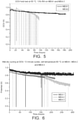
- the average MEA voltage durability for the three MEAs is shown in Figure 7 .
- MEA 5 and MEA 6 each experience a dramatic decrease in the performance (cell voltage) at around 750 hours, whereas MEA 4 maintains a very stable cell voltage throughout the 2000 hours of the test.
- This fuel cell stack durability test clearly demonstrates the significantly enhanced durability that is derived from the MEA using the reinforced membrane of the invention compared to other MEAs employing non-reinforced, but otherwise similar, membranes.
- the MEAs of the invention show improved durability beyond that demonstrated from the corresponding unreinforced membranes or membranes using a different type of reinforcement.
- the inventors believe this may be due to the phase separation and continuity of the electrospun mat and the ionic cross-linking (acid-base interaction, or hydrogen bonding) between the ion-conducting polymer and the surface of the nanofibres in the electrospun web.
- the electrospun mat allows greater swelling in the thickness direction as the fibres can move with respect to each other in this direction, but restricts swelling in the in-plane direction as the fibres are not elastic.
- heterocyclic based polymers used to form the electrospun mat have antioxidant properties and can contribute to the stability of the electrolyte membrane by scavenging damaging species such as peroxy free radicals. Due to these antioxidant properties, it may be that it is no longer necessary to incorporate antioxidants or hydrogen peroxide decomposition catalysts, such as ceria, into the membrane.
Landscapes
- Chemical & Material Sciences (AREA)
- Chemical Kinetics & Catalysis (AREA)
- Engineering & Computer Science (AREA)
- Manufacturing & Machinery (AREA)
- General Chemical & Material Sciences (AREA)
- Electrochemistry (AREA)
- Sustainable Energy (AREA)
- Sustainable Development (AREA)
- Life Sciences & Earth Sciences (AREA)
- Organic Chemistry (AREA)
- Polymers & Plastics (AREA)
- Health & Medical Sciences (AREA)
- Medicinal Chemistry (AREA)
- Materials Engineering (AREA)
- Crystallography & Structural Chemistry (AREA)
- Inorganic Chemistry (AREA)
- Composite Materials (AREA)
- Metallurgy (AREA)
- Fuel Cell (AREA)
- Conductive Materials (AREA)
- Inert Electrodes (AREA)
- Nonwoven Fabrics (AREA)
Description
- The present invention relates to an electrolyte membrane and its use in an electrochemical device, in particular its use in a proton exchange membrane fuel cell.
- A fuel cell is an electrochemical cell comprising two electrodes separated by an electrolyte. A fuel, e.g. hydrogen, an alcohol such as methanol or ethanol, or formic acid, is supplied to the anode and an oxidant, e.g. oxygen or air, is supplied to the cathode. Electrochemical reactions occur at the electrodes, and the chemical energy of the fuel and the oxidant is converted to electrical energy and heat. Electrocatalysts are used to promote the electrochemical oxidation of the fuel at the anode and the electrochemical reduction of oxygen at the cathode.
- Fuel cells are usually classified according to the nature of the electrolyte employed. Often the electrolyte is a solid polymeric membrane, in which the membrane is electronically insulating but ionically conducting. In the proton exchange membrane fuel cell (PEMFC) the membrane is proton conducting, and protons, produced at the anode, are transported across the membrane to the cathode, where they combine with oxygen to form water.
- A principal component of the PEMFC is the membrane electrode assembly (MEA), which is essentially composed of five layers. The central layer is the polymer ion-conducting membrane. On either side of the ion-conducting membrane there is an electrocatalyst layer, containing an electrocatalyst designed for the specific electrolytic reaction. Finally, adjacent to each electrocatalyst layer there is a gas diffusion layer which is porous and electrically conducting and allows the reactants to reach the electrocatalyst layer and conduct the electric current that is generated by the electrochemical reactions.
- Conventional ion-conducting membranes used in PEMFCs are generally formed from sulphonated fully-fluorinated polymeric materials (often generically referred to as perfluorinated sulphonic acid (PFSA) ionomers). As an alternative to PFSA type ionomers, it is possible to use ion-conducting membranes based on partially fluorinated or non-fluorinated hydrocarbon sulphonated or phosphonated polymers. Recent developments in PEMFCs require membranes to be thinner (<50 µm) and of higher ion exchange capacity (IEC) or lower equivalent weight (EW) due to the advantages obtained (improved ionic conductivity, improved water transport etc) and thus, in order to provide the mechanical properties required to increase resistance to premature failure, a reinforcement, typically expanded polytetrafluoroethylene (ePTFE), is embedded within the membrane.
- Although such reinforced membranes often have lower proton conductivity when compared to an unreinforced membrane of the same thickness, the improvement in mechanical properties has enabled thinner membranes of lower electrical resistance to be used.
- Other types of reinforcement have also been proposed, for example as disclosed in
WO2011/149732 . - Other types of electrolyte membranes not according to the current invention are disclosed in patent number
EP1477515 A1 . - Although reinforced membranes such as those hereinbefore described have allowed thinner membranes to be used whilst maintaining mechanical strength, deficiencies still exist. In particular, limitations are seen in practical operation in which the conditions of humidity can vary quite significantly over short periods of time from relatively high levels (such as on start up from cold conditions) to quite dry levels (operation at maximum rated power density) where the membrane can degrade to a higher level than acceptable. In accelerated stress tests designed to mimic and accelerate this operation, a wet/dry cycling accelerated stress testing induces swelling/de-swelling of the membrane such that these membrane degradation effects can be more rapidly observed.
- It is an object of the present invention to provide an improved electrolyte membrane, suitably for use in PEMFCs and PEM electrolysers.
- The invention provides an electrolyte membrane according to
claim 1 and comprising: - (i) a porous mat formed from entangled nanofibres, wherein the nanofibres are spun nanofibers, and wherein the nanofibers are composed of a non-ionically conducting heterocyclic-based polymer, the heterocyclic-based polymer comprising basic functional groups and being soluble in organic solvent; and
- (ii) an ion-conducting polymer which is a partially- or fully-fluorinated sulphonic acid polymer;
-
-
Figure 1 : Schematic representation of an electrolyte membrane of the invention. -
Figure 2 : SEM image of the electrospun polybenzimidazole (PBI) nanofibre mat and fibre size distribution of the example. -
Figure 3 : Effect of the use of a solvent sheath on PBI fibre size distribution. -
Figure 4 : Cross-sectional SEM of the membrane of Example 1. -
Figure 5 : OCV hold test at 85 °C, 13% RH onMEA 1 andMEA 3. -
Figure 6 : Wet-dry cycling at OCV, onMEA 1,MEA 2 andMEA 3. -
Figure 7 : Performance during the stack durability testing ofMEA 4, MEA 5 and MEA 6. - Preferred and/or optional features of the invention will now be set out. Any aspect of the invention may be combined with any other aspect of the invention, unless the context demands otherwise. Any of the preferred or optional features of any aspect may be combined, singly or in combination, with any aspect of the invention, unless the context demands otherwise.
- The invention provides an electrolyte membrane comprising a porous mat of nanofibres, the porous mat being impregnated with an ion-conducting polymer.
- The porous mat provides mechanical reinforcement to the electrolyte membrane.
- The porous mat is formed from entangled nanofibres of a non-ionically conducting heterocyclic-based polymer comprising basic functional groups. The heterocyclic-based polymer is soluble in organic solvent, and in particular the polymer is soluble in N-methylpyrrolidone (NMP), dimethylformamide (DMF), dimethylacetamide (DMAc) or dimethylsulphoxide (DMSO) , suitably DMAc or DMSO and preferably DMAc.
- The nanofibres suitably have an average diameter of 100-400 nm, suitably 100-300 nm and preferably 150-250 nm.
- The length of the nanofibres is not material to the invention, but each nanofibres should be sufficiently long (for example several centimetres) to become entangled, either with one or more other nanofibres or with itself.
- The nanofibres are spun nanofibres, i.e. the nanofibres are formed using a spinning technique. Examples of suitably spinning techniques include, but are not limited to, electrospinning and force spinning
- Heterocyclic polymers, preferably basic heterocyclic polymers, include polybenzimidazoles, poly(pyridine), poly(pyrimidine), polybenzthiazoles, polyoxadiazoles, polyquinolines, polyquinoxalines, polythiadiazoles, polytriazoles, polyoxazoles and polythiazoles and derivatives thereof. Suitably, the polymer is a functionalised polyazole or a zwitterionic polyazole, such as a polybenzimidazole, polytriazole, polythiazole and polydithiazole and their derivatives; most suitably a polybenzimidazole.
- Suitably, the nanofibres are formed from a single heterocyclic-based polymer and not a blend of two or more heterocyclic-based polymers.
- The heterocyclic-based polymer may also be cross-linked; i.e. one polymer chain is bonded to another polymer chain. Cross-linking may improve the mechanical stability of the electrolyte membrane.
- The heterocyclic-based polymer may also have inherent radical scavenging properties. Such properties will be beneficial in the electrolyte membrane and provide protection against chemical degradation mechanisms such as damage from peroxy radical species. This will thus also contribute to providing a more durable membrane. The use of heterocyclic-based polymer having such properties will also obviate the need for the addition of additional materials with radical scavenging properties or hydrogen peroxide decomposition catalysts such as cerium cations, cerium dioxide, manganese dioxide or other additives into the electrolyte membrane, thus avoiding the associated disadvantages of incorporating these materials.
- The porous mat has an open structure and porosity in the range of 70-98%, suitably 80-95%, suitably 85-95% and preferably 90-95%. The porosity is determined from the ratio of the volumetric mass of the porous mat, determined from its geometrical dimensions and its mass, to the known density of the polymer.
- The porous mat has an average basis weight in the range 1 g/m2 to 7 g/m2 , suitably in the range 1.5 g/m2 to 3 g/m2.
- The porous mat in the electrolyte membrane suitably has a maximum thickness of 50 µm, 30 µm, suitably 25 µm and preferably 20 µm.
- The porous mat in the electrolyte membrane suitably has a minimum thickness of 5 µm suitably 10 µm.
- To form the porous mat, nanofibres are formed, suitably by a spinning technique, onto a suitable substrate or surface. For example, the nanofibres may be formed using electrospinning: the electrospinning solution comprising the heterocyclic based polymer in a suitable solvent is pushed through a needle using a syringe pump and applying a high voltage to the needle. The mat of electrospun nanofibres is collected on a grounded rotating drum collector moving translationally and rotationally which is set at some distance from the needle, such as around 10-15 cm from the needle. The fibre morphology is obtained through control of the solution parameters, such as concentration, whereas mat thickness and uniformity is controlled through deposition time and collector rotation/translation speed.
- The porous mat is not subjected to any further processing, for example, any densification processes, such as calendaring, or welding etc.
- The ion-conducting polymer is suitably a proton-conducting polymer and in particular a partially- or fully-fluorinated sulphonic acid polymer. Examples of suitable proton-conducting polymers include the perfluorosulphonic acid ionomers (e.g. Nafion® (E.I. DuPont de Nemours and Co.), Aciplex® (Asahi Kasei), Aquivion® (Solvay Specialty Polymer), Flemion® (Asahi Glass Co.).
- At least 80% of the porous mat is impregnated with ion-conducting polymer suitably at least 90 %, suitably at least 95% and ideally 100% of the pores of the porous mat are filled with ion-conducting polymer
- Suitably, excess ion-conducting polymer is present on both surfaces of the electrolyte membrane to aid adhesion to a catalyst layer.
- The porous mat may be impregnated with the ion-conducting polymer by the following process:
A layer of ion-conducting polymer (in solution/dispersion) is cast onto a carrier material. While the layer of ion-conducting polymer is still wet, the porous nanofibre mat is laid into the wet layer and the ion-conducting polymer impregnates into one face of the porous mat. A further layer of ion-conducting polymer is applied to a second face of the porous mat and impregnates into the porous mat from the second face. The impregnated porous mat is dried and suitably annealed to form the electrolyte membrane. - The solution/dispersion of ion-conducting polymer may comprise additional components, for example short nanofibres, e.g. from 1 to 50 µm.
- Alternative methods for impregnating the porous mat with ion-conducting polymer will be known to those skilled in the art.
- In the final electrolyte membrane of the invention, the weight ratio of ion-conducting polymer : nanofibres is suitably greater than 70:30 and preferably greater than 90:10. Suitably, the ion-conducting polymer : nanofibres ratio is less than 98:2. In this context, nanofibres refers to the nanofibres in the porous mat.
- The thickness of the porous mat in the electrolyte membrane is distributed across at least 80%, suitably at least 85%, and most suitably at least 90%, of the thickness of the final electrolyte membrane. The porous mat extends across the thickness of the membrane, such that the thickness of the electrolyte membrane and the thickness of the porous mat are essentially equal; however, practically, the thickness of the electrolyte membrane may be slightly thicker than that of the porous mat, such that the thickness of the porous mat is at most 99%, such as 95% of the thickness of the electrolyte membrane.
- Having the porous mat distributed across at least 80% of the thickness of the electrolyte membrane enhances the stabilisation (mechanical and chemical) of the final electrolyte membrane.
- An electrolyte membrane of the invention may comprise more than one porous mat e.g. two porous mats distributed across at least 80% of the thickness of the electrolyte membrane.
-
Figure 1 shows a schematic representation of an electrolyte membrane of the invention. - The invention also provides a catalysed electrolyte membrane comprising a catalyst layer and an electrolyte membrane of the invention.
- The catalyst layer comprises one of more electrocatalysts. The one or more electrocatalysts are independently a finely divided unsupported metal powder, or a supported catalyst wherein small nanoparticles are dispersed on electrically conducting particulate carbon supports. The electrocatalyst metal is suitably selected from
- (i) the platinum group metals (platinum, palladium, rhodium, ruthenium, iridium and osmium),
- (ii) gold or silver,
- (iii) a base metal,
- The exact electrocatalyst used will depend on the reaction it is intended to catalyse and its selection is within the capability of the skilled person.
- The catalyst layer is suitably applied to a first and/or second face of the electrolyte membrane as an ink, either organic or aqueous (but preferably aqueous). The ink may suitably comprise other components, such as ion-conducting polymer as described in
EP0731520 , which are included to improve the ionic conductivity within the layer. Alternatively, the catalyst layer can be applied by the decal transfer of a previously prepared catalyst layer. - The catalyst layer may further comprise additional components. Such additional components include, but are not limited to, a catalyst which facilitates oxygen evolution and therefore will be of benefit in cell reversal situations and high potential excursions, or a hydrogen peroxide decomposition catalyst. Examples of such catalysts and any other additives suitable for inclusion in the catalyst layer will be known to those skilled in the art.
- The invention further provides a membrane electrode assembly comprising an electrolyte membrane of the invention and a gas diffusion electrode on a first and/or second face of the electrolyte membrane.
- The invention further provides a membrane electrode assembly comprising a catalysed electrolyte membrane of the invention and a gas diffusion layer present on the at least one catalyst layers.
- The membrane electrode assembly may be made up in a number of ways including, but not limited to:
- (i) an electrolyte membrane of the invention may be sandwiched between two gas diffusion electrodes (one anode and one cathode);
- (ii) a catalysed electrolyte membrane of the invention having a catalyst layer on one side may be sandwiched between a gas diffusion layer and a gas diffusion electrode, the gas diffusion layer contacting the side of the catalysed electrolyte membrane having the catalyst component or;
- (iii) a catalysed electrolyte membrane of the invention having a catalyst component on both sides may be sandwiched between two gas diffusion layers.
- The anode and cathode gas diffusion layers are suitably based on conventional gas diffusion substrates. Typical substrates include non-woven papers or webs comprising a network of carbon fibres and a thermoset resin binder (e.g. the TGP-H series of carbon fibre paper available from Toray Industries Inc., Japan or the H2315 series available from Freudenberg FCCT KG, Germany, or the Sigracet® series available from SGL Technologies GmbH, Germany or AvCarb® series from Ballard Power Systems Inc., or woven carbon cloths. The carbon paper, web or cloth may be provided with a further treatment prior to being incorporated into a MEA either to make it more wettable (hydrophilic) or more wet-proofed (hydrophobic). The nature of any treatments will depend on the type of fuel cell and the operating conditions that will be used. The substrate can be made more wettable by incorporation of materials such as amorphous carbon blacks via impregnation from liquid suspensions, or can be made more hydrophobic by impregnating the pore structure of the substrate with a colloidal suspension of a polymer such as PTFE or polyfluoroethylenepropylene (FEP), followed by drying and heating above the melting point of the polymer. For applications such as the PEMFC, a microporous layer may also be applied to the gas diffusion substrate on the face that will contact the electrocatalyst layer. The microporous layer typically comprises a mixture of a carbon black and a polymer such as polytetrafluoroethylene (PTFE).
- The invention further provides a fuel cell comprising an electrolyte membrane, a catalysed electrolyte membrane or a membrane electrode assembly as hereinbefore described. In one embodiment, the fuel cell is a PEMFC.
- In addition to being used in PEMFCs, the electrolyte membrane of the invention will find use in any electrochemical device requiring such an ion-conducting polymer membrane, for example an electrolyser.
- The invention will be further described with reference to the following example which is illustrative and not limiting of the invention.
- Poly[2,2'-(m-phenylene)-5,5'-bibenzimidazole] (PBI), obtained from PBI Performance Products Inc., was electrospun from a 13% solution in dimethyl acetamide (DMAc) using the following parameters: 15 kV applied voltage, 0.12 mL/hr flow rate; needle collector distance of 10 cm; drum collector rotation speed of 800 rpm; and translational speed of 10 mm/s. The electrospun mat was removed from the drum.
- The PBI electrospun mat comprises randomly oriented nanofibres having an average fibre diameter of 200 nm, with a relatively narrow fibre diameter distribution between 140 and 280 nm, and are several tens of microns in length.
Figure 2 provides a scanning electron microscope (SEM) image of the electrospun mat showing the fibres are randomly oriented. Also shown inFigure 2 is a graph showing the fibre diameter distribution. - The thickness of the PBI nanofibres can be further controlled using co-axial needle electrospinning. The core solution is the PBI solution, and the sheath solution is DMAc. Through the use of a solvent sheath the evaporation and drying of the fibres that occurs during electrospinning is delayed, which results in greater stretching of the polymer nanofibres, and in thinner nanofibres in the final electrospun mat. Using a core/sheath flow rate ratio of 2/1, the average fibre diameter is 120 µm (range 60-180 nm) (see
Figure 3 ). - The electrospun PBI mat has a thickness of 10µm, a porosity of 83% and a basis weight of 2.27 g/m2.
- A dispersion of a Aquivion® PFSA of equivalent weight 700 g/mol from Solvay Specialty Polymers (13% w/v in 60/35/5 in H2O/1-propanol/DMAc) was cast onto a Teflon plate using the doctor blade method. The PBI electrospun mat was then placed directly on top of the cast PFSA dispersion. Impregnation of the cast PFSA dispersion into the nanofibre mat was confirmed visually, and a second layer of PFSA dispersion was then cast on top of the PBI electrospun mat. The overall membrane thickness was controlled through the gate thickness of the doctor blade. The cast electrolyte membrane was dried first at room temperature, followed by 80 °C overnight and then hot pressed (25 kg/cm2) at elevated temperature (160 °C).
- After solvent removal and hot-pressing, the electrolyte membrane had a nominal thickness of 30µm and the electrospun PBI mat extended across approximately 85% of the thickness of the electrolyte membrane. The weight ratio of PFSA : nanofibres in the electrolyte membrane was 90 : 10.
- A SEM image of the electrolyte membrane is given in
Figure 4 . Cross-section SEM was done by freeze-fracturing the samples in liquid nitrogen.Figure 4 shows that the electrospun mat allows for some displacement of the fibres during impregnation, resulting in the presence of the fibres throughout the cross-section of the electrolyte membrane. This has the benefit of reducing the barrier to proton conduction, as there is no PFSA-deficient region within the electrolyte membrane. It also allows for greater flexibility with the electrolyte membrane to accommodate mechanical stresses due to swelling. There was no visible separation between the nanofibres and the PFSA matrix after freeze-fracture, indicating an excellent interface between the electrospun mat and the PFSA. In the electrolyte membrane, the nanofibres appear to be fully immersed in the PFSA and the interface between the two is not distinct, indicating strong attachment of the PFSA to the surface of the nanofibres. - A solution of polyethersulphone (PES) of 20 wt% in DMAc/acetone was electrospun at 25 °C onto a rotating and translating drum collector. The nanofibre mat was collected and pressed at 140 °C. A dispersion of a Aquivion® PFSA of equivalent weight 700 g/mol from Solvay Specialty Polymers (13% w/v in 70/30 in H2O/1-propanol) was cast onto a Teflon plate using the doctor blade method. The PES electrospun mat was then placed directly on top of the cast PFSA dispersion. A second layer of PFSA dispersion was then cast on top of the PES electrospun mat. The overall membrane thickness was controlled through the gate thickness of the doctor blade. The cast electrolyte membrane was dried at 50 °C, then at 120 °C and then 145 °C.
- A 30µm unreinforced membrane prepared from Aquivion® PFSA with an equivalent weight of 790 g/mol (EW 790).
- A 30µm unreinforced membrane prepared from Aquivion® PFSA with an equivalent weight of 700 g/mol (EW 700), as used in Example 1.
- Swelling, water uptake and proton conductivity measurements of the membranes were measured at 80 °C.
- The in-plane proton conductivity was determined on samples of dimension ca. 25 × 5 mm using a Bekktech 4-point probe set-up and measurement cell with controlled temperature and relative humidity (RH). Resistance measurements were performed at 80 and 110 °C over the RH range of 50-95%. The measurements at 110 °C were carried out at a cell pressure of 206 kPa. The results are given in Table 1 as an average of three measurements. Membrane water uptake was determined by weighing samples of
dimensions 3 × 3 cm (cut using a template) before and after immersion in water at 80 °C overnight. The membrane dimensional swelling was determined on the same samples by measuring the sample dimensions before and after immersion in water.Table 1 Swelling (vol%) Mass Uptake (%) Proton Conductivity at 80 °C and 95% RH (mS cm-1) Example 1 19 100 173 Example 3 66 59 126 Example 4 135 141 192 - The percentage swelling in water is much reduced for the membrane of Example 1 compared to the membranes of Examples 3 and 4, which is believed to be due to the ionic interaction between the electrospun PB1 mat and the PFSA ionomer. The proton conductivity of Example 1 is higher than that of Example 3 and comparable to that of Example 4.
- Mechanical tensile strength was measured using elastic modulus and elongation at break. Mechanical tensile measurements were performed on a Zwick Roell Z1.0 instrument with a 200N static load cell equipped with a controlled humidity/temperature chamber and TestXpert V11.0 software. The tests were performed on samples of 100 × 5 mm strips using a draw rate of 1 mm/s and a clamp distance of 10 mm. For measurements at elevated temperature/RH, the samples were kept under the required conditions overnight, then mounted and equilibrated for 1h in the sample chamber and pre-tensioned before the measurements to take into account any swelling of the membrane. The results are given in Table 2.
Table 2 Conditions E (MPa) Elongation at Break (%) Example 1 Ambient, RT 539 ± 10 25 ± 5 70 °C, 80% RH 145 ± 3 44 ± 20 Example 3 Ambient, RT 149 ± 29 450 70 °C, 80% RH 48 ± 5 557 Example 4 Ambient, RT 182 313 70 °C, 80 % RH 40 315 - The elastic modulus and yield point are all significantly higher for the membrane of Example 1 than the membranes of Examples 3 and 4, demonstrating that the membrane of Example 1 is stiffer and stronger, having lower elongation at break.
- MEA 1: The membrane of Example 1 and electrodes were cut using templates to 52×52 mm, and a subgasket was used to define an active area of 25cm2. The electrodes were standard electrodes having a platinum catalyst loading of 0.2 mg/cm2 at the anode and 0.4 mg/cm2 at the cathode. The MEAs were fabricated by hot-pressing at 150°C for 5 minutes.
- MEA 2 (Comparative):
MEA 2 was prepared using the membrane of Example 2 following the fabrication method as described forMEA 1. - MEA 3 (Comparative):
MEA 3 was prepared using the membrane of Example 3, following the fabrication method as described forMEA 1. - MEA 4 :
MEA 4 was prepared in a similar manner to that described above forMEA 1, using the membrane of Example 1, with the exception that the active area was 45cm2 and the MEA was fabricated by hot-pressing at 170°C to 2 minutes. - MEA 5 (Comparative):
MEA 5 was prepared using the membrane of Example 3 following the fabrication method as described forMEA 4. - MEA 6 (Comparative):
MEA 6 was prepared using the membrane of Example 4, following the fabrication method as described forMEA 4. - OCV hold testing was performed under the following conditions to assess the durability of the membrane: Membrane electrode assemblies were held at open circuit voltage at 85 °C and 13% RH and the decrease of the cell voltage was monitored over time. As can be seen in
Figure 5 ,MEA 3 showed a significant drop in OCV, whereasMEA 1 shows much less decrease in OCV. - Wet-dry cycling test was performed at 80 °C at OCV by cycling from 0% RH (10 minutes) to 90 °C dewpoint (10 minutes) to further assess the durability of the membranes against volumetric changes caused by hydration/dehydration.
Figure 6 shows thatMEA 1 is much more stable compared toMEA 2 andMEA 3. After 150 hours,MEA 2 andMEA 3 shows an increase in the OCV decay rate whereasMEA 1 remains stable and shows a significantly reduced decay rate compared toMEA 2 andMEA 3, showing the nanofibre reinforcement provides mechanical strength and integrity against the stresses caused by volumetric changes upon hydration and dehydration, resulting in greatly improved stability. - A short fuel cell stack comprising 9 MEAs of active area 45cm2 was built comprising 3 MEAs each of
MEA 4,MEA 5 andMEA 6. The stack was operated under an accelerated durability test protocol, designed to replicate practical load cycling conditions for a fuel cell operating in the real environment. The test protocol included repeated periods of constant high current operation, followed by cycling between high current and low current conditions, and then switching from low current condition to shut-down and start up to low current conditions (i.e. repeated on-off cycling). The rapid cycling between these practical operational modes was designed to accelerate, over a shorter time, the performance characteristics that would be seen in a practical fuel cell operation over 10's of thousands of hours of real life operation. The accelerated testing cycles were performed at 50kPag inlet pressure and 30% inlet relative humidity (RH) at 80°C stack temperature. Gases were supplied at 1.5 × stoichiometry for anode and 2.0 × stoichiometry for the cathode. The durability test was run for almost 2,000 hours. Periodically during the durability test protocol the performance of the MEAs in the stack was measured by miming a current vs voltage polarisation. These polarisation tests were performed at 70°C stack temperature, ambient pressure, 100%RH on both anode and cathode. From the polarisation measurements operating on hydrogen/air a plot of the individual cell voltages versus time at a current density of 0.3Acm-2 were made. The cell voltages from each of the MEA typesMEA 4,MEA 5 andMEA 6 were averaged from the 3 MEAs of each type incorporated in the short stack. - The average MEA voltage durability for the three MEAs is shown in
Figure 7 . As can be seen,MEA 5 andMEA 6 each experience a dramatic decrease in the performance (cell voltage) at around 750 hours, whereasMEA 4 maintains a very stable cell voltage throughout the 2000 hours of the test. This fuel cell stack durability test clearly demonstrates the significantly enhanced durability that is derived from the MEA using the reinforced membrane of the invention compared to other MEAs employing non-reinforced, but otherwise similar, membranes. - Overall, from the testing results it can be seen that the MEAs of the invention show improved durability beyond that demonstrated from the corresponding unreinforced membranes or membranes using a different type of reinforcement.
- Without wishing to be bound by theory, the inventors believe this may be due to the phase separation and continuity of the electrospun mat and the ionic cross-linking (acid-base interaction, or hydrogen bonding) between the ion-conducting polymer and the surface of the nanofibres in the electrospun web. In addition, the electrospun mat allows greater swelling in the thickness direction as the fibres can move with respect to each other in this direction, but restricts swelling in the in-plane direction as the fibres are not elastic.
- Furthermore, the heterocyclic based polymers used to form the electrospun mat have antioxidant properties and can contribute to the stability of the electrolyte membrane by scavenging damaging species such as peroxy free radicals. Due to these antioxidant properties, it may be that it is no longer necessary to incorporate antioxidants or hydrogen peroxide decomposition catalysts, such as ceria, into the membrane.
- It is also thought that the strong non-covalent interactions between the nanofibres and the ion-conducting polymer may allow for reforming, or self-healing of the electrolyte membrane after minor damage such as pin-hole formation during operation. Such a reforming process would be promoted by application of pressure/temperature (conditions which already exist in the fuel cell during operation).
Claims (14)
- An electrolyte membrane comprising:(i) a porous mat formed from entangled nanofibres, wherein the nanofibers are spun nanofibres, and wherein the nanofibres are composed of a non-ionically conducting heterocyclic-based polymer, the heterocyclic-based polymer comprising basic functional groups and being soluble in organic solvent; and(ii) an ion-conducting polymer which is a partially- or fully-fluorinated sulphonic acid polymer;wherein at least 80% of the porous mat is impregnated with ion-conducting polymer, and wherein the thickness of the porous mat in the electrolyte membrane is distributed across at least 80% of the thickness of the electrolyte membrane.
- An electrolyte membrane according to claim 1, wherein the heterocyclic-based polymer is selected from the group polybenzimidazoles, poly(pyridine), poly(pyrimidine), polybenzthiazoles, polyoxadiazoles, polyquinolines, polyquinoxalines, polythiadiazoles, polytriazoles, polyoxazoles and polythiazoles and derivatives thereof.
- An electrolyte membrane according to claim 1, wherein the heterocyclic-based polymer is a polyazole or a derivative thereof.
- An electrolyte membrane according to claim 3, wherein the polyazole is selected from the group consisting of polybenzimidazole, polytriazole, polythiazole and polydithiazole and their derivatives.
- An electrolyte membrane according to any preceding claim, wherein the nanofibres have an average diameter of 100-400 nm.
- An electrolyte membrane according to any preceding claim, wherein the porous mat has a porosity in the range of 70-98%.
- An electrolyte membrane according to any preceding claim, wherein the porous mat has an average basis weight in the range 1.0 g/m2 to 7 g/m2.
- An electrolyte membrane according to any preceding claim, wherein the ratio of ion-conducting polymer : nanofibres in the electrolyte membrane is greater than 70:30.
- A catalysed membrane comprising an electrolyte membrane according to any one of claim 1 to 8 and a catalyst layer on a first and/or second face of the electrolyte membrane.
- A membrane electrode assembly comprising an electrolyte membrane according to any one of claim 1 to 8 and a gas diffusion electrode on a first and/or second face of the electrolyte membrane.
- A membrane electrode assembly comprising a catalysed membrane according to claim 9 and a gas diffusion layer on the catalyst layer.
- A fuel cell comprising an electrolyte membrane according to any one of claims 1 to 8, a catalysed membrane according to claim 9 or a membrane electrode assembly according to claim 10 or 11.
- A fuel cell according to claim 12, wherein the fuel cell is a PEMFC.
- An electrolyser comprising an electrolyte membrane according to any one of claims 1 to 8.
Applications Claiming Priority (2)
| Application Number | Priority Date | Filing Date | Title |
|---|---|---|---|
| GBGB1413794.7A GB201413794D0 (en) | 2014-08-04 | 2014-08-04 | Membrane |
| PCT/GB2015/052253 WO2016020668A1 (en) | 2014-08-04 | 2015-08-04 | Membrane |
Publications (2)
| Publication Number | Publication Date |
|---|---|
| EP3177388A1 EP3177388A1 (en) | 2017-06-14 |
| EP3177388B1 true EP3177388B1 (en) | 2022-03-02 |
Family
ID=51587710
Family Applications (1)
| Application Number | Title | Priority Date | Filing Date |
|---|---|---|---|
| EP15749849.4A Active EP3177388B1 (en) | 2014-08-04 | 2015-08-04 | Membrane |
Country Status (8)
| Country | Link |
|---|---|
| US (1) | US10777833B2 (en) |
| EP (1) | EP3177388B1 (en) |
| JP (1) | JP6707519B2 (en) |
| KR (1) | KR102473497B1 (en) |
| CN (1) | CN107078327B (en) |
| DK (1) | DK3177388T3 (en) |
| GB (1) | GB201413794D0 (en) |
| WO (1) | WO2016020668A1 (en) |
Families Citing this family (8)
| Publication number | Priority date | Publication date | Assignee | Title |
|---|---|---|---|---|
| KR102401756B1 (en) * | 2016-02-18 | 2022-05-26 | 도레이 카부시키가이샤 | Composite polymer electrolyte membrane, membrane electrode composite using same, polymer electrolyte fuel cell |
| EP3609008B1 (en) | 2017-04-03 | 2021-06-02 | Asahi Kasei Kabushiki Kaisha | Composite polymer electrolyte membrane |
| KR102293177B1 (en) | 2017-11-30 | 2021-08-26 | 코오롱인더스트리 주식회사 | Polymer electrolyte membrane, method for manufacturing the same and membrane-electrode assembly comprising the same |
| KR102431106B1 (en) * | 2018-05-25 | 2022-08-09 | 주식회사 엘지화학 | Resin composition for preparing of reinforced membrane, preparation method for thereof and battery comprising the same |
| DE102019104561A1 (en) * | 2019-02-22 | 2020-08-27 | Hahn-Schickard-Gesellschaft für angewandte Forschung e.V. | Method for producing a composite layer, electrochemical unit and use of the composite layer |
| CN114391192A (en) | 2019-09-20 | 2022-04-22 | 东丽株式会社 | Composite polymer electrolyte membrane, electrolyte membrane with catalyst layer, membrane electrode assembly, and solid polymer fuel cell |
| DE102020215405A1 (en) | 2020-12-07 | 2022-06-09 | Robert Bosch Gesellschaft mit beschränkter Haftung | Method for producing a membrane electrode assembly (MEA), membrane electrode assembly (MEA) and fuel cell |
| GB2624228A (en) * | 2022-11-11 | 2024-05-15 | Johnson Matthey Hydrogen Technologies Ltd | Reinforced ion-conducting membrane |
Family Cites Families (18)
| Publication number | Priority date | Publication date | Assignee | Title |
|---|---|---|---|---|
| GB9504713D0 (en) | 1995-03-09 | 1995-04-26 | Johnson Matthey Plc | Improved electrocatalytic material |
| KR100527322B1 (en) * | 1997-05-06 | 2006-01-27 | 소니 가부시끼 가이샤 | Sheet for Forming a Polymer Gel Electrolyte, Polymer Gel Electrolyte Using Such a Sheet and Method for the Manufacture Thereof |
| US6248469B1 (en) | 1997-08-29 | 2001-06-19 | Foster-Miller, Inc. | Composite solid polymer electrolyte membranes |
| US6689501B2 (en) * | 2001-05-25 | 2004-02-10 | Ballard Power Systems Inc. | Composite ion exchange membrane for use in a fuel cell |
| CN100381487C (en) * | 2002-02-15 | 2008-04-16 | 东洋纺织株式会社 | Cluster ion exchange membrane and electrolyte membrane electrode connection body |
| JP2005068396A (en) | 2003-04-18 | 2005-03-17 | Toyobo Co Ltd | Composite ion-exchange membrane |
| KR101367557B1 (en) | 2005-07-29 | 2014-02-25 | 도요보 가부시키가이샤 | Polyamide imide fiber non-woven fabric composed of the fiber, process for manufacture of the non-woven fabric, and separator for electronic component |
| KR101000214B1 (en) * | 2008-05-28 | 2010-12-10 | 주식회사 엘지화학 | Ion conductive resin fiber, ion conductive hybrid membrane, membrane-electrode assembly and fuel cell |
| KR101144398B1 (en) * | 2009-01-15 | 2012-05-10 | 서울대학교산학협력단 | Polybenzimidazole-based polymer with basic substituent and electrolyte membrane comprising the same |
| DE112010003385T5 (en) | 2009-08-25 | 2012-06-06 | Kolon Fashion Material, Inc. | Polymer electrolyte membrane for a fuel cell and method for its manufacture |
| EP3147982A1 (en) * | 2010-05-25 | 2017-03-29 | 3M Innovative Properties Company | Reinforced electrolyte membrane |
| US9537166B2 (en) * | 2010-06-08 | 2017-01-03 | Rensselaer Polytechnic Institute | Method for the production of an electrochemical cell |
| KR101433133B1 (en) | 2011-03-31 | 2014-08-25 | 코오롱인더스트리 주식회사 | Polymer Electrolyte Membrane for Fuel Cell and Method for Manufacturing the Same |
| JP5867828B2 (en) | 2011-04-28 | 2016-02-24 | 日本バイリーン株式会社 | Composite membrane and manufacturing method thereof |
| KR20130110569A (en) | 2012-03-29 | 2013-10-10 | 코오롱인더스트리 주식회사 | The electrolyte membrane for and method for preparing the same |
| US20140134506A1 (en) | 2012-11-06 | 2014-05-15 | Francis John Kub | Proton Exchange Membrane |
| KR101995527B1 (en) | 2012-12-28 | 2019-07-02 | 코오롱인더스트리 주식회사 | Reinforced composite membrane for fuel cell and membrane-electrode assembly for fuel cell comprising the same |
| JP2015065153A (en) * | 2013-08-30 | 2015-04-09 | 三菱製紙株式会社 | Separator for electrochemical element, method of manufacturing separator for electrochemical element, and electrochemical element |
-
2014
- 2014-08-04 GB GBGB1413794.7A patent/GB201413794D0/en not_active Ceased
-
2015
- 2015-08-04 WO PCT/GB2015/052253 patent/WO2016020668A1/en active Application Filing
- 2015-08-04 KR KR1020177005672A patent/KR102473497B1/en active IP Right Grant
- 2015-08-04 JP JP2017505551A patent/JP6707519B2/en active Active
- 2015-08-04 US US15/329,850 patent/US10777833B2/en active Active
- 2015-08-04 EP EP15749849.4A patent/EP3177388B1/en active Active
- 2015-08-04 CN CN201580041972.8A patent/CN107078327B/en active Active
- 2015-08-04 DK DK15749849.4T patent/DK3177388T3/en active
Also Published As
| Publication number | Publication date |
|---|---|
| DK3177388T3 (en) | 2022-04-19 |
| KR102473497B1 (en) | 2022-12-05 |
| JP2017532716A (en) | 2017-11-02 |
| GB201413794D0 (en) | 2014-09-17 |
| WO2016020668A1 (en) | 2016-02-11 |
| US10777833B2 (en) | 2020-09-15 |
| US20170279142A1 (en) | 2017-09-28 |
| CN107078327B (en) | 2020-09-22 |
| KR20170038881A (en) | 2017-04-07 |
| EP3177388A1 (en) | 2017-06-14 |
| JP6707519B2 (en) | 2020-06-10 |
| CN107078327A (en) | 2017-08-18 |
Similar Documents
| Publication | Publication Date | Title |
|---|---|---|
| EP3177388B1 (en) | Membrane | |
| US9876234B2 (en) | Catalyst layer assembly | |
| US10381672B2 (en) | Reinforced composite membrane for fuel cell and membrane-electrode assembly for fuel cell comprising the same | |
| KR102300275B1 (en) | Ion-conducting membrane | |
| CN102047476B (en) | Ion-conductive resin fibers, ion-conductive composite membrane, membrane electrode assembly, and fuel cell | |
| KR20140124901A (en) | Membrane | |
| KR102175009B1 (en) | Membrane-electrode assembly for fuel cell, method for manufacturing of the same, and fuel cell comprising the same | |
| DK2869382T3 (en) | Improved diaphragm electrode devices | |
| KR101630212B1 (en) | A composite membrane comprising nonwoven PAI-PTM and sulfonated poly(arylene ether sulfone) as hydrocarbon-based electrolyte therein and the use thereof | |
| KR102672550B1 (en) | Multilayer reinforced composite electrolyte membrane and method of making the same | |
| KR102125412B1 (en) | Method for manufacturing hydrocarbon based reinforced polymer electrolyte membrane for fuel cell and reinforced polymer electrolyte membrane manufactured thereby | |
| Yu | Polybenzimidazole/porous poly (tetrafluoro ethylene) composite membranes | |
| WO2024189366A1 (en) | Reinforced ion-conducting membrane | |
| KR102701887B1 (en) | Polymer electrolyte membrane, membrane-electrode assembly comprising the same and fuel cell | |
| WO2024100413A1 (en) | Reinforced ion-conducting membrane | |
| EP4037044A1 (en) | Polymer electrolyte membrane, membrane-electrode assembly comprising same, and fuel cell | |
| KR102163538B1 (en) | Method for manufacturing ion exchanging membrane, ion exchanging membrane manufactured by using the same, membrane-electrode assembly and fuel cell comprising the ion exchanging membrane | |
| KR102154101B1 (en) | A composite membrane comprising nonwoven PAN support and hydrocarbon-based electrolyte impregnated therein and the use thereof | |
| KR20230081646A (en) | Reinforced composite membrane for fuel cell, manufacturing method thereof, and membrane-electrode assembly for fuel cell comprising the same | |
| KR20220043873A (en) | Polymer electrolyte membrane, membrane-electrode assembly comprising the same and fuel cell | |
| KR20220099785A (en) | Electrochemically Active Composite Material for Polymer Electrolyte Membrane Fuel Cell | |
| US20200303753A1 (en) | Membrane and process |
Legal Events
| Date | Code | Title | Description |
|---|---|---|---|
| STAA | Information on the status of an ep patent application or granted ep patent |
Free format text: STATUS: THE INTERNATIONAL PUBLICATION HAS BEEN MADE |
|
| PUAI | Public reference made under article 153(3) epc to a published international application that has entered the european phase |
Free format text: ORIGINAL CODE: 0009012 |
|
| STAA | Information on the status of an ep patent application or granted ep patent |
Free format text: STATUS: REQUEST FOR EXAMINATION WAS MADE |
|
| 17P | Request for examination filed |
Effective date: 20170302 |
|
| AK | Designated contracting states |
Kind code of ref document: A1 Designated state(s): AL AT BE BG CH CY CZ DE DK EE ES FI FR GB GR HR HU IE IS IT LI LT LU LV MC MK MT NL NO PL PT RO RS SE SI SK SM TR |
|
| AX | Request for extension of the european patent |
Extension state: BA ME |
|
| DAV | Request for validation of the european patent (deleted) | ||
| DAX | Request for extension of the european patent (deleted) | ||
| STAA | Information on the status of an ep patent application or granted ep patent |
Free format text: STATUS: EXAMINATION IS IN PROGRESS |
|
| 17Q | First examination report despatched |
Effective date: 20181220 |
|
| STAA | Information on the status of an ep patent application or granted ep patent |
Free format text: STATUS: EXAMINATION IS IN PROGRESS |
|
| GRAP | Despatch of communication of intention to grant a patent |
Free format text: ORIGINAL CODE: EPIDOSNIGR1 |
|
| STAA | Information on the status of an ep patent application or granted ep patent |
Free format text: STATUS: GRANT OF PATENT IS INTENDED |
|
| RIC1 | Information provided on ipc code assigned before grant |
Ipc: H01M 8/0289 20160101ALI20211012BHEP Ipc: H01M 8/1062 20160101ALI20211012BHEP Ipc: H01M 8/106 20160101ALI20211012BHEP Ipc: H01M 8/1044 20160101ALI20211012BHEP Ipc: H01M 8/1039 20160101ALI20211012BHEP Ipc: H01M 8/1023 20160101ALI20211012BHEP Ipc: H01M 8/1018 20160101ALI20211012BHEP Ipc: B01D 71/62 20060101ALI20211012BHEP Ipc: B01D 71/32 20060101ALI20211012BHEP Ipc: B01D 69/02 20060101ALI20211012BHEP Ipc: B01D 69/12 20060101ALI20211012BHEP Ipc: B01D 67/00 20060101AFI20211012BHEP |
|
| INTG | Intention to grant announced |
Effective date: 20211103 |
|
| GRAS | Grant fee paid |
Free format text: ORIGINAL CODE: EPIDOSNIGR3 |
|
| GRAA | (expected) grant |
Free format text: ORIGINAL CODE: 0009210 |
|
| STAA | Information on the status of an ep patent application or granted ep patent |
Free format text: STATUS: THE PATENT HAS BEEN GRANTED |
|
| AK | Designated contracting states |
Kind code of ref document: B1 Designated state(s): AL AT BE BG CH CY CZ DE DK EE ES FI FR GB GR HR HU IE IS IT LI LT LU LV MC MK MT NL NO PL PT RO RS SE SI SK SM TR |
|
| REG | Reference to a national code |
Ref country code: GB Ref legal event code: FG4D |
|
| REG | Reference to a national code |
Ref country code: CH Ref legal event code: EP Ref country code: AT Ref legal event code: REF Ref document number: 1471796 Country of ref document: AT Kind code of ref document: T Effective date: 20220315 |
|
| REG | Reference to a national code |
Ref country code: DE Ref legal event code: R096 Ref document number: 602015077245 Country of ref document: DE |
|
| REG | Reference to a national code |
Ref country code: IE Ref legal event code: FG4D |
|
| REG | Reference to a national code |
Ref country code: DK Ref legal event code: T3 Effective date: 20220412 |
|
| REG | Reference to a national code |
Ref country code: LT Ref legal event code: MG9D |
|
| REG | Reference to a national code |
Ref country code: NL Ref legal event code: MP Effective date: 20220302 |
|
| PG25 | Lapsed in a contracting state [announced via postgrant information from national office to epo] |
Ref country code: SE Free format text: LAPSE BECAUSE OF FAILURE TO SUBMIT A TRANSLATION OF THE DESCRIPTION OR TO PAY THE FEE WITHIN THE PRESCRIBED TIME-LIMIT Effective date: 20220302 Ref country code: RS Free format text: LAPSE BECAUSE OF FAILURE TO SUBMIT A TRANSLATION OF THE DESCRIPTION OR TO PAY THE FEE WITHIN THE PRESCRIBED TIME-LIMIT Effective date: 20220302 Ref country code: NO Free format text: LAPSE BECAUSE OF FAILURE TO SUBMIT A TRANSLATION OF THE DESCRIPTION OR TO PAY THE FEE WITHIN THE PRESCRIBED TIME-LIMIT Effective date: 20220602 Ref country code: LT Free format text: LAPSE BECAUSE OF FAILURE TO SUBMIT A TRANSLATION OF THE DESCRIPTION OR TO PAY THE FEE WITHIN THE PRESCRIBED TIME-LIMIT Effective date: 20220302 Ref country code: HR Free format text: LAPSE BECAUSE OF FAILURE TO SUBMIT A TRANSLATION OF THE DESCRIPTION OR TO PAY THE FEE WITHIN THE PRESCRIBED TIME-LIMIT Effective date: 20220302 Ref country code: ES Free format text: LAPSE BECAUSE OF FAILURE TO SUBMIT A TRANSLATION OF THE DESCRIPTION OR TO PAY THE FEE WITHIN THE PRESCRIBED TIME-LIMIT Effective date: 20220302 Ref country code: BG Free format text: LAPSE BECAUSE OF FAILURE TO SUBMIT A TRANSLATION OF THE DESCRIPTION OR TO PAY THE FEE WITHIN THE PRESCRIBED TIME-LIMIT Effective date: 20220602 |
|
| REG | Reference to a national code |
Ref country code: AT Ref legal event code: MK05 Ref document number: 1471796 Country of ref document: AT Kind code of ref document: T Effective date: 20220302 |
|
| PG25 | Lapsed in a contracting state [announced via postgrant information from national office to epo] |
Ref country code: PL Free format text: LAPSE BECAUSE OF FAILURE TO SUBMIT A TRANSLATION OF THE DESCRIPTION OR TO PAY THE FEE WITHIN THE PRESCRIBED TIME-LIMIT Effective date: 20220302 Ref country code: LV Free format text: LAPSE BECAUSE OF FAILURE TO SUBMIT A TRANSLATION OF THE DESCRIPTION OR TO PAY THE FEE WITHIN THE PRESCRIBED TIME-LIMIT Effective date: 20220302 Ref country code: GR Free format text: LAPSE BECAUSE OF FAILURE TO SUBMIT A TRANSLATION OF THE DESCRIPTION OR TO PAY THE FEE WITHIN THE PRESCRIBED TIME-LIMIT Effective date: 20220603 Ref country code: FI Free format text: LAPSE BECAUSE OF FAILURE TO SUBMIT A TRANSLATION OF THE DESCRIPTION OR TO PAY THE FEE WITHIN THE PRESCRIBED TIME-LIMIT Effective date: 20220302 |
|
| REG | Reference to a national code |
Ref country code: DE Ref legal event code: R081 Ref document number: 602015077245 Country of ref document: DE Owner name: UNIVERSITE MONTPELLIER 2, FR Free format text: FORMER OWNERS: CENTRE NATIONAL DE LA RECHERCHE SCIENTIFIQUE, PARIS, FR; JOHNSON MATTHEY FUEL CELLS LIMITED, LONDON, GB; UNIVERSITE MONTPELLIER 2, MONTPELLIER, FR Ref country code: DE Ref legal event code: R081 Ref document number: 602015077245 Country of ref document: DE Owner name: JOHNSON MATTHEY HYDROGEN TECHNOLOGIES LIMITED, GB Free format text: FORMER OWNERS: CENTRE NATIONAL DE LA RECHERCHE SCIENTIFIQUE, PARIS, FR; JOHNSON MATTHEY FUEL CELLS LIMITED, LONDON, GB; UNIVERSITE MONTPELLIER 2, MONTPELLIER, FR Ref country code: DE Ref legal event code: R081 Ref document number: 602015077245 Country of ref document: DE Owner name: CENTRE NATIONAL DE LA RECHERCHE SCIENTIFIQUE, FR Free format text: FORMER OWNERS: CENTRE NATIONAL DE LA RECHERCHE SCIENTIFIQUE, PARIS, FR; JOHNSON MATTHEY FUEL CELLS LIMITED, LONDON, GB; UNIVERSITE MONTPELLIER 2, MONTPELLIER, FR Ref country code: DE Ref legal event code: R081 Ref document number: 602015077245 Country of ref document: DE Owner name: UNIVERSITE DE MONTPELLIER, FR Free format text: FORMER OWNERS: CENTRE NATIONAL DE LA RECHERCHE SCIENTIFIQUE, PARIS, FR; JOHNSON MATTHEY FUEL CELLS LIMITED, LONDON, GB; UNIVERSITE MONTPELLIER 2, MONTPELLIER, FR |
|
| REG | Reference to a national code |
Ref country code: BE Ref legal event code: HC Owner name: UNIVERSITE MONTPELLIER 2; FR Free format text: DETAILS ASSIGNMENT: CHANGE OF OWNER(S), CHANGE OF OWNER(S) NAME; FORMER OWNER NAME: JOHNSON MATTHEY FUEL CELLS LIMITED Effective date: 20220722 |
|
| PG25 | Lapsed in a contracting state [announced via postgrant information from national office to epo] |
Ref country code: NL Free format text: LAPSE BECAUSE OF FAILURE TO SUBMIT A TRANSLATION OF THE DESCRIPTION OR TO PAY THE FEE WITHIN THE PRESCRIBED TIME-LIMIT Effective date: 20220302 |
|
| PG25 | Lapsed in a contracting state [announced via postgrant information from national office to epo] |
Ref country code: SM Free format text: LAPSE BECAUSE OF FAILURE TO SUBMIT A TRANSLATION OF THE DESCRIPTION OR TO PAY THE FEE WITHIN THE PRESCRIBED TIME-LIMIT Effective date: 20220302 Ref country code: SK Free format text: LAPSE BECAUSE OF FAILURE TO SUBMIT A TRANSLATION OF THE DESCRIPTION OR TO PAY THE FEE WITHIN THE PRESCRIBED TIME-LIMIT Effective date: 20220302 Ref country code: RO Free format text: LAPSE BECAUSE OF FAILURE TO SUBMIT A TRANSLATION OF THE DESCRIPTION OR TO PAY THE FEE WITHIN THE PRESCRIBED TIME-LIMIT Effective date: 20220302 Ref country code: PT Free format text: LAPSE BECAUSE OF FAILURE TO SUBMIT A TRANSLATION OF THE DESCRIPTION OR TO PAY THE FEE WITHIN THE PRESCRIBED TIME-LIMIT Effective date: 20220704 Ref country code: EE Free format text: LAPSE BECAUSE OF FAILURE TO SUBMIT A TRANSLATION OF THE DESCRIPTION OR TO PAY THE FEE WITHIN THE PRESCRIBED TIME-LIMIT Effective date: 20220302 Ref country code: CZ Free format text: LAPSE BECAUSE OF FAILURE TO SUBMIT A TRANSLATION OF THE DESCRIPTION OR TO PAY THE FEE WITHIN THE PRESCRIBED TIME-LIMIT Effective date: 20220302 Ref country code: AT Free format text: LAPSE BECAUSE OF FAILURE TO SUBMIT A TRANSLATION OF THE DESCRIPTION OR TO PAY THE FEE WITHIN THE PRESCRIBED TIME-LIMIT Effective date: 20220302 |
|
| PG25 | Lapsed in a contracting state [announced via postgrant information from national office to epo] |
Ref country code: IS Free format text: LAPSE BECAUSE OF FAILURE TO SUBMIT A TRANSLATION OF THE DESCRIPTION OR TO PAY THE FEE WITHIN THE PRESCRIBED TIME-LIMIT Effective date: 20220702 Ref country code: AL Free format text: LAPSE BECAUSE OF FAILURE TO SUBMIT A TRANSLATION OF THE DESCRIPTION OR TO PAY THE FEE WITHIN THE PRESCRIBED TIME-LIMIT Effective date: 20220302 |
|
| REG | Reference to a national code |
Ref country code: DE Ref legal event code: R097 Ref document number: 602015077245 Country of ref document: DE |
|
| PLBE | No opposition filed within time limit |
Free format text: ORIGINAL CODE: 0009261 |
|
| STAA | Information on the status of an ep patent application or granted ep patent |
Free format text: STATUS: NO OPPOSITION FILED WITHIN TIME LIMIT |
|
| 26N | No opposition filed |
Effective date: 20221205 |
|
| PG25 | Lapsed in a contracting state [announced via postgrant information from national office to epo] |
Ref country code: SI Free format text: LAPSE BECAUSE OF FAILURE TO SUBMIT A TRANSLATION OF THE DESCRIPTION OR TO PAY THE FEE WITHIN THE PRESCRIBED TIME-LIMIT Effective date: 20220302 |
|
| PG25 | Lapsed in a contracting state [announced via postgrant information from national office to epo] |
Ref country code: MC Free format text: LAPSE BECAUSE OF FAILURE TO SUBMIT A TRANSLATION OF THE DESCRIPTION OR TO PAY THE FEE WITHIN THE PRESCRIBED TIME-LIMIT Effective date: 20220302 |
|
| REG | Reference to a national code |
Ref country code: CH Ref legal event code: PL |
|
| PG25 | Lapsed in a contracting state [announced via postgrant information from national office to epo] |
Ref country code: LU Free format text: LAPSE BECAUSE OF NON-PAYMENT OF DUE FEES Effective date: 20220804 Ref country code: LI Free format text: LAPSE BECAUSE OF NON-PAYMENT OF DUE FEES Effective date: 20220831 Ref country code: CH Free format text: LAPSE BECAUSE OF NON-PAYMENT OF DUE FEES Effective date: 20220831 |
|
| PG25 | Lapsed in a contracting state [announced via postgrant information from national office to epo] |
Ref country code: IE Free format text: LAPSE BECAUSE OF NON-PAYMENT OF DUE FEES Effective date: 20220804 |
|
| PGFP | Annual fee paid to national office [announced via postgrant information from national office to epo] |
Ref country code: IT Payment date: 20230720 Year of fee payment: 9 Ref country code: GB Payment date: 20230720 Year of fee payment: 9 |
|
| PGFP | Annual fee paid to national office [announced via postgrant information from national office to epo] |
Ref country code: FR Payment date: 20230720 Year of fee payment: 9 Ref country code: DK Payment date: 20230721 Year of fee payment: 9 Ref country code: DE Payment date: 20230720 Year of fee payment: 9 Ref country code: BE Payment date: 20230720 Year of fee payment: 9 |
|
| PG25 | Lapsed in a contracting state [announced via postgrant information from national office to epo] |
Ref country code: HU Free format text: LAPSE BECAUSE OF FAILURE TO SUBMIT A TRANSLATION OF THE DESCRIPTION OR TO PAY THE FEE WITHIN THE PRESCRIBED TIME-LIMIT; INVALID AB INITIO Effective date: 20150804 |
|
| PG25 | Lapsed in a contracting state [announced via postgrant information from national office to epo] |
Ref country code: MK Free format text: LAPSE BECAUSE OF FAILURE TO SUBMIT A TRANSLATION OF THE DESCRIPTION OR TO PAY THE FEE WITHIN THE PRESCRIBED TIME-LIMIT Effective date: 20220302 Ref country code: CY Free format text: LAPSE BECAUSE OF FAILURE TO SUBMIT A TRANSLATION OF THE DESCRIPTION OR TO PAY THE FEE WITHIN THE PRESCRIBED TIME-LIMIT Effective date: 20220302 |
|
| REG | Reference to a national code |
Ref country code: GB Ref legal event code: 732E Free format text: REGISTERED BETWEEN 20240725 AND 20240731 |
|
| REG | Reference to a national code |
Ref country code: DE Ref legal event code: R081 Ref document number: 602015077245 Country of ref document: DE Owner name: UNIVERSITE DE MONTPELLIER, FR Free format text: FORMER OWNERS: CENTRE NATIONAL DE LA RECHERCHE SCIENTIFIQUE, PARIS, FR; JOHNSON MATTHEY HYDROGEN TECHNOLOGIES LIMITED, LONDON, GB; UNIVERSITE MONTPELLIER 2, MONTPELLIER, FR Ref country code: DE Ref legal event code: R081 Ref document number: 602015077245 Country of ref document: DE Owner name: JOHNSON MATTHEY HYDROGEN TECHNOLOGIES LIMITED, GB Free format text: FORMER OWNERS: CENTRE NATIONAL DE LA RECHERCHE SCIENTIFIQUE, PARIS, FR; JOHNSON MATTHEY HYDROGEN TECHNOLOGIES LIMITED, LONDON, GB; UNIVERSITE MONTPELLIER 2, MONTPELLIER, FR Ref country code: DE Ref legal event code: R081 Ref document number: 602015077245 Country of ref document: DE Owner name: CENTRE NATIONAL DE LA RECHERCHE SCIENTIFIQUE, FR Free format text: FORMER OWNERS: CENTRE NATIONAL DE LA RECHERCHE SCIENTIFIQUE, PARIS, FR; JOHNSON MATTHEY HYDROGEN TECHNOLOGIES LIMITED, LONDON, GB; UNIVERSITE MONTPELLIER 2, MONTPELLIER, FR |