EP3177337B1 - Blutbehandlungsvorrichtung mit einer funktionseinheit zur durchführung der blutbehandlung und zur überprüfung der funktionsfähigkeit und/oder des betriebszustandes der funktionseinheit - Google Patents
Blutbehandlungsvorrichtung mit einer funktionseinheit zur durchführung der blutbehandlung und zur überprüfung der funktionsfähigkeit und/oder des betriebszustandes der funktionseinheit Download PDFInfo
- Publication number
- EP3177337B1 EP3177337B1 EP15739592.2A EP15739592A EP3177337B1 EP 3177337 B1 EP3177337 B1 EP 3177337B1 EP 15739592 A EP15739592 A EP 15739592A EP 3177337 B1 EP3177337 B1 EP 3177337B1
- Authority
- EP
- European Patent Office
- Prior art keywords
- unit
- functional unit
- light
- blood treatment
- treatment device
- Prior art date
- Legal status (The legal status is an assumption and is not a legal conclusion. Google has not performed a legal analysis and makes no representation as to the accuracy of the status listed.)
- Active
Links
Images

Classifications
-
- A—HUMAN NECESSITIES
- A61—MEDICAL OR VETERINARY SCIENCE; HYGIENE
- A61M—DEVICES FOR INTRODUCING MEDIA INTO, OR ONTO, THE BODY; DEVICES FOR TRANSDUCING BODY MEDIA OR FOR TAKING MEDIA FROM THE BODY; DEVICES FOR PRODUCING OR ENDING SLEEP OR STUPOR
- A61M1/00—Suction or pumping devices for medical purposes; Devices for carrying-off, for treatment of, or for carrying-over, body-liquids; Drainage systems
- A61M1/14—Dialysis systems; Artificial kidneys; Blood oxygenators ; Reciprocating systems for treatment of body fluids, e.g. single needle systems for hemofiltration or pheresis
- A61M1/16—Dialysis systems; Artificial kidneys; Blood oxygenators ; Reciprocating systems for treatment of body fluids, e.g. single needle systems for hemofiltration or pheresis with membranes
- A61M1/1692—Detection of blood traces in dialysate
-
- A—HUMAN NECESSITIES
- A61—MEDICAL OR VETERINARY SCIENCE; HYGIENE
- A61M—DEVICES FOR INTRODUCING MEDIA INTO, OR ONTO, THE BODY; DEVICES FOR TRANSDUCING BODY MEDIA OR FOR TAKING MEDIA FROM THE BODY; DEVICES FOR PRODUCING OR ENDING SLEEP OR STUPOR
- A61M1/00—Suction or pumping devices for medical purposes; Devices for carrying-off, for treatment of, or for carrying-over, body-liquids; Drainage systems
- A61M1/36—Other treatment of blood in a by-pass of the natural circulatory system, e.g. temperature adaptation, irradiation ; Extra-corporeal blood circuits
- A61M1/3621—Extra-corporeal blood circuits
- A61M1/3622—Extra-corporeal blood circuits with a cassette forming partially or totally the blood circuit
- A61M1/36222—Details related to the interface between cassette and machine
- A61M1/362223—Details related to the interface between cassette and machine the interface being evacuated interfaces to enhance contact
-
- A—HUMAN NECESSITIES
- A61—MEDICAL OR VETERINARY SCIENCE; HYGIENE
- A61M—DEVICES FOR INTRODUCING MEDIA INTO, OR ONTO, THE BODY; DEVICES FOR TRANSDUCING BODY MEDIA OR FOR TAKING MEDIA FROM THE BODY; DEVICES FOR PRODUCING OR ENDING SLEEP OR STUPOR
- A61M1/00—Suction or pumping devices for medical purposes; Devices for carrying-off, for treatment of, or for carrying-over, body-liquids; Drainage systems
- A61M1/36—Other treatment of blood in a by-pass of the natural circulatory system, e.g. temperature adaptation, irradiation ; Extra-corporeal blood circuits
- A61M1/3621—Extra-corporeal blood circuits
- A61M1/3622—Extra-corporeal blood circuits with a cassette forming partially or totally the blood circuit
- A61M1/36226—Constructional details of cassettes, e.g. specific details on material or shape
- A61M1/362261—Constructional details of cassettes, e.g. specific details on material or shape at least one cassette surface or portion thereof being flexible, e.g. the cassette having a rigid base portion with preformed channels and being covered with a foil
-
- A—HUMAN NECESSITIES
- A61—MEDICAL OR VETERINARY SCIENCE; HYGIENE
- A61M—DEVICES FOR INTRODUCING MEDIA INTO, OR ONTO, THE BODY; DEVICES FOR TRANSDUCING BODY MEDIA OR FOR TAKING MEDIA FROM THE BODY; DEVICES FOR PRODUCING OR ENDING SLEEP OR STUPOR
- A61M1/00—Suction or pumping devices for medical purposes; Devices for carrying-off, for treatment of, or for carrying-over, body-liquids; Drainage systems
- A61M1/36—Other treatment of blood in a by-pass of the natural circulatory system, e.g. temperature adaptation, irradiation ; Extra-corporeal blood circuits
- A61M1/3621—Extra-corporeal blood circuits
- A61M1/3622—Extra-corporeal blood circuits with a cassette forming partially or totally the blood circuit
- A61M1/36226—Constructional details of cassettes, e.g. specific details on material or shape
- A61M1/362262—Details of incorporated reservoirs
-
- A—HUMAN NECESSITIES
- A61—MEDICAL OR VETERINARY SCIENCE; HYGIENE
- A61M—DEVICES FOR INTRODUCING MEDIA INTO, OR ONTO, THE BODY; DEVICES FOR TRANSDUCING BODY MEDIA OR FOR TAKING MEDIA FROM THE BODY; DEVICES FOR PRODUCING OR ENDING SLEEP OR STUPOR
- A61M1/00—Suction or pumping devices for medical purposes; Devices for carrying-off, for treatment of, or for carrying-over, body-liquids; Drainage systems
- A61M1/36—Other treatment of blood in a by-pass of the natural circulatory system, e.g. temperature adaptation, irradiation ; Extra-corporeal blood circuits
- A61M1/3621—Extra-corporeal blood circuits
- A61M1/3622—Extra-corporeal blood circuits with a cassette forming partially or totally the blood circuit
- A61M1/36226—Constructional details of cassettes, e.g. specific details on material or shape
- A61M1/362263—Details of incorporated filters
- A61M1/362264—Details of incorporated filters the filter being a blood filter
-
- G—PHYSICS
- G01—MEASURING; TESTING
- G01M—TESTING STATIC OR DYNAMIC BALANCE OF MACHINES OR STRUCTURES; TESTING OF STRUCTURES OR APPARATUS, NOT OTHERWISE PROVIDED FOR
- G01M3/00—Investigating fluid-tightness of structures
- G01M3/38—Investigating fluid-tightness of structures by using light
-
- G—PHYSICS
- G08—SIGNALLING
- G08B—SIGNALLING SYSTEMS, e.g. PERSONAL CALLING SYSTEMS; ORDER TELEGRAPHS; ALARM SYSTEMS
- G08B21/00—Alarms responsive to a single specified undesired or abnormal condition and not otherwise provided for
- G08B21/02—Alarms for ensuring the safety of persons
-
- A—HUMAN NECESSITIES
- A61—MEDICAL OR VETERINARY SCIENCE; HYGIENE
- A61M—DEVICES FOR INTRODUCING MEDIA INTO, OR ONTO, THE BODY; DEVICES FOR TRANSDUCING BODY MEDIA OR FOR TAKING MEDIA FROM THE BODY; DEVICES FOR PRODUCING OR ENDING SLEEP OR STUPOR
- A61M1/00—Suction or pumping devices for medical purposes; Devices for carrying-off, for treatment of, or for carrying-over, body-liquids; Drainage systems
- A61M1/36—Other treatment of blood in a by-pass of the natural circulatory system, e.g. temperature adaptation, irradiation ; Extra-corporeal blood circuits
- A61M1/3621—Extra-corporeal blood circuits
- A61M1/3622—Extra-corporeal blood circuits with a cassette forming partially or totally the blood circuit
- A61M1/36226—Constructional details of cassettes, e.g. specific details on material or shape
- A61M1/362265—Details of valves
-
- A—HUMAN NECESSITIES
- A61—MEDICAL OR VETERINARY SCIENCE; HYGIENE
- A61M—DEVICES FOR INTRODUCING MEDIA INTO, OR ONTO, THE BODY; DEVICES FOR TRANSDUCING BODY MEDIA OR FOR TAKING MEDIA FROM THE BODY; DEVICES FOR PRODUCING OR ENDING SLEEP OR STUPOR
- A61M1/00—Suction or pumping devices for medical purposes; Devices for carrying-off, for treatment of, or for carrying-over, body-liquids; Drainage systems
- A61M1/36—Other treatment of blood in a by-pass of the natural circulatory system, e.g. temperature adaptation, irradiation ; Extra-corporeal blood circuits
- A61M1/3621—Extra-corporeal blood circuits
- A61M1/3627—Degassing devices; Buffer reservoirs; Drip chambers; Blood filters
-
- A—HUMAN NECESSITIES
- A61—MEDICAL OR VETERINARY SCIENCE; HYGIENE
- A61M—DEVICES FOR INTRODUCING MEDIA INTO, OR ONTO, THE BODY; DEVICES FOR TRANSDUCING BODY MEDIA OR FOR TAKING MEDIA FROM THE BODY; DEVICES FOR PRODUCING OR ENDING SLEEP OR STUPOR
- A61M2205/00—General characteristics of the apparatus
- A61M2205/12—General characteristics of the apparatus with interchangeable cassettes forming partially or totally the fluid circuit
- A61M2205/121—General characteristics of the apparatus with interchangeable cassettes forming partially or totally the fluid circuit interface between cassette and base
-
- A—HUMAN NECESSITIES
- A61—MEDICAL OR VETERINARY SCIENCE; HYGIENE
- A61M—DEVICES FOR INTRODUCING MEDIA INTO, OR ONTO, THE BODY; DEVICES FOR TRANSDUCING BODY MEDIA OR FOR TAKING MEDIA FROM THE BODY; DEVICES FOR PRODUCING OR ENDING SLEEP OR STUPOR
- A61M2205/00—General characteristics of the apparatus
- A61M2205/12—General characteristics of the apparatus with interchangeable cassettes forming partially or totally the fluid circuit
- A61M2205/121—General characteristics of the apparatus with interchangeable cassettes forming partially or totally the fluid circuit interface between cassette and base
- A61M2205/122—General characteristics of the apparatus with interchangeable cassettes forming partially or totally the fluid circuit interface between cassette and base using evacuated interfaces to enhance contact
-
- A—HUMAN NECESSITIES
- A61—MEDICAL OR VETERINARY SCIENCE; HYGIENE
- A61M—DEVICES FOR INTRODUCING MEDIA INTO, OR ONTO, THE BODY; DEVICES FOR TRANSDUCING BODY MEDIA OR FOR TAKING MEDIA FROM THE BODY; DEVICES FOR PRODUCING OR ENDING SLEEP OR STUPOR
- A61M2205/00—General characteristics of the apparatus
- A61M2205/12—General characteristics of the apparatus with interchangeable cassettes forming partially or totally the fluid circuit
- A61M2205/123—General characteristics of the apparatus with interchangeable cassettes forming partially or totally the fluid circuit with incorporated reservoirs
-
- A—HUMAN NECESSITIES
- A61—MEDICAL OR VETERINARY SCIENCE; HYGIENE
- A61M—DEVICES FOR INTRODUCING MEDIA INTO, OR ONTO, THE BODY; DEVICES FOR TRANSDUCING BODY MEDIA OR FOR TAKING MEDIA FROM THE BODY; DEVICES FOR PRODUCING OR ENDING SLEEP OR STUPOR
- A61M2205/00—General characteristics of the apparatus
- A61M2205/12—General characteristics of the apparatus with interchangeable cassettes forming partially or totally the fluid circuit
- A61M2205/125—General characteristics of the apparatus with interchangeable cassettes forming partially or totally the fluid circuit with incorporated filters
-
- A—HUMAN NECESSITIES
- A61—MEDICAL OR VETERINARY SCIENCE; HYGIENE
- A61M—DEVICES FOR INTRODUCING MEDIA INTO, OR ONTO, THE BODY; DEVICES FOR TRANSDUCING BODY MEDIA OR FOR TAKING MEDIA FROM THE BODY; DEVICES FOR PRODUCING OR ENDING SLEEP OR STUPOR
- A61M2205/00—General characteristics of the apparatus
- A61M2205/14—Detection of the presence or absence of a tube, a connector or a container in an apparatus
-
- A—HUMAN NECESSITIES
- A61—MEDICAL OR VETERINARY SCIENCE; HYGIENE
- A61M—DEVICES FOR INTRODUCING MEDIA INTO, OR ONTO, THE BODY; DEVICES FOR TRANSDUCING BODY MEDIA OR FOR TAKING MEDIA FROM THE BODY; DEVICES FOR PRODUCING OR ENDING SLEEP OR STUPOR
- A61M2205/00—General characteristics of the apparatus
- A61M2205/15—Detection of leaks
-
- A—HUMAN NECESSITIES
- A61—MEDICAL OR VETERINARY SCIENCE; HYGIENE
- A61M—DEVICES FOR INTRODUCING MEDIA INTO, OR ONTO, THE BODY; DEVICES FOR TRANSDUCING BODY MEDIA OR FOR TAKING MEDIA FROM THE BODY; DEVICES FOR PRODUCING OR ENDING SLEEP OR STUPOR
- A61M2205/00—General characteristics of the apparatus
- A61M2205/18—General characteristics of the apparatus with alarm
-
- A—HUMAN NECESSITIES
- A61—MEDICAL OR VETERINARY SCIENCE; HYGIENE
- A61M—DEVICES FOR INTRODUCING MEDIA INTO, OR ONTO, THE BODY; DEVICES FOR TRANSDUCING BODY MEDIA OR FOR TAKING MEDIA FROM THE BODY; DEVICES FOR PRODUCING OR ENDING SLEEP OR STUPOR
- A61M2205/00—General characteristics of the apparatus
- A61M2205/33—Controlling, regulating or measuring
- A61M2205/3306—Optical measuring means
-
- A—HUMAN NECESSITIES
- A61—MEDICAL OR VETERINARY SCIENCE; HYGIENE
- A61M—DEVICES FOR INTRODUCING MEDIA INTO, OR ONTO, THE BODY; DEVICES FOR TRANSDUCING BODY MEDIA OR FOR TAKING MEDIA FROM THE BODY; DEVICES FOR PRODUCING OR ENDING SLEEP OR STUPOR
- A61M2205/00—General characteristics of the apparatus
- A61M2205/50—General characteristics of the apparatus with microprocessors or computers
-
- A—HUMAN NECESSITIES
- A61—MEDICAL OR VETERINARY SCIENCE; HYGIENE
- A61M—DEVICES FOR INTRODUCING MEDIA INTO, OR ONTO, THE BODY; DEVICES FOR TRANSDUCING BODY MEDIA OR FOR TAKING MEDIA FROM THE BODY; DEVICES FOR PRODUCING OR ENDING SLEEP OR STUPOR
- A61M2205/00—General characteristics of the apparatus
- A61M2205/70—General characteristics of the apparatus with testing or calibration facilities
- A61M2205/705—Testing of filters for leaks
-
- A—HUMAN NECESSITIES
- A61—MEDICAL OR VETERINARY SCIENCE; HYGIENE
- A61M—DEVICES FOR INTRODUCING MEDIA INTO, OR ONTO, THE BODY; DEVICES FOR TRANSDUCING BODY MEDIA OR FOR TAKING MEDIA FROM THE BODY; DEVICES FOR PRODUCING OR ENDING SLEEP OR STUPOR
- A61M2209/00—Ancillary equipment
- A61M2209/08—Supports for equipment
- A61M2209/084—Supporting bases, stands for equipment
-
- G—PHYSICS
- G01—MEASURING; TESTING
- G01N—INVESTIGATING OR ANALYSING MATERIALS BY DETERMINING THEIR CHEMICAL OR PHYSICAL PROPERTIES
- G01N15/00—Investigating characteristics of particles; Investigating permeability, pore-volume or surface-area of porous materials
- G01N15/08—Investigating permeability, pore-volume, or surface area of porous materials
- G01N2015/084—Testing filters
-
- G—PHYSICS
- G01—MEASURING; TESTING
- G01N—INVESTIGATING OR ANALYSING MATERIALS BY DETERMINING THEIR CHEMICAL OR PHYSICAL PROPERTIES
- G01N15/00—Investigating characteristics of particles; Investigating permeability, pore-volume or surface-area of porous materials
- G01N15/08—Investigating permeability, pore-volume, or surface area of porous materials
- G01N2015/0846—Investigating permeability, pore-volume, or surface area of porous materials by use of radiation, e.g. transmitted or reflected light
Definitions
- the invention relates to a blood treatment device with a fastening unit for fastening a single-use functional unit for performing the blood treatment and a monitoring unit for checking the functionality and / or the operating state of the functional unit. Moreover, the invention relates to a method for checking the functionality and / or the operating state of a functional unit, which is attached to a fastening unit of a blood treatment device for carrying out a blood treatment.
- the known blood treatment devices have an extracorporeal blood circulation and a dialysis fluid system.
- Blood treatment devices are known in which parts of the extracorporeal blood circulation and the dialysis fluid system are part of a disposable functional unit (disposable). These blood treatment devices have a fastening unit to which the functional unit is attached in order to carry out the blood treatment.
- the DE 10 2009 018 664 A1 describes an external functional unit for an extracorporeal blood treatment device.
- the functional unit has a transparent housing body, in which channels and chambers for blood and dialysis fluid are formed.
- the supply of blood and dialysis fluid via tubing, which are connected to inlets and outlets of the housing body.
- the known functional units are also referred to as cassettes.
- the fastening unit for mounting an external functional unit known.
- the fastening unit has a fixed fastening part and a pivotable fastening part, wherein the Functional unit is clamped between the fixed and pivotal mounting part.
- the WO 2010/066441 A1 describes a fastening unit for a functional unit of an extracorporeal blood treatment device, in which the functional unit is held by generating a negative pressure on a contact surface of the fastening unit.
- the prior art blood treatment devices monitor the entry of blood into the fluid system.
- the detection of blood (hemoglobin) in the fluid system is carried out according to the prior art by means of a photometric measurement method, in which the attenuation of the intensity of radiation during passage through the dialysis fluid due to the entry of blood is detected.
- a spectroscopic blood leak detector is for example from the DE 10 2006 029 899 B4 known.
- the treatment device has an optical sensor module which has a recess, but in which only the rear part of the functional unit is inserted. At the bottom of the optical sensor module are a light emitter and light receiver.
- the monitoring unit has an evaluation unit that is configured such that from the intensity of the light falling on the functional unit and the reflected light, a faulty state or a specific operating state of the functional unit can be concluded.
- the WO 2010/100989 A2 describes a functional unit intended for single use together with a sensor system for checking its functionality.
- the sensor system comprises a light source and a camera, which are arranged on both sides of the functional unit.
- a recording unit for a functional unit (disposable cassette) which comprises a first contact section and a second contact section for the functional unit.
- the first contact portion is swingably or rotatably supported in a frame-shaped support means, while the second contact portion is movably attached to the first contact portion in the manner of a door.
- the second contact portion serves to cover the disposable cassette.
- the WO 2010/102790 A2 proposes to provide in the first contact section actuators or sensors.
- the invention is based on the object of increasing the safety of the blood treatment when using an external functional unit for carrying out the blood treatment.
- the invention is based on the object to provide a blood treatment device with an easy-to-use attachment unit for attaching a functional unit for performing the blood treatment, which allows a check of the functionality and / or the operating state of the functional unit with high security.
- the blood treatment device is characterized by a monitoring unit for checking the operability (disposable) and / or the operating state of the functional unit, which has at least one light transmitter and at least one light receiver.
- Light emitter and receiver may be part of a device for transmitting and receiving light. This device may be formed, for example, as an LED array.
- Light emitter and light receiver are arranged in the monitoring unit according to the invention on one side of the functional unit.
- the arrangement of light emitter and light receiver on the same side has the advantage that the monitoring unit can be integrated without major structural changes in the attachment unit of the blood treatment device.
- the monitoring of the functional unit is based on an optical measuring method, in which the light reflected at a part of the functional unit or a part of the fastening unit is detected.
- the arithmetic and evaluation unit is configured in such a way that it is concluded from the intensity of the light falling on the functional unit and the light reflected at the functional unit or fastening unit on a faulty state and / or a specific operating state of the functional unit.
- the faulty condition may be detected with the functional unit. For example, it can be detected whether blood from a blood chamber or a blood-carrying channel has entered a dialysis fluid chamber or a dialysing fluid or substituate-carrying channel due to leakage in the housing body of the functional unit.
- the entry of blood relaxes easily detect the known method for detecting hemoglobin.
- it can be recognized whether a specific liquid, in particular blood, dialysis fluid or substituate is located in a channel or a chamber of the functional unit, or whether the chambers or channels of the functional unit are at all filled with liquid.
- the blood treatment device according to the invention thus allows not only the checking of the functionality, but also the operating state of the functional unit.
- the fastening unit has a fastening part and a cover, which are arranged in spaced relation to one another such that the functional unit can be inserted between the fastening part and the cover part.
- the light emitter and the light receiver are provided on the cover member.
- the fastening part of the fastening unit has a contact surface which reflects the light of the light transmitter for the functional unit. The incident on the functional unit and passing through the functional unit light is reflected for the optical reflection measurement on the contact surface of the fastening part, so that the light can be emitted and received on the same side of the functional unit.
- the cover part of the fixing unit is movably mounted between an open position and a closed position on the fixing part, so that the functional unit can be easily inserted into the fixing unit.
- the cover member is formed as a door which closes the receiving space of the fastening part for receiving the functional unit.
- the cover part of the fastening unit may be formed as a clamping part, so that the functional unit between the fastening part and cover can be fixed by clamping.
- the fastening unit has a suction unit for generating a negative pressure on the fastening part, so that the functional unit can be fastened to the fastening part by a suction force.
- the contact surface of the fastening part preferably has a flexible material against which the functional unit rests. The flexible material preferably forms a reflective contact surface on which the light is reflected.
- the fastening part can be formed with a contact surface, which is not broken by components of the light emitter and receiver.
- the contact surface having a flexible material, no openings for the passage of the light are required in the flexible material, which would be disadvantageous from the point of view of easy cleaning of the flexible material.
- the advantages of the invention come into play particularly in a functional unit in which a chamber or a channel has an opening closed with a hydrophobic membrane, ie a functional unit into which one or more hydrophobic filters are integrated.
- the monitoring unit allows not only the checking of the blood or dialysis fluid leading channels, but also the hydrophobic filter through which blood can escape in the event of a rupture.
- the hydrophobic filter it is not the light reflected at the fixing unit that is detected, but the light reflected at a part of the functional unit, ie the light reflected at the hydrophobic membrane.
- blood penetrates into the back fibers of the membrane and colors them red, so that the intensity of the reflected light changes, which is detected by the monitoring unit.
- the light transmitter and light receiver of the monitoring unit can also be detected whether the functional unit is attached to the mounting unit, since the housing body of the functional unit absorbs light.
- Fig. 1 shows an embodiment of an external functional unit (disposable) for an extracorporeal blood treatment device, in particular a hemodialysis device.
- the functional unit 1 has a flat housing body 2, which consists of a light-permeable material.
- the housing body 2 may be a transparent plastic body.
- the functional unit is in detail in the DE 10 2009 018 664 A1 described, to which reference is expressly made. The essential components of the functional unit according to the invention will be described below.
- Fig. 1 shows the functional unit (1) in the bottom view.
- the housing body 2 of the functional unit 1 has a molded with trough-shaped recesses 23 housing part 2A, which at the bottom with a partially illustrated film 2B is sealed to form a plurality of chambers and channels.
- blood or a medical liquid for example dialysis fluid or substituate, in the chambers and channels.
- Fig. 1 one of the chambers is designated by the reference numeral 3 and one of the channels by the reference numeral 4.
- the chamber 3 is during operation of the dialysis machine blood.
- Channel 4 is a channel in which substituate flows during operation of the dialysis machine.
- the functional unit 1 has a hydrophobic filter 5, which has an in Fig. 1 has only hinted hydrophobic membrane 5A.
- the functional unit 1 still has an in Fig. 1 unspecified valve assembly comprising a plurality of valves, with which the fluid connections between the individual chambers and channels can be made.
- the blood and the medical fluids are supplied or removed via hose lines, not shown, which are connected to terminals 6A to 6D of the housing body 2.
- the hose lines, not shown, are optionally part of the functional unit 1 with other components, not shown.
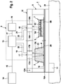
- Fig. 2 shows in a highly simplified schematic representation of the part of the housing 24 of the blood treatment device to which a fastening unit 7 for fixing the functional unit 1 is located.
- Fig. 2 shows only the essential components of the invention of the functional unit 1 and the fastening unit 7.
- Fig. 2 shows a section of the functional unit 1.
- the substituate channel 4 and the hydrophobic filter 5 can be seen with the hydrophobic membrane 5A.
- the remaining chambers and channels are not shown for the sake of clarity.
- the hydrophobic filter 5 comprises a chamber 5B in the housing body 2, which has an opening 5C at the top.
- the opening 5C of the chamber 5B is sealed with the hydrophobic membrane 5A.
- the housing body 2 Above the hydrophobic membrane 5C, the housing body 2 is formed as a support structure, so that the hydrophobic membrane is fixed in the housing body.
- the chamber 5B of the hydrophobic filter 5 is filled with blood.
- the attachment unit 7 of the blood treatment device has a machine-side attachment part 9, which is designed as a housing open on one side for receiving the functional unit 1.
- the functional unit 1 When performing the blood treatment, the functional unit 1 is inserted into the fastening part 9, wherein the underside of the functional unit 1 rests against a contact surface 10 of the fastening part 9.
- the fastening unit 7 has a suction unit 11, which generates a negative pressure on the contact surface 10, so that the functional unit 1 is sucked against the contact surface 10.
- the fastening unit 7 has a cover 12, which is pivotally mounted about an axis 12 A on the mounting part 9. To insert the functional unit, the cover part 12 is opened and closed for operation of the blood treatment device.
- the monitoring unit 8 for checking the functionality and / or the operating state of the functional unit 1 will be described below.
- the monitoring unit 8 has a computing and evaluation unit 13, which may also be part of the central control unit 14 of the blood treatment device.
- the computing and evaluation unit 13 is connected via a data line 15 to the central control unit 14, so that the computing and evaluation unit 13 can receive signals that signal the operating state of the blood treatment device. With the computing and evaluation unit 13 is via a data line 17, an alarm unit 16th connected.
- the monitoring unit 8 has a first transmitting and receiving unit 17 and a second transmitting and receiving unit 18, which emit or receive light.
- the first and second transmitting and receiving units 17, 18 each have a light transmitter 17A, 18A and a light receiver 17B, 18B.
- the light transmitters and light receivers can be light emitting diodes (LED).
- the light emitting diodes of the light emitters preferably emit light having a wavelength corresponding to the absorption maximum of hemoglobin. This results in a maximum sensitivity of the monitoring unit 8 for the detection of blood.
- the light emitter and light receiver 17A, 17B of the first transmitting and receiving unit 17 is arranged on the covering part 12 of the fixing unit 7 above the substituate channel 4, while the light emitter and light receiver 18A, 18B of the second transmitting and receiving unit 18 above the hydrophobic membrane 5A of the hydrophobic filter 5 is disposed in the cover 12.
- the light emitter 17A and the light receiver 17B of the first transmitting and receiving unit 17 are arranged such that the entire light of the light emitter 17A is reflected on the abutment surface 10 of the mounting part 9 and strikes the light receiver 17B.
- the contact surface 10 of the fastening part 9 is covered with a flexible material, for example a plastic mat 10A, against which the functional unit 1 rests.
- the plastic mat 10A is designed such that the light rays are reflected.
- the flexible material may be provided with a reflective coating.
- the light emitter 18A and the light receiver 18B of the second transmitting and receiving unit 18 are arranged above the hydrophobic filter 5 such that the beams of the light emitter 18A are reflected by the hydrophobic membrane 5A and strike the light receiver 18B.
- the arithmetic and evaluation unit 13 receives the signals of the light emitter and receiver 17A, 17B; 18A, 18B via data lines 19, 20, 21, 22.
- the computing and evaluation unit 13 is designed such that on the basis of a weakening of the intensity of the reflected light on a faulty and / or a specific operating state of the functional unit can be in particular closed on a blood leak.
- the computing and evaluation unit 13 can detect a blood leakage, for example, based on a measurement based on Lambert's law. Such optical measuring methods belong to the state of the art.
- the arithmetic and evaluation unit 13 If blood should enter the substituate in a malfunctioning functional unit 1, the light of the light emitter 17A is absorbed by the hemoglobin in the substituate, so that the intensity of the light is attenuated. If the arithmetic and evaluation unit 13 has detected such an accident, the arithmetic and evaluation unit 13 generates an alarm signal that the alarm unit 16 receives via the data line 17. In addition, the computing and evaluation unit 13 generates a control signal, which receives the central control unit 14 of the blood treatment device via the data line 15, so that the control unit 15 can make an intervention in the machine control.
- the hydrophobic membrane 5A of the hydrophobic filter 5 should be defective, blood enters the membrane, causing the membrane to turn red. As a result, the intensity of the reflected light which the light receiver 18B receives changes, so that the arithmetic and evaluation unit 13 again generates an alarm and control signal for the alarm or control unit 16, 14.
- the monitoring unit 8 thus allows monitoring of all areas of the functional unit where leaks may occur. For this purpose, the monitoring unit can still have further transmitting and receiving units.
- the monitoring unit 8 also checks the operating state of the functional unit.
- the functional unit 1 having the transparent case body 2 is inserted in the fixing unit 7, the intensity of the reflected light changes.
- the arithmetic and evaluation unit 13 recognizes on the basis of the signal level of the light receiver 17B, for example the first transmitting and receiving unit 17, whether the functional unit is inserted by the computing and evaluation unit 13 the measured Compares signal level with a given reference level. This reference level can be determined by calibration measurements and stored in a memory of the arithmetic and evaluation unit 13.
- the arithmetic and evaluation unit 13 can detect whether the substituate channel 4 is filled with substituate.
- the filling of the Substituatkanals with substituate leads to an absorption of the light again.
- a further reference level can be set, which is stored in the memory of the arithmetic and evaluation unit 13. It is also possible to detect the level when appropriate reference levels are set.
- the monitoring unit 8 can be tested and / or measured.
- the arithmetic and evaluation unit 13 receive the control signals of the central control unit 14, which signal the operating state of the blood treatment device.
- the safety of the blood treatment is increased by the fact that the individual operating states of the blood treatment device in the arithmetic and evaluation unit 13 are compared with the operating state of the functional unit 1.
- a plausibility check can take place. For example, it can be checked with the computer and evaluation unit 13 as to whether the control unit 14 can start the blood treatment, which should only be the case when the functional unit 1 is located in the fastening unit 7.
- the control unit 14 sets the blood treatment device only in motion when it has received from the computing and evaluation unit 13, the corresponding control signal, which signals that the functional unit is properly inserted into the mounting unit.
Landscapes
- Health & Medical Sciences (AREA)
- Heart & Thoracic Surgery (AREA)
- Vascular Medicine (AREA)
- Life Sciences & Earth Sciences (AREA)
- General Health & Medical Sciences (AREA)
- Public Health (AREA)
- Biomedical Technology (AREA)
- Hematology (AREA)
- Engineering & Computer Science (AREA)
- Animal Behavior & Ethology (AREA)
- Anesthesiology (AREA)
- Veterinary Medicine (AREA)
- Cardiology (AREA)
- Urology & Nephrology (AREA)
- Physics & Mathematics (AREA)
- General Physics & Mathematics (AREA)
- Emergency Medicine (AREA)
- Emergency Management (AREA)
- Business, Economics & Management (AREA)
- External Artificial Organs (AREA)
- Chemical & Material Sciences (AREA)
- Dispersion Chemistry (AREA)
- Analytical Chemistry (AREA)
- Biochemistry (AREA)
- Immunology (AREA)
- Pathology (AREA)
Description
- Die Erfindung betrifft eine Blutbehandlungsvorrichtung mit einer Befestigungseinheit zur Befestigung einer zur einmaligen Verwendung bestimmten Funktionseinheit zur Durchführung der Blutbehandlung und eine Überwachungseinheit zur Überprüfung der Funktionsfähigkeit und/oder des Betriebszustandes der Funktionseinheit. Darüber hinaus betrifft die Erfindung ein Verfahren zum Überprüfen der Funktionsfähigkeit und/oder des Betriebszustandes einer Funktionseinheit, die zur Durchführung einer Blutbehandlung an einer Befestigungseinheit einer Blutbehandlungsvorrichtung befestigt wird.
- Die bekannten Blutbehandlungsvorrichtungen verfügen über einen extrakorporalen Blutkreislauf und ein Dialysierflüssigkeitssystem. Es sind Blutbehandlungsvorrichtungen bekannt, bei denen Teile des extrakorporalen Blutkreislaufs und des Dialysierflüssigkeitssystems Bestandteil einer zur einmaligen Verwendung bestimmten Funktionseinheit (Disposable) sind. Diese Blutbehandlungsvorrichtungen weisen eine Befestigungseinheit auf, an der zur Durchführung der Blutbehandlung die Funktionseinheit befestigt wird.
- Die
DE 10 2009 018 664 A1 beschreibt eine externe Funktionseinheit für eine extrakorporale Blutbehandlungsvorrichtung. Die Funktionseinheit weist einen transparenten Gehäusekörper auf, in dem Kanäle und Kammern für Blut und Dialysierflüssigkeit ausgebildet sind. Die Zufuhr von Blut und Dialysierflüssigkeit erfolgt über Schlauchleitungen, die an Ein- und Auslässen des Gehäusekörpers angeschlossen sind. Die bekannten Funktionseinheiten werden auch als Kassetten bezeichnet. - Aus der
DE 10 2009 012 633 A1 ist eine Befestigungseinheit zur Befestigung einer externen Funktionseinheit bekannt. Die Befestigungseinheit verfügt über einen feststehenden Befestigungsteil und einen schwenkbaren Befestigungsteil, wobei die Funktionseinheit zwischen dem feststehenden und schwenkbaren Befestigungsteil klemmend gehalten wird. - Die
WO 2010/066441 A1 beschreibt eine Befestigungseinheit für eine Funktionseinheit einer extrakorporalen Blutbehandlungsvorrichtung, bei der die Funktionseinheit durch Erzeugung eines Unterdrucks an einer Anlagefläche der Befestigungseinheit gehalten wird. - Bei der Durchführung einer extrakorporalen Blutbehandlung besteht grundsätzlich das Risiko, dass Blut des Patienten aus dem extrakorporalen Blutkreislauf in das Dialysierflüssigkeitssystem gelangt. Dies ist bei einer Ruptur der semipermeablen Membran des Dialysators möglich. Daher wird bei den bekannten Blutbehandlungsvorrichtungen der Eintritt von Blut in das Flüssigkeitssystem überwacht. Die Erkennung von Blut (Hämoglobin) im Flüssigkeitssystem erfolgt nach dem Stand der Technik mittels eines fotometrischen Messverfahrens, bei dem die Abschwächung der Intensität einer Strahlung beim Durchgang durch die Dialysierflüssigkeit infolge des Eintritts von Blut erkannt wird. Ein spektroskopischer Blutleckdetektor ist beispielsweise aus der
DE 10 2006 029 899 B4 bekannt. - Bei der Verwendung einer externen Funktionseinheit zur Durchführung einer Blutbehandlung besteht das Risiko des Eintritts von Blut in die Dialysierflüssigkeit oder das Substituat, wenn an Verbundstellen des Gehäusekörpers Undichtigkeiten auftreten. Beispielsweise können zwischen benachbarten Kammern und Kanälen des Gehäusekörpers Leckagen auftreten.
- Aus der
EP 0 319 279 A1 ist eine Behandlungsvorrichtung mit einer Befestigungseinheit zur Befestigung einer zur einmaligen Verwendung bestimmten Funktionseinheit und einer Überwachungseinheit zur Überprüfung der Funktionsfähigkeit oder des Betriebszustandes der Funktionseinheit bekannt. Die Behandlungsvorrichtung verfügt über ein optisches Sensormodul, das eine Ausnehmung aufweist, in die aber nur der rückwärtige Teil der Funktionseinheit eingesetzt ist. Am Boden des optischen Sensormoduls befinden sich ein Lichtsender und Lichtempfänger. Die Überwachungseinheit weist eine Auswerteeinheit auf, die derart konfiguriert ist, dass aus der Intensität des auf die Funktionseinheit fallenden Lichts und des reflektierten Lichts auf einen fehlerhaften Zustand oder einen bestimmten Betriebszustand der Funktionseinheit geschlossen werden kann. - Die
WO 2010/100989 A2 beschreibt eine zur einmaligen Verwendung bestimmte Funktionseinheit zusammen mit einer Sensorik zur Überprüfung deren Funktionsfähigkeit, Die Sensorik umfasst eine Lichtquelle und eine Kamera, die auf beiden Seiten der Funktionseinheit angeordnet sind. - Aus der
WO 2010/102790 A2 ist eine Aufnahmeeinheit für eine Funktionseinheit (Disposable-Kassette) bekannt, die einen ersten Kontaktabschnitt und einen zweiten Kontaktabschnitt für die Funktionseinheit umfasst. Der erste Kontaktabschnitt ist in einer rahmenförmigen Trägereinrichtung pendelnd oder drehbar gelagert, während der zweite Kontaktabschnitt an dem ersten Kontaktabschnitt in der Art einer Tür beweglich befestigt ist Der zweite Kontaktabschnitt dient der Abdeckung der Disposable-Kassette. DieWO 2010/102790 A2 schlägt vor, in dem ersten Kontaktabschnitt Aktoren oder Sensoren vorzusehen. - Der Erfindung liegt die Aufgabe zu Grunde, die Sicherheit der Blutbehandlung bei der Verwendung einer externen Funktionseinheit zur Durchführung der Blutbehandlung zu erhöhen. Insbesondere liegt der Erfindung die Aufgabe zu Grunde, eine Blutbehandlungsvorrichtung mit einer leicht zu handhabenden Befestigungseinheit zur Befestigung einer Funktionseinheit zur Durchführung der Blutbehandlung zu schaffen, die eine Überprüfung der Funktionsfähigkeit und/oder des Betriebszustandes der Funktionseinheit mit hoher Sicherheit erlaubt.
- Die Lösung dieser Aufgaben erfolgt erfindungsgemäß mit den Merkmalen der unabhängigen Patentansprüche. Die Gegenstände der abhängigen Ansprüche betreffen vorteilhafte Ausführungsformen der Erfindung.
- Die erfindungsgemäße Blutbehandlungsvorrichtung zeichnet sich durch eine Überwachungseinheit zur Überprüfung der Funktionsfähigkeit (Disposable) und/oder des Betriebszustandes der Funktionseinheit aus, die über mindestens einen Lichtsender und mindestens einen Lichtempfänger verfügt. Lichtsender und Lichtempfänger können Bestandteil einer Einrichtung zum Senden und Empfangen von Licht sein. Diese Einrichtung kann beispielsweise als LED-Array ausgebildet sein.
- Lichtsender und Lichtempfänger sind bei der erfindungsgemäßen Überwachungseinheit auf einer Seite der Funktionseinheit angeordnet. Die Anordnung von Lichtsender und Lichtempfänger auf der gleichen Seite bietet den Vorteil, dass sich die Überwachungseinheit ohne größere bauliche Veränderungen in die Befestigungseinheit der Blutbehandlungsvorrichtung integrieren lässt.
- Die Überwachung der Funktionseinheit beruht auf einem optischen Messverfahren, bei dem das an einem Teil der Funktionseinheit oder einem Teil der Befestigungseinheit reflektierte Licht erfasst wird. Die Rechen- und Auswerteinheit ist derart konfiguriert, dass das aus der Intensität des auf die Funktionseinheit fallenden Lichts und des an der Funktionseinheit oder Befestigungseinheit reflektierten Lichts auf einen fehlerhaften Zustand und/oder einen bestimmten Betriebszustand der Funktionseinheit geschlossen wird.
- Wenn beispielsweise Blut von der Blutseite in die Dialysatseite aufgrund einer fehlerhaften Funktionseinheit eintreten sollte, kann der fehlerhafte Zustand mit der Funktionseinheit erkannt werden. Beispielsweise kann erkannt werden, ob Blut aus einer Blutkammer oder einem blutführenden Kanal in eine Dialysierflüssigkeitskammer oder einen Dialysierflüssigkeit oder Substituat führenden Kanal aufgrund einer Leckage in dem Gehäusekörper der Funktionseinheit eingetreten ist. Der Eintritt von Blut lässt sich nach den bekannten Verfahren zum Erkennen von Hämoglobin einfach nachweisen. Darüber hinaus kann erkannt werden, ob in einem Kanal oder einer Kammer der Funktionseinheit sich eine bestimmte Flüssigkeit, insbesondere Blut, Dialysierflüssigkeit oder Substituat befindet oder ob die Kammern oder Kanäle der Funktionseinheit überhaupt mit Flüssigkeit gefüllt sind. Die erfindungsgemäße Blutbehandlungsvorrichtung erlaubt somit nicht nur die Überprüfung der Funktionsfähigkeit, sondern auch des Betriebszustandes der Funktionseinheit.
- Bei der erfindungsgemäßen Blutbehandlungsvorrichtung, die sich durch eine einfache Handhabbarkeit auszeichnet, verfügt die Befestigungseinheit über einen Befestigungsteil und einen Abdeckteil, die derart im Abstand zueinander angeordnet sind, dass die Funktionseinheit zwischen Befestigungsteil und Abdeckteil einsetzbar ist. Der Lichtsender und der Lichtempfänger sind an dem Abdeckteil vorgesehen.
- Bei einer weiteren besonders bevorzugten Ausführungsform weist der Befestigungsteil der Befestigungseinheit eine das Licht des Lichtsenders reflektierende Anlagefläche für die Funktionseinheit auf. Das auf die Funktionseinheit fallende und durch die Funktionseinheit hindurchtretende Licht wird für die optische Reflektionsmessung an der Anlagefläche des Befestigungsteils reflektiert, so dass das Licht auf der gleichen Seite der Funktionseinheit ausgesandt und empfangen werden kann.
- Der Abdeckteil der Befestigungseinheit ist zwischen einer geöffneten und einer geschlossenen Position beweglich an dem Befestigungsteil befestigt, so dass sich die Funktionseinheit einfach in die Befestigungseinheit einsetzen lässt. Vorzugsweise ist der Abdeckteil als eine Tür ausgebildet, die den Aufnahmeraum des Befestigungsteils zur Aufnahme der Funktionseinheit verschließt.
- Der Abdeckteil der Befestigungseinheit kann als Klemmteil ausgebildet sein, so dass die Funktionseinheit zwischen Befestigungsteil und Abdeckteil klemmend befestigt werden kann.
- Eine alternative Ausführungsform sieht vor, dass die Befestigungseinheit eine Saugeinheit zur Erzeugung eines Unterdrucks an dem Befestigungsteil aufweist, so dass die Funktionseinheit an dem Befestigungsteil durch eine Saugkraft befestigt werden kann. Bei dieser Ausführungsform weist die Anlagefläche des Befestigungsteils vorzugsweise ein flexibles Material auf, an dem die Funktionseinheit anliegt. Das flexible Material bildet vorzugsweise eine reflektierende Anlagefläche, an der das Licht reflektiert wird.
- Die Vorteile der Anordnung von Lichtsender und -empfänger in bzw. an dem Abdeckteil liegen bei den bevorzugten Ausführungsformen insbesondere darin, dass sich das Befestigungsteil mit einer Anlagefläche ausbilden lässt, die nicht von Bauteilen des Lichtsenders und -empfängers durchbrochen ist. Insbesondere bei der Ausführungsform mit der ein flexibles Material aufweisenden Anlagefläche sind in dem flexiblen Material keine Öffnungen für den Durchtritt des Lichts erforderlich, die unter dem Gesichtspunkt einer einfachen Reinigung des flexiblen Materials nachteilig wären.
- Darüber hinaus kommen die Vorteile der Erfindung insbesondere bei einer Funktionseinheit zum Tragen, bei der eine Kammer oder ein Kanal eine mit einer hydrophoben Membran verschlossene Öffnung aufweist, d.h. einer Funktionseinheit, in die ein oder mehrere Hydrophobfilter integriert sind. Bei einer derartigen Funktionseinheit erlaubt die Überwachungseinheit nicht nur die Überprüfung der Blut bzw. Dialysierflüssigkeit führenden Kanäle, sondern auch des Hydrophobfilters, durch den im Falle einer Ruptur Blut austreten kann. Zur Überwachung des Hydrophobfilters wird nicht das an der Befestigungseinheit reflektierte Licht, sondern das an einem Teil der Funktionseinheit reflektierte Licht, d.h. das an der hydrophoben Membran reflektierte Licht erfasst. Im Fehlerfall dringt Blut in die rückseitigen Fasern der Membran ein und färbt diese rot, so dass sich die Intensität des reflektierten Lichts ändert, was von der Überwachungseinheit erkannt wird.
- Mit dem Lichtsender und Lichtempfänger der Überwachungseinheit kann auch erkannt werden, ob die Funktionseinheit an der Befestigungseinheit befestigt ist, da der Gehäusekörper der Funktionseinheit Licht absorbiert.
- Für die unterschiedlichen Fälle können verschiedene Kriterien aufgestellt werden, so dass sich in Abhängigkeit von der Abschwächung des reflektierten Lichts auf die Funktionsfähigkeit und/oder den Betriebszustand der Funktionseinheit geschlossen werden kann.
- Im Folgenden wird ein Ausführungsbeispiel der Erfindung unter Bezugnahme auf die Figuren im Einzelnen beschrieben.
- Es zeigen:
- Fig. 1
- eine Funktionseinheit zur Durchführung der Blutbehandlung für eine Blutbehandlungsvorrichtung in der Draufsicht und
- Fig. 2
- die Befestigungseinheit zusammen mit der Funktionseinheit der Blutbehandlungsvorrichtung in stark vereinfachter schematischer Darstellung.
-
Fig. 1 zeigt ein Ausführungsbeispiel einer externen Funktionseinheit (Disposable) für eine extrakorporale Blutbehandlungsvorrichtung, insbesondere eine Hämodialysevorrichtung. Die Funktionseinheit 1 weist einen flachen Gehäusekörper 2 auf, der aus einem für Licht durchlässigen Material besteht. Der Gehäusekörper 2 kann ein transparenter Kunststoffkörper sein. Die Funktionseinheit ist im Einzelnen in derDE 10 2009 018 664 A1 beschrieben, auf die ausdrücklich Bezug genommen wird. Nachfolgend werden die für die Erfindung wesentlichen Komponenten der Funktionseinheit beschrieben. -
Fig. 1 zeigt die Funktionseinheit (1) in der Unteransicht. Der Gehäusekörper 2 der Funktionseinheit 1 weist einen mit muldenförmigen Vertiefungen 23 geformten Gehäuseteil 2A auf, der an der Unterseite mit einer nur teilweise dargestellten Folie 2B unter Bildung einer Mehrzahl von Kammern und Kanälen dicht verschlossen ist. Während des Betriebs der Hämodialysevorrichtung befinden sich in den Kammern und Kanälen Blut oder eine medizinische Flüssigkeit, beispielsweise Dialysierflüssigkeit oder Substituat. - In
Fig. 1 ist eine der Kammern mit dem Bezugszeichen 3 und einer der Kanäle mit dem Bezugszeichen 4 bezeichnet. In der Kammer 3 befindet sich während des Betriebs der Dialysevorrichtung Blut. Der Kanal 4 ist ein Kanal, in dem während des Betriebs der Dialysevorrichtung Substituat strömt. Darüber hinaus verfügt die Funktionseinheit 1 über einen Hydrophobfilter 5, der eine inFig. 1 nur andeutungsweise dargestellte hydrophobe Membran 5A aufweist. Weiterhin verfügt die Funktionseinheit 1 noch über eine inFig. 1 nicht näher bezeichnete Ventilanordnung, die eine Mehrzahl von Ventilen umfasst, mit denen die Flüssigkeitsverbindungen zwischen den einzelnen Kammern und Kanälen hergestellt werden können. - Das Blut und die medizinischen Flüssigkeiten werden über nicht dargestellte Schlauchleitungen zu- bzw. abgeführt, die an Anschlüssen 6A bis 6D des Gehäusekörpers 2 angeschlossen sind. Die nicht dargestellten Schlauchleitungen sind ggf. mit weiteren nicht dargestellten Komponenten Bestandteil der Funktionseinheit 1.
-
Fig. 2 zeigt in stark vereinfachter schematischer Darstellung den Teil des Gehäuses 24 der Blutbehandlungsvorrichtung, an dem sich eine Befestigungseinheit 7 zur Befestigung der Funktionseinheit 1 befindet.Fig. 2 zeigt nur die für die Erfindung wesentlichen Komponenten der Funktionseinheit 1 und der Befestigungseinheit 7. Darüber hinaus ist inFig. 2 eine Überwachungseinheit 8 zum Überprüfen der Funktionsfähigkeit und/oder des Betriebszustandes der Funktionseinheit dargestellt. - Die Funktionseinheit 1 ist in die Befestigungseinheit 7 eingesetzt.
Fig. 2 zeigt einen Schnitt der Funktionseinheit 1. In der Schnittdarstellung ist der Substituatkanal 4 und der Hydrophobfilter 5 mit der hydrophoben Membran 5A zu erkennen. Die übrigen Kammern und Kanäle sind der besseren Übersichtlichkeit halber nicht dargestellt. - Der Hydrophobfilter 5 umfasst eine Kammer 5B in dem Gehäusekörper 2, die an der Oberseite eine Öffnung 5C aufweist. Die Öffnung 5C der Kammer 5B ist mit der hydrophoben Membran 5A dicht verschlossen. Oberhalb der hydrophoben Membran 5C ist der Gehäusekörper 2 als Stützstruktur ausgebildet, so dass die hydrophobe Membran in dem Gehäusekörper fixiert ist. Während des Betriebs der Hämodialysevorrichtung, beispielsweise im Einnadel-Betrieb, ist die Kammer 5B des Hydrophobfilters 5 mit Blut befüllt.
- Die Befestigungseinheit 7 der Blutbehandlungsvorrichtung weist einen maschinenseitigen Befestigungsteil 9 auf, der als ein an einer Seite offenes Gehäuse zur Aufnahme der Funktionseinheit 1 ausgebildet ist.
- Bei der Durchführung der Blutbehandlung wird die Funktionseinheit 1 in den Befestigungsteil 9 eingelegt, wobei die Unterseite der Funktionseinheit 1 an einer Anlagefläche 10 des Befestigungsteils 9 anliegt. Die Befestigungseinheit 7 weist eine Saugeinheit 11 auf, die an der Anlagefläche 10 einen Unterdruck erzeugt, so dass die Funktionseinheit 1 an die Anlagefläche 10 angesaugt wird.
- Darüber hinaus weist die Befestigungseinheit 7 einen Abdeckteil 12 auf, der um eine Achse 12A schwenkbar an dem Befestigungsteil 9 befestigt ist. Zum Einsetzen der Funktionseinheit wird der Abdeckteil 12 geöffnet und zum Betrieb der Blutbehandlungsvorrichtung geschlossen.
- Nachfolgend wird die Überwachungseinheit 8 zur Überprüfung der Funktionsfähigkeit und/oder des Betriebszustandes der Funktionseinheit 1 beschrieben.
- Die Überwachungseinheit 8 weist eine Rechen- und Auswerteinheit 13 auf, die auch Bestandteil der zentralen Steuereinheit 14 der Blutbehandlungsvorrichtung sein kann. Die Rechen- und Auswerteinheit 13 ist über eine Datenleitung 15 mit der zentralen Steuereinheit 14 verbunden, so dass die Rechen- und Auswerteinheit 13 Signale empfangen kann, die den Betriebszustand der Blutbehandlungsvorrichtung signalisieren. Mit der Rechen- und Auswerteinheit 13 ist über eine Datenleitung 17 eine Alarmeinheit 16 verbunden. Darüber hinaus weist die Überwachungseinheit 8 eine erste Sende- und Empfangseinheit 17 und eine zweite Sende- und Empfangseinheit 18 auf, die Licht aussenden bzw. empfangen.
- Die erste und zweite Sende- und Empfangseinheit 17, 18 weisen jeweils einen Lichtsender 17A, 18A und einen Lichtempfänger 17B, 18B auf. Die Lichtsender und Lichtempfänger können Leuchtdioden sein (LED). Die Leuchtdioden der Lichtsender senden vorzugsweise Licht mit einer Wellenlänge aus, die dem Absorptionsmaximum von Hämoglobin entspricht. Dadurch ergibt sich eine maximale Empfindlichkeit der Überwachungseinheit 8 für die Erkennung von Blut.
- Der Lichtsender und Lichtempfänger 17A, 17B der ersten Sende- und Empfangseinheit 17 ist an dem Abdeckteil 12 der Befestigungseinheit 7 oberhalb des Substituatkanals 4 angeordnet, während der Lichtsender und Lichtempfänger 18A, 18B der zweiten Sende- und Empfangseinheit 18 oberhalb der hydrophoben Membran 5A des Hydrophobfilters 5 in dem Abdeckteil 12 angeordnet ist.
- Der Lichtsender 17A und der Lichtempfänger 17B der ersten Sende- und Empfangseinheit 17 sind derart angeordnet, dass das gesamte Licht des Lichtsenders 17A an der Anlagefläche 10 des Befestigungsteils 9 reflektiert wird und auf den Lichtempfänger 17B trifft. Bei einer bevorzugten Ausführungsform ist die Anlagefläche 10 des Befestigungsteils 9 mit einem flexiblen Material, beispielsweise einer Kunststoffmatte 10A belegt, an der die Funktionseinheit 1 anliegt. Die Kunststoffmatte 10A ist dabei derart beschaffen, dass die Lichtstrahlen reflektiert werden. Beispielsweise kann das flexible Material mit einer reflektierenden Beschichtung versehen sein.
- Der Lichtsender 18A und der Lichtempfänger 18B der zweiten Sende- und Empfangseinheit 18 sind oberhalb des hydrophoben Filters 5 derart angeordnet, dass die Strahlen des Lichtsenders 18A von der hydrophoben Membran 5A reflektiert werden und auf den Lichtempfänger 18B treffen.
- Die Rechen- und Auswerteinheit 13 empfängt die Signale der Lichtsender und -empfänger 17A, 17B; 18A, 18B über Datenleitungen 19, 20, 21, 22. Die Rechen- und Auswerteinheit 13 ist derart ausgebildet, dass auf der Grundlage einer Abschwächung der Intensität des reflektierten Lichts auf einen fehlerhaften und/oder einen bestimmten Betriebszustand der Funktionseinheit geschlossen werden kann, insbesondere auf eine Blutleckage geschlossen wird. Die Rechen- und Auswerteinheit 13 kann eine Blutleckage beispielsweise auf der Grundlage einer Messung erkennen, die auf dem Lambertschen Gesetz basiert. Derartige optische Messverfahren gehören zum Stand der Technik.
- Wenn bei einer fehlerhaften Funktionseinheit 1 Blut in das Substituat gelangen sollte, wird das Licht des Lichtsenders 17A durch das Hämoglobin im Substituat absorbiert, so dass die Intensität des Lichts abgeschwächt wird. Wenn die Rechen- und Auswerteinheit 13 einen derartigen Störfall erkannt hat, erzeugt die Rechen- und Auswerteinheit 13 ein Alarmsignal, dass die Alarmeinheit 16 über die Datenleitung 17 empfängt. Darüber hinaus erzeugt die Rechen- und Auswerteinheit 13 ein Steuersignal, das die zentrale Steuereinheit 14 der Blutbehandlungsvorrichtung über die Datenleitung 15 empfängt, so dass die Steuereinheit 15 einen Eingriff in die Maschinensteuerung vornehmen kann.
- Wenn die hydrophobe Membran 5A des Hydrophobfilters 5 defekt sein sollte, tritt Blut in die Membran ein, so dass sich die Membran rot färbt. Dadurch ändert sich die Intensität des reflektierten Lichts, das der Lichtempfänger 18B empfängt, so dass die Rechen- und Auswerteinheit 13 wieder ein Alarm- und Steuersignal für die Alarm- bzw. Steuereinheit 16, 14 erzeugt. Die Überwachungseinheit 8 erlaubt somit die Überwachung sämtlicher Bereiche der Funktionseinheit, an denen Leckagen auftreten können. Hierzu kann die Überwachungseinheit noch über weitere Sende- und Empfangseinheiten verfügen.
- Neben der Funktionsfähigkeit überprüft die Überwachungseinheit 8 auch den Betriebszustand der Funktionseinheit. Wenn die Funktionseinheit 1 mit dem transparenten Gehäusekörper 2 in die Befestigungseinheit 7 eingelegt ist, ändert sich die Intensität des reflektierten Lichts. Die Rechen- und Auswerteinheit13 erkennt anhand des Signalpegels des Lichtempfängers 17B beispielsweise der ersten Sende- und Empfangseinheit 17, ob die Funktionseinheit eingelegt ist, indem die Rechen- und Auswerteinheit 13 den gemessenen Signalpegel mit einem vorgegebenen Referenzpegel vergleicht. Dieser Referenzpegel kann durch Kalibriermessungen festgelegt und in einem Speicher der Rechen- und Auswerteinheit 13 gespeichert werden.
- Darüber hinaus kann die Rechen- und Auswerteinheit 13 erkennen, ob der Substituatkanal 4 mit Substituat gefüllt ist. Die Befüllung des Substituatkanals mit Substituat führt wieder zu einer Absorption des Lichts. Für die Messung kann ein weiterer Referenzpegel festgelegt werden, der in dem Speicher der Rechen- und Auswerteinheit 13 gespeichert wird. Es ist auch möglich, den Füllstand zu detektieren, wenn entsprechende Referenzpegel festgelegt werden.
- Durch die Signalabfolge beim Einlegen, Ansaugen und Befüllen der Funktionseinheit 1 kann die Überwachungseinheit 8 getestet und/oder eingemessen werden. Hierzu kann die Rechen- und Auswerteinheit 13 die Steuersignale der zentralen Steuereinheit 14 empfangen, die den Betriebszustand der Blutbehandlungsvorrichtung signalisieren.
- Bei einer besonders bevorzugten Ausführungsform wird die Sicherheit der Blutbehandlung dadurch erhöht, dass die einzelnen Betriebszustände der Blutbehandlungsvorrichtung in der Rechen- und Auswerteinheit 13 mit dem Betriebszustand der Funktionseinheit 1 verglichen werden. Dabei kann eine Plausibilitätsprüfung stattfinden. Beispielsweise kann mit der Rechen- uns Auswerteinheit 13 überprüft werden, ob die Steuereinheit 14 die Blutbehandlung in Gang setzen kann, was nur dann der Fall sein soll, wenn sich die Funktionseinheit 1 in der Befestigungseinheit 7 befindet. Die Steuereinheit 14 setzt die Blutbehandlungsvorrichtung nur dann in Gang, wenn sie von der Rechen- und Auswerteinheit 13 das entsprechende Steuersignal empfangen hat, das signalisiert, dass die Funktionseinheit ordnungsgemäß in die Befestigungseinheit eingesetzt ist.
Claims (16)
- Blutbehandlungsvorrichtung mit einer Befestigungseinheit (7) zur Befestigung einer zur einmaligen Verwendung bestimmten Funktionseinheit (1) zur Durchführung der Blutbehandlung und einer Überwachungseinheit (8) zur Überprüfung der Funktionsfähigkeit und/oder des Betriebszustandes der Funktionseinheit, wobei die Überwachungseinheit (8) mindestens einen Lichtsender (17A, 18A) und mindestens einen Lichtempfänger (17B, 18B) aufweist, die derart angeordnet sind, dass das von dem Lichtsender (17A, 18A) ausgesandte Licht auf eine Seite der Funktionseinheit (1) fällt und das an einem Teil der Funktionseinheit oder einem Teil der Befestigungseinheit (7) reflektierte Licht auf den Lichtempfänger (17B, 18B) fällt, und die Überwachungseinheit (8) eine Rechen- und Auswerteinheit (13) aufweist, die derart konfiguriert ist, dass aus der Intensität des auf die Funktionseinheit (1) fallenden Lichts und des an der Funktionseinheit oder Befestigungseinheit (7) reflektierten Lichts auf einen fehlerhaften Zustand und/oder einen bestimmten Betriebszustand der Funktionseinheit (1) geschlossen wird,
dadurch gekennzeichnet, dass
die Befestigungseinheit (7) einen Befestigungsteil (9) und einen Abdeckteil (12) aufweist, wobei der Abdeckteil (12) zwischen einer geöffneten Position und einer geschlossenen Position beweglich an dem Befestigungsteil (9) befestigt ist und Befestigungsteil (9) und Abdeckteil (12) derart im Abstand zueinander angeordnet sind, dass die Funktionseinheit (1) zwischen Befestigungsteil (9) und Abdeckteil (12) einsetzbar ist, und
der Lichtsender (17A, 18A) und der Lichtempfänger (17B, 18B) in oder an dem beweglichen Abdeckteil (12) vorgesehen sind. - Blutbehandlungsvorrichtung nach Anspruch 1, dadurch gekennzeichnet, dass der Befestigungsteil (9) der Befestigungseinheit (7) eine das Licht des Lichtsenders (17A, 18A) reflektierende Anlagefläche (10) für die Funktionseinheit (1) aufweist.
- Blutbehandlungsvorrichtung nach Anspruch 2, dadurch gekennzeichnet, dass die Anlagefläche (10) des Befestigungsteils (9) ein flexibles Material (10A) aufweist.
- Blutbehandlungsvorrichtung nach einem der Ansprüche 1 bis 3, dadurch gekennzeichnet, dass der Abdeckteil (12) der Befestigungseinheit (7) als Klemmteil ausgebildet ist, so dass die Funktionseinheit (1) zwischen Befestigungsteil (9) und Abdeckteil (12) klemmend befestigbar ist.
- Blutbehandlungsvorrichtung nach einem der Ansprüche 1 bis 3, dadurch gekennzeichnet, dass die Befestigungseinheit (7) eine Saugeinheit (11) zur Erzeugung eines Unterdrucks an dem Befestigungsteil (9) aufweist, so dass die Funktionseinheit (1) an dem Befestigungsteil (9) durch eine Saugkraft befestigbar ist.
- Blutbehandlungsvorrichtung nach einem der Ansprüche 1 bis 5, dadurch gekennzeichnet, dass die Rechen- und Auswerteinheit (13) der Überwachungseinheit (8) derart konfiguriert ist, dass auf der Grundlage der Abschwächung der Intensität des Lichts darauf geschlossen wird, dass eine Funktionseinheit (1) an der Befestigungseinheit (7) befestigt ist.
- Blutbehandlungsvorrichtung nach einem der Ansprüche 1 bis 6, dadurch gekennzeichnet, dass die Rechen- und Auswerteinheit (13) der Überwachungseinheit (8) derart konfiguriert ist, dass auf der Grundlage der Abschwächung der Intensität des Lichts darauf geschlossen wird, dass eine Kammer (3) oder ein Kanal (4) der Funktionseinheit (1) mit einer Flüssigkeit, insbesondere Dialysierflüssigkeit oder Substituat, befüllt ist.
- Blutbehandlungsvorrichtung nach Anspruch 7, dadurch gekennzeichnet, dass die Rechen- und Auswerteinheit (13) der Überwachungseinheit (8) derart konfiguriert ist, dass ein Steuersignal erzeugt wird, wenn die Rechen- und Auswerteinheit (13) erkannt hat, dass die Kammer (3) und/oder der Kanal (4) der Funktionseinheit (1) mit einer Flüssigkeit, insbesondere Dialysierflüssigkeit oder Substituat, befüllt ist, wobei die Blutbehandlungsvorrichtung eine Steuereinheit (14) aufweist, die das Steuersignal der Rechen- und Auswerteinheit (13) empfängt.
- Blutbehandlungsvorrichtung nach Anspruch 7 oder 8, dadurch gekennzeichnet, dass die Rechen- und Auswerteinheit (13) der Überwachungseinheit (8) derart konfiguriert ist, dass auf der Grundlage der Abschwächung der Intensität des Lichts darauf geschlossen wird, dass die Flüssigkeit, mit der die Kammer (3) oder der Kanal (4) befüllt ist, Hämoglobin enthält.
- Blutbehandlungsvorrichtung nach Anspruch 9, dadurch gekennzeichnet, dass die Rechen- und Auswerteinheit (13) der Überwachungseinheit (8) derart konfiguriert ist, dass ein Alarmsignal erzeugt wird, wenn die Rechen- und Auswerteinheit (13) erkannt hat, dass die Flüssigkeit, mit der die Kammer oder der Kanal befüllt ist, Hämoglobin enthält, wobei die Blutbehandlungsvorrichtung eine Alarmeinheit (16) aufweist, die das Alarmsignal der Rechen- und Auswerteinheit (13) empfängt.
- Anordnung mit einer Blutbehandlungsvorrichtung nach einem der Ansprüche 1 bis 10 und einer zur einmaligen Verwendung bestimmten Funktionseinheit (1) zur Durchführung der Blutbehandlung.
- Anordnung nach Anspruch 11, dadurch gekennzeichnet, dass die Funktionseinheit (1) einen für Licht durchlässigen Gehäusekörper (2) aufweist, in dem mindestens eine Kammer (3; 5B) zur Aufnahme einer Flüssigkeit und/oder mindestens ein Kanal (4) zum Leiten einer Flüssigkeit ausgebildet sind, wobei der Lichtsender (17A, 18A) und der Lichtempfänger (17B, 18B) auf einer Seite des Gehäusekörpers (2) derart angeordnet sind, dass das von dem Lichtsender (17A, 18A) ausgesandte Licht auf eine Kammer (3; 5B) und/oder einen Kanal (4) der an der Befestigungseinheit (7) befestigten Funktionseinheit (1) fällt.
- Anordnung nach Anspruch 12, dadurch gekennzeichnet, dass der Gehäusekörper (2) der Funktionseinheit (1) einen mit muldenförmigen Vertiefungen (23) geformten Gehäuseteil (2A) aufweist, der mit einem flachen Gehäuseteil (2B) flüssigkeitsdicht verschlossen ist.
- Anordnung nach Anspruch 13, dadurch gekennzeichnet, dass der flache Gehäuseteil (2B) eine Folie ist, die mit dem mit muldenförmigen Vertiefungen (23) geformten Gehäuseteil (2A) verbunden ist.
- Anordnung nach einem der Ansprüche 12 bis 14, dadurch gekennzeichnet, dass die Kammer (5B) oder der Kanal (4) eine mit einer hydrophoben Membran (5A) verschlossene Öffnung (5C) aufweist, wobei Lichtsender (17A, 18A) und Lichtempfänger (17B, 18B) derart angeordnet sind, dass das von dem Lichtsender (17A, 18A) ausgesandte Licht auf die hydrophobe Membran (5A) der Kammer (5B) fällt und das von der hydrophoben Membran (5A) reflektierte Licht auf den Lichtempfänger (17B, 18B) fällt.
- Anordnung nach Anspruch 15, dadurch gekennzeichnet, dass die Rechen- und Auswerteinheit(13) der Überwachungseinheit (8) derart konfiguriert ist, dass auf der Grundlage der Abschwächung der Intensität des Lichts darauf geschlossen wird, dass die hydrophobe Membran (5A) defekt ist.
Applications Claiming Priority (2)
| Application Number | Priority Date | Filing Date | Title |
|---|---|---|---|
| DE102014011695.6A DE102014011695A1 (de) | 2014-08-07 | 2014-08-07 | Blutbehandlungsvorrichtung mit einer Funktionseinheit zur Durchführung der Blutbehandlung und Verfahren zur Überprüfung der Funktionsfähigkeit und/oder des Betriebszustandes der Funktionseinheit |
| PCT/EP2015/066687 WO2016020191A1 (de) | 2014-08-07 | 2015-07-21 | Blutbehandlungsvorrichtung mit einer funktionseinheit zur durchführung der blutbehandlung und verfahren zur überprüfung der funktionsfähigkeit und/oder des betriebszustandes der funktionseinheit |
Publications (2)
| Publication Number | Publication Date |
|---|---|
| EP3177337A1 EP3177337A1 (de) | 2017-06-14 |
| EP3177337B1 true EP3177337B1 (de) | 2019-07-10 |
Family
ID=53716487
Family Applications (1)
| Application Number | Title | Priority Date | Filing Date |
|---|---|---|---|
| EP15739592.2A Active EP3177337B1 (de) | 2014-08-07 | 2015-07-21 | Blutbehandlungsvorrichtung mit einer funktionseinheit zur durchführung der blutbehandlung und zur überprüfung der funktionsfähigkeit und/oder des betriebszustandes der funktionseinheit |
Country Status (4)
| Country | Link |
|---|---|
| US (1) | US10471198B2 (de) |
| EP (1) | EP3177337B1 (de) |
| DE (1) | DE102014011695A1 (de) |
| WO (1) | WO2016020191A1 (de) |
Families Citing this family (5)
| Publication number | Priority date | Publication date | Assignee | Title |
|---|---|---|---|---|
| WO2016057982A1 (en) | 2014-10-10 | 2016-04-14 | Nxstage Medical, Inc. | Flow balancing devices, methods, and systems |
| DE102016109196A1 (de) * | 2016-05-19 | 2017-11-23 | Fresenius Medical Care Deutschland Gmbh | Medizinische Einrichtung mit optional hydrophober Filtermembran und vorderseitiger Stützstruktur hierfür |
| US10898635B2 (en) | 2016-07-18 | 2021-01-26 | Nxstage Medical, Inc. | Flow balancing devices, methods, and systems |
| EP3506962B1 (de) | 2016-08-30 | 2023-11-22 | NxStage Medical, Inc. | Parameterüberwachung in medizinischen behandlungssystemen |
| CA3138773A1 (en) | 2019-05-23 | 2020-11-26 | Nxstage Medical, Inc. | Flow synchronization devices, methods and systems |
Family Cites Families (17)
| Publication number | Priority date | Publication date | Assignee | Title |
|---|---|---|---|---|
| US4166961A (en) * | 1978-03-22 | 1979-09-04 | Hoechst Aktiengesellschaft | Method and apparatus for detecting a blood leak in a hemodialysis system |
| US4818190A (en) * | 1987-12-01 | 1989-04-04 | Pacesetter Infusion, Ltd. | Cassette loading and latching apparatus for a medication infusion system |
| US5601080A (en) * | 1994-12-28 | 1997-02-11 | Coretech Medical Technologies Corporation | Spectrophotometric blood analysis |
| SE9804142D0 (sv) * | 1998-11-30 | 1998-11-30 | Gambro Ab | Method and device for providing a signal |
| US8033115B2 (en) * | 2006-01-05 | 2011-10-11 | General Electric Company | Water injection manifold pressure relief vent |
| DE102006029899B4 (de) * | 2006-06-29 | 2009-06-04 | Fresenius Medical Care Deutschland Gmbh | Spektroskopischer Detektor und Verfahren zur Bestimmung von Blut und biologischen Markersubstanzen in Flüssigkeiten |
| US7998115B2 (en) | 2007-02-15 | 2011-08-16 | Baxter International Inc. | Dialysis system having optical flowrate detection |
| US8105487B2 (en) * | 2007-09-25 | 2012-01-31 | Fresenius Medical Care Holdings, Inc. | Manifolds for use in conducting dialysis |
| KR101275037B1 (ko) | 2008-12-12 | 2013-06-17 | 프레제니우스 메디칼 케어 도이칠란드 게엠베하 | 약액 처리 장치 및 약액 처리 장치의 누설 방지 검사 방법 |
| US8663463B2 (en) * | 2009-02-18 | 2014-03-04 | Fresenius Medical Care Holdings, Inc. | Extracorporeal fluid circuit and related components |
| DE102009012633A1 (de) | 2009-03-10 | 2010-09-23 | Fresenius Medical Care Deutschland Gmbh | Vorrichtung zum Verbinden einer externen Funktionseinrichtung mit einer Anordnung, Anordnung aufweisend eine solche Vorrichtung und Verfahren zum Verbinden |
| CN101832225B (zh) * | 2009-03-12 | 2014-06-11 | 严强 | 升力型垂直轴风力发电机风轮结构 |
| DE102009018664A1 (de) | 2009-04-23 | 2010-10-28 | Fresenius Medical Care Deutschland Gmbh | Externe Funktionseinrichtung, Blutbehandlungsvorrichtung zum Aufnehmen einer erfindungsgemäßen externen Funktionseinrichtung, sowie Verfahren |
| JP5711214B2 (ja) * | 2009-04-23 | 2015-04-30 | フレゼニウス メディカル ケア ドイッチェランド ゲゼルシャフト ミット ベシュレンクテル ハフツング | 外部機能手段、本発明に係る外部機能手段を受けるための血液処理機器、および、方法 |
| SG195155A1 (en) | 2011-05-24 | 2013-12-30 | Deka Products Lp | Blood treatment systems and methods |
| US8803090B2 (en) * | 2012-11-09 | 2014-08-12 | Fenwal, Inc. | Citrate detector for blood processing system |
| US9927105B2 (en) * | 2015-07-22 | 2018-03-27 | Usa Products Group | Lift assembly and related method |
-
2014
- 2014-08-07 DE DE102014011695.6A patent/DE102014011695A1/de not_active Withdrawn
-
2015
- 2015-07-21 US US15/501,861 patent/US10471198B2/en active Active
- 2015-07-21 WO PCT/EP2015/066687 patent/WO2016020191A1/de not_active Ceased
- 2015-07-21 EP EP15739592.2A patent/EP3177337B1/de active Active
Non-Patent Citations (1)
| Title |
|---|
| None * |
Also Published As
| Publication number | Publication date |
|---|---|
| US20170232174A1 (en) | 2017-08-17 |
| EP3177337A1 (de) | 2017-06-14 |
| US10471198B2 (en) | 2019-11-12 |
| WO2016020191A1 (de) | 2016-02-11 |
| DE102014011695A1 (de) | 2016-02-11 |
Similar Documents
| Publication | Publication Date | Title |
|---|---|---|
| EP2308525B1 (de) | Vorrichtung zur Behandlung einer medizinischen Flüssigkeit | |
| WO2016020191A1 (de) | Blutbehandlungsvorrichtung mit einer funktionseinheit zur durchführung der blutbehandlung und verfahren zur überprüfung der funktionsfähigkeit und/oder des betriebszustandes der funktionseinheit | |
| EP2919829B1 (de) | Vorrichtung zur identifizierung einer dialysatorvorrichtung oder einer komponente derselben, und hierfür verwendbare sensorvorrichtung | |
| DE102006029899B4 (de) | Spektroskopischer Detektor und Verfahren zur Bestimmung von Blut und biologischen Markersubstanzen in Flüssigkeiten | |
| EP2806915B1 (de) | System zur erfassung eines zustands einer dialysatorvorrichtung, und hierfür verwendbare sensorvorrichtung | |
| EP0980686B1 (de) | Multifunktionssensor | |
| DE112006003853B4 (de) | Extrakorporale Blutbehandlungsvorrichtung mit Pumpenabgleich | |
| EP2416699B1 (de) | Vorrichtung und verfahren zur messung eines blutbestandteils im blut für eine extrakorporale blutbehandlungsvorrichtung | |
| DE102009001901A1 (de) | Blutbehandlungsvorrichtung | |
| EP3063541B1 (de) | Verfahren und vorrichtung zur erfassung der hämolyse oder zur bestimmung eines den einfluss der hämolyse auf eine messung des hämatokrits korrigierenden korrekturfaktors | |
| DE202013011936U1 (de) | Vorrichtung zur Erkennung von Blut oder eines Blutbestandteils in einer Flüssigkeit | |
| DE102017000226A1 (de) | Vorrichtung und Verfahren zur Erkennung von Blut oder eines Blutbestandteils oder der Bestimmung der Konzentration von Blut oder eines Blutbestandteils in einer Flüssigkeit | |
| DE102009051993A1 (de) | Einrichtung zur Überwachung eines Gefässzugangs | |
| EP4448041A1 (de) | Blutbehandlungsmaschine zur extrakorporalen blutbehandlung und system zur erkennung von blut oder von blutbestandteilen in einer schlauchleitung | |
| DE102009005402B4 (de) | Verfahren zum Bestimmen der Konzentration von Blutbestandteilen in einer mit Blut gefüllten Schlauchleitung | |
| DE102017113398A1 (de) | Tür einer medizinischen Sensorvorrichtung, medizinische Sensorvorrichtung und medizinische Behandlungsvorrichtung | |
| DE102017008631A1 (de) | Anordnung zur Filterung von Blut, insbesondere im Rahmen einer extrakorporalen Leberersatztherapie, sowie Verfahren zum Betrieb serselben | |
| EP4054745B1 (de) | Verfahren und anlage zum prüfen der integrität eines kapillardialysators | |
| DE102023118626A1 (de) | Optische Erfassungseinrichtung für ein Fluid in einem Leitungsabschnitt eines medizinischen Gerätes | |
| DE102016000480B4 (de) | Medizintechnisches Gerät | |
| DE102023134140A1 (de) | Detektionseinrichtung zur Detektion von Blut in einer Flüssigkeit | |
| TW202017606A (zh) | 血液分析模組及其血液收集裝置 |
Legal Events
| Date | Code | Title | Description |
|---|---|---|---|
| STAA | Information on the status of an ep patent application or granted ep patent |
Free format text: STATUS: THE INTERNATIONAL PUBLICATION HAS BEEN MADE |
|
| PUAI | Public reference made under article 153(3) epc to a published international application that has entered the european phase |
Free format text: ORIGINAL CODE: 0009012 |
|
| STAA | Information on the status of an ep patent application or granted ep patent |
Free format text: STATUS: REQUEST FOR EXAMINATION WAS MADE |
|
| 17P | Request for examination filed |
Effective date: 20170303 |
|
| AK | Designated contracting states |
Kind code of ref document: A1 Designated state(s): AL AT BE BG CH CY CZ DE DK EE ES FI FR GB GR HR HU IE IS IT LI LT LU LV MC MK MT NL NO PL PT RO RS SE SI SK SM TR |
|
| AX | Request for extension of the european patent |
Extension state: BA ME |
|
| DAV | Request for validation of the european patent (deleted) | ||
| DAX | Request for extension of the european patent (deleted) | ||
| GRAP | Despatch of communication of intention to grant a patent |
Free format text: ORIGINAL CODE: EPIDOSNIGR1 |
|
| STAA | Information on the status of an ep patent application or granted ep patent |
Free format text: STATUS: GRANT OF PATENT IS INTENDED |
|
| INTG | Intention to grant announced |
Effective date: 20190124 |
|
| GRAS | Grant fee paid |
Free format text: ORIGINAL CODE: EPIDOSNIGR3 |
|
| GRAA | (expected) grant |
Free format text: ORIGINAL CODE: 0009210 |
|
| STAA | Information on the status of an ep patent application or granted ep patent |
Free format text: STATUS: THE PATENT HAS BEEN GRANTED |
|
| AK | Designated contracting states |
Kind code of ref document: B1 Designated state(s): AL AT BE BG CH CY CZ DE DK EE ES FI FR GB GR HR HU IE IS IT LI LT LU LV MC MK MT NL NO PL PT RO RS SE SI SK SM TR |
|
| REG | Reference to a national code |
Ref country code: GB Ref legal event code: FG4D Free format text: NOT ENGLISH |
|
| REG | Reference to a national code |
Ref country code: CH Ref legal event code: EP Ref country code: AT Ref legal event code: REF Ref document number: 1152839 Country of ref document: AT Kind code of ref document: T Effective date: 20190715 |
|
| REG | Reference to a national code |
Ref country code: DE Ref legal event code: R096 Ref document number: 502015009618 Country of ref document: DE |
|
| REG | Reference to a national code |
Ref country code: IE Ref legal event code: FG4D Free format text: LANGUAGE OF EP DOCUMENT: GERMAN |
|
| REG | Reference to a national code |
Ref country code: NL Ref legal event code: MP Effective date: 20190710 |
|
| REG | Reference to a national code |
Ref country code: LT Ref legal event code: MG4D |
|
| PG25 | Lapsed in a contracting state [announced via postgrant information from national office to epo] |
Ref country code: LT Free format text: LAPSE BECAUSE OF FAILURE TO SUBMIT A TRANSLATION OF THE DESCRIPTION OR TO PAY THE FEE WITHIN THE PRESCRIBED TIME-LIMIT Effective date: 20190710 Ref country code: FI Free format text: LAPSE BECAUSE OF FAILURE TO SUBMIT A TRANSLATION OF THE DESCRIPTION OR TO PAY THE FEE WITHIN THE PRESCRIBED TIME-LIMIT Effective date: 20190710 Ref country code: SE Free format text: LAPSE BECAUSE OF FAILURE TO SUBMIT A TRANSLATION OF THE DESCRIPTION OR TO PAY THE FEE WITHIN THE PRESCRIBED TIME-LIMIT Effective date: 20190710 Ref country code: HR Free format text: LAPSE BECAUSE OF FAILURE TO SUBMIT A TRANSLATION OF THE DESCRIPTION OR TO PAY THE FEE WITHIN THE PRESCRIBED TIME-LIMIT Effective date: 20190710 Ref country code: NO Free format text: LAPSE BECAUSE OF FAILURE TO SUBMIT A TRANSLATION OF THE DESCRIPTION OR TO PAY THE FEE WITHIN THE PRESCRIBED TIME-LIMIT Effective date: 20191010 Ref country code: BG Free format text: LAPSE BECAUSE OF FAILURE TO SUBMIT A TRANSLATION OF THE DESCRIPTION OR TO PAY THE FEE WITHIN THE PRESCRIBED TIME-LIMIT Effective date: 20191010 Ref country code: NL Free format text: LAPSE BECAUSE OF FAILURE TO SUBMIT A TRANSLATION OF THE DESCRIPTION OR TO PAY THE FEE WITHIN THE PRESCRIBED TIME-LIMIT Effective date: 20190710 Ref country code: PT Free format text: LAPSE BECAUSE OF FAILURE TO SUBMIT A TRANSLATION OF THE DESCRIPTION OR TO PAY THE FEE WITHIN THE PRESCRIBED TIME-LIMIT Effective date: 20191111 |
|
| PG25 | Lapsed in a contracting state [announced via postgrant information from national office to epo] |
Ref country code: LV Free format text: LAPSE BECAUSE OF FAILURE TO SUBMIT A TRANSLATION OF THE DESCRIPTION OR TO PAY THE FEE WITHIN THE PRESCRIBED TIME-LIMIT Effective date: 20190710 Ref country code: ES Free format text: LAPSE BECAUSE OF FAILURE TO SUBMIT A TRANSLATION OF THE DESCRIPTION OR TO PAY THE FEE WITHIN THE PRESCRIBED TIME-LIMIT Effective date: 20190710 Ref country code: AL Free format text: LAPSE BECAUSE OF FAILURE TO SUBMIT A TRANSLATION OF THE DESCRIPTION OR TO PAY THE FEE WITHIN THE PRESCRIBED TIME-LIMIT Effective date: 20190710 Ref country code: IS Free format text: LAPSE BECAUSE OF FAILURE TO SUBMIT A TRANSLATION OF THE DESCRIPTION OR TO PAY THE FEE WITHIN THE PRESCRIBED TIME-LIMIT Effective date: 20191110 Ref country code: RS Free format text: LAPSE BECAUSE OF FAILURE TO SUBMIT A TRANSLATION OF THE DESCRIPTION OR TO PAY THE FEE WITHIN THE PRESCRIBED TIME-LIMIT Effective date: 20190710 Ref country code: GR Free format text: LAPSE BECAUSE OF FAILURE TO SUBMIT A TRANSLATION OF THE DESCRIPTION OR TO PAY THE FEE WITHIN THE PRESCRIBED TIME-LIMIT Effective date: 20191011 |
|
| REG | Reference to a national code |
Ref country code: CH Ref legal event code: PL |
|
| PG25 | Lapsed in a contracting state [announced via postgrant information from national office to epo] |
Ref country code: TR Free format text: LAPSE BECAUSE OF FAILURE TO SUBMIT A TRANSLATION OF THE DESCRIPTION OR TO PAY THE FEE WITHIN THE PRESCRIBED TIME-LIMIT Effective date: 20190710 |
|
| REG | Reference to a national code |
Ref country code: BE Ref legal event code: MM Effective date: 20190731 |
|
| PG25 | Lapsed in a contracting state [announced via postgrant information from national office to epo] |
Ref country code: PL Free format text: LAPSE BECAUSE OF FAILURE TO SUBMIT A TRANSLATION OF THE DESCRIPTION OR TO PAY THE FEE WITHIN THE PRESCRIBED TIME-LIMIT Effective date: 20190710 Ref country code: DK Free format text: LAPSE BECAUSE OF FAILURE TO SUBMIT A TRANSLATION OF THE DESCRIPTION OR TO PAY THE FEE WITHIN THE PRESCRIBED TIME-LIMIT Effective date: 20190710 Ref country code: EE Free format text: LAPSE BECAUSE OF FAILURE TO SUBMIT A TRANSLATION OF THE DESCRIPTION OR TO PAY THE FEE WITHIN THE PRESCRIBED TIME-LIMIT Effective date: 20190710 Ref country code: RO Free format text: LAPSE BECAUSE OF FAILURE TO SUBMIT A TRANSLATION OF THE DESCRIPTION OR TO PAY THE FEE WITHIN THE PRESCRIBED TIME-LIMIT Effective date: 20190710 |
|
| PG25 | Lapsed in a contracting state [announced via postgrant information from national office to epo] |
Ref country code: BE Free format text: LAPSE BECAUSE OF NON-PAYMENT OF DUE FEES Effective date: 20190731 Ref country code: SM Free format text: LAPSE BECAUSE OF FAILURE TO SUBMIT A TRANSLATION OF THE DESCRIPTION OR TO PAY THE FEE WITHIN THE PRESCRIBED TIME-LIMIT Effective date: 20190710 Ref country code: SK Free format text: LAPSE BECAUSE OF FAILURE TO SUBMIT A TRANSLATION OF THE DESCRIPTION OR TO PAY THE FEE WITHIN THE PRESCRIBED TIME-LIMIT Effective date: 20190710 Ref country code: IS Free format text: LAPSE BECAUSE OF FAILURE TO SUBMIT A TRANSLATION OF THE DESCRIPTION OR TO PAY THE FEE WITHIN THE PRESCRIBED TIME-LIMIT Effective date: 20200224 Ref country code: LI Free format text: LAPSE BECAUSE OF NON-PAYMENT OF DUE FEES Effective date: 20190731 Ref country code: MC Free format text: LAPSE BECAUSE OF FAILURE TO SUBMIT A TRANSLATION OF THE DESCRIPTION OR TO PAY THE FEE WITHIN THE PRESCRIBED TIME-LIMIT Effective date: 20190710 Ref country code: LU Free format text: LAPSE BECAUSE OF NON-PAYMENT OF DUE FEES Effective date: 20190721 Ref country code: CZ Free format text: LAPSE BECAUSE OF FAILURE TO SUBMIT A TRANSLATION OF THE DESCRIPTION OR TO PAY THE FEE WITHIN THE PRESCRIBED TIME-LIMIT Effective date: 20190710 Ref country code: CH Free format text: LAPSE BECAUSE OF NON-PAYMENT OF DUE FEES Effective date: 20190731 |
|
| REG | Reference to a national code |
Ref country code: DE Ref legal event code: R097 Ref document number: 502015009618 Country of ref document: DE |
|
| PLBE | No opposition filed within time limit |
Free format text: ORIGINAL CODE: 0009261 |
|
| STAA | Information on the status of an ep patent application or granted ep patent |
Free format text: STATUS: NO OPPOSITION FILED WITHIN TIME LIMIT |
|
| PG2D | Information on lapse in contracting state deleted |
Ref country code: IS |
|
| PG25 | Lapsed in a contracting state [announced via postgrant information from national office to epo] |
Ref country code: IE Free format text: LAPSE BECAUSE OF NON-PAYMENT OF DUE FEES Effective date: 20190721 |
|
| 26N | No opposition filed |
Effective date: 20200603 |
|
| PG25 | Lapsed in a contracting state [announced via postgrant information from national office to epo] |
Ref country code: SI Free format text: LAPSE BECAUSE OF FAILURE TO SUBMIT A TRANSLATION OF THE DESCRIPTION OR TO PAY THE FEE WITHIN THE PRESCRIBED TIME-LIMIT Effective date: 20190710 |
|
| PG25 | Lapsed in a contracting state [announced via postgrant information from national office to epo] |
Ref country code: CY Free format text: LAPSE BECAUSE OF FAILURE TO SUBMIT A TRANSLATION OF THE DESCRIPTION OR TO PAY THE FEE WITHIN THE PRESCRIBED TIME-LIMIT Effective date: 20190710 |
|
| PG25 | Lapsed in a contracting state [announced via postgrant information from national office to epo] |
Ref country code: MT Free format text: LAPSE BECAUSE OF FAILURE TO SUBMIT A TRANSLATION OF THE DESCRIPTION OR TO PAY THE FEE WITHIN THE PRESCRIBED TIME-LIMIT Effective date: 20190710 Ref country code: HU Free format text: LAPSE BECAUSE OF FAILURE TO SUBMIT A TRANSLATION OF THE DESCRIPTION OR TO PAY THE FEE WITHIN THE PRESCRIBED TIME-LIMIT; INVALID AB INITIO Effective date: 20150721 |
|
| REG | Reference to a national code |
Ref country code: AT Ref legal event code: MM01 Ref document number: 1152839 Country of ref document: AT Kind code of ref document: T Effective date: 20200721 |
|
| PG25 | Lapsed in a contracting state [announced via postgrant information from national office to epo] |
Ref country code: AT Free format text: LAPSE BECAUSE OF NON-PAYMENT OF DUE FEES Effective date: 20200721 |
|
| PG25 | Lapsed in a contracting state [announced via postgrant information from national office to epo] |
Ref country code: MK Free format text: LAPSE BECAUSE OF FAILURE TO SUBMIT A TRANSLATION OF THE DESCRIPTION OR TO PAY THE FEE WITHIN THE PRESCRIBED TIME-LIMIT Effective date: 20190710 |
|
| P01 | Opt-out of the competence of the unified patent court (upc) registered |
Effective date: 20230602 |
|
| PGFP | Annual fee paid to national office [announced via postgrant information from national office to epo] |
Ref country code: GB Payment date: 20240620 Year of fee payment: 10 |
|
| PGFP | Annual fee paid to national office [announced via postgrant information from national office to epo] |
Ref country code: IT Payment date: 20240619 Year of fee payment: 10 |
|
| PGFP | Annual fee paid to national office [announced via postgrant information from national office to epo] |
Ref country code: FR Payment date: 20250619 Year of fee payment: 11 |
|
| PGFP | Annual fee paid to national office [announced via postgrant information from national office to epo] |
Ref country code: DE Payment date: 20250620 Year of fee payment: 11 |
|
| GBPC | Gb: european patent ceased through non-payment of renewal fee |
Effective date: 20250721 |
|
| PG25 | Lapsed in a contracting state [announced via postgrant information from national office to epo] |
Ref country code: GB Free format text: LAPSE BECAUSE OF NON-PAYMENT OF DUE FEES Effective date: 20250721 |