EP3176621A1 - Variable-power optical system, optical device, and method for manufacturing variable-power optical system - Google Patents
Variable-power optical system, optical device, and method for manufacturing variable-power optical system Download PDFInfo
- Publication number
- EP3176621A1 EP3176621A1 EP15826523.1A EP15826523A EP3176621A1 EP 3176621 A1 EP3176621 A1 EP 3176621A1 EP 15826523 A EP15826523 A EP 15826523A EP 3176621 A1 EP3176621 A1 EP 3176621A1
- Authority
- EP
- European Patent Office
- Prior art keywords
- lens group
- optical system
- focusing
- variable magnification
- optical axis
- Prior art date
- Legal status (The legal status is an assumption and is not a legal conclusion. Google has not performed a legal analysis and makes no representation as to the accuracy of the status listed.)
- Granted
Links
Images







Classifications
-
- G—PHYSICS
- G02—OPTICS
- G02B—OPTICAL ELEMENTS, SYSTEMS OR APPARATUS
- G02B15/00—Optical objectives with means for varying the magnification
- G02B15/14—Optical objectives with means for varying the magnification by axial movement of one or more lenses or groups of lenses relative to the image plane for continuously varying the equivalent focal length of the objective
- G02B15/144—Optical objectives with means for varying the magnification by axial movement of one or more lenses or groups of lenses relative to the image plane for continuously varying the equivalent focal length of the objective having four groups only
- G02B15/1441—Optical objectives with means for varying the magnification by axial movement of one or more lenses or groups of lenses relative to the image plane for continuously varying the equivalent focal length of the objective having four groups only the first group being positive
- G02B15/144105—Optical objectives with means for varying the magnification by axial movement of one or more lenses or groups of lenses relative to the image plane for continuously varying the equivalent focal length of the objective having four groups only the first group being positive arranged +-+-
-
- G—PHYSICS
- G02—OPTICS
- G02B—OPTICAL ELEMENTS, SYSTEMS OR APPARATUS
- G02B13/00—Optical objectives specially designed for the purposes specified below
- G02B13/02—Telephoto objectives, i.e. systems of the type + - in which the distance from the front vertex to the image plane is less than the equivalent focal length
-
- G—PHYSICS
- G02—OPTICS
- G02B—OPTICAL ELEMENTS, SYSTEMS OR APPARATUS
- G02B13/00—Optical objectives specially designed for the purposes specified below
- G02B13/18—Optical objectives specially designed for the purposes specified below with lenses having one or more non-spherical faces, e.g. for reducing geometrical aberration
-
- G—PHYSICS
- G02—OPTICS
- G02B—OPTICAL ELEMENTS, SYSTEMS OR APPARATUS
- G02B15/00—Optical objectives with means for varying the magnification
- G02B15/14—Optical objectives with means for varying the magnification by axial movement of one or more lenses or groups of lenses relative to the image plane for continuously varying the equivalent focal length of the objective
-
- G—PHYSICS
- G02—OPTICS
- G02B—OPTICAL ELEMENTS, SYSTEMS OR APPARATUS
- G02B15/00—Optical objectives with means for varying the magnification
- G02B15/14—Optical objectives with means for varying the magnification by axial movement of one or more lenses or groups of lenses relative to the image plane for continuously varying the equivalent focal length of the objective
- G02B15/16—Optical objectives with means for varying the magnification by axial movement of one or more lenses or groups of lenses relative to the image plane for continuously varying the equivalent focal length of the objective with interdependent non-linearly related movements between one lens or lens group, and another lens or lens group
-
- G—PHYSICS
- G02—OPTICS
- G02B—OPTICAL ELEMENTS, SYSTEMS OR APPARATUS
- G02B15/00—Optical objectives with means for varying the magnification
- G02B15/14—Optical objectives with means for varying the magnification by axial movement of one or more lenses or groups of lenses relative to the image plane for continuously varying the equivalent focal length of the objective
- G02B15/16—Optical objectives with means for varying the magnification by axial movement of one or more lenses or groups of lenses relative to the image plane for continuously varying the equivalent focal length of the objective with interdependent non-linearly related movements between one lens or lens group, and another lens or lens group
- G02B15/20—Optical objectives with means for varying the magnification by axial movement of one or more lenses or groups of lenses relative to the image plane for continuously varying the equivalent focal length of the objective with interdependent non-linearly related movements between one lens or lens group, and another lens or lens group having an additional movable lens or lens group for varying the objective focal length
-
- G—PHYSICS
- G02—OPTICS
- G02B—OPTICAL ELEMENTS, SYSTEMS OR APPARATUS
- G02B15/00—Optical objectives with means for varying the magnification
- G02B15/14—Optical objectives with means for varying the magnification by axial movement of one or more lenses or groups of lenses relative to the image plane for continuously varying the equivalent focal length of the objective
- G02B15/22—Optical objectives with means for varying the magnification by axial movement of one or more lenses or groups of lenses relative to the image plane for continuously varying the equivalent focal length of the objective with movable lens means specially adapted for focusing at close distances
-
- G—PHYSICS
- G02—OPTICS
- G02B—OPTICAL ELEMENTS, SYSTEMS OR APPARATUS
- G02B27/00—Optical systems or apparatus not provided for by any of the groups G02B1/00 - G02B26/00, G02B30/00
- G02B27/64—Imaging systems using optical elements for stabilisation of the lateral and angular position of the image
- G02B27/646—Imaging systems using optical elements for stabilisation of the lateral and angular position of the image compensating for small deviations, e.g. due to vibration or shake
-
- G—PHYSICS
- G02—OPTICS
- G02B—OPTICAL ELEMENTS, SYSTEMS OR APPARATUS
- G02B13/00—Optical objectives specially designed for the purposes specified below
- G02B13/001—Miniaturised objectives for electronic devices, e.g. portable telephones, webcams, PDAs, small digital cameras
- G02B13/009—Miniaturised objectives for electronic devices, e.g. portable telephones, webcams, PDAs, small digital cameras having zoom function
-
- G—PHYSICS
- G02—OPTICS
- G02B—OPTICAL ELEMENTS, SYSTEMS OR APPARATUS
- G02B13/00—Optical objectives specially designed for the purposes specified below
- G02B13/04—Reversed telephoto objectives
-
- G—PHYSICS
- G02—OPTICS
- G02B—OPTICAL ELEMENTS, SYSTEMS OR APPARATUS
- G02B15/00—Optical objectives with means for varying the magnification
- G02B15/14—Optical objectives with means for varying the magnification by axial movement of one or more lenses or groups of lenses relative to the image plane for continuously varying the equivalent focal length of the objective
- G02B15/15—Optical objectives with means for varying the magnification by axial movement of one or more lenses or groups of lenses relative to the image plane for continuously varying the equivalent focal length of the objective compensation by means of only one movement or by means of only linearly related movements, e.g. optical compensation
-
- G—PHYSICS
- G02—OPTICS
- G02B—OPTICAL ELEMENTS, SYSTEMS OR APPARATUS
- G02B15/00—Optical objectives with means for varying the magnification
- G02B15/14—Optical objectives with means for varying the magnification by axial movement of one or more lenses or groups of lenses relative to the image plane for continuously varying the equivalent focal length of the objective
- G02B15/16—Optical objectives with means for varying the magnification by axial movement of one or more lenses or groups of lenses relative to the image plane for continuously varying the equivalent focal length of the objective with interdependent non-linearly related movements between one lens or lens group, and another lens or lens group
- G02B15/163—Optical objectives with means for varying the magnification by axial movement of one or more lenses or groups of lenses relative to the image plane for continuously varying the equivalent focal length of the objective with interdependent non-linearly related movements between one lens or lens group, and another lens or lens group having a first movable lens or lens group and a second movable lens or lens group, both in front of a fixed lens or lens group
- G02B15/167—Optical objectives with means for varying the magnification by axial movement of one or more lenses or groups of lenses relative to the image plane for continuously varying the equivalent focal length of the objective with interdependent non-linearly related movements between one lens or lens group, and another lens or lens group having a first movable lens or lens group and a second movable lens or lens group, both in front of a fixed lens or lens group having an additional fixed front lens or group of lenses
- G02B15/173—Optical objectives with means for varying the magnification by axial movement of one or more lenses or groups of lenses relative to the image plane for continuously varying the equivalent focal length of the objective with interdependent non-linearly related movements between one lens or lens group, and another lens or lens group having a first movable lens or lens group and a second movable lens or lens group, both in front of a fixed lens or lens group having an additional fixed front lens or group of lenses arranged +-+
-
- G—PHYSICS
- G02—OPTICS
- G02B—OPTICAL ELEMENTS, SYSTEMS OR APPARATUS
- G02B27/00—Optical systems or apparatus not provided for by any of the groups G02B1/00 - G02B26/00, G02B30/00
- G02B27/0025—Optical systems or apparatus not provided for by any of the groups G02B1/00 - G02B26/00, G02B30/00 for optical correction, e.g. distorsion, aberration
-
- G—PHYSICS
- G02—OPTICS
- G02B—OPTICAL ELEMENTS, SYSTEMS OR APPARATUS
- G02B5/00—Optical elements other than lenses
- G02B5/005—Diaphragms
Definitions
- the present invention relates to a variable magnification optical system that is suitable to be used for a photographic camera, an electronic still camera, a video camera and the like, an optical device equipped with the variable magnification optical system, and a method for manufacturing the variable magnification optical system.
- variable magnification optical system suitable for the photographic camera, the electronic still camera, the video camera or the like. See, for example, Japanese Patent application Laid-Open No. 2013-109013 .
- variable magnification optical system there has been a problem that an optical performance upon focusing is not sufficient.
- a variable magnification optical system comprising, in order from an object side along the optical axis, a first lens group having positive refractive power, and at least one lens group, upon varying magnification, an interval between the first lens group and a lens group at an image side of and adjacent to the first lens group being varied, said first lens group comprising a focusing lens group which is moved along the optical axis for focusing and a vibration reducing lens group that is movable to include a component in a direction perpendicular to the optical axis.
- a variable magnification optical system comprising, in order from an object side along the optical axis, a first lens group having positive refractive power, a second lens group having negative refractive power, a third lens group having positive refractive power and at least one lens group; upon varying magnification, an interval between the first lens group and the second lens group being varied, an interval between the second lens group and the third lens group being varied and an interval between the third lens group and a lens group at an image side of and adjacent to the third lens group being varied; and_said first lens group comprising a focusing lens group which is moved along the optical axis for focusing; said variable magnification optical system further comprising a vibration reducing lens group that is movable to include a component in a direction perpendicular to the optical axis; and the following conditional expression being satisfied: 0.2 ⁇ f 1 / ⁇ f 2 ⁇ 2.00 where f1 denotes a focal length of the first
- a variable magnification optical system comprising, in order from an object side along the optical axis, a first lens group having positive refractive power, and at least one lens group; upon varying magnification, an interval between the first lens group and a lens group at an image side of and adjacent to the first lens group being varied; said first lens group comprising, in order from an object side, a front group having negative refractive power and a focusing lens group which is moved along the optical axis for focusing; and the following conditional expression being satisfied: 1.0 ⁇ f 1 / ⁇ f 11 ⁇ 2.5 where f1 denotes the focal length of the first lens group, and f11 denotes a focal length of said front group.
- an optical apparatus equipped with the variable magnification optical system according to any one of said first to said third aspects of the present application.
- a method for manufacturing a variable magnification optical system comprising, in order from an object side along the optical axis, a first lens group having positive refractive power, and at least one lens group, the method comprising the steps of: constructing said first lens group to comprise a focusing lens group which is moved along the optical axis for focusing and a vibration reducing lens group that is movable to include a component in a direction perpendicular to the optical axis; and constructing such that, upon varying magnification, an interval between the first lens group and a lens group at an image side of and adjacent to the first lens group is varied.
- a method for manufacturing a variable magnification optical system comprising, in order from an object side along the optical axis, a first lens group having positive refractive power, a second lens group having negative refractive power, a third lens group having positive refractive power and at least one lens group, the method comprising the steps of:
- a variable magnification optical system comprising, in order from an object side along the optical axis, a first lens group having positive refractive power, and at least one lens group, the method comprising the steps of:
- variable magnification optical system an optical apparatus and a method for manufacturing the variable magnification optical system, according to the first embodiment of the present application are explained.
- variable magnification optical system according to the first embodiment of the present application is explained.
- variable magnification optical system comprises, in order from an object side along the optical axis: a first lens group having positive refractive power, and at least one lens group; upon varying magnification, an interval between the first lens group and a lens group at an image side of and adjacent to the first lens group being varied; and said first lens group comprising a focusing lens group which is moved along the optical axis for focusing and a vibration reducing lens group that is movable to include a component in a direction perpendicular to the optical axis.
- variable magnification optical system upon varying magnification, the interval between the first lens group and the lens group at an image side of and adjacent to the first lens group is varied.
- the variable magnification optical system according to the first embodiment of the present application can correct superbly various aberrations upon varying magnification.
- said first lens group comprises a focusing lens group which is moved along the optical axis for focusing and a vibration reducing lens group that is movable to include a component in a direction perpendicular to the optical axis, thereby correcting displacement in an imaging position.
- said first lens group comprises the vibration reducing lens at the image side of the focusing lens.
- variable magnification optical system it is preferable that the position of said first lens group with respect to the imaging plane is fixed upon varying magnification, thereby it being possible to correct superbly various aberrations upon varying magnification.
- variable magnification optical system according to the first embodiment of the present application, it is preferable that the following conditional expression (1-1) is satisfied: 0.2 ⁇ f 1 / fF ⁇ 3.5 where f1 denotes a focal length of the first lens group, and fF denotes a focal length of the focusing lens group.
- conditional expression (1-1) defines the focal length of the first lens group relative to the focal length of the focusing lens group.
- refractive power of the first lens group becomes large, and it becomes difficult to correct spherical aberration and other various aberrations. Further, refractive power of the focusing lens group becomes weak, and amount of movement of the focusing lens group for focusing on an infinite distance object to a close distance object is increased so that the optical system becomes large in size. Meanwhile, in order to ensure the advantageous effect of the present embodiment, it is preferable to set the lower limit value of the conditional expression (1-1) to 0.6.
- the focusing lens group has at least two lens components each having positive refractive power.
- variable magnification optical system according to the first embodiment of the present application, it is preferable that the following conditional expression (1-2) is satisfied: 0.2 ⁇ f 1 / fVR ⁇ 2.0 where f1 denotes the focal length of the first lens group, and fVR denotes a focal length of the vibration reducing lens group.
- conditional expression (1-2) defines the focal length of the first lens group relative to the focal length of the vibration reducing lens group.
- the conditional expression (1-2) by satisfying the conditional expression (1-2), it is possible to correct superbly various aberrations upon correcting displacement of an imaging position caused by a camera shake or the like.
- variable magnification optical system comprises, in order from an object side along the optical axis, said first lens group, a second lens group having negative refractive power, a third lens group having positive refractive power, and a fourth lens group having negative refractive power; wherein upon zooming from a wide-angle end state to a telephoto end state, the second lens group is moved toward the image side and the fourth lens group is moved toward the object side.
- variable magnification optical system according to the first embodiment of the present application, it is preferable that the following conditional expressions (1-3) is satisfied: 1.2 ⁇ ⁇ f 2 / f 3 ⁇ 2.5 where f2 denotes a focal length of the second lens group, and f3 denotes a focal length of the third lens group.
- conditional expression (1-3) defines the focal length of the second lens group relative to the focal length of the third lens group.
- An optical apparatus of the present application comprises the variable magnification optical system having the above described configuration according to the aforementioned first embodiment.
- a method for manufacturing a variable magnification optical system is a method for manufacturing a variable magnification optical system which comprises, in order from an object side along the optical axis, a first lens group having positive refractive power, and at least one lens group, the method comprising the steps of: constructing said first lens group to comprise a focusing lens group which is moved along the optical axis for focusing and a vibration reducing lens group that is movable to include a component in a direction perpendicular to the optical axis; and constructing such that, upon varying magnification, an interval between the first lens group and a lens group at an image side of and adjacent to the first lens group is varied.
- this method it is possible to manufacture an optical apparatus having a high optical performance from upon focusing on an infinite distance object to upon focusing on a close distance object and a high optical performance upon correcting displacement of an imaging position caused by a camera shake or the like.
- variable magnification optical system an optical apparatus and a method for manufacturing the variable magnification optical system, according to the second embodiment of the present application are explained.
- variable magnification optical system according to the second embodiment of the present application is explained.
- variable magnification optical system comprises, in order from an object side along the optical axis: a first lens group having positive refractive power, a second lens group having negative refractive power, a third lens group having positive refractive power and at least one lens group; upon varying magnification, an interval between the first lens group and the second lens group being varied, an interval between the second lens group and the third lens group being varied, and an interval between the third lens group and a lens group at an image side of the third lens group and adjacent thereto being varied; said first lens group comprising a focusing lens group which is moved along the optical axis for focusing; said variable magnification optical system further comprising a vibration reducing lens group that is movable to include a component in a direction perpendicular to the optical axis; and the following conditional expression (2-1) being satisfied: 0.2 ⁇ f 1 / ⁇ f 2 ⁇ 2.00 where f1 denotes a focal length of the first lens group, and
- variable magnification optical system upon varying magnification, the interval between the first lens group and the second lens group is varied, the interval between the second lens group and the third lens group is varied, and the interval between the third lens group and the lens group at an image side of the third lens group and adjacent thereto is varied.
- the interval between the neighboring lens groups upon varying magnification, is varied, so various aberrations being able to be excellently corrected.
- variable magnification optical system upon varying magnification from a wide angle end state to a telephoto end state, the interval between the first lens group and the second lens group is increased, the interval between the second lens group and the third lens group is decreased, and the interval between the third lens group and the lens group at the image side of the third lens group and adjacent thereto is decreased, whereby a predetermined variable magnification ratio is secured.
- the first lens group comprises a focusing lens group that is moved along the optical axis upon focusing, thereby it being possible to correct excellently various aberrations from upon focusing on an infinite distance object to upon focusing a close distance object.
- variable magnification optical system comprises a vibration reduction lens group for correcting displacement of an imaging position by moving to include a component in a direction perpendicular to the optical axis.
- conditional expression (2-1) defines the focal length of the first lens group relative to the focal length of the second lens group.
- the first lens group has a vibration reducing lens group that is movable to have a component in a direction perpendicular to the optical axis, thereby it being possible to correct excellently various aberrations upon correcting displacement of the imaging position caused by a camera shake or the like.
- the first lens group has the vibration reducing lens group at the image side of the focusing lens group, thereby it being possible to correct excellently various aberrations upon focusing on a infinite distance object to focusing on a close distance object. Further, it is possible to correct excellently various aberrations upon correcting displacement of the imaging position caused by a camera shake or the like.
- variable magnification optical system it is preferable that a position of the first lens group is fixed upon varying magnification. By such a configuration, it is possible to correct various aberrations upon varying magnification.
- variable magnification optical system according to the second embodiment of the present application, it is preferable that the following conditional expressions (2-2) is satisfied: 1.2 ⁇ ⁇ f 2 / f 3 ⁇ 2.5 where f2 denotes a focal length of the second lens group, and f3 denotes a focal length of the third lens group.
- conditional expression (2-2) defines the focal length of the second lens group relative to the focal length of the third lens group.
- variable magnification optical system according to the second embodiment of the present application, it is preferable that the following conditional expression (2-3) is satisfied: 0.2 ⁇ f 1 / fVR ⁇ 2.0 where f1 denotes the focal length of the first lens group, and fVR denotes a focal length of the vibration reducing lens group.
- conditional expression (2-3) defines the focal length of the first lens group relative to the focal length of the vibration reducing lens group.
- the focusing lens group has at least two lens components each having positive refractive power. With such a configuration, it is possible to suppress variation in spherical aberration upon focusing from an infinite distance object to a close distance object.
- variable magnification optical system according to the second embodiment of the present application, it is preferable that the following conditional expression (2-4) is satisfied: 0.2 ⁇ f 1 / fF ⁇ 3.5 where f1 denotes a focal length of the first lens group, and fF denotes a focal length of the focusing lens group.
- conditional expression (2-4) defines the focal length of the first lens group relative to the focal length of the focusing lens group.
- An optical apparatus of the present application comprises the variable magnification optical system having the above described configuration according to the aforementioned second embodiment.
- a method for manufacturing a variable magnification optical system is a method for manufacturing a variable magnification optical system which comprises, in order from an object side along the optical axis, a first lens group having positive refractive power, a second lens group having negative refractive power, a third lens group having positive refractive power, and at least one lens group, the method comprising the steps of: constructing said first lens group to comprise a focusing lens group which is moved along the optical axis for focusing; constructing said variable magnification optical system to comprise further a vibration reducing lens group that is movable to include a component in a direction perpendicular to the optical axis; constructing such that the following conditional expression (2-1) is satisfied: 0.2 ⁇ f 1 / ⁇ f 2 ⁇ 2.00 where f1 denotes a focal length of the first lens group, and f2 denotes a focal length of the second lens group; and constructing such that, upon varying magnification, an interval
- variable magnification optical system which has a high optical performance from upon focusing on an infinite distance object to upon focusing on a close distance object and a high optical performance upon correcting displacement of an imaging position caused by a camera shake or the like.
- variable magnification optical system an optical apparatus and a method for manufacturing the variable magnification optical system, according to the third embodiment of the present application are explained.
- variable magnification optical system according to the third embodiment of the present application is explained.
- variable magnification optical system comprises, in order from an object side along the optical axis, a first lens group having positive refractive power and at least one lens group; upon varying magnification, an interval between the first lens group and a lens group at the image side of the first lens group and adjacent thereto being varied; said first lens group comprising, in order from the object side, a front group having negative refractive power and a focusing lens group which is moved along the optical axis for focusing; and the following conditional expression (3-1) being satisfied: 1.0 ⁇ f 1 / ⁇ f 11 ⁇ 2.5 where f1 denotes a focal length of the first lens group, and f11 denotes a focal length of the front group.
- variable magnification optical system upon varying magnification, the interval between the first lens group and the lens group at the image side of the first lens group and adjacent thereto is varied.
- various aberrations can be excellently corrected upon varying magnification.
- the interval between the first lens group and the lens group at the image side of the first lens group and adjacent thereto is varied, whereby a predetermined variable magnification ratio is secured.
- the first lens group comprises, in order from the optical axis, a front group having negative refractive power and a focusing lens group that is moved along the optical axis upon focusing.
- the focusing lens group is arranged in the first lens group as escribed, thereby it being possible to correct excellently various aberrations from upon focusing on an infinite distance object to upon focusing a close distance object.
- conditional expression (3-1) defines the focal length of the first lens group relative to the focal length of the front group having negative refractive power in the first lens group.
- the first lens group has a vibration reducing lens group that is movable to have a component in a direction perpendicular to the optical axis, thereby it being possible to correct excellently various aberrations upon correcting displacement of the imaging position caused by a camera shake or the like.
- the first lens group has the vibration reducing lens group at the image side of the focusing lens group, thereby it being possible to correct excellently various aberrations upon focusing on an infinite distance object to focusing on a close distance object. Further, it is possible to correct excellently various aberrations upon correcting displacement of the imaging position caused by a camera shake or the like.
- variable magnification optical system it is preferable that a position of the first lens group is fixed upon varying magnification. By such a configuration, it is possible to correct various aberrations upon varying magnification.
- variable magnification optical system according to the third embodiment of the present application, it is preferable that the following conditional expression (3-2) is satisfied: 0.2 ⁇ f 1 / fF ⁇ 3.5 where f1 denotes a focal length of the first lens group, and fF denotes a focal length of the focusing lens group.
- conditional expression (3-2) defines the focal length of the first lens group relative to the focal length of the focusing lens group.
- the focusing lens group has at least two lens components each having positive refractive power.
- the first lens group comprises further a lens group at an image side of the focusing lens group.
- variable magnification optical system comprises, in order from the object side along the optical axis, the first lens group, a second lens group having negative refractive power, a third lens group having positive refractive power and a fourth lens group having negative refractive power; upon varying magnification from a wide angle end state to a telephoto end state, the second lens group being moved toward the image side and the fourth lens group being moved toward the the object side.
- variable magnification optical system according to the third embodiment of the present application, it is preferable that the following conditional expressions (3-3) is satisfied: 1.2 ⁇ ⁇ f 2 / f 3 ⁇ 2.5 where f2 denotes a focal length of the second lens group, and f3 denotes a focal length of the third lens group.
- conditional expression (3-3) defines the focal length of the second lens group relative to the focal length of the third lens group.
- An optical apparatus of the present application comprises the variable magnification optical system having the above described configuration according to the aforementioned third embodiment.
- By such configuration it is possible to realize an optical apparatus having a high optical performance from upon focusing on an infinite distance object to upon focusing on a close distance object.
- a method for manufacturing a variable magnification optical system is a method for manufacturing a variable magnification optical system which comprises, in order from an object side along the optical axis, a first lens group having positive refractive power and at least one lens group, the method comprising the steps of: constructing said first lens group to comprise, in order from the object side along the optical axis, a front group having negative refractive power and a focusing lens group which is moved along the optical axis for focusing; constructing such that the following conditional expression (3-1) being satisfied: 1.0 ⁇ f 1 / ⁇ f 11 ⁇ 2.5 where f1 denotes a focal length of the first lens group, and f11 denotes a focal length of the front group; and constructing such that, upon varying magnification, an interval between the first lens group and a lens group at the image side of the first lens group and adjacent thereto is varied, whereby it is possible to manufacture a variable magnification optical system having a high optical
- variable magnification optical systems relating to numerical examples which are common to the first to the third embodiments of the present application will be explained with reference to the accompanying drawings.
- Fig. 1 is a sectional view showing a lens configuration of a variable magnification optical system according to the First Example which is common to the first to the third embodiments of the present application. Meanwhile, arrows in Fig. 1 and Fig. 6 described hereinafter shows moving trajectory of each lens upon varying magnification from a wide angle end state (W) to a telephoto end state (T).
- W wide angle end state
- T telephoto end state
- variable magnification optical system is composed of, in order from an object side along the optical axis, a first lens group G1 having positive refractive power, a second lens group G2 having negative refractive power, a third lens group G3 having positive refractive power and a fourth lens group G4 having negative refractive power.
- the first lens group G1 consists of, in order from the object side along the optical axis, a front group G11 having negative refractive power, a focusing lens group GF having positive refractive power and a rear group G12 having positive refractive power.
- the front group G11 consists of, in order from the object side along the optical axis, a cemented negative lens constructed by a plano-concave negative lens L101 having a concave surface facing the image side cemented with a positive meniscus lens L102 having a convex surface facing the object side, and a negative meniscus lens L103 having a concave surface facing the object side.
- the focusing lens group GF consists of, in order from the object side along the optical axis, a double convex positive lens L104, a double convex positive lens L105, a positive meniscus lens L106 having a convex surface facing the object side and a negative meniscus lens L107 having a convex surface facing the object side.
- the rear group G12 consists of, in order from the object side along the optical axis, a fixed lens group G121 having positive refractive power, an aperture stop S and a vibration reducing lens group GVR having positive refractive power.
- the fixed lens group G121 consists of, in order from the object side along the optical axis, a positive meniscus lens L108 having a convex surface facing the object side and a negative meniscus lens L109 having a concave surface facing the object side.
- the vibration reducing lens group GVR consists of, in order from the object side along the optical axis, a cemented positive lens constructed by a double convex positive lens L110 cemented with a negative meniscus lens L111 having a concave surface facing the object side.
- the positive lens L110 has an aspherical lens surface facing the object side.
- the second lens group G2 consists of, in order from the object side along the optical axis, a double concave negative lens L201 and a positive meniscus lens L202 having a concave surface facing the object side.
- the third lens group G3 consists of, in order from the object side along the optical axis, a cemented positive lens constructed by a negative meniscus lens L301 having a convex surface facing the object side cemented with a double convex positive lens L302.
- the fourth lens group G4 consists of, in order from the object side along the optical axis, a cemented negative lens constructed by a double concave negative lens L401 cemented with a double convex positive lens L402.
- variable magnification optical system upon varying magnification from the wide-angle end state to the telephoto end state, the second lens group G2 is moved toward the image side along the optical axis and the fourth lens group G4 is moved toward the object side along the optical axis such that an air interval between the first lens group G1 and the second lens group G2 is increased, an air interval between the second lens group G2 and the third lens group G3 is decreased, and an air interval between the third lens group G3 and the fourth lens group G4 is decreased.
- the first lens group G1 and the third lens group G3 are fixed in the respective positions in the direction of the optical axis.
- variable magnification optical system In the variable magnification optical system according to the present Example, focusing from an infinitely distance object to a close distance object is carried out by moving the focusing lens group GF in the first lens group G1 toward the image side along the optical axis.
- vibration reduction is conducted by moving the vibration reducing lens GVR in the rear group G12 to have a component in a direction perpendicular to the optical axis.
- a vibration reduction coefficient(which is a ratio of a moving amount of an image on the image plane I to that of the vibration reducing lens group) of K in order to correct rotational camera shake of an angle ⁇ , the vibration reducing lens group for correcting the camera shake may be moved by the amount of (f ⁇ tan ⁇ )/K perpendicularly to the optical axis.
- the vibration reduction coefficient K is 1.40
- the focal length is 93.4 (mm) (See Table 1 below), so that the moving amount of the vibration reducing lens group GVR for correcting a rotational camera shake of 0.30 degrees is 0.35(mm).
- the vibration reduction coefficient K is 2.09, and the focal length is 138.9(mm) (See Table 1 below), so that the moving amount of the vibration reducing lens group GVR for correcting a rotational camera shake of 0.20 degrees is 0.23(mm).
- variable magnification optical system Various values of the variable magnification optical system according to the present Example, are listed in Table 1 below.
- f denotes a focal length
- BF denotes a back focal length, that is, a distance from a most image side lens surface to the image plane I.
- m shows the lens surface number counted in order from the object side
- r shows a radius of curvature
- d shows a face to face distance(that is, a distance from n-th surface(n is an integer) to (n+1)-th surface
- OP denotes an object surface
- Variable denotes a variable face to face distance
- S denotes an aperture stop
- I denotes an image plane.
- value of a paraxial radius of curvature is expressed in the column of the radius of curvature with attaching "*" to the surface number.
- Refractive index of the air nd 1.000000 is omitted.
- FNO denotes an F-number
- 2 ⁇ denotes an angle of view in degrees
- Ymax denotes a maximum image height
- TL denotes a total length of the variable magnification optical system of the present Example, that is, a distance on the optical axis from the 1-st surface to the image plane I
- dn denotes a face to face distance between the n-th surface (n is an integer) to the (n+1)-th surface.
- W denotes a wide-angle end state
- T denotes a telephoto end state
- INF denotes time upon focusing on an infinite distance object
- INT denotes time upon focusing on an intermediate distance object
- CLO denotes time focusing on a close distance object.
- ß denotes a shooting magnification
- dO denotes a distance from the object to the 1-st surface.
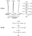
- Figs. 2A and 2B are graphs showing various aberrations of the variable magnification optical system according to the First Example upon focusing on an infinite distance object in the wide-angle end state, and meridional transverse aberration upon correcting image blur for a rotational camera shake of 0.30 degrees, respectively.
- Figs. 3A and 3B are graphs showing various aberrations of the variable magnification optical system according to the First Example upon focusing on the infinite distance object in the telephoto end state, and meridional transverse aberration upon correcting image blur for a rotational camera shake of 0.20 degrees, respectively.
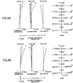
- Figs. 4A and 4B are graphs showing various aberrations of the variable magnification optical system according to the First Example upon focusing on an intermediate distance object in which Fig. 4A shows various aberrations in a wide angle end state, and Fig. 4B shows various aberrations in a telephoto end state.
- Figs. 5A and 5B are graphs showing various aberrations of the variable magnification optical system according to the First Example upon focusing on a close distance object in which Fig. 5A shows various aberrations in a wide angle end state, and Fig. 5B shows various aberrations in a telephoto end state.
- FNO denotes an F-number
- Y denotes an image height
- NA denotes a numerical aperture.
- F-number FNO or the numerical aperture NA with respect to the maximum aperture is shown.
- the maximum value of the image height Y is shown.
- variable magnification optical system according to the First Example shows superb optical performance upon focusing on from an infinite distance object to a close distance object, and further superb optical performance even upon correcting displacement of an imaging position caused by a camera shake or the like.
- Fig. 6 is a sectional view showing a lens configuration of a variable magnification optical system according to the Second Example which is common to the first to the third embodiments of the present application.
- variable magnification optical system is composed of, in order from an object side along the optical axis, a first lens group G1 having positive refractive power, a second lens group G2 having negative refractive power, a third lens group G3 having positive refractive power and a fourth lens group G4 having negative refractive power.
- the first lens group G1 consists of, in order from the object side along the optical axis, a front group G11 having negative refractive power, a focusing lens group GF having positive refractive power and a rear group G12 having positive refractive power.
- the front group G11 consists of, in order from the object side along the optical axis, a fixed lens group G111 having negative refractive power and a vibration reducing lens group GVR having negative refractive power.
- the fixed lens group G111 consists of, in order from the object side along the optical axis, a cemented negative lens constructed by a negative meniscus lens L101 having a convex surface facing the object side cemented with a positive meniscus lens L102 having a convex surface facing the object side.
- the vibration reducing lens group GVR consists of, in order from the object side along the optical axis, a cemented negative lens constructed by a double concave negative lens L103 cemented with a positive meniscus lens L104 having a convex surface facing the object side.
- the focusing lens group GF consists of, in order from the object side along the optical axis, a double convex positive lens L105, a positive meniscus lens L106 having a convex surface facing the object side, and a negative meniscus lens L107 having a convex surface facing the object side.
- the rear group G12 consists of, in order from the object side along the optical axis, a positive meniscus lens L108 having a convex surface facing the object, a negative meniscus lens L109 having a concave surface facing the object side, an aperture stop S and a double convex positive lens L110.
- the second lens group G2 consists of, in order from the object side along the optical axis, a cemented negative lens constructed by a double convex positive lens L201 cemented with a double concave negative lens L202.
- the third lens group G3 consists of, in order from the object side along the optical axis, a cemented positive lens constructed by a negative meniscus lens L301 having a convex surface facing the object side cemented with a double convex positive lens L302.
- the fourth lens group G4 consists of, in order from the object side along the optical axis, a cemented negative lens constructed by a positive meniscus lens L401 having a concave surface facing the object side cemented with a negative meniscus lens L402 having a concave surface facing the object side.
- variable magnification optical system upon varying magnification from the wide-angle end state to the telephoto end state, the second lens group G2 is moved toward the image side along the optical axis, and the third lens group G3 and the fourth lens group G4 are moved toward the object side along the optical axis such that an air interval between the first lens group G1 and the second lens group G2 is increased, an air interval between the second lens group G2 and the third lens group G3 is decreased, and an air interval between the third lens group G3 and the fourth lens group G4 is decreased.
- the first lens group G1 is fixed in a position in the direction of the optical axis.
- variable magnification optical system In the variable magnification optical system according to the present Example, focusing from an infinitely distance object to a close distance object is carried out by moving the focusing lens group GF in the first lens group G1 toward the image side along the optical axis.
- vibration reduction is conducted by moving the vibration reducing lens GVR in the front group G11 to have a component in a direction perpendicular to the optical axis.
- the vibration reducing lens group for correcting the camera shake may be moved by the amount of (f ⁇ tan ⁇ )/K perpendicularly to the optical axis. Accordingly, in the wide-angle end state of the variable magnification optical system according to the present Example, the vibration reduction coefficient K is 0.90, and the focal length is 90.0(mm)(See Table 2 below), so that the moving amount of the vibration reducing lens group GVR for correcting a rotational camera shake of 0.30 degrees is 0.52(mm).
- the vibration reduction coefficient K is 1.34, and the focal length is 133.4(mm) (See Table 2 below), so that the moving amount of the vibration reducing lens group GVR for correcting a rotational camera shake of 0.20 degrees is 0.35(mm).
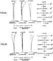
- Figs. 7A and 7B are graphs showing various aberrations of the variable magnification optical system according to the Second Example upon focusing on an infinite distance object in a wide angle end state, and meridional transverse aberration upon correcting image blur for a rotational camera shake of 0.30 degrees, respectively.
- Figs. 8A and 8B are graphs showing various aberrations of the variable magnification optical system according to the Second Example upon focusing on the infinite distance object in the telephoto end state, and meridional transverse aberration upon correcting image blur for a rotational camera shake of 0.20 degrees, respectively.
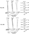
- Figs. 9A and 9B are graphs showing various aberrations of the variable magnification optical system according to the Second Example upon focusing on an intermediate distance object in which Fig. 9A shows various aberrations in a wide angle end state, and Fig. 9B shows various aberrations in a telephoto end state.
- Figs. 10A and 10B are graphs showing various aberrations of the variable magnification optical system according to the Second Example upon focusing on a close distance object in which Fig. 10A shows various aberrations in a wide angle end state, and Fig. 10B shows various aberrations in a telephoto end state.
- variable magnification optical system according to the Second Example shows superb optical performance upon focusing on from an infinite distance object to a close distance object, and further superb optical performance even upon correcting displacement of an imaging position caused by a camera shake or the like.
- variable magnification optical systems in the variable magnification optical systems according to the first to the third embodiments of the present application, a 35mm equivalent focal length is on the order of 60-80 mm, in a wide angle end state and 150-200 mm in a telephoto end state. Further, in the variable magnification optical systems according to the first to the third embodiments of the present application, the variable magnification ratio is on the order of 1.5 to 4. Furthermore, in the variable magnification optical systems according to the first to the third embodiments of the present application, a maximum shooting magnification ß in any focal length state is equal to or exceeds -0.5 and equal to or falls below - 1.0, and a close distance shooting and varying magnification are compatible.
- variable magnification optical systems each having four group configuration were illustrated above as numerical examples of the variable magnification optical systems according to the first to the third embodiments of the present application, the present application is not limited to them and the variable magnification optical systems having other configurations (such as five group configuration, six group configuration, seven group configuration and the like) can be configured.
- a lens configuration that a lens or a lens group is added to the most object side of the variable magnification optical system according to the first to the third embodiments of the present application is possible, and a lens configuration that a lens or a lens group is added to the most image side of the variable magnification optical system according to the first to the third embodiments of the present application is also possible.
- a lens or a lens group may be added between the second lens group G2 and the third lens group G3 to make a configuration having five or more lens groups.
- a lens or a lens group may be added between the third lens group G3 and the fourth lens group G4 to make a configuration having five or more lens groups.
- the third lens group G3 and the fourth lens group G4 may be made to move together upon varying magnification, thereby forming a three group configuration.
- the first lens group G1 is fixed upon varying magnification, but instead thereof the first lens group G1 may be moved in the direction of the optical axis upon varying magnification.
- the first lens group G1 comprises a fixed partial lens group that is fixed upon focusing and upon correcting a camera shake, a focusing lens group that moves in the direction of the optical axis upon focusing and a vibration reducing lens group that moves to have a component in a direction substantially perpendicular to the optical axis upon correcting a camera shake. It is preferable that the first lens group G1 comprises a fixed partial lens group having negative refractive power at the most object side. Although the first lens group G1 comprises two fixed partial lens groups in the each Example as described above, there is not limited to such a configuration. Furthermore, it is preferable that the vibration reduction lens group is arranged at the image side of the focusing lens group.
- variable magnification optical systems according to the first embodiment to the third embodiment of the present application, a portion of a lens group, a single lens group in the entirety thereof, or a plurality of lens groups can be moved in the direction of the optical axis as a focusing lens group. It is particularly preferable that at least a portion of the first lens group is moved as the focusing lens group.
- the focusing lens group can be used for auto focus, and suitable for being driven by a motor for auto focus such as an ultrasonic motor.
- any lens group in the entirety thereof or a portion thereof can be so moved, as a vibration reducing lens group, to have a component in a direction perpendicular to the optical axis, or rotationally moved (swayed) in an in-plane direction including the optical axis for correcting an image blur caused by a camera shake or the like.
- a lens surface of a lens may be a spherical surface, a plane surface, or an aspherical surface.
- a lens surface is a spherical surface or a plane surface, lens processing, assembling and adjustment become easy, and it is possible to prevent deterioration in optical performance caused by errors in lens processing, assembling and adjustment, so that it is preferable.
- deterioration in representation performance is little, so that it is preferable.
- the aspherical surface When a lens surface is an aspherical surface, the aspherical surface may be fabricated by a grinding process, a glass molding process that a glass material is formed into an aspherical shape by a mold, or a compound type process that a resin material on a glass lens surface is formed into an aspherical shape.
- a lens surface may be a diffractive optical surface, and a lens may be a graded-index type lens (GRIN lens) or a plastic lens.
- GRIN lens graded-index type lens
- variable magnification optical systems according to the first embodiment to the third embodiment of the present application, it is preferable that an aperture stop is disposed in the first lens group, and the function may be substituted by a lens frame without disposing a member as an aperture stop.
- the lens surface(s) of the lenses configuring the variable magnification optical systems according to the first embodiment to the third embodiment of the present application may be coated with anti-reflection coating(s) having a high transmittance in a broad wavelength range. With this contrivance, it is feasible to reduce a flare as well as ghost and attain a high optical performance with high contrast.
- Fig. 11 is a view showing a configuration of a lens interchangeable type single lens reflex digital camera equipped with the variable magnification optical system according to the first to the third embodiments of the present application.
- a camera 1 is a lens interchangeable type single lens reflex digital camera equipped with the variable magnification optical system according to the first Example as an imaging lens 2, as shown in Fig. 11 .
- the quick return mirror 3 When the photographer presses an unillustrated release button, the quick return mirror 3 is withdrawn out of the optical path, and the light from the object converged by the imaging lens 2 is imaged on an imaging device 11 and stored in an unillustrated memory as an object image.
- the photographer can take a picture of the object to be imaged by the camera 1.
- the variable magnification optical system according to the First Example mounted on the camera 1 as the imaging lens 2 has a high optical performance upon focusing on from an infinite distance object to a close distance object, and further a high optical performance upon correcting displacement of an imaging position caused by a camera shake or the like. Accordingly, the camera 1 can realize a high optical performance upon focusing on from an infinite distance object to a close distance object, and a high optical performance upon correcting displacement of an imaging position caused by a camera shake or the like. Incidentally, even if the camera is so composed that the variable magnification optical system according to the second Example is mounted on the camera as the imaging lens 2, the same effect can be attained as the camera 1. Moreover, the camera 1 may be a type in which the imaging lens 2 is detachably held, or the imaging lens 2 is integrally formed with the camera 1. The camera 1 can be a type which has no quick return mirror.
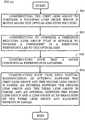
- Fig. 12 is a view showing an outline of a method for manufacturing a variable magnification optical system according to the first embodiment of the present application.
- the method for manufacturing the variable magnification optical system according to the first embodiment of the present application is a method for manufacturing a variable magnification optical system which comprises, in order from an object side, a first lens group having positive refractive power and at least one lens group.
- the method comprises the following steps of S11 and S12.
- Step S11 Constructing the first lens group to comprise a focusing lens group which is moved along the optical axis for focusing and a vibration reducing lens group that is movable to include a component in a direction perpendicular to the optical axis.
- Step S12 Constructing such that, upon varying magnification, an interval between the first lens group and a lens group at an image side of the first lens group and adjacent thereto is varied.
- variable magnification optical system having a high optical performance from upon focusing on an infinite distance object to upon focusing on a close distance object and a high optical performance upon correcting displacement of an imaging position caused by a camera shake or the like.
- variable magnification optical system Next, a method for manufacturing a variable magnification optical system according to the second embodiment of the present application is described.
- Fig. 13 is a view showing an outline of a method for manufacturing a variable magnification optical system according to the second embodiment of the present application.
- the method for manufacturing the variable magnification optical system according to the second embodiment of the present application is a method for manufacturing a variable magnification optical system which comprises, in order from an object side, a first lens group having positive refractive power, a second lens group having negative refractive power, a third lens group having positive refractive power and at least one lens group.
- the method comprises the following steps of S21 and S24.
- Step S21 constructing the first lens group to comprise a focusing lens group which is moved along the optical axis upon focusing.
- Step S22 Constructing to comprise a vibration reducing lens group that is movable to include a component in a direction perpendicular to the optical axis.
- Step S23 Constructing such that the following conditional expression (2-1) is satisfied: 0.2 ⁇ f 1 / ⁇ f 2 ⁇ 2.00 where f1 denotes a focal length of the first lens group, and f2 denotes a focal length of the second lens group.
- Step S24 Constructing such that, upon varying magnification, an interval between the first lens group and the second lens group is varied, an interval between the second lens group and the third lens group is varied, and an interval between the third lens group and a lens group at an image side of the third lens group and adjacent thereto is varied.
- variable magnification optical system having a high optical performance from upon focusing on an infinite distance object to upon focusing on a close distance object and a high optical performance upon correcting displacement of an imaging position caused by a camera shake or the like.
- Fig. 14 is a view showing an outline of a method for manufacturing a variable magnification optical system according to the third embodiment of the present application.
- the method for manufacturing the variable magnification optical system according to the third embodiment of the present application is a method for manufacturing a variable magnification optical system which comprises, in order from an object side along the optical axis, a first lens group having positive refractive power and at least one lens group.
- the method comprises the following steps of S31 to S33.
- variable magnification optical system having a high optical performance from upon focusing on an infinite distance object to upon focusing on a close distance object.
Landscapes
- Physics & Mathematics (AREA)
- General Physics & Mathematics (AREA)
- Optics & Photonics (AREA)
- Nonlinear Science (AREA)
- Lenses (AREA)
- Adjustment Of Camera Lenses (AREA)
Abstract
Description
- The present invention relates to a variable magnification optical system that is suitable to be used for a photographic camera, an electronic still camera, a video camera and the like, an optical device equipped with the variable magnification optical system, and a method for manufacturing the variable magnification optical system.
- There have been proposed a variable magnification optical system suitable for the photographic camera, the electronic still camera, the video camera or the like. See, for example, Japanese Patent application Laid-Open No.
2013-109013 - According to a first aspect of the present application, there is provided a variable magnification optical system comprising, in order from an object side along the optical axis, a first lens group having positive refractive power, and at least one lens group, upon varying magnification, an interval between the first lens group and a lens group at an image side of and adjacent to the first lens group being varied, said first lens group comprising a focusing lens group which is moved along the optical axis for focusing and a vibration reducing lens group that is movable to include a component in a direction perpendicular to the optical axis.
- According to a second aspect of the present application, there is provided a variable magnification optical system comprising, in order from an object side along the optical axis, a first lens group having positive refractive power, a second lens group having negative refractive power, a third lens group having positive refractive power and at least one lens group; upon varying magnification, an interval between the first lens group and the second lens group being varied, an interval between the second lens group and the third lens group being varied and an interval between the third lens group and a lens group at an image side of and adjacent to the third lens group being varied; and_said first lens group comprising a focusing lens group which is moved along the optical axis for focusing; said variable magnification optical system further comprising a vibration reducing lens group that is movable to include a component in a direction perpendicular to the optical axis; and the following conditional expression being satisfied:

- According to a third aspect of the present application, there is provided a variable magnification optical system comprising, in order from an object side along the optical axis, a first lens group having positive refractive power, and at least one lens group; upon varying magnification, an interval between the first lens group and a lens group at an image side of and adjacent to the first lens group being varied; said first lens group comprising, in order from an object side, a front group having negative refractive power and a focusing lens group which is moved along the optical axis for focusing; and the following conditional expression being satisfied:

- According to a fourth aspect of the present application, there is provided an optical apparatus equipped with the variable magnification optical system according to any one of said first to said third aspects of the present application.
- Further, according to a fifth aspect of the present application, there is provided a method for manufacturing a variable magnification optical system comprising, in order from an object side along the optical axis, a first lens group having positive refractive power, and at least one lens group, the method comprising the steps of: constructing said first lens group to comprise a focusing lens group which is moved along the optical axis for focusing and a vibration reducing lens group that is movable to include a component in a direction perpendicular to the optical axis; and constructing such that, upon varying magnification, an interval between the first lens group and a lens group at an image side of and adjacent to the first lens group is varied.
- Further, according to a sixth aspect of the present application, there is provided a method for manufacturing a variable magnification optical system comprising, in order from an object side along the optical axis, a first lens group having positive refractive power, a second lens group having negative refractive power, a third lens group having positive refractive power and at least one lens group,
the method comprising the steps of: - constructing said first lens group to comprise a focusing lens group which is moved along the optical axis for focusing; constructing said variable magnification optical system to comprise further a vibration reducing lens group that is movable to include a component in a direction perpendicular to the optical axis,
- constructing such that the following conditional expression being satisfied:

- constructing such that, upon varying magnification, an interval between the first lens group and the second lens group is varied, an interval between the second lens group and the third lens group is varied and an interval between the third lens group and a lens group at an image side of and adjacent to the third lens group is varied.
- Further, according to a seventh aspect of the present application, there is provided a method for manufacturing a variable magnification optical system comprising, in order from an object side along the optical axis, a first lens group having positive refractive power, and at least one lens group,
the method comprising the steps of: - constructing such that said first lens group comprises, in order from an object side along the optical axis, a front group having negative refractive power and a focusing lens group which is moved along the optical axis for focusing;
- constructing such that the following conditional expression is satisfied:

- where f1 denotes the focal length of the first lens group, and f11 denotes a focal length of said front group; and
- constructing such that, upon varying magnification, an interval between the first lens group and a lens group at an image side of and adjacent to the first lens group is varied.
-
-
Fig. 1 is a sectional view showing a configuration of a variable magnification optical system according to a First Example that is common to a first to a third embodiments of the present application. -
Figs. 2A and 2B are graphs showing various aberrations in the wide-angle end state of the variable magnification optical system according to the First Example of the present application, in whichFig. 2A shows various aberrations in the wide-angle end state upon focusing on an infinite distance object, andFig. 2B shows meridional transverse aberrations when correction of image blur is conducted for rotational camera shake of 0.30 degrees. -
Figs. 3A and 3B are graphs showing various aberrations in the telephoto end state of the variable magnification optical system according to the First Example, in whichFig. 3A shows various aberrations in the telephoto end state upon focusing on an infinite distance object, andFig. 3B shows meridional transverse aberrations when correction of image blur is conducted for rotational camera shake of 0.20 degrees. -
Figs. 4A and 4B are graphs showing various aberrations of the variable magnification optical system according to the First Example upon focusing on an intermediate distance object in the wide angle end state and in the telephoto end state, respectively. -
Figs. 5A and 5B are graphs showing various aberrations of the variable magnification optical system according to the First Example upon focusing on a close distance object in the wide angle end state and in the telephoto end state, respectively. -
Fig. 6 is a sectional view showing a configuration of a variable magnification optical system according to a Second Example that is common to the first to the third embodiments of the present application. -
Figs. 7A and 7B are graphs showing various aberrations in the wide-angle end state of the variable magnification optical system according to the Second Example, in whichFig. 7A shows various aberrations in the wide-angle end state upon focusing on an infinite distance object, andFig. 7B shows meridional transverse aberrations when correction of image blur is conducted for rotational camera shake of 0.30 degrees. -
Figs. 8A and 8B are graphs showing various aberrations in the telephoto end state of the variable magnification optical system according to the Second Example, in whichFig. 8A shows various aberrations in the telephoto end state upon focusing on an infinite distance object, andFig. 8B shows meridional transverse aberrations when correction of image blur is conducted for rotational camera shake of 0.20 degrees. -
Figs. 9A and 9B are graphs showing various aberrations of the variable magnification optical system according to the Second Example upon focusing on an intermediate distance object in the wide angle end state and in the telephoto end state, respectively. -
Figs. 10A and 10B are graphs showing various aberrations of the variable magnification optical system according to the Second Example upon focusing on a close distance object in the wide angle end state and in the telephoto end state, respectively. -
Fig. 11 is a diagram showing a construction of a camera equipped with the variable magnification optical system according to the first to the third embodiments of the present application -
Fig. 12 is a flowchart schematically showing a method for manufacturing the variable magnification optical system according to the first embodiment of the present application. -
Fig. 13 is a flowchart schematically showing a method for manufacturing the variable magnification optical system according to the second embodiment of the present application. -
Fig. 14 is a flowchart schematically showing a method for manufacturing the variable magnification optical system according to the third embodiment of the present application. - Hereinafter, a variable magnification optical system, an optical apparatus and a method for manufacturing the variable magnification optical system, according to the first embodiment of the present application are explained. At first, the variable magnification optical system according to the first embodiment of the present application is explained.
- The variable magnification optical system according to the first embodiment of the present application comprises, in order from an object side along the optical axis: a first lens group having positive refractive power, and at least one lens group; upon varying magnification, an interval between the first lens group and a lens group at an image side of and adjacent to the first lens group being varied; and said first lens group comprising a focusing lens group which is moved along the optical axis for focusing and a vibration reducing lens group that is movable to include a component in a direction perpendicular to the optical axis.
- As described above, in the variable magnification optical system according to the first embodiment of the present application, upon varying magnification, the interval between the first lens group and the lens group at an image side of and adjacent to the first lens group is varied. With this configuration, the variable magnification optical system according to the first embodiment of the present application can correct superbly various aberrations upon varying magnification. In particular, according to the variable magnification optical system according to the first embodiment of the present application, it is possible to secure a predetermined magnification ratio by changing the interval between the first lens group and the lens group at the image side of and adjacent to the first lens group.
- In the variable magnification optical system according to the first embodiment of the present application, said first lens group comprises a focusing lens group which is moved along the optical axis for focusing and a vibration reducing lens group that is movable to include a component in a direction perpendicular to the optical axis, thereby correcting displacement in an imaging position. Thus, various aberrations can be corrected superbly from upon focusing on an infinitely distant object to upon focusing on a close distance object. Moreover, various aberrations can be corrected superbly when correction of displacement in an imaging position caused by a camera shake or the like is conducted.
- In the variable magnification optical system according to the first embodiment of the present application, it is preferable that said first lens group comprises the vibration reducing lens at the image side of the focusing lens. With this configuration, various aberrations can be corrected superbly from upon focusing on an infinitely distant object to upon focusing on a close distance object. Moreover, various aberrations can be corrected superbly when correction of displacement in an imaging position caused by a camera shake or the like is conducted.
- Further, in the variable magnification optical system according to the first embodiment of the present application, it is preferable that the position of said first lens group with respect to the imaging plane is fixed upon varying magnification, thereby it being possible to correct superbly various aberrations upon varying magnification.
- Furthermore, in the variable magnification optical system according to the first embodiment of the present application, it is preferable that the following conditional expression (1-1) is satisfied:

- The conditional expression (1-1) defines the focal length of the first lens group relative to the focal length of the focusing lens group. In the variable magnification optical system according to the first embodiment of the present application, by satisfying the conditional expression (1-1), it is possible to correct superbly various aberrations from upon focusing on an infinitely distant object to upon focusing on a close distance object.
- When the value of f1/fF is equal to or exceeds the upper limit of the conditional expression (1-1), refractive power of the focusing lens group becomes too large, and variation in spherical aberration upon focusing on an infinitely distant object to a close distance object is increased. Meanwhile, in order to ensure the advantageous effect of the present embodiment, it is preferable to set the upper limit value of the conditional expression (1-1) to 3.0.
- On the other hand, when the value of f1/fF is equal to or falls below the lower limit of the conditional expression (1-1), refractive power of the first lens group becomes large, and it becomes difficult to correct spherical aberration and other various aberrations. Further, refractive power of the focusing lens group becomes weak, and amount of movement of the focusing lens group for focusing on an infinite distance object to a close distance object is increased so that the optical system becomes large in size. Meanwhile, in order to ensure the advantageous effect of the present embodiment, it is preferable to set the lower limit value of the conditional expression (1-1) to 0.6.
- Furthermore, in the variable magnification optical system according to the first embodiment of the present application, it is preferable that the focusing lens group has at least two lens components each having positive refractive power. By such a configuration, it is possible to suppress variation in spherical aberration upon focusing on an infinite distance object to a close distance object.
- Furthermore, in the variable magnification optical system according to the first embodiment of the present application, it is preferable that the following conditional expression (1-2) is satisfied:

- The conditional expression (1-2) defines the focal length of the first lens group relative to the focal length of the vibration reducing lens group. In the variable magnification optical system according to the first embodiment of the present application, by satisfying the conditional expression (1-2), it is possible to correct superbly various aberrations upon correcting displacement of an imaging position caused by a camera shake or the like.
- When the value of |f1/fVR| is equal to or exceeds the upper limit of the conditional expression (1-2), refractive power of the vibration reducing lens group becomes large, and generation of eccentric aberration at the time when the vibration reducing lens is moved eccentrically becomes excessive, thereby correction of the eccentric aberration becoming difficult. Meanwhile, in order to ensure the advantageous effect of the present embodiment, it is preferable to set the upper limit value of the conditional expression (1-2) to 1.7.
- On the other hand, when the value of |f1/fVR| is equal to or falls below the lower limit of the conditional expression (1-2), refractive power of the first lens group becomes large, and it becomes difficult to correct spherical aberration and other various aberrations. Further, refractive power of the vibration reducing lens group becomes weak, and amount of eccentric movement of the vibration reducing lens group for correcting the displacement of the imaging position caused by a camera shake or the like, becomes too large so that generation of eccentric aberration becomes excessive, and correction becomes difficult. Meanwhile, in order to ensure the advantageous effect of the present embodiment, it is preferable to set the lower limit value of the conditional expression (1-2) to 0.5.
- Further, it is preferable that the variable magnification optical system according to the first embodiment of the present application comprises, in order from an object side along the optical axis, said first lens group, a second lens group having negative refractive power, a third lens group having positive refractive power, and a fourth lens group having negative refractive power; wherein upon zooming from a wide-angle end state to a telephoto end state, the second lens group is moved toward the image side and the fourth lens group is moved toward the object side. With such a configuration, it is possible to attain desired variable magnification ratio and correct superbly various aberrations upon varying magnification from the wide angle end state to the telephoto end state.
- Further, in the variable magnification optical system according to the first embodiment of the present application, it is preferable that the following conditional expressions (1-3) is satisfied:

- The conditional expression (1-3) defines the focal length of the second lens group relative to the focal length of the third lens group. In the variable magnification optical system according to the first embodiment of the present application, by satisfying the conditional expression (1-3), it is possible to correct superbly various aberrations from the wide angle end state to the telephoto end state.
- When the value of (-f2)/f3 is equal to or exceeds the upper limit of the conditional expression (1-3), refractive power of the third lens group becomes large, and it becomes difficult to correct superbly coma aberration at the wide angle end state. Meanwhile, in order to ensure the advantageous effect of the present embodiment, it is preferable to set the upper limit value of the conditional expression (1-3) to 2.1.
- On the other hand, when the value of (-f2)/f3 is equal to or falls below the lower limit of the conditional expression (1-3), refractive power of the second lens group becomes large, and it becomes difficult to correct spherical aberration at the wide angle end state or at the telephoto end state. Meanwhile, in order to ensure the advantageous effect of the present embodiment, it is preferable to set the lower limit value of the conditional expression (1-3) to 1.4.
- An optical apparatus of the present application comprises the variable magnification optical system having the above described configuration according to the aforementioned first embodiment. By such configuration, it is possible to realize an optical apparatus having a high optical performance from upon focusing on an infinite distance object to upon focusing on a close distance object and a high optical performance upon correcting displacement of an imaging position caused by a camera shake or the like.
- A method for manufacturing a variable magnification optical system according to the first embodiment of the present application is a method for manufacturing a variable magnification optical system which comprises, in order from an object side along the optical axis, a first lens group having positive refractive power, and at least one lens group, the method comprising the steps of: constructing said first lens group to comprise a focusing lens group which is moved along the optical axis for focusing and a vibration reducing lens group that is movable to include a component in a direction perpendicular to the optical axis; and constructing such that, upon varying magnification, an interval between the first lens group and a lens group at an image side of and adjacent to the first lens group is varied. By this method, it is possible to manufacture an optical apparatus having a high optical performance from upon focusing on an infinite distance object to upon focusing on a close distance object and a high optical performance upon correcting displacement of an imaging position caused by a camera shake or the like.
- Hereinafter, a variable magnification optical system, an optical apparatus and a method for manufacturing the variable magnification optical system, according to the second embodiment of the present application are explained. At first, the variable magnification optical system according to the second embodiment of the present application is explained.
- The variable magnification optical system according to the second embodiment of the present application comprises, in order from an object side along the optical axis: a first lens group having positive refractive power, a second lens group having negative refractive power, a third lens group having positive refractive power and at least one lens group; upon varying magnification, an interval between the first lens group and the second lens group being varied, an interval between the second lens group and the third lens group being varied, and an interval between the third lens group and a lens group at an image side of the third lens group and adjacent thereto being varied; said first lens group comprising a focusing lens group which is moved along the optical axis for focusing; said variable magnification optical system further comprising a vibration reducing lens group that is movable to include a component in a direction perpendicular to the optical axis; and the following conditional expression (2-1) being satisfied:

- In the variable magnification optical system according to the second embodiment of the present application, as described above, upon varying magnification, the interval between the first lens group and the second lens group is varied, the interval between the second lens group and the third lens group is varied, and the interval between the third lens group and the lens group at an image side of the third lens group and adjacent thereto is varied. Thus, in the variable magnification optical system according to the second embodiment of the present application, upon varying magnification, the interval between the neighboring lens groups is varied, so various aberrations being able to be excellently corrected. In particular, in the variable magnification optical system according to the second embodiment of the present application, upon varying magnification from a wide angle end state to a telephoto end state, the interval between the first lens group and the second lens group is increased, the interval between the second lens group and the third lens group is decreased, and the interval between the third lens group and the lens group at the image side of the third lens group and adjacent thereto is decreased, whereby a predetermined variable magnification ratio is secured.
- Further, in the variable magnification optical system according to the second embodiment of the present application, the first lens group comprises a focusing lens group that is moved along the optical axis upon focusing, thereby it being possible to correct excellently various aberrations from upon focusing on an infinite distance object to upon focusing a close distance object.
- Further, the variable magnification optical system according to the second embodiment of the present application, comprises a vibration reduction lens group for correcting displacement of an imaging position by moving to include a component in a direction perpendicular to the optical axis. Thus, it is possible to correct various aberrations upon correcting displacement of the imaging position caused by a camera shake and the like.
- The conditional expression (2-1) defines the focal length of the first lens group relative to the focal length of the second lens group. In the variable magnification optical system according to the second embodiment of the present application, by satisfying the conditional expression (2-1), it is possible to correct superbly various aberrations upon varying magnification from a wide angle end state to a telephoto end state.
- When the value of f1/(-f2) is equal to or exceeds the upper limit of the conditional expression (2-1), refractive power of the second lens group becomes too large, and correction of spherical aberration in the wide angle end state or in the telephoto end state becomes difficult. Meanwhile, in order to ensure the advantageous effect of the present embodiment, it is preferable to set the upper limit value of the conditional expression (2-1) to 1.6.
- On the other hand, when the value of f1/(-f2) is equal to or falls below the lower limit of the conditional expression (2-1), refractive power of the first lens group becomes large, and it becomes difficult to correct spherical aberration and other various aberrations. Meanwhile, in order to ensure the advantageous effect of the present embodiment, it is preferable to set the lower limit value of the conditional expression (2-1) to 0.5.
- Furthermore, in the variable magnification optical system according to the second embodiment of the present application, it is preferable that the first lens group has a vibration reducing lens group that is movable to have a component in a direction perpendicular to the optical axis, thereby it being possible to correct excellently various aberrations upon correcting displacement of the imaging position caused by a camera shake or the like.
- Furthermore, in the variable magnification optical system according to the second embodiment of the present application, it is preferable that the first lens group has the vibration reducing lens group at the image side of the focusing lens group, thereby it being possible to correct excellently various aberrations upon focusing on a infinite distance object to focusing on a close distance object. Further, it is possible to correct excellently various aberrations upon correcting displacement of the imaging position caused by a camera shake or the like.
- Furthermore, in the variable magnification optical system according to the second embodiment of the present application, it is preferable that a position of the first lens group is fixed upon varying magnification. By such a configuration, it is possible to correct various aberrations upon varying magnification.
- Further, in the variable magnification optical system according to the second embodiment of the present application, it is preferable that the following conditional expressions (2-2) is satisfied:

- The conditional expression (2-2) defines the focal length of the second lens group relative to the focal length of the third lens group. In the variable magnification optical system according to the second embodiment of the present application, by satisfying the conditional expression (2-2), it is possible to correct superbly various aberrations from the wide angle end state to the telephoto end state.
- When the value of (-f2)/f3 is equal to or exceeds the upper limit of the conditional expression (2-2), refractive power of the third lens group becomes large, and it becomes difficult to correct coma aberration at the wide angle end state. Meanwhile, in order to ensure the advantageous effect of the present embodiment, it is preferable to set the upper limit value of the conditional expression (2-2) to 2.1.
- On the other hand, when the value of (-f2)/f3 is equal to or falls below the lower limit of the conditional expression (2-2), refractive power of the second lens group becomes large, and it becomes difficult to correct spherical aberration in the wide angle end state or in the telephoto end state. Meanwhile, in order to ensure the advantageous effect of the present embodiment, it is preferable to set the lower limit value of the conditional expression (2-2) to 1.4.
- Furthermore, in the variable magnification optical system according to the second embodiment of the present application, it is preferable that the following conditional expression (2-3) is satisfied:

- The conditional expression (2-3) defines the focal length of the first lens group relative to the focal length of the vibration reducing lens group. In the variable magnification optical system according to the second embodiment of the present application, by satisfying the conditional expression (2-3), it is possible to correct superbly various aberrations upon correcting displacement of an imaging position caused by a camera shake or the like.
- When the value of |f1/fVR| is equal to or exceeds the upper limit of the conditional expression (2-3), refractive power of the vibration reducing lens group becomes large, and generation of eccentric aberration at the time when the vibration reducing lens is moved eccentrically becomes excessive, thereby correction of the eccentric aberration becoming difficult. Meanwhile, in order to ensure the advantageous effect of the present embodiment, it is preferable to set the upper limit value of the conditional expression (2-3) to 1.7.
- On the other hand, when the value of |f1/fVR| is equal to or falls below the lower limit of the conditional expression (2-3), refractive power of the first lens group becomes large, and it becomes difficult to correct spherical aberration and other various aberrations. Further, refractive power of the vibration reducing lens group becomes weak, and amount of eccentric movement of the vibration reducing lens group for correcting the displacement of the imaging position caused by a camera shake or the like, becomes too large so that generation of eccentric aberration becomes excessive, and correction becomes difficult. Meanwhile, in order to ensure the advantageous effect of the present embodiment, it is preferable to set the lower limit value of the conditional expression (2-3) to 0.5.
- Further, in the variable magnification optical system according to the second embodiment of the present application, it is preferable that the focusing lens group has at least two lens components each having positive refractive power. With such a configuration, it is possible to suppress variation in spherical aberration upon focusing from an infinite distance object to a close distance object.
- Furthermore, in the variable magnification optical system according to the second embodiment of the present application, it is preferable that the following conditional expression (2-4) is satisfied:

- The conditional expression (2-4) defines the focal length of the first lens group relative to the focal length of the focusing lens group. In the variable magnification optical system according to the second embodiment of the present application, by satisfying the conditional expression (2-4), it is possible to correct superbly various aberrations from upon focusing on an infinitely distant object to upon focusing on a close distance object.
- When the value of f1/fF is equal to or exceeds the upper limit of the conditional expression (2-4), refractive power of the focusing lens group becomes large, and variation in spherical aberration upon focusing on an infinitely distant object to a close distance object is increased. Meanwhile, in order to ensure the advantageous effect of the present embodiment, it is preferable to set the upper limit value of the conditional expression (2-4) to 3.0.
- On the other hand, when the value of f1/fF is equal to or falls below the lower limit of the conditional expression (2-4), refractive power of the first lens group becomes large, and it becomes difficult to correct spherical aberration and other various aberrations. Further, refractive power of the focusing lens group becomes weak, and amount of movement of the focusing lens group for focusing on an infinite distance object to a close distance object is increased so that the optical system becomes large in size. Meanwhile, in order to ensure the advantageous effect of the present embodiment, it is preferable to set the lower limit value of the conditional expression (2-4) to 0.6.
- An optical apparatus of the present application comprises the variable magnification optical system having the above described configuration according to the aforementioned second embodiment. By such configuration, it is possible to realize an optical apparatus having a high optical performance from upon focusing on an infinite distance object to upon focusing on a close distance object and a high optical performance upon correcting displacement of an imaging position caused by a camera shake or the like.
- A method for manufacturing a variable magnification optical system according to the second embodiment of the present application is a method for manufacturing a variable magnification optical system which comprises, in order from an object side along the optical axis, a first lens group having positive refractive power, a second lens group having negative refractive power, a third lens group having positive refractive power, and at least one lens group, the method comprising the steps of: constructing said first lens group to comprise a focusing lens group which is moved along the optical axis for focusing; constructing said variable magnification optical system to comprise further a vibration reducing lens group that is movable to include a component in a direction perpendicular to the optical axis; constructing such that the following conditional expression (2-1) is satisfied:

- Next, a variable magnification optical system, an optical apparatus and a method for manufacturing the variable magnification optical system, according to the third embodiment of the present application are explained. At first, the variable magnification optical system according to the third embodiment of the present application is explained.
- The variable magnification optical system according to the third embodiment of the present application comprises, in order from an object side along the optical axis, a first lens group having positive refractive power and at least one lens group; upon varying magnification, an interval between the first lens group and a lens group at the image side of the first lens group and adjacent thereto being varied; said first lens group comprising, in order from the object side, a front group having negative refractive power and a focusing lens group which is moved along the optical axis for focusing; and the following conditional expression (3-1) being satisfied:

- In the variable magnification optical system according to the third embodiment of the present application, as described above, upon varying magnification, the interval between the first lens group and the lens group at the image side of the first lens group and adjacent thereto is varied. In the variable magnification optical system according to the third embodiment of the present application, with such a configuration, various aberrations can be excellently corrected upon varying magnification. In particular, in the variable magnification optical system according to the third embodiment of the present application, the interval between the first lens group and the lens group at the image side of the first lens group and adjacent thereto is varied, whereby a predetermined variable magnification ratio is secured.
- Further, in the variable magnification optical system according to the third embodiment of the present application, the first lens group comprises, in order from the optical axis, a front group having negative refractive power and a focusing lens group that is moved along the optical axis upon focusing. In the variable magnification optical system according to the third embodiment of the present application, the focusing lens group is arranged in the first lens group as escribed, thereby it being possible to correct excellently various aberrations from upon focusing on an infinite distance object to upon focusing a close distance object.
- The conditional expression (3-1) defines the focal length of the first lens group relative to the focal length of the front group having negative refractive power in the first lens group. By satisfying the conditional expression (3-1), it is possible to correct superbly various aberrations upon from focusing on an infinitely distance object to upon focusing on a close distance object.
- When the value of f1/(-f11) is equal to or exceeds the upper limit of the conditional expression (3-1), refractive power of the front group having negative refractive power becomes large, and generation of spherical aberration and other aberrations become excessive, so correction by the focusing group become necessary. However, if corrections are intended to be made by the focusing group, variation in spherical aberration upon focusing on from an infinitely distance object to a close distance object, is increased. Meanwhile, in order to ensure the advantageous effect of the present embodiment, it is preferable to set the upper limit value of the conditional expression (3-1) to 2.0.
- On the other hand, when the value of f1/(-f11) is equal to or falls below the lower limit of the conditional expression (3-1), refractive power of the first lens group becomes large, and it becomes difficult to correct spherical aberration and other various aberrations. Meanwhile, in order to ensure the advantageous effect of the present embodiment, it is preferable to set the lower limit value of the conditional expression (3-1) to 1.2.
- Furthermore, in the variable magnification optical system according to the third embodiment of the present application, it is preferable that the first lens group has a vibration reducing lens group that is movable to have a component in a direction perpendicular to the optical axis, thereby it being possible to correct excellently various aberrations upon correcting displacement of the imaging position caused by a camera shake or the like.
- Furthermore, in the variable magnification optical system according to the third embodiment of the present application, it is preferable that the first lens group has the vibration reducing lens group at the image side of the focusing lens group, thereby it being possible to correct excellently various aberrations upon focusing on an infinite distance object to focusing on a close distance object. Further, it is possible to correct excellently various aberrations upon correcting displacement of the imaging position caused by a camera shake or the like.
- Furthermore, in the variable magnification optical system according to the third embodiment of the present application, it is preferable that a position of the first lens group is fixed upon varying magnification. By such a configuration, it is possible to correct various aberrations upon varying magnification.
- Furthermore, in the variable magnification optical system according to the third embodiment of the present application, it is preferable that the following conditional expression (3-2) is satisfied:

- The conditional expression (3-2) defines the focal length of the first lens group relative to the focal length of the focusing lens group. In the variable magnification optical system according to the third embodiment of the present application, by satisfying the conditional expression (3-2), it is possible to correct superbly various aberrations from upon focusing on an infinitely distance object to upon focusing on a close distance object.
- When the value of f1/fF is equal to or exceeds the upper limit of the conditional expression (3-2), refractive power of the focusing lens group becomes large, and variation in spherical aberration upon focusing on an infinitely distance object to a close distance object is increased. Meanwhile, in order to ensure the advantageous effect of the present embodiment, it is preferable to set the upper limit value of the conditional expression (3-2) to 3.0.
- On the other hand, when the value of f1/fF is equal to or falls below the lower limit of the conditional expression (3-2), refractive power of the first lens group becomes large, and it becomes difficult to correct spherical aberration and other various aberrations. Further, refractive power of the focusing lens group becomes weak, and amount of movement of the focusing lens group for focusing on an infinite distance object to a close distance object is increased so that the optical system becomes large in size. Meanwhile, in order to ensure the advantageous effect of the present embodiment, it is preferable to set the lower limit value of the conditional expression (3-2) to 0.6.
- Furthermore, in the variable magnification optical system according to the third embodiment of the present application, it is preferable that the focusing lens group has at least two lens components each having positive refractive power. By such a configuration, it is possible to suppress variation in spherical aberration upon focusing on an infinite distance object to a close distance object.
- Furthermore, in the variable magnification optical system according to the third embodiment of the present application, it is preferable that the first lens group comprises further a lens group at an image side of the focusing lens group. By such a configuration, it is possible to correct spherical aberration upon focusing on an infinite distance object to a close distance object.
- Furthermore, it is preferable that the variable magnification optical system according to the third embodiment of the present application comprises, in order from the object side along the optical axis, the first lens group, a second lens group having negative refractive power, a third lens group having positive refractive power and a fourth lens group having negative refractive power; upon varying magnification from a wide angle end state to a telephoto end state, the second lens group being moved toward the image side and the fourth lens group being moved toward the the object side. By such a configuration, it is possible to attain a predetermined variable magnification ratio and correct superbly various aberrations from the wide angle end state to the telephoto end state.
- Further, in the variable magnification optical system according to the third embodiment of the present application, it is preferable that the following conditional expressions (3-3) is satisfied:

- The conditional expression (3-3) defines the focal length of the second lens group relative to the focal length of the third lens group. In the variable magnification optical system according to the third embodiment of the present application, by satisfying the conditional expression (3-3), it is possible to correct superbly various aberrations from the wide angle end state to the telephoto end state.
- When the value of (-f2)/f3 is equal to or exceeds the upper limit of the conditional expression (3-3), refractive power of the third lens group becomes large, and it becomes difficult to correct superbly coma aberration at the wide angle end state. Meanwhile, in order to ensure the advantageous effect of the present embodiment, it is preferable to set the upper limit value of the conditional expression (3-3) to 2.1.
- On the other hand, when the value of (-f2)/f3 is equal to or falls below the lower limit of the conditional expression (3-3), refractive power of the second lens group becomes large, and it becomes difficult to correct spherical aberration at the wide angle end state or at the telephoto end state. Meanwhile, in order to ensure the advantageous effect of the present embodiment, it is preferable to set the lower limit value of the conditional expression (3-3) to 1.4.
- An optical apparatus of the present application comprises the variable magnification optical system having the above described configuration according to the aforementioned third embodiment. By such configuration, it is possible to realize an optical apparatus having a high optical performance from upon focusing on an infinite distance object to upon focusing on a close distance object.
- A method for manufacturing a variable magnification optical system according to the third embodiment of the present application is a method for manufacturing a variable magnification optical system which comprises, in order from an object side along the optical axis, a first lens group having positive refractive power and at least one lens group, the method comprising the steps of: constructing said first lens group to comprise, in order from the object side along the optical axis, a front group having negative refractive power and a focusing lens group which is moved along the optical axis for focusing; constructing such that the following conditional expression (3-1) being satisfied:

- Hereinafter, variable magnification optical systems relating to numerical examples which are common to the first to the third embodiments of the present application will be explained with reference to the accompanying drawings.
-
Fig. 1 is a sectional view showing a lens configuration of a variable magnification optical system according to the First Example which is common to the first to the third embodiments of the present application. Meanwhile, arrows inFig. 1 andFig. 6 described hereinafter shows moving trajectory of each lens upon varying magnification from a wide angle end state (W) to a telephoto end state (T). - The variable magnification optical system according to the present Example is composed of, in order from an object side along the optical axis, a first lens group G1 having positive refractive power, a second lens group G2 having negative refractive power, a third lens group G3 having positive refractive power and a fourth lens group G4 having negative refractive power.
- The first lens group G1 consists of, in order from the object side along the optical axis, a front group G11 having negative refractive power, a focusing lens group GF having positive refractive power and a rear group G12 having positive refractive power.
- The front group G11 consists of, in order from the object side along the optical axis, a cemented negative lens constructed by a plano-concave negative lens L101 having a concave surface facing the image side cemented with a positive meniscus lens L102 having a convex surface facing the object side, and a negative meniscus lens L103 having a concave surface facing the object side.
- The focusing lens group GF consists of, in order from the object side along the optical axis, a double convex positive lens L104, a double convex positive lens L105, a positive meniscus lens L106 having a convex surface facing the object side and a negative meniscus lens L107 having a convex surface facing the object side.
- The rear group G12 consists of, in order from the object side along the optical axis, a fixed lens group G121 having positive refractive power, an aperture stop S and a vibration reducing lens group GVR having positive refractive power.
- The fixed lens group G121 consists of, in order from the object side along the optical axis, a positive meniscus lens L108 having a convex surface facing the object side and a negative meniscus lens L109 having a concave surface facing the object side.
- The vibration reducing lens group GVR consists of, in order from the object side along the optical axis, a cemented positive lens constructed by a double convex positive lens L110 cemented with a negative meniscus lens L111 having a concave surface facing the object side. The positive lens L110 has an aspherical lens surface facing the object side.
- The second lens group G2 consists of, in order from the object side along the optical axis, a double concave negative lens L201 and a positive meniscus lens L202 having a concave surface facing the object side.
- The third lens group G3 consists of, in order from the object side along the optical axis, a cemented positive lens constructed by a negative meniscus lens L301 having a convex surface facing the object side cemented with a double convex positive lens L302.
- The fourth lens group G4 consists of, in order from the object side along the optical axis, a cemented negative lens constructed by a double concave negative lens L401 cemented with a double convex positive lens L402.
- With the above-mentioned configuration, in the variable magnification optical system according to the present Example, upon varying magnification from the wide-angle end state to the telephoto end state, the second lens group G2 is moved toward the image side along the optical axis and the fourth lens group G4 is moved toward the object side along the optical axis such that an air interval between the first lens group G1 and the second lens group G2 is increased, an air interval between the second lens group G2 and the third lens group G3 is decreased, and an air interval between the third lens group G3 and the fourth lens group G4 is decreased.
- At this time, the first lens group G1 and the third lens group G3 are fixed in the respective positions in the direction of the optical axis.
- In the variable magnification optical system according to the present Example, focusing from an infinitely distance object to a close distance object is carried out by moving the focusing lens group GF in the first lens group G1 toward the image side along the optical axis.
- Further, in the variable magnification optical system according to the present Example, vibration reduction is conducted by moving the vibration reducing lens GVR in the rear group G12 to have a component in a direction perpendicular to the optical axis.
- Here, in an entire lens system having a focal length of f, a vibration reduction coefficient(which is a ratio of a moving amount of an image on the image plane I to that of the vibration reducing lens group) of K, in order to correct rotational camera shake of an angle θ, the vibration reducing lens group for correcting the camera shake may be moved by the amount of (f·tanθ)/K perpendicularly to the optical axis. Accordingly, in the wide-angle end state of the variable magnification optical system according to the present Example, the vibration reduction coefficient K is 1.40, and the focal length is 93.4 (mm) (See Table 1 below), so that the moving amount of the vibration reducing lens group GVR for correcting a rotational camera shake of 0.30 degrees is 0.35(mm). In the telephoto end state, the vibration reduction coefficient K is 2.09, and the focal length is 138.9(mm) (See Table 1 below), so that the moving amount of the vibration reducing lens group GVR for correcting a rotational camera shake of 0.20 degrees is 0.23(mm).
- Various values of the variable magnification optical system according to the present Example, are listed in Table 1 below.
- In Table 1, f denotes a focal length, and BF denotes a back focal length, that is, a distance from a most image side lens surface to the image plane I.
- In [Surface Data], "m" shows the lens surface number counted in order from the object side, "r" shows a radius of curvature, "d" shows a face to face distance(that is, a distance from n-th surface(n is an integer) to (n+1)-th surface, "nd" shows refractive index of the material at d-line (wavelength λ=587.6nm), and "νd" shows Abbe number of the material at d-line (wavelength λ=587.6nm). OP denotes an object surface, "Variable" denotes a variable face to face distance, S denotes an aperture stop, and I denotes an image plane. Meanwhile, radius of curvature r=∞ denotes a plane surface, and regarding an aspherical surface, value of a paraxial radius of curvature, is expressed in the column of the radius of curvature with attaching "*" to the surface number. Refractive index of the air nd=1.000000 is omitted.
- In [Aspherical Data], with respect to an aspherical surface shown in [Surface data], an aspherical surface coefficient and a corn constant are shown in the case where the aspherical surface is exhibited by the following expression:

- In [Various Data], FNO denotes an F-number, 2ω denotes an angle of view in degrees, Ymax denotes a maximum image height, TL denotes a total length of the variable magnification optical system of the present Example, that is, a distance on the optical axis from the 1-st surface to the image plane I, and "dn" denotes a face to face distance between the n-th surface (n is an integer) to the (n+1)-th surface. Meanwhile, W denotes a wide-angle end state, T denotes a telephoto end state, INF denotes time upon focusing on an infinite distance object, INT denotes time upon focusing on an intermediate distance object, and CLO denotes time focusing on a close distance object. "ß" denotes a shooting magnification and dO denotes a distance from the object to the 1-st surface.
- In [Lens Group Data], a starting surface number ST and a focal length f of each lens group are shown.
- In [Values for Conditional Expressions], the respective values for the conditional expressions are shown.
- Here, In the Table 1 for "mm" is generally used for the unit of length such as the focal length "f", the radius of curvature "r" and others. However, since similar optical performance can be obtained by an optical system proportionally enlarged or reduced its dimension; the unit is not necessarily to be limited to "mm".
- Meanwhile, symbols used Table 1 described above, are similarly used with respect to the respective examples described later.
(Table 1) First Example [Surface Data] m r d nd νd OP ∞ 1) ∞ 1.000 1.77250 49.62 2) 38.0487 4.926 1.84666 23.78 3) 92.6329 4.033 4) -79.5970 1.000 1.80400 46.60 5) -1847.4278 Variable 6) 439.1344 4.550 1.60300 65.44 7) -79.0578 0.200 8) 70.0266 4.476 1.59319 67.90 9) -1174.3767 0.924 10) 30.2852 5.401 1.51680 63.88 11) 80.2486 7.041 12) 89.7685 1.000 1.80100 34.92 13) 26.2728 Variable 14) 38.2542 3.107 1.71999 50.27 15) 74.6638 2.363 16) -63.7530 1.000 1.78472 25.64 17) -218.9616 1.761 18) (S) ∞ 1.494 *19) 99.6511 4.239 1.74300 49.25 20) -52.5406 1.000 1.80518 25.45 21) -90.0254 Variable 22) -65.1159 1.000 1.80610 40.97 23) 74.9909 1.590 24) -145.6105 8.500 1.84666 23.78 25) -51.3339 Variable 26) 91.8683 1.000 1.84666 23.78 27) 38.8688 8.000 1.73400 51.51 28) -73.0564 Variable 29) -51.7878 1.000 1.80610 40.97 30) 34.9316 6.503 1.84666 23.78 31) -2161.1855 BF I ∞ -
- m:19
- K = 1.0000
- A4 =-1.19910E-06
- A6 = 6.97302E-10
- A8 =-8.64409E-13
- A10= 0.00000E+00
- Variabl magnification Ratio 1.49
W T f 93.38 138.92 FNO 4.64 5.84 2ω 26.52 17.42 Ymax 21.60 21.60 TL 209.56 209.56 BF 38.52 64.02 W T W T W T INF INF INT INT CLO CLO ß 0 0 -0.336 -0.500 -0.672 -1.000 d0 ∞ ∞ 227.867 227.867 88.271 88.271 d5 1.571 1.571 14.171 14.171 25.608 25.608 d13 26.134 26.134 13.534 13.534 2.096 2.096 d21 3.166 35.238 3.166 35.238 3.166 35.238 d25 34.072 2.000 34.072 2.000 34.072 2.000 d28 28.995 3.499 28.995 3.499 28.995 3.499 -
Group ST f 1 1 84.190 2 22 -101.684 3 26 62.362 4 29 -71.534 -
- (1-1) f1/fF = 1.345
- (1-2) |f1/fVR| = 1.267
- (1-3) (-f2)/f3 = 1.631
- (2-1) f1/(-f2) = 0.828
- (2-2) (-f2)/f3 = 1.631
- (2-3) |f1/fVR| = 1.267
- (2-4) f1/fF = 1.345
- (3-1) f1/(-f11) = 1.434
- (3-2) f1/fF = 1.345
- (3-3) (-f2)/f3 = 1.631
-
Figs. 2A and 2B are graphs showing various aberrations of the variable magnification optical system according to the First Example upon focusing on an infinite distance object in the wide-angle end state, and meridional transverse aberration upon correcting image blur for a rotational camera shake of 0.30 degrees, respectively. -
Figs. 3A and 3B are graphs showing various aberrations of the variable magnification optical system according to the First Example upon focusing on the infinite distance object in the telephoto end state, and meridional transverse aberration upon correcting image blur for a rotational camera shake of 0.20 degrees, respectively. -
Figs. 4A and 4B are graphs showing various aberrations of the variable magnification optical system according to the First Example upon focusing on an intermediate distance object in whichFig. 4A shows various aberrations in a wide angle end state, andFig. 4B shows various aberrations in a telephoto end state. -
Figs. 5A and 5B are graphs showing various aberrations of the variable magnification optical system according to the First Example upon focusing on a close distance object in whichFig. 5A shows various aberrations in a wide angle end state, andFig. 5B shows various aberrations in a telephoto end state. - In respective graphs, FNO denotes an F-number, Y denotes an image height, NA denotes a numerical aperture. In graphs showing an aspherical aberration, F-number FNO or the numerical aperture NA with respect to the maximum aperture is shown. In graphs showing astigmatism and distortion, the maximum value of the image height Y is shown. In graphs showing coma aberration, value with respect to each image height is shown. In respective graphs, d denotes aberration curve at d-line (wavelength λ=587.6nm), and g denotes aberration curve at g-line (wavelength λ=435.8nm). In graphs showing astigmatism, a solid line indicates a sagittal image plane, and a broken line indicates a meridional image plane. In graphs showing coma aberrations, coma aberration for each image height is shown. The above-described explanations regarding various aberration graphs are the same as the other Examples.
- As is apparent from the respective graphs, the variable magnification optical system according to the First Example shows superb optical performance upon focusing on from an infinite distance object to a close distance object, and further superb optical performance even upon correcting displacement of an imaging position caused by a camera shake or the like.
-
Fig. 6 is a sectional view showing a lens configuration of a variable magnification optical system according to the Second Example which is common to the first to the third embodiments of the present application. - The variable magnification optical system according to the present Example is composed of, in order from an object side along the optical axis, a first lens group G1 having positive refractive power, a second lens group G2 having negative refractive power, a third lens group G3 having positive refractive power and a fourth lens group G4 having negative refractive power.
- The first lens group G1 consists of, in order from the object side along the optical axis, a front group G11 having negative refractive power, a focusing lens group GF having positive refractive power and a rear group G12 having positive refractive power.
- The front group G11 consists of, in order from the object side along the optical axis, a fixed lens group G111 having negative refractive power and a vibration reducing lens group GVR having negative refractive power.
- The fixed lens group G111 consists of, in order from the object side along the optical axis, a cemented negative lens constructed by a negative meniscus lens L101 having a convex surface facing the object side cemented with a positive meniscus lens L102 having a convex surface facing the object side.
- The vibration reducing lens group GVR consists of, in order from the object side along the optical axis, a cemented negative lens constructed by a double concave negative lens L103 cemented with a positive meniscus lens L104 having a convex surface facing the object side.
- The focusing lens group GF consists of, in order from the object side along the optical axis, a double convex positive lens L105, a positive meniscus lens L106 having a convex surface facing the object side, and a negative meniscus lens L107 having a convex surface facing the object side.
- The rear group G12 consists of, in order from the object side along the optical axis, a positive meniscus lens L108 having a convex surface facing the object, a negative meniscus lens L109 having a concave surface facing the object side, an aperture stop S and a double convex positive lens L110.
- The second lens group G2 consists of, in order from the object side along the optical axis, a cemented negative lens constructed by a double convex positive lens L201 cemented with a double concave negative lens L202.
- The third lens group G3 consists of, in order from the object side along the optical axis, a cemented positive lens constructed by a negative meniscus lens L301 having a convex surface facing the object side cemented with a double convex positive lens L302.
- The fourth lens group G4 consists of, in order from the object side along the optical axis, a cemented negative lens constructed by a positive meniscus lens L401 having a concave surface facing the object side cemented with a negative meniscus lens L402 having a concave surface facing the object side.
- With the above-mentioned configuration, in the variable magnification optical system according to the present Example, upon varying magnification from the wide-angle end state to the telephoto end state, the second lens group G2 is moved toward the image side along the optical axis, and the third lens group G3 and the fourth lens group G4 are moved toward the object side along the optical axis such that an air interval between the first lens group G1 and the second lens group G2 is increased, an air interval between the second lens group G2 and the third lens group G3 is decreased, and an air interval between the third lens group G3 and the fourth lens group G4 is decreased.
- At this time, the first lens group G1 is fixed in a position in the direction of the optical axis.
- In the variable magnification optical system according to the present Example, focusing from an infinitely distance object to a close distance object is carried out by moving the focusing lens group GF in the first lens group G1 toward the image side along the optical axis.
- Further, in the variable magnification optical system according to the present Example, vibration reduction is conducted by moving the vibration reducing lens GVR in the front group G11 to have a component in a direction perpendicular to the optical axis.
- Here, in an entire lens system having a focal length f, a vibration reduction coefficient K, in order to correct rotational camera shake of an angle θ, the vibration reducing lens group for correcting the camera shake may be moved by the amount of (f· tanθ)/K perpendicularly to the optical axis. Accordingly, in the wide-angle end state of the variable magnification optical system according to the present Example, the vibration reduction coefficient K is 0.90, and the focal length is 90.0(mm)(See Table 2 below), so that the moving amount of the vibration reducing lens group GVR for correcting a rotational camera shake of 0.30 degrees is 0.52(mm). In the telephoto end state, the vibration reduction coefficient K is 1.34, and the focal length is 133.4(mm) (See Table 2 below), so that the moving amount of the vibration reducing lens group GVR for correcting a rotational camera shake of 0.20 degrees is 0.35(mm).
- In Table 2 below, various values of the variable magnification optical system according to the present Example, are listed.
(Table 2) Second Example [Surface Data] m r d nd νd OP ∞ 1) 861.6548 1.000 1.74320 49.26 2) 38.3290 4.495 1.85026 32.35 3) 79.8038 5.259 4) -85.9598 1.000 1.80400 46.60 5) 92.0907 3.584 1.84666 23.78 6) 997.0892 Variable 7) 260.1997 4.761 1.61800 63.34 8) -74.4390 0.200 9) 41.1332 4.342 1.60300 65.44 10) 103.6938 10.314 11) 43.4849 1.000 1.80518 25.45 12) 29.2713 Variable 13) 42.0537 3.759 1.64000 60.20 14) 228.3902 2.661 15) -41.3555 1.000 1.67270 32.19 16) -208.5812 5.201 17) (S) ∞ 1.872 18) 498.5465 4.218 1.59319 67.90 19) -47.0125 Variable 20) 66.0924 4.861 1.78472 25.64 21) -37.4130 1.000 1.85026 32.35 22) 38.1753 Variable 23) 75.5943 1.000 1.84666 23.78 24) 32.3808 8.000 1.80400 46.60 25) -87.5713 Variable 26) -40.5857 5.768 1.84666 23.78 27) -22.3442 1.000 1.80400 46.60 28) -327.4524 BF I ∞ -
Variabl magnification Ratio 1.48 W T f 90.00 133.41 FNO 4.57 5.84 2ω 27.32 18.14 Ymax 21.60 21.60 TL 213.84 213.84 BF 38.52 69.27 W T W T W T INF INF INT INT CLO CLO ß 0 0 -0.337 -0.500 -0.675 -1.000 d0 ∞ ∞ 211.657 211.657 77.859 77.859 d6 1.643 1.643 14.823 14.823 27.054 27.054 d12 27.422 27.422 14.243 14.243 2.011 2.011 d19 2.099 31.504 2.099 31.504 2.099 31.504 d22 42.715 3.781 42.715 3.781 42.715 3.781 d25 25.146 3.922 25.146 3. 922 25.146 3.922 -
Group ST f 1 1 84.467 2 20 -88.874 3 23 53.725 4 26 -61.780 -
- (1-1) f1/fF = 1.167
- (1-2) |f1/fVR| = 0.824
- (1-3) (-f2)/f3 = 1.654
- (2-1) f1/(-f2) = 0.950
- (2-2) (-f2)/f3 = 1.654
- (2-3) |f1/fVR| = 0.824
- (2-4) f1/fF = 1.167
- (3-1) f1/(-f11) = 1.430
- (3-2) f1/fF = 1.167
- (3-3) (-f2)/f3 = 1.654
-
Figs. 7A and 7B are graphs showing various aberrations of the variable magnification optical system according to the Second Example upon focusing on an infinite distance object in a wide angle end state, and meridional transverse aberration upon correcting image blur for a rotational camera shake of 0.30 degrees, respectively. -
Figs. 8A and 8B are graphs showing various aberrations of the variable magnification optical system according to the Second Example upon focusing on the infinite distance object in the telephoto end state, and meridional transverse aberration upon correcting image blur for a rotational camera shake of 0.20 degrees, respectively. -
Figs. 9A and 9B are graphs showing various aberrations of the variable magnification optical system according to the Second Example upon focusing on an intermediate distance object in whichFig. 9A shows various aberrations in a wide angle end state, andFig. 9B shows various aberrations in a telephoto end state. -
Figs. 10A and 10B are graphs showing various aberrations of the variable magnification optical system according to the Second Example upon focusing on a close distance object in whichFig. 10A shows various aberrations in a wide angle end state, andFig. 10B shows various aberrations in a telephoto end state. - As is apparent from the respective graphs, the variable magnification optical system according to the Second Example shows superb optical performance upon focusing on from an infinite distance object to a close distance object, and further superb optical performance even upon correcting displacement of an imaging position caused by a camera shake or the like.
- According to the Examples as above-mentioned, it is possible to realize a variable magnification optical system having a superb optical performance from upon focusing on an infinite distance object to upon focusing on a close distance object, and further a superb optical performance upon correcting displacement of an imaging position caused by a camera shake or the like. Note that each of the above described Examples is a concrete example of the invention of the present application, and the invention of the present application is not limited to them. The contents described below can be adopted without deteriorating an optical performance of the variable magnification optical systems of the invention of the present application.
- Meanwhile, in the variable magnification optical systems according to the first to the third embodiments of the present application, a 35mm equivalent focal length is on the order of 60-80 mm, in a wide angle end state and 150-200 mm in a telephoto end state. Further, in the variable magnification optical systems according to the first to the third embodiments of the present application, the variable magnification ratio is on the order of 1.5 to 4. Furthermore, in the variable magnification optical systems according to the first to the third embodiments of the present application, a maximum shooting magnification ß in any focal length state is equal to or exceeds -0.5 and equal to or falls below - 1.0, and a close distance shooting and varying magnification are compatible.
- Although the variable magnification optical systems each having four group configuration were illustrated above as numerical examples of the variable magnification optical systems according to the first to the third embodiments of the present application, the present application is not limited to them and the variable magnification optical systems having other configurations (such as five group configuration, six group configuration, seven group configuration and the like) can be configured. Concretely, a lens configuration that a lens or a lens group is added to the most object side of the variable magnification optical system according to the first to the third embodiments of the present application is possible, and a lens configuration that a lens or a lens group is added to the most image side of the variable magnification optical system according to the first to the third embodiments of the present application is also possible. Alternatively, a lens or a lens group may be added between the second lens group G2 and the third lens group G3 to make a configuration having five or more lens groups. Alternatively, a lens or a lens group may be added between the third lens group G3 and the fourth lens group G4 to make a configuration having five or more lens groups._ Alternatively, the third lens group G3 and the fourth lens group G4 may be made to move together upon varying magnification, thereby forming a three group configuration.
- In each Example described above, the first lens group G1 is fixed upon varying magnification, but instead thereof the first lens group G1 may be moved in the direction of the optical axis upon varying magnification.
- Further, in each Example described above, the first lens group G1 comprises a fixed partial lens group that is fixed upon focusing and upon correcting a camera shake, a focusing lens group that moves in the direction of the optical axis upon focusing and a vibration reducing lens group that moves to have a component in a direction substantially perpendicular to the optical axis upon correcting a camera shake. It is preferable that the first lens group G1 comprises a fixed partial lens group having negative refractive power at the most object side. Although the first lens group G1 comprises two fixed partial lens groups in the each Example as described above, there is not limited to such a configuration. Furthermore, it is preferable that the vibration reduction lens group is arranged at the image side of the focusing lens group.
- Further, in the variable magnification optical systems according to the first embodiment to the third embodiment of the present application, a portion of a lens group, a single lens group in the entirety thereof, or a plurality of lens groups can be moved in the direction of the optical axis as a focusing lens group. It is particularly preferable that at least a portion of the first lens group is moved as the focusing lens group. The focusing lens group can be used for auto focus, and suitable for being driven by a motor for auto focus such as an ultrasonic motor.
- Further, in the variable magnification optical systems according to the first embodiment to the third embodiment of the present application, any lens group in the entirety thereof or a portion thereof can be so moved, as a vibration reducing lens group, to have a component in a direction perpendicular to the optical axis, or rotationally moved (swayed) in an in-plane direction including the optical axis for correcting an image blur caused by a camera shake or the like. Particularly, it is preferable that at least a portion of the first lens group is used as a vibration reducing lens group.
- Further, in the variable magnification optical systems according to the first embodiment to the third embodiment of the present application, a lens surface of a lens may be a spherical surface, a plane surface, or an aspherical surface. When a lens surface is a spherical surface or a plane surface, lens processing, assembling and adjustment become easy, and it is possible to prevent deterioration in optical performance caused by errors in lens processing, assembling and adjustment, so that it is preferable. Moreover, even if an image plane is shifted, deterioration in representation performance is little, so that it is preferable. When a lens surface is an aspherical surface, the aspherical surface may be fabricated by a grinding process, a glass molding process that a glass material is formed into an aspherical shape by a mold, or a compound type process that a resin material on a glass lens surface is formed into an aspherical shape. A lens surface may be a diffractive optical surface, and a lens may be a graded-index type lens (GRIN lens) or a plastic lens.
- Further, in the variable magnification optical systems according to the first embodiment to the third embodiment of the present application, it is preferable that an aperture stop is disposed in the first lens group, and the function may be substituted by a lens frame without disposing a member as an aperture stop.
- Moreover, the lens surface(s) of the lenses configuring the variable magnification optical systems according to the first embodiment to the third embodiment of the present application may be coated with anti-reflection coating(s) having a high transmittance in a broad wavelength range. With this contrivance, it is feasible to reduce a flare as well as ghost and attain a high optical performance with high contrast.
- Next, a camera equipped with the variable magnification optical system according to the first to the third embodiments of the present application, will be explained with referring to
Fig. 11 . -
Fig. 11 is a view showing a configuration of a lens interchangeable type single lens reflex digital camera equipped with the variable magnification optical system according to the first to the third embodiments of the present application. - A
camera 1 is a lens interchangeable type single lens reflex digital camera equipped with the variable magnification optical system according to the first Example as animaging lens 2, as shown inFig. 11 . - In the single lens reflex
digital camera 1 shown inFig.11 , light emitted from an unillustrated object (an object to be imaged) is converged by theimaging lens 2, and forms an image of the object to be imaged on a focusingplate 5 through a quick-return mirror 3. The image of the object to be imaged formed on the focusingplate 5 is reflected a plurality of times in apentagonal prism 7 and led to aneyepiece lens 9. Thus, a photographer can observe the object image througheyepiece lens 9 as an elected image. - When the photographer presses an unillustrated release button, the
quick return mirror 3 is withdrawn out of the optical path, and the light from the object converged by theimaging lens 2 is imaged on an imaging device 11 and stored in an unillustrated memory as an object image. Thus, the photographer can take a picture of the object to be imaged by thecamera 1. - The variable magnification optical system according to the First Example mounted on the
camera 1 as theimaging lens 2 has a high optical performance upon focusing on from an infinite distance object to a close distance object, and further a high optical performance upon correcting displacement of an imaging position caused by a camera shake or the like. Accordingly, thecamera 1 can realize a high optical performance upon focusing on from an infinite distance object to a close distance object, and a high optical performance upon correcting displacement of an imaging position caused by a camera shake or the like. Incidentally, even if the camera is so composed that the variable magnification optical system according to the second Example is mounted on the camera as theimaging lens 2, the same effect can be attained as thecamera 1. Moreover, thecamera 1 may be a type in which theimaging lens 2 is detachably held, or theimaging lens 2 is integrally formed with thecamera 1. Thecamera 1 can be a type which has no quick return mirror. - Next, an outline of a method for manufacturing a variable magnification optical system according to the first embodiment to the third embodiments of the present application is described.
-
Fig. 12 is a view showing an outline of a method for manufacturing a variable magnification optical system according to the first embodiment of the present application. - The method for manufacturing the variable magnification optical system according to the first embodiment of the present application is a method for manufacturing a variable magnification optical system which comprises, in order from an object side, a first lens group having positive refractive power and at least one lens group. The method comprises the following steps of S11 and S12.
- Step S11; Constructing the first lens group to comprise a focusing lens group which is moved along the optical axis for focusing and a vibration reducing lens group that is movable to include a component in a direction perpendicular to the optical axis.
- Step S12; Constructing such that, upon varying magnification, an interval between the first lens group and a lens group at an image side of the first lens group and adjacent thereto is varied.
- According to the method for manufacturing the variable magnification optical system according to the first embodiment of the present application, it is possible to manufacture a variable magnification optical system having a high optical performance from upon focusing on an infinite distance object to upon focusing on a close distance object and a high optical performance upon correcting displacement of an imaging position caused by a camera shake or the like.
- Next, a method for manufacturing a variable magnification optical system according to the second embodiment of the present application is described.
-
Fig. 13 is a view showing an outline of a method for manufacturing a variable magnification optical system according to the second embodiment of the present application. - The method for manufacturing the variable magnification optical system according to the second embodiment of the present application is a method for manufacturing a variable magnification optical system which comprises, in order from an object side, a first lens group having positive refractive power, a second lens group having negative refractive power, a third lens group having positive refractive power and at least one lens group. The method comprises the following steps of S21 and S24.
- Step S21: constructing the first lens group to comprise a focusing lens group which is moved along the optical axis upon focusing.
- Step S22: Constructing to comprise a vibration reducing lens group that is movable to include a component in a direction perpendicular to the optical axis.
- Step S23; Constructing such that the following conditional expression (2-1) is satisfied:

- Step S24: Constructing such that, upon varying magnification, an interval between the first lens group and the second lens group is varied, an interval between the second lens group and the third lens group is varied, and an interval between the third lens group and a lens group at an image side of the third lens group and adjacent thereto is varied.
- According to the method for manufacturing the variable magnification optical system according to the second embodiment of the present application, it is possible to manufacture a variable magnification optical system having a high optical performance from upon focusing on an infinite distance object to upon focusing on a close distance object and a high optical performance upon correcting displacement of an imaging position caused by a camera shake or the like.
- Next, a method for manufacturing a variable magnification optical system according to the third embodiment of the present application is described.
-
Fig. 14 is a view showing an outline of a method for manufacturing a variable magnification optical system according to the third embodiment of the present application. - The method for manufacturing the variable magnification optical system according to the third embodiment of the present application is a method for manufacturing a variable magnification optical system which comprises, in order from an object side along the optical axis, a first lens group having positive refractive power and at least one lens group. The method comprises the following steps of S31 to S33.
- Step S31: Constructing the first lens group to comprise, in order from the object side along the optical axis, a front group having negative refractive power and a focusing lens group which is moved along the optical axis for focusing.
- Step S32: Constructing such that the following conditional expression (3-1) is satisfied:

- Step S33: Constructing such that, upon varying magnification, an interval between the first lens group and a lens group at the image side of the first lens group and adjacent thereto is varied.
- According to the method for manufacturing the variable magnification optical system according to the third embodiment of the present application, it is possible to manufacture a variable magnification optical system having a high optical performance from upon focusing on an infinite distance object to upon focusing on a close distance object.
Claims (17)
- A variable magnification optical system comprising, in order from an object side along the optical axis, a first lens group having positive refractive power, and at least one lens group;
upon varying magnification, an interval between the first lens group and a lens group at an image side of the first lens group and adjacent thereto being varied,
said first lens group comprising a focusing lens group which is moved along the optical axis for focusing and a vibration reducing lens group that is movable to include a component in a direction perpendicular to the optical axis. - A variable magnification optical system comprising, in order from an object side along the optical axis, a first lens group having positive refractive power, a second lens group having negative refractive power, a third lens group having positive refractive power and at least one lens group;
upon varying magnification, an interval between the first lens group and the second lens group being varied, an interval between the second lens group and the third lens group being varied and an interval between the third lens group and a lens group at an image side of the third lens group and adjacent thereto being varied; and
said first lens group comprising a focusing lens group which is moved along the optical axis for focusing;
said variable magnification optical system further comprising a vibration reducing lens group that is movable to include a component in a direction perpendicular to the optical axis; and
the following conditional expression being satisfied:
- A variable magnification optical system comprising, in order from an object side along the optical axis, a first lens group having positive refractive power, and at least one lens group;
upon varying magnification, an interval between the first lens group and a lens group at an image side of the first lens group and adjacent thereto being varied;
said first lens group comprising, in order from the object side along the optical axis, a front group having negative refractive power and a focusing lens group which is moved along the optical axis for focusing; and
the following conditional expression being satisfied:
- A variable magnification optical system according to claim 2 or 3, wherein said first lens group comprises a vibration reducing lens group that is movable to include a component in a direction perpendicular to the optical axis.
- A variable magnification optical system according to claim 1 or 4, wherein said first lens group comprises the vibration reducing lens at the image side of the focusing lenso
- A variable magnification optical system according to any one of claims 1 to 5, wherein the position of said first lens group with respect to the imaging plane is fixed, upon varying magnification.
- A variable magnification optical system according to claim 1 or 2, comprising a vibration reducing lens group that is movable to include a component in a direction perpendicular to the optical axis; and
the following conditional expression being satisfied:
- A variable magnification optical system according to any one of claims 1 to 7, wherein the following conditional expression is satisfied:

- A variable magnification optical system according to any one of claims 1 to 8, wherein the focusing lens group has at least two lens components each having positive refractive power.
- A variable magnification optical system according to any one of claims 1 to 9, wherein the first lens group comprises further a lens group at an image side of the focusing lens group.
- A variable magnification optical system according to any one of claims 1 to 10, comprising, in order from the object side along the optical axis, the first lens group, a second lens group having negative refractive power, a third lens group having positive refractive power and a fourth lens group having negative refractive power.
- A variable magnification optical system according to any one of claims 1 to 11, comprising, in order from the object side along the optical axis, the first lens group, a second lens group, a third lens group and a fourth lens group;
upon varying magnification from a wide angle end state to a telephoto end state, the second lens group being moved toward the image side and the fourth lens group being moved toward the object side. - A variable magnification optical system according to any one of claims 1 to 12, comprising, in order from the object side along the optical axis, the first lens group, a second lens group having negative refractive power, and a third lens group having positive refractive power; and
the following conditional expression being satisfied:
- An optical apparatus comprising a variable magnification optical system according to any one of claim 1 to 13.
- A method for manufacturing a variable magnification optical system comprising, in order from an object side along the optical axis, a first lens group having positive refractive power, and at least one lens group,
the method comprising the steps of:constructing said first lens group to comprise a focusing lens group which is moved along the optical axis for focusing and a vibration reducing lens group that is movable to include a component in a direction perpendicular to the optical axis; andconstructing such that, upon varying magnification, an interval between the first lens group and a lens group at an image side of the first lens group and adjacent thereto is varied. - A method for manufacturing a variable magnification optical system comprising, in order from an object side along the optical axis, a first lens group having positive refractive power, a second lens group having negative refractive power, a third lens group having positive refractive power, and at least one lens group,
the method comprising the steps of:constructing said first lens group to comprise a focusing lens group which is moved along the optical axis for focusing; constructing said variable magnification optical system to comprise further a vibration reducing lens group that is movable to include a component in a direction perpendicular to the optical axis;constructing such that the following conditional expression is satisfied: constructing such that, upon varying magnification, an interval between the first lens group and the second lens group is varied, an interval between the second lens group and the third lens group is varied, and an interval between the third lens group and a lens group at the image side of the third lens group and adjacent thereto is varied.
 - A method for manufacturing a variable magnification optical system comprising, in order from an object side along the optical axis, a first lens group having positive refractive power and at least one lens group,
the method comprising the steps of:constructing said first lens group to comprise, in order from the object side along the optical axis, a front group having negative refractive power and a focusing lens group which is moved along the optical axis for focusing;constructing such that the following conditional expression being satisfied: constructing such that, upon varying magnification, an interval between the first lens group and a lens group at the image side of the first lens group and adjacent thereto is varied.
Applications Claiming Priority (4)
| Application Number | Priority Date | Filing Date | Title |
|---|---|---|---|
| JP2014154838 | 2014-07-30 | ||
| JP2014154839 | 2014-07-30 | ||
| JP2014154837 | 2014-07-30 | ||
| PCT/JP2015/071580 WO2016017724A1 (en) | 2014-07-30 | 2015-07-30 | Variable-power optical system, optical device, and method for manufacturing variable-power optical system |
Publications (3)
| Publication Number | Publication Date |
|---|---|
| EP3176621A1 true EP3176621A1 (en) | 2017-06-07 |
| EP3176621A4 EP3176621A4 (en) | 2018-03-14 |
| EP3176621B1 EP3176621B1 (en) | 2020-08-19 |
Family
ID=55217621
Family Applications (1)
| Application Number | Title | Priority Date | Filing Date |
|---|---|---|---|
| EP15826523.1A Active EP3176621B1 (en) | 2014-07-30 | 2015-07-30 | Variable-power optical system, optical device, and method for manufacturing variable-power optical system |
Country Status (5)
| Country | Link |
|---|---|
| US (1) | US10338357B2 (en) |
| EP (1) | EP3176621B1 (en) |
| JP (3) | JP6610548B2 (en) |
| CN (2) | CN110888226B (en) |
| WO (1) | WO2016017724A1 (en) |
Families Citing this family (6)
| Publication number | Priority date | Publication date | Assignee | Title |
|---|---|---|---|---|
| EP3176621B1 (en) * | 2014-07-30 | 2020-08-19 | Nikon Corporation | Variable-power optical system, optical device, and method for manufacturing variable-power optical system |
| JP7086640B2 (en) * | 2018-02-28 | 2022-06-20 | キヤノン株式会社 | Optical system and an image pickup device having it |
| JP7373371B2 (en) * | 2019-11-27 | 2023-11-02 | 株式会社タムロン | Zoom lens and imaging device |
| WO2022137820A1 (en) * | 2020-12-22 | 2022-06-30 | 株式会社ニコン | Variable-magnification optical system, optical instrument, and method for manufacturing variable-magnification optical system |
| WO2022259650A1 (en) * | 2021-06-09 | 2022-12-15 | 株式会社ニコン | Variable magnification optical system, optical apparatus, and method for manufacturing variable magnification optical system |
| CN116794797A (en) * | 2022-03-14 | 2023-09-22 | 信泰光学(深圳)有限公司 | Optical system |
Family Cites Families (46)
| Publication number | Priority date | Publication date | Assignee | Title |
|---|---|---|---|---|
| JPS594686B2 (en) * | 1975-12-04 | 1984-01-31 | キヤノン株式会社 | Kahenshyouten Kiyori Lens |
| US5040881A (en) * | 1988-05-12 | 1991-08-20 | Canon Kabushiki Kaisha | Image stabilization lens system |
| JPH01284825A (en) * | 1988-05-12 | 1989-11-16 | Canon Inc | Variable magnification optical system with anti-shake function |
| JPH01284824A (en) * | 1988-05-12 | 1989-11-16 | Canon Inc | Variable power optical system with vibration proof function |
| JP2918115B2 (en) * | 1988-09-30 | 1999-07-12 | キヤノン株式会社 | Variable power optical system with vibration proof function |
| JPH02256014A (en) * | 1989-03-29 | 1990-10-16 | Minolta Camera Co Ltd | Compact zoom lens |
| JP3230523B2 (en) * | 1990-11-27 | 2001-11-19 | 株式会社ニコン | Internal focusing zoom lens |
| JPH04362909A (en) * | 1991-01-23 | 1992-12-15 | Nikon Corp | Zoom lens with anti-shake optical system |
| JPH05303035A (en) * | 1992-04-27 | 1993-11-16 | Nikon Corp | Internal focusing super-telephoto zoom lens |
| JP3528947B2 (en) * | 1995-06-08 | 2004-05-24 | 株式会社ニコン | Zoom lens for close-up photography |
| JP2001042214A (en) * | 1999-07-30 | 2001-02-16 | Canon Inc | Zoom lens with anti-vibration function |
| US6493142B1 (en) | 1999-07-30 | 2002-12-10 | Canon Kabushiki Kaisha | Zoom lens and photographing apparatus having it |
| JP4138324B2 (en) * | 2001-11-28 | 2008-08-27 | 松下電器産業株式会社 | Zoom lens and video camera using the same |
| US6853501B2 (en) * | 2002-01-04 | 2005-02-08 | Canon Kabushiki Kaisha | Focusing method selectable zoom optical system |
| JP3599730B2 (en) * | 2002-01-04 | 2004-12-08 | キヤノン株式会社 | Zoom optical system |
| JP2004151619A (en) * | 2002-11-01 | 2004-05-27 | Canon Inc | Zoom lens and optical apparatus having the same |
| JP2005134548A (en) * | 2003-10-29 | 2005-05-26 | Sony Corp | Zoom lens |
| JP4586961B2 (en) * | 2004-03-30 | 2010-11-24 | 株式会社ニコン | Zoom lens with anti-vibration function |
| EP1762876A1 (en) * | 2004-06-29 | 2007-03-14 | Matsushita Electric Industrial Co., Ltd. | Zoom lens system, imaging device, and camera |
| JP4882263B2 (en) * | 2005-03-31 | 2012-02-22 | 株式会社ニコン | Zoom lens |
| JP4817699B2 (en) * | 2005-04-01 | 2011-11-16 | キヤノン株式会社 | Zoom lens and imaging apparatus having the same |
| JP5006076B2 (en) * | 2007-03-26 | 2012-08-22 | 富士フイルム株式会社 | High magnification zoom lens and imaging device |
| CN101276047B (en) * | 2007-03-27 | 2011-05-04 | 亚洲光学股份有限公司 | Zoom lens |
| JP5458477B2 (en) * | 2007-06-29 | 2014-04-02 | 株式会社ニコン | Variable magnification optical system, optical apparatus, and variable magnification optical system magnification method |
| JP5031475B2 (en) * | 2007-07-31 | 2012-09-19 | キヤノン株式会社 | Zoom lens and photographing system having the same |
| JP5267840B2 (en) * | 2007-11-29 | 2013-08-21 | 株式会社ニコン | Zoom lens and optical apparatus provided with the zoom lens |
| JP5115848B2 (en) * | 2008-01-30 | 2013-01-09 | 株式会社ニコン | Variable magnification optical system and optical apparatus equipped with the variable magnification optical system |
| WO2009139253A1 (en) * | 2008-05-11 | 2009-11-19 | 株式会社ニコン | Variable power optical system, optical apparatus equipped with the variable power optical system, and method for manufacturing variable power optical system |
| JP2009294388A (en) * | 2008-06-04 | 2009-12-17 | Tamron Co Ltd | High-magnification wide-angle zoom lens |
| JP5562552B2 (en) * | 2008-12-26 | 2014-07-30 | 株式会社シグマ | Inner focus type anti-vibration lens |
| JP5393259B2 (en) * | 2009-05-27 | 2014-01-22 | キヤノン株式会社 | Zoom lens and imaging apparatus having the same |
| JP5359557B2 (en) * | 2009-05-27 | 2013-12-04 | 株式会社ニコン | Lens system, optical equipment |
| US8503097B2 (en) * | 2009-05-27 | 2013-08-06 | Nikon Corporation | Lens system, optical apparatus and manufacturing method |
| JP5241779B2 (en) * | 2010-07-26 | 2013-07-17 | キヤノン株式会社 | Zoom lens and imaging apparatus having the same |
| JP5582303B2 (en) * | 2010-10-27 | 2014-09-03 | 株式会社ニコン | Variable magnification optical system and optical apparatus having the variable magnification optical system |
| JP5615143B2 (en) * | 2010-11-25 | 2014-10-29 | キヤノン株式会社 | Zoom lens and imaging apparatus having the same |
| JP5907600B2 (en) | 2011-11-17 | 2016-04-26 | キヤノン株式会社 | Zoom lens and imaging apparatus having the same |
| US8867143B2 (en) | 2011-11-16 | 2014-10-21 | Canon Kabushiki Kaisha | Zoom lens and image pickup apparatus including the same |
| JP5663116B2 (en) * | 2012-04-09 | 2015-02-04 | 富士フイルム株式会社 | Zoom lens and imaging device |
| JP5893487B2 (en) * | 2012-04-13 | 2016-03-23 | キヤノン株式会社 | Zoom lens and imaging apparatus having the same |
| JP5911359B2 (en) * | 2012-04-13 | 2016-04-27 | キヤノン株式会社 | Zoom lens and imaging apparatus having the same |
| JP6070055B2 (en) * | 2012-10-23 | 2017-02-01 | 株式会社ニコン | Variable-magnification optical system, optical device, and variable-magnification optical system manufacturing method |
| JP6152641B2 (en) * | 2012-12-26 | 2017-06-28 | リコーイメージング株式会社 | Zoom lens system and electronic imaging apparatus including the same |
| JP6015430B2 (en) * | 2012-12-26 | 2016-10-26 | リコーイメージング株式会社 | Zoom lens system and electronic imaging apparatus including the same |
| JP2016014816A (en) * | 2014-07-03 | 2016-01-28 | キヤノン株式会社 | Zoom lens and imaging device having the same |
| EP3176621B1 (en) * | 2014-07-30 | 2020-08-19 | Nikon Corporation | Variable-power optical system, optical device, and method for manufacturing variable-power optical system |
-
2015
- 2015-07-30 EP EP15826523.1A patent/EP3176621B1/en active Active
- 2015-07-30 WO PCT/JP2015/071580 patent/WO2016017724A1/en not_active Ceased
- 2015-07-30 CN CN201911112292.7A patent/CN110888226B/en active Active
- 2015-07-30 CN CN201580052471.XA patent/CN107076968A/en active Pending
- 2015-07-30 JP JP2016538415A patent/JP6610548B2/en active Active
-
2017
- 2017-01-29 US US15/418,770 patent/US10338357B2/en active Active
-
2019
- 2019-10-29 JP JP2019196418A patent/JP6866914B2/en active Active
-
2021
- 2021-02-18 JP JP2021024247A patent/JP2021092807A/en active Pending
Also Published As
| Publication number | Publication date |
|---|---|
| WO2016017724A1 (en) | 2016-02-04 |
| JP6610548B2 (en) | 2019-11-27 |
| JPWO2016017724A1 (en) | 2017-04-27 |
| JP2021092807A (en) | 2021-06-17 |
| JP6866914B2 (en) | 2021-04-28 |
| US20170176725A1 (en) | 2017-06-22 |
| JP2020034932A (en) | 2020-03-05 |
| CN107076968A (en) | 2017-08-18 |
| US10338357B2 (en) | 2019-07-02 |
| EP3176621B1 (en) | 2020-08-19 |
| CN110888226B (en) | 2022-05-03 |
| EP3176621A4 (en) | 2018-03-14 |
| CN110888226A (en) | 2020-03-17 |
Similar Documents
| Publication | Publication Date | Title |
|---|---|---|
| EP2620796B1 (en) | Optical system and imaging apparatus | |
| EP2360504B1 (en) | Zoom lens system, optical apparatus and method for manufacturing zoom lens system | |
| US9134516B2 (en) | Zoom lens, optical apparatus and method for manufacturing zoom lens | |
| EP3176625B1 (en) | Variable power optical system, optical device, and manufacturing method for variable power optical system | |
| EP2362259B1 (en) | Macro lens of the telephoto type having three lens groups and front focusing, method for its manufacture | |
| US11061210B2 (en) | Variable magnification optical system, optical device, and manufacturing method for variable magnification optical system | |
| EP3176622B1 (en) | Variable-power optical system, optical device, and method for manufacturing variable-power optical system | |
| US20130265653A1 (en) | Imaging lens, optical apparatus equipped therewith and method for manufacturing imaging lens | |
| EP2112542A2 (en) | Optical system, method for focusing, and imaging apparatus equipped therewith | |
| US7889440B2 (en) | Zoom lens, optical apparatus equipped therewith and method for manufacturing the zoom lens | |
| US12352938B2 (en) | Variable magnification optical system, optical device, and method for manufacturing variable magnification optical system | |
| EP3176621B1 (en) | Variable-power optical system, optical device, and method for manufacturing variable-power optical system | |
| EP3351989A1 (en) | Variable magnification optical system, optical device, imaging device, and production method for variable magnification optical system | |
| EP2020613A2 (en) | Optical system | |
| US10690896B2 (en) | Variable magnification optical system, optical device, and production method for variable magnification optical system | |
| EP2921897A1 (en) | Variable power optical assembly, optical device, and variable power optical assembly fabrication method | |
| JP6524703B2 (en) | Zoom lens, optical device, and method of manufacturing zoom lens | |
| EP3136148A1 (en) | Variable power optical system, optical device, and method of manufacturing variable power optical system | |
| EP2916156A1 (en) | Variable magnification optical system, optical device, and production method for variable magnification optical system | |
| US20150185495A1 (en) | Variable-magnification optical system, optical device having same variable-magnification optical system, and method for manufacturing variable-magnification optical system |
Legal Events
| Date | Code | Title | Description |
|---|---|---|---|
| STAA | Information on the status of an ep patent application or granted ep patent |
Free format text: STATUS: THE INTERNATIONAL PUBLICATION HAS BEEN MADE |
|
| 17P | Request for examination filed |
Effective date: 20170227 |
|
| AK | Designated contracting states |
Kind code of ref document: A1 Designated state(s): AL AT BE BG CH CY CZ DE DK EE ES FI FR GB GR HR HU IE IS IT LI LT LU LV MC MK MT NL NO PL PT RO RS SE SI SK SM TR |
|
| AX | Request for extension of the european patent |
Extension state: BA ME |
|
| PUAI | Public reference made under article 153(3) epc to a published international application that has entered the european phase |
Free format text: ORIGINAL CODE: 0009012 |
|
| STAA | Information on the status of an ep patent application or granted ep patent |
Free format text: STATUS: REQUEST FOR EXAMINATION WAS MADE |
|
| DAV | Request for validation of the european patent (deleted) | ||
| DAX | Request for extension of the european patent (deleted) | ||
| A4 | Supplementary search report drawn up and despatched |
Effective date: 20180209 |
|
| RIC1 | Information provided on ipc code assigned before grant |
Ipc: G02B 27/64 20060101ALI20180205BHEP Ipc: G02B 13/18 20060101ALI20180205BHEP Ipc: G02B 15/16 20060101AFI20180205BHEP Ipc: G02B 15/20 20060101ALI20180205BHEP |
|
| STAA | Information on the status of an ep patent application or granted ep patent |
Free format text: STATUS: EXAMINATION IS IN PROGRESS |
|
| 17Q | First examination report despatched |
Effective date: 20190306 |
|
| GRAP | Despatch of communication of intention to grant a patent |
Free format text: ORIGINAL CODE: EPIDOSNIGR1 |
|
| STAA | Information on the status of an ep patent application or granted ep patent |
Free format text: STATUS: GRANT OF PATENT IS INTENDED |
|
| INTG | Intention to grant announced |
Effective date: 20200309 |
|
| GRAS | Grant fee paid |
Free format text: ORIGINAL CODE: EPIDOSNIGR3 |
|
| GRAA | (expected) grant |
Free format text: ORIGINAL CODE: 0009210 |
|
| STAA | Information on the status of an ep patent application or granted ep patent |
Free format text: STATUS: THE PATENT HAS BEEN GRANTED |
|
| RIN1 | Information on inventor provided before grant (corrected) |
Inventor name: MACHIDA, KOSUKE |
|
| AK | Designated contracting states |
Kind code of ref document: B1 Designated state(s): AL AT BE BG CH CY CZ DE DK EE ES FI FR GB GR HR HU IE IS IT LI LT LU LV MC MK MT NL NO PL PT RO RS SE SI SK SM TR |
|
| REG | Reference to a national code |
Ref country code: CH Ref legal event code: EP |
|
| REG | Reference to a national code |
Ref country code: DE Ref legal event code: R096 Ref document number: 602015057826 Country of ref document: DE |
|
| REG | Reference to a national code |
Ref country code: AT Ref legal event code: REF Ref document number: 1304607 Country of ref document: AT Kind code of ref document: T Effective date: 20200915 |
|
| REG | Reference to a national code |
Ref country code: IE Ref legal event code: FG4D |
|
| REG | Reference to a national code |
Ref country code: LT Ref legal event code: MG4D |
|
| REG | Reference to a national code |
Ref country code: NL Ref legal event code: MP Effective date: 20200819 |
|
| PG25 | Lapsed in a contracting state [announced via postgrant information from national office to epo] |
Ref country code: NO Free format text: LAPSE BECAUSE OF FAILURE TO SUBMIT A TRANSLATION OF THE DESCRIPTION OR TO PAY THE FEE WITHIN THE PRESCRIBED TIME-LIMIT Effective date: 20201119 Ref country code: HR Free format text: LAPSE BECAUSE OF FAILURE TO SUBMIT A TRANSLATION OF THE DESCRIPTION OR TO PAY THE FEE WITHIN THE PRESCRIBED TIME-LIMIT Effective date: 20200819 Ref country code: SE Free format text: LAPSE BECAUSE OF FAILURE TO SUBMIT A TRANSLATION OF THE DESCRIPTION OR TO PAY THE FEE WITHIN THE PRESCRIBED TIME-LIMIT Effective date: 20200819 Ref country code: GR Free format text: LAPSE BECAUSE OF FAILURE TO SUBMIT A TRANSLATION OF THE DESCRIPTION OR TO PAY THE FEE WITHIN THE PRESCRIBED TIME-LIMIT Effective date: 20201120 Ref country code: FI Free format text: LAPSE BECAUSE OF FAILURE TO SUBMIT A TRANSLATION OF THE DESCRIPTION OR TO PAY THE FEE WITHIN THE PRESCRIBED TIME-LIMIT Effective date: 20200819 Ref country code: PT Free format text: LAPSE BECAUSE OF FAILURE TO SUBMIT A TRANSLATION OF THE DESCRIPTION OR TO PAY THE FEE WITHIN THE PRESCRIBED TIME-LIMIT Effective date: 20201221 Ref country code: LT Free format text: LAPSE BECAUSE OF FAILURE TO SUBMIT A TRANSLATION OF THE DESCRIPTION OR TO PAY THE FEE WITHIN THE PRESCRIBED TIME-LIMIT Effective date: 20200819 Ref country code: BG Free format text: LAPSE BECAUSE OF FAILURE TO SUBMIT A TRANSLATION OF THE DESCRIPTION OR TO PAY THE FEE WITHIN THE PRESCRIBED TIME-LIMIT Effective date: 20201119 |
|
| REG | Reference to a national code |
Ref country code: AT Ref legal event code: MK05 Ref document number: 1304607 Country of ref document: AT Kind code of ref document: T Effective date: 20200819 |
|
| PG25 | Lapsed in a contracting state [announced via postgrant information from national office to epo] |
Ref country code: NL Free format text: LAPSE BECAUSE OF FAILURE TO SUBMIT A TRANSLATION OF THE DESCRIPTION OR TO PAY THE FEE WITHIN THE PRESCRIBED TIME-LIMIT Effective date: 20200819 Ref country code: PL Free format text: LAPSE BECAUSE OF FAILURE TO SUBMIT A TRANSLATION OF THE DESCRIPTION OR TO PAY THE FEE WITHIN THE PRESCRIBED TIME-LIMIT Effective date: 20200819 Ref country code: RS Free format text: LAPSE BECAUSE OF FAILURE TO SUBMIT A TRANSLATION OF THE DESCRIPTION OR TO PAY THE FEE WITHIN THE PRESCRIBED TIME-LIMIT Effective date: 20200819 Ref country code: LV Free format text: LAPSE BECAUSE OF FAILURE TO SUBMIT A TRANSLATION OF THE DESCRIPTION OR TO PAY THE FEE WITHIN THE PRESCRIBED TIME-LIMIT Effective date: 20200819 Ref country code: IS Free format text: LAPSE BECAUSE OF FAILURE TO SUBMIT A TRANSLATION OF THE DESCRIPTION OR TO PAY THE FEE WITHIN THE PRESCRIBED TIME-LIMIT Effective date: 20201219 |
|
| PG25 | Lapsed in a contracting state [announced via postgrant information from national office to epo] |
Ref country code: SM Free format text: LAPSE BECAUSE OF FAILURE TO SUBMIT A TRANSLATION OF THE DESCRIPTION OR TO PAY THE FEE WITHIN THE PRESCRIBED TIME-LIMIT Effective date: 20200819 Ref country code: RO Free format text: LAPSE BECAUSE OF FAILURE TO SUBMIT A TRANSLATION OF THE DESCRIPTION OR TO PAY THE FEE WITHIN THE PRESCRIBED TIME-LIMIT Effective date: 20200819 Ref country code: EE Free format text: LAPSE BECAUSE OF FAILURE TO SUBMIT A TRANSLATION OF THE DESCRIPTION OR TO PAY THE FEE WITHIN THE PRESCRIBED TIME-LIMIT Effective date: 20200819 Ref country code: CZ Free format text: LAPSE BECAUSE OF FAILURE TO SUBMIT A TRANSLATION OF THE DESCRIPTION OR TO PAY THE FEE WITHIN THE PRESCRIBED TIME-LIMIT Effective date: 20200819 Ref country code: DK Free format text: LAPSE BECAUSE OF FAILURE TO SUBMIT A TRANSLATION OF THE DESCRIPTION OR TO PAY THE FEE WITHIN THE PRESCRIBED TIME-LIMIT Effective date: 20200819 |
|
| REG | Reference to a national code |
Ref country code: DE Ref legal event code: R097 Ref document number: 602015057826 Country of ref document: DE |
|
| PG25 | Lapsed in a contracting state [announced via postgrant information from national office to epo] |
Ref country code: ES Free format text: LAPSE BECAUSE OF FAILURE TO SUBMIT A TRANSLATION OF THE DESCRIPTION OR TO PAY THE FEE WITHIN THE PRESCRIBED TIME-LIMIT Effective date: 20200819 Ref country code: AT Free format text: LAPSE BECAUSE OF FAILURE TO SUBMIT A TRANSLATION OF THE DESCRIPTION OR TO PAY THE FEE WITHIN THE PRESCRIBED TIME-LIMIT Effective date: 20200819 Ref country code: AL Free format text: LAPSE BECAUSE OF FAILURE TO SUBMIT A TRANSLATION OF THE DESCRIPTION OR TO PAY THE FEE WITHIN THE PRESCRIBED TIME-LIMIT Effective date: 20200819 |
|
| PLBE | No opposition filed within time limit |
Free format text: ORIGINAL CODE: 0009261 |
|
| STAA | Information on the status of an ep patent application or granted ep patent |
Free format text: STATUS: NO OPPOSITION FILED WITHIN TIME LIMIT |
|
| PG25 | Lapsed in a contracting state [announced via postgrant information from national office to epo] |
Ref country code: SK Free format text: LAPSE BECAUSE OF FAILURE TO SUBMIT A TRANSLATION OF THE DESCRIPTION OR TO PAY THE FEE WITHIN THE PRESCRIBED TIME-LIMIT Effective date: 20200819 |
|
| 26N | No opposition filed |
Effective date: 20210520 |
|
| PG25 | Lapsed in a contracting state [announced via postgrant information from national office to epo] |
Ref country code: IT Free format text: LAPSE BECAUSE OF FAILURE TO SUBMIT A TRANSLATION OF THE DESCRIPTION OR TO PAY THE FEE WITHIN THE PRESCRIBED TIME-LIMIT Effective date: 20200819 |
|
| PG25 | Lapsed in a contracting state [announced via postgrant information from national office to epo] |
Ref country code: SI Free format text: LAPSE BECAUSE OF FAILURE TO SUBMIT A TRANSLATION OF THE DESCRIPTION OR TO PAY THE FEE WITHIN THE PRESCRIBED TIME-LIMIT Effective date: 20200819 |
|
| REG | Reference to a national code |
Ref country code: CH Ref legal event code: PL |
|
| PG25 | Lapsed in a contracting state [announced via postgrant information from national office to epo] |
Ref country code: MC Free format text: LAPSE BECAUSE OF FAILURE TO SUBMIT A TRANSLATION OF THE DESCRIPTION OR TO PAY THE FEE WITHIN THE PRESCRIBED TIME-LIMIT Effective date: 20200819 |
|
| REG | Reference to a national code |
Ref country code: BE Ref legal event code: MM Effective date: 20210731 |
|
| PG25 | Lapsed in a contracting state [announced via postgrant information from national office to epo] |
Ref country code: LI Free format text: LAPSE BECAUSE OF NON-PAYMENT OF DUE FEES Effective date: 20210731 Ref country code: CH Free format text: LAPSE BECAUSE OF NON-PAYMENT OF DUE FEES Effective date: 20210731 |
|
| PG25 | Lapsed in a contracting state [announced via postgrant information from national office to epo] |
Ref country code: LU Free format text: LAPSE BECAUSE OF NON-PAYMENT OF DUE FEES Effective date: 20210730 |
|
| PG25 | Lapsed in a contracting state [announced via postgrant information from national office to epo] |
Ref country code: IE Free format text: LAPSE BECAUSE OF NON-PAYMENT OF DUE FEES Effective date: 20210730 Ref country code: BE Free format text: LAPSE BECAUSE OF NON-PAYMENT OF DUE FEES Effective date: 20210731 |
|
| PG25 | Lapsed in a contracting state [announced via postgrant information from national office to epo] |
Ref country code: HU Free format text: LAPSE BECAUSE OF FAILURE TO SUBMIT A TRANSLATION OF THE DESCRIPTION OR TO PAY THE FEE WITHIN THE PRESCRIBED TIME-LIMIT; INVALID AB INITIO Effective date: 20150730 |
|
| P01 | Opt-out of the competence of the unified patent court (upc) registered |
Effective date: 20230517 |
|
| PG25 | Lapsed in a contracting state [announced via postgrant information from national office to epo] |
Ref country code: CY Free format text: LAPSE BECAUSE OF FAILURE TO SUBMIT A TRANSLATION OF THE DESCRIPTION OR TO PAY THE FEE WITHIN THE PRESCRIBED TIME-LIMIT Effective date: 20200819 |
|
| PG25 | Lapsed in a contracting state [announced via postgrant information from national office to epo] |
Ref country code: MK Free format text: LAPSE BECAUSE OF FAILURE TO SUBMIT A TRANSLATION OF THE DESCRIPTION OR TO PAY THE FEE WITHIN THE PRESCRIBED TIME-LIMIT Effective date: 20200819 |
|
| PG25 | Lapsed in a contracting state [announced via postgrant information from national office to epo] |
Ref country code: MT Free format text: LAPSE BECAUSE OF FAILURE TO SUBMIT A TRANSLATION OF THE DESCRIPTION OR TO PAY THE FEE WITHIN THE PRESCRIBED TIME-LIMIT Effective date: 20200819 |
|
| PGFP | Annual fee paid to national office [announced via postgrant information from national office to epo] |
Ref country code: GB Payment date: 20250605 Year of fee payment: 11 |
|
| PGFP | Annual fee paid to national office [announced via postgrant information from national office to epo] |
Ref country code: FR Payment date: 20250610 Year of fee payment: 11 |
|
| PGFP | Annual fee paid to national office [announced via postgrant information from national office to epo] |
Ref country code: DE Payment date: 20250604 Year of fee payment: 11 |
|
| PG25 | Lapsed in a contracting state [announced via postgrant information from national office to epo] |
Ref country code: TR Free format text: LAPSE BECAUSE OF FAILURE TO SUBMIT A TRANSLATION OF THE DESCRIPTION OR TO PAY THE FEE WITHIN THE PRESCRIBED TIME-LIMIT Effective date: 20200819 |