EP3176566A1 - Optischer sensor zur messung gelöster gase - Google Patents
Optischer sensor zur messung gelöster gase Download PDFInfo
- Publication number
- EP3176566A1 EP3176566A1 EP15197723.8A EP15197723A EP3176566A1 EP 3176566 A1 EP3176566 A1 EP 3176566A1 EP 15197723 A EP15197723 A EP 15197723A EP 3176566 A1 EP3176566 A1 EP 3176566A1
- Authority
- EP
- European Patent Office
- Prior art keywords
- shaft
- shaft member
- optical sensor
- sensor
- hydrophilic outer
- Prior art date
- Legal status (The legal status is an assumption and is not a legal conclusion. Google has not performed a legal analysis and makes no representation as to the accuracy of the status listed.)
- Withdrawn
Links
- 230000003287 optical effect Effects 0.000 title claims abstract description 61
- 239000007789 gas Substances 0.000 title description 32
- 230000003746 surface roughness Effects 0.000 claims abstract description 17
- 238000004519 manufacturing process Methods 0.000 claims abstract description 9
- 229910001220 stainless steel Inorganic materials 0.000 claims abstract description 7
- 239000010935 stainless steel Substances 0.000 claims abstract description 7
- 238000000034 method Methods 0.000 claims description 16
- 239000002184 metal Substances 0.000 claims description 5
- 238000003486 chemical etching Methods 0.000 claims description 4
- 238000005488 sandblasting Methods 0.000 claims description 4
- 238000000227 grinding Methods 0.000 claims description 3
- 238000005259 measurement Methods 0.000 description 18
- 238000006243 chemical reaction Methods 0.000 description 15
- QVGXLLKOCUKJST-UHFFFAOYSA-N atomic oxygen Chemical compound [O] QVGXLLKOCUKJST-UHFFFAOYSA-N 0.000 description 8
- 239000001301 oxygen Substances 0.000 description 8
- 229910052760 oxygen Inorganic materials 0.000 description 8
- 239000007788 liquid Substances 0.000 description 6
- XLYOFNOQVPJJNP-UHFFFAOYSA-N water Substances O XLYOFNOQVPJJNP-UHFFFAOYSA-N 0.000 description 6
- 239000012491 analyte Substances 0.000 description 5
- 239000007787 solid Substances 0.000 description 5
- 238000004381 surface treatment Methods 0.000 description 5
- 229910052593 corundum Inorganic materials 0.000 description 4
- 239000010431 corundum Substances 0.000 description 4
- VEXZGXHMUGYJMC-UHFFFAOYSA-N Hydrochloric acid Chemical compound Cl VEXZGXHMUGYJMC-UHFFFAOYSA-N 0.000 description 3
- 238000011156 evaluation Methods 0.000 description 3
- 239000000835 fiber Substances 0.000 description 3
- 230000003993 interaction Effects 0.000 description 3
- IJGRMHOSHXDMSA-UHFFFAOYSA-N Atomic nitrogen Chemical compound N#N IJGRMHOSHXDMSA-UHFFFAOYSA-N 0.000 description 2
- CURLTUGMZLYLDI-UHFFFAOYSA-N Carbon dioxide Chemical compound O=C=O CURLTUGMZLYLDI-UHFFFAOYSA-N 0.000 description 2
- 239000011324 bead Substances 0.000 description 2
- 230000001680 brushing effect Effects 0.000 description 2
- 239000003153 chemical reaction reagent Substances 0.000 description 2
- 238000005530 etching Methods 0.000 description 2
- 238000002189 fluorescence spectrum Methods 0.000 description 2
- 230000005661 hydrophobic surface Effects 0.000 description 2
- 239000000463 material Substances 0.000 description 2
- 240000006829 Ficus sundaica Species 0.000 description 1
- GRYLNZFGIOXLOG-UHFFFAOYSA-N Nitric acid Chemical compound O[N+]([O-])=O GRYLNZFGIOXLOG-UHFFFAOYSA-N 0.000 description 1
- 241001306288 Ophrys fuciflora Species 0.000 description 1
- CBENFWSGALASAD-UHFFFAOYSA-N Ozone Chemical compound [O-][O+]=O CBENFWSGALASAD-UHFFFAOYSA-N 0.000 description 1
- 241001494479 Pecora Species 0.000 description 1
- 238000010521 absorption reaction Methods 0.000 description 1
- 238000009825 accumulation Methods 0.000 description 1
- 239000002253 acid Substances 0.000 description 1
- 150000007513 acids Chemical class 0.000 description 1
- 230000032683 aging Effects 0.000 description 1
- QZPSXPBJTPJTSZ-UHFFFAOYSA-N aqua regia Chemical compound Cl.O[N+]([O-])=O QZPSXPBJTPJTSZ-UHFFFAOYSA-N 0.000 description 1
- 239000001569 carbon dioxide Substances 0.000 description 1
- 229910002092 carbon dioxide Inorganic materials 0.000 description 1
- 238000004113 cell culture Methods 0.000 description 1
- 238000001311 chemical methods and process Methods 0.000 description 1
- 238000005516 engineering process Methods 0.000 description 1
- 238000000855 fermentation Methods 0.000 description 1
- 230000004151 fermentation Effects 0.000 description 1
- 239000007792 gaseous phase Substances 0.000 description 1
- 230000005660 hydrophilic surface Effects 0.000 description 1
- 238000007654 immersion Methods 0.000 description 1
- 238000009434 installation Methods 0.000 description 1
- 239000007791 liquid phase Substances 0.000 description 1
- 238000010297 mechanical methods and process Methods 0.000 description 1
- 229910017604 nitric acid Inorganic materials 0.000 description 1
- 229910052757 nitrogen Inorganic materials 0.000 description 1
- 239000013307 optical fiber Substances 0.000 description 1
- 239000012071 phase Substances 0.000 description 1
- 229920000642 polymer Polymers 0.000 description 1
- 238000004886 process control Methods 0.000 description 1
- 239000007790 solid phase Substances 0.000 description 1
- 238000004611 spectroscopical analysis Methods 0.000 description 1
- 238000011282 treatment Methods 0.000 description 1
- 238000009736 wetting Methods 0.000 description 1
Images

Classifications
-
- G—PHYSICS
- G01—MEASURING; TESTING
- G01N—INVESTIGATING OR ANALYSING MATERIALS BY DETERMINING THEIR CHEMICAL OR PHYSICAL PROPERTIES
- G01N21/00—Investigating or analysing materials by the use of optical means, i.e. using sub-millimetre waves, infrared, visible or ultraviolet light
- G01N21/75—Systems in which material is subjected to a chemical reaction, the progress or the result of the reaction being investigated
- G01N21/77—Systems in which material is subjected to a chemical reaction, the progress or the result of the reaction being investigated by observing the effect on a chemical indicator
-
- G—PHYSICS
- G01—MEASURING; TESTING
- G01N—INVESTIGATING OR ANALYSING MATERIALS BY DETERMINING THEIR CHEMICAL OR PHYSICAL PROPERTIES
- G01N21/00—Investigating or analysing materials by the use of optical means, i.e. using sub-millimetre waves, infrared, visible or ultraviolet light
- G01N21/01—Arrangements or apparatus for facilitating the optical investigation
- G01N21/15—Preventing contamination of the components of the optical system or obstruction of the light path
-
- G—PHYSICS
- G01—MEASURING; TESTING
- G01N—INVESTIGATING OR ANALYSING MATERIALS BY DETERMINING THEIR CHEMICAL OR PHYSICAL PROPERTIES
- G01N21/00—Investigating or analysing materials by the use of optical means, i.e. using sub-millimetre waves, infrared, visible or ultraviolet light
- G01N21/62—Systems in which the material investigated is excited whereby it emits light or causes a change in wavelength of the incident light
- G01N21/63—Systems in which the material investigated is excited whereby it emits light or causes a change in wavelength of the incident light optically excited
- G01N21/64—Fluorescence; Phosphorescence
- G01N21/645—Specially adapted constructive features of fluorimeters
-
- G—PHYSICS
- G01—MEASURING; TESTING
- G01N—INVESTIGATING OR ANALYSING MATERIALS BY DETERMINING THEIR CHEMICAL OR PHYSICAL PROPERTIES
- G01N21/00—Investigating or analysing materials by the use of optical means, i.e. using sub-millimetre waves, infrared, visible or ultraviolet light
- G01N21/75—Systems in which material is subjected to a chemical reaction, the progress or the result of the reaction being investigated
-
- G—PHYSICS
- G01—MEASURING; TESTING
- G01N—INVESTIGATING OR ANALYSING MATERIALS BY DETERMINING THEIR CHEMICAL OR PHYSICAL PROPERTIES
- G01N21/00—Investigating or analysing materials by the use of optical means, i.e. using sub-millimetre waves, infrared, visible or ultraviolet light
- G01N21/84—Systems specially adapted for particular applications
- G01N21/85—Investigating moving fluids or granular solids
- G01N21/8507—Probe photometers, i.e. with optical measuring part dipped into fluid sample
-
- G—PHYSICS
- G01—MEASURING; TESTING
- G01N—INVESTIGATING OR ANALYSING MATERIALS BY DETERMINING THEIR CHEMICAL OR PHYSICAL PROPERTIES
- G01N21/00—Investigating or analysing materials by the use of optical means, i.e. using sub-millimetre waves, infrared, visible or ultraviolet light
- G01N21/62—Systems in which the material investigated is excited whereby it emits light or causes a change in wavelength of the incident light
- G01N21/63—Systems in which the material investigated is excited whereby it emits light or causes a change in wavelength of the incident light optically excited
- G01N21/64—Fluorescence; Phosphorescence
- G01N21/6428—Measuring fluorescence of fluorescent products of reactions or of fluorochrome labelled reactive substances, e.g. measuring quenching effects, using measuring "optrodes"
- G01N2021/6434—Optrodes
-
- G—PHYSICS
- G01—MEASURING; TESTING
- G01N—INVESTIGATING OR ANALYSING MATERIALS BY DETERMINING THEIR CHEMICAL OR PHYSICAL PROPERTIES
- G01N21/00—Investigating or analysing materials by the use of optical means, i.e. using sub-millimetre waves, infrared, visible or ultraviolet light
- G01N21/62—Systems in which the material investigated is excited whereby it emits light or causes a change in wavelength of the incident light
- G01N21/63—Systems in which the material investigated is excited whereby it emits light or causes a change in wavelength of the incident light optically excited
- G01N21/64—Fluorescence; Phosphorescence
- G01N21/645—Specially adapted constructive features of fluorimeters
- G01N2021/6484—Optical fibres
-
- G—PHYSICS
- G01—MEASURING; TESTING
- G01N—INVESTIGATING OR ANALYSING MATERIALS BY DETERMINING THEIR CHEMICAL OR PHYSICAL PROPERTIES
- G01N21/00—Investigating or analysing materials by the use of optical means, i.e. using sub-millimetre waves, infrared, visible or ultraviolet light
- G01N21/75—Systems in which material is subjected to a chemical reaction, the progress or the result of the reaction being investigated
- G01N21/77—Systems in which material is subjected to a chemical reaction, the progress or the result of the reaction being investigated by observing the effect on a chemical indicator
- G01N2021/7769—Measurement method of reaction-produced change in sensor
- G01N2021/7786—Fluorescence
Definitions
- the invention relates to the design and manufacture of an optical sensor for measuring at least one gas dissolved in a measuring medium.
- Optical sensors are based on the fact that a chemical reaction between the sensor material and an analyte, here at least one dissolved gas, leads to a change in the optical properties of the sensor in the measurement medium.
- a change in the optical properties can be, for example, a change in the absorption or the fluorescence properties of a sensitive element arranged in the sensor, so that the reaction can subsequently be detected by spectroscopic methods and thus the analyte content, for example as concentration or partial pressure, in the measuring medium can be determined.
- Optical sensors are used, for example, to measure gases dissolved in the measuring medium, such as oxygen, ozone and / or carbon dioxide, in order to determine the gas concentration in the measuring medium, which is given as the partial pressure for dissolved gases.
- gases dissolved in the measuring medium such as oxygen, ozone and / or carbon dioxide
- sparger When used in biological or biotechnical environments and / or processes, it has been found that the introduction of gaseous analytes into the process by means of a gas distributor known as sparger produces gas bubbles which accumulate externally on the sensor and thus also on the sensitive element. In the case of a measurement, this then leads to the fact that the concentration of the analyte in the adhering gas bubbles and not in the measuring medium is measured by an optical sensor.
- the gas bubbles in the measuring medium thus lead to incorrect measurements, measuring tips and / or can even lead to overloading of the optical sensor and / or an alarm message when the optical sensor is designed, for example, to measure low concentration of a dissolved gas in the measuring medium and not on the measurement of the much higher concentrated gas in the accumulated gas bubbles.
- Gaseous analytes such as oxygen in particular, are introduced into a fermentation process with a sparger, for example, in order to grow higher cell cultures and thus to increase the yield.
- Spargers are gas manifolds of different geometries used to introduce gases into process environments or reaction vessels.
- the sparger is often located at the bottom of the reaction vessel, near the agitator, or as a unit with the agitator.
- sensors can be installed at various points in the reaction vessel. Common installation positions of sensors are inter alia from above through the lid or end plate of the reaction vessel or from the side through the wall of the reactor vessel.
- a sensor is often introduced into the same via a flange located on the reaction vessel, wherein the sensor is introduced into the reaction vessel, depending on the configuration, directly or in the interior of a so-called sensor armature.
- the sparger for example, in the case of the fermenter, oxygen bubbles are introduced into the aqueous measuring medium located therein and distributed in the entire fermenter with the aid of the agitator, more precisely the measuring medium therein.
- These gas bubbles can have different sizes and, as already mentioned, deposit on the outside of the optical sensor and / or on the sensitive element and cause measurement peaks, incorrect measurements and / or even overloading.
- the object of the invention is therefore to provide an optical sensor for measuring dissolved gases in a measuring medium, which largely prevents the accumulation of gas bubbles and thus faulty measurement and measuring tips.
- optical sensor for measuring at least one dissolved gas in a measuring medium.
- the optical sensor comprises a sensor head, a shaft element with a recess for a sensitive element and a cylindrical sensor shaft which is arranged between the sensor head and the shaft element.
- the shaft element is characterized in particular by a hydrophilic outer surface.
- An advantage of an inventive optical sensor is that the gas bubbles can not attach to the hydrophilic outer surface and / or bead. In this way, the measuring performance of the optical sensor can be significantly improved, in particular when measuring gases dissolved in an aqueous measuring medium.
- the shaft element further comprises a bevelled end surface in which the recess for the sensitive element is arranged.
- the hydrophilic outer surface of the shaft element in this case comprises at least the bevelled end surface.
- the embodiment with a bevelled end surface is advantageous because the gas bubbles are deflected by the bevel of the end surface and a possible attachment is already prevented due to the geometric conditions.
- the hydrophilic outer surface preferably also comprises at least the parts of the outer surface of the shaft element which, in use, are in contact with the shaft Measuring medium are located, in particular the beveled end surface in which the recess is arranged for the sensitive element, which is in direct contact with the measuring medium during operation. Since the shaft element is preferably interchangeable, it offers production technology to design the entire surface of the shaft element as a hydrophilic outer surface.
- the hydrophilic outer surface of the shaft element has a surface roughness of Ra ⁇ 1 ⁇ m and preferably of Ra ⁇ 0.4 ⁇ m .
- the surface roughness can be determined, for example, with a HOMMEL-ETAMIC T1000 from Jenoptic according to the valid DIN / ISO standards.
- the surface roughness can be expressed as the average roughness R ⁇ in [ ⁇ m] or as a roughness class.
- the hydrophilic outer surface preferably has a surface roughness of at most Ra ⁇ 1 ⁇ m or better than roughness class N7 and in particular of Ra ⁇ 0.4 ⁇ m or better than roughness class N5.
- the surface roughness of the hydrophilic outer surface also influences its contact angle ⁇ .
- the hydrophilic outer surface of the shaft element has a contact angle of ⁇ ⁇ 60 °, preferably between ⁇ ⁇ 40 ° and ⁇ ⁇ 55 ° and in particular between ⁇ ⁇ 45 ° and ⁇ ⁇ 50 °.
- the hydrophilic outer surface of the shaft element has a contact angle ⁇ of ⁇ ⁇ 60 °, preferably between ⁇ ⁇ 10 ° and ⁇ ⁇ 20 ° and in particular between ⁇ ⁇ 12 ° and ⁇ ⁇ 17 °.
- the contact angle ⁇ which can be measured, for example, with a contact angle goniometer, indicates the angle between a solid surface and a liquid on the surface, such as water.
- the contact angle ⁇ depends on the interaction between liquid and solid at the contact boundary and indicates the degree of wetting of the surface with the respective liquid.
- a hydrophobic surface has a high contact angle to water so that water will bead off a hydrophobic surface.
- a hydrophilic surface on the other hand, has a small contact angle, so that the water wets this surface without, for example, defined droplets forming.
- the bevelled end surface of the shaft member may have an angle ⁇ between 25 and 45 degrees, and preferably about 30 degrees.
- An optical sensor with a shaft member having such a beveled end surface is advantageous because gas bubbles can on the one hand not attach to the bevelled end surface and the bevelled end surface on the other hand is not too steep, since it has been shown empirically that a stronger bevel on Due to the increased distance between the sensitive element and an at least partially arranged in the sensor shaft measuring arrangement leads to a significant signal loss.
- the shaft element is preferably made of a metal and in particular of stainless steel.
- the shaft element can be designed as a cylindrical hollow body with a bevelled end surface. Wherein the beveled end surface is disposed at the proximal end of the shaft member and the distal end of the shaft member is configured so that it can be connected to the sensor shaft.
- the shaft member may be fixedly or detachably connected to the sensor shaft, with a releasable connection, such as a screw, clamp or Bayonet connection is preferred.
- distal and proximal are used here in the sense of operation away from the measuring medium (distal) and during operation facing the measuring medium (proximal) used, the distal end of the shaft member is thus in operation or in the operating position of the sensor the measuring medium turned away and facing the proximal end of the measuring medium.
- the optical sensor further comprises a sensitive element, which is arranged in the shaft element and is in contact with the measuring medium during operation of the optical sensor.
- the sensitive element also called sensor spot, comprises, for example, a fluorophore which is sensitive to the at least one dissolved gas to be measured in the measuring medium and is distributed in a carrier.
- the carrier can be configured, for example, as a polymer disk. If a fluorophore is, for example, sensitive to oxygen, its fluorescence spectrum changes upon contact with oxygen, from which the oxygen concentration in the measuring medium can then be determined.
- the optical sensor further comprises a measuring arrangement, the optical and electronic components for measuring the comprises at least one dissolved gas in the measuring medium and is arranged in the sensor head and in the sensor shaft.
- This measuring arrangement comprises, inter alia, a light source, a light guide, a detector and electronic components for controlling and reading these optical components.
- the measuring principle of the optical sensor is based, very simplified, on the fact that light emitted by the light source is passed through the light guide to the sensitive element with shaft element and interacts there with the fluorophore. After interaction with the fluorophore, which is arranged in the sensitive element in contact with the measurement medium, the fluorescence signal is passed through the light guide to the detector.
- the light guide may comprise at least one fiber, a plurality of fibers or a fiber bundle.
- a method for producing an optical sensor according to the invention for measuring at least one dissolved gas in a measuring medium which comprises a sensor head, a shaft element with a recess for a sensitive element and a cylindrical sensor shaft which is arranged between the sensor head and the shaft element can be the following Steps include: manufacturing a shaft member; and creating a hydrophilic outer surface on the shaft member.
- the hydrophilic outer surface of the shaft element can be produced by one of the following methods: sandblasting, chemical etching, brushing and / or grinding.
- the production of the shaft element further comprises the production of a bevelled end surface, in which the recess for the sensitive element is arranged.
- the hydrophilic outer surface is produced at least on the bevelled end surface and preferably on all outer surfaces of the shaft element, which are in contact with the measuring medium during operation.
- the shaft element consists essentially of a metal and in particular of a stainless steel.
- the surface of these materials can be processed by mechanical or chemical processes so that a hydrophilic outer surface results with defined surface parameters.
- the hydrophilic outer surface is produced with a surface roughness of Ra ⁇ 1 ⁇ m and preferably of Ra ⁇ 0.4 ⁇ m .
- the surface roughness Ra can be determined, for example, with a HOMMEL-ETAMIC T1000 from Jenoptic according to the valid DIN / ISO standards.
- the Surface roughness can be expressed as the average roughness Ra in [ ⁇ m] or as roughness class N.
- the hydrophilic outer surface is preferably produced with a surface roughness of at most Ra ⁇ 1 ⁇ m or less than N7 and in particular with Ra ⁇ 0.4 ⁇ m or less than N5.
- the surface roughness of the hydrophilic outer surface also influences the contact angle ⁇ of the hydrophilic outer surface.
- the hydrophilic outer surface of the shaft element with a contact angle of ⁇ ⁇ 60 °, preferably between ⁇ ⁇ 40 ° and ⁇ ⁇ 55 ° and in particular between ⁇ ⁇ 45 ° and ⁇ ⁇ 50 ° generated.
- the hydrophilic outer surface of the shaft element has a contact angle ⁇ of ⁇ ⁇ 60 °, preferably between ⁇ ⁇ 10 ° and ⁇ ⁇ 20 ° and in particular between ⁇ ⁇ 12 ° and ⁇ ⁇ 17 °.
- Other acids such as nitric acid or aqua regia, can be used as an etching reagent.
- a hydrophilic outer surface can be produced on the shaft element, for example by a sandblasting process.
- the shaft element is ground with an outer surface, which was centerless ground without centering, as a further surface treatment with corundum.
- the sheep element at a pressure of 6.0 bar for about 1 min from inside and outside at a beam distance of about 70-80 mm between the nozzle and the outer diameter of the shaft member, or a beam distance of about 15 mm between the nozzle and the bottom of the inner diameter, treated with corundum of the appropriate grain size.
- the resulting surface roughness is determined as already described with a HUMMEL ETAMIC T1000 from Jenoptik.
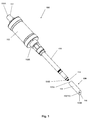
- FIG. 1 1 shows an exploded view of an optical sensor 100 according to the invention.
- the sensor 100 comprises a sensor head 102, a sensor shaft 104 and a shaft element 106.
- the sensor head 102 has a connection 112 in order to connect the sensor 100 to a transmitter, a process control station or another superordinate display device. and / or evaluation unit to connect.
- the sensor head 102 is connected proximally to a cylindrical sensor shaft 104.
- the terms “distal” and “proximal” are here removed in the sense of in operation of the measuring medium (distal) and in use near the measuring medium (proximal).
- the distal end 102A of the sensor head 102 is thus facing away from the measuring medium during operation or in the operating position of the sensor, and the proximal end 102B of the sensor head 102 faces the measuring medium.
- the length of the sensor shaft 104 can be adapted during manufacture depending on the field of application and the desired depth of immersion of the sensor 100. Commercially available optical sensors with total shaft lengths of about 120 mm to about 600 mm.
- the shaft element 106 is attached at the end to the sensor shaft 104, or at the proximal end of the sensor shaft 104. This attachment is detachable, so that the shaft member 106 can be replaced.
- the shaft member 106 may be releasably secured to the sensor shaft 104, for example by snap-fastening, screwing, or a bayonet lock, to name but a few.
- the optical sensor 100 comprises a measuring arrangement (not shown in detail here) with optical and electronic components which are arranged essentially in the sensor head 102 and in the sensor shaft 104.
- optical and electronic components include, but are not limited to, a light source, a light guide 114 which is disposed in the sensor shaft 104 and extends at least to the proximal end 104B of the sensor shaft 104.
- these components include means for converting the optical signals into electronic signals and control components for driving these components.
- the free end of the light guide 114 is in the assembled state of the sensor 100 close behind or even directly on the sensitive element 108, which is in contact with a measuring medium in the operation of the sensor through a recess 110 in the shaft portion 106.
- light from the light source is directed through the light guide 114 to the sensitive element 108 and, after interacting with a fluorophore disposed in the sensitive element, to the detector.
- the fluorophore reacts with an analyte dissolved in the preferably aqueous measuring medium, in particular a dissolved gas, and, after interaction with the introduced light, emits a fluorescence signal which is detected by the detector.
- the analyte concentration in the measuring medium can then be determined.
- the shaft element 106 has a bevelled end surface 116, in which a recess 110 for a sensitive element 108 is formed.
- the beveled end surface 116 shown here preferably has an angle ⁇ of about 30 degrees (s. FIG. 3 ).
- the bevel of the end surface 116 was chosen so that an attachment gas bubbles is already avoided or at least reduced due to the geometry of the sensor element and that the end surface 116 on the other hand as small a slope as possible, so as not to unnecessarily lose optical signal, otherwise due to the combination of the light guide 114 and in the bevelled surface 116 arranged sensitive element 108 may occur.
- the shaft element 106 comprises a hydrophilic outer surface 118, which comprises at least the bevelled end surface 116 with the recess 110 for the sensitive element 108.
- the shaft element 106 is preferably a cylindrical hollow body of a metal and in particular of stainless steel.
- the hydrophilic outer surface 116 of the shaft element 106 is produced by one of the following surface treatments: chemical etching processes, sandblasting, brushing or grinding.
- the surface treatment is controlled such that a hydrophilic outer surface 118 with defined contact angle and / or a defined surface roughness Ra is formed.
- the hydrophilic outer surface 118 has a contact angle ⁇ of less than ⁇ ⁇ 60 °.
- the hydrophilic outer surface 118 with a contact angle between ⁇ ⁇ 40 ° and ⁇ ⁇ 55 ° and in particular between ⁇ ⁇ 45 ° and ⁇ ⁇ 50 ° or between ⁇ ⁇ 10 ° and ⁇ ⁇ 20 °, in particular between ⁇ ⁇ 12 ° and ⁇ ⁇ 17 ° generated.
- the hydrophilic outer surface has a surface roughness of Ra ⁇ 1 ⁇ m or better than N7 and in particular a surface roughness of Ra ⁇ 0.4 ⁇ m or better than N5.
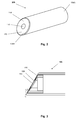
- FIGS. 2 and 3 show a shaft member 106, 206 of an optical sensor according to the invention as a three-dimensional representation and in section.
- the shaft element 106 has a hydrophilic outer surface 118, 218 and a bevelled end surface 116 with a recess 110 for a sensitive element 108.
- This in FIG. 2 Shaft member 206 shown includes a hydrophilic outer surface 218, which includes only the beveled end surface 116.
- the sensitive element 108 is arranged in the shaft element 106, 206 such that it can come into contact with a measuring medium 416 during operation of the sensor (see FIG. FIG. 4 ).
- the shaft element 106, 206 is essentially a cylindrical hollow body which is pushed over the end of the sensor shaft 104 facing away from the sensor head 102 and is detachably fastened thereto.
- the shaft element 106, 206 is exchangeable, since the sensitive element 108 arranged therein, which comprises a fluorophore, undergoes an aging process and can be exchanged if the measuring power is no longer sufficient.
- FIG. 4 schematically shows a reaction vessel 414 with built-in stirrer 402, Sparger 404 and an inventive optical sensor 400.
- a measuring medium 416 is arranged in the reaction vessel 414.
- the sensor 400 is here connected via a cable 405 to a higher-level evaluation and / or display unit 410.
- the sparger 404 is connected via a line 409 with valve to a gas reservoir 412, so that gas bubbles can be introduced into the reaction vessel 414 and distributed evenly with the agitator 402.
- the optical sensor 400 shown here comprises a shaft element 406 with a hydrophilic outer surface and a straight end surface in which a recess for a sensitive element 408 is located at the end.
- FIG. 5 shows a comparison of a measurement curve A of a conventional optical sensor and a measurement curve B of an inventive optical sensor.
- the measured curves were determined with a simplified arrangement according to FIG. 4 added.
- reaction vessel 416 a beaker was filled with water as measuring medium 416, introduced by means of a sparger 404 both oxygen and nitrogen into the beaker and distributed by means of a stirrer 402 in the water.
- a conventional sensor with straight end surface and polished surface was used and the oxygen content was measured in% Air. Noticeable in the first part of the measurement curve A is the multitude of spikes that dominate and distort the measurement result. After approx.
- the conventional optical sensor was exchanged with an optical sensor 100 according to the invention with a hydrophilic outer surface and a bevelled end surface while the measurement was running.
- the second part of the measurement curve B shows a shift of the concentration as a jump in the baseline, since the optical sensor according to the invention was used without calibration, however, the measurement curve B is essentially constant and smooth and is characterized in particular by the absence of the measurement curve A dominating Spikes off.
- an optical sensor 100 according to the invention with a shaft element 106 with a hydrophilic outer surface 118 and a beveled end surface 116 can avoid measuring tips and incorrect measurements and overall a more stable measurement result could be achieved.
Landscapes
- Chemical & Material Sciences (AREA)
- Physics & Mathematics (AREA)
- Health & Medical Sciences (AREA)
- Immunology (AREA)
- Analytical Chemistry (AREA)
- Biochemistry (AREA)
- General Health & Medical Sciences (AREA)
- General Physics & Mathematics (AREA)
- Life Sciences & Earth Sciences (AREA)
- Pathology (AREA)
- Engineering & Computer Science (AREA)
- Chemical Kinetics & Catalysis (AREA)
- Plasma & Fusion (AREA)
- Nuclear Medicine, Radiotherapy & Molecular Imaging (AREA)
- Investigating, Analyzing Materials By Fluorescence Or Luminescence (AREA)
- Optical Measuring Cells (AREA)
Abstract
Optischer Sensor (100, 400) zur Messung mindestens eines gelösten Gases in einem Messmedium und dessen Herstellung, wobei der Sensor einen Sensorkopf (102); ein Schaftelement (106) mit einer Aussparung (110) für ein sensitives Element (108, 408); und einen zylinderförmigen Sensorschaft (104) umfasst, der zwischen dem Sensorkopf (102) und dem Schaftelement (106, 206) angeordnet ist. Das Schaftelement (106, 206) zeichnet sich durch eine hydrophile Aussenfläche (118, 218) aus, die auch durch eine dem Grad der Hydrophilie entsprechende Oberflächenrauigkeit und durch einen Kontaktwinkel gekennzeichnet ist. Das Schaftelement besteht vorzugsweise aus Edelstahl.
Description
- Die Erfindung bezieht sich auf die Ausgestaltung und Herstellung eines optischen Sensors zur Messung mindestens eines in einem Messmedium gelösten Gases.
- Optische Sensoren basieren darauf, dass eine chemische Reaktion zwischen dem Sensormaterial und einem Analyten, hier mindestens ein gelöstes Gas, im Messmedium zu einer Veränderung der optischen Eigenschaften des Sensors führt. Eine Veränderung der optischen Eigenschaften kann beispielsweise in einer Änderung der Absorptions- bzw. der Fluoreszenzeigenschaften eines im Sensor angeordneten sensitiven Elements liegen, sodass die Reaktion in der Folge durch spektroskopische Methoden nachweisbar wird und so der Analytgehalt, zum Beispiel als Konzentration oder Partialdruck, im Messmedium bestimmt werden kann.
- Optische Sensoren werden beispielsweise zur Messung von im Messmedium gelösten Gasen wie Sauerstoff, Ozon und/oder Kohlendioxid eingesetzt, um die Gaskonzentration im Messmedium bestimmen, welche für gelöste Gase als Partialdruck angegeben wird. Bei Einsätzen in biologischen oder biotechnischen Umgebungen und/oder Prozessen hat sich gezeigt, dass durch das Einbringen von gasförmigen Analyten in den Prozess mittels eines als Sparger bekannten Gasverteilers Gasblasen entstehen, welche sich aussen am Sensor und somit auch am sensitiven Element anlagern. Dies führt dann bei einer Messung dazu, dass die Konzentration des Analyten in den anhaftenden Gasblasen und nicht diejenige im Messmedium von einem optischen Sensor gemessen wird. Die Gasblasen im Messmedium führen so zu Fehlmessungen, Messspitzen und/oder können sogar zu einer Überbelastung des optischen Sensors und/oder einer Alarmmeldung führen, wenn der optische Sensor beispielsweise auf die Messung geringer Stoffkonzentration eines im Messmedium gelösten Gases ausgelegt ist und nicht auf die Messung des viel höher konzentrierten Gases in den angelagerten Gasblasen.
- Gasförmige Analyte, wie insbesondere Sauerstoff, werden mit einem Sparger beispielsweise in Fermentationsprozesse eingebracht, um höhere Zellkulturen zu züchten und so die Ausbeute zu erhöhen. Als Sparger werden Gasverteiler unterschiedlicher Geometrien bezeichnet, die zur Einbringung von Gasen in Prozessumgebungen oder Reaktionsbehälter verwendet werden. Der Sparger ist häufig am Boden des Reaktionsbehälters, in der Nähe des Rührwerks oder als Einheit mit dem Rührwerk, angeordnet. Sensoren hingegen können an verschiedenen Stellen des Reaktionsbehälters eingebaut sein. Gängige Einbaupositionen von Sensoren sind unter anderem von oben durch die Deckel- oder Abschlussplatte des Reaktionsbehälters oder von der Seite durch die Wand des Reaktorbehälters hindurch. Ein Sensor wird dabei häufig über einem am Reaktionsbehälter befindlichen Flansch in denselben eingebracht, wobei der Sensor je nach Ausgestaltung direkt oder im Inneren einer sogenannten Sensor-Armatur in den Reaktionsbehälter eingebracht wird. Durch den Sparger werden zum Beispiel in Fall des Fermenters Sauerstoffblasen in das darin befindliche wässrige Messmedium eingebracht und mit Hilfe des Rührwerks im gesamten Fermenter, genauer dem Messmedium darin, verteilt. Diese Gasblasen können unterschiedliche Grössen aufweisen und lagern sich wie bereits erwähnt aussen am optischen Sensor und/oder am sensitiven Element an und verursachen Messspitzen, Fehlmessungen und/oder sogar Überbelastungen.
- Aufgabe der Erfindung ist es daher die Bereitstellung eines optischen Sensors zur Messung gelöster Gase in einem Messmedium, welcher eine Anlagerung von Gasblasen und damit Fehlmessung und Messspitzen weitgehend verhindert.
- Gelöst wird diese Aufgabe durch einen optischen Sensor zur Messung mindestens eines gelösten Gases in einem Messmedium. Der optische Sensor umfasst einen Sensorkopf, ein Schaftelement mit einer Aussparung für ein sensitives Element und einen zylinderförmigen Sensorschaft, der zwischen dem Sensorkopf und dem Schaftelement angeordnet ist. Das Schaftelement zeichnet sich dabei insbesondere durch eine hydrophile Aussenfläche aus.
- Vorteilhaft an einem erfindungsgemässen optischen Sensor ist, dass die Gasblasen sich an der hydrophilen Aussenfläche nicht anlagern können und/oder abperlen. Auf diese Weise kann die Messleistung des optischen Sensors insbesondere bei der Messung von in einem wässrigen Messmedium gelösten Gasen erheblich verbessert werden.
- In einer beispielhaften Ausgestaltung umfasst das Schaftelement zudem eine abgeschrägte Endfläche in welcher die Aussparung für das sensitive Element angeordnet ist. Die hydrophile Aussenfläche des Schaftelements umfasst dabei zumindest die abgeschrägte Endfläche.
- Die Ausgestaltung mit einer abgeschrägten Endfläche ist vorteilhaft, da die Gasblasen durch die Abschrägung von der Endfläche abgelenkt werden und eine mögliche Anlagerung bereits aufgrund der geometrischen Gegebenheiten verhindert wird. Vorzugsweise umfasst die hydrophile Aussenfläche zudem zumindest die Teile der äusseren Oberfläche des Schaftelements, welche sich im Betrieb in Kontakt mit dem Messmedium befinden, insbesondere die abgeschrägte Endfläche, in welcher die Aussparung für das sensitive Element angeordnet ist, welches sich im Betrieb in direktem Kontakt mit dem Messmedium befindet. Da das Schaftelement vorzugsweise austauschbar ist, bietet es sich produktionstechnisch an die komplette Oberfläche des Schaftelements als hydrophile Aussenfläche auszugestalten.
- In einer beispielhaften Ausgestaltung weist die hydrophile Aussenfläche des Schaftelements eine Oberflächenrauigkeit von Ra ≤ 1 µm und vorzugsweise von Ra ≤ 0.4 µm auf. Die Oberflächenrauigkeit kann beispielsweise mit einem HOMMEL-ETAMIC T1000 der Firma Jenoptic gemäss den gültigen DIN/ISO Standards bestimmt werden. Die Oberflächenrauigkeit kann dabei als Mittenrauwert Rα in [µm] oder als Rauheitsklasse ausgedrückt werden. Vorzugsweise weist die hydrophile Aussenfläche eine Oberflächenrauigkeit von maximal Ra ≤ 1 µm bzw. besser als Rauheitsklasse N7 auf und insbesondere von Ra ≤ 0,4 µm bzw. besser als Rauheitsklasse N5 auf.
- Die Oberflächenrauigkeit der hydrophilen Aussenfläche beeinflusst auch deren Kontaktwinkel θ. In einer weiteren Ausgestaltung weist die hydrophile Aussenfläche des Schaftelements einen Kontaktwinkel von θ ≤ 60°, vorzugsweise zwischen θ ≥ 40° und θ ≤ 55° und insbesondere zwischen θ ≥ 45° und θ ≤ 50° auf.
- In einer weiteren Ausgestaltung weist die hydrophile Aussenfläche des Schaftelements einen Kontaktwinkel θ von θ ≤ 60°, vorzugsweise zwischenθ ≥ 10° und θ ≤ 20° und insbesondere zwischen θ ≥ 12° und θ ≤ 17° auf.
- Der Kontaktwinkel θ, welcher beispielsweise mit einem Kontaktwinkel-Goniometer gemessen werden kann, gibt den Winkel zwischen einer festen Oberfläche und einer sich auf der Oberfläche befindlichen Flüssigkeit, wie beispielsweise Wasser an. Der Kontaktwinkel θ hängt dabei von der Wechselwirkung zwischen Flüssigkeit und Feststoff an der Berührungsgrenze ab und gibt den Benetzungsgrad der Oberfläche mit der jeweiligen Flüssigkeit an. Eine hydrophobe Oberfläche weisst einen hohen Kontaktwinkel zu Wasser auf, so dass Wasser von einer hydrophoben Oberfläche abperlt. Eine hydrophile Oberfläche hingegen weisst einen kleinen Kontaktwinkel auf, so das Wasser diese Oberfläche benetzt ohne das sich zum Beispiel definierte Tropfen bilden. Thomas Young definierte 1805 den Kontaktwinkel θ von gasumgebenen Flüssigkeiten auf einer festen Oberfläche als den Winkel an der Phasengrenze der gasförmigen, flüssigen und festen Phasen als γSG = γSL + γLG cosθ mit γSG als Grenzflächenspannung zwischen fest und gasförmig, γSL als Grenzflächenspannung zwischen fest und flüssig, und γLG als Grenzflächenspannung zwischen flüssig und gasförmig.
- Die abgeschrägte Endfläche des Schaftelements kann einen Winkel α zwischen 25 und 45 Grad und vorzugsweise von ca. 30 Grad aufweisen. Ein optischer Sensor mit einem Schaftelement mit einer derartigen abgeschrägten Endfläche ist vorteilhaft, da sich Gasblasen so einerseits gar nicht erst an der abgeschrägten Endfläche anlagern können und die abgeschrägte Endfläche andererseits nicht zu steil ist, da es sich empirisch gezeigt hat, dass eine stärkere Abschrägung auf Grund des vergrösserten Abstands zwischen dem sensitiven Element und einer zumindest teilweise im Sensorschaft angeordneten Messanordnung zu einem deutlichen Signalverlust führt.
- Das Schaftelement besteht vorzugsweise aus einem Metall und insbesondere aus Edelstahl. Das Schaftelement kann dabei als zylinderförmiger Hohlkörper mit einer abgeschrägten Endfläche ausgestaltet sein. Wobei die abgeschrägte Endfläche am proximalen Ende des Schaftelements angeordnet ist und das distale Ende des Schaftelements so ausgestaltet ist, dass es mit dem Sensorschaft verbunden werden kann. Das Schaftelement kann fest oder lösbar mit dem Sensorschaft verbunden werden, wobei eine lösbare Verbindung, wie beispielsweise eine Schraub-, Klemm- oder Bayonet-Verbindung bevorzugt ist.
- Die Begriffe "distal" und "proximal" werden hier im Sinne von im Betrieb vom Messmedium entfernt (distal) und im Betrieb dem Messmediums zugewandt (proximal) verwendet, das distale Ende des Schaftelements ist somit im Betrieb oder in der Betriebslage des Sensors dem Messmedium abgewandt und dessen proximales Ende dem Messmedium zugewandt.
- In einer weiteren Ausgestaltung umfasst der optische Sensor ferner ein sensitives Element, das im Schaftelement angeordnet ist und im Betrieb des optischen Sensors in Kontakt mit dem Messmedium steht. Das sensitive Element, auch Sensor-Spot genannt, umfasst beispielsweise ein Fluorophor, welches auf das mindestens eine zu messende gelöste Gas im Messmedium sensitiv ist und in einem Träger verteilt ist. Der Träger kann beispielweise als Polymerscheibe ausgestaltet sein. Ist ein Fluorophor beispielsweise Sauerstoff sensitiv, so ändert sich bei Kontakt mit Sauerstoff dessen Fluoreszenzspektrum, aus dem dann die Sauerstoffkonzentration im Messmedium bestimmt werden kann.
- In einer beispielhaften Ausgestaltung umfasst der optische Sensor ferner eine Messanordnung, die optische und elektronische Komponenten zur Messung des mindestens einen gelösten Gases im Messmedium umfasst und im Sensorkopf und im Sensorschaft angeordnet ist. Diese Messanordnung umfasst unter anderem eine Lichtquelle, einen Lichtleiter, eine Detektor sowie elektronische Komponenten zur Ansteuerung und Auslesung dieser optischen Komponenten. Das Messprinzip des optischen Sensors basiert, sehr stark vereinfacht dargestellt, darauf, dass von der Lichtquelle ausgesandtes Licht durch den Lichtleiter zum sensitiven Element mit Schaftelement geleitet wird und dort mit dem Fluorphor wechselwirkt. Nach Wechselwirkung mit dem Flurophor, welcher im mit dem Messmedium in Kontakt stehenden sensitiven Element angeordnet ist, wird das Fluoreszenzsignal durch den Lichtleiter zum Detektor geleitet. Der Lichtleiter kann dabei mindestens eine Faser, mehrere Fasern oder ein Faserbündel umfassen.
- Ein Verfahren zur Herstellung eines erfindungsgemässen optischen Sensors zur Messung mindestens eines gelösten Gases in einem Messmedium, welcher einen Sensorkopf, ein Schaftelement mit einer Aussparung für ein sensitives Element und einen zylinderförmigen Sensorschaft, welcher zwischen dem Sensorkopf und dem Schaftelement angeordnet ist umfasst, kann die folgenden Schritte umfassen: Herstellen eines Schaftelements; und Erzeugen einer hydrophilen Aussenfläche auf dem Schaftelement.
- Die hydrophile Aussenfläche des Schaftelements kann durch eines der nachfolgenden Verfahren erzeugt werden: Sandstrahlen, chemisches Ätzen, Bürsten und/oder Schleifen.
- In einer beispielhaften Ausgestaltung umfasst die Herstellung des Schaftelements zudem die Erzeugung einer abgeschrägten Endfläche, in welcher die Aussparung für das sensitive Element angeordnet ist. Die hydrophile Aussenfläche wird zumindest auf der abgeschrägten Endfläche und vorzugsweise auf allen Aussenflächen des Schaftelements erzeugt, welche im Betrieb mit dem Messmedium in Kontakt stehen.
- In einer beispielhaften Ausgestaltung besteht das Schaftelement im Wesentlichen aus einem Metall und insbesondere aus einem Edelstahl. Die Oberfläche dieser Materialien können durch mechanische oder chemische Prozesse so bearbeitet werden, dass eine hydrophile Aussenfläche mit definierten Oberflächenparametern resultiert.
- In einer weiteren Ausgestaltung wird die hydrophile Aussenfläche mit einer Oberflächenrauigkeit von Ra ≤ 1 µm und vorzugweise von Ra ≤ 0,4 µm erzeugt. Die Oberflächenrauigkeit Ra kann beispielsweise mit einem HOMMEL-ETAMIC T1000 der Firma Jenoptic gemäss den gültigen DIN/ISO Standards bestimmt werden. Die Oberflächenrauigkeit kann dabei als Mittenrauwert Ra in [µm] oder als Rauheitsklasse N ausgedrückt werden. Vorzugsweise wird die hydrophile Aussenfläche mit einer Oberflächenrauigkeit von maximal Ra ≤ 1 µm bzw. weniger als N7 und insbesondere mit Ra ≤ 0,4 µm bzw. weniger als N5 erzeugt.
- Die Oberflächenrauigkeit der hydrophilen Aussenfläche beeinflusst auch den Kontaktwinkel θ der hydrophilen Aussenfläche. In einer weiteren Ausgestaltung wird die hydrophile Aussenfläche des Schaftelements mit einem Kontaktwinkel von θ ≤ 60°, vorzugsweise zwischen θ ≥ 40° und θ ≤ 55° und insbesondere zwischen θ ≥ 45° und θ ≤ 50° erzeugt.
- In einer weiteren Ausgestaltung weist die hydrophile Aussenfläche des Schaftelements einen Kontaktwinkel θ von θ ≤ 60°, vorzugsweise zwischenθ ≥ 10° und θ ≤ 20° und insbesondere zwischen θ ≥ 12° und θ ≤ 17° auf.
- Ein chemischer Ätzprozess mit dem die hydrophile Aussenfläche mit definierten Oberflächenparametern erzeugt werden kann, umfasst beispielsweise das Einbringen eines polierten Schaftelements in Salzsäure als Ätz-Reagenz mit einer Konzentration von [HCl] = 1 Mom/L für ca. 24 h. Auch andere Säuren, wie beispielweise Salpetersäure oder Königswasser, können als Ätz-Reagenz eingesetzt werden.
- Mechanisch kann auf dem Schaftelement zum Beispiel durch einen Sandstrahlprozess eine hydrophile Aussenfläche erzeugt werden. Dazu wird das Schaftelement mit einer Aussenfläche, welche spitzenlos rundgeschliffen bzw. centerless-geschliffen wurde, als weitere Oberflächenbehandlung mit Korund geschliffen. Je nach Korngrösse des eingesetzten Korunds können so hydrophile Aussenflächen mit unterschiedlichen Oberflächenparametern erzeugt werden, wie es in der nachfolgenden Tabelle exemplarisch für ein Schaftelement aus Edelstahl dargestellt ist:
Korund Hydrophile Aussenfläche F-Zahl Korngrösse [µm] Rauheit Rauheit in Ra [µm] 180 55 - 90 N6 0.9 220 45 - 75 N6 0.75 280 30 - 40 N6 0.5 320 20 - 30 N6 0.45 400 17.3 N5 0.35 500 10 - 20 N5 0.3 - Dazu wird das Schafelement bei einem Druck von 6,0 bar für ca. 1 min von Innen und Aussen bei einer Strahldistanz von ca. 70-80 mm zwischen der Düse und dem Aussendurchmesser des Schaftelements, bzw. einer Strahldistanz von ca. 15 mm zwischen der Düse und dem Grund des Innendurchmessers, mit Korund der entsprechenden Korngrösse behandelt. Die resultierende Oberflächenrauigkeit wird wie bereits beschrieben mit einem HUMMEL-ETAMIC T1000 der Firma Jenoptik bestimmt.
- Im Folgenden werden anhand der Figuren verschiedene Ausführungsbeispiele eines erfindungsgemässen Schaftelements für einen optischen Sensors näher beschrieben, wobei gleiche Elemente mit gleichen oder ähnlichen Bezugszeichen versehen sind. Die Figuren zeigen:
- Fig. 1
- eine Explosionsdarstellung eines erfindungsgemässen optischen Sensor;
- Fig. 2
- eine dreidimensionale Darstellung eines Schaftelements eines erfindungsgemässen optischen Sensors;
- Fig. 3
- einen Schnitt durch ein Schaftelement eines erfindungsgemässen optischen Sensors;
- Fig. 4
- eine schematische Darstellung eines Reaktionsbehälters mit Rührwerk, Sparger und einem erfindungsgemässen optischen Sensors;
- Fig. 5
- einen Vergleich der Messkurven eines herkömmlichen optischen Sensors und eines erfindungsgemässen optischen Sensors.
-
Figur 1 zeigt eine Explosionsdarstellung eines erfindungsgemässen optischen Sensors 100. Der Sensor 100 umfasst einen Sensorkopf 102, einen Sensorschaft 104 und ein Schaftelement 106. Der Sensorkopf 102 weist einen Anschluss 112 auf, um den Sensor 100 mit einem Transmitter, einer Prozessleitstelle oder einen anderen übergeordneten Anzeige- und/oder Auswerteeinheit zu verbinden. Der Sensorkopf 102 ist proximal mit einem zylinderförmigen Sensorschaft 104 verbunden. Die Begriffe "distal" und "proximal" werden hier im Sinne von im Betrieb vom Messmedium entfernt (distal) und im Betrieb in der Nähe des Messmediums befindlich (proximal) verwendet. Das distale Ende 102A des Sensorkopfes 102 ist somit im Betrieb oder in der Betriebslage des Sensors dem Messmedium abgewandt und das proximale Ende 102B des Sensorkopfes 102 dem Messmedium zugewandt. Die Länge des Sensorschafts 104 kann bei der Herstellung in Abhängigkeit des Einsatzgebiets sowie der gewünschten Eintauchtiefe des Sensors 100 angepasst werden. Kommerziell erhältlich sind optische Sensoren mit Gesamt-Schaftlängen von ca. 120 mm bis ca. 600 mm. Das Schaftelement 106 wird endständig am Sensorschaft 104, bzw. am proximalen Ende des Sensorschafts 104 befestigt. Diese Befestigung ist lösbar, so dass das Schaftelement 106 ausgetauscht werden kann. Das Schaftelement 106 kann zum Beispiel durch Einrasten, Schrauben oder einen Bajonett-Verschluss, um nur einige Möglichkeiten zu nennen, lösbar am Sensorschaft 104 befestigt werden. - Weiterhin umfasst der optische Sensor 100 eine Messanordnung (hier nicht im Detail gezeigt) mit optischen und elektronischen Komponenten, welche im Wesentlichen im Sensorkopf 102 und im Sensorschaft 104 angeordnet sind. Diese Komponenten umfassen unter anderem eine Lichtquelle, einen Lichtleiter 114, welcher im Sensorschaft 104 angeordnet ist und zumindest bis zum proximalen Ende 104B des Sensorschafts 104 reicht. Zudem umfassen diese Komponenten Mittel zur Umwandlung der optischen Signale in elektronische Signale und Steuerkomponenten zur Ansteuerung dieser Komponenten.
- Das freie Ende des Lichtleiters 114 liegt im zusammengesetzten Zustand des Sensors 100 dicht hinter oder sogar direkt am sensitiven Element 108, welches im Betrieb des Sensors durch eine Aussparung 110 im Schaftteil 106 mit einem Messmedium in Kontakt steht. Im Betrieb wird Licht von der Lichtquelle durch den Lichtleiter 114 zum sensitiven Element 108 und nach Wechselwirkung mit einem im sensitiven Element angeordneten Fluorophor zum Detektor geleitet. Der Fluorophor reagiert mit einem im vorzugsweise wässrigen Messmedium gelösten Analyten, insbesondere einem gelösten Gas, und sendet nach Wechselwirkung mit dem eingebrachten Licht eine Fluoreszenzsignal aus, welches vom Detektor erfasst wird. Anhand des Fluoreszenzsignals oder eines erfassten Fluoreszenzspektrums kann dann die Analyt-Konzentration im Messmedium bestimmt werden.
- Das Schaftelement 106 weist eine abgeschrägte Endfläche 116 auf, in welcher eine Aussparung 110 für ein sensitives Element 108 ausgebildet ist. Die hier gezeigt abgeschrägte Endfläche 116 hat vorzugsweise einen Winkel α von ca. 30 Grad (s.
Figur 3 ). Die Abschrägung der Endfläche 116 wurde so gewählt, dass eine Anlagerung von Gasblasen bereits auf Grund der Geometrie des Sensorelements vermieden oder zumindest reduziert wird und dass die Endfläche 116 andererseits eine möglichst geringe Schräge aufweist, um nicht unnötig optisches Signal zu verlieren, was sonst auf Grund der Kombination des Lichtleiters 114 und der in der abgeschrägten Fläche 116 angeordneten sensitiven Elements 108 auftreten kann. - Weiterhin umfasst das Schaftelement 106 eine hydrophile Aussenfläche 118, welche zumindest die abgeschrägt Endfläche 116 mit der Aussparung 110 für das sensitive Element 108 umfasst. Das Schaftelement 106 ist vorzugsweise ein zylinderförmiger Hohlkörper aus einem Metall und insbesondere aus Edelstahl. Die hydrophile Aussenfläche 116 des Schaftelements 106 wird durch eine der nachfolgenden Oberflächenbehandlungen erzeugt: chemische Ätzprozesse, Sandstrahlen, Bürsten oder Schleifen. Vorzugsweise wird die Oberflächenbehandlung derart kontrolliert, dass eine hydrophile Aussenfläche 118 mit definierten Kontaktwinkel und/oder einer definierten Oberflächenrauigkeit Ra entsteht. Nach der Behandlung hat die hydrophile Aussenfläche 118 einen Kontaktwinkel θ von weniger als θ ≤ 60°. Je nach Einsatzgebiet des Sensors wird die hydrophile Aussenfläche 118 mit einem Kontaktwinkel zwischen θ ≤ 40° und θ ≤ 55° und insbesondere zwischen θ ≤ 45° und θ ≤ 50° oder zwischen θ ≤ 10° und θ ≤ 20°, insbesondere zwischen θ ≤ 12° und θ ≤ 17° erzeugt. Die hydrophile Aussenfläche weist nach der Oberflächenbehandlung eine Oberflächenrauigkeit von Ra ≤ 1 µm bzw. besser als N7 und insbesondere eine Oberflächenrauigkeit von Ra ≤ 0,4 µm bzw. besser als N5 auf.
- Die
Figuren 2 und 3 zeigen ein Schaftelement 106, 206 eines erfindungsgemässen optischen Sensors als dreidimensionale Darstellung und im Schnitt. Das Schaftelement 106 weist eine hydrophile Aussenfläche 118, 218 und eine abgeschrägten Endfläche 116 mit einer Aussparung 110 für ein sensitives Element 108 auf. Das inFigur 2 gezeigte Schaftelement 206 umfasst eine hydrophile Aussenfläche 218, welche nur die abgeschrägte Endfläche 116 umfasst. - Das sensitive Element 108 ist so im Schaftelement 106, 206 angeordnet, dass es im Betrieb des Sensors mit einem Messmedium 416 in Kontakt treten kann (s.
Figur 4 ). Das Schaftelement 106, 206 ist im Wesentlichen ein zylinderförmiger Hohlkörper, welcher über das dem Sensorkopf 102 abgewandte Ende des Sensorschafts 104 geschoben und an diesem lösbar befestigt wird. Das Schaftelement 106, 206 ist austauschbar, da das darin angeordnete sensitive Element 108, welches ein Fluorophor umfasst, einem Alterungsprozess unterliegt und ausgetauscht werden kann, wenn die Messleistung nicht mehr ausreichend ist. -
Figur 4 zeigt schematisch einem Reaktionsbehälter 414 mit eingebautem Rührwerk 402, Sparger 404 und einem erfindungsgemässen optischen Sensor 400. Im Reaktionsbehälter 414 ist ein Messmedium 416 angeordnet. Der Sensor 400 ist hier über ein Kabel 405 mit einer übergeordneten Auswerte- und/oder Anzeigeneinheit 410 verbunden. Der Sparger 404 ist über eine Leitung 409 mit Ventil mit einem Gasreservoir 412 verbunden, so dass Gasblasen in den Reaktionsbehälter 414 eingebracht und mit dem Rührwerk 402 gleichmässig verteilt werden können. Der inFigur 4 gezeigte optische Sensor 400 umfasst hier ein Schaftelement 406 mit einer hydrophilen Aussenfläche und einer geraden Endfläche, in welcher sich endständig eine Aussparung für ein sensitives Element 408 befindet. -
Figur 5 zeigt einen Vergleich einer Messkurve A eines herkömmlichen optischen Sensors und einer Messkurve B eines erfindungsgemässen optischen Sensors. Die Messkurven wurden mit einer vereinfachten Anordnung gemässFigur 4 aufgenommen. Als Reaktionsbehälter 416 wurde ein Becherglas mit Wasser als Messmedium 416 gefüllt, mittels eines Spargers 404 sowohl Sauerstoff als auch Stickstoff in das Becherglas eingeleitet und mittels eines Rührwerks 402 im Wasser verteilt. Zunächst wurde ein herkömmlicher Sensor mit gerade Endfläche und polierter Oberfläche eingesetzt und der Sauerstoffgehalt in %Air gemessen. Auffällig am ersten Teil der Messkurve A ist die Vielzahl von Spikes, die das Messergebnis dominieren und verfälschen. Nach ca. 2600 Sekunden wurde unter laufender Messung der herkömmliche optische Sensor gegen einen erfindungsgemässen optischen Sensor 100 mit hydrophiler Aussenfläche und abgeschrägter Endfläche ausgetauscht. Der zweite Teil der Messkurve B zeigt zwar einen Verschiebung der Konzentration als Sprung in der Basislinie, da der erfindungsgemässe optische Sensor ohne Kalibrierung verwendet wurde, jedoch ist die Messkurve B im Wesentlich konstant und glatt und zeichnet sich insbesondere durch das Fehlen der die Messkurve A dominierenden Spikes aus. - Somit konnte gezeigt werden, das durch den Einsatz eines erfindungsgemässen optischen Sensors 100 mit einem Schaftelement 106 mit hydrophiler Aussenfläche 118 und abgeschrägter Endfläche 116 Messspitzen und Fehlmessungen vermieden werden können und insgesamt eine stabileres Messergebnis erreicht werden konnte.
- Obwohl die Erfindung durch die Darstellung spezifischer Ausführungsbeispiele beschrieben worden ist, ist es offensichtlich, dass zahlreiche weitere Ausführungsvarianten in Kenntnis der vorliegenden Erfindung geschaffen werden können, beispielsweise indem die Merkmale der einzelnen Ausführungsbeispiele miteinander kombiniert und/oder einzelne Funktionseinheiten der Ausführungsbeispiele ausgetauscht werden. Insbesondere können neben den angeführten Prozessen der Oberflächenbehandlung weitere für Metall oder Edelstahl geeignete Prozesse zur Erzeugung einer hydrophilen Aussenfläche eingesetzt werden. Der Kontaktwinkel und/oder die Rauigkeit der hydrophilen Aussenfläche kann zudem an die Prozessbedingungen angepasst werden, wie beispielsweise dem eingesetzten Sparger-Gas, der Bläschengrösse und/oder dem Messmedium. Weiterhin kann die Abschrägung der Endfläche variiert werden, um das Schaftelement und somit den optischen Sensor optimal an die Bedingungen in einem Reaktionsbehälter anzupassen.
-
- 100, 400
- Optischer Sensor
- 102
- Sensorkopf
- 102A
- Distales Ende des Sensorkopfes 102
- 102B
- Proximales Ende des Sensorkopfes 102
- 104
- Sensorschaft
- 104B
- Proximales Ende des Sensorschafts 104
- 106, 206, 406
- Schaftelement
- 106A
- Distales Ende des Schaftelements 106
- 106B
- Proximales Ende des Schaftelements 106
- 108, 408
- Sensitives Element
- 110
- Aussparung im Schaftelement 106
- 112
- Anschluss
- 114
- Lichtleiter
- 116
- Abgeschrägte Endfläche
- 118, 218
- Hydrophile Aussenfläche
- 402
- Rührwerk
- 404
- Sparger
- 405
- Leitung
- 409
- Leitung
- 410
- Auswerte- und/oder Anzeigeeinheit
- 412
- Gasreservoir
- 414
- Reaktionsbehälter
- 416
- Messmedium
Claims (15)
- Optischer Sensor (100, 400) zur Messung mindestens eines gelösten Gases in einem Messmedium umfassend
einen Sensorkopf (102);
ein Schaftelement (106, 206, 406) mit einer Aussparung (110) für ein sensitives Element (108, 408) ; und
einen zylinderförmigen Sensorschaft (104), der zwischen dem Sensorkopf (102) und dem Schaftelement (106, 206, 406) angeordnet ist;
dadurch gekennzeichnet, dass das Schaftelement (106, 206, 406) eine hydrophile Aussenfläche (118, 218) umfasst. - Optischer Sensor nach Anspruch 1, dadurch gekennzeichnet, dass das Schaftelement (106, 206) eine abgeschrägte Endfläche (116) umfasst, in welcher die Aussparung (110) für das sensitive Element (108) angeordnet ist, und dass die hydrophile Aussenfläche (218) des Schaftelements (206) zumindest die abgeschrägte Endfläche (116) umfasst.
- Optischer Sensor nach Anspruch 2, dadurch gekennzeichnet, dass die abgeschrägte Endfläche (116) des Schaftelements (106, 206) einen Winkel zwischen 25 und 45 Grad und vorzugsweise von ca. 30 Grad aufweist.
- Optischer Sensor nach einem der Ansprüche 1 bis 3, dadurch gekennzeichnet, dass die hydrophile Aussenfläche (118, 218) des Schaftelements (106, 206, 406) eine Oberflächenrauigkeit von Ra ≤ 1 µm und insbesondere von Ra ≤ 0,4 µm aufweist.
- Optischer Sensor nach einem der Ansprüche 1 bis 4, dadurch gekennzeichnet, dass die hydrophile Aussenfläche (118, 218) des Schaftelements (106, 206, 406) einen Kontaktwinkel θ ≤ 60°, vorzugsweise zwischen θ ≥ 40° und θ ≤ 55° und insbesondere zwischen θ ≥ 45° und θ ≤ 50°, aufweist.
- Optischer Sensor nach einem der Ansprüche 1 bis 4, dadurch gekennzeichnet, dass die hydrophile Aussenfläche (118, 218) des Schaftelements (106, 206, 406) einen Kontaktwinkel θ ≤ 60°, vorzugsweise zwischenθ ≥ 10° und θ ≤ 20° und insbesondere zwischen θ ≥ 12° und θ ≤ 17°, aufweist.
- Optischer Sensor nach einem der Ansprüche 1 bis 6, dadurch gekennzeichnet, dass der Schaftelement (106, 206, 406) aus einem Metall, vorzugsweise Edelstahl, besteht.
- Optischer Sensor nach einem der Ansprüche 1 bis 7, dadurch gekennzeichnet, dass dieser ferner ein sensitives Element (108, 408) umfasst, das in einer Aussparung (110) im Schaftelement (106, 206, 406) angeordnet ist und im Betrieb des optischen Sensors in Kontakt mit dem Messmedium (416) steht.
- Optischer Sensor nach einem der Ansprüche 1 bis 8, dadurch gekennzeichnet, dass dieser ferner eine Messanordnung umfasst, die optische und elektronische Komponenten zur Messung des mindestens einen gelösten Gases umfasst und im Sensorkopf (102) und im Sensorschaft (104) angeordnet ist.
- Verfahren zur Herstellung eines optischen Sensors (100) zur Messung mindestens eines gelösten Gases in einem Messmedium gemäss einem der vorangehenden Ansprüche, wobei der optische Sensor (100, 400)
einen Sensorkopf (102);
ein Schaftelement (106, 206, 406) mit einer Aussparung (116) für ein sensitives Element (108, 408); und
einen zylinderförmigen Sensorschaft (104), welcher zwischen dem Sensorkopf (102) und dem Schaftelement (106, 206, 406) angeordnet ist;
wobei das Verfahren folgende Schritte umfasst:Herstellen eines Schaftelements (106, 206, 406) mit einer Aussparung (110) für ein sensitives Element (108, 408) umfasst; undErzeugen einer hydrophilen Aussenfläche (118, 218) auf dem Schaftelement (106). - Verfahren nach Anspruch 10, dadurch gekennzeichnet, dass die hydrophile Aussenfläche (118, 218) des Schaftelements (106, 206) durch Sandstrahlen, chemisches Ätzen und/oder Schleifen erzeugt wird.
- Verfahren nach einem der Ansprüche 10 oder 11, dadurch gekennzeichnet, dass das Herstellen des Schaftelements (106, 206) ferner die Ausgestaltung einet abgeschrägten Endfläche (116) mit einen Winkel zwischen 25 und 45 Grad und vorzugsweise von ca. 30 Grad umfasst.
- Verfahren nach einem der Ansprüche 10 bis 12, dadurch gekennzeichnet, dass die hydrophile Aussenfläche (118, 218) des Schaftelements (106, 206), welche zumindest die abgeschrägte Endfläche (116) umfasst, mit einer Oberflächenrauigkeit von Ra ≤ 1 µm und insbesondere von Ra ≤ 0,4 µm erzeugt wird.
- Verfahren nach einem der Ansprüche 10 bis 13, dadurch gekennzeichnet, dass die hydrophile Aussenfläche (118, 218) des Schaftelements (106, 206, 406) mit einem Kontaktwinkel θ ≤ 60°, vorzugsweise zwischen θ ≥ 40° und θ ≤ 55° und insbesondere zwischen θ ≥ 45° und θ ≤ 50°, erzeugt wird.
- Verfahren nach einem der Ansprüche 10 bis 13, dadurch gekennzeichnet, dass die hydrophile Aussenfläche (118, 218) des Schaftelements (106, 206, 406) mit einem Kontaktwinkel θ ≤ 60°, vorzugsweise zwischen θ ≥ 10° und θ ≤ 20° und insbesondere zwischen θ ≥ 12° und θ ≤ 17°, erzeugt wird.
Priority Applications (3)
| Application Number | Priority Date | Filing Date | Title |
|---|---|---|---|
| EP15197723.8A EP3176566A1 (de) | 2015-12-03 | 2015-12-03 | Optischer sensor zur messung gelöster gase |
| CH01563/16A CH711881B1 (de) | 2015-12-03 | 2016-11-28 | Optischer Sensor zur Messung gelöster Gase. |
| CN201621313721.9U CN206627428U (zh) | 2015-12-03 | 2016-12-02 | 用于测量溶解的气体的光学传感器 |
Applications Claiming Priority (1)
| Application Number | Priority Date | Filing Date | Title |
|---|---|---|---|
| EP15197723.8A EP3176566A1 (de) | 2015-12-03 | 2015-12-03 | Optischer sensor zur messung gelöster gase |
Publications (1)
| Publication Number | Publication Date |
|---|---|
| EP3176566A1 true EP3176566A1 (de) | 2017-06-07 |
Family
ID=54780195
Family Applications (1)
| Application Number | Title | Priority Date | Filing Date |
|---|---|---|---|
| EP15197723.8A Withdrawn EP3176566A1 (de) | 2015-12-03 | 2015-12-03 | Optischer sensor zur messung gelöster gase |
Country Status (3)
| Country | Link |
|---|---|
| EP (1) | EP3176566A1 (de) |
| CN (1) | CN206627428U (de) |
| CH (1) | CH711881B1 (de) |
Citations (6)
| Publication number | Priority date | Publication date | Assignee | Title |
|---|---|---|---|---|
| EP0471519A1 (de) * | 1990-08-10 | 1992-02-19 | Puritan-Bennett Corporation | Multi-Lichtleiterfaser-Ereignismesser und Herstellungsverfahren |
| EP1396718A1 (de) * | 2002-09-06 | 2004-03-10 | Mettler-Toledo GmbH | Elektrochemischer Sensor |
| EP2573548A1 (de) * | 2011-09-20 | 2013-03-27 | Mettler-Toledo AG | Optochemischer Sensor |
| DE102013103735A1 (de) * | 2013-04-15 | 2014-10-16 | Endress + Hauser Conducta Gesellschaft für Mess- und Regeltechnik mbH + Co. KG | Anordnung zur optischen Messung einer oder mehrerer physikalischer, chemischer und/oder biologischer Prozessgrößen eines Mediums |
| DE102014008825A1 (de) * | 2013-06-27 | 2014-12-31 | Marquardt Mechatronik Gmbh | Sensor |
| WO2015118359A2 (en) * | 2014-02-10 | 2015-08-13 | Mechtronic Ltd | Apparatus for determining identity and/or quantity of a fuel |
-
2015
- 2015-12-03 EP EP15197723.8A patent/EP3176566A1/de not_active Withdrawn
-
2016
- 2016-11-28 CH CH01563/16A patent/CH711881B1/de not_active Application Discontinuation
- 2016-12-02 CN CN201621313721.9U patent/CN206627428U/zh active Active
Patent Citations (6)
| Publication number | Priority date | Publication date | Assignee | Title |
|---|---|---|---|---|
| EP0471519A1 (de) * | 1990-08-10 | 1992-02-19 | Puritan-Bennett Corporation | Multi-Lichtleiterfaser-Ereignismesser und Herstellungsverfahren |
| EP1396718A1 (de) * | 2002-09-06 | 2004-03-10 | Mettler-Toledo GmbH | Elektrochemischer Sensor |
| EP2573548A1 (de) * | 2011-09-20 | 2013-03-27 | Mettler-Toledo AG | Optochemischer Sensor |
| DE102013103735A1 (de) * | 2013-04-15 | 2014-10-16 | Endress + Hauser Conducta Gesellschaft für Mess- und Regeltechnik mbH + Co. KG | Anordnung zur optischen Messung einer oder mehrerer physikalischer, chemischer und/oder biologischer Prozessgrößen eines Mediums |
| DE102014008825A1 (de) * | 2013-06-27 | 2014-12-31 | Marquardt Mechatronik Gmbh | Sensor |
| WO2015118359A2 (en) * | 2014-02-10 | 2015-08-13 | Mechtronic Ltd | Apparatus for determining identity and/or quantity of a fuel |
Non-Patent Citations (5)
| Title |
|---|
| ANONYMOUS: "Surface finishing - Wikipedia, the free encyclopedia", 14 April 2014 (2014-04-14), XP055267079, Retrieved from the Internet <URL:http://web.archive.org/web/20140414075259/http://en.wikipedia.org/wiki/Surface_finishing> [retrieved on 20160420] * |
| C ROERO: "Contact angle measurements of sessile drops deformed by a DC electric field", November 2003 (2003-11-01), XP055266537, Retrieved from the Internet <URL:http://web.archive.org/web/20131102092808/http://www.eeh.ee.ethz.ch/uploads/tx_ethpublications/roero_Contact_angle_measurements_of_sessile.pdf> [retrieved on 20160419] * |
| M.C. KIM ET AL: "Surface modification for hydrophilic property of stainless steel treated by atmospheric-pressure plasma jet", SURFACE AND COATINGS TECHNOLOGY, vol. 171, no. 1-3, 2003, AMSTERDAM, NL, pages 312 - 316, XP055266820, ISSN: 0257-8972, DOI: 10.1016/S0257-8972(03)00292-5 * |
| METTLER-TOLEDO INTERNATIONAL INC. ALL RIGHTS RESERVED: "InPro6960i optical oxygen sensor - Overview - METTLER TOLEDO", 17 August 2015 (2015-08-17), XP055266891, Retrieved from the Internet <URL:http://web.archive.org/web/20150817024639/http://us.mt.com/us/en/home/products/Process-Analytics/DO-CO2-ozone-sensor/dissolved-oxygen-meter/optical-InPro-6960.html> [retrieved on 20160420] * |
| METTLER-TOLEDO: "InPro 5000 i InPro 5000 Inhalt Sensor InPro 5000 (i) Inline-CO 2 -Sensor zur Fermentationssteuerung", July 2012 (2012-07-01), XP055266867, Retrieved from the Internet <URL:http://de.mt.com/dam/MTPRO/PDF/TD/TD_CO2_Sensor_InPro5000i_GE_52002458_July2012.pdf> [retrieved on 20160420] * |
Also Published As
| Publication number | Publication date |
|---|---|
| CH711881A2 (de) | 2017-06-15 |
| CH711881B1 (de) | 2020-06-15 |
| CN206627428U (zh) | 2017-11-10 |
Similar Documents
| Publication | Publication Date | Title |
|---|---|---|
| DE2734247A1 (de) | Vorrichtung zur fortlaufenden chemischen analyse im lebenden koerper | |
| DE4342787C1 (de) | Verfahren zur quantitativen Bestimmung elektrochemisch reduzierbarer oder oxidierbarer Stoffe, insbesondere von Peroxiessigsäure im Gemisch mit anderen oxidierenden Stoffen | |
| DE10392210T5 (de) | Verfahren und Vorrichtung zum Überwachen einer analytischen Konzentration mittels einer Osmose-Differenz-Druckmessung | |
| DE60225968T2 (de) | Vorrichtung und Verfahren zur Bereitstellung von Bodenproben | |
| EP2573548A1 (de) | Optochemischer Sensor | |
| DE10356752A1 (de) | Beschichtete Testelemente | |
| EP2251682B1 (de) | Wasseranalyse-Tauchsonde mit einer reinigbaren Elektrode zur Bestimmung eines Analyts in Wasser | |
| DE202015009426U1 (de) | Optischer Sensor zur Messung gelöster Gase | |
| DE60206890T2 (de) | Nassoxidation mit hilfe eines porösen katalytischen kontaktelements | |
| DE102019101389B4 (de) | Verfahren zur Probenaufbereitung auf einem spektrometrischen Probenträger | |
| DE19649811B4 (de) | Vorrichtung zur Analyse von Flüssigkeiten | |
| DE20112032U1 (de) | Meßsonde zur in-line-Bestimmung der Größe von bewegten Partikeln in transparenten Medien | |
| EP4121504A1 (de) | Sensor befestigung für einwegbehälter | |
| EP0643989B1 (de) | Verfahren und System zur Mischung von Flüssigkeiten | |
| CH711881A2 (de) | Optischer Sensor zur Messung gelöster Gase. | |
| DE2741914C3 (de) | Vorrichtung zum Eichen eines spektralselektiven, eine Lichtleitersonde aufweisenden photometrischen Meßsstems | |
| DE102009051169B4 (de) | Phosphatelektrode, Elektrodensystem hiermit und deren Verwendung | |
| DE2462281C3 (de) | ||
| DE102016120699B3 (de) | Sonde mit zwei Entnahmeöffnungen | |
| EP2389097A1 (de) | System und verfahren zur analyse einer körperflüssigkeit | |
| DE3822451C2 (de) | ||
| EP1667795A2 (de) | Verfahren und versorgungseinheit zur berwachung von veränderungen und zuständen in reaktionskammern | |
| EP3814477B1 (de) | Bioprozessbehälter mit optischer messvorrichtung | |
| EP2294398B1 (de) | Vorrichtung und Verfahren zur Durchführung von Messungen eines Analysenfluids in einer Messzelle mit Resonatoren | |
| DE10110213A1 (de) | Kapillare zum Bestimmen der Oberflächen-bzw. Grenzflächenspannung einer Flüssigkeit |
Legal Events
| Date | Code | Title | Description |
|---|---|---|---|
| AK | Designated contracting states |
Kind code of ref document: A1 Designated state(s): AL AT BE BG CH CY CZ DE DK EE ES FI FR GB GR HR HU IE IS IT LI LT LU LV MC MK MT NL NO PL PT RO RS SE SI SK SM TR |
|
| AX | Request for extension of the european patent |
Extension state: BA ME |
|
| PUAI | Public reference made under article 153(3) epc to a published international application that has entered the european phase |
Free format text: ORIGINAL CODE: 0009012 |
|
| STAA | Information on the status of an ep patent application or granted ep patent |
Free format text: STATUS: THE APPLICATION IS DEEMED TO BE WITHDRAWN |
|
| 18D | Application deemed to be withdrawn |
Effective date: 20171208 |