EP3176552B1 - Collimation evaluation device and collimation evaluation method - Google Patents
Collimation evaluation device and collimation evaluation method Download PDFInfo
- Publication number
- EP3176552B1 EP3176552B1 EP15827109.8A EP15827109A EP3176552B1 EP 3176552 B1 EP3176552 B1 EP 3176552B1 EP 15827109 A EP15827109 A EP 15827109A EP 3176552 B1 EP3176552 B1 EP 3176552B1
- Authority
- EP
- European Patent Office
- Prior art keywords
- reflection
- reflection member
- reflection surface
- light
- collimation
- Prior art date
- Legal status (The legal status is an assumption and is not a legal conclusion. Google has not performed a legal analysis and makes no representation as to the accuracy of the status listed.)
- Active
Links
Images


Classifications
-
- G—PHYSICS
- G01—MEASURING; TESTING
- G01M—TESTING STATIC OR DYNAMIC BALANCE OF MACHINES OR STRUCTURES; TESTING OF STRUCTURES OR APPARATUS, NOT OTHERWISE PROVIDED FOR
- G01M11/00—Testing of optical apparatus; Testing structures by optical methods not otherwise provided for
-
- G—PHYSICS
- G01—MEASURING; TESTING
- G01J—MEASUREMENT OF INTENSITY, VELOCITY, SPECTRAL CONTENT, POLARISATION, PHASE OR PULSE CHARACTERISTICS OF INFRARED, VISIBLE OR ULTRAVIOLET LIGHT; COLORIMETRY; RADIATION PYROMETRY
- G01J9/00—Measuring optical phase difference; Determining degree of coherence; Measuring optical wavelength
- G01J9/02—Measuring optical phase difference; Determining degree of coherence; Measuring optical wavelength by interferometric methods
- G01J9/0215—Measuring optical phase difference; Determining degree of coherence; Measuring optical wavelength by interferometric methods by shearing interferometric methods
Definitions
- the present invention relates to a device and a method for evaluating collimation of light.
- collimation of light can be easily evaluated using a shear plate having a first reflection surface and a second reflection surface which are non-parallel to each other. That is, a collimation evaluation device using the shear plate causes light reflected on the first reflection surface of the shear plate and light transmitted through the first reflection surface of the shear plate and being reflected on the second reflection surface to interfere with each other on a screen, and can evaluate collimation of the light on the basis of a direction of interference fringes on the screen.
- the shear plate may be called a shearing plate.
- the collimation evaluation device using the shear plate described above it is demanded to increase a thickness of the shear plate and decrease an angle (wedge angle) formed by the two reflection surfaces of the shear plate, for detecting a change in the direction of the interference fringes on the screen with high sensitivity.
- the wedge angle affects the spacing of the interference fringes
- the wedge angle is determined to some degree by the interference fringe spacing suitable for a collimation evaluation. Therefore, the thickness of the shear plate is increased for improving sensitivity.
- An optical path difference is generated between light components until the light components are reflected on the two reflection surfaces of the shear plate and arrive at the screen.
- the optical path difference increases. Meanwhile, when the optical path difference is smaller than a coherence length of light of a collimation evaluation object, the interference fringes can be observed on the screen.
- CW laser light output from a HeNe laser light source has a coherence length of the order of 100 mm.
- Pulse laser light output from a solid-state laser light source with a pulse width of 40 ns has a coherence length of several mm.
- pulse laser light output from an optical fiber laser light source with a pulse width of 40 ns has a coherence length of 1 mm or less.
- laser light of a short pulse output from the solid-state laser light source or the optical fiber laser light source has a short coherence length due to a multi longitudinal mode or spectral broadening.
- the present invention has been made to solve the above problem, and an object thereof is to provide a device and a method that can evaluate collimation of light of a collimation evaluation object with high sensitivity, even when a coherence length of the light is short.
- a collimation evaluation device according to the present invention is defined in claim 1.
- a collimation evaluation method according to the present invention is defined in claim 7. Further advantageous embodiments are defined in the dependent claims.
- light of a collimation evaluation object is first incident on the first reflection member, a part of the light is reflected on the first reflection surface of the first reflection member, and light transmitted through the first reflection surface is reflected on the second reflection surface of the first reflection member.
- Light reflected on the first reflection member is then incident on the second reflection member, a part of the light is reflected on the first reflection surface of the second reflection member, and light transmitted through the first reflection surface is reflected on the second reflection surface of the second reflection member.
- an optical path difference between light L 12 reflected on the first reflection surface of the first reflection member and the second reflection surface of the second reflection member and light L 21 reflected on the second reflection surface of the first reflection member and the first reflection surface of the second reflection member can be set to be smaller than a coherence length, and therefore, interference fringes caused by the two light components L 12 and L 21 can be observed. Collimation of the incident light can be evaluated on the basis of a direction of the observed interference fringes.
- collimation of the light can be evaluated with high sensitivity.
- FIG. 1 is a diagram illustrating a configuration of a collimation evaluation device 100 according to a comparative example.
- the collimation evaluation device 100 according to the comparative example includes a reflection member 20, a screen 30, and a housing 40.
- the reflection member 20 and the screen 30 are fixed to the housing 40. It is assumed that a direction where light L 0 of a collimation evaluation object is incident into the collimation evaluation device 100 is parallel to an x axis.
- the reflection member 20 is a shear plate made of a transparent flat plate that has a first reflection surface 21 and a second reflection surface 22 opposite to each other.
- a material of the transparent flat plate is, for example, BK7 or synthetic quartz.
- the reflection member 20 is disposed to reflect the light L 0 incident in parallel to the x axis and emit the reflected light in parallel to a z axis.
- Flatness of the first reflection surface 21 and the second reflection surface 22 is about a fraction of a wavelength of evaluation object light.
- the first reflection surface 21 and the second reflection surface 22 are non-parallel to each other, a distance between the reflection surfaces changes along a direction parallel to a y axis, and the surfaces form an angle (wedge angle) of about several seconds to several tens of seconds.
- the screen 30 is a ground glass plate that is disposed to be parallel to both of the x axis and the y axis. Reflected light components L 1 and L 2 that are respectively reflected on the first reflection surface 21 and the second reflection surface 22 of the reflection member 20 are incident on the screen 30. Interference fringes are formed on the screen 30 by the two light components L 1 and L 2 , and the interference fringes can be observed.
- the evaluation object light L 0 is incident on the reflection member 20 in parallel to the x axis.
- a part of the incident light L 0 is reflected on the first reflection surface 21 and the reflected light L 1 thereof is incident on the screen 30 in parallel to the z axis.
- the incident light L 0 light transmitted through the first reflection surface 21 is reflected on the second reflection surface 22 and the reflected light L 2 thereof is incident on the screen 30 in parallel to the z axis.
- the reflected light component L 1 and the reflected light component L 2 incident on the screen 30 are shifted in a direction parallel to the x axis by a distance according to a thickness of the reflection member 20 and an optical path difference according to the thickness of the reflection member 20 is generated.
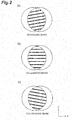
- FIG. 2 includes diagrams illustrating interference fringes formed on the screen 30 of the collimation evaluation device 100 according to the comparative example.
- the interference fringes formed on the screen 30 is a vector sum of a component caused by non-parallelism of the first reflection surface 21 and the second reflection surface 22 of the reflection member 20 and a component caused by non-parallelism of the incident light L 0 .
- the interference fringes formed on the screen 30 include only the component caused by the non-parallelism of the first reflection surface 21 and the second reflection surface 22, and do not include the component caused by the non-parallelism of the incident light L 0 , and for this reason, the interference fringes are parallel to the x axis as illustrated in (b) in FIG. 2 .
- the interference fringes formed on the screen 30 include the component caused by the non-parallelism of the first reflection surface 21 and the second reflection surface 22, and in addition, the component caused by the non-parallelism of the incident light L 0 , and for this reason, the interference fringes are inclined with respect to the x axis as illustrated in (a) and (c) in FIG. 2 .
- the interference fringes ((a) in FIG 2 ) when the incident light L 0 is the diverging light and the interference fringes ((c) in FIG. 2 ) when the incident light L 0 is the converging light inclination directions are opposite to each other.
- the collimation of the incident light L 0 can be evaluated and the collimation of the light L 0 can be adjusted, on the basis of a direction of the interference fringes formed on the screen 30.
- a reference line is drawn on the screen 30 and the interference fringes are parallel to the reference line, it can be determined that the incident light L 0 is the collimated light.
- the thickness of the reflection member 20 it is preferable to increase the thickness of the reflection member 20 to be the shear plate, to detect the change in the direction of the interference fringes with respect to the reference line on the screen 30 with high sensitivity.
- the thickness of the reflection member 20 increases, an optical path difference between the reflected light L 1 and the reflected light L 2 arriving at the screen 30 increases. Meanwhile, when the optical path difference is shorter than the coherence length of the evaluation object light L 0 , the interference fringes can be observed on the screen 30.
- the optical path difference increases and a collimation evaluation of light of which the coherence length is shorter than the optical path difference cannot be performed.
- the collimation evaluation device 100 according to the comparative example it is difficult to evaluate the collimation of the light of which the coherence length is short with high sensitivity.
- FIG. 3 is a diagram illustrating a configuration of a collimation evaluation device 1 according to a first embodiment.
- the collimation evaluation device 1 according to the first embodiment includes a first reflection member 10, a second reflection member 20, a screen 30, and a housing 40.
- the first reflection member 10, the second reflection member 20, and the screen 30 are fixed to the housing 40. It is assumed that a direction where light L 0 of a collimation evaluation object is incident on the collimation evaluation device 1 is parallel to an x axis.
- the first reflection member 10 is a transparent flat plate that has a first reflection surface 11 for reflecting a part of incident light and a second reflection surface 12 for reflecting light transmitted through the first reflection surface 11 in the light.
- the second reflection member 20 is a transparent flat plate that has a first reflection surface 21 for reflecting a part of incident light and a second reflection surface 22 for reflecting light transmitted through the first reflection surface 21 in the light.
- a material of the transparent flat plate is BK7 or synthetic quartz, for example.
- the first reflection member 10 is disposed such that, when light being incident in parallel to the x axis and transmitted through the second reflection member 20 is incident, the first reflection member reflects a part of the light by the first reflection surface 11, reflects the light transmitted through the first reflection surface 11 in the light by the second reflection surface 12, and emits these reflected light components in an opposite direction.
- the second reflection member 20 is disposed such that, when the light emitted from the first reflection member 10 is incident, the second reflection member reflects a part of the light by the first reflection surface 21, reflects the light transmitted through the first reflection surface 21 in the light by the second reflection surface 22, and emits these reflected light components in parallel to a z axis.
- each of the reflection surfaces 11, 12, 21, and 22 Flatness of each of the reflection surfaces 11, 12, 21, and 22 is about a fraction of a wavelength of evaluation object light.
- the first reflection member 10 the first reflection surface 11 and the second reflection surface 12 are parallel to each other.
- the second reflection member 20 is a shear plate in which the first reflection surface 21 and the second reflection surface 22 are non-parallel to each other, a distance between the reflection surfaces changes along a direction parallel to the y axis, and the reflection surfaces form an angle (wedge angle) of about several seconds to several tens of seconds.
- the screen 30 is a ground glass plate that is disposed to be parallel to both of the x axis and the y axis.
- light reflected on the first reflection surface 11 of the first reflection member 10 and the first reflection surface 21 of the second reflection member 20 is represented as L 11 .
- Light reflected on the first reflection surface 11 of the first reflection member 10 and the second reflection surface 22 of the second reflection member 20 is represented as L 12 .
- Light reflected on the second reflection surface 12 of the first reflection member 10 and the first reflection surface 21 of the second reflection member 20 is represented as L 21 .
- light reflected on the second reflection surface 12 of the first reflection member 10 and the second reflection surface 22 of the second reflection member 20 is represented as L 22 .
- These reflected light components L 11 , L 12 , L 21 , and L 22 are incident on the screen 30.
- the screen 30 is an observation unit that enables an observation of the interference fringes.
- a direction of interference fringes caused by non-parallelism of the first reflection surface 21 and the second reflection surface 22 in the second reflection member 20 and a direction of interference fringes caused by non-parallelism of the incident light are different from each other.
- a magnitude relation of the optical path lengths of the reflected light components L 11 , L 12 , L 21 , and L 22 is as follows.
- the optical path lengths of these reflected light components are different according to whether light propagates between the first reflection surface 11 and the second reflection surface 12 of the first reflection member 10, and whether light propagates between the first reflection surface 21 and the second reflection surface 22 of the second reflection member 20. Therefore, as compared with the optical path lengths of the reflected light components L 12 and L 21 , the optical path length of the reflected light component L 11 is short and the optical path length of the reflected light component L 22 is long.
- the optical path lengths of the reflected light components L 12 and L 21 can be set almost equally and an optical path difference between the reflected light components L 12 and L 21 can be set to be smaller than the coherence length. That is, the interference fringes can be formed on the screen 30 by the light L 12 reflected on the first reflection surface 11 of the first reflection member 10 and the second reflection surface 22 of the second reflection member 20 and the light L 21 reflected on the second reflection surface 12 of the first reflection member 10 and the first reflection surface 21 of the second reflection member 20.
- the incident light is the collimated light, and by inclinations of the interference fringes with respect to the reference line, it can be determined that the incident light is diverging light or converging light.
- a collimation evaluation method observes the interference fringes formed by the reflected light component L 12 and the reflected light component L 21 on the screen 30 on which the light components are incident, using the first reflection member 10, the second reflection member 20, and the screen 30 described above, and evaluates the collimation of the incident light on the basis of the direction of the observed interference fringes.
- the optical path difference between the reflected light components L 12 and L 21 can be set to be smaller than the coherence length, and therefore, the collimation of the light can be evaluated with high sensitivity.
- the collimation evaluation device 1 according to this embodiment corresponds to the case in which the first reflection member 10 for optical path difference correction is added to the same configuration (that is, the configuration including the second reflection member 20, the screen 30, and the housing 40) as the configuration of the collimation evaluation device 100 according to the comparative example and the incident direction of the evaluation object light is reversed.
- the collimation evaluation device 1 according to the embodiment can be configured by attaching the first reflection member 10 for optical path difference correction to the commercially available collimation evaluation device.
- attachment methods there are a method of attaching the first reflection member 10 to a housing of the commercially available collimation evaluation device by an adhesive or an adhesive tape, a method of attaching the first reflection member 10 to the housing of the commercially available collimation evaluation device by a holder having an adjustment mechanism, and a method of removably attaching the first reflection member 10 to the housing of the commercially available collimation evaluation device by a magnet.
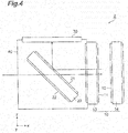
- FIG. 4 is a diagram illustrating a configuration of a collimation evaluation device 2 according to a second embodiment.
- the collimation evaluation device 2 according to the second embodiment illustrated in FIG. 4 is different from the collimation evaluation device 1 according to the first embodiment illustrated in FIG. 3 in a configuration of a first reflection member 10.
- the first reflection member 10 includes a first flat plate 13 that has a first reflection surface 11 and a second flat plate 14 that is disposed in parallel to the first flat plate 13 and has a second reflection surface 12.
- the first reflection surface 11 of the first flat plate 13 and the second reflection surface 12 of the second flat plate 14 face each other and are parallel to each other.
- a reflection reduction film is preferably formed on a surface opposite to the first reflection surface 11 of the first flat plate 13.
- a reflection reduction film is preferably formed on a surface opposite to the second reflection surface 12 of the second flat plate 14.
- a distance between the first flat plate 13 and the second flat plate 14, that is, a distance between the first reflection surface 11 and the second reflection surface 12 is preferably variable. In this way, an optical path difference of reflected light components L 12 and L 21 incident on the screen 30 can be adjusted, and the optical path difference can be set according to a coherence length of the light.
- a movement mechanism for moving both or one of the first flat plate 13 and the second flat plate 14 in a direction parallel to the x axis may be provided.
- a stage having high position precision or an annular shim is preferably used as the movement mechanism.
- FIG. 5 and FIG. 6 include photographs of interference fringes observed on the screen 30 of the collimation evaluation device 2 according to the second embodiment.
- Light of a collimation evaluation object is laser light emitted from an optical fiber end face of an optical fiber laser light source and having a wavelength of 1080 nm and a coherence length of 0.6 mm and is incident on the collimation evaluation device 2 via a lens.
- the distance between the first flat plate 13 and the second flat plate 14 (that is, the distance between the first reflection surface 11 and the second reflection surface 12) is changed continuously by 0.20 mm in a range of 2.95 mm to 3.95 mm and interference fringes formed on the screen 30 in the case of each distance are photographed.
- FIG. 5 is a photograph of interference fringes in the case of a distance of 2.95 mm
- (b) in FIG 5 is a photograph of interference fringes in the case of a distance of 3.15 mm
- (c) in FIG. 5 is a photograph of interference fringes in the case of a distance of 3.35 mm
- (a) in FIG. 6 is a photograph of interference fringes in the case of a distance of 3.55 mm
- (b) in FIG 6 is a photograph of interference fringes in the case of a distance of 3.75 mm
- (c) in FIG. 6 is a photograph of interference fringes in the case of a distance of 3.95 mm.
- the optical path difference of the reflected light components L 12 and L 21 incident on the screen 30 can be minimized and contrast of the interference fringes is most favorable.
- the contrast of the interference fringes is deteriorated.
- the distance between the first flat plate 13 and the second flat plate 14 of the first reflection member 10 is set according to the thickness of the second reflection member 20, such that the optical path difference of the reflected light components L 12 and L 21 generated at the time of reflection in the first reflection member 10 and the optical path difference of the reflected light components L 12 and L 21 generated at the time of reflection in the second reflection member 20 are canceled.
- the distance between the first flat plate 13 and the second flat plate 14 is appropriately set, so that the optical path difference between the reflected light components L 12 and L 21 can be set to be smaller than the coherence length, and therefore, collimation of the light can be evaluated with high sensitivity.
- FIG 7 is a diagram illustrating a configuration of a collimation evaluation device 3 according to a third embodiment.
- the collimation evaluation device 3 according to the third embodiment includes a first reflection member 10, a second reflection member 20, a screen 30, and a housing 40.
- the first reflection member 10, the second reflection member 20, and the screen 30 are fixed to the housing 40. It is assumed that a direction where light of a collimation evaluation object is incident on the collimation evaluation device 3 is parallel to a z axis.
- the first reflection member 10, the second reflection member 20, and the screen 30 according to the third embodiment are the same as those in the first embodiment, except for an arrangement thereof.
- the first reflection member 10 is disposed such that, when light is incident in parallel to the z axis, the first reflection member reflects a part of the light by a first reflection surface 11, reflects light transmitted through the first reflection surface 11 in the light by a second reflection surface 12, and emits these reflected light components in a direction parallel to an x axis.
- the second reflection member 20 is disposed such that, when the light emitted from the first reflection member 10 is incident, the second reflection member reflects a part of the light by a first reflection surface 21, reflects light transmitted through the first reflection surface 21 in the light by a second reflection surface 22, and emits these reflected light components in parallel to the z axis.
- the screen 30 is a ground glass plate that is disposed to be parallel to both of the x axis and the y axis. Reflected light components L 11 , L 12 , L 21 , and L 22 are incident on the screen 30. Even in this embodiment, when a thickness of each of the first reflection member 10 and the second reflection member 20 is appropriately set, optical path lengths of the reflected light components L 12 and L 21 can be set almost equally and an optical path difference between the reflected light components L 12 and L 21 can be set to be smaller than a coherence length.
- interference fringes can be formed on the screen 30 by the light L 12 reflected on the first reflection surface 11 of the first reflection member 10 and the second reflection surface 22 of the second reflection member 20 and the light L 21 reflected on the second reflection surface 12 of the first reflection member 10 and the first reflection surface 21 of the second reflection member 20.
- the optical path difference of the reflected light components L 12 and L 21 can be set to be smaller than the coherence length, and therefore, collimation of the light can be evaluated with high sensitivity.
- the evaluation object light is incident on the first reflection member 10 after being transmitted through the second reflection member 20, the light is lost at the time of transmission in the second reflection member 20.
- the evaluation object light can be directly incident on the first reflection member 10 without transmission in the second reflection member 20, there is no loss due to transmission in the second reflection member 20.
- FIG. 8 is a diagram illustrating a configuration of a collimation evaluation device 4 according to a fourth embodiment.
- the collimation evaluation device 4 according to the fourth embodiment illustrated in FIG. 8 is different from the collimation evaluation device 3 according to the third embodiment illustrated in FIG. 7 in an arrangement of a first reflection member 10.
- the first reflection surface 11 and the second reflection surface 12 are disposed to be inclined to both the x axis and the z axis by 45 degrees and both an incident angle and a reflection angle of light are 45 degrees.
- the first reflection surface 11 and the second reflection surface 12 are disposed to be rotatable about an axis parallel to the y axis, and an incident angle and an emission angle of the light are variable.
- a direction of light incident on the first reflection member 10 is set such that light reflected on the first reflection member 10 is emitted in parallel to the x axis.
- a direction of the first reflection member 10 is adjusted according to a thickness of the second reflection member 20, such that an optical path difference of reflected light components L 12 and L 21 generated at the time of reflection in the first reflection member 10 and an optical path difference of reflected light components L 12 and L 21 generated at the time of reflection in the second reflection member 20 are canceled.
- the direction of the first reflection member 10 is adjusted, so that the optical path difference of the reflected light components L 12 and L 21 generated at the time of the reflection in the first reflection member 10 can be adjusted.
- the direction of the first reflection member 10 is adjusted, so that the optical path difference between the reflected light components L 12 and L 21 can be set to be smaller than the coherence length, and therefore, collimation of the light can be evaluated with high sensitivity.
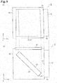
- FIG. 9 includes diagrams illustrating a configuration of a collimation evaluation device 5 according to a fifth embodiment.
- (a) in FIG. 9 is a top view when viewed from a direction parallel to a z axis (direction vertical to a screen 30).
- (b) in FIG. 9 is a side view when viewed from a direction parallel to a y axis.
- illustration of the screen 30 is omitted.
- the collimation evaluation device 5 according to the fifth embodiment illustrated in FIG 9 is different from the collimation evaluation device 1 according to the first embodiment illustrated in FIG. 3 in a configuration of a first reflection member 10.
- the first reflection surface 11 and the second reflection surface 12 of the first reflection member 10 are parallel to each other.
- the first reflection surface 11 and the second reflection surface 12 of the first reflection member 10 are non-parallel to each other, a distance between the reflection surfaces changes along one direction, and the reflection surfaces form an angle (wedge angle) of about several seconds to several tens of seconds. That is, in the fifth embodiment, both of the first reflection member 10 and the second reflection member 20 are shear plates.
- the first reflection member 10 is preferably disposed to be rotatable about an axis perpendicular to an x axis.
- FIG. 10 and FIG 11 include diagrams illustrating an example of a function of the collimation evaluation device 5 according to the fifth embodiment.
- (a) in FIG 10 and (a) in FIG. 11 are each a top view of the collimation evaluation device 5 according to the fifth embodiment.
- (b) in FIG 10 and (b) in FIG. 11 are each a diagram illustrating interference fringes observed in the case of (a) in the corresponding figure. In these drawings, illustration of the screen 30 is omitted.
- a distance between the first reflection surface 21 and the second reflection surface 22 decreases toward a +y direction.
- the interference fringe spacing depends on a sum of wedge angles of the first reflection member 10 and the second reflection member 20 and depends on a wavelength of light of a collimation evaluation object.
- a total wedge angle in the case in which the wedge directions of the first reflection member 10 and the second reflection member 20 are opposite to each other becomes 2 ⁇ 2 /3.
- a total wedge angle in the case in which the wedge directions of the first reflection member 10 and the second reflection member 20 are equal to each other becomes 4 ⁇ 2 /3, and becomes twice the total wedge angle in the case in which the wedge directions are opposite to each other.
- the spacing of the interference fringes can be set equally in both of the cases.
- FIG. 12 and FIG. 13 include diagrams illustrating another example of a function of the collimation evaluation device 5 according to the fifth embodiment.
- (a) in FIG. 12 and (a) in FIG. 13 are each a top view of the collimation evaluation device 5 according to the fifth embodiment.
- (b) in FIG. 12 and (b) in FIG. 13 are each a diagram illustrating interference fringes observed in the case of (a) in the corresponding figure.
- illustration of the screen 30 is omitted, however, a reference line A drawn on the screen 30 is shown.
- a distance between the first reflection surface 21 and the second reflection surface 22 decreases toward the approximately +y direction, however, because precision of attachment to the housing 40 or the like is insufficient, the wedge direction is inclined slightly from the y direction.
- FIG. 14 includes photographs of interference fringes observed on the screen 30 of the collimation evaluation device 5 according to the fifth embodiment.
- Light of the collimation evaluation object is laser light emitted from an optical fiber end face of an optical fiber laser light source and having a wavelength of 1080 nm and a coherence length of 0.6 mm, and is incident on the collimation evaluation device 5 via a lens.
- the wedge direction of the first reflection member 10 is changed continuously by 90 degrees and interference fringes formed on the screen 30 in the case of each wedge direction are photographed.
- FIG. 14 illustrates interference fringes when the wedge direction of the first reflection member 10 is rotated by 90 degrees
- FIG. 14 illustrates interference fringes when the wedge direction of the first reflection member 10 is rotated by 180 degrees.
- the present invention is not limited to the embodiments described above and various modifications can be made.
- the transmission-type screen 30 made of the ground glass plate is used as the observation unit to enable the interference fringes formed by the reflected light components L 12 and L 21 to be observed and the interference fringes are observed by the light transmitted and diffused through the screen 30.
- the observation unit to enable the interference fringes to be observed is not limited thereto.
- FIG. 15 to FIG. 18 are diagrams illustrating configurations of modifications of the collimation evaluation device 1 according to the first embodiment. In these modifications, other configuration is adopted as the observation unit to enable the interference fringes to be observed.
- a collimation evaluation device 1A according to a first modification illustrated in FIG. 15 uses a reflection-type screen 31 as an observation unit and observes interference fringes by light reflected and diffused by the screen 30.
- the device is suitable from the viewpoint of safety of an observer, when interference fringes of light having high intensity are observed.
- a collimation evaluation device 1B according to a second modification illustrated in FIG. 16 uses a camera 32 as an observation unit, displays interference fringes imaged by the camera 32 on a display device, and observes the interference fringes.
- a camera 32 as an observation unit
- displays interference fringes imaged by the camera 32 on a display device and observes the interference fringes.
- the interference fringes can be observed.
- a collimation evaluation device 1C according to a third modification illustrated in FIG. 17 uses a lens 33 and a camera 32 as an observation unit, images interference fringes enlarged or reduced by the lens 33 by the camera 32, displays the imaged interference fringes on a display device, and observes the interference fringes.
- the interference fringes can be observed, and further, the interference fringes can be observed in a desired field of view by changing magnification.
- a collimation evaluation device 1D according to a fourth modification illustrated in FIG. 18 uses a transmission-type screen 30, a lens 33, and a camera 32 as an observation unit, enlarges or reduces interference fringes on the screen 30 by the lens 33, images the interference fringes by the camera 32, displays the imaged interference fringes on a display device, and observes the interference fringes.
- the interference fringes can be observed, and further, the interference fringes of desired spacing can be observed by changing magnification.
- inclinations of the interference fringes with respect to a reference line drawn on the screen 30 can be confirmed.
- the collimation evaluation devices 1B and 1C not using the screen cannot use the reference line on the screen, however, an electron line of the camera 32 can be used as the reference line.
- collimation evaluation devices 1A to 1D are the modifications of the collimation evaluation device 1 according to the first embodiment, however, the same modifications can be made in the collimation evaluation devices 2 to 5 according to the other embodiments.
- the first reflection surface 11 and the second reflection surface 12 of the first reflection member 10 are parallel to each other and the first reflection surface 21 and the second reflection surface 22 of the second reflection member 20 are non-parallel to each other.
- the first reflection surface 11 and the second reflection surface 12 of the first reflection member 10 may be non-parallel to each other and the first reflection surface 21 and the second reflection surface 22 of the second reflection member 20 may be parallel to each other.
- the first reflection surface and the second reflection surface may be non-parallel to each other.
- the first reflection member 10 and the second reflection member 20 are disposed such that the direction of the interference fringes caused by the non-parallelism of the first reflection surface and the second reflection surface in both or one of the first reflection member 10 and the second reflection member 20 and the direction of the interference fringes caused by the non-parallelism of the incident light are different from each other. Then, the interference fringes formed by the light L 12 reflected on the first reflection surface 11 of the first reflection member 10 and the second reflection surface 22 of the second reflection member 20 and the light L 21 reflected on the second reflection surface 12 of the first reflection member 10 and the first reflection surface 21 of the second reflection member 20 are observed, so that the collimation of the incident light can be evaluated on the basis of the direction of the observed interference fringes.
- the first reflection member 10 is configured using the two flat plates
- the second reflection member 20 may also be configured using the two flat plates. This is applicable to the other embodiments.
- the distance between the two flat plates is adjusted, so that the optical path difference of the reflected light components L 12 and L 21 can be adjusted.
- the inclinations of both or one of the two flat plates are adjusted, so that the wedge angle or the wedge direction of the reflection member can be adjusted.
- the collimation evaluation device is configured to include: (1) a first reflection member having a first reflection surface for reflecting a part of incident light and a second reflection surface for reflecting light transmitted through the first reflection surface in the incident light; and (2) a second reflection member having a first reflection surface for reflecting a part of light emitted from the first reflection member and a second reflection surface for reflecting light transmitted through the first reflection surface in the light, and (3) collimation of the incident light is evaluated on the basis of a direction of interference fringes formed by a light component reflected on the first reflection surface of the first reflection member and the second reflection surface of the second reflection member and a light component reflected on the second reflection surface of the first reflection member and the first reflection surface of the second reflection member.
- the collimation evaluation method is configured to include: (1) using a first reflection member having a first reflection surface for reflecting a part of incident light and a second reflection surface for reflecting light transmitted through the first reflection surface in the incident light, and (2) a second reflection member having a first reflection surface for reflecting a part of light emitted from the first reflection member and a second reflection surface for reflecting light transmitted through the first reflection surface in the light; (a) observing interference fringes formed by a light component reflected on the first reflection surface of the first reflection member and the second reflection surface of the second reflection member and a light component reflected on the second reflection surface of the first reflection member and the first reflection surface of the second reflection member; and (b) evaluating collimation of the incident light on the basis of a direction of the observed interference fringes.
- the first reflection surface and the second reflection surface are non-parallel to each other in both or one of the first reflection member and the second reflection member, and a direction of interference fringes caused by non-parallelism of the first reflection surface and the second reflection surface in both or one of the first reflection member and the second reflection member and a direction of interference fringes caused by non-parallelism of the incident light are different from each other.
- the first reflection surface and the second reflection surface are non-parallel to each other in both or one of the first reflection member and the second reflection member, and the first reflection member and the second reflection member are disposed such that a direction of interference fringes caused by non-parallelism of the first reflection surface and the second reflection surface in both or one of the first reflection member and the second reflection member and a direction of interference fringes caused by non-parallelism of the incident light are different from each other.
- both or one of the first reflection member and the second reflection member may include a flat plate having two surfaces opposite to each other as the first reflection surface and the second reflection surface.
- both or one of the first reflection member and the second reflection member may include a first flat plate having the first reflection surface and a second flat plate being disposed in parallel to the first flat plate and having the second reflection surface.
- a distance between the first flat plate and the second flat plate (that is, a distance between the first reflection surface and the second reflection surface) is variable.
- the first reflection surface and the second reflection surface may be non-parallel to each other in both of the first reflection member and the second reflection member, and both or one of the first reflection member and the second reflection member may be rotatable about an axis substantially perpendicular to the first reflection surface or the second reflection surface.
- the spacing of the interference fringes can be adjusted by adjusting a rotation position of the first reflection member or the second reflection member. Further, even when precision of attachment of one reflection member of the first reflection member and the second reflection member is insufficient, collimation of the incident light can be evaluated accurately by adjusting a rotation position of the other reflection member.
- coating for reducing reflectance to reduce signal intensity may be provided on the reflection surfaces 21 and 22, or the reflection surfaces 11 and 12, or the four surfaces of the reflection surfaces 21, 22, 11, and 12. Further, in this case, reflectance of the reflection surfaces 21 and 22 and reflectance of the reflection surfaces 11 and 12 are preferably set to almost the same reflectance to obtain favorable contrast in the generated interference fringes.
- the coating a total of two layers including individual layers of aluminum oxide Al 2 O 3 and magnesium fluoride MgF 2 are laminated, so that reflectance of about 1% can be realized on a glass surface and a glass rear surface.
- the present invention can be used as a device and a method that can evaluate collimation of light of a collimation evaluation object with high sensitivity, even when a coherence length of the light is short.
- 1 to 5 - collimation evaluation device 10 - first reflection member, 11 - first reflection surface, 12 - second reflection surface, 20 - second reflection member, 21 - first reflection surface, 22- second reflection surface, 30, 31 - screen, 32 - camera, 33 - lens, 40 - housing.
Landscapes
- Physics & Mathematics (AREA)
- Spectroscopy & Molecular Physics (AREA)
- General Physics & Mathematics (AREA)
- Chemical & Material Sciences (AREA)
- Analytical Chemistry (AREA)
- Instruments For Measurement Of Length By Optical Means (AREA)
- Testing Of Optical Devices Or Fibers (AREA)
- Length Measuring Devices By Optical Means (AREA)
Description
- The present invention relates to a device and a method for evaluating collimation of light.
- Kuppuswamy Venkatesan Sriram et al is about "Double-Wedge-Plate Interferometer For Collimation Testing: New Configurations" published in Applied Optics, Optical Society Of America, Washington, DC; US, (19930801), Vol. 32, No. 22, ISSN 0003-6935, Pages 4199 - 4203. Staub F et al is about "Collimation tester for ultrashort pulses and short coherence length lasers", published in Optik, Wissenschaftliche Verlag GmbH, DE, vol. 117, no. 4, (20060403), pages 193 - 195. Choi J et al is about "Wedge-Plate Shearing Interferometers For Collimation Testing: Use Of A Moire Technique", Applied Optics, Optical Society Of America, Washington, DC; US, (19950701), vol. 34, no. 19, pages 3628 - 3638. In various optical systems, the frequency of converting (collimating) diverging light emitted from a point light source (including a light source regarded as the point light source) into parallel light is high. As examples of the point light source, there are a laser diode and an optical fiber emission end. A distance between the point light source and a collimation optical system is appropriately set, so that the diverging light emitted from the point light source can be converted into the parallel light by the collimation optical system. Technologies for evaluating a degree of parallelization (degree of collimation) of the parallel light generated as described above are described in
Patent Documents - In particular, according to the technology described in
Patent Document 1, collimation of light can be easily evaluated using a shear plate having a first reflection surface and a second reflection surface which are non-parallel to each other. That is, a collimation evaluation device using the shear plate causes light reflected on the first reflection surface of the shear plate and light transmitted through the first reflection surface of the shear plate and being reflected on the second reflection surface to interfere with each other on a screen, and can evaluate collimation of the light on the basis of a direction of interference fringes on the screen. The shear plate may be called a shearing plate. -
- Patent Document 1: Japanese Patent Application Laid-Open Publication No.
2001-336914 - Patent Document 2: Japanese Patent Publication No.
4114847 - In the collimation evaluation device using the shear plate described above, it is demanded to increase a thickness of the shear plate and decrease an angle (wedge angle) formed by the two reflection surfaces of the shear plate, for detecting a change in the direction of the interference fringes on the screen with high sensitivity. In particular, because the wedge angle affects the spacing of the interference fringes, the wedge angle is determined to some degree by the interference fringe spacing suitable for a collimation evaluation. Therefore, the thickness of the shear plate is increased for improving sensitivity.
- An optical path difference is generated between light components until the light components are reflected on the two reflection surfaces of the shear plate and arrive at the screen. When the thickness of the shear plate increases, the optical path difference increases. Meanwhile, when the optical path difference is smaller than a coherence length of light of a collimation evaluation object, the interference fringes can be observed on the screen.
- For example, CW laser light output from a HeNe laser light source has a coherence length of the order of 100 mm. Pulse laser light output from a solid-state laser light source with a pulse width of 40 ns has a coherence length of several mm. Further, pulse laser light output from an optical fiber laser light source with a pulse width of 40 ns has a coherence length of 1 mm or less. In general, laser light of a short pulse output from the solid-state laser light source or the optical fiber laser light source has a short coherence length due to a multi longitudinal mode or spectral broadening.
- When the thickness of the shear plate is increased to improve the sensitivity, the optical path difference increases, and a collimation evaluation of light of which a coherence length is shorter than the optical path difference cannot be performed. As described above, conventionally, in the collimation evaluation device using the shear plate, it is difficult to evaluate collimation of light of which a coherence length is short with high sensitivity.
- The present invention has been made to solve the above problem, and an object thereof is to provide a device and a method that can evaluate collimation of light of a collimation evaluation object with high sensitivity, even when a coherence length of the light is short.
- A collimation evaluation device according to the present invention is defined in
claim 1. - A collimation evaluation method according to the present invention is defined in claim 7. Further advantageous embodiments are defined in the dependent claims.
- In the collimation evaluation device or the collimation
evaluation method described above, light of a collimation evaluation object is first incident on the first reflection member, a part of the light is reflected on the first reflection surface of the first reflection member, and light transmitted through the first reflection surface is reflected on the second reflection surface of the first reflection member. Light reflected on the first reflection member is then incident on the second reflection member, a part of the light is reflected on the first reflection surface of the second reflection member, and light transmitted through the first reflection surface is reflected on the second reflection surface of the second reflection member. - In these reflected light components, an optical path difference between light L12 reflected on the first reflection surface of the first reflection member and the second reflection surface of the second reflection member and light L21 reflected on the second reflection surface of the first reflection member and the first reflection surface of the second reflection member can be set to be smaller than a coherence length, and therefore, interference fringes caused by the two light components L12 and L21 can be observed. Collimation of the incident light can be evaluated on the basis of a direction of the observed interference fringes.
- According to the present invention, even when a coherence length of light of a collimation evaluation object is short, collimation of the light can be evaluated with high sensitivity.
-
-
FIG. 1 is a diagram illustrating a configuration of acollimation evaluation device 100 according to a comparative example. -
FIG. 2 includes (a) - (c) diagrams illustrating interference fringes formed on ascreen 30 of thecollimation evaluation device 100 according to the comparative example. -
FIG. 3 is a diagram illustrating a configuration of acollimation evaluation device 1 according to a first embodiment. -
FIG. 4 is a diagram illustrating a configuration of acollimation evaluation device 2 according to a second embodiment. -
FIG. 5 includes (a) - (c) photographs of interference fringes observed on ascreen 30 of thecollimation evaluation device 2 according to the second embodiment. -
FIG. 6 includes (a) - (c) photographs of interference fringes observed on thescreen 30 of thecollimation evaluation device 2 according to the second embodiment. -
FIG 7 is a diagram illustrating a configuration of acollimation evaluation device 3 according to a third embodiment not part of the invention. -
FIG 8 is a diagram illustrating a configuration of acollimation evaluation device 4 according to a fourth embodiment not part of the invention. -
FIG. 9 includes (a), (b) diagrams illustrating a configuration of acollimation evaluation device 5 according to a fifth embodiment. -
FIG. 10 includes (a), (b) diagrams illustrating an example of a function of thecollimation evaluation device 5 according to the fifth embodiment. -
FIG. 11 includes (a), (b) diagrams illustrating the example of the function of thecollimation evaluation device 5
according to the fifth embodiment. -
FIG 12 includes (a), (b) diagrams illustrating another example of a function of thecollimation evaluation device 5 according to the fifth embodiment. -
FIG 13 includes (a), (b) diagrams illustrating the other example of the function of thecollimation evaluation device 5 according to the fifth embodiment. -
FIG. 14 includes (a) - (c) photographs of interference fringes observed on thescreen 30 of thecollimation evaluation device 5 according to the fifth embodiment. -
FIG. 15 is a diagram illustrating a configuration of a first modification of the collimation evaluation device according to the first embodiment. -
FIG. 16 is a diagram illustrating a configuration of a second modification of the collimation evaluation device according to the first embodiment. -
FIG. 17 is a diagram illustrating a configuration of a third modification of the collimation evaluation device according to the first embodiment. -
FIG. 18 is a diagram illustrating a configuration of a fourth modification of the collimation evaluation device according to the first embodiment. - Hereinafter, embodiments of the present invention will be described in detail with reference to the accompanying drawings. In the description of the drawings, the same elements will be denoted by the same reference signs, without redundant description. In addition, a xyz orthogonal coordinate system is illustrated in the individual drawings for the convenience of the description.
-
FIG. 1 is a diagram illustrating a configuration of acollimation evaluation device 100 according to a comparative example. Thecollimation evaluation device 100 according to the comparative example includes areflection member 20, ascreen 30, and ahousing 40. Thereflection member 20 and thescreen 30 are fixed to thehousing 40. It is assumed that a direction where light L0 of a collimation evaluation object is incident into thecollimation evaluation device 100 is parallel to an x axis. - The
reflection member 20 is a shear plate made of a transparent flat plate that has afirst reflection surface 21 and asecond reflection surface 22 opposite to each other. A material of the transparent flat plate is, for example, BK7 or synthetic quartz. Thereflection member 20 is disposed to reflect the light L0 incident in parallel to the x axis and emit the reflected light in parallel to a z axis. Flatness of thefirst reflection surface 21 and thesecond reflection surface 22 is about a fraction of a wavelength of evaluation object light. Thefirst reflection surface 21 and thesecond reflection surface 22 are non-parallel to each other, a distance between the reflection surfaces changes along a direction parallel to a y axis, and the surfaces form an angle (wedge angle) of about several seconds to several tens of seconds. - The
screen 30 is a ground glass plate that is disposed to be parallel to both of the x axis and the y axis. Reflected light components L1 and L2 that are respectively reflected on thefirst reflection surface 21 and thesecond reflection surface 22 of thereflection member 20 are incident on thescreen 30. Interference fringes are formed on thescreen 30 by the two light components L1 and L2, and the interference fringes can be observed. - In the
collimation evaluation device 100, the evaluation object light L0 is incident on thereflection member 20 in parallel to the x axis. A part of the incident light L0 is reflected on thefirst reflection surface 21 and the reflected light L1 thereof is incident on thescreen 30 in parallel to the z axis. In the incident light L0, light transmitted through thefirst reflection surface 21 is reflected on thesecond reflection surface 22 and the reflected light L2 thereof is incident on thescreen 30 in parallel to the z axis. The reflected light component L1 and the reflected light component L2 incident on thescreen 30 are shifted in a direction parallel to the x axis by a distance according to a thickness of thereflection member 20 and an optical path difference according to the thickness of thereflection member 20 is generated. -
FIG. 2 includes diagrams illustrating interference fringes formed on thescreen 30 of thecollimation evaluation device 100 according to the comparative example. The interference fringes formed on thescreen 30 is a vector sum of a component caused by non-parallelism of thefirst reflection surface 21 and thesecond reflection surface 22 of thereflection member 20 and a component caused by non-parallelism of the incident light L0. - When the incident light L0 is collimated light, the interference fringes formed on the
screen 30 include only the component caused by the non-parallelism of thefirst reflection surface 21 and thesecond reflection surface 22, and do not include the component caused by the non-parallelism of the incident light L0, and for this reason, the interference fringes are parallel to the x axis as illustrated in (b) inFIG. 2 . - When the incident light L0 is diverging light or converging light, the interference fringes formed on the
screen 30 include the component caused by the non-parallelism of thefirst reflection surface 21 and thesecond reflection surface 22, and in addition, the component caused by the non-parallelism of the incident light L0, and for this reason, the interference fringes are inclined with respect to the x axis as illustrated in (a) and (c) inFIG. 2 . In the interference fringes ((a) inFIG 2 ) when the incident light L0 is the diverging light and the interference fringes ((c) inFIG. 2 ) when the incident light L0 is the converging light, inclination directions are opposite to each other. - As such, the collimation of the incident light L0 can be evaluated and the collimation of the light L0 can be adjusted, on the basis of a direction of the interference fringes formed on the
screen 30. When a reference line is drawn on thescreen 30 and the interference fringes are parallel to the reference line, it can be determined that the incident light L0 is the collimated light. - In the
collimation evaluation device 100 according to the comparative example described above, it is preferable to increase the thickness of thereflection member 20 to be the shear plate, to detect the change in the direction of the interference fringes with respect to the reference line on thescreen 30 with high sensitivity. However, when the thickness of thereflection member 20 increases, an optical path difference between the reflected light L1 and the reflected light L2 arriving at thescreen 30 increases. Meanwhile, when the optical path difference is shorter than the coherence length of the evaluation object light L0, the interference fringes can be observed on thescreen 30. - When the thickness of the
reflection member 20 is increased to improve the sensitivity, the optical path difference increases and a collimation evaluation of light of which the coherence length is shorter than the optical path difference cannot be performed. As such, in thecollimation evaluation device 100 according to the comparative example, it is difficult to evaluate the collimation of the light of which the coherence length is short with high sensitivity. -
FIG. 3 is a diagram illustrating a configuration of acollimation evaluation device 1 according to a first embodiment. Thecollimation evaluation device 1 according to the first embodiment includes afirst reflection member 10, asecond reflection member 20, ascreen 30, and ahousing 40. Thefirst reflection member 10, thesecond reflection member 20, and thescreen 30 are fixed to thehousing 40. It is assumed that a direction where light L0 of a collimation evaluation object is incident on thecollimation evaluation device 1 is parallel to an x axis. - The
first reflection member 10 is a transparent flat plate that has afirst reflection surface 11 for reflecting a part of incident light and asecond reflection surface 12 for reflecting light transmitted through thefirst reflection surface 11 in the light. Thesecond reflection member 20 is a transparent flat plate that has afirst reflection surface 21 for reflecting a part of incident light and asecond reflection surface 22 for reflecting light transmitted through thefirst reflection surface 21 in the light. A material of the transparent flat plate is BK7 or synthetic quartz, for example. - The
first reflection member 10 is disposed such that, when light being incident in parallel to the x axis and transmitted through thesecond reflection member 20 is incident, the first reflection member reflects a part of the light by thefirst reflection surface 11, reflects the light transmitted through thefirst reflection surface 11 in the light by thesecond reflection surface 12, and emits these reflected light components in an opposite direction. Thesecond reflection member 20 is disposed such that, when the light emitted from thefirst reflection member 10 is incident, the second reflection member reflects a part of the light by thefirst reflection surface 21, reflects the light transmitted through thefirst reflection surface 21 in the light by thesecond reflection surface 22, and emits these reflected light components in parallel to a z axis. - Flatness of each of the reflection surfaces 11, 12, 21, and 22 is about a fraction of a wavelength of evaluation object light. In the
first reflection member 10, thefirst reflection surface 11 and thesecond reflection surface 12 are parallel to each other. Thesecond reflection member 20 is a shear plate in which thefirst reflection surface 21 and thesecond reflection surface 22 are non-parallel to each other, a distance between the reflection surfaces changes along a direction parallel to the y axis, and the reflection surfaces form an angle (wedge angle) of about several seconds to several tens of seconds. - The
screen 30 is a ground glass plate that is disposed to be parallel to both of the x axis and the y axis. Here, light reflected on thefirst reflection surface 11 of thefirst reflection member 10 and thefirst reflection surface 21 of thesecond reflection member 20 is represented as L11. Light reflected on thefirst reflection surface 11 of thefirst reflection member 10 and thesecond reflection surface 22 of thesecond reflection member 20 is represented as L12. Light reflected on thesecond reflection surface 12 of thefirst reflection member 10 and thefirst reflection surface 21 of thesecond reflection member 20 is represented as L21. Further, light reflected on thesecond reflection surface 12 of thefirst reflection member 10 and thesecond reflection surface 22 of thesecond reflection member 20 is represented as L22. These reflected light components L11, L12, L21, and L22 are incident on thescreen 30. - On the
screen 30, the components having optical path differences shorter than a coherence length among these reflected light components L11, L12, L21, and L22 interfere with each other, and thus, interference fringes are formed, and the interference fringes can be observed. Thescreen 30 is an observation unit that enables an observation of the interference fringes. A direction of interference fringes caused by non-parallelism of thefirst reflection surface 21 and thesecond reflection surface 22 in thesecond reflection member 20 and a direction of interference fringes caused by non-parallelism of the incident light are different from each other. - A magnitude relation of the optical path lengths of the reflected light components L11, L12, L21, and L22 is as follows. The optical path lengths of these reflected light components are different according to whether light propagates between the
first reflection surface 11 and thesecond reflection surface 12 of thefirst reflection member 10, and whether light propagates between thefirst reflection surface 21 and thesecond reflection surface 22 of thesecond reflection member 20. Therefore, as compared with the optical path lengths of the reflected light components L12 and L21, the optical path length of the reflected light component L11 is short and the optical path length of the reflected light component L22 is long. - When the thickness of each of the
first reflection member 10 and thesecond reflection member 20 is appropriately set, the optical path lengths of the reflected light components L12 and L21 can be set almost equally and an optical path difference between the reflected light components L12 and L21 can be set to be smaller than the coherence length. That is, the interference fringes can be formed on thescreen 30 by the light L12 reflected on thefirst reflection surface 11 of thefirst reflection member 10 and thesecond reflection surface 22 of thesecond reflection member 20 and the light L21 reflected on thesecond reflection surface 12 of thefirst reflection member 10 and thefirst reflection surface 21 of thesecond reflection member 20. - When a reference line is drawn on the
screen 30 and the interference fringes are parallel to the reference line, it can be determined that the incident light is the collimated light, and by inclinations of the interference fringes with respect to the reference line, it can be determined that the incident light is diverging light or converging light. - A collimation evaluation method according to this embodiment observes the interference fringes formed by the reflected light component L12 and the reflected light component L21 on the
screen 30 on which the light components are incident, using thefirst reflection member 10, thesecond reflection member 20, and thescreen 30 described above, and evaluates the collimation of the incident light on the basis of the direction of the observed interference fringes. - In this embodiment, even when the thickness of the
second reflection member 20 is large to improve the sensitivity, and the coherence length of the light of the collimation evaluation object is short, the optical path difference between the reflected light components L12 and L21 can be set to be smaller than the coherence length, and therefore, the collimation of the light can be evaluated with high sensitivity. - The
collimation evaluation device 1 according to this embodiment corresponds to the case in which thefirst reflection member 10 for optical path difference correction is added to the same configuration (that is, the configuration including thesecond reflection member 20, thescreen 30, and the housing 40) as the configuration of thecollimation evaluation device 100 according to the comparative example and the incident direction of the evaluation object light is reversed. - Therefore, if there is a commercially available collimation evaluation device having the same configuration as the configuration of the
collimation evaluation device 100 according to the comparative example, thecollimation evaluation device 1 according to the embodiment can be configured by attaching thefirst reflection member 10 for optical path difference correction to the commercially available collimation evaluation device. As attachment methods, there are a method of attaching thefirst reflection member 10 to a housing of the commercially available collimation evaluation device by an adhesive or an adhesive tape, a method of attaching thefirst reflection member 10 to the housing of the commercially available collimation evaluation device by a holder having an adjustment mechanism, and a method of removably attaching thefirst reflection member 10 to the housing of the commercially available collimation evaluation device by a magnet. -
FIG. 4 is a diagram illustrating a configuration of acollimation evaluation device 2 according to a second embodiment. Thecollimation evaluation device 2 according to the second embodiment illustrated inFIG. 4 is different from thecollimation evaluation device 1 according to the first embodiment illustrated inFIG. 3 in a configuration of afirst reflection member 10. - The
first reflection member 10 according to the second embodiment includes a firstflat plate 13 that has afirst reflection surface 11 and a secondflat plate 14 that is disposed in parallel to the firstflat plate 13 and has asecond reflection surface 12. Thefirst reflection surface 11 of the firstflat plate 13 and thesecond reflection surface 12 of the secondflat plate 14 face each other and are parallel to each other. A reflection reduction film is preferably formed on a surface opposite to thefirst reflection surface 11 of the firstflat plate 13. In addition, a reflection reduction film is preferably formed on a surface opposite to thesecond reflection surface 12 of the secondflat plate 14. - In the second embodiment, the same operation and the same effect as the first embodiment are achieved. Further, in the second embodiment, a distance between the first
flat plate 13 and the secondflat plate 14, that is, a distance between thefirst reflection surface 11 and thesecond reflection surface 12 is preferably variable. In this way, an optical path difference of reflected light components L12 and L21 incident on thescreen 30 can be adjusted, and the optical path difference can be set according to a coherence length of the light. - To vary the distance between the first
flat plate 13 and the secondflat plate 14, a movement mechanism for moving both or one of the firstflat plate 13 and the secondflat plate 14 in a direction parallel to the x axis may be provided. A stage having high position precision or an annular shim is preferably used as the movement mechanism. -
FIG. 5 andFIG. 6 include photographs of interference fringes observed on thescreen 30 of thecollimation evaluation device 2 according to the second embodiment. Light of a collimation evaluation object is laser light emitted from an optical fiber end face of an optical fiber laser light source and having a wavelength of 1080 nm and a coherence length of 0.6 mm and is incident on thecollimation evaluation device 2 via a lens. The distance between the firstflat plate 13 and the second flat plate 14 (that is, the distance between thefirst reflection surface 11 and the second reflection surface 12) is changed continuously by 0.20 mm in a range of 2.95 mm to 3.95 mm and interference fringes formed on thescreen 30 in the case of each distance are photographed. - (a) in
FIG. 5 is a photograph of interference fringes in the case of a distance of 2.95 mm, (b) inFIG 5 is a photograph of interference fringes in the case of a distance of 3.15 mm, and (c) inFIG. 5 is a photograph of interference fringes in the case of a distance of 3.35 mm. (a) inFIG. 6 is a photograph of interference fringes in the case of a distance of 3.55 mm, (b) inFIG 6 is a photograph of interference fringes in the case of a distance of 3.75 mm, and (c) inFIG. 6 is a photograph of interference fringes in the case of a distance of 3.95 mm. - As understood from these photographs, when the distance between the first
flat plate 13 and the secondflat plate 14 is 3.55 mm ((a) inFIG. 6 ), the optical path difference of the reflected light components L12 and L21 incident on thescreen 30 can be minimized and contrast of the interference fringes is most favorable. When the distance becomes larger than 3.55 mm or becomes smaller than 3.55 mm, the contrast of the interference fringes is deteriorated. - As such, the distance between the first
flat plate 13 and the secondflat plate 14 of thefirst reflection member 10 is set according to the thickness of thesecond reflection member 20, such that the optical path difference of the reflected light components L12 and L21 generated at the time of reflection in thefirst reflection member 10 and the optical path difference of the reflected light components L12 and L21 generated at the time of reflection in thesecond reflection member 20 are canceled. As a result, even when the thickness of thesecond reflection member 20 is large to improve sensitivity or the coherence length of the light of the collimation evaluation object is short, the distance between the firstflat plate 13 and the secondflat plate 14 is appropriately set, so that the optical path difference between the reflected light components L12 and L21 can be set to be smaller than the coherence length, and therefore, collimation of the light can be evaluated with high sensitivity. -
FIG 7 is a diagram illustrating a configuration of acollimation evaluation device 3 according to a third embodiment. Thecollimation evaluation device 3 according to the third embodiment includes afirst reflection member 10, asecond reflection member 20, ascreen 30, and ahousing 40. Thefirst reflection member 10, thesecond reflection member 20, and thescreen 30 are fixed to thehousing 40. It is assumed that a direction where light of a collimation evaluation object is incident on thecollimation evaluation device 3 is parallel to a z axis. - The
first reflection member 10, thesecond reflection member 20, and thescreen 30 according to the third embodiment are the same as those in the first embodiment, except for an arrangement thereof. Thefirst reflection member 10 is disposed such that, when light is incident in parallel to the z axis, the first reflection member reflects a part of the light by afirst reflection surface 11, reflects light transmitted through thefirst reflection surface 11 in the light by asecond reflection surface 12, and emits these reflected light components in a direction parallel to an x axis. Thesecond reflection member 20 is disposed such that, when the light emitted from thefirst reflection member 10 is incident, the second reflection member reflects a part of the light by afirst reflection surface 21, reflects light transmitted through thefirst reflection surface 21 in the light by asecond reflection surface 22, and emits these reflected light components in parallel to the z axis. - The
screen 30 is a ground glass plate that is disposed to be parallel to both of the x axis and the y axis. Reflected light components L11, L12, L21, and L22 are incident on thescreen 30. Even in this embodiment, when a thickness of each of thefirst reflection member 10 and thesecond reflection member 20 is appropriately set, optical path lengths of the reflected light components L12 and L21 can be set almost equally and an optical path difference between the reflected light components L12 and L21 can be set to be smaller than a coherence length. That is, interference fringes can be formed on thescreen 30 by the light L12 reflected on thefirst reflection surface 11 of thefirst reflection member 10 and thesecond reflection surface 22 of thesecond reflection member 20 and the light L21 reflected on thesecond reflection surface 12 of thefirst reflection member 10 and thefirst reflection surface 21 of thesecond reflection member 20. - Even in this embodiment, even when the thickness of the
second reflection member 20 is large to improve sensitivity or the coherence length of the light of the collimation evaluation object is short, the optical path difference of the reflected light components L12 and L21 can be set to be smaller than the coherence length, and therefore, collimation of the light can be evaluated with high sensitivity. - In the first embodiment, because the evaluation object light is incident on the
first reflection member 10 after being transmitted through thesecond reflection member 20, the light is lost at the time of transmission in thesecond reflection member 20. On the other hand, in the third embodiment, because the evaluation object light can be directly incident on thefirst reflection member 10 without transmission in thesecond reflection member 20, there is no loss due to transmission in thesecond reflection member 20. -
FIG. 8 is a diagram illustrating a configuration of acollimation evaluation device 4 according to a fourth embodiment. Thecollimation evaluation device 4 according to the fourth embodiment illustrated inFIG. 8 is different from thecollimation evaluation device 3 according to the third embodiment illustrated inFIG. 7 in an arrangement of afirst reflection member 10. - In the
first reflection member 10 according to the third embodiment, thefirst reflection surface 11 and thesecond reflection surface 12 are disposed to be inclined to both the x axis and the z axis by 45 degrees and both an incident angle and a reflection angle of light are 45 degrees. On the other hand, in thefirst reflection member 10 according to the fourth embodiment, thefirst reflection surface 11 and thesecond reflection surface 12 are disposed to be rotatable about an axis parallel to the y axis, and an incident angle and an emission angle of the light are variable. Further, in the fourth embodiment, a direction of light incident on thefirst reflection member 10 is set such that light reflected on thefirst reflection member 10 is emitted in parallel to the x axis. - In this embodiment, a direction of the
first reflection member 10 is adjusted according to a thickness of thesecond reflection member 20, such that an optical path difference of reflected light components L12 and L21 generated at the time of reflection in thefirst reflection member 10 and an optical path difference of reflected light components L12 and
L21 generated at the time of reflection in thesecond reflection member 20 are canceled. The direction of thefirst reflection member 10 is adjusted, so that the optical path difference of the reflected light components L12 and L21 generated at the time of the reflection in thefirst reflection member 10 can be adjusted. As a result, even when the thickness of thesecond reflection member 20 is large to improve sensitivity or the coherence length of the light of the collimation evaluation object is short, the direction of thefirst reflection member 10 is adjusted, so that the optical path difference between the reflected light components L12 and L21 can be set to be smaller than the coherence length, and therefore, collimation of the light can be evaluated with high sensitivity. -
FIG. 9 includes diagrams illustrating a configuration of acollimation evaluation device 5 according to a fifth embodiment. (a) inFIG. 9 is a top view when viewed from a direction parallel to a z axis (direction vertical to a screen 30). (b) inFIG. 9 is a side view when viewed from a direction parallel to a y axis. In (a) inFIG. 9 , illustration of thescreen 30 is omitted. - The
collimation evaluation device 5 according to the fifth embodiment illustrated inFIG 9 is different from thecollimation evaluation device 1 according to the first embodiment illustrated inFIG. 3 in a configuration of afirst reflection member 10. - In the first embodiment, the
first reflection surface 11 and thesecond reflection surface 12 of thefirst reflection member 10 are parallel to each other. On the other hand, in the fifth embodiment, thefirst reflection surface 11 and thesecond reflection surface 12 of thefirst reflection member 10 are non-parallel to each other, a distance between the reflection surfaces changes along one direction, and the reflection surfaces form an angle (wedge angle) of about several seconds to several tens of seconds. That is, in the fifth embodiment, both of thefirst reflection member 10 and thesecond reflection member 20 are shear plates. In addition, in the fifth embodiment, thefirst reflection member 10 is preferably disposed to be rotatable about an axis perpendicular to an x axis. -
FIG. 10 andFIG 11 include diagrams illustrating an example of a function of thecollimation evaluation device 5 according to the fifth embodiment. (a) inFIG 10 and (a) inFIG. 11 are each a top view of thecollimation evaluation device 5 according to the fifth embodiment. Further, (b) inFIG 10 and (b) inFIG. 11 are each a diagram illustrating interference fringes observed in the case of (a) in the corresponding figure. In these drawings, illustration of thescreen 30 is omitted. - In any case, in the
second reflection member 20, a distance between thefirst reflection surface 21 and thesecond reflection surface 22 decreases toward a +y direction. - In an example illustrated in (a) in
FIG. 10 , in thefirst reflection member 10, a distance between thefirst reflection surface 11 and thesecond reflection surface 12 decreases toward the +y direction. That is, wedge directions of thefirst reflection member 10 and thesecond reflection member 20 are equal to each other. In this case, as illustrated in (b) inFIG. 10 , the spacing of the interference fringes increases. - In an example illustrated in (a) in
FIG. 11 , in thefirst reflection member 10, a distance between thefirst reflection surface 11 and thesecond reflection surface 12 increases toward the +y direction. That is, wedge directions of thefirst reflection member 10 and thesecond reflection member 20 are opposite to each other. In this case, as illustrated in (b) inFIG. 11 , the spacing of the interference fringes decreases. - The interference fringe spacing depends on a sum of wedge angles of the
first reflection member 10 and thesecond reflection member 20 and depends on a wavelength of light of a collimation evaluation object. The wedge angle of thefirst reflection member 10 is set to θ1 and the wedge angle of thesecond reflection member 20 is set to θ2, for example, θ1 = θ2/3 is set. At this time, a total wedge angle in the case in which the wedge directions of thefirst reflection member 10 and thesecond reflection member 20 are opposite to each other becomes 2θ2/3. A total wedge angle in the case in which the wedge directions of thefirst reflection member 10 and thesecond reflection member 20 are equal to each other becomes 4θ2/3, and becomes twice the total wedge angle in the case in which the wedge directions are opposite to each other. - Therefore, when the wedge directions of the
first reflection member 10 and thesecond reflection member 20 are set to be equal to each other in the case in which collimation of light of a certain wavelength λ is evaluated, and the wedge directions of thefirst reflection member 10 and thesecond reflection member 20 are set to be opposite to each other in the case in which collimation of light of second harmonic λ/2 is evaluated, the spacing of the interference fringes can be set equally in both of the cases. -
FIG. 12 andFIG. 13 include diagrams illustrating another example of a function of thecollimation evaluation device 5 according to the fifth embodiment. (a) inFIG. 12 and (a) inFIG. 13 are each a top view of thecollimation evaluation device 5 according to the fifth embodiment. (b) inFIG. 12 and (b) inFIG. 13 are each a diagram illustrating interference fringes observed in the case of (a) in the corresponding figure. In these drawings, illustration of thescreen 30 is omitted, however, a reference line A drawn on thescreen 30 is shown. - In any case, in the
second reflection member 20, a distance between thefirst reflection surface 21 and thesecond reflection surface 22 decreases toward the approximately +y direction, however, because precision of attachment to thehousing 40 or the like is insufficient, the wedge direction is inclined slightly from the y direction. - In an example illustrated in (a) in
FIG 12 , in thefirst reflection member 10, a distance between thefirst reflection surface 11 and thesecond reflection surface 12 increases toward the +y direction and the wedge direction becomes the y direction accurately. In this case, even when evaluation object light is favorable collimated light, interference fringes are inclined with respect to the reference line A, as illustrated in (b) inFIG. 12 . - In an example illustrated in (a) in
FIG 13 , in thefirst reflection member 10, a distance between thefirst reflection surface 21 and thesecond reflection surface 22 increases toward the approximately +y direction, however, the wedge direction is inclined slightly from the y direction. The inclination of the wedge direction of thefirst reflection member 10 is set to cancel the inclination of the wedge direction of thesecond reflection member 20. In this case, when the evaluation object light is favorable collimated light, interference fringes are parallel to the reference line A, as illustrated in (b) inFIG. 13 . - As such, even when the wedge direction of the
second reflection member 20 is inclined slightly from the y direction because, for example, precision of attachment of thesecond reflection member 20 to thehousing 40 is insufficient, collimation of the evaluation object light can be evaluated accurately by adjusting the wedge direction of thefirst reflection member 10. -
FIG. 14 includes photographs of interference fringes observed on thescreen 30 of thecollimation evaluation device 5 according to the fifth embodiment. Light of the collimation evaluation object is laser light emitted from an optical fiber end face of an optical fiber laser light source and having a wavelength of 1080 nm and a coherence length of 0.6 mm, and is incident on thecollimation evaluation device 5 via a lens. The wedge direction of thefirst reflection member 10 is changed continuously by 90 degrees and interference fringes formed on thescreen 30 in the case of each wedge direction are photographed. As compared with the wedge direction of thefirst reflection member 10 when the interference fringes of (a) inFIG. 14 are photographed, (b) inFIG. 14 illustrates interference fringes when the wedge direction of thefirst reflection member 10 is rotated by 90 degrees, and (c) inFIG. 14 illustrates interference fringes when the wedge direction of thefirst reflection member 10 is rotated by 180 degrees. - When (a) in
FIG. 14 and (c) inFIG. 14 are compared with each other, the spacing of the interference fringes illustrated in (a) inFIG. 14 is large, and the spacing of the interference fringes illustrated in (c) inFIG. 14 is small. Further, when (a) and (c) inFIG. 14 and (b) inFIG 14 are compared with each other, the interference fringes illustrated in (a) and (c) inFIG. 14 are parallel to the reference line, and the interference fringes illustrated in (b) inFIG. 14 are inclined to the reference line. As such, the function of thecollimation evaluation device 5 described usingFIG. 10 to FIG. 13 is confirmed byFIG. 14 . - The present invention is not limited to the embodiments described above and various modifications can be made. For example, in the configuration of the collimation evaluation device according to each embodiment, the transmission-
type screen 30 made of the ground glass plate is used as the observation unit to enable the interference fringes formed by the reflected light components L12 and L21 to be observed and the interference fringes are observed by the light transmitted and diffused through thescreen 30. However, the observation unit to enable the interference fringes to be observed is not limited thereto.FIG. 15 to FIG. 18 are diagrams illustrating configurations of modifications of thecollimation evaluation device 1 according to the first embodiment. In these modifications, other configuration is adopted as the observation unit to enable the interference fringes to be observed. - A
collimation evaluation device 1A according to a first modification illustrated inFIG. 15 uses a reflection-type screen 31 as an observation unit and observes interference fringes by light reflected and diffused by thescreen 30. In the case of this configuration, the device is suitable from the viewpoint of safety of an observer, when interference fringes of light having high intensity are observed. - A
collimation evaluation device 1B according to a second modification illustrated inFIG. 16 uses acamera 32 as an observation unit, displays interference fringes imaged by thecamera 32 on a display device, and observes the interference fringes. In the case of this configuration, even when light is light of a wavelength region (an ultraviolet region, an infrared region, and the like) other than visible light, the interference fringes can be observed. - A
collimation evaluation device 1C according to a third modification illustrated inFIG. 17 uses alens 33 and acamera 32 as an observation unit, images interference fringes enlarged or reduced by thelens 33 by thecamera 32, displays the imaged interference fringes on a display device, and observes the interference fringes. In the case of this configuration, even when light is light of a wavelength region other than visible light, the interference fringes can be observed, and further, the interference fringes can be observed in a desired field of view by changing magnification. - A
collimation evaluation device 1D according to a fourth modification illustrated inFIG. 18 uses a transmission-type screen 30, alens 33, and acamera 32 as an observation unit, enlarges or reduces interference fringes on thescreen 30 by thelens 33, images the interference fringes by thecamera 32, displays the imaged interference fringes on a display device, and observes the interference fringes. In the case of this configuration, even when light is light of a wavelength region other than visible light, the interference fringes can be observed, and further, the interference fringes of desired spacing can be observed by changing magnification. In addition, inclinations of the interference fringes with respect to a reference line drawn on thescreen 30 can be confirmed. - The
collimation evaluation devices camera 32 can be used as the reference line. - The above-described
collimation evaluation devices 1A to 1D are the modifications of thecollimation evaluation device 1 according to the first embodiment, however, the same modifications can be made in thecollimation evaluation devices 2 to 5 according to the other embodiments. - In the first to fourth embodiments described above, the
first reflection surface 11 and thesecond reflection surface 12 of thefirst reflection member 10 are parallel to each other and thefirst reflection surface 21 and thesecond reflection surface 22 of thesecond reflection member 20 are non-parallel to each other. In contrast, thefirst reflection surface 11 and thesecond reflection surface 12 of thefirst reflection member 10 may be non-parallel to each other and thefirst reflection surface 21 and thesecond reflection surface 22 of thesecond reflection member 20 may be parallel to each other. Further, in both of thefirst reflection member 10 and thesecond reflection member 20, the first reflection surface and the second reflection surface may be non-parallel to each other. - In any case, the
first reflection member 10 and thesecond reflection member 20 are disposed such that the direction of the interference fringes caused by the non-parallelism of the first reflection surface and the second reflection surface in both or one of thefirst reflection member 10 and thesecond reflection member 20 and the direction of the interference fringes caused by the non-parallelism of the incident light are different from each other. Then, the interference fringes formed by the light L12 reflected on thefirst reflection surface 11 of thefirst reflection member 10 and thesecond reflection surface 22 of thesecond reflection member 20 and the light L21 reflected on thesecond reflection surface 12 of thefirst reflection member 10 and thefirst reflection surface 21 of thesecond reflection member 20 are observed, so that the collimation of the incident light can be evaluated on the basis of the direction of the observed interference fringes. - Further, in the second embodiment, the
first reflection member 10 is configured using the two flat plates, and in addition, thesecond reflection member 20 may also be configured using the two flat plates. This is applicable to the other embodiments. When thefirst reflection member 10 or thesecond reflection member 20 is configured using the two flat plates, the distance between the two flat plates is adjusted, so that the optical path difference of the reflected light components L12 and L21 can be adjusted. In addition, the inclinations of both or one of the two flat plates are adjusted, so that the wedge angle or the wedge direction of the reflection member can be adjusted. - The collimation evaluation device according to the embodiment is configured to include: (1) a first reflection member having a first reflection surface for reflecting a part of incident light and a second reflection surface for reflecting light transmitted through the first reflection surface in the incident light; and (2) a second reflection member having a first reflection surface for reflecting a part of light emitted from the first reflection member and a second reflection surface for reflecting light transmitted through the first reflection surface in the light, and (3) collimation of the incident light is evaluated on the basis of a direction of interference fringes formed by a light component reflected on the first reflection surface of the first reflection member and the second reflection surface of the second reflection member and a light component reflected on the second reflection surface of the first reflection member and the first reflection surface of the second reflection member.
- The collimation evaluation method according to the embodiment is configured to include: (1) using a first reflection member having a first reflection surface for reflecting a part of incident light and a second reflection surface for reflecting light transmitted through the first reflection surface in the incident light, and (2) a second reflection member having a first reflection surface for reflecting a part of light emitted from the first reflection member and a second reflection surface for reflecting light transmitted through the first reflection surface in the light; (a) observing interference fringes formed by a light component reflected on the first reflection surface of the first reflection member and the second reflection surface of the second reflection member and a light component reflected on the second reflection surface of the first reflection member and the first reflection surface of the second reflection member; and (b) evaluating collimation of the incident light on the basis of a direction of the observed interference fringes.
- In the evaluation device of the above configuration, preferably, the first reflection surface and the second reflection surface are non-parallel to each other in both or one of the first reflection member and the second reflection member, and a direction of interference fringes caused by non-parallelism of the first reflection surface and the second reflection surface in both or one of the first reflection member and the second reflection member and a direction of interference fringes caused by non-parallelism of the incident light are different from each other.
- Likewise, in the evaluation method of the above configuration, preferably, the first reflection surface and the second reflection surface are non-parallel to each other in both or one of the first reflection member and the second reflection member, and the first reflection member and the second reflection member are disposed such that a direction of interference fringes caused by non-parallelism of the first reflection surface and the second reflection surface in both or one of the first reflection member and the second reflection member and a direction of interference fringes caused by non-parallelism of the incident light are different from each other.
- Further, in the evaluation device and the evaluation method of the above configuration, both or one of the first reflection member and the second reflection member may include a flat plate having two surfaces opposite to each other as the first reflection surface and the second reflection surface.
- Further, in the evaluation device and the evaluation method of the above configuration, both or one of the first reflection member and the second reflection member may include a first flat plate having the first reflection surface and a second flat plate being disposed in parallel to the first flat plate and having the second reflection surface. In this case, preferably, a distance between the first flat plate and the second flat plate (that is, a distance between the first reflection surface and the second reflection surface) is variable. By setting the distance appropriately, the optical path difference of the two reflected light components L12 and L21 is adjusted and the optical path difference can be set to be smaller than the coherence length, and therefore, collimation of the incident light can be evaluated with high sensitivity.
- Further, in the evaluation device and the evaluation method of the above configuration, the first reflection surface and the second reflection surface may be non-parallel to each other in both of the first reflection member and the second reflection member, and both or one of the first reflection member and the second reflection member may be rotatable about an axis substantially perpendicular to the first reflection surface or the second reflection surface. In this case, the spacing of the interference fringes can be adjusted by adjusting a rotation position of the first reflection member or the second reflection member. Further, even when precision of attachment of one reflection member of the first reflection member and the second reflection member is insufficient, collimation of the incident light can be evaluated accurately by adjusting a rotation position of the other reflection member.
- Further, in the above configuration, when a high-power laser is used, coating for reducing reflectance to reduce signal intensity may be provided on the reflection surfaces 21 and 22, or the reflection surfaces 11 and 12, or the four surfaces of the reflection surfaces 21, 22, 11, and 12. Further, in this case, reflectance of the reflection surfaces 21 and 22 and reflectance of the reflection surfaces 11 and 12 are preferably set to almost the same reflectance to obtain favorable contrast in the generated interference fringes. As an example of the coating, a total of two layers including individual layers of aluminum oxide Al2O3 and magnesium fluoride MgF2 are laminated, so that reflectance of about 1% can be realized on a glass surface and a glass rear surface.
- The present invention can be used as a device and a method that can evaluate collimation of light of a collimation evaluation object with high sensitivity, even when a coherence length of the light is short.
- 1 to 5 - collimation evaluation device, 10 - first reflection member, 11 - first reflection surface, 12 - second reflection surface, 20 - second reflection member, 21 - first reflection surface, 22- second reflection surface, 30, 31 - screen, 32 - camera, 33 - lens, 40 - housing.
Claims (12)
- A collimation evaluation device comprising:a first reflection member (10) having a first reflection surface (11) for reflecting a part of incident light and a second reflection surface (12) for reflecting light transmitted through the first reflection surface (11) in the incident light;the second reflection member (20) having a first reflection surface (21) for reflecting a part of light emitted from the first reflection member (10) and a second reflection surface (22) for reflecting light transmitted through the first reflection surface (21) of the second reflection member (20) in the light; andan observation unit (30, 31, 32) configured to observe interference fringes formed by light (L12) reflected on the first reflection surface (11) of the first reflection member (10) and the second reflection surface (22) of the second reflection member (20) and light (L21) reflected on the second reflection surface (12) of the first reflection member (10) and the first reflection surface (21) of the second reflection member (20), whereinthe collimation evaluation device is configured to evaluate collimation of the incident light on the basis of a direction of the observed interference fringes, andthe first reflection member (10) is disposed such that the incident light is transmitted through the second reflection member (20) before reflecting the part of the incident light by the first reflection surface (11) of the first reflection member (10).
- The collimation evaluation device according to Claim 1, wherein the first reflection surface (11, 21) and the second reflection surface (12, 22) are non-parallel to each other in both or one of the first reflection member (10) and the second reflection member (20), and
a direction of interference fringes caused by non-parallelism of the first reflection surface (11, 21) and the second reflection surface (12, 22) in both or one of the first reflection member (10) and the second reflection member (20) and a direction of interference fringes caused by non-parallelism of the incident light are different from each other. - The collimation evaluation device according to Claim 1 or 2, wherein both or one of the first reflection member (10) and the second reflection member (20) includes a flat plate having two surfaces opposite to each other as the first reflection surface (11, 21) and the second reflection surface (12, 22).
- The collimation evaluation device according to Claim 1 or 2, wherein both or one of the first reflection member (10) and the second reflection member (20) includes a first flat plate having the first reflection surface (11, 21) and a second flat plate being disposed in parallel to the first flat plate and having the second reflection surface (12, 22).
- The collimation evaluation device according to Claim 4, wherein a distance between the first flat plate and the second flat plate is variable.
- The collimation evaluation device according to any one of Claims 1 to 5, wherein the first reflection surface (11, 21) and the second reflection surface (12, 22) are non-parallel to each other in both of the first reflection member (10) and the second reflection member (20), and
both or one of the first reflection member (10) and the second reflection member (20) is rotatable about an axis substantially perpendicular to the first reflection surface (11, 21) or the second reflection surface (12, 22). - A collimation evaluation method comprising:using a first reflection member (10) having a first reflection surface (11) for reflecting a part of incident light and a second reflection surface (12) for reflecting light transmitted through the first reflection surface (11) in the incident light, andusing a second reflection member (20) having a first reflection surface (21) for reflecting a part of light emitted from the first reflection member (10) and a second reflection surface (22) for reflecting light transmitted through the first reflection surface (21) of the second reflection member (20) in the light;using an observation unit (30, 31, 32) observing interference fringes formed by light (L12) reflected on the first reflection surface (11) of the first reflection member (10) and the second reflection surface (22) of the second reflection member (20) and light (L21) reflected on the second reflection surface (12) of the first reflection member (10) and the first reflection surface (21) of the second reflection member (20); andevaluating collimation of the incident light on the basis of a direction of the observed interference fringes,wherein the first reflection member (10) is disposed such that the incident light is transmitted through the second reflection member (20) before reflecting the part of the incident light by the first reflection surface (11) of the first reflection member (10).
- The collimation evaluation method according to Claim 7, wherein the first reflection surface (11, 21) and the second reflection surface (12, 22) are non-parallel to each other in both or one of the first reflection member (10) and the second reflection member (20), and the first reflection member (10) and the second reflection member (20) are disposed such that a direction of interference fringes caused by non-parallelism of the first reflection surface (11, 21) and the second reflection surface (12, 22) in both or one of the first reflection member (10) and the second reflection member (20) and a direction of interference fringes caused by non-parallelism of the incident light are different from each other.
- The collimation evaluation method according to Claim 7 or 8, wherein both or one of the first reflection member (10) and the second reflection member (20) includes a flat plate having two surfaces opposite to each other as the first reflection surface (11, 21) and the second reflection surface (12, 22).
- The collimation evaluation method according to Claim 7 or 8, wherein both or one of the first reflection member (10) and the second reflection member (20) includes a first flat plate having the first reflection surface (11, 21) and a second flat plate being disposed in parallel to the first flat plate and having the second reflection surface (12, 22).
- The collimation evaluation method according to Claim 10, wherein a distance between the first flat plate and the second flat plate is variable.
- The collimation evaluation method according to any one of Claims 7 to 11, wherein the first reflection surface (11, 21) and the second reflection surface (12, 22) are non-parallel to each other in both of the first reflection member (10) and the second reflection member (20), and
both or one of the first reflection member (10) and the second reflection member (20) is rotatable about an axis substantially perpendicular to the first reflection surface (11, 21) or the second reflection surface (12, 22).
Applications Claiming Priority (2)
| Application Number | Priority Date | Filing Date | Title |
|---|---|---|---|
| JP2014154779A JP6483973B2 (en) | 2014-07-30 | 2014-07-30 | Collimation evaluation apparatus and collimation evaluation method |
| PCT/JP2015/071528 WO2016017706A1 (en) | 2014-07-30 | 2015-07-29 | Collimation evaluation device and collimation evaluation method |
Publications (3)
| Publication Number | Publication Date |
|---|---|
| EP3176552A1 EP3176552A1 (en) | 2017-06-07 |
| EP3176552A4 EP3176552A4 (en) | 2018-02-14 |
| EP3176552B1 true EP3176552B1 (en) | 2019-05-01 |
Family
ID=55217604
Family Applications (1)
| Application Number | Title | Priority Date | Filing Date |
|---|---|---|---|
| EP15827109.8A Active EP3176552B1 (en) | 2014-07-30 | 2015-07-29 | Collimation evaluation device and collimation evaluation method |
Country Status (5)
| Country | Link |
|---|---|
| US (1) | US10260987B2 (en) |
| EP (1) | EP3176552B1 (en) |
| JP (1) | JP6483973B2 (en) |
| CN (1) | CN106662486B (en) |
| WO (1) | WO2016017706A1 (en) |
Families Citing this family (3)
| Publication number | Priority date | Publication date | Assignee | Title |
|---|---|---|---|---|
| JP6654830B2 (en) * | 2015-08-25 | 2020-02-26 | 浜松ホトニクス株式会社 | Collimation evaluation device and collimation evaluation method |
| KR20190060022A (en) * | 2017-11-23 | 2019-06-03 | 삼성디스플레이 주식회사 | Shearing Interferometer for Laser |
| JP7564719B2 (en) * | 2021-01-28 | 2024-10-09 | 浜松ホトニクス株式会社 | Laser processing device and laser processing method |
Family Cites Families (7)
| Publication number | Priority date | Publication date | Assignee | Title |
|---|---|---|---|---|
| US5270792A (en) * | 1990-03-28 | 1993-12-14 | Blue Sky Research, Inc. | Dynamic lateral shearing interferometer |
| JP2001336914A (en) | 2000-05-26 | 2001-12-07 | Sigma Koki Kk | Collimation inspection device |
| JP4114847B2 (en) | 2001-03-21 | 2008-07-09 | 株式会社リコー | Collimator evaluation device |
| US6937347B2 (en) * | 2002-09-18 | 2005-08-30 | Engineering Synthesis Design Inc. | Small-beam lateral-shear interferometer |
| CN100547366C (en) | 2007-08-22 | 2009-10-07 | 中国科学院上海光学精密机械研究所 | phase-shifting transverse shear interferometer |
| JP2009103592A (en) * | 2007-10-24 | 2009-05-14 | Sigma Koki Kk | Collimation inspection device |
| JP5660514B1 (en) * | 2013-12-04 | 2015-01-28 | レーザーテック株式会社 | Phase shift amount measuring apparatus and measuring method |
-
2014
- 2014-07-30 JP JP2014154779A patent/JP6483973B2/en active Active
-
2015
- 2015-07-29 WO PCT/JP2015/071528 patent/WO2016017706A1/en not_active Ceased
- 2015-07-29 US US15/329,377 patent/US10260987B2/en active Active
- 2015-07-29 EP EP15827109.8A patent/EP3176552B1/en active Active
- 2015-07-29 CN CN201580041372.1A patent/CN106662486B/en active Active
Non-Patent Citations (1)
| Title |
|---|
| None * |
Also Published As
| Publication number | Publication date |
|---|---|
| US20170219458A1 (en) | 2017-08-03 |
| JP6483973B2 (en) | 2019-03-13 |
| US10260987B2 (en) | 2019-04-16 |
| CN106662486A (en) | 2017-05-10 |
| EP3176552A4 (en) | 2018-02-14 |
| JP2016031333A (en) | 2016-03-07 |
| CN106662486B (en) | 2019-12-03 |
| WO2016017706A1 (en) | 2016-02-04 |
| EP3176552A1 (en) | 2017-06-07 |
Similar Documents
| Publication | Publication Date | Title |
|---|---|---|
| US8891090B2 (en) | Light-interference measuring apparatus | |
| US20220334399A1 (en) | Apparatus and Methods for Eye Tracking Based on Eye Imaging Via a Light-Guide Optical Element | |
| EP2133658A1 (en) | Two-Wavelength Laser Interferometer and Method of Adjusting Optical Axis in the Same | |
| EP1840502B1 (en) | Optical interferometer for measuring changes in thickness | |
| US11304286B2 (en) | Polarizer | |
| WO2009060549A1 (en) | Imaging optical system and distance measuring equipment | |
| CN108572061B (en) | Full-aperture harmonic conversion efficiency measurement system and measurement method | |
| WO2016118637A1 (en) | Single aperture laser range finder | |
| EP3176552B1 (en) | Collimation evaluation device and collimation evaluation method | |
| CN103189735A (en) | monitorable spectrometer | |
| KR20230100708A (en) | Shearing Interferometer for Laser | |
| WO2020251678A1 (en) | Monitoring system for improved laser display systems | |
| JP2015072137A (en) | Optical measurement device | |
| CN106575030A (en) | Microscope with beam splitter assembly | |
| US10309836B2 (en) | Collimation evaluation device and collimation evaluation method | |
| JP6371120B2 (en) | measuring device | |
| EP3321650A1 (en) | Optical interferometer | |
| JP4810693B2 (en) | Lightwave interference measurement device | |
| CN1499171A (en) | An observation instrument with automatic collimation function and distance measurement function | |
| JP5574226B2 (en) | Interference objective lens and microscope apparatus having the same | |
| JP5009709B2 (en) | Optical interference measurement device for thickness measurement | |
| US11402648B2 (en) | Method and device for coupling out a partial beam having a very small beam percentage from an optical beam | |
| JPH09304189A (en) | Single pulse autocorrelator | |
| JPH01212304A (en) | Stripe scanning and shearing method | |
| KR20190117322A (en) | An inspection apparatus of polarized film |
Legal Events
| Date | Code | Title | Description |
|---|---|---|---|
| STAA | Information on the status of an ep patent application or granted ep patent |
Free format text: STATUS: THE INTERNATIONAL PUBLICATION HAS BEEN MADE |
|
| 17P | Request for examination filed |
Effective date: 20170206 |
|
| AK | Designated contracting states |
Kind code of ref document: A1 Designated state(s): AL AT BE BG CH CY CZ DE DK EE ES FI FR GB GR HR HU IE IS IT LI LT LU LV MC MK MT NL NO PL PT RO RS SE SI SK SM TR |
|
| AX | Request for extension of the european patent |
Extension state: BA ME |
|
| PUAI | Public reference made under article 153(3) epc to a published international application that has entered the european phase |
Free format text: ORIGINAL CODE: 0009012 |
|
| STAA | Information on the status of an ep patent application or granted ep patent |
Free format text: STATUS: REQUEST FOR EXAMINATION WAS MADE |
|
| DAV | Request for validation of the european patent (deleted) | ||
| DAX | Request for extension of the european patent (deleted) | ||
| A4 | Supplementary search report drawn up and despatched |
Effective date: 20180116 |
|
| RIC1 | Information provided on ipc code assigned before grant |
Ipc: G01M 11/00 20060101ALI20180110BHEP Ipc: G01J 9/02 20060101AFI20180110BHEP Ipc: G01B 9/02 20060101ALI20180110BHEP |
|
| GRAP | Despatch of communication of intention to grant a patent |
Free format text: ORIGINAL CODE: EPIDOSNIGR1 |
|
| STAA | Information on the status of an ep patent application or granted ep patent |
Free format text: STATUS: GRANT OF PATENT IS INTENDED |
|
| INTG | Intention to grant announced |
Effective date: 20181123 |
|
| GRAS | Grant fee paid |
Free format text: ORIGINAL CODE: EPIDOSNIGR3 |
|
| GRAA | (expected) grant |
Free format text: ORIGINAL CODE: 0009210 |
|
| STAA | Information on the status of an ep patent application or granted ep patent |
Free format text: STATUS: THE PATENT HAS BEEN GRANTED |
|
| AK | Designated contracting states |
Kind code of ref document: B1 Designated state(s): AL AT BE BG CH CY CZ DE DK EE ES FI FR GB GR HR HU IE IS IT LI LT LU LV MC MK MT NL NO PL PT RO RS SE SI SK SM TR |
|
| REG | Reference to a national code |
Ref country code: GB Ref legal event code: FG4D |
|
| REG | Reference to a national code |
Ref country code: CH Ref legal event code: EP Ref country code: AT Ref legal event code: REF Ref document number: 1127580 Country of ref document: AT Kind code of ref document: T Effective date: 20190515 |
|
| REG | Reference to a national code |
Ref country code: DE Ref legal event code: R096 Ref document number: 602015029494 Country of ref document: DE |
|
| REG | Reference to a national code |
Ref country code: IE Ref legal event code: FG4D |
|
| REG | Reference to a national code |
Ref country code: NL Ref legal event code: MP Effective date: 20190501 |
|
| REG | Reference to a national code |
Ref country code: LT Ref legal event code: MG4D |
|
| PG25 | Lapsed in a contracting state [announced via postgrant information from national office to epo] |
Ref country code: SE Free format text: LAPSE BECAUSE OF FAILURE TO SUBMIT A TRANSLATION OF THE DESCRIPTION OR TO PAY THE FEE WITHIN THE PRESCRIBED TIME-LIMIT Effective date: 20190501 Ref country code: NL Free format text: LAPSE BECAUSE OF FAILURE TO SUBMIT A TRANSLATION OF THE DESCRIPTION OR TO PAY THE FEE WITHIN THE PRESCRIBED TIME-LIMIT Effective date: 20190501 Ref country code: HR Free format text: LAPSE BECAUSE OF FAILURE TO SUBMIT A TRANSLATION OF THE DESCRIPTION OR TO PAY THE FEE WITHIN THE PRESCRIBED TIME-LIMIT Effective date: 20190501 Ref country code: PT Free format text: LAPSE BECAUSE OF FAILURE TO SUBMIT A TRANSLATION OF THE DESCRIPTION OR TO PAY THE FEE WITHIN THE PRESCRIBED TIME-LIMIT Effective date: 20190901 Ref country code: LT Free format text: LAPSE BECAUSE OF FAILURE TO SUBMIT A TRANSLATION OF THE DESCRIPTION OR TO PAY THE FEE WITHIN THE PRESCRIBED TIME-LIMIT Effective date: 20190501 Ref country code: NO Free format text: LAPSE BECAUSE OF FAILURE TO SUBMIT A TRANSLATION OF THE DESCRIPTION OR TO PAY THE FEE WITHIN THE PRESCRIBED TIME-LIMIT Effective date: 20190801 Ref country code: AL Free format text: LAPSE BECAUSE OF FAILURE TO SUBMIT A TRANSLATION OF THE DESCRIPTION OR TO PAY THE FEE WITHIN THE PRESCRIBED TIME-LIMIT Effective date: 20190501 Ref country code: FI Free format text: LAPSE BECAUSE OF FAILURE TO SUBMIT A TRANSLATION OF THE DESCRIPTION OR TO PAY THE FEE WITHIN THE PRESCRIBED TIME-LIMIT Effective date: 20190501 |
|
| PG25 | Lapsed in a contracting state [announced via postgrant information from national office to epo] |
Ref country code: GR Free format text: LAPSE BECAUSE OF FAILURE TO SUBMIT A TRANSLATION OF THE DESCRIPTION OR TO PAY THE FEE WITHIN THE PRESCRIBED TIME-LIMIT Effective date: 20190802 Ref country code: RS Free format text: LAPSE BECAUSE OF FAILURE TO SUBMIT A TRANSLATION OF THE DESCRIPTION OR TO PAY THE FEE WITHIN THE PRESCRIBED TIME-LIMIT Effective date: 20190501 Ref country code: BG Free format text: LAPSE BECAUSE OF FAILURE TO SUBMIT A TRANSLATION OF THE DESCRIPTION OR TO PAY THE FEE WITHIN THE PRESCRIBED TIME-LIMIT Effective date: 20190801 Ref country code: LV Free format text: LAPSE BECAUSE OF FAILURE TO SUBMIT A TRANSLATION OF THE DESCRIPTION OR TO PAY THE FEE WITHIN THE PRESCRIBED TIME-LIMIT Effective date: 20190501 |
|
| REG | Reference to a national code |
Ref country code: AT Ref legal event code: MK05 Ref document number: 1127580 Country of ref document: AT Kind code of ref document: T Effective date: 20190501 |
|
| PG25 | Lapsed in a contracting state [announced via postgrant information from national office to epo] |
Ref country code: IS Free format text: LAPSE BECAUSE OF FAILURE TO SUBMIT A TRANSLATION OF THE DESCRIPTION OR TO PAY THE FEE WITHIN THE PRESCRIBED TIME-LIMIT Effective date: 20190901 |
|
| PG25 | Lapsed in a contracting state [announced via postgrant information from national office to epo] |
Ref country code: DK Free format text: LAPSE BECAUSE OF FAILURE TO SUBMIT A TRANSLATION OF THE DESCRIPTION OR TO PAY THE FEE WITHIN THE PRESCRIBED TIME-LIMIT Effective date: 20190501 Ref country code: SK Free format text: LAPSE BECAUSE OF FAILURE TO SUBMIT A TRANSLATION OF THE DESCRIPTION OR TO PAY THE FEE WITHIN THE PRESCRIBED TIME-LIMIT Effective date: 20190501 Ref country code: CZ Free format text: LAPSE BECAUSE OF FAILURE TO SUBMIT A TRANSLATION OF THE DESCRIPTION OR TO PAY THE FEE WITHIN THE PRESCRIBED TIME-LIMIT Effective date: 20190501 Ref country code: RO Free format text: LAPSE BECAUSE OF FAILURE TO SUBMIT A TRANSLATION OF THE DESCRIPTION OR TO PAY THE FEE WITHIN THE PRESCRIBED TIME-LIMIT Effective date: 20190501 Ref country code: AT Free format text: LAPSE BECAUSE OF FAILURE TO SUBMIT A TRANSLATION OF THE DESCRIPTION OR TO PAY THE FEE WITHIN THE PRESCRIBED TIME-LIMIT Effective date: 20190501 Ref country code: EE Free format text: LAPSE BECAUSE OF FAILURE TO SUBMIT A TRANSLATION OF THE DESCRIPTION OR TO PAY THE FEE WITHIN THE PRESCRIBED TIME-LIMIT Effective date: 20190501 |
|
| REG | Reference to a national code |
Ref country code: DE Ref legal event code: R097 Ref document number: 602015029494 Country of ref document: DE |
|
| PG25 | Lapsed in a contracting state [announced via postgrant information from national office to epo] |
Ref country code: MC Free format text: LAPSE BECAUSE OF FAILURE TO SUBMIT A TRANSLATION OF THE DESCRIPTION OR TO PAY THE FEE WITHIN THE PRESCRIBED TIME-LIMIT Effective date: 20190501 Ref country code: IT Free format text: LAPSE BECAUSE OF FAILURE TO SUBMIT A TRANSLATION OF THE DESCRIPTION OR TO PAY THE FEE WITHIN THE PRESCRIBED TIME-LIMIT Effective date: 20190501 Ref country code: SM Free format text: LAPSE BECAUSE OF FAILURE TO SUBMIT A TRANSLATION OF THE DESCRIPTION OR TO PAY THE FEE WITHIN THE PRESCRIBED TIME-LIMIT Effective date: 20190501 |
|
| REG | Reference to a national code |
Ref country code: CH Ref legal event code: PL |
|
| PLBE | No opposition filed within time limit |
Free format text: ORIGINAL CODE: 0009261 |
|
| STAA | Information on the status of an ep patent application or granted ep patent |
Free format text: STATUS: NO OPPOSITION FILED WITHIN TIME LIMIT |
|
| PG25 | Lapsed in a contracting state [announced via postgrant information from national office to epo] |
Ref country code: TR Free format text: LAPSE BECAUSE OF FAILURE TO SUBMIT A TRANSLATION OF THE DESCRIPTION OR TO PAY THE FEE WITHIN THE PRESCRIBED TIME-LIMIT Effective date: 20190501 |
|
| 26N | No opposition filed |
Effective date: 20200204 |
|
| REG | Reference to a national code |
Ref country code: BE Ref legal event code: MM Effective date: 20190731 |
|
| GBPC | Gb: european patent ceased through non-payment of renewal fee |
Effective date: 20190801 |
|
| PG25 | Lapsed in a contracting state [announced via postgrant information from national office to epo] |
Ref country code: PL Free format text: LAPSE BECAUSE OF FAILURE TO SUBMIT A TRANSLATION OF THE DESCRIPTION OR TO PAY THE FEE WITHIN THE PRESCRIBED TIME-LIMIT Effective date: 20190501 |
|
| PG25 | Lapsed in a contracting state [announced via postgrant information from national office to epo] |
Ref country code: LI Free format text: LAPSE BECAUSE OF NON-PAYMENT OF DUE FEES Effective date: 20190731 Ref country code: SI Free format text: LAPSE BECAUSE OF FAILURE TO SUBMIT A TRANSLATION OF THE DESCRIPTION OR TO PAY THE FEE WITHIN THE PRESCRIBED TIME-LIMIT Effective date: 20190501 Ref country code: CH Free format text: LAPSE BECAUSE OF NON-PAYMENT OF DUE FEES Effective date: 20190731 Ref country code: LU Free format text: LAPSE BECAUSE OF NON-PAYMENT OF DUE FEES Effective date: 20190729 Ref country code: BE Free format text: LAPSE BECAUSE OF NON-PAYMENT OF DUE FEES Effective date: 20190731 |
|
| PG25 | Lapsed in a contracting state [announced via postgrant information from national office to epo] |
Ref country code: IE Free format text: LAPSE BECAUSE OF NON-PAYMENT OF DUE FEES Effective date: 20190729 |
|
| PG25 | Lapsed in a contracting state [announced via postgrant information from national office to epo] |
Ref country code: GB Free format text: LAPSE BECAUSE OF NON-PAYMENT OF DUE FEES Effective date: 20190801 |
|
| PG25 | Lapsed in a contracting state [announced via postgrant information from national office to epo] |
Ref country code: ES Free format text: LAPSE BECAUSE OF FAILURE TO SUBMIT A TRANSLATION OF THE DESCRIPTION OR TO PAY THE FEE WITHIN THE PRESCRIBED TIME-LIMIT Effective date: 20190501 |
|
| PG25 | Lapsed in a contracting state [announced via postgrant information from national office to epo] |
Ref country code: CY Free format text: LAPSE BECAUSE OF FAILURE TO SUBMIT A TRANSLATION OF THE DESCRIPTION OR TO PAY THE FEE WITHIN THE PRESCRIBED TIME-LIMIT Effective date: 20190501 |
|
| PG25 | Lapsed in a contracting state [announced via postgrant information from national office to epo] |
Ref country code: MT Free format text: LAPSE BECAUSE OF FAILURE TO SUBMIT A TRANSLATION OF THE DESCRIPTION OR TO PAY THE FEE WITHIN THE PRESCRIBED TIME-LIMIT Effective date: 20190501 Ref country code: HU Free format text: LAPSE BECAUSE OF FAILURE TO SUBMIT A TRANSLATION OF THE DESCRIPTION OR TO PAY THE FEE WITHIN THE PRESCRIBED TIME-LIMIT; INVALID AB INITIO Effective date: 20150729 |
|
| PG25 | Lapsed in a contracting state [announced via postgrant information from national office to epo] |
Ref country code: MK Free format text: LAPSE BECAUSE OF FAILURE TO SUBMIT A TRANSLATION OF THE DESCRIPTION OR TO PAY THE FEE WITHIN THE PRESCRIBED TIME-LIMIT Effective date: 20190501 |
|
| P01 | Opt-out of the competence of the unified patent court (upc) registered |
Effective date: 20230509 |
|
| PGFP | Annual fee paid to national office [announced via postgrant information from national office to epo] |
Ref country code: FR Payment date: 20250610 Year of fee payment: 11 |
|
| PGFP | Annual fee paid to national office [announced via postgrant information from national office to epo] |
Ref country code: DE Payment date: 20250604 Year of fee payment: 11 |