EP3176533A1 - Cross flow ceramic heat exchanger and method for manufacturing - Google Patents
Cross flow ceramic heat exchanger and method for manufacturing Download PDFInfo
- Publication number
- EP3176533A1 EP3176533A1 EP16191941.0A EP16191941A EP3176533A1 EP 3176533 A1 EP3176533 A1 EP 3176533A1 EP 16191941 A EP16191941 A EP 16191941A EP 3176533 A1 EP3176533 A1 EP 3176533A1
- Authority
- EP
- European Patent Office
- Prior art keywords
- layer
- heat exchanger
- fins
- transverse
- additively manufactured
- Prior art date
- Legal status (The legal status is an assumption and is not a legal conclusion. Google has not performed a legal analysis and makes no representation as to the accuracy of the status listed.)
- Granted
Links
Images



Classifications
-
- F—MECHANICAL ENGINEERING; LIGHTING; HEATING; WEAPONS; BLASTING
- F28—HEAT EXCHANGE IN GENERAL
- F28F—DETAILS OF HEAT-EXCHANGE AND HEAT-TRANSFER APPARATUS, OF GENERAL APPLICATION
- F28F21/00—Constructions of heat-exchange apparatus characterised by the selection of particular materials
- F28F21/04—Constructions of heat-exchange apparatus characterised by the selection of particular materials of ceramic; of concrete; of natural stone
-
- B—PERFORMING OPERATIONS; TRANSPORTING
- B23—MACHINE TOOLS; METAL-WORKING NOT OTHERWISE PROVIDED FOR
- B23P—METAL-WORKING NOT OTHERWISE PROVIDED FOR; COMBINED OPERATIONS; UNIVERSAL MACHINE TOOLS
- B23P15/00—Making specific metal objects by operations not covered by a single other subclass or a group in this subclass
- B23P15/26—Making specific metal objects by operations not covered by a single other subclass or a group in this subclass heat exchangers or the like
-
- F—MECHANICAL ENGINEERING; LIGHTING; HEATING; WEAPONS; BLASTING
- F28—HEAT EXCHANGE IN GENERAL
- F28D—HEAT-EXCHANGE APPARATUS, NOT PROVIDED FOR IN ANOTHER SUBCLASS, IN WHICH THE HEAT-EXCHANGE MEDIA DO NOT COME INTO DIRECT CONTACT
- F28D9/00—Heat-exchange apparatus having stationary plate-like or laminated conduit assemblies for both heat-exchange media, the media being in contact with different sides of a conduit wall
- F28D9/0031—Heat-exchange apparatus having stationary plate-like or laminated conduit assemblies for both heat-exchange media, the media being in contact with different sides of a conduit wall the conduits for one heat-exchange medium being formed by paired plates touching each other
- F28D9/0037—Heat-exchange apparatus having stationary plate-like or laminated conduit assemblies for both heat-exchange media, the media being in contact with different sides of a conduit wall the conduits for one heat-exchange medium being formed by paired plates touching each other the conduits for the other heat-exchange medium also being formed by paired plates touching each other
-
- F—MECHANICAL ENGINEERING; LIGHTING; HEATING; WEAPONS; BLASTING
- F28—HEAT EXCHANGE IN GENERAL
- F28F—DETAILS OF HEAT-EXCHANGE AND HEAT-TRANSFER APPARATUS, OF GENERAL APPLICATION
- F28F13/00—Arrangements for modifying heat-transfer, e.g. increasing, decreasing
- F28F13/18—Arrangements for modifying heat-transfer, e.g. increasing, decreasing by applying coatings, e.g. radiation-absorbing, radiation-reflecting; by surface treatment, e.g. polishing
-
- F—MECHANICAL ENGINEERING; LIGHTING; HEATING; WEAPONS; BLASTING
- F28—HEAT EXCHANGE IN GENERAL
- F28F—DETAILS OF HEAT-EXCHANGE AND HEAT-TRANSFER APPARATUS, OF GENERAL APPLICATION
- F28F3/00—Plate-like or laminated elements; Assemblies of plate-like or laminated elements
- F28F3/02—Elements or assemblies thereof with means for increasing heat-transfer area, e.g. with fins, with recesses, with corrugations
-
- F—MECHANICAL ENGINEERING; LIGHTING; HEATING; WEAPONS; BLASTING
- F28—HEAT EXCHANGE IN GENERAL
- F28F—DETAILS OF HEAT-EXCHANGE AND HEAT-TRANSFER APPARATUS, OF GENERAL APPLICATION
- F28F2250/00—Arrangements for modifying the flow of the heat exchange media, e.g. flow guiding means; Particular flow patterns
- F28F2250/10—Particular pattern of flow of the heat exchange media
- F28F2250/106—Particular pattern of flow of the heat exchange media with cross flow
-
- F—MECHANICAL ENGINEERING; LIGHTING; HEATING; WEAPONS; BLASTING
- F28—HEAT EXCHANGE IN GENERAL
- F28F—DETAILS OF HEAT-EXCHANGE AND HEAT-TRANSFER APPARATUS, OF GENERAL APPLICATION
- F28F2255/00—Heat exchanger elements made of materials having special features or resulting from particular manufacturing processes
- F28F2255/18—Heat exchanger elements made of materials having special features or resulting from particular manufacturing processes sintered
Definitions
- the subject matter disclosed herein generally relates to heat exchangers, and more specifically, to wave fin structure for heat exchangers.
- a typical air-to-air plate fin heat exchanger consists of a stack of inter-conductive air flow sections or layers. Hot air and cold air are forced through alternate layers (referred to as “hot” and “cold” layers, respectively, from time to time herein) in order to exchange heat.
- hot air comes from the engine compressor before entering the turbine blade disks and then flows through bleed layers.
- the cold air is outside air and flows through ram layers in the engine fan ducts.
- These alternately stacked ram and bleed layers are joined together along a thermally conductive medium called the parting sheet, and heat from the bleed layers is transmitted through the parting sheets to the ram air flow.
- heat exchangers could receive air from other sources as well and the teachings herein are not limited to gas turbine management.
- the hot and cold layers are similar and each includes an array of cooling fins and frames or closure bars which are positioned on the parting sheets to define each layer.
- Frames or closure bars are placed along the edges of the layers to support the ends of the parting sheets. In addition to supporting the ends of the parting sheets, theses bars close off each layer, except where there is an air inlet or an air outlet. At the air inlets and outlets the fins provide support for the parting sheets.
- the hot and cold layers are stacked alternately one on top of another.
- the assembly may then be places in a vacuum furnace for brazing. During the brazing process the stack is squeezed so as to force the layers together.
- High temperature heat exchanger may be required where bleed air operating temperatures that exceed the capability of conventional metals (e.g., low temperature).
- compact heat exchangers include aircraft engine pre-coolers, gas power plant recuperators, and solid oxide fuel cell waste heat recovery, etc. that are in the high temperature range (T > 800 °C).
- metal superalloys such as stainless steel, inconel, and Haynes.
- Ceramic heat exchanger technology provides a solution to the high temperature requirements and may allow for inlet temperatures up to 900 °C.
- ceramic heat exchanger development has been limited in past years due to poor thermal conductivity and high machining/manufacturing costs.
- a heat exchanger in one aspect, includes a first additively manufactured layer including axial fins extending in a first direction and transverse fins extending in a second direction transverse to the first direction, the first layer defining a flow path in the first direction.
- the heat exchanger also includes a second additively manufactured layer including axial fins extending in the second and transverse fins extending in the first direction, the second layer defining a second flow path in the second direction.
- a layer of a heat exchanger in another aspect, includes a top additively manufactured layer including axial fins extending in a first direction and transverse fins extending in a second direction transverse to the first direction and a bottom additively manufactured layer including axial fins extending in the first and transverse fins extending in the second direction.
- the transverse fins of the top additively manufactured layer contact a peak portion of the axial fins of the bottom additively manufactured layer.
- a method of forming a layer of a heat exchanger includes: additively manufacturing a top layer including axial fins extending in a first direction and transverse fins extending in a second direction transverse to the first direction; additively manufacturing a bottom layer including axial fins extending in the first and transverse fins extending in the second direction; and placing the top additively manufactured layer on the bottom additively manufactured layer such that the transverse fins of top additively manufactured layer contact a peak portion of the axial fins of the bottom additively manufactured layer.
- Embodiments disclosed herein may enable the manufacture of a high temperature plate-fin (cross-flow) ceramic heat exchanger by a layer-by-layer additive manufacturing process.
- the process is a so-called Laminated Object Manufacturing (LOM) process.
- LOM Laminated Object Manufacturing
- the plain fin designs are non-manufacturable by the additive LOM process. This is due to difficulty in handling of the thin and long fin strips in each tape layer and subsequent stacking up of the fin layers. The thin and long heat transfer fins are difficult to pick up in the manufacturing process.
- FIG. 1 shows a partial cross section of an example of single layer 100 of a heat exchanger.
- the layer 100 includes an upper surface 102 and a lower surface 104. These surfaces define a flow path, shown by arrow A.
- Each of the upper and lower surfaces 102, 104 are formed, in one embodiment, by a films of ceramic having the fins formed therein.
- the flow path A is traversing axial fins 301 that extend in the general direction of arrow A.
- a plurality of transverse fins 110 Transverse to the general flow direction of arrow A, a plurality of transverse fins 110. These transverse fins 110 sit on top of the axial fins 310 and block air from passing from directly from the inlet 120 to the outlet 122 of the layer 100. This causes the flow to raise and lower over them leading to rising 124 and falling 126 segments of the flow path.
- the transverse fins 110 can be made more aerodynamic (e.g., sinusoidal in shape) so that the pressure drop caused by the transverse fins 110 is minimal. They can also be placed in the fully developed flow region (if laminar) to disrupt the thermal boundary layer and improve heat transfer coefficient. Such a flow path may be referred to as a serpentine flow path from time to time herein.
- the inlet 120 includes several inlet holes 106. These holes 106 are examples only and can be any shape or can be omitted depending on the input header
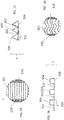
- FIGs. 2A and 2B respectively, the upper surface 102 and the lower surface 104 are shown in greater detail. Both surfaces includes axial fins that are better illustrated in the FIG. 3A which is an enlarged view of the region defined by circle B in FIG. 2A .
- the axial fins 301 may be any type of fins having including fins having a block cross-section ( FIG. 3B ), a triangular cross section ( FIG. 3C ) and may be straight in the axial direction as shown in FIG. 3A or wavy as shown in FIG. 3D .
- Each fin 301 includes a valley 302 and a peak 304 with the peaks 304 extending upwardly from a base layer 306.
- the base layer may be a separate layer or may just be defined by the valleys in FIG. 3B .
- the upper and lower layers are formed of ceramic.
- the layers as well as both the axial fins 301 and the transverse fins 110 are formed by an additive laminated object manufacturing process.
- thin ceramic tape layers form the base layer 306 and the transverse and axial fins 110, 301 are formed by layering additional tape layers (with holes typically formed therein) on top of the base layer 306.
- the tape layers can be formed from various materials, e.g., aluminum nitride, alumina, silicon nitride, etc. by tape casting process.
- the transverse fins 110 in one embodiment, have a height (h trans ) and width (w trans ) that is greater than the width (w peak ) or height (h peak ) of any peak of the axial fins 310 (see FIGs. 1 and 4 ).
- the top layer 102 is flipped over such that the upper surface of the transverse fins (which are perpendicular to the axial fins as illustrated) lie on the top of the axial fins of the lower layer 104.
- the transverse fins 110 provide structural support that allows the upper layer 102 to be stacked on top of the lower layer 104 without breakage.
- the distance (w) between the transverse fins 110 is the same on upper and lower layers 102, 104 in one embodiment. In both FIGs. 2A and 2B the flow direction is shown by arrow F.
- the transverse fins 110 lead to a serpentine flow path as shown by arrow A. That is, when the top layer 102 is joined the bottom layer, the fins are offset from one another. This flow path can be optimized for minimum flow pressure drop while ensuring benefits through thermal boundary layer break-up. This can be done by varying the height of the axial and transverse fins. Also shown are curved arrows that indicate the air/fluid is passing over the fins 110.
- a cross-section taken along section line 4-4 shows an upper layer 102 resting on and supported by a lower layer 104.
- the upper layer 102 includes a transverse fin 110 extending downwardly (e.g., in the opposite direction of direction X) from the base layer 306.
- the transverse fin 110 has a height h trans and sits on and makes contact with (in some cases direct contract) with the peak 304 of at least one of the axial fins 301.
- One or more of the axial fins 301 has a height h peak and at least one of the axial fins has a peak with a width w peak .
- the flow path A shown in FIG. 1 is traveling into the page in FIG. 4 .
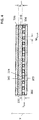
- FIG. 5 shows a simplified version of a heat exchanger 500.
- the exchanger 500 includes a first layer 502 and a second layer 504 disposed on top of the first layer 502.
- Each of the layers 502, 504 can be formed as described above.
- the first layer 502 allows air flow in first direction C and the second layer 504 allows air flow in a second direction D.
- first direction C and second direction D are perpendicular to one another.
- the transverse fins in the first and second layers 502, 504 may be perpendicular to one another and the axial fins in the first and second layers 502, 504 may also be perpendicular to one another.
- a complete heat exchanger can include several layers 502, 504 which can be individually formed by a LOM process and later joined (e.g., brazed) together to make a full size heat exchangers.
- multiple tape layer may be stacked.
- the tape layers consist of transverse fins which are offset in the axial direction in at least one tape layer so that the serpentine flow path is formed.
Landscapes
- Engineering & Computer Science (AREA)
- Mechanical Engineering (AREA)
- Physics & Mathematics (AREA)
- Thermal Sciences (AREA)
- General Engineering & Computer Science (AREA)
- Ceramic Engineering (AREA)
- Heat-Exchange Devices With Radiators And Conduit Assemblies (AREA)
Abstract
Description
- This invention was made with government support with DOE NETL under Contract No. DE-FE0024066 with a Sub Contract with support from Ceralink, Inc. under Contract No. PO-C-005. The government therefore has certain rights in this invention.
- The subject matter disclosed herein generally relates to heat exchangers, and more specifically, to wave fin structure for heat exchangers.
- A typical air-to-air plate fin heat exchanger consists of a stack of inter-conductive air flow sections or layers. Hot air and cold air are forced through alternate layers (referred to as "hot" and "cold" layers, respectively, from time to time herein) in order to exchange heat. In a gas turbine blade disk cooling system, the hot air comes from the engine compressor before entering the turbine blade disks and then flows through bleed layers. The cold air is outside air and flows through ram layers in the engine fan ducts. These alternately stacked ram and bleed layers are joined together along a thermally conductive medium called the parting sheet, and heat from the bleed layers is transmitted through the parting sheets to the ram air flow. Of course, heat exchangers could receive air from other sources as well and the teachings herein are not limited to gas turbine management.
- The hot and cold layers are similar and each includes an array of cooling fins and frames or closure bars which are positioned on the parting sheets to define each layer. Frames or closure bars are placed along the edges of the layers to support the ends of the parting sheets. In addition to supporting the ends of the parting sheets, theses bars close off each layer, except where there is an air inlet or an air outlet. At the air inlets and outlets the fins provide support for the parting sheets.
- To fabricate the heat exchanger, the hot and cold layers are stacked alternately one on top of another. The assembly may then be places in a vacuum furnace for brazing. During the brazing process the stack is squeezed so as to force the layers together.
- The above description relates to heat exchangers that may be made with what are called "low temperature" materials. High temperature heat exchanger may be required where bleed air operating temperatures that exceed the capability of conventional metals (e.g., low temperature). However, some aircraft or other situations may require compact heat exchangers include aircraft engine pre-coolers, gas power plant recuperators, and solid oxide fuel cell waste heat recovery, etc. that are in the high temperature range (T > 800 °C). Widely used materials which can withstand temperature up to 700 °C are metal superalloys, such as stainless steel, inconel, and Haynes. Ceramic heat exchanger technology provides a solution to the high temperature requirements and may allow for inlet temperatures up to 900 °C. However, ceramic heat exchanger development has been limited in past years due to poor thermal conductivity and high machining/manufacturing costs.
- In one aspect, a heat exchanger is disclosed. The heat exchanger includes a first additively manufactured layer including axial fins extending in a first direction and transverse fins extending in a second direction transverse to the first direction, the first layer defining a flow path in the first direction. The heat exchanger also includes a second additively manufactured layer including axial fins extending in the second and transverse fins extending in the first direction, the second layer defining a second flow path in the second direction.
- In another aspect, a layer of a heat exchanger is disclosed. The layer includes a top additively manufactured layer including axial fins extending in a first direction and transverse fins extending in a second direction transverse to the first direction and a bottom additively manufactured layer including axial fins extending in the first and transverse fins extending in the second direction. The transverse fins of the top additively manufactured layer contact a peak portion of the axial fins of the bottom additively manufactured layer.
- In another aspect, a method of forming a layer of a heat exchanger is disclosed. The method includes: additively manufacturing a top layer including axial fins extending in a first direction and transverse fins extending in a second direction transverse to the first direction; additively manufacturing a bottom layer including axial fins extending in the first and transverse fins extending in the second direction; and placing the top additively manufactured layer on the bottom additively manufactured layer such that the transverse fins of top additively manufactured layer contact a peak portion of the axial fins of the bottom additively manufactured layer.
- These and other advantages and features will become more apparent from the following description taken in conjunction with the drawings.
- The subject matter, which is regarded as the invention, is particularly pointed out and distinctly claimed in the claims at the conclusion of the specification. The foregoing and other features, and advantages of the invention are apparent from the following detailed description taken in conjunction with the accompanying drawings in which:
-
FIG. 1 is a partially cut-away perspective view of one layer of a heat exchanger according to one embodiment; -
FIGs. 2A and 2B show top and bottom layers, respectively, of the layer ofFIG. 1 ; -
FIGs. 3A-3D show various patterns and shapes of the fins in the layer ofFIG. 1 ; -
FIG. 4 shows a cross-section of the layer ofFIG. 1 ; and -
FIG. 5 shows a perspective view of heat exchanger according to one embodiment. - The detailed description explains embodiments of the invention, together with advantages and features, by way of example with reference to the drawings.
- Embodiments disclosed herein may enable the manufacture of a high temperature plate-fin (cross-flow) ceramic heat exchanger by a layer-by-layer additive manufacturing process. In one embodiment, the process is a so-called Laminated Object Manufacturing (LOM) process.
- In the vertical build direction of a plain fin prior art heat exchanger, the plain fin designs are non-manufacturable by the additive LOM process. This is due to difficulty in handling of the thin and long fin strips in each tape layer and subsequent stacking up of the fin layers. The thin and long heat transfer fins are difficult to pick up in the manufacturing process.
-
FIG. 1 shows a partial cross section of an example ofsingle layer 100 of a heat exchanger. Thelayer 100 includes anupper surface 102 and alower surface 104. These surfaces define a flow path, shown by arrow A. Each of the upper andlower surfaces - The flow path A is traversing
axial fins 301 that extend in the general direction of arrow A. Transverse to the general flow direction of arrow A, a plurality oftransverse fins 110. Thesetransverse fins 110 sit on top of the axial fins 310 and block air from passing from directly from theinlet 120 to theoutlet 122 of thelayer 100. This causes the flow to raise and lower over them leading to rising 124 and falling 126 segments of the flow path. Thetransverse fins 110 can be made more aerodynamic (e.g., sinusoidal in shape) so that the pressure drop caused by thetransverse fins 110 is minimal. They can also be placed in the fully developed flow region (if laminar) to disrupt the thermal boundary layer and improve heat transfer coefficient. Such a flow path may be referred to as a serpentine flow path from time to time herein. As shown, theinlet 120 includesseveral inlet holes 106. Theseholes 106 are examples only and can be any shape or can be omitted depending on the input header. - In
FIGs. 2A and 2B , respectively, theupper surface 102 and thelower surface 104 are shown in greater detail. Both surfaces includes axial fins that are better illustrated in theFIG. 3A which is an enlarged view of the region defined by circle B inFIG. 2A . Theaxial fins 301 may be any type of fins having including fins having a block cross-section (FIG. 3B ), a triangular cross section (FIG. 3C ) and may be straight in the axial direction as shown inFIG. 3A or wavy as shown inFIG. 3D . Eachfin 301 includes avalley 302 and a peak 304 with thepeaks 304 extending upwardly from abase layer 306. The base layer may be a separate layer or may just be defined by the valleys inFIG. 3B . - In embodiments herein, the upper and lower layers are formed of ceramic. The layers as well as both the
axial fins 301 and thetransverse fins 110 are formed by an additive laminated object manufacturing process. In particular, thin ceramic tape layers form thebase layer 306 and the transverse andaxial fins base layer 306. The tape layers can be formed from various materials, e.g., aluminum nitride, alumina, silicon nitride, etc. by tape casting process. - In the vertical build direction (shown by direction X in
FIGs. 3B and 3C ) of a prior art fin heat exchanger, it was not possible to form the axial fins by the additive laminated object manufacturing process in a manner that they are used to form a layer of a prior art heat exchanger. This is due to very difficult handling of the sheets including thin and long fins in each tape layer and subsequent stacking up of the layers as the thin and long heat transfer fins are difficult to pick up in the manufacturing process. - This problem is reduced or removed by adding the
transverse fins 110. Thetransverse fins 110, in one embodiment, have a height (htrans) and width (wtrans) that is greater than the width (wpeak) or height (hpeak) of any peak of the axial fins 310 (seeFIGs. 1 and4 ). - Referring again to
FIGs. 2A and 2B , thetop layer 102 is flipped over such that the upper surface of the transverse fins (which are perpendicular to the axial fins as illustrated) lie on the top of the axial fins of thelower layer 104. Thetransverse fins 110 provide structural support that allows theupper layer 102 to be stacked on top of thelower layer 104 without breakage. The distance (w) between thetransverse fins 110 is the same on upper andlower layers FIGs. 2A and 2B the flow direction is shown by arrow F. - As discussed above, the
transverse fins 110 lead to a serpentine flow path as shown by arrow A. That is, when thetop layer 102 is joined the bottom layer, the fins are offset from one another. This flow path can be optimized for minimum flow pressure drop while ensuring benefits through thermal boundary layer break-up. This can be done by varying the height of the axial and transverse fins. Also shown are curved arrows that indicate the air/fluid is passing over thefins 110. - Referring now to
FIG. 4 , a cross-section taken along section line 4-4 shows anupper layer 102 resting on and supported by alower layer 104. Theupper layer 102 includes atransverse fin 110 extending downwardly (e.g., in the opposite direction of direction X) from thebase layer 306. Thetransverse fin 110 has a height htrans and sits on and makes contact with (in some cases direct contract) with thepeak 304 of at least one of theaxial fins 301. One or more of theaxial fins 301 has a height hpeak and at least one of the axial fins has a peak with a width wpeak. As shown the flow path A shown inFIG. 1 is traveling into the page inFIG. 4 . -
FIG. 5 shows a simplified version of aheat exchanger 500. Theexchanger 500 includes afirst layer 502 and asecond layer 504 disposed on top of thefirst layer 502. Each of thelayers first layer 502 allows air flow in first direction C and thesecond layer 504 allows air flow in a second direction D. In one embodiment, first direction C and second direction D are perpendicular to one another. As such, the transverse fins in the first andsecond layers second layers several layers - In a given flow path layer (i.e., combination of a stack tape layers with axial and transverse fins), multiple tape layer may be stacked. The tape layers consist of transverse fins which are offset in the axial direction in at least one tape layer so that the serpentine flow path is formed.
- While the invention has been described in detail in connection with only a limited number of embodiments, it should be readily understood that the invention is not limited to such disclosed embodiments. Rather, the invention can be modified to incorporate any number of variations, alterations, substitutions or equivalent arrangements not heretofore described, but which are commensurate with the spirit and scope of the invention. Additionally, while various embodiments of the invention have been described, it is to be understood that aspects of the invention may include only some of the described embodiments. Accordingly, the invention is not to be seen as limited by the foregoing description, but is only limited by the scope of the appended claims.
Claims (9)
- A heat exchanger (500) comprising:a first additively manufactured layer (502) including axial fins extending in a first direction and transverse fins extending in a second direction transverse to the first direction, the first layer defining a flow path in the first direction; anda second additively manufactured layer (504) including axial fins extending in the second and transverse fins extending in the first direction, the second layer defining a second flow path in the second direction.
- The heat exchanger of claim 1, wherein the first additively manufactured layer (502) is formed by a Laminated Object Manufacturing (LOM) process.
- The heat exchanger of claim 1, wherein, in the first additively manufactured layer (502), the axial fins include a peak and a valley and the height of the peak is less than a height of the transverse fins.
- The heat exchanger of claim 3, wherein a width of the peaks is less than a width of the transverse fins.
- The heat exchanger of claim 1, wherein the first and second directions are perpendicular to one another.
- The heat exchanger of claim 1, wherein the first and second additively manufactured layers (502, 504) are formed of a ceramic material.
- A method of forming a layer of a heat exchanger comprising:additively manufacturing a top layer including axial fins extending in a first direction and transverse fins extending in a second direction transverse to the first direction;additively manufacturing a bottom layer including axial fins extending in the first and transverse fins extending in the second direction; andplacing the top additively manufactured layer on the bottom additively manufactured layer such that the transverse fins of top additively manufactured layer contact a peak portion of the axial fins of the bottom additively manufactured layer.
- The method of claim 7, wherein the top and bottom additively manufactured layers are formed by a Laminated Object Manufacturing (LOM) process.
- The method of claim 7, wherein the first and second additively manufactured layers are formed of a ceramic material.
Applications Claiming Priority (1)
| Application Number | Priority Date | Filing Date | Title |
|---|---|---|---|
| US14/956,439 US10646969B2 (en) | 2015-12-02 | 2015-12-02 | Cross flow ceramic heat exchanger and method for manufacturing |
Publications (2)
| Publication Number | Publication Date |
|---|---|
| EP3176533A1 true EP3176533A1 (en) | 2017-06-07 |
| EP3176533B1 EP3176533B1 (en) | 2018-08-15 |
Family
ID=57189751
Family Applications (1)
| Application Number | Title | Priority Date | Filing Date |
|---|---|---|---|
| EP16191941.0A Active EP3176533B1 (en) | 2015-12-02 | 2016-09-30 | Cross flow ceramic heat exchanger and method for manufacturing |
Country Status (3)
| Country | Link |
|---|---|
| US (1) | US10646969B2 (en) |
| EP (1) | EP3176533B1 (en) |
| JP (1) | JP6842873B2 (en) |
Cited By (1)
| Publication number | Priority date | Publication date | Assignee | Title |
|---|---|---|---|---|
| GB2556653A (en) * | 2016-09-12 | 2018-06-06 | Hamilton Sundstrand Corp | Method of manufacturing a heat exchanger |
Families Citing this family (4)
| Publication number | Priority date | Publication date | Assignee | Title |
|---|---|---|---|---|
| DE102018003479A1 (en) * | 2018-04-27 | 2019-10-31 | Linde Aktiengesellschaft | Plate heat exchanger, process plant and process |
| US11306979B2 (en) * | 2018-12-05 | 2022-04-19 | Hamilton Sundstrand Corporation | Heat exchanger riblet and turbulator features for improved manufacturability and performance |
| US11045912B2 (en) * | 2019-06-18 | 2021-06-29 | Hamilton Sundstrand Corporation | Method of fabricating an oscillating heat pipe |
| JP7358152B2 (en) | 2019-09-24 | 2023-10-10 | 住友精密工業株式会社 | Heat exchanger |
Citations (3)
| Publication number | Priority date | Publication date | Assignee | Title |
|---|---|---|---|---|
| US4362209A (en) * | 1978-09-01 | 1982-12-07 | Gte Products Corporation | Ceramic heat recuperative structure and assembly |
| US4379109A (en) * | 1978-02-02 | 1983-04-05 | W. R. Grace & Co. | Method of preparing a monolithic structure having flow channels |
| WO1998037457A1 (en) * | 1997-02-20 | 1998-08-27 | Atotech Deutschland Gmbh | Chemical microreactors and method for producing same |
Family Cites Families (17)
| Publication number | Priority date | Publication date | Assignee | Title |
|---|---|---|---|---|
| US1662870A (en) * | 1924-10-09 | 1928-03-20 | Stancliffe Engineering Corp | Grooved-plate heat interchanger |
| US4083400A (en) * | 1976-05-13 | 1978-04-11 | Gte Sylvania, Incorporated | Heat recuperative apparatus incorporating a cellular ceramic core |
| US4270602A (en) * | 1978-08-30 | 1981-06-02 | The Garrett Corporation | Heat exchanger |
| JPS56146997A (en) * | 1980-04-16 | 1981-11-14 | Noritake Co Ltd | Heat transfer body in ceramic and its manufacture, and heat exchanger using said heat transfer body |
| JPH0619982Y2 (en) * | 1985-11-29 | 1994-05-25 | 株式会社東芝 | Counterflow heat exchanger |
| JPH07234087A (en) * | 1994-02-24 | 1995-09-05 | Daikin Ind Ltd | Heat exchange element |
| US5626188A (en) * | 1995-04-13 | 1997-05-06 | Alliedsignal Inc. | Composite machined fin heat exchanger |
| US6730998B1 (en) | 2000-02-10 | 2004-05-04 | Micron Technology, Inc. | Stereolithographic method for fabricating heat sinks, stereolithographically fabricated heat sinks, and semiconductor devices including same |
| US7871578B2 (en) | 2005-05-02 | 2011-01-18 | United Technologies Corporation | Micro heat exchanger with thermally conductive porous network |
| DE102006022598B4 (en) | 2005-10-12 | 2018-05-30 | Papiertechnische Stiftung München | Process for producing a ceramic from pre-ceramic paper or cardboard structures |
| US8726976B2 (en) | 2008-02-22 | 2014-05-20 | Liebert Corporation | Laminated sheet manifold for microchannel heat exchanger |
| JP6335782B2 (en) * | 2011-07-13 | 2018-05-30 | ヌボトロニクス、インク. | Method for fabricating electronic and mechanical structures |
| DE102011080782B4 (en) * | 2011-08-10 | 2014-09-04 | Eberspächer Exhaust Technology GmbH & Co. KG | Latent heat storage and catalyst |
| EP2639541B1 (en) * | 2012-03-14 | 2017-04-26 | Alfa Laval Corporate AB | Flow-plate for heat transfer |
| PL401970A1 (en) * | 2012-12-10 | 2014-06-23 | Synertec Spółka Z Ograniczoną Opdowiedzialnością | Thin-walled plate heat exchanger |
| EP3071913B1 (en) * | 2013-11-18 | 2020-06-03 | General Electric Company | Monolithic tube-in matrix heat exchanger |
| US20150137412A1 (en) | 2013-11-20 | 2015-05-21 | Carl Schalansky | Method of using additive materials for production of fluid flow channels |
-
2015
- 2015-12-02 US US14/956,439 patent/US10646969B2/en active Active
-
2016
- 2016-09-30 JP JP2016193280A patent/JP6842873B2/en active Active
- 2016-09-30 EP EP16191941.0A patent/EP3176533B1/en active Active
Patent Citations (3)
| Publication number | Priority date | Publication date | Assignee | Title |
|---|---|---|---|---|
| US4379109A (en) * | 1978-02-02 | 1983-04-05 | W. R. Grace & Co. | Method of preparing a monolithic structure having flow channels |
| US4362209A (en) * | 1978-09-01 | 1982-12-07 | Gte Products Corporation | Ceramic heat recuperative structure and assembly |
| WO1998037457A1 (en) * | 1997-02-20 | 1998-08-27 | Atotech Deutschland Gmbh | Chemical microreactors and method for producing same |
Cited By (1)
| Publication number | Priority date | Publication date | Assignee | Title |
|---|---|---|---|---|
| GB2556653A (en) * | 2016-09-12 | 2018-06-06 | Hamilton Sundstrand Corp | Method of manufacturing a heat exchanger |
Also Published As
| Publication number | Publication date |
|---|---|
| JP2017101914A (en) | 2017-06-08 |
| JP6842873B2 (en) | 2021-03-17 |
| EP3176533B1 (en) | 2018-08-15 |
| US10646969B2 (en) | 2020-05-12 |
| US20170157722A1 (en) | 2017-06-08 |
Similar Documents
| Publication | Publication Date | Title |
|---|---|---|
| US10415901B2 (en) | Counter-flow ceramic heat exchanger assembly and method | |
| EP3176533B1 (en) | Cross flow ceramic heat exchanger and method for manufacturing | |
| US20260126249A1 (en) | Heat augmentation features in a cast heat exchanger | |
| US9851159B2 (en) | Curved cross-flow heat exchanger | |
| US20200080796A1 (en) | Additive manufactured heat exchanger | |
| US9638471B2 (en) | Balanced heat exchanger systems and methods | |
| EP3106817A1 (en) | Plate fin heat exchanger | |
| EP3553446B1 (en) | Shaped leading edge of cast plate fin heat exchanger | |
| EP2853851B1 (en) | Heat exchanger thermal fatigue stress reduction | |
| JP5511917B2 (en) | Assembly structure of plate fin type heat exchanger and manufacturing method of plate fin type heat exchanger | |
| US12013194B2 (en) | Asymmetric cross counter flow heat exchanger | |
| EP2977703B1 (en) | Heat exchanger with slotted guard fin | |
| US20230175785A1 (en) | Flat plate heat exchanger | |
| US11187470B2 (en) | Plate fin crossflow heat exchanger | |
| EP3043138B1 (en) | Heat exchanger with fin wave control | |
| EP3553448B1 (en) | Secondarily applied cold side features for cast heat exchanger | |
| EP4498030A1 (en) | Heat exchanger | |
| JPH07167580A (en) | Operating method of plate fin type heat exchanger | |
| JP2009222306A (en) | Unit core for plate fin type heat exchanger, assembly structure of heat exchanger using the unit core and method for manufacturing heat exchanger | |
| US12578147B2 (en) | Varied flow stacked radiators | |
| CN211346458U (en) | Plate-fin heat exchanger core | |
| JPH0729413Y2 (en) | Plate fin type heat exchanger |
Legal Events
| Date | Code | Title | Description |
|---|---|---|---|
| AK | Designated contracting states |
Kind code of ref document: A1 Designated state(s): AL AT BE BG CH CY CZ DE DK EE ES FI FR GB GR HR HU IE IS IT LI LT LU LV MC MK MT NL NO PL PT RO RS SE SI SK SM TR |
|
| AX | Request for extension of the european patent |
Extension state: BA ME |
|
| PUAI | Public reference made under article 153(3) epc to a published international application that has entered the european phase |
Free format text: ORIGINAL CODE: 0009012 |
|
| STAA | Information on the status of an ep patent application or granted ep patent |
Free format text: STATUS: THE APPLICATION HAS BEEN PUBLISHED |
|
| STAA | Information on the status of an ep patent application or granted ep patent |
Free format text: STATUS: REQUEST FOR EXAMINATION WAS MADE |
|
| 17P | Request for examination filed |
Effective date: 20171207 |
|
| RBV | Designated contracting states (corrected) |
Designated state(s): AL AT BE BG CH CY CZ DE DK EE ES FI FR GB GR HR HU IE IS IT LI LT LU LV MC MK MT NL NO PL PT RO RS SE SI SK SM TR |
|
| GRAP | Despatch of communication of intention to grant a patent |
Free format text: ORIGINAL CODE: EPIDOSNIGR1 |
|
| STAA | Information on the status of an ep patent application or granted ep patent |
Free format text: STATUS: GRANT OF PATENT IS INTENDED |
|
| INTG | Intention to grant announced |
Effective date: 20180220 |
|
| GRAS | Grant fee paid |
Free format text: ORIGINAL CODE: EPIDOSNIGR3 |
|
| GRAA | (expected) grant |
Free format text: ORIGINAL CODE: 0009210 |
|
| STAA | Information on the status of an ep patent application or granted ep patent |
Free format text: STATUS: THE PATENT HAS BEEN GRANTED |
|
| AK | Designated contracting states |
Kind code of ref document: B1 Designated state(s): AL AT BE BG CH CY CZ DE DK EE ES FI FR GB GR HR HU IE IS IT LI LT LU LV MC MK MT NL NO PL PT RO RS SE SI SK SM TR |
|
| REG | Reference to a national code |
Ref country code: CH Ref legal event code: EP Ref country code: GB Ref legal event code: FG4D Ref country code: AT Ref legal event code: REF Ref document number: 1030282 Country of ref document: AT Kind code of ref document: T Effective date: 20180815 |
|
| REG | Reference to a national code |
Ref country code: IE Ref legal event code: FG4D |
|
| REG | Reference to a national code |
Ref country code: DE Ref legal event code: R096 Ref document number: 602016004764 Country of ref document: DE |
|
| REG | Reference to a national code |
Ref country code: FR Ref legal event code: PLFP Year of fee payment: 3 |
|
| REG | Reference to a national code |
Ref country code: NL Ref legal event code: MP Effective date: 20180815 |
|
| REG | Reference to a national code |
Ref country code: LT Ref legal event code: MG4D |
|
| REG | Reference to a national code |
Ref country code: AT Ref legal event code: MK05 Ref document number: 1030282 Country of ref document: AT Kind code of ref document: T Effective date: 20180815 |
|
| PG25 | Lapsed in a contracting state [announced via postgrant information from national office to epo] |
Ref country code: BG Free format text: LAPSE BECAUSE OF FAILURE TO SUBMIT A TRANSLATION OF THE DESCRIPTION OR TO PAY THE FEE WITHIN THE PRESCRIBED TIME-LIMIT Effective date: 20181115 Ref country code: SE Free format text: LAPSE BECAUSE OF FAILURE TO SUBMIT A TRANSLATION OF THE DESCRIPTION OR TO PAY THE FEE WITHIN THE PRESCRIBED TIME-LIMIT Effective date: 20180815 Ref country code: GR Free format text: LAPSE BECAUSE OF FAILURE TO SUBMIT A TRANSLATION OF THE DESCRIPTION OR TO PAY THE FEE WITHIN THE PRESCRIBED TIME-LIMIT Effective date: 20181116 Ref country code: NO Free format text: LAPSE BECAUSE OF FAILURE TO SUBMIT A TRANSLATION OF THE DESCRIPTION OR TO PAY THE FEE WITHIN THE PRESCRIBED TIME-LIMIT Effective date: 20181115 Ref country code: AT Free format text: LAPSE BECAUSE OF FAILURE TO SUBMIT A TRANSLATION OF THE DESCRIPTION OR TO PAY THE FEE WITHIN THE PRESCRIBED TIME-LIMIT Effective date: 20180815 Ref country code: IS Free format text: LAPSE BECAUSE OF FAILURE TO SUBMIT A TRANSLATION OF THE DESCRIPTION OR TO PAY THE FEE WITHIN THE PRESCRIBED TIME-LIMIT Effective date: 20181215 Ref country code: RS Free format text: LAPSE BECAUSE OF FAILURE TO SUBMIT A TRANSLATION OF THE DESCRIPTION OR TO PAY THE FEE WITHIN THE PRESCRIBED TIME-LIMIT Effective date: 20180815 Ref country code: FI Free format text: LAPSE BECAUSE OF FAILURE TO SUBMIT A TRANSLATION OF THE DESCRIPTION OR TO PAY THE FEE WITHIN THE PRESCRIBED TIME-LIMIT Effective date: 20180815 Ref country code: LT Free format text: LAPSE BECAUSE OF FAILURE TO SUBMIT A TRANSLATION OF THE DESCRIPTION OR TO PAY THE FEE WITHIN THE PRESCRIBED TIME-LIMIT Effective date: 20180815 Ref country code: NL Free format text: LAPSE BECAUSE OF FAILURE TO SUBMIT A TRANSLATION OF THE DESCRIPTION OR TO PAY THE FEE WITHIN THE PRESCRIBED TIME-LIMIT Effective date: 20180815 |
|
| PG25 | Lapsed in a contracting state [announced via postgrant information from national office to epo] |
Ref country code: LV Free format text: LAPSE BECAUSE OF FAILURE TO SUBMIT A TRANSLATION OF THE DESCRIPTION OR TO PAY THE FEE WITHIN THE PRESCRIBED TIME-LIMIT Effective date: 20180815 Ref country code: AL Free format text: LAPSE BECAUSE OF FAILURE TO SUBMIT A TRANSLATION OF THE DESCRIPTION OR TO PAY THE FEE WITHIN THE PRESCRIBED TIME-LIMIT Effective date: 20180815 Ref country code: HR Free format text: LAPSE BECAUSE OF FAILURE TO SUBMIT A TRANSLATION OF THE DESCRIPTION OR TO PAY THE FEE WITHIN THE PRESCRIBED TIME-LIMIT Effective date: 20180815 |
|
| REG | Reference to a national code |
Ref country code: DE Ref legal event code: R119 Ref document number: 602016004764 Country of ref document: DE |
|
| PG25 | Lapsed in a contracting state [announced via postgrant information from national office to epo] |
Ref country code: IT Free format text: LAPSE BECAUSE OF FAILURE TO SUBMIT A TRANSLATION OF THE DESCRIPTION OR TO PAY THE FEE WITHIN THE PRESCRIBED TIME-LIMIT Effective date: 20180815 Ref country code: EE Free format text: LAPSE BECAUSE OF FAILURE TO SUBMIT A TRANSLATION OF THE DESCRIPTION OR TO PAY THE FEE WITHIN THE PRESCRIBED TIME-LIMIT Effective date: 20180815 Ref country code: CZ Free format text: LAPSE BECAUSE OF FAILURE TO SUBMIT A TRANSLATION OF THE DESCRIPTION OR TO PAY THE FEE WITHIN THE PRESCRIBED TIME-LIMIT Effective date: 20180815 Ref country code: PL Free format text: LAPSE BECAUSE OF FAILURE TO SUBMIT A TRANSLATION OF THE DESCRIPTION OR TO PAY THE FEE WITHIN THE PRESCRIBED TIME-LIMIT Effective date: 20180815 Ref country code: RO Free format text: LAPSE BECAUSE OF FAILURE TO SUBMIT A TRANSLATION OF THE DESCRIPTION OR TO PAY THE FEE WITHIN THE PRESCRIBED TIME-LIMIT Effective date: 20180815 Ref country code: ES Free format text: LAPSE BECAUSE OF FAILURE TO SUBMIT A TRANSLATION OF THE DESCRIPTION OR TO PAY THE FEE WITHIN THE PRESCRIBED TIME-LIMIT Effective date: 20180815 |
|
| PG25 | Lapsed in a contracting state [announced via postgrant information from national office to epo] |
Ref country code: SK Free format text: LAPSE BECAUSE OF FAILURE TO SUBMIT A TRANSLATION OF THE DESCRIPTION OR TO PAY THE FEE WITHIN THE PRESCRIBED TIME-LIMIT Effective date: 20180815 Ref country code: DK Free format text: LAPSE BECAUSE OF FAILURE TO SUBMIT A TRANSLATION OF THE DESCRIPTION OR TO PAY THE FEE WITHIN THE PRESCRIBED TIME-LIMIT Effective date: 20180815 Ref country code: SM Free format text: LAPSE BECAUSE OF FAILURE TO SUBMIT A TRANSLATION OF THE DESCRIPTION OR TO PAY THE FEE WITHIN THE PRESCRIBED TIME-LIMIT Effective date: 20180815 |
|
| REG | Reference to a national code |
Ref country code: BE Ref legal event code: MM Effective date: 20180930 |
|
| PLBE | No opposition filed within time limit |
Free format text: ORIGINAL CODE: 0009261 |
|
| STAA | Information on the status of an ep patent application or granted ep patent |
Free format text: STATUS: NO OPPOSITION FILED WITHIN TIME LIMIT |
|
| REG | Reference to a national code |
Ref country code: IE Ref legal event code: MM4A |
|
| PG25 | Lapsed in a contracting state [announced via postgrant information from national office to epo] |
Ref country code: LU Free format text: LAPSE BECAUSE OF NON-PAYMENT OF DUE FEES Effective date: 20180930 Ref country code: MC Free format text: LAPSE BECAUSE OF FAILURE TO SUBMIT A TRANSLATION OF THE DESCRIPTION OR TO PAY THE FEE WITHIN THE PRESCRIBED TIME-LIMIT Effective date: 20180815 |
|
| 26N | No opposition filed |
Effective date: 20190516 |
|
| PG25 | Lapsed in a contracting state [announced via postgrant information from national office to epo] |
Ref country code: DE Free format text: LAPSE BECAUSE OF NON-PAYMENT OF DUE FEES Effective date: 20190402 Ref country code: IE Free format text: LAPSE BECAUSE OF NON-PAYMENT OF DUE FEES Effective date: 20180930 |
|
| PG25 | Lapsed in a contracting state [announced via postgrant information from national office to epo] |
Ref country code: BE Free format text: LAPSE BECAUSE OF NON-PAYMENT OF DUE FEES Effective date: 20180930 Ref country code: SI Free format text: LAPSE BECAUSE OF FAILURE TO SUBMIT A TRANSLATION OF THE DESCRIPTION OR TO PAY THE FEE WITHIN THE PRESCRIBED TIME-LIMIT Effective date: 20180815 |
|
| PG25 | Lapsed in a contracting state [announced via postgrant information from national office to epo] |
Ref country code: MT Free format text: LAPSE BECAUSE OF NON-PAYMENT OF DUE FEES Effective date: 20180930 |
|
| PG25 | Lapsed in a contracting state [announced via postgrant information from national office to epo] |
Ref country code: TR Free format text: LAPSE BECAUSE OF FAILURE TO SUBMIT A TRANSLATION OF THE DESCRIPTION OR TO PAY THE FEE WITHIN THE PRESCRIBED TIME-LIMIT Effective date: 20180815 |
|
| PG25 | Lapsed in a contracting state [announced via postgrant information from national office to epo] |
Ref country code: PT Free format text: LAPSE BECAUSE OF FAILURE TO SUBMIT A TRANSLATION OF THE DESCRIPTION OR TO PAY THE FEE WITHIN THE PRESCRIBED TIME-LIMIT Effective date: 20180815 |
|
| REG | Reference to a national code |
Ref country code: CH Ref legal event code: PL |
|
| PG25 | Lapsed in a contracting state [announced via postgrant information from national office to epo] |
Ref country code: CY Free format text: LAPSE BECAUSE OF FAILURE TO SUBMIT A TRANSLATION OF THE DESCRIPTION OR TO PAY THE FEE WITHIN THE PRESCRIBED TIME-LIMIT Effective date: 20180815 Ref country code: MK Free format text: LAPSE BECAUSE OF NON-PAYMENT OF DUE FEES Effective date: 20180815 Ref country code: HU Free format text: LAPSE BECAUSE OF FAILURE TO SUBMIT A TRANSLATION OF THE DESCRIPTION OR TO PAY THE FEE WITHIN THE PRESCRIBED TIME-LIMIT; INVALID AB INITIO Effective date: 20160930 |
|
| PG25 | Lapsed in a contracting state [announced via postgrant information from national office to epo] |
Ref country code: CH Free format text: LAPSE BECAUSE OF NON-PAYMENT OF DUE FEES Effective date: 20190930 Ref country code: LI Free format text: LAPSE BECAUSE OF NON-PAYMENT OF DUE FEES Effective date: 20190930 |
|
| P01 | Opt-out of the competence of the unified patent court (upc) registered |
Effective date: 20230522 |
|
| PGFP | Annual fee paid to national office [announced via postgrant information from national office to epo] |
Ref country code: GB Payment date: 20250820 Year of fee payment: 10 |
|
| PGFP | Annual fee paid to national office [announced via postgrant information from national office to epo] |
Ref country code: FR Payment date: 20250820 Year of fee payment: 10 |