JP7358152B2 - Heat exchanger - Google Patents
Heat exchanger Download PDFInfo
- Publication number
- JP7358152B2 JP7358152B2 JP2019172439A JP2019172439A JP7358152B2 JP 7358152 B2 JP7358152 B2 JP 7358152B2 JP 2019172439 A JP2019172439 A JP 2019172439A JP 2019172439 A JP2019172439 A JP 2019172439A JP 7358152 B2 JP7358152 B2 JP 7358152B2
- Authority
- JP
- Japan
- Prior art keywords
- flow path
- channel
- heat exchanger
- layer
- flow
- Prior art date
- Legal status (The legal status is an assumption and is not a legal conclusion. Google has not performed a legal analysis and makes no representation as to the accuracy of the status listed.)
- Active
Links
- 238000005192 partition Methods 0.000 claims description 55
- 239000012530 fluid Substances 0.000 claims description 52
- 230000015572 biosynthetic process Effects 0.000 claims description 24
- 230000007423 decrease Effects 0.000 claims description 7
- 239000010410 layer Substances 0.000 description 174
- 230000008859 change Effects 0.000 description 20
- 238000004519 manufacturing process Methods 0.000 description 8
- 239000000654 additive Substances 0.000 description 7
- 230000000996 additive effect Effects 0.000 description 7
- 238000010586 diagram Methods 0.000 description 7
- 238000000034 method Methods 0.000 description 6
- 230000000694 effects Effects 0.000 description 4
- 230000004048 modification Effects 0.000 description 4
- 238000012986 modification Methods 0.000 description 4
- 239000000843 powder Substances 0.000 description 4
- 238000005452 bending Methods 0.000 description 3
- 239000011159 matrix material Substances 0.000 description 3
- 230000008569 process Effects 0.000 description 3
- XEEYBQQBJWHFJM-UHFFFAOYSA-N Iron Chemical compound [Fe] XEEYBQQBJWHFJM-UHFFFAOYSA-N 0.000 description 2
- 229910052782 aluminium Inorganic materials 0.000 description 2
- XAGFODPZIPBFFR-UHFFFAOYSA-N aluminium Chemical compound [Al] XAGFODPZIPBFFR-UHFFFAOYSA-N 0.000 description 2
- 230000000052 comparative effect Effects 0.000 description 2
- 230000003247 decreasing effect Effects 0.000 description 2
- 239000000463 material Substances 0.000 description 2
- 230000009467 reduction Effects 0.000 description 2
- 229910000838 Al alloy Inorganic materials 0.000 description 1
- RYGMFSIKBFXOCR-UHFFFAOYSA-N Copper Chemical compound [Cu] RYGMFSIKBFXOCR-UHFFFAOYSA-N 0.000 description 1
- RTAQQCXQSZGOHL-UHFFFAOYSA-N Titanium Chemical compound [Ti] RTAQQCXQSZGOHL-UHFFFAOYSA-N 0.000 description 1
- 230000015556 catabolic process Effects 0.000 description 1
- 230000008602 contraction Effects 0.000 description 1
- 229910052802 copper Inorganic materials 0.000 description 1
- 239000010949 copper Substances 0.000 description 1
- 238000006073 displacement reaction Methods 0.000 description 1
- 238000010894 electron beam technology Methods 0.000 description 1
- 229910052742 iron Inorganic materials 0.000 description 1
- 239000007769 metal material Substances 0.000 description 1
- 230000000737 periodic effect Effects 0.000 description 1
- 230000000630 rising effect Effects 0.000 description 1
- 239000002356 single layer Substances 0.000 description 1
- 239000007787 solid Substances 0.000 description 1
- 239000010936 titanium Substances 0.000 description 1
- 229910052719 titanium Inorganic materials 0.000 description 1
Images


Classifications
-
- F—MECHANICAL ENGINEERING; LIGHTING; HEATING; WEAPONS; BLASTING
- F28—HEAT EXCHANGE IN GENERAL
- F28F—DETAILS OF HEAT-EXCHANGE AND HEAT-TRANSFER APPARATUS, OF GENERAL APPLICATION
- F28F3/00—Plate-like or laminated elements; Assemblies of plate-like or laminated elements
- F28F3/08—Elements constructed for building-up into stacks, e.g. capable of being taken apart for cleaning
-
- F—MECHANICAL ENGINEERING; LIGHTING; HEATING; WEAPONS; BLASTING
- F28—HEAT EXCHANGE IN GENERAL
- F28F—DETAILS OF HEAT-EXCHANGE AND HEAT-TRANSFER APPARATUS, OF GENERAL APPLICATION
- F28F7/00—Elements not covered by group F28F1/00, F28F3/00 or F28F5/00
- F28F7/02—Blocks traversed by passages for heat-exchange media
-
- B—PERFORMING OPERATIONS; TRANSPORTING
- B22—CASTING; POWDER METALLURGY
- B22F—WORKING METALLIC POWDER; MANUFACTURE OF ARTICLES FROM METALLIC POWDER; MAKING METALLIC POWDER; APPARATUS OR DEVICES SPECIALLY ADAPTED FOR METALLIC POWDER
- B22F5/00—Manufacture of workpieces or articles from metallic powder characterised by the special shape of the product
- B22F5/10—Manufacture of workpieces or articles from metallic powder characterised by the special shape of the product of articles with cavities or holes, not otherwise provided for in the preceding subgroups
-
- B—PERFORMING OPERATIONS; TRANSPORTING
- B33—ADDITIVE MANUFACTURING TECHNOLOGY
- B33Y—ADDITIVE MANUFACTURING, i.e. MANUFACTURING OF THREE-DIMENSIONAL [3-D] OBJECTS BY ADDITIVE DEPOSITION, ADDITIVE AGGLOMERATION OR ADDITIVE LAYERING, e.g. BY 3-D PRINTING, STEREOLITHOGRAPHY OR SELECTIVE LASER SINTERING
- B33Y80/00—Products made by additive manufacturing
-
- F—MECHANICAL ENGINEERING; LIGHTING; HEATING; WEAPONS; BLASTING
- F28—HEAT EXCHANGE IN GENERAL
- F28D—HEAT-EXCHANGE APPARATUS, NOT PROVIDED FOR IN ANOTHER SUBCLASS, IN WHICH THE HEAT-EXCHANGE MEDIA DO NOT COME INTO DIRECT CONTACT
- F28D7/00—Heat-exchange apparatus having stationary tubular conduit assemblies for both heat-exchange media, the media being in contact with different sides of a conduit wall
- F28D7/0008—Heat-exchange apparatus having stationary tubular conduit assemblies for both heat-exchange media, the media being in contact with different sides of a conduit wall the conduits for one medium being in heat conductive contact with the conduits for the other medium
-
- F—MECHANICAL ENGINEERING; LIGHTING; HEATING; WEAPONS; BLASTING
- F28—HEAT EXCHANGE IN GENERAL
- F28F—DETAILS OF HEAT-EXCHANGE AND HEAT-TRANSFER APPARATUS, OF GENERAL APPLICATION
- F28F1/00—Tubular elements; Assemblies of tubular elements
- F28F1/006—Tubular elements; Assemblies of tubular elements with variable shape, e.g. with modified tube ends, with different geometrical features
-
- F—MECHANICAL ENGINEERING; LIGHTING; HEATING; WEAPONS; BLASTING
- F28—HEAT EXCHANGE IN GENERAL
- F28F—DETAILS OF HEAT-EXCHANGE AND HEAT-TRANSFER APPARATUS, OF GENERAL APPLICATION
- F28F13/00—Arrangements for modifying heat-transfer, e.g. increasing, decreasing
- F28F13/06—Arrangements for modifying heat-transfer, e.g. increasing, decreasing by affecting the pattern of flow of the heat-exchange media
- F28F13/08—Arrangements for modifying heat-transfer, e.g. increasing, decreasing by affecting the pattern of flow of the heat-exchange media by varying the cross-section of the flow channels
-
- F—MECHANICAL ENGINEERING; LIGHTING; HEATING; WEAPONS; BLASTING
- F28—HEAT EXCHANGE IN GENERAL
- F28F—DETAILS OF HEAT-EXCHANGE AND HEAT-TRANSFER APPARATUS, OF GENERAL APPLICATION
- F28F13/00—Arrangements for modifying heat-transfer, e.g. increasing, decreasing
- F28F13/06—Arrangements for modifying heat-transfer, e.g. increasing, decreasing by affecting the pattern of flow of the heat-exchange media
- F28F13/12—Arrangements for modifying heat-transfer, e.g. increasing, decreasing by affecting the pattern of flow of the heat-exchange media by creating turbulence, e.g. by stirring, by increasing the force of circulation
-
- B—PERFORMING OPERATIONS; TRANSPORTING
- B22—CASTING; POWDER METALLURGY
- B22F—WORKING METALLIC POWDER; MANUFACTURE OF ARTICLES FROM METALLIC POWDER; MAKING METALLIC POWDER; APPARATUS OR DEVICES SPECIALLY ADAPTED FOR METALLIC POWDER
- B22F10/00—Additive manufacturing of workpieces or articles from metallic powder
- B22F10/20—Direct sintering or melting
- B22F10/28—Powder bed fusion, e.g. selective laser melting [SLM] or electron beam melting [EBM]
-
- B—PERFORMING OPERATIONS; TRANSPORTING
- B33—ADDITIVE MANUFACTURING TECHNOLOGY
- B33Y—ADDITIVE MANUFACTURING, i.e. MANUFACTURING OF THREE-DIMENSIONAL [3-D] OBJECTS BY ADDITIVE DEPOSITION, ADDITIVE AGGLOMERATION OR ADDITIVE LAYERING, e.g. BY 3-D PRINTING, STEREOLITHOGRAPHY OR SELECTIVE LASER SINTERING
- B33Y10/00—Processes of additive manufacturing
-
- F—MECHANICAL ENGINEERING; LIGHTING; HEATING; WEAPONS; BLASTING
- F28—HEAT EXCHANGE IN GENERAL
- F28F—DETAILS OF HEAT-EXCHANGE AND HEAT-TRANSFER APPARATUS, OF GENERAL APPLICATION
- F28F2250/00—Arrangements for modifying the flow of the heat exchange media, e.g. flow guiding means; Particular flow patterns
- F28F2250/10—Particular pattern of flow of the heat exchange media
- F28F2250/106—Particular pattern of flow of the heat exchange media with cross flow
-
- Y—GENERAL TAGGING OF NEW TECHNOLOGICAL DEVELOPMENTS; GENERAL TAGGING OF CROSS-SECTIONAL TECHNOLOGIES SPANNING OVER SEVERAL SECTIONS OF THE IPC; TECHNICAL SUBJECTS COVERED BY FORMER USPC CROSS-REFERENCE ART COLLECTIONS [XRACs] AND DIGESTS
- Y02—TECHNOLOGIES OR APPLICATIONS FOR MITIGATION OR ADAPTATION AGAINST CLIMATE CHANGE
- Y02P—CLIMATE CHANGE MITIGATION TECHNOLOGIES IN THE PRODUCTION OR PROCESSING OF GOODS
- Y02P10/00—Technologies related to metal processing
- Y02P10/25—Process efficiency
Landscapes
- Engineering & Computer Science (AREA)
- Mechanical Engineering (AREA)
- Physics & Mathematics (AREA)
- Thermal Sciences (AREA)
- General Engineering & Computer Science (AREA)
- Manufacturing & Machinery (AREA)
- Chemical & Material Sciences (AREA)
- Materials Engineering (AREA)
- Geometry (AREA)
- Heat-Exchange Devices With Radiators And Conduit Assemblies (AREA)
Description
この発明は、熱交換器に関し、特に、流路を流れる流体間で熱交換を行う熱交換器に関する。 The present invention relates to a heat exchanger, and particularly to a heat exchanger that exchanges heat between fluids flowing through flow paths.
従来、流路を流れる流体間で熱交換を行う熱交換器が知られている(たとえば、特許文献1参照)。 Conventionally, heat exchangers that exchange heat between fluids flowing through a flow path are known (for example, see Patent Document 1).
熱交換器には、プレートフィン型の熱交換器やシェルアンドチューブ型の熱交換器など様々な種類があり、上記特許文献1では、プレートフィン型の熱交換器が開示されている。上記特許文献1の熱交換器は、第1の流路を確定する第1の層と、第1の層の上部に配置され第2の流路を確定する第2の層と、を備える。単一の層には、流れ方向を横切って複数個の横方向フィンが存在する。空気流は、横方向フィンを乗り越えて上昇および下降し、流路の上昇セグメントおよび下降セグメントが生じる。横方向フィンは、温度境界層を破壊して熱伝達率を改善するために配置される。
There are various types of heat exchangers, such as a plate-fin type heat exchanger and a shell-and-tube type heat exchanger, and the above-mentioned
しかし、上記特許文献1では、横方向フィンによって流体が上昇および下降するという単純な2次元的な流れを形成するだけなので、熱交換効率を改善するための流れの乱れを十分に形成できないという不都合がある。また、上記特許文献1では、第1の層と第2の層との間で積層方向に熱交換が生じるので、第1の層と第2の層との境界面によって伝熱面積が決まる。このため、熱交換効率を改善させるためには、各層の面積を増大させる必要があり、熱交換器のサイズおよび重量の増大が伴う。
However, in
ところで、近年、積層造形法などに代表される製造技術の改良が進んでおり、従来とは異なる新規な構造の熱交換器が実現可能になりつつある。そのような背景から、熱交換器のサイズおよび重量の増大を抑制しながら、熱交換効率を改善させることが可能な、新規な構造の熱交換器が求められている。 Incidentally, in recent years, improvements in manufacturing techniques typified by additive manufacturing methods and the like have progressed, and it is becoming possible to realize heat exchangers with novel structures different from conventional ones. Against this background, there is a need for a heat exchanger with a novel structure that can improve heat exchange efficiency while suppressing increases in the size and weight of the heat exchanger.
この発明は、上記のような課題を解決するためになされたものであり、この発明の1つの目的は、熱交換器のサイズおよび重量の増大を抑制しながら、熱交換効率を改善させることが可能な熱交換器を提供することである。 This invention was made to solve the above-mentioned problems, and one object of the invention is to improve heat exchange efficiency while suppressing increases in size and weight of a heat exchanger. The purpose of the present invention is to provide a possible heat exchanger.
上記目的を達成するために、この発明による熱交換器は、第1方向に延びる管状形状を有し、第1流体を流通させる第1流路と、第1方向と交差する第2方向に延びる管状形状を有し、第1流体と熱交換する第2流体を流通させる第2流路と、が同一層内に配置された流路層を備え、第1流路および第2流路の各々は、流路の延びる方向に沿って流路幅及び流路高さの両方が縮小および拡大するように形成され、第1流路および第2流路は、流路幅及び流路高さの両方が縮小された第1部分が第1方向および第2方向と交差する第3方向に変位することにより、第1部分において同一層内で交差している。なお、第1流路と第2流路とが同一層内に配置されるとは、単一の流路層内で、第1方向および第2方向に延びる平面内に、第1流路と第2流路との両方が存在することを意味する。
In order to achieve the above object, a heat exchanger according to the present invention has a tubular shape extending in a first direction, a first flow path through which a first fluid flows, and a second direction extending in a second direction intersecting the first direction. a second flow path having a tubular shape and through which a second fluid that exchanges heat with the first fluid flows; and a flow path layer arranged in the same layer, each of the first flow path and the second flow path is formed so that both the channel width and the channel height decrease and expand along the direction in which the channel extends, and the first channel and the second channel are formed so that the channel width and the channel height are Both of the reduced first portions are displaced in a third direction that intersects the first direction and the second direction, so that the first portions intersect within the same layer. Note that the first channel and the second channel are arranged in the same layer, which means that the first channel and the second channel are arranged in a plane extending in the first direction and the second direction within a single channel layer. This means that both the second flow path and the second flow path exist.
この発明による熱交換器では、上記構成により、第1流路および第2流路の各々が、流路幅及び流路高さの両方を縮小および拡大させつつ、さらに第1部分において第3方向に変位する。これにより、それぞれの流路内では、断面形状の変化に伴う2次元的な流れの変化に加えて、第3方向への流れの変化によって、3次元的に変化する流れを形成できる。その結果、熱伝達率を改善するための流れの乱れを効果的に形成できる。そして、第1流路および第2流路の各々に形成される第1部分を利用し、第1部分の位置を第3方向にずらすことによって、第1流路と第2流路とを同一層内で互いに交差するように形成できる。これにより、従来のプレートフィン型の熱交換器のように、第1流路の層と、第2流路の層との境界にのみ伝熱面が形成される(第3方向にのみ熱交換が行われる)構造と異なり、単一の流路層内で第1流路と第2流路との伝熱面を形成できる。その結果、従来の熱交換器と同等のサイズであれば、従来の熱交換器よりも伝熱面積を増大させることができ、従来の熱交換器と同等の伝熱面積であれば、従来の熱交換器よりも熱交換器のサイズおよび重量を低減できる。以上の結果、本発明によれば、熱交換器のサイズおよび重量の増大を抑制しながら、熱交換効率を改善させることができる。 In the heat exchanger according to the present invention, with the above configuration, each of the first flow path and the second flow path is reduced and expanded in both the flow path width and the flow path height , and further in the third direction in the first portion. Displaced to. Thereby, in each flow path, in addition to the two-dimensional flow change due to the change in the cross-sectional shape, a flow that changes three-dimensionally can be formed due to the change in the flow in the third direction. As a result, flow turbulence can be effectively created to improve the heat transfer coefficient. Then, by using the first portion formed in each of the first flow path and the second flow path and shifting the position of the first portion in the third direction, the first flow path and the second flow path are made to be the same. They can be formed to cross each other within one layer. As a result, a heat transfer surface is formed only at the boundary between the layer of the first flow path and the layer of the second flow path (heat exchange only in the third direction), as in the conventional plate-fin type heat exchanger. The heat transfer surfaces of the first flow channel and the second flow channel can be formed within a single flow channel layer. As a result, if the size is equivalent to a conventional heat exchanger, the heat transfer area can be increased compared to a conventional heat exchanger, and if the heat transfer area is equivalent to a conventional heat exchanger, the heat transfer area can be increased compared to a conventional heat exchanger. The size and weight of the heat exchanger can be reduced compared to the heat exchanger. As a result of the above, according to the present invention, heat exchange efficiency can be improved while suppressing increases in the size and weight of the heat exchanger.
上記発明による熱交換器において、好ましくは、第1流路および第2流路の各々は、流路幅及び流路高さの両方を縮小および拡大させるように屈曲した隔壁により区画されており、第1流路と第2流路とは、同一層内で共通の隔壁により互いに区画されている。このように構成すれば、同一層内の第1流路と第2流路との隔壁によって1次伝熱面を構成することができる。これにより、流路幅及び流路高さの両方を変化させるために2次伝熱面となるフィンを流路内に配置する必要がなく、第1流路と第2流路と隔壁を介して直接隣接させることができるので、第1流路と第2流路との1次伝熱面を効果的に増大させることができる。なお、本明細書において、屈曲とは、折れ線状に曲がることだけでなく、曲線状に曲がること(湾曲)も含む広い概念である。 In the heat exchanger according to the above invention, preferably each of the first flow path and the second flow path is partitioned by a partition wall bent so as to reduce and expand both the flow path width and the flow path height , The first flow path and the second flow path are separated from each other by a common partition wall within the same layer. With this configuration, the primary heat transfer surface can be configured by the partition walls between the first flow path and the second flow path within the same layer. As a result, there is no need to arrange fins that serve as secondary heat transfer surfaces in the flow path to change both the flow path width and the flow path height. Since the first flow path and the second flow path can be directly adjacent to each other, it is possible to effectively increase the primary heat transfer surface between the first flow path and the second flow path. Note that in this specification, bending is a broad concept that includes not only bending in a polygonal line shape but also bending in a curved line (curvature).
この場合、好ましくは、第1流路および第2流路は、流路の延びる方向の位置に応じて断面積が連続的に変化するように、傾斜した隔壁によって区画されている。このように構成すれば、たとえば段差状に形成された隔壁により流路断面積が急激に変化するような構造と比較して、流路断面積の変化を滑らかにすることができる。これにより、第1流路および第2流路において、熱交換効率を改善させる流れの変化を形成しつつ、圧力損失の過度な増大を抑制できる。 In this case, preferably, the first flow path and the second flow path are partitioned by an inclined partition wall such that the cross-sectional area continuously changes depending on the position in the direction in which the flow path extends. With this configuration, the change in the cross-sectional area of the flow path can be made smoother, compared to a structure in which the cross-sectional area of the flow path changes abruptly due to, for example, a step-shaped partition wall. Thereby, in the first flow path and the second flow path, it is possible to suppress an excessive increase in pressure loss while forming a flow change that improves heat exchange efficiency.
上記発明による熱交換器において、好ましくは、第3方向に配列された複数の流路層を備え、第1流路は、同一層内の第2流路と隣接し、かつ、第3方向に隣接する他の流路層内の第2流路と隣接するように設けられ、第2流路は、同一層内の第1流路と隣接し、かつ、第3方向に隣接する他の流路層内の第1流路と隣接するように設けられている。このように構成すれば、第1流路を同一層内だけでなく別の流路層の第2流路とも隣接させ、第2流路を同一層内だけでなく別の流路層の第1流路と隣接させることができる。これにより、第1流路と第2流路との間の伝熱面積を更に増大させることができるので、熱交換効率を効果的に改善させることができる。 The heat exchanger according to the above invention preferably includes a plurality of channel layers arranged in the third direction, and the first channel is adjacent to the second channel in the same layer and is arranged in the third direction. The second flow path is provided adjacent to the second flow path in another adjacent flow path layer, and the second flow path is adjacent to the first flow path in the same layer and adjacent to the other flow path in the third direction. It is provided adjacent to the first flow path in the road layer. With this configuration, the first flow path is adjacent not only to the second flow path in the same layer but also to the second flow path in another flow path layer, and the second flow path is adjacent not only to the second flow path in the same layer but also to the second flow path in another flow path layer. 1 flow path. Thereby, the heat transfer area between the first flow path and the second flow path can be further increased, so that the heat exchange efficiency can be effectively improved.
上記発明による熱交換器において、好ましくは、流路層は、第2方向に並ぶ複数の第1流路と、第1方向に並ぶ複数の第2流路とを含み、第1流路および第2流路は、流路の延びる方向に沿って複数の第1部分を有し、交差する第1流路の第1部分と第2流路の第1部分との第3方向の位置関係が交互に入れ替わるように、第1流路および第2流路が蛇行している。このように構成すれば、同一層内に配置される第1流路および第2流路の各々を、第3方向に複数回変位させることができる。その結果、各流路において、複数回に亘って第3方向への流れの変化を生じさせることができるので、熱交換効率を効果的に改善させることができる。 In the heat exchanger according to the above invention, preferably, the flow path layer includes a plurality of first flow paths lined up in the second direction and a plurality of second flow paths lined up in the first direction, and the first flow path and The second flow path has a plurality of first portions along the direction in which the flow path extends, and the positional relationship in the third direction between the first portion of the first flow path and the first portion of the second flow path that intersect is such that The first flow path and the second flow path meander so as to alternate with each other. With this configuration, each of the first channel and the second channel arranged in the same layer can be displaced in the third direction multiple times. As a result, since the flow in the third direction can be caused to change multiple times in each channel, the heat exchange efficiency can be effectively improved.
この場合、好ましくは、第1流路および第2流路は、流路の延びる方向の位置に応じて、第1部分が第3方向の第1位置と第2位置との間で変位するように蛇行し、第1位置における第1部分の第3方向の形成範囲と、第2位置における第1部分の第3方向の形成範囲とが、第3方向において重複しないようにずれている。このように構成すれば、第1流路において、第1位置にある第1部分と、第2位置にある第1部分とを第1方向に直線的に通過する領域が形成されない。第2流路においても同様に、第2方向に直線的に通過する領域が形成されない。そのため、流体が第1位置と第2位置とを通過する過程で、確実に、第3方向への流れの変化を形成することができる。 In this case, preferably, the first flow path and the second flow path are such that the first portion is displaced between the first position and the second position in the third direction depending on the position in the extending direction of the flow path. The formation range of the first portion in the third direction at the first position and the formation range of the first portion in the third direction at the second position are shifted so as not to overlap in the third direction. With this configuration, in the first flow path, a region that linearly passes through the first portion at the first position and the first portion at the second position in the first direction is not formed. Similarly, in the second flow path, no region is formed that passes linearly in the second direction. Therefore, in the process of the fluid passing through the first position and the second position, a change in flow in the third direction can be reliably formed.
上記発明による熱交換器において、好ましくは、流路層は、第2方向に並ぶ複数の第1流路と、第1方向に並ぶ複数の第2流路とを含み、第1流路および第2流路は、それぞれ、複数の第1部分と、第1部分よりも流路幅及び流路高さの両方が拡大された複数の第2部分と、を有し、第1部分と第2部分とは、流路の延びる方向に沿って交互に配置されている。このように構成すれば、第1部分における流路幅及び流路高さの両方の縮小と、第2部分における流路幅及び流路高さの両方の拡大と、を交互に複数回発生させることができる。これにより、断面形状の変化に伴う流れの変化を効果的に発生させることができる。 In the heat exchanger according to the above invention, preferably, the flow path layer includes a plurality of first flow paths lined up in the second direction and a plurality of second flow paths lined up in the first direction, and the first flow path and Each of the two channels has a plurality of first portions and a plurality of second portions in which both the channel width and the channel height are larger than those of the first portion. The sections are arranged alternately along the direction in which the flow path extends. With this configuration, the reduction of both the channel width and the channel height in the first portion and the expansion of both the channel width and the channel height in the second portion occur alternately multiple times. be able to. Thereby, it is possible to effectively generate a change in flow due to a change in cross-sectional shape.
この場合、好ましくは、第1流路および第2流路は、それぞれ、流路の端部に配置された第2部分によって、入口開口または出口開口が構成されている。このように構成すれば、流路の端部において拡大された第2部分から流体を流路内に導入し、または流路内から導出することができる。これにより、流路幅及び流路高さの両方が変化する構造においても、流体を導入、導出するための十分な開口面積を確保できる。 In this case, preferably the first channel and the second channel each have an inlet opening or an outlet opening formed by a second portion arranged at the end of the channel. With this configuration, the fluid can be introduced into the flow path from the enlarged second portion at the end of the flow path, or can be led out from the inside of the flow path. Thereby, even in a structure in which both the channel width and the channel height change, a sufficient opening area for introducing and leading out the fluid can be ensured.
上記第2部分によって、入口開口または出口開口が構成される構成において、好ましくは、第3方向に配列された複数の流路層を備え、流路層は、第1方向側の第1端面に複数の第1流路の入口開口を有し、第1方向側の第2端面に複数の第1流路の出口開口を有し、流路層は、第2方向側の第3端面に複数の第2流路の入口開口を有し、第2方向側の第4端面に複数の第2流路の出口開口を有する。ここで、従来のプレートフィン型の熱交換器のように第1の層と第2の層とが交互に設けられる構造では、流路の入口開口が1層おきに形成され、各入口開口が外部配管との接続用のヘッダ部によってまとめて覆われる構造が一般的である。この場合、ヘッダ部に覆われる面積に比べて、開口部の合計面積が小さいため、ヘッダ部と流路の入口開口との間で流路が急激に絞られることになり、圧力損失が生じる。これに対して、上記のように構成すれば、それぞれの流路層の同一の端面に、流路の入口開口または出口開口を集約して形成できるので、ヘッダ部に覆われる面積と、開口部の合計面積とを近づけることができる。その結果、流路の入口開口において圧力損失が生じることを抑制できる。 The configuration in which the inlet opening or the outlet opening is configured by the second portion preferably includes a plurality of channel layers arranged in the third direction, and the channel layer is arranged on the first end surface on the first direction side. The channel layer has a plurality of inlet openings for the first flow channels, a plurality of outlet openings for the first flow channels on the second end face on the first direction side, and a plurality of outlet openings on the third end face on the second direction side. It has an inlet opening of the second flow path, and has a plurality of outlet openings of the second flow path on the fourth end surface on the second direction side. Here, in a structure in which the first layer and the second layer are provided alternately like a conventional plate-fin type heat exchanger, the inlet opening of the flow path is formed every other layer, and each inlet opening is The structure is generally covered by a header section for connection with external piping. In this case, since the total area of the openings is smaller than the area covered by the header, the flow path is rapidly constricted between the header and the inlet opening of the flow path, resulting in pressure loss. On the other hand, with the above configuration, the inlet or outlet openings of the flow channels can be collectively formed on the same end face of each channel layer, so the area covered by the header and the opening can be brought closer to the total area of As a result, it is possible to suppress pressure loss from occurring at the inlet opening of the flow path.
上記発明による熱交換器において、好ましくは、流路層は、1つの第1部分を含む1つの第1流路と、1つの第1部分を含む1つの第2流路とが形成された単位構造を、複数配列することにより構成されている。このように構成すれば、同一層内で流路幅及び流路高さの両方を変化させながら互いに交差する第1流路および第2流路を含む流路層を、単位構造を並べるだけの簡単な構造で形成できる。そして、単位構造の数を増減させるだけで、任意の流路数および任意の流路長さの熱交換器を容易に得ることができる。これにより、流路形状が3次元的に変化する新規な構造の熱交換器であっても、熱交換器の設計を極めて容易化することができる。 In the heat exchanger according to the above invention, preferably, the flow path layer is a unit in which one first flow path including one first portion and one second flow path including one first portion are formed. It is constructed by arranging multiple structures. With this configuration, a channel layer including a first channel and a second channel that intersect with each other while changing both channel width and channel height within the same layer can be created by simply arranging unit structures. Can be formed with a simple structure. A heat exchanger with any number of channels and any length of channels can be easily obtained by simply increasing or decreasing the number of unit structures. This makes it possible to extremely simplify the design of the heat exchanger even if the heat exchanger has a novel structure in which the shape of the flow path changes three-dimensionally.
この場合、好ましくは、単位構造は、第1流路の第1部分が第3方向の一方側に配置され、第2流路の第1部分が第3方向の他方側に配置された第1構造と、第1流路の第1部分が第3方向の他方側に配置され、第2流路の第1部分が第3方向の一方側に配置され、第1構造を反転させた第2構造と、を含み、流路層は、第1構造と第2構造が第1方向および第2方向の少なくとも一方に交互に並ぶように配列された構造を有する。このように構成すれば、第1構造と、第1構造を反転させた第2構造との2種類の単位構造を配列するだけで、同一層内で第1流路または第2流路が第3方向に蛇行する構造を実現することができる。これにより、第3方向に蛇行する流路を含む構造であっても、流路層を容易に設計することができる。 In this case, preferably, the unit structure includes a first section in which the first portion of the first channel is arranged on one side in the third direction, and a first section in which the first section of the second channel is arranged on the other side in the third direction. a second structure in which the first portion of the first channel is disposed on the other side in the third direction, the first portion of the second channel is disposed on one side in the third direction, and the first structure is inverted; The channel layer has a structure in which the first structure and the second structure are arranged alternately in at least one of the first direction and the second direction. With this configuration, by simply arranging two types of unit structures, the first structure and the second structure, which is an inverted version of the first structure, the first channel or the second channel can be connected to the second channel within the same layer. A structure meandering in three directions can be realized. Thereby, even if the structure includes a meandering channel in the third direction, the channel layer can be easily designed.
上記流路層が単位構造を配列することにより構成される場合において、好ましくは、単位構造において、第1流路および第2流路は、第1部分よりも流路幅及び流路高さの両方が拡大された第2部分を両端にそれぞれ有し、第1流路は、複数の単位構造における第2部分同士が接続されることにより第1方向に延び、第2流路は、複数の単位構造における第2部分同士が接続されることにより第2方向に延びるように構成されている。このように構成すれば、単位構造における第2部分同士を接続するだけで、流路幅及び流路高さの両方の縮小と拡大とが交互に発生する構造を容易に実現することができる。 In the case where the channel layer is configured by arranging unit structures, preferably, in the unit structure, the first channel and the second channel have a channel width and a channel height smaller than that of the first portion. Both have enlarged second portions at both ends, the first flow path extends in the first direction by connecting the second portions of the plurality of unit structures, and the second flow path extends in the first direction by connecting the second portions of the plurality of unit structures. The second portions of the unit structure are connected to each other so as to extend in the second direction. With this configuration, simply by connecting the second portions of the unit structure, it is possible to easily realize a structure in which both the channel width and the channel height are alternately reduced and enlarged.
本発明によれば、上記のように、熱交換器のサイズおよび重量の増大を抑制しながら、熱交換効率を改善させることが可能な熱交換器を提供することができる。 According to the present invention, as described above, it is possible to provide a heat exchanger that can improve heat exchange efficiency while suppressing increases in the size and weight of the heat exchanger.
以下、本発明の実施形態を図面に基づいて説明する。 Embodiments of the present invention will be described below based on the drawings.
まず、図1~図20を参照して、一実施形態による熱交換器100について説明する。
First, a
(熱交換器の全体構成)
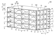
図1に示すように、熱交換器100は、第1流路11と第2流路12とが同一層内に配置された流路層10を備えている。
(Overall configuration of heat exchanger)
As shown in FIG. 1, the
熱交換器100は、少なくとも1つの流路層10を備える。図1の例では、流路層10は、互いに直交するX方向およびY方向に沿って広がる平板状の層である。流路層10は、X方向およびY方向と直交するZ方向に所定の厚みを有する。図1の例では、流路層10は、Z方向から見て矩形形状を有する。X方向は、特許請求の範囲の「第1方向」の一例である。Y方向は、特許請求の範囲の「第2方向」の一例である。Z方向は、特許請求の範囲の「第3方向」の一例である。
流路層10は、少なくとも1つの第1流路11と、少なくとも1つの第2流路12とを含む。第1流路11と第2流路12とは、互いに流体的に独立した流路である。図1の例では、流路層10は、Y方向に並ぶ複数の第1流路11と、X方向に並ぶ複数の第2流路12とを含んでいる。具体的には、流路層10は、4本の第1流路11と、4本の第2流路12とを含んでいる。流路層10に含まれる第1流路11の数と第2流路12の数とは、任意であり、互いに異なっていてもよい。
The
第1流路11は、X方向に延びる管状形状を有する。第1流路11は第1流体1を流通させるように構成されている。第1流路11は、隔壁13によって区画された中空の通路である。第1流路11がX方向に延びるとは、第1流路11が全体としてX方向に延びていることを意味し、厳密にX方向に向いた直線形状である必要はない。4本の第1流路11は、Y方向に並んでいる。
The
第2流路12は、X方向と交差するY方向に延びる管状形状を有する。第2流路12は、第1流体1と熱交換する第2流体2を流通させるように構成されている。第2流路12は、隔壁13によって区画された中空の通路である。第2流路12がY方向に延びるとは、第2流路12が全体としてY方向に延びていることを意味し、厳密にY方向に向いた直線形状である必要はない。4本の第2流路12は、X方向に並んでいる。
The
図1の例では、熱交換器100は、Z方向に配列された複数の流路層10を備えている。具体的には、4層の流路層10が設けられている。それぞれの流路層10は、同一形状を有する。隣接する流路層10の間は、平板状の隔壁13によって区画されている。図1の例では、Z方向に並ぶ4層の流路層10によって、熱交換器100のコア部3が構成されている。コア部3内において、それぞれの第1流路11を流れる第1流体1と、それぞれの第2流路12を流れる第2流体2との間で、熱交換が行われる。コア部3は、4層の流路層10によって、全体として直方体形状を有する。
In the example of FIG. 1, the
図1および図2に示すように、流路層10は、X方向側の端部に、第1端面10Aと第1端面10Aとは反対側の第2端面10Bとを有する。流路層10は、Y方向側の端部に、第3端面10Cと第3端面10Cとは反対側の第4端面10Dとを有する。
As shown in FIGS. 1 and 2, the
図2および図6に示すように、第1流路11は、流路層10内で第1端面10Aから第2端面10Bまで延びるように形成され、流路層10をX方向に貫通している。第1流路11は、一方の端部と他方の端部とを有する。第1流路11は、一方の端部に入口開口21を有し、他方の端部に出口開口22を有する。それぞれの流路層10は、X方向側の第1端面10Aに複数(4本)の第1流路11の入口開口21を有し、X方向側の第2端面10Bに複数(4本)の第1流路11の出口開口22を有する。
As shown in FIGS. 2 and 6, the
したがって、図3に示すように、第1端面10Aには、同一層内の4本の第1流路11の入口開口21がY方向に並んで設けられ、それぞれの流路層10における入口開口21がZ方向に並んで設けられている。コア部3には、4層の流路層10によって、合計16個の入口開口21がY方向およびZ方向に行列状に並んで配置されている。第2端面10Bにおける第1流路11の出口開口22の配置も同様であり、図示を省略する。コア部3には、4層の流路層10によって、合計16個の出口開口22がY方向およびZ方向に行列状に並んで配置されている。
Therefore, as shown in FIG. 3, the
図2および図4に示すように、第2流路12は、流路層10内で第3端面10Cから第4端面10Dまで延びるように形成され、流路層10をY方向に貫通している。第2流路12は、一方の端部と他方の端部とを有する。第2流路12は、一方の端部に入口開口31を有し、他方の端部に出口開口32を有する。流路層10は、Y方向側の第3端面10Cに複数の第2流路12の入口開口31を有し、Y方向側の第4端面10Dに複数の第2流路12の出口開口32を有する。
As shown in FIGS. 2 and 4, the
したがって、図5に示すように、第3端面10Cには、同一層内の4本の第2流路12の入口開口31がX方向に並んで設けられ、それぞれの流路層10における入口開口31がZ方向に並んで設けられている。コア部3には、4層の流路層10によって、合計16個の入口開口31がX方向およびZ方向に行列状に並んで配置されている。第4端面10Dにおける第2流路12の出口開口32の配置も同様であり、図示を省略する。コア部3には、4層の流路層10によって、合計16個の出口開口32がX方向およびZ方向に行列状に並んで配置されている。
Therefore, as shown in FIG. 5, the
熱交換器100には、図2に示したように、第1流路11の入口開口21、第1流路11の出口開口22、第2流路12の入口開口31、第2流路12の出口開口32を、別々に外部配管と接続するためのヘッダ部4A~4Dが設けられる。ヘッダ部4A~4Dは、対応する複数の入口開口または出口開口を、まとめて覆うように設けられる。
As shown in FIG. 2, the
ヘッダ部4Aは、第1端面10Aに形成された16個の入口開口21を覆い、外部配管から送られる第1流体1をそれぞれの入口開口21へ分配する。ヘッダ部4Bは、第2端面10Bに形成された16個の出口開口22を覆い、それぞれの出口開口22から流出する第1流体1を合流させて外部配管へ送りだす。ヘッダ部4Cは、第3端面10Cに形成された16個の入口開口31を覆い、外部配管から送られる第2流体2をそれぞれの入口開口31へ分配する。ヘッダ部4Dは、第4端面10Dに形成された16個の出口開口32を覆い、それぞれの出口開口32から流出する第2流体2を合流させて外部配管へ送りだす。
The
このように、本実施形態の熱交換器100は、第1流路11によって第1流体1を第1端面10Aから第2端面10Bに向けてX方向に流通させ、第2流路12によって第2流体2を第3端面10Cから第4端面10Dに向けてY方向に流通させて熱交換を行う、直交流型の熱交換器として構成されている。直交流型とは、熱交換を行う流体同士が互いに直交する方向に向けて流通する方式のことである。
In this way, the
(流路の構造)
次に、第1流路11および第2流路12の詳細な構造について説明する。
(Flow path structure)
Next, detailed structures of the
〈流路断面形状の変化〉
本実施形態では、第1流路11および第2流路12の各々は、流路の延びる方向に沿って流路断面積が縮小および拡大するように形成されている。なお、本明細書において、流路断面積とは、流路の延びる方向に対して直交する断面における、流路(流体が流通する空間)の面積である。
<Change in flow path cross-sectional shape>
In this embodiment, each of the
図7および図8に示すように、第1流路11は、流路断面積が縮小された第1部分23を含む。また、第1流路11は、第1部分23よりも流路断面積が拡大された第2部分24を含む。
As shown in FIGS. 7 and 8, the
第1流路11は、第1部分23において流路断面積が最小となる。第1流路11は、第2部分24において流路断面積が最大となる。第1部分23において、流路断面は、図4に示すように、台形形状となる。第2部分24において、流路断面は、図3に示すように、長方形形状となる。図7および図8に示すように、第1流路11は、第2部分24から第1部分23に至るまでに、流路断面積が縮小され、第1部分23から第2部分24に至るまでに、流路断面積が拡大される。
The
図9および図10に示すように、第2流路12は、流路断面積が縮小された第1部分33を含む。また、第2流路12は、第1部分33よりも流路断面積が拡大された第2部分34を含む。
As shown in FIGS. 9 and 10, the
第2流路12は、第1部分33において流路断面積が最小となる。第2流路12は、第2部分34において流路断面積が最大となる。第1部分33において、流路断面は、図6に示すように、台形形状となる。第2部分34において、流路断面は、図5に示すように、長方形形状となる。図9および図10に示すように、第2流路12は、第2部分34から第1部分33に至るまでに、流路断面積が縮小され、第1部分33から第2部分34に至るまでに、流路断面積が拡大される。
The
このように、第1流路11および第2流路12は、それぞれ、複数の第1部分(23、33)と、複数の第2部分(24、34)と、を有している。そして、各流路において、第1部分(23、33)と第2部分(24、34)とは、流路の延びる方向に沿って交互に配置されている。したがって、第1流路11および第2流路12の各々では、流路断面積の縮小と拡大とが、交互に生じるように形成されている。
In this way, the
また、第1流路11および第2流路12は、それぞれ、流路の端部に配置された第2部分(24、34)によって、入口開口または出口開口が構成されている。
Further, the
すなわち、第1流路11(図7、図8、図1参照)では、第1端面10Aの第2部分24によって、入口開口21が構成され、第2端面10Bの第2部分24によって、出口開口22が構成されている。同様に、第2流路12(図9、図10、図1参照)では、第3端面10Cの第2部分34によって、入口開口31が構成され、第4端面10Dの第2部分34によって、出口開口32が構成されている。
That is, in the first flow path 11 (see FIGS. 7, 8, and 1), the
〈第1流路と第2流路との交差〉
また、第1流路11および第2流路12は、流路断面積が縮小された第1部分(23、33)がX方向およびY方向と交差するZ方向に変位することにより、第1部分(23、33)において同一層内で交差している。
<Intersection of the first flow path and the second flow path>
In addition, the
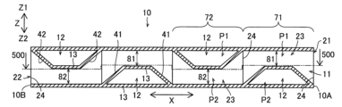
たとえば図6に示すように、第1流路11は、領域71において、第1部分23がZ1方向に偏るように変位している。そして、同じ領域71において、第2流路12の第1部分33がZ2方向に偏るように変位することにより、第1流路11と交差している。領域71では、第1流路11(第1部分23)が第2流路12のZ1方向側を跨ぐようにX方向に延びており、第2流路12(第1部分33)が第1流路11のZ2方向側をくぐるようにY方向に延びている。
For example, as shown in FIG. 6, the
また、第1流路11は、領域72において、第1部分23がZ2方向に偏るように変位している。そして、領域72において、第2流路12の第1部分33がZ1方向に偏るように変位することにより、第1流路11と交差している。領域72において、第1流路11(第1部分23)が第2流路12のZ2方向側をくぐるようにX方向に延びており、第2流路12(第1部分33)が第1流路11のZ1方向側を跨ぐようにY方向に延びている。
Further, the
第2流路12についても同様である。図4に示したように、第2流路12は、領域73において、第1部分33がZ1方向に偏るように変位し、Z2方向に偏るように変位した第1流路11と交差している。領域74では、第2流路12は、第1部分33がZ2方向に偏るように変位し、Z1方向に偏るように変位した第1流路11と交差している。
The same applies to the
本実施形態では、交差する第1流路11の第1部分23と第2流路12の第1部分33とのZ方向の位置関係が交互に入れ替わるように、第1流路11および第2流路12が蛇行している。
In this embodiment, the
つまり、図6に示したように、第1流路11では、第1部分23がZ1方向に偏り、第2流路12に対してZ1方向側に位置する領域71と、第1部分23がZ2方向に偏り、第2流路12に対してZ2方向側に位置する領域72とが、X方向に沿って交互に現れている。領域71において、第1部分23がZ方向の第1位置P1に位置し、領域72において、第1部分23がZ方向の第2位置P2に位置する。
That is, as shown in FIG. 6, in the
また、図4に示したように、第2流路12では、第1部分33がZ1方向に偏り、第1流路11に対してZ1方向側に位置する領域73と、第1部分33がZ2方向に偏り、第1流路11に対してZ2方向側に位置する領域74とが、Y方向に沿って交互に現れている。領域73において、第1部分33がZ方向の第1位置P1に位置し、領域74において、第1部分33がZ方向の第2位置P2に位置する。
Further, as shown in FIG. 4, in the
このように、第1流路11および第2流路12は、流路の延びる方向の位置に応じて、第1部分(23、33)がZ方向の第1位置P1と第2位置P2との間で変位するように蛇行している。
In this way, the
ここで、本実施形態では、第1位置P1における第1部分(23、33)のZ方向の形成範囲と、第2位置P2における第1部分(23、33)のZ方向の形成範囲とが、Z方向において重複しないようにずれている。 Here, in the present embodiment, the formation range of the first portion (23, 33) in the Z direction at the first position P1 and the formation range of the first portion (23, 33) in the Z direction at the second position P2 are different from each other. , are shifted so as not to overlap in the Z direction.
すなわち、図7に示すように、第1流路11では、第1位置P1における第1部分23は、Z方向の範囲81に亘って形成されている。第2位置P2における第1部分23は、Z方向の範囲82に亘って形成されている。Z方向において、範囲81と範囲82とが重複していない。
That is, as shown in FIG. 7, in the
同様に、第2流路12では、図9に示すように、第1位置P1における第1部分33は、Z方向の範囲81に亘って形成されている。第2位置P2における第1部分33は、Z方向の範囲82に亘って形成されている。Z方向において、範囲81と範囲82とが重複していない。
Similarly, in the
つまり、本実施形態では、第1流路11と第2流路12とが、それぞれの第1部分(23、33)において、流路層10をZ方向に2等分するように形成されており、範囲81と範囲82とが流路層10をZ方向に2等分する範囲となっている。このため、第1位置P1と第2位置P2とで、第1部分(23、33)の形成範囲が重複することがない。
That is, in the present embodiment, the
〈流路間の隔壁〉
図7~図10に示したように、第1流路11および第2流路12の各々は、流路断面積を縮小および拡大させるように屈曲した隔壁13により区画されている。第1流路11の第1部分23および第2部分24と、第2流路12の第1部分33および第2部分34とは、隔壁13によって形成されている。
<Partition wall between channels>
As shown in FIGS. 7 to 10, each of the
図7において、第1流路11は、台形断面の第2流路12のZ1方向側またはZ2方向側をX方向に横切る。隔壁13は、台形断面の第2流路12と、蛇行する第1流路11とを区画するように屈曲している。隔壁13は、台形断面の第2流路12を形成するように流路層10内に突出している。そして、流路層10内に突出した隔壁13によって、第1流路11の流路断面積が縮小した第1部分23が区画されている。
In FIG. 7, the
図9において、第2流路12は、台形断面の第1流路11のZ1方向側またはZ2方向側をY方向に横切る。隔壁13は、台形断面の第1流路11と、蛇行する第2流路12とを区画するように屈曲している。隔壁13は、台形断面の第1流路11を形成するように流路層10内に突出している。そして、流路層10内に突出した隔壁13によって、第2流路12の流路断面積が縮小した第1部分33が区画されている。
In FIG. 9, the
このように、第1流路11と第2流路12とは、同一層内で共通の隔壁13により互いに区画されている。第1流路11と第2流路12とは、隔壁13を介して互いに隣接している。そのため、隔壁13は、第1流路11と第2流路12との間で熱交換を行う際の1次伝熱面を構成する。
In this way, the
また、第1流路11および第2流路12は、流路の延びる方向の位置に応じて断面積が連続的に変化するように、傾斜した隔壁13によって区画されている。
Further, the
隔壁13は、図5および図3(図7および図9)に示したように、Z方向において流路層10の外縁部から流路層10の中心に向けて突出するように傾斜した傾斜面41、42、43、44を有する。隔壁13は、図3および図8に示したように、Y方向において流路層10の外縁部から流路層10の中心に向けて突出するように傾斜した傾斜面45、46を有する。隔壁13は、図5および図10に示したように、X方向において流路層10の外縁部から流路層10の中心に向けて突出するように傾斜した傾斜面47、48を有する。
As shown in FIGS. 5 and 3 (FIGS. 7 and 9), the
したがって、第1流路11は、隔壁13の傾斜面41、42(図7参照)によってZ方向の流路高さが連続的に変化し、隔壁13の傾斜面45、46(図8参照)によってY方向の流路幅が連続的に変化している。第1流路11は、流路の延びる方向に沿って流路高さが縮小および拡大するように形成され、流路の延びる方向に沿って流路幅が縮小および拡大するように形成されている。
Therefore, in the
同様に、第2流路12は、隔壁13の傾斜面43、44(図9参照)によってZ方向の流路高さが連続的に変化し、隔壁13の傾斜面47、48(図10参照)によってX方向の流路幅が連続的に変化している。第2流路12は、流路の延びる方向に沿って流路高さが縮小および拡大するように形成され、流路の延びる方向に沿って流路幅が縮小および拡大するように形成されている。
Similarly, in the
これにより、第1流体1は、第1流路11において、Z方向の流路高さの変化およびY方向の流路幅の変化、Z方向に蛇行する位置変化、の影響を受けて流れに3次元的な変化が生じる。同様に、第2流体2は、第2流路12において、Z方向の流路高さの変化およびX方向の流路幅の変化、Z方向に蛇行する位置変化、の影響を受けて流れに3次元的な変化が生じる。
As a result, the
〈隣接する他の流路層内の流路との位置関係〉
また、図6に示したように、第1流路11は、同一層内の第2流路12と隣接し、かつ、Z方向に隣接する他の流路層10内の第2流路12と隣接するように設けられている。図6から分かるように、第1流路11は、Z1方向およびZ2方向の一方側で同一層内の第2流路12と隣接し、Z1方向およびZ2方向の他方側で隣接する他の流路層10内の第2流路12と隔壁13を介して隣接している。
<Positional relationship with channels in other adjacent channel layers>
Further, as shown in FIG. 6, the
同様に、図4に示したように、第2流路12は、同一層内の第1流路11と隣接し、かつ、Z方向に隣接する他の流路層10内の第1流路11と隣接するように設けられている。図4から分かるように、第2流路12は、Z1方向およびZ2方向の一方側で同一層内の第1流路11と隣接し、Z1方向およびZ2方向の他方側で隣接する他の流路層10内の第1流路11と隔壁13を介して隣接している。
Similarly, as shown in FIG. 4, the
なお、図4に示したように、第1流路11は、同一層内の第2流路12と、隔壁を介してY方向の両側で隣接する。図6に示したように、第2流路12は、同一層内の第1流路11と、隔壁を介してX方向の両側で隣接する。
Note that, as shown in FIG. 4, the
このように、本実施形態では、第1流路11と第2流路12とが、全て1次伝熱面を介して隣接するように構成されている。
In this way, in this embodiment, the
(単位構造)
図1~図10に示した流路層10は、単位構造50(図11参照)を複数配列することにより構成されている。図11に示すように、単位構造50は、1つの第1流路11と、1つの第2流路12とが形成された、流路層10の最小単位である。流路層10は、単位構造50が繰り返し現れる周期的な構造を有する。
(unit structure)
The
〈単位構造の構成〉
図12は、単位構造50における第1流路11の形状と第2流路12の形状とを、別々に描いた模式図である。図11および図12に示すように、単位構造50において、X方向に延びる第1流路11とY方向に延びる第2流路12とが交差するように形成されている。したがって、1つの単位構造50のみにより、同一層内に配置される第1流路11と第2流路12とが交差する直交流型の流路層10が構成されうる。流路層10は、1つの単位構造50によって構成されていてもよい。
<Configuration of unit structure>
FIG. 12 is a schematic diagram illustrating the shape of the
図11に示す単位構造50は、X方向およびY方向に拡がるととともに、Z方向に所定の高さを有する直方体形状を有する。単位構造50のZ方向の高さが、流路層10の高さ(厚み)に相当する。単位構造50は、X方向側の一方に第1端面50Aを有し、X方向側の他方に第2端面50Bを有する。単位構造50は、Y方向側の一方に第3端面50Cを有し、Y方向側の他方に第4端面50Dを有する。
The
単位構造50において、第1流路11および第2流路12は、第1部分(23、33)よりも流路断面積が拡大された第2部分(24、34)を両端にそれぞれ有する。
In the
具体的には、第1流路11は、図16に示すように、単位構造50においてX方向に延び、単位構造50のX方向側の第1端面50Aおよび第2端面50Bに開口する。第1流路11は、単位構造50の第1端面50Aおよび第2端面50Bに、それぞれ第2部分24を有する。それぞれの第2部分24は、同一の断面形状を有する。第1流路11は、X方向の両端の2つの第2部分24の間に、第1部分23を有する。第1部分23と第2部分24との間が、図13および図17に示すように、隔壁13の傾斜面41、45および46によって接続されている。
Specifically, as shown in FIG. 16, the
第2流路12は、図14に示すように、単位構造50においてY方向に延び、単位構造50のY方向側の第3端面50Cおよび第4端面50Dに開口する。第2流路12は、単位構造50の第3端面50Cおよび第4端面50Dに、それぞれ第2部分34を有する。それぞれの第2部分34は、同一の断面形状を有する。第2流路12は、Y方向の両端の2つの第2部分34の間に、第1部分33を有する。第1部分33と第2部分34との間が、図15および図18に示すように、隔壁13の傾斜面43、47および48によって接続されている。
As shown in FIG. 14, the
単位構造50において、第1流路11の第1部分23は、第2流路12の第1部分33に対してZ方向のいずれか一方に変位し、第2流路12の第1部分33は、第1流路11の第1部分23に対してZ方向のいずれか他方に変位している。これにより、単位構造50では、第1流路11と第2流路12が、それぞれの第1部分(23、33)において互いに交差している。
In the
〈複数の単位構造の配列〉
単位構造50をX方向に配列することによって、第1流路11の流路長さが任意に設定できる。すなわち、第1流路11は、複数の単位構造50における第2部分24同士が接続されることによりX方向に延びるように構成されている。具体的には、1つの単位構造50の第2端面50Bの第2部分24と、隣り合う1つの単位構造50の第1端面50Aの第2部分24とが接続される。
<Array of multiple unit structures>
By arranging the
複数の単位構造50によって第1流路11を形成する場合、流路層10には、単位構造50のX方向の配列数に対応する数の第2流路12が形成される。第1流路11は、それぞれの第2流路12と交差する。図1および図6~図8の流路層10では、4つの単位構造50がX方向に配列されることにより、1本の第1流路11が構成されている。これにより、1本の第1流路11が、4本の第2流路12と交差している。
When the
同様に単位構造50をY方向に配列することによって、第2流路12の流路長さが任意に設定できる。すなわち、第2流路12は、複数の単位構造50における第2部分24同士が接続されることによりY方向に延びるように構成されている。具体的には、1つの単位構造50の第3端面50Cの第2部分34と、隣り合う1つの単位構造50の第4端面50Dの第2部分34とが接続される。
Similarly, by arranging the
複数の単位構造50によって第2流路12を形成する場合、流路層10には、単位構造50のY方向の配列数に対応する数の第1流路11が形成される。第2流路12は、それぞれの第1流路11と交差する。図1、図4、図9および図10の流路層10では、4つの単位構造50がY方向に配列されることにより、1本の第2流路12が構成されている。これにより、1本の第2流路12が、4本の第1流路11と交差している。
When the
〈単位構造による蛇行した流路の形成〉
図4および図6に示したように、第1流路11および第2流路12をZ方向に蛇行させる場合、流路層10は、少なくとも、第1部分(23、33)のZ方向の位置が異なる2種類の単位構造50の組み合わせによって構成されうる。
<Formation of meandering flow path by unit structure>
As shown in FIGS. 4 and 6, when the
すなわち、図19および図20の例では、単位構造50は、第1構造51と、第1構造51を反転させた第2構造52と、を含む。第1構造51と第2構造52とは、構造的には同一の形状を有する。第1構造51を、Z方向に反転させたものが、第2構造52である。なお、図11~図18は、第1構造51を示している。第2構造52は、図19および図20に示すように、第1構造51の傾斜面41、43に代えて、傾斜面42、44を含む。
That is, in the examples of FIGS. 19 and 20, the
第1構造51では、第1流路11の第1部分23がZ方向の一方側(Z1方向側)に配置され、第2流路12の第1部分33がZ方向の他方側(Z2方向側)に配置されている。つまり、第1構造51は、第1位置P1に配置された第1部分23と、第2位置P2に配置された第1部分33とを含む。図6の領域71、図4の領域74が、第1構造51によって形成されている。
In the
第2構造52では、第1流路11の第1部分23がZ方向の他方側(Z2方向側)に配置され、第2流路12の第1部分33がZ方向の一方側(Z1方向側)に配置されている。つまり、第2構造52は、第2位置P2に配置された第1部分23と、第1位置P1に配置された第1部分33とを含む。図6の領域72、図4の領域73が、第2構造52によって形成されている。
In the
そして、図19および図20に示したように、流路層10は、第1構造51と第2構造52とがX方向およびY方向の少なくとも一方に交互に並ぶように配列された構造を有する。図6に示すように、第1構造51と第2構造52とが、X方向に沿って2つずつ交互に並び、合計4つ配列されている。同様に、図4に示すように、第1構造51と第2構造52とが、Y方向に沿って2つずつ交互に並び、合計4つ配列されている。
As shown in FIGS. 19 and 20, the
つまり、図1~図10の流路層10では、X方向に4つの単位構造50が配列され、Y方向に4つの単位構造50が配列されており、16個の単位構造50によって流路層10が構成されている。
That is, in the
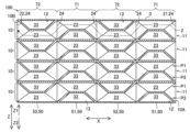
そして、16個の単位構造50の内訳として、第1構造51と第2構造52とがX方向およびY方向のそれぞれで交互に現れるように、8個ずつ設けられている。流路層10は、図2に示したように、第1構造51と第2構造52とが市松模様状に配列された構造を有する。図2では、Z1方向側(すなわち、第1位置P1)を通過する流路を実線矢印で示し、Z2方向側(すなわち、第2位置P2)を通過する流路を破線矢印で示している。実線で示された第1流路11と、破線で示された第2流路12とが交差する部分が、第1構造51により構成されている。破線で示された第1流路11と、実線で示された第2流路12とが交差する部分が、第2構造52により構成されている。
As a breakdown of the 16
このように構成された流路層10が、Z方向に配列されることにより、図1に示したコア部3が構成されている。それぞれの流路層10では、同じ単位構造50がZ方向に並ぶ。すなわち、図4および図6に示すように、それぞれの流路層10の第1構造51同士がZ方向に配列され、それぞれの流路層10の第2構造52同士がZ方向に配列されている。これにより、いずれかの流路層10の第1流路11が、Z方向に隣接する他の流路層10内の第2流路12と隣接しいずれかの流路層10の第2流路12が、Z方向に隣接する他の流路層10内の第1流路11と隣接する構造が実現される。
The
(熱交換器の形成手法)
熱交換器100のコア部3は、たとえば、積層造形法によって形成された立体構造物とされうる。より具体的には、積層造形法は、粉末積層造形法である。粉末積層造形法は、粉末材料を層状に敷き詰め、造形すべき箇所にレーザや電子ビームなどを照射して溶融、凝固させることによって層状の造形部分を形成する処理を、積層方向(造形方向)に繰り返し、層状の造形部分を積層方向に積み重ねて立体構造を造形する手法である。粉末材料は、鉄系、銅系、チタン系、アルミニウム系などの金属材料であり、重量、機械的強度、伝熱性能など観点から、たとえばアルミニウム(またはアルミニウム合金)などが好ましい。
(Heat exchanger formation method)
The
本実施形態では、コア部3が、積層造形法によって一体的に形成(単一部品として形成)された後、ヘッダ部4A~4Dと接合されることによって熱交換器100として構成されうる。また、コア部3およびヘッダ部4A~4Dを含む熱交換器100の全体が、積層造形法によって一体的に形成されうる。
In this embodiment, the
(熱交換器の作用)
以上のように構成された熱交換器100では、ヘッダ部4Aから各第1流路11に導入された第1流体1が、第1流路11の第2部分24と第1部分23とを交互に通過する。さらに、第1流体1は、第1位置P1の第1部分23と第2位置P2の第1部分23とを交互に通過するように、Z方向に蛇行して流れる。第1流体1が第1流路11内を流れる過程で、隣接する複数の第2流路12をそれぞれ流れる第2流体2との間で熱交換が行われる。熱交換の後、第1流体1は、出口開口22からヘッダ部4Bへ排出される。
(Effect of heat exchanger)
In the
そして、ヘッダ部4Cから各第2流路12に導入された第2流体2が、第2流路12の第2部分34と第1部分33とを交互に通過する。さらに、第2流体2は、第1位置P1の第1部分33と第2位置P2の第1部分33とを交互に通過するように、Z方向に蛇行して流れる。第2流体2が第2流路12内を流れる過程で、隣接する複数の第1流路11をそれぞれ流れる第1流体1との間で熱交換が行われる。熱交換の後、第2流体2は、出口開口32からヘッダ部4Dへ排出される。
The
第1流路11および第2流路12の内部では、流路断面積の変化およびZ方向の変位に伴って、流れの乱れが生じ、温度境界層が破壊されることにより熱交換が効率的に行われる。また、第1流路11と第2流路12とを区画する隔壁13が全面に亘って1次伝熱面を構成する。つまり、隣り合う流路層10同士を区画する境界だけでなく、同一層内の流路を区画する隔壁13によっても1次伝熱面が構成されているので、従来のプレートフィン型熱交換器と比較して1次伝熱面の面積が増大している。その結果、隔壁13を介した第1流体1と第2流体2との熱交換が効率的に行われる。
Inside the
(本実施形態の効果)
本実施形態では、以下のような効果を得ることができる。
(Effects of this embodiment)
In this embodiment, the following effects can be obtained.
本実施形態では、上記のように、第1流路11および第2流路12の各々が、流路断面積を縮小および拡大させつつ、さらに第1部分(23、33)においてZ方向に変位する。これにより、それぞれの流路内では、断面形状の変化に伴う2次元的な流れの変化に加えて、Z方向への流れの変化によって、3次元的に変化する流れを形成できる。その結果、熱伝達率を改善するための流れの乱れを効果的に形成できる。そして、第1流路11および第2流路12の各々に形成される第1部分(23、33)を利用し、第1部分(23、33)の位置をZ方向にずらすことによって、第1流路11と第2流路12とを同一層内で互いに交差するように形成できる。これにより、従来のプレートフィン型の熱交換器のように、第1の層と、第2の層との境界にのみ伝熱面が形成される構造(図21参照)と異なり、単一の流路層10内で第1流路11と第2流路12との伝熱面を形成できる。その結果、従来の熱交換器と同等のサイズであれば、従来の熱交換器よりも伝熱面積を増大させることができ、従来の熱交換器と同等の伝熱面積であれば、従来の熱交換器よりも熱交換器のサイズおよび重量を低減できる。以上の結果、本実施形態では、熱交換器のサイズおよび重量の増大を抑制しながら、熱交換効率を改善させることができる。
In this embodiment, as described above, each of the
また、本実施形態では、上記のように、第1流路11および第2流路12の各々が、流路断面積を縮小および拡大させるように屈曲した隔壁13により区画されているので、流路断面積を変化させるために2次伝熱面となるフィンを流路内に配置する必要がなく、第1流路11と第2流路12と隔壁13を介して直接隣接させることができる。そして、第1流路11と第2流路12とが、同一層内で共通の隔壁13により互いに区画されているので、同一層内の第1流路11と第2流路12との隔壁13によって1次伝熱面を構成することができる。これにより、第1流路11と第2流路12との1次伝熱面を効果的に増大させることができる。
Further, in this embodiment, as described above, each of the
また、本実施形態では、上記のように、第1流路11および第2流路12は、流路の延びる方向の位置に応じて断面積が連続的に変化するように、傾斜した隔壁13によって区画されているので、たとえば段差状に形成された隔壁13により流路断面積が急激に(直角に)変化するような構造と比較して、流路断面積の変化を滑らかにすることができる。これにより、第1流路11および第2流路12において、熱交換効率を改善させる流れの変化を形成しつつ、圧力損失の過度な増大を抑制できる。
Further, in the present embodiment, as described above, the
また、本実施形態では、上記のように、第1流路11がZ方向に隣接する他の流路層10内の第2流路12と隣接するように設けられ、第2流路12がZ方向に隣接する他の流路層10内の第1流路11と隣接するように設けられているので、第1流路11を同一層内だけでなく別の流路層10の第2流路12とも隣接させ、第2流路12を同一層内だけでなく別の流路層10の第1流路11と隣接させることができる。これにより、第1流路11と第2流路12との間の伝熱面積を更に増大させることができるので、熱交換効率を効果的に改善させることができる。
Further, in this embodiment, as described above, the
また、本実施形態では、上記のように、交差する第1流路11の第1部分23と第2流路12の第1部分33とのZ方向の位置関係が交互に入れ替わるように、第1流路11および第2流路12が蛇行しているので、同一層内に配置される第1流路11および第2流路12の各々を、Z方向に複数回変位させることができる。その結果、各流路において、複数回に亘ってZ方向への流れの変化を生じさせることができるので、熱交換効率を効果的に改善させることができる。
Further, in this embodiment, as described above, the
また、本実施形態では、上記のように、第1位置P1における第1部分(23、33)のZ方向の形成範囲81と、第2位置P2における第1部分(23、33)のZ方向の形成範囲82とが、Z方向において重複しないようにずれているので、第1流路11において、第1位置P1にある第1部分23と、第2位置P2にある第1部分23とをX方向に直線的に通過する領域が形成されない。第2流路12においても同様に、Y方向に直線的に通過する領域が形成されない。そのため、流体が第1位置P1と第2位置P2とを通過する過程で、確実に、Z方向への流れの変化を形成することができる。
Furthermore, in the present embodiment, as described above, the
また、本実施形態では、上記のように、第1流路11および第2流路12の各々において、第1部分(23、33)と第2部分(24、34)とが、流路の延びる方向に沿って交互に配置されているので、第1部分(23、33)における流路断面積の縮小と、第2部分(24、34)における流路断面積の拡大と、を交互に複数回発生させることができる。これにより、断面形状の変化に伴う流れの変化を効果的に発生させることができる。
Further, in this embodiment, as described above, in each of the
また、本実施形態では、上記のように、第1流路11および第2流路12の各々において、流路の端部に配置された第2部分(24、34)によって、入口開口(21、31)または出口開口(22、34)が構成されているので、流路の端部において拡大された第2部分(24、34)から流体を流路内に導入し、または流路内から導出することができる。これにより、流路断面積が変化する構造においても、流体を導入、導出するための十分な開口面積を確保できる。
Further, in this embodiment, as described above, in each of the
また、本実施形態では、上記のように、流路層10が、X方向側の第1端面10Aに複数の第1流路11の入口開口21を有し、X方向側の第2端面10Bに複数の第1流路11の出口開口22を有し、流路層10は、Y方向側の第3端面10Cに複数の第2流路12の入口開口21を有し、Y方向側の第4端面10Dに複数の第2流路12の出口開口32を有する。これにより、それぞれの流路層10の同一の端面に、流路の入口開口(21、31)または出口開口(22、32)を集約して形成できるので、ヘッダ部4A~4Dに覆われる面積と、開口部の合計面積とを近づけることができる。その結果、流路の入口開口(21、31)において圧力損失が生じることを抑制できる。
Further, in this embodiment, as described above, the
すなわち、図21に示すプレートフィン型の熱交換器の比較例のように、第1の層と第2の層とが交互に設けられる構造では、流路の入口開口が1層おきに形成され、各入口開口が外部配管との接続用のヘッダ部によってまとめて覆われる。この場合、ヘッダ部に覆われる面積A1に比べて、開口部の合計面積(2×A2)が小さいため、ヘッダ部と入口開口との間で流路が急激に絞られることになり、圧力損失が生じる。一方、図22に示す本実施形態の熱交換器100では、第1端面10Aの略全面が入口開口21となり、ヘッダ部4Aに覆われる面積A1と開口部の合計面積(4×A3)とが近付くので、流体の導入に伴う圧力損失が低減できる。図5に示した第3端面10Cについても同様である。
That is, in a structure in which the first layer and the second layer are provided alternately, as in the comparative example of the plate-fin type heat exchanger shown in FIG. 21, the inlet opening of the flow path is formed in every other layer. , each inlet opening is collectively covered by a header section for connection with external piping. In this case, since the total area of the openings (2 x A2) is smaller than the area A1 covered by the header, the flow path is rapidly constricted between the header and the inlet opening, resulting in pressure loss. occurs. On the other hand, in the
また、本実施形態では、上記のように、流路層10が、単位構造50を複数配列することにより構成されているので、同一層内で流路断面積を変化させながら互いに交差する第1流路11および第2流路12を含む流路層10を、単位構造50を並べるだけの簡単な構造で形成できる。そして、単位構造50の数を増減させるだけで、任意の流路数および任意の流路長さの熱交換器を容易に得ることができる。これにより、流路形状が3次元的に変化する新規な構造の熱交換器であっても、熱交換器の設計を極めて容易化することができる。
In addition, in this embodiment, as described above, the
また、本実施形態では、上記のように、流路層10は、第1構造51と第2構造52がX方向およびY方向に配列された構造を有するので、第1構造51と、第1構造51を反転させた第2構造52との2種類の単位構造50を配列するだけで、同一層内で第1流路11および第2流路12がZ方向に蛇行する構造を実現することができる。これにより、Z方向に蛇行する流路を含む構造であっても、容易に設計することができる。
Furthermore, in this embodiment, as described above, the
また、本実施形態では、上記のように、第1流路11は、複数の単位構造50における第2部分24同士が接続されることによりX方向に延び、第2流路12は、複数の単位構造50における第2部分34同士が接続されることによりY方向に延びるように構成されているので、単位構造50における第2部分(24、34)同士を接続するだけで、流路断面積の縮小と拡大とが交互に発生する構造を容易に実現することができる。
Further, in this embodiment, as described above, the
[変形例]
なお、今回開示された実施形態は、すべての点で例示であって制限的なものではないと考えられるべきである。本発明の範囲は、上記した実施形態の説明ではなく特許請求の範囲によって示され、さらに特許請求の範囲と均等の意味および範囲内でのすべての変更(変形例)が含まれる。
[Modified example]
Note that the embodiments disclosed this time should be considered to be illustrative in all respects and not restrictive. The scope of the present invention is indicated by the claims rather than the description of the embodiments described above, and further includes all changes (modifications) within the meaning and range equivalent to the claims.
たとえば、上記実施形態では、複数の流路層10をZ方向に配列した例を示したが、本発明はこれに限られない。本発明では、流路層10を1層だけ設けてもよい。
For example, in the embodiment described above, an example was shown in which a plurality of channel layers 10 were arranged in the Z direction, but the present invention is not limited to this. In the present invention, only one
また、上記実施形態において、単位構造50の各部の寸法は、図示したものに限られず、任意に変更してよい。たとえば、単位構造50における流路長さは任意である。上記実施形態では、第2流路12のY方向の流路長さに比べて第1流路11のX方向の流路長さが大きい(すなわち、単位構造50のX方向寸法がY方向寸法よりも大きい)例を示したが、流路長さが等しくてもよいし、第2流路12の流路長さに比べて第1流路11の流路長さが小さくてもよい。
Further, in the above embodiment, the dimensions of each part of the
また、単位構造50における第1部分23のZ方向の形成範囲は任意である。たとえば図19では、第1流路11の第1部分23と第2流路12の第1部分33とが、単位構造50のZ方向高さを2等分するように形成されているが、図23に示すように、第1部分23および第1部分33のいずれか一方の形成範囲を小さくし、いずれか他方の形成範囲を大きくしてもよい。図23では、第1部分33の形成範囲84を小さくし、第1部分23の形成範囲83を大きくした例を示しているが、逆の関係としてもよい。
Further, the formation range of the
この場合、第1部分のZ方向の形成範囲が大きくされた方の流路(図23では第1流路11)では、第1位置P1と第2位置P2とで第1部分23の形成範囲83がZ方向に重複する。そのため、流路内に、入口開口から出口開口まで直線的に貫通する領域90が形成されることになり、流路内の流れをZ方向に蛇行させる効果が低くなる。熱交換効率を向上させる観点では、上記実施形態(図19参照)のように、第1位置P1と第2位置P2とで第1部分(23、33)のZ方向の形成範囲がZ方向に重複しないようにすることが好ましい。一方、図23の構成では、流体が直線的に流通可能な領域90が部分的に形成されるため、圧力損失を低減できる。そのため、熱交換を行う第1流体1および第2流体2の種類、流量や熱交換量を考慮して、いずれかの流路における圧力損失の低減を優先する場合には、図23のように構成してもよい。
In this case, in the flow path in which the formation range of the first portion in the Z direction is increased (the
この他、たとえば単位構造50における第1部分23の長さは任意である。たとえば図16に示した第1流路11の第1部分23の長さL1は、図24に示すように、より小さい長さL2であってもよいし、より大きい長さ(図示省略)であってもよい。第2流路12の第1部分33についても同様である。
In addition, for example, the length of the
また、単位構造50における第1部分23の流路の延びる方向の位置は任意である。たとえば図16の第1流路11の第1部分23は、X方向における単位構造50の中央に配置されているが、図25に示すように、第1部分23が、第1端面50A側または第2端面50B側のいずれかに偏った位置に配置されていてもよい。第2流路12の第1部分33についても同様である。
Furthermore, the position of the
また、上記実施形態では、第1流路11および第2流路12を区画する隔壁13が、折れ線状に屈曲する例を示したが、本発明はこれに限られない。本発明では、隔壁13が、曲線状に屈曲(湾曲)していてもよい。
Further, in the above embodiment, an example was shown in which the
また、上記実施形態では、第1流路11および第2流路12の流路断面積が連続的に変化するように、傾斜した隔壁13を設けた例を示したが、本発明はこれに限られない。たとえば流路断面積が段階的に変化するように、階段状(段差状)の隔壁を設けてもよい。
Further, in the above embodiment, an example was shown in which the
また、上記実施形態では、第1流路11が、他の流路層10内の第2流路12と隣接し、第2流路12が、他の流路層10内の第1流路11と隣接する例を示したが、本発明はこれに限られない。第1流路11は、他の流路層10の第1流路11と隣接するように設けられてもよい。同様に、第2流路12は、他の流路層10の第2流路12と隣接するように設けられてもよい。
Further, in the embodiment described above, the
また、上記実施形態では、交差する第1流路11の第1部分23と第2流路12の第1部分33とのZ方向の位置関係が交互に入れ替わる例を示したが、本発明はこれに限られない。本発明では、第1流路11の第1部分23と第2流路12の第1部分33とのZ方向の位置関係が交互に入れ替わらなくてもよい。たとえば、第1構造51および第2構造52の一方のみを複数接続することにより、第1流路11または第2流路12が構成されてもよい。また、たとえば2つの第1構造51と1つの第2構造52との組み合わせなど、第1構造51の数と第2構造52の数とを異ならせて、第1流路11または第2流路12が構成されてもよい。
Further, in the above embodiment, an example was shown in which the positional relationship in the Z direction between the
また、上記実施形態では、第2部分(24、34)によって、入口開口21または出口開口22が構成されている例を示したが、第1部分(23、33)によって、入口開口21または出口開口22が構成されていてもよい。
Furthermore, in the above embodiment, the second portion (24, 34) constitutes the inlet opening 21 or the
また、上記実施形態では、流路層10の第1端面10Aに第1流路11の入口開口21を設け、第2端面10Bに第1流路11の出口開口22を設けた例を示したが、本発明はこれに限られない。たとえば第1流路11を第2端面10B側から第1端面10A側にUターンさせて、第1端面10Aに第1流路11の入口開口21と出口開口22との両方を設けてもよい。第2流路12についても同様である。
Further, in the above embodiment, an example is shown in which the inlet opening 21 of the
また、上記実施形態では、流路層10が、単位構造50を複数配列することにより構成される例を示したが、本発明はこれに限られない。単位構造50の配列によって流路層10を構成しなくてもよい。つまり、流路層10は、特定の流路形状のパターンが反復される構造ではなく、流路の一端から他端までの間が反復するパターンを有しない構造で構成されていてもよい。
Further, in the above embodiment, an example was shown in which the
また、上記実施形態では、流路層10が、第1構造51と第2構造52との2種類の単位構造50により構成される例を示したが、本発明はこれに限られない。本発明では、流路層10が、3種類以上の単位構造の組み合わせにより構成されていてもよい。
Further, in the embodiment described above, an example was shown in which the
また、上記実施形態では、流路層10が第1流路11と第2流路12とを含む例を示したが、本発明はこれに限られない。本発明では、流路層10が、第1流路11および第2流路12に加えて、さらに第3流体を流通させる第3流路を含んでもよい。流路層10は、何種類の流体を流通させるように構成されていてもよく、流体の種類に応じた数(種類)の流路を含みうる。
Further, in the embodiment described above, an example was shown in which the
1 第1流体
2 第2流体
10 流路層
10A 第1端面
10B 第2端面
10C 第3端面
10D 第4端面
11 第1流路
12 第2流路
13 隔壁
21 入口開口
22 出口開口
23 第1部分
24 第2部分
31 入口開口
32 出口開口
33 第1部分
34 第2部分
50 単位構造
50A 第1端面
50B 第2端面
50C 第3端面
50D 第4端面
51 第1構造
52 第2構造
81 形成範囲
82 形成範囲
100 熱交換器
P1 第1位置
P2 第2位置
1 First fluid 2
Claims (12)
前記第1流路および前記第2流路の各々は、流路の延びる方向に沿って流路幅及び流路高さの両方が縮小および拡大するように形成され、
前記第1流路および前記第2流路は、流路幅及び流路高さの両方が縮小された第1部分が前記第1方向および前記第2方向と交差する第3方向に変位することにより、前記第1部分において同一層内で交差している、熱交換器。 A first channel having a tubular shape extending in a first direction and through which a first fluid flows; and a first channel having a tubular shape extending in a second direction intersecting the first direction and exchanging heat with the first fluid. a second flow path through which two fluids flow; and a flow path layer arranged in the same layer;
Each of the first flow path and the second flow path is formed such that both the flow path width and the flow path height decrease and expand along the direction in which the flow path extends,
In the first flow path and the second flow path, a first portion in which both a flow path width and a flow path height are reduced is displaced in a third direction intersecting the first direction and the second direction. The heat exchanger intersects in the same layer in the first portion.
前記第1流路と前記第2流路とは、同一層内で共通の前記隔壁により互いに区画されている、請求項1に記載の熱交換器。 Each of the first flow path and the second flow path is partitioned by a partition wall that is bent so as to reduce and expand both the flow path width and the flow path height ,
The heat exchanger according to claim 1, wherein the first flow path and the second flow path are separated from each other by the common partition wall in the same layer.
前記第1流路は、同一層内の前記第2流路と隣接し、かつ、前記第3方向に隣接する他の前記流路層内の前記第2流路と隣接するように設けられ、
前記第2流路は、同一層内の前記第1流路と隣接し、かつ、前記第3方向に隣接する他の前記流路層内の前記第1流路と隣接するように設けられている、請求項1~3のいずれか1項に記載の熱交換器。 comprising a plurality of the channel layers arranged in the third direction,
The first flow path is provided adjacent to the second flow path in the same layer and adjacent to the second flow path in another flow path layer adjacent to the third direction,
The second flow path is provided adjacent to the first flow path in the same layer and adjacent to the first flow path in another flow path layer adjacent to the third direction. The heat exchanger according to any one of claims 1 to 3, wherein:
前記第1流路および前記第2流路は、流路の延びる方向に沿って複数の前記第1部分を有し、
交差する前記第1流路の前記第1部分と前記第2流路の前記第1部分との前記第3方向の位置関係が交互に入れ替わるように、前記第1流路および前記第2流路が蛇行している、請求項1~4のいずれか1項に記載の熱交換器。 The channel layer includes a plurality of first channels arranged in the second direction and a plurality of second channels arranged in the first direction,
The first flow path and the second flow path have a plurality of first portions along the direction in which the flow paths extend,
the first flow path and the second flow path such that the positional relationship in the third direction of the first portion of the first flow path and the first portion of the second flow path that intersect is alternately switched; The heat exchanger according to any one of claims 1 to 4, wherein the heat exchanger has a meandering shape.
前記第1位置における前記第1部分の前記第3方向の形成範囲と、前記第2位置における前記第1部分の前記第3方向の形成範囲とが、前記第3方向において重複しないようにずれている、請求項5に記載の熱交換器。 The first flow path and the second flow path meander such that the first portion is displaced between a first position and a second position in the third direction depending on the position in the extending direction of the flow path. death,
The formation range of the first portion in the third direction at the first position and the formation range of the first portion in the third direction at the second position are shifted so as not to overlap in the third direction. The heat exchanger according to claim 5.
前記第1流路および前記第2流路は、それぞれ、複数の前記第1部分と、前記第1部分よりも流路幅及び流路高さの両方が拡大された複数の第2部分と、を有し、
前記第1部分と前記第2部分とは、流路の延びる方向に沿って交互に配置されている、請求項1~6のいずれか1項に記載の熱交換器。 The channel layer includes a plurality of first channels arranged in the second direction and a plurality of second channels arranged in the first direction,
The first flow path and the second flow path each include a plurality of first portions, and a plurality of second portions each having both a flow path width and a flow path height larger than those of the first portion. has
The heat exchanger according to claim 1, wherein the first portion and the second portion are arranged alternately along the direction in which the flow path extends.
前記流路層は、前記第1方向側の第1端面に複数の前記第1流路の前記入口開口を有し、前記第1方向側の第2端面に複数の前記第1流路の前記出口開口を有し、
前記流路層は、前記第2方向側の第3端面に複数の前記第2流路の前記入口開口を有し、前記第2方向側の第4端面に複数の前記第2流路の前記出口開口を有する、請求項8に記載の熱交換器。 comprising a plurality of the channel layers arranged in the third direction,
The channel layer has the inlet openings of the plurality of first channels on the first end face on the first direction side, and the inlet openings of the plurality of first channels on the second end face on the first direction side. having an exit opening;
The channel layer has the inlet openings of the plurality of second channels on the third end face on the second direction side, and the inlet openings of the plurality of second channels on the fourth end face on the second direction side. 9. A heat exchanger according to claim 8, having an outlet opening.
前記第1流路の前記第1部分が前記第3方向の一方側に配置され、前記第2流路の前記第1部分が前記第3方向の他方側に配置された第1構造と、
前記第1流路の前記第1部分が前記第3方向の他方側に配置され、前記第2流路の前記第1部分が前記第3方向の一方側に配置され、前記第1構造を反転させた第2構造と、を含み、
前記流路層は、前記第1構造と前記第2構造が前記第1方向および前記第2方向の少なくとも一方に交互に並ぶように配列された構造を有する、請求項10に記載の熱交換器。 The unit structure is
a first structure in which the first portion of the first flow path is disposed on one side in the third direction, and the first portion of the second flow path is disposed on the other side in the third direction;
The first portion of the first channel is disposed on the other side in the third direction, the first portion of the second channel is disposed on one side in the third direction, and the first structure is reversed. a second structure,
The heat exchanger according to claim 10, wherein the flow path layer has a structure in which the first structure and the second structure are arranged alternately in at least one of the first direction and the second direction. .
前記第1流路および前記第2流路は、前記第1部分よりも流路幅及び流路高さの両方が拡大された第2部分を両端にそれぞれ有し、
前記第1流路は、複数の前記単位構造における前記第2部分同士が接続されることにより前記第1方向に延び、
前記第2流路は、複数の前記単位構造における前記第2部分同士が接続されることにより前記第2方向に延びるように構成されている、請求項10または11に記載の熱交換器。 In the unit structure,
The first flow path and the second flow path each have a second portion at both ends in which both a flow path width and a flow path height are larger than those of the first portion,
The first flow path extends in the first direction by connecting the second portions of the plurality of unit structures,
The heat exchanger according to claim 10 or 11, wherein the second flow path is configured to extend in the second direction by connecting the second portions of the plurality of unit structures.
Priority Applications (4)
| Application Number | Priority Date | Filing Date | Title |
|---|---|---|---|
| JP2019172439A JP7358152B2 (en) | 2019-09-24 | 2019-09-24 | Heat exchanger |
| PCT/JP2020/032918 WO2021059877A1 (en) | 2019-09-24 | 2020-08-31 | Heat exchanger |
| EP20869782.1A EP4036508B1 (en) | 2019-09-24 | 2020-08-31 | Heat exchanger |
| US17/763,039 US20220341683A1 (en) | 2019-09-24 | 2020-08-31 | Heat Exchanger |
Applications Claiming Priority (1)
| Application Number | Priority Date | Filing Date | Title |
|---|---|---|---|
| JP2019172439A JP7358152B2 (en) | 2019-09-24 | 2019-09-24 | Heat exchanger |
Publications (3)
| Publication Number | Publication Date |
|---|---|
| JP2021050838A JP2021050838A (en) | 2021-04-01 |
| JP2021050838A5 JP2021050838A5 (en) | 2022-09-20 |
| JP7358152B2 true JP7358152B2 (en) | 2023-10-10 |
Family
ID=75157983
Family Applications (1)
| Application Number | Title | Priority Date | Filing Date |
|---|---|---|---|
| JP2019172439A Active JP7358152B2 (en) | 2019-09-24 | 2019-09-24 | Heat exchanger |
Country Status (4)
| Country | Link |
|---|---|
| US (1) | US20220341683A1 (en) |
| EP (1) | EP4036508B1 (en) |
| JP (1) | JP7358152B2 (en) |
| WO (1) | WO2021059877A1 (en) |
Families Citing this family (1)
| Publication number | Priority date | Publication date | Assignee | Title |
|---|---|---|---|---|
| JP7161354B2 (en) * | 2018-09-21 | 2022-10-26 | 住友精密工業株式会社 | Heat exchanger |
Citations (6)
| Publication number | Priority date | Publication date | Assignee | Title |
|---|---|---|---|---|
| EP0984238A2 (en) | 1998-09-01 | 2000-03-08 | IP Compact AB | Heat exchanger |
| JP2002333289A (en) | 2001-05-07 | 2002-11-22 | Atago Seisakusho:Kk | Heat exchanger |
| JP2005221222A (en) | 2004-01-09 | 2005-08-18 | Xenesys Inc | Plate for heat exchange, and heat exchange unit |
| WO2010125643A1 (en) | 2009-04-28 | 2010-11-04 | 三菱電機株式会社 | Heat exchange element |
| US20150267966A1 (en) | 2014-03-18 | 2015-09-24 | Metal Industries Research & Development Centre | Adaptable heat exchanger and fabrication method thereof |
| JP2019095186A (en) | 2017-11-17 | 2019-06-20 | ゼネラル・エレクトリック・カンパニイ | Contoured wall heat exchanger |
Family Cites Families (21)
| Publication number | Priority date | Publication date | Assignee | Title |
|---|---|---|---|---|
| US5002123A (en) * | 1989-04-20 | 1991-03-26 | Microelectronics And Computer Technology Corporation | Low pressure high heat transfer fluid heat exchanger |
| US5573062A (en) * | 1992-12-30 | 1996-11-12 | The Furukawa Electric Co., Ltd. | Heat transfer tube for absorption refrigerating machine |
| US6253835B1 (en) * | 2000-02-11 | 2001-07-03 | International Business Machines Corporation | Isothermal heat sink with converging, diverging channels |
| US7871578B2 (en) * | 2005-05-02 | 2011-01-18 | United Technologies Corporation | Micro heat exchanger with thermally conductive porous network |
| US8002023B2 (en) * | 2006-03-22 | 2011-08-23 | Panasonic Corporation | Heat exchanger and its manufacturing method |
| US7866377B2 (en) * | 2006-12-20 | 2011-01-11 | The Boeing Company | Method of using minimal surfaces and minimal skeletons to make heat exchanger components |
| US9134072B2 (en) * | 2010-03-15 | 2015-09-15 | The Trustees Of Dartmouth College | Geometry of heat exchanger with high efficiency |
| KR101367071B1 (en) * | 2011-12-12 | 2014-02-25 | 삼성전기주식회사 | Heat sink |
| WO2015126483A2 (en) * | 2013-11-18 | 2015-08-27 | General Electric Company | Monolithic tube-in matrix heat exchanger |
| US10646969B2 (en) | 2015-12-02 | 2020-05-12 | Hamilton Sunstrand Corporation | Cross flow ceramic heat exchanger and method for manufacturing |
| US11243030B2 (en) * | 2016-01-13 | 2022-02-08 | Hamilton Sundstrand Corporation | Heat exchangers |
| WO2017165921A1 (en) * | 2016-03-30 | 2017-10-05 | Woodside Energy Technologies Pty Ltd | Heat exchanger and method of manufacturing a heat exchanger |
| US10208714B2 (en) * | 2016-03-31 | 2019-02-19 | Mikutay Corporation | Heat exchanger utilized as an EGR cooler in a gas recirculation system |
| US10429138B2 (en) * | 2016-08-22 | 2019-10-01 | The Boeing Company | Methods and apparatus to generate oscillating fluid flows in heat exchangers |
| FR3058510B1 (en) * | 2016-11-10 | 2019-08-16 | Safran | HEAT EXCHANGER |
| US10704841B2 (en) * | 2017-01-03 | 2020-07-07 | Titan Tensor LLC | Monolithic bicontinuous labyrinth structures and methods for their manufacture |
| US10584922B2 (en) * | 2017-02-22 | 2020-03-10 | Hamilton Sundstrand Corporation | Heat exchanges with installation flexibility |
| US10175003B2 (en) * | 2017-02-28 | 2019-01-08 | General Electric Company | Additively manufactured heat exchanger |
| US20180283795A1 (en) * | 2017-03-28 | 2018-10-04 | General Electric Company | Tubular Array Heat Exchanger |
| US10107555B1 (en) * | 2017-04-21 | 2018-10-23 | Unison Industries, Llc | Heat exchanger assembly |
| US10684080B2 (en) * | 2017-07-19 | 2020-06-16 | General Electric Company | Additively manufactured heat exchanger |
-
2019
- 2019-09-24 JP JP2019172439A patent/JP7358152B2/en active Active
-
2020
- 2020-08-31 US US17/763,039 patent/US20220341683A1/en active Pending
- 2020-08-31 EP EP20869782.1A patent/EP4036508B1/en active Active
- 2020-08-31 WO PCT/JP2020/032918 patent/WO2021059877A1/en unknown
Patent Citations (6)
| Publication number | Priority date | Publication date | Assignee | Title |
|---|---|---|---|---|
| EP0984238A2 (en) | 1998-09-01 | 2000-03-08 | IP Compact AB | Heat exchanger |
| JP2002333289A (en) | 2001-05-07 | 2002-11-22 | Atago Seisakusho:Kk | Heat exchanger |
| JP2005221222A (en) | 2004-01-09 | 2005-08-18 | Xenesys Inc | Plate for heat exchange, and heat exchange unit |
| WO2010125643A1 (en) | 2009-04-28 | 2010-11-04 | 三菱電機株式会社 | Heat exchange element |
| US20150267966A1 (en) | 2014-03-18 | 2015-09-24 | Metal Industries Research & Development Centre | Adaptable heat exchanger and fabrication method thereof |
| JP2019095186A (en) | 2017-11-17 | 2019-06-20 | ゼネラル・エレクトリック・カンパニイ | Contoured wall heat exchanger |
Also Published As
| Publication number | Publication date |
|---|---|
| US20220341683A1 (en) | 2022-10-27 |
| EP4036508A1 (en) | 2022-08-03 |
| WO2021059877A1 (en) | 2021-04-01 |
| JP2021050838A (en) | 2021-04-01 |
| EP4036508C0 (en) | 2024-02-07 |
| EP4036508B1 (en) | 2024-02-07 |
| EP4036508A4 (en) | 2022-11-16 |
Similar Documents
| Publication | Publication Date | Title |
|---|---|---|
| US11965699B2 (en) | Heat exchangers | |
| US11802742B2 (en) | Heat exchanger | |
| US3521707A (en) | Heat exchangers | |
| US8240365B2 (en) | Heat exchanger | |
| JP7480487B2 (en) | Heat exchanger | |
| KR101655889B1 (en) | Heat exchange reactor and method for producing the same | |
| WO2016190445A1 (en) | Heat exchanger tank structure and production method therefor | |
| KR20180113589A (en) | A circulating duct for transferring the fluid of the heat exchanger, and a heat exchanger | |
| JP7358152B2 (en) | Heat exchanger | |
| WO2017002819A1 (en) | Inner fin for heat exchanger | |
| JP4504092B2 (en) | Plate heat exchanger | |
| JP5468827B2 (en) | Oil cooler | |
| JP4857074B2 (en) | Plate type heat exchanger | |
| JP7247251B2 (en) | Heat exchanger | |
| JP2006266528A (en) | Flat tube for heat exchanger | |
| JP7408779B2 (en) | heat exchange system | |
| JP6013208B2 (en) | Catalytic reactor | |
| JP5958917B2 (en) | Finned tube heat exchanger | |
| JP2013127341A (en) | Heat exchanger | |
| JP2021050838A5 (en) | ||
| JP2008082672A (en) | Heat exchanger | |
| JP2952593B1 (en) | Stacked heat exchanger | |
| JP2005061778A (en) | Evaporator | |
| CN112146484A (en) | Plate heat exchanger | |
| JP2010175217A (en) | Porous tube for heat exchange |
Legal Events
| Date | Code | Title | Description |
|---|---|---|---|
| A521 | Request for written amendment filed |
Free format text: JAPANESE INTERMEDIATE CODE: A523 Effective date: 20220909 |
|
| A621 | Written request for application examination |
Free format text: JAPANESE INTERMEDIATE CODE: A621 Effective date: 20220909 |
|
| TRDD | Decision of grant or rejection written | ||
| A01 | Written decision to grant a patent or to grant a registration (utility model) |
Free format text: JAPANESE INTERMEDIATE CODE: A01 Effective date: 20230926 |
|
| A61 | First payment of annual fees (during grant procedure) |
Free format text: JAPANESE INTERMEDIATE CODE: A61 Effective date: 20230927 |
|
| R150 | Certificate of patent or registration of utility model |
Ref document number: 7358152 Country of ref document: JP Free format text: JAPANESE INTERMEDIATE CODE: R150 |