EP3176503A1 - Heat sink, backlight module and display module - Google Patents
Heat sink, backlight module and display module Download PDFInfo
- Publication number
- EP3176503A1 EP3176503A1 EP14898370.3A EP14898370A EP3176503A1 EP 3176503 A1 EP3176503 A1 EP 3176503A1 EP 14898370 A EP14898370 A EP 14898370A EP 3176503 A1 EP3176503 A1 EP 3176503A1
- Authority
- EP
- European Patent Office
- Prior art keywords
- radiating
- mounting portion
- radiator
- pipelines
- backlight module
- Prior art date
- Legal status (The legal status is an assumption and is not a legal conclusion. Google has not performed a legal analysis and makes no representation as to the accuracy of the status listed.)
- Granted
Links
Images

Classifications
-
- G—PHYSICS
- G02—OPTICS
- G02B—OPTICAL ELEMENTS, SYSTEMS OR APPARATUS
- G02B6/00—Light guides; Structural details of arrangements comprising light guides and other optical elements, e.g. couplings
- G02B6/0001—Light guides; Structural details of arrangements comprising light guides and other optical elements, e.g. couplings specially adapted for lighting devices or systems
- G02B6/0011—Light guides; Structural details of arrangements comprising light guides and other optical elements, e.g. couplings specially adapted for lighting devices or systems the light guides being planar or of plate-like form
- G02B6/0081—Mechanical or electrical aspects of the light guide and light source in the lighting device peculiar to the adaptation to planar light guides, e.g. concerning packaging
- G02B6/0085—Means for removing heat created by the light source from the package
-
- F—MECHANICAL ENGINEERING; LIGHTING; HEATING; WEAPONS; BLASTING
- F21—LIGHTING
- F21V—FUNCTIONAL FEATURES OR DETAILS OF LIGHTING DEVICES OR SYSTEMS THEREOF; STRUCTURAL COMBINATIONS OF LIGHTING DEVICES WITH OTHER ARTICLES, NOT OTHERWISE PROVIDED FOR
- F21V29/00—Protecting lighting devices from thermal damage; Cooling or heating arrangements specially adapted for lighting devices or systems
- F21V29/50—Cooling arrangements
- F21V29/502—Cooling arrangements characterised by the adaptation for cooling of specific components
- F21V29/503—Cooling arrangements characterised by the adaptation for cooling of specific components of light sources
-
- F—MECHANICAL ENGINEERING; LIGHTING; HEATING; WEAPONS; BLASTING
- F21—LIGHTING
- F21V—FUNCTIONAL FEATURES OR DETAILS OF LIGHTING DEVICES OR SYSTEMS THEREOF; STRUCTURAL COMBINATIONS OF LIGHTING DEVICES WITH OTHER ARTICLES, NOT OTHERWISE PROVIDED FOR
- F21V29/00—Protecting lighting devices from thermal damage; Cooling or heating arrangements specially adapted for lighting devices or systems
- F21V29/50—Cooling arrangements
- F21V29/51—Cooling arrangements using condensation or evaporation of a fluid, e.g. heat pipes
-
- F—MECHANICAL ENGINEERING; LIGHTING; HEATING; WEAPONS; BLASTING
- F21—LIGHTING
- F21V—FUNCTIONAL FEATURES OR DETAILS OF LIGHTING DEVICES OR SYSTEMS THEREOF; STRUCTURAL COMBINATIONS OF LIGHTING DEVICES WITH OTHER ARTICLES, NOT OTHERWISE PROVIDED FOR
- F21V29/00—Protecting lighting devices from thermal damage; Cooling or heating arrangements specially adapted for lighting devices or systems
- F21V29/50—Cooling arrangements
- F21V29/56—Cooling arrangements using liquid coolants
-
- G—PHYSICS
- G02—OPTICS
- G02F—OPTICAL DEVICES OR ARRANGEMENTS FOR THE CONTROL OF LIGHT BY MODIFICATION OF THE OPTICAL PROPERTIES OF THE MEDIA OF THE ELEMENTS INVOLVED THEREIN; NON-LINEAR OPTICS; FREQUENCY-CHANGING OF LIGHT; OPTICAL LOGIC ELEMENTS; OPTICAL ANALOGUE/DIGITAL CONVERTERS
- G02F1/00—Devices or arrangements for the control of the intensity, colour, phase, polarisation or direction of light arriving from an independent light source, e.g. switching, gating or modulating; Non-linear optics
- G02F1/01—Devices or arrangements for the control of the intensity, colour, phase, polarisation or direction of light arriving from an independent light source, e.g. switching, gating or modulating; Non-linear optics for the control of the intensity, phase, polarisation or colour
- G02F1/13—Devices or arrangements for the control of the intensity, colour, phase, polarisation or direction of light arriving from an independent light source, e.g. switching, gating or modulating; Non-linear optics for the control of the intensity, phase, polarisation or colour based on liquid crystals, e.g. single liquid crystal display cells
- G02F1/133—Constructional arrangements; Operation of liquid crystal cells; Circuit arrangements
- G02F1/1333—Constructional arrangements; Manufacturing methods
- G02F1/133308—Support structures for LCD panels, e.g. frames or bezels
-
- G—PHYSICS
- G02—OPTICS
- G02F—OPTICAL DEVICES OR ARRANGEMENTS FOR THE CONTROL OF LIGHT BY MODIFICATION OF THE OPTICAL PROPERTIES OF THE MEDIA OF THE ELEMENTS INVOLVED THEREIN; NON-LINEAR OPTICS; FREQUENCY-CHANGING OF LIGHT; OPTICAL LOGIC ELEMENTS; OPTICAL ANALOGUE/DIGITAL CONVERTERS
- G02F1/00—Devices or arrangements for the control of the intensity, colour, phase, polarisation or direction of light arriving from an independent light source, e.g. switching, gating or modulating; Non-linear optics
- G02F1/01—Devices or arrangements for the control of the intensity, colour, phase, polarisation or direction of light arriving from an independent light source, e.g. switching, gating or modulating; Non-linear optics for the control of the intensity, phase, polarisation or colour
- G02F1/13—Devices or arrangements for the control of the intensity, colour, phase, polarisation or direction of light arriving from an independent light source, e.g. switching, gating or modulating; Non-linear optics for the control of the intensity, phase, polarisation or colour based on liquid crystals, e.g. single liquid crystal display cells
- G02F1/133—Constructional arrangements; Operation of liquid crystal cells; Circuit arrangements
- G02F1/1333—Constructional arrangements; Manufacturing methods
- G02F1/133382—Heating or cooling of liquid crystal cells other than for activation, e.g. circuits or arrangements for temperature control, stabilisation or uniform distribution over the cell
- G02F1/133385—Heating or cooling of liquid crystal cells other than for activation, e.g. circuits or arrangements for temperature control, stabilisation or uniform distribution over the cell with cooling means, e.g. fans
-
- G—PHYSICS
- G02—OPTICS
- G02F—OPTICAL DEVICES OR ARRANGEMENTS FOR THE CONTROL OF LIGHT BY MODIFICATION OF THE OPTICAL PROPERTIES OF THE MEDIA OF THE ELEMENTS INVOLVED THEREIN; NON-LINEAR OPTICS; FREQUENCY-CHANGING OF LIGHT; OPTICAL LOGIC ELEMENTS; OPTICAL ANALOGUE/DIGITAL CONVERTERS
- G02F1/00—Devices or arrangements for the control of the intensity, colour, phase, polarisation or direction of light arriving from an independent light source, e.g. switching, gating or modulating; Non-linear optics
- G02F1/01—Devices or arrangements for the control of the intensity, colour, phase, polarisation or direction of light arriving from an independent light source, e.g. switching, gating or modulating; Non-linear optics for the control of the intensity, phase, polarisation or colour
- G02F1/13—Devices or arrangements for the control of the intensity, colour, phase, polarisation or direction of light arriving from an independent light source, e.g. switching, gating or modulating; Non-linear optics for the control of the intensity, phase, polarisation or colour based on liquid crystals, e.g. single liquid crystal display cells
- G02F1/133—Constructional arrangements; Operation of liquid crystal cells; Circuit arrangements
- G02F1/1333—Constructional arrangements; Manufacturing methods
- G02F1/1335—Structural association of cells with optical devices, e.g. polarisers or reflectors
- G02F1/1336—Illuminating devices
- G02F1/133615—Edge-illuminating devices, i.e. illuminating from the side
-
- G—PHYSICS
- G02—OPTICS
- G02B—OPTICAL ELEMENTS, SYSTEMS OR APPARATUS
- G02B6/00—Light guides; Structural details of arrangements comprising light guides and other optical elements, e.g. couplings
- G02B6/0001—Light guides; Structural details of arrangements comprising light guides and other optical elements, e.g. couplings specially adapted for lighting devices or systems
- G02B6/0011—Light guides; Structural details of arrangements comprising light guides and other optical elements, e.g. couplings specially adapted for lighting devices or systems the light guides being planar or of plate-like form
- G02B6/0066—Light guides; Structural details of arrangements comprising light guides and other optical elements, e.g. couplings specially adapted for lighting devices or systems the light guides being planar or of plate-like form characterised by the light source being coupled to the light guide
- G02B6/0068—Arrangements of plural sources, e.g. multi-colour light sources
-
- G—PHYSICS
- G02—OPTICS
- G02F—OPTICAL DEVICES OR ARRANGEMENTS FOR THE CONTROL OF LIGHT BY MODIFICATION OF THE OPTICAL PROPERTIES OF THE MEDIA OF THE ELEMENTS INVOLVED THEREIN; NON-LINEAR OPTICS; FREQUENCY-CHANGING OF LIGHT; OPTICAL LOGIC ELEMENTS; OPTICAL ANALOGUE/DIGITAL CONVERTERS
- G02F1/00—Devices or arrangements for the control of the intensity, colour, phase, polarisation or direction of light arriving from an independent light source, e.g. switching, gating or modulating; Non-linear optics
- G02F1/01—Devices or arrangements for the control of the intensity, colour, phase, polarisation or direction of light arriving from an independent light source, e.g. switching, gating or modulating; Non-linear optics for the control of the intensity, phase, polarisation or colour
- G02F1/13—Devices or arrangements for the control of the intensity, colour, phase, polarisation or direction of light arriving from an independent light source, e.g. switching, gating or modulating; Non-linear optics for the control of the intensity, phase, polarisation or colour based on liquid crystals, e.g. single liquid crystal display cells
- G02F1/133—Constructional arrangements; Operation of liquid crystal cells; Circuit arrangements
- G02F1/1333—Constructional arrangements; Manufacturing methods
- G02F1/133308—Support structures for LCD panels, e.g. frames or bezels
- G02F1/133314—Back frames
-
- G—PHYSICS
- G02—OPTICS
- G02F—OPTICAL DEVICES OR ARRANGEMENTS FOR THE CONTROL OF LIGHT BY MODIFICATION OF THE OPTICAL PROPERTIES OF THE MEDIA OF THE ELEMENTS INVOLVED THEREIN; NON-LINEAR OPTICS; FREQUENCY-CHANGING OF LIGHT; OPTICAL LOGIC ELEMENTS; OPTICAL ANALOGUE/DIGITAL CONVERTERS
- G02F1/00—Devices or arrangements for the control of the intensity, colour, phase, polarisation or direction of light arriving from an independent light source, e.g. switching, gating or modulating; Non-linear optics
- G02F1/01—Devices or arrangements for the control of the intensity, colour, phase, polarisation or direction of light arriving from an independent light source, e.g. switching, gating or modulating; Non-linear optics for the control of the intensity, phase, polarisation or colour
- G02F1/13—Devices or arrangements for the control of the intensity, colour, phase, polarisation or direction of light arriving from an independent light source, e.g. switching, gating or modulating; Non-linear optics for the control of the intensity, phase, polarisation or colour based on liquid crystals, e.g. single liquid crystal display cells
- G02F1/133—Constructional arrangements; Operation of liquid crystal cells; Circuit arrangements
- G02F1/1333—Constructional arrangements; Manufacturing methods
- G02F1/133382—Heating or cooling of liquid crystal cells other than for activation, e.g. circuits or arrangements for temperature control, stabilisation or uniform distribution over the cell
-
- G—PHYSICS
- G02—OPTICS
- G02F—OPTICAL DEVICES OR ARRANGEMENTS FOR THE CONTROL OF LIGHT BY MODIFICATION OF THE OPTICAL PROPERTIES OF THE MEDIA OF THE ELEMENTS INVOLVED THEREIN; NON-LINEAR OPTICS; FREQUENCY-CHANGING OF LIGHT; OPTICAL LOGIC ELEMENTS; OPTICAL ANALOGUE/DIGITAL CONVERTERS
- G02F1/00—Devices or arrangements for the control of the intensity, colour, phase, polarisation or direction of light arriving from an independent light source, e.g. switching, gating or modulating; Non-linear optics
- G02F1/01—Devices or arrangements for the control of the intensity, colour, phase, polarisation or direction of light arriving from an independent light source, e.g. switching, gating or modulating; Non-linear optics for the control of the intensity, phase, polarisation or colour
- G02F1/13—Devices or arrangements for the control of the intensity, colour, phase, polarisation or direction of light arriving from an independent light source, e.g. switching, gating or modulating; Non-linear optics for the control of the intensity, phase, polarisation or colour based on liquid crystals, e.g. single liquid crystal display cells
- G02F1/133—Constructional arrangements; Operation of liquid crystal cells; Circuit arrangements
- G02F1/1333—Constructional arrangements; Manufacturing methods
- G02F1/1335—Structural association of cells with optical devices, e.g. polarisers or reflectors
- G02F1/1336—Illuminating devices
- G02F1/133628—Illuminating devices with cooling means
Definitions
- the present invention relates to the field of radiating devices, and in particular, to a radiator, a backlight module and a display module.
- a backlight module with a single short side due to decrease of the number of the LED lamps and decrease of the number of the radiator, reduces the cost of the backlight module, and also avoids the problem of light leak of liquid crystal glass caused by deformation and bulge of the light guide plate of the backlight module with two short sides, and thus the solution of backlight with a single short side is widely applied to TV design.
- the cost of the radiator is generally very high, the heat is limited to the root of the radiator, radiation is not smooth, it is easy to heat the front frame of the display module, scald easily occurs when the front frame is touched, and a potential safety hazard exists.
- a main objective of the present invention is to solve the technical problem that the existing radiator does not have a good radiating effect.
- the present invention provides a radiator, wherein the radiator includes a mounting portion used for mounting a heat source, a radiating portion connected with the mounting portion and used for absorbing heat transferred by the mounting portion, the radiating portion is internally provided with multiple radiating pipelines, the radiating pipelines are internally injected with liquid, and the liquid in the radiating pipelines is gasified after absorbing heat on one end where the radiating portion is close to the mounting portion, and in the radiating pipelines, moves from one end where the radiating portion is close to the mounting portion towards one end where the radiating portion is away from the mounting portion.
- the radiating pipelines include a main pipeline unit disposed at the one end where the radiating portion is close to the mounting portion, multiple sub-pipeline units in communication with the main pipeline unit and a liquid injection pipeline in communication with the sub-pipeline units and located on the one end where the radiating portion is away from the mounting portion.
- the multiple sub-pipeline units are spaced apart.
- the profile of each of the sub-pipeline units is honeycomb-like.
- the present invention further provides a backlight module, wherein the backlight module includes a body, and a radiator mounted into the body, the radiator includes a mounting portion used for mounting a heat source, and a radiating portion connected with the mounting portion and used for absorbing heat transferred by the mounting portion, the radiating portion is internally provided with multiple radiating pipelines, the radiating pipelines are internally injected with liquid, and the liquid in the radiating pipelines is gasified after absorbing heat on one end where the radiating portion is close to the mounting portion, and in the radiating pipelines, moves from one end where the radiating portion is close to the mounting portion towards one end where the radiating portion is away from the mounting portion.
- the body includes a back plate, a backlight source mounted in the back plate, and a light guide plate mounted in the back plate, the radiator is mounted on the back plate, and the backlight source is mounted on the radiator.
- the backlight source is glued to the radiator through a radiating glue.
- the backlight source is a linear LED light bar
- the LED light bar includes a PCB board and multiple LED lamps mounted and electrically connected to the PCB board
- the PCB board is glued to the radiator through the radiating glue.
- the backlight module further includes a plastic frame mounted onto the back plate.
- the present invention further provides a display module, wherein the display module includes a backlight module, a display panel mounted onto the backlight module, and a front frame mounted onto the display panel;
- the backlight module includes a body, and a radiator mounted in the body, the radiator includes a mounting portion used for mounting a heat source, and a radiating portion connected with the mounting portion and used for absorbing heat transferred by the mounting portion, the radiating portion is internally provided with multiple radiating pipelines, the radiating pipelines are internally injected with liquid, and the liquid in the radiating pipelines is gasified after absorbing heat on one end where the radiating portion is close to the mounting portion, and in the radiating pipelines, moves from one end where the radiating portion is close to the mounting portion towards one end where the radiating portion is away from the mounting portion.
- the radiator, the backlight module and the display module of the present invention by injecting liquid into the radiating pipelines of the radiator, wherein the liquid is gasified after absorbing heat and moves in the radiating pipelines, achieves transfer of the heat, effectively improves the heat transfer effect, and effectively enhances the radiating effect.
- the present invention provides a radiator.
- FIG. 1 is a three-dimensional schematic structural diagram of a radiator according to the present invention.
- the radiator includes a mounting portion 220 used for mounting a heat source, and a radiating portion 240 connected with the mounting portion 220 and used for absorbing heat transferred by the mounting portion 220, the radiating portion 240 is internally provided with multiple radiating pipelines 260, the radiating pipelines 260 are internally injected with liquid, and the liquid in the radiating pipelines 260 is gasified after absorbing heat on one end where the radiating portion 240 is close to the mounting portion 220, and in the radiating pipelines 260, moves from one end where the radiating portion 240 is close to the mounting portion 220 towards one end where the radiating portion 240 is away from the mounting portion 220, to achieve transfer of the heat.
- the liquid in the radiating pipelines 260 absorbs heat and is gasified, the liquid is mixed with bubbles to form an oscillatory wave, the oscillatory wave moves along the radiating pipelines 260 and collides with pipe walls of the radiating pipelines 260 in the radiating pipelines 260, to exchange heat, and at the same time, oscillation is excited, to form a resonance wave, thus increasing a heat exchange speed, accelerating transfer of the heat to the distal end, and effectively reducing temperature gradient of the radiator.
- the radiator is formed by press fit of two aluminum plates at a certain temperature, specifically, a pipeline pattern is first designed on a surface of one aluminum plate, and a press-fit material is sprayed on the surface of the aluminum plate, then another aluminum plate is covered thereon, and the two aluminum plates are press-fit into a whole at a certain temperature, then are blown up into a designed radiating pipeline shape through high pressure gas charging, a small amount of liquid at certain pressure is fed into the radiating pipeline, an injection port is sealed then, and a bending operation is performed, to make an "L"-type radiator.
- the radiating pipelines 260 include a main pipeline unit 262 disposed at the one end where the radiating portion 240 is close to the mounting portion 220, multiple sub-pipeline units 264 in communication with the main pipeline unit 262 and a liquid injection pipeline 266 in communication with the sub-pipeline units 264 and located on the one end where the radiating portion 240 is away from the mounting portion 220.
- there are three radiating pipelines 260 the three radiating pipelines 260 are spaced apart, that is, a gap 265 is disposed between two adjacent sub-pipeline units 264, to cause that heat of each sub-pipeline unit 264 will not be transferred to another sub-pipeline unit 264 adjacent thereto, thus avoiding the problem of uneven radiation.
- the profile of each of the sub-pipeline units 264 is honeycomb-like, that is, the sub-pipeline unit 264 is formed by mutual communication of multiple hexagonal pipelines, effectively increasing the radiation area and improving the heat transfer effect.
- the present invention further provides a backlight module.
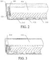
- FIG. 2 is a three-dimensional schematic structural diagram of a backlight module according to the present invention.
- the backlight module includes a body, and a radiator mounted into the body, the radiator includes all the technical solutions in the embodiment shown in FIG. 1 , and reference can be made to the aforementioned embodiment for its detailed structure and beneficial effects brought about, which are not repeated herein.
- the body includes a back plate 420, a backlight source 440 mounted in the back plate 420, and a light guide plate 460 mounted in the back plate 420, the radiator is mounted on the back plate 420, and the backlight source 440 is mounted on the radiator.
- the backlight module is a side backlight module, that is, the backlight source 440 is located on a side edge of the light guide plate 460.
- the radiating portion 240 of the radiator is fixed onto a bottom plate of the back plate 420 in a manner such as screw locking, and the backlight source 440 is mounted onto the mounting portion 220 on an in-light surface side.
- Heat produced by the backlight source 440 is transferred to the radiating portion 240 through the mounting portion 220, and the liquid in the radiating pipelines 260 located in the radiating portion 240 is gasified after absorbing the heat and, in the radiating pipelines 260, moves from one end where the radiating portion 240 is close to the mounting portion 220 towards one end where the radiating portion 240 is away from the mounting portion 220, to achieve transfer of the heat.
- the liquid in the radiating pipelines 260 absorbs heat and is gasified, the liquid is mixed with bubbles to form an oscillatory wave, the oscillatory wave moves along the radiating pipelines 260 and collides with pipe walls of the radiating pipelines 260 in the radiating pipelines 260, to exchange heat, and at the same time, oscillation is excited, to form a resonance wave, thus increasing a heat exchange speed, accelerating transfer of the heat to the distal end, effectively reducing temperature gradient of the radiator, thereby effectively lowering the temperature of the backlight source 440, and enhancing the service life of the backlight source 440.
- the backlight source 440 is fixed onto the radiator through adhesion, and preferably, the backlight source 440 is glued to the radiator through a radiating glue, to further enhance the heat transfer effect and reduce the temperature of the backlight source 440.
- the backlight source 440 is a linear LED light bar
- the LED light bar includes a PCB board and multiple LED lamps mounted and electrically connected to the PCB board, and the PCB board is glued to the radiator through the radiating glue.
- the LED lamps emit light, and the light enters into the light guide plate 460 from an in-light surface of the light guide plate 460, propagates in the light guide plate 460, and is finally emitted out from an out-light surface of the light guide plate 460, to convert a point light source to a surface light source.
- the backlight module further includes a plastic frame 480 mounted onto the back plate 420, the plastic frame 480 is disposed above the back plate 420 and is provided with an opening corresponding to the out-light surface of the light guide plate 460, and when assembled into a display module, a display panel is disposed on the plastic frame 480 and the light guide plate 460 provides a surface light source for the display panel.
- the present invention further provides a display module.
- FIG. 3 is a three-dimensional schematic structural diagram of a display module according to the present invention.
- the display module includes a backlight module, a display panel 600 mounted onto the backlight module, and a front frame 800 mounted onto the display panel 600, the backlight module includes all the technical solutions in the embodiment shown in FIG. 2 , and reference can be made to the aforementioned embodiment for its detailed structure and beneficial effects brought about, which are not repeated herein.
Landscapes
- Physics & Mathematics (AREA)
- Nonlinear Science (AREA)
- General Physics & Mathematics (AREA)
- Optics & Photonics (AREA)
- Mathematical Physics (AREA)
- Chemical & Material Sciences (AREA)
- Crystallography & Structural Chemistry (AREA)
- Engineering & Computer Science (AREA)
- General Engineering & Computer Science (AREA)
- Planar Illumination Modules (AREA)
- Liquid Crystal (AREA)
- Arrangement Of Elements, Cooling, Sealing, Or The Like Of Lighting Devices (AREA)
Abstract
Description
- The present invention relates to the field of radiating devices, and in particular, to a radiator, a backlight module and a display module.
- Compared with a backlight module with two short sides, a backlight module with a single short side, due to decrease of the number of the LED lamps and decrease of the number of the radiator, reduces the cost of the backlight module, and also avoids the problem of light leak of liquid crystal glass caused by deformation and bulge of the light guide plate of the backlight module with two short sides, and thus the solution of backlight with a single short side is widely applied to TV design.
- As the number of the LED lamps in the backlight module with a single short side is reduced, it is necessary to increase power of the single LED lamp to meet the brightness requirement of the whole machine, this causes the power of the single LED lamp to be too great, radiation to be difficult and the temperature to be very high, and the life of the LED is reduced. Radiation of the common backlight module with a single short side is pasting a LED light bar to a wide and thicker profile radiator and then affixing the LED light bar onto the back plate, the thicker radiator causes the thickness of the TV to become large, affecting the appearance and not conductive to thinning. Moreover, the cost of the radiator is generally very high, the heat is limited to the root of the radiator, radiation is not smooth, it is easy to heat the front frame of the display module, scald easily occurs when the front frame is touched, and a potential safety hazard exists.
- A main objective of the present invention is to solve the technical problem that the existing radiator does not have a good radiating effect.
- To achieve the foregoing objective, the present invention provides a radiator, wherein the radiator includes a mounting portion used for mounting a heat source, a radiating portion connected with the mounting portion and used for absorbing heat transferred by the mounting portion, the radiating portion is internally provided with multiple radiating pipelines, the radiating pipelines are internally injected with liquid, and the liquid in the radiating pipelines is gasified after absorbing heat on one end where the radiating portion is close to the mounting portion, and in the radiating pipelines, moves from one end where the radiating portion is close to the mounting portion towards one end where the radiating portion is away from the mounting portion.
- Preferably, the radiating pipelines include a main pipeline unit disposed at the one end where the radiating portion is close to the mounting portion, multiple sub-pipeline units in communication with the main pipeline unit and a liquid injection pipeline in communication with the sub-pipeline units and located on the one end where the radiating portion is away from the mounting portion.
- Preferably, the multiple sub-pipeline units are spaced apart.
- Preferably, the profile of each of the sub-pipeline units is honeycomb-like.
- In addition, to achieve the foregoing objective, the present invention further provides a backlight module, wherein the backlight module includes a body, and a radiator mounted into the body, the radiator includes a mounting portion used for mounting a heat source, and a radiating portion connected with the mounting portion and used for absorbing heat transferred by the mounting portion, the radiating portion is internally provided with multiple radiating pipelines, the radiating pipelines are internally injected with liquid, and the liquid in the radiating pipelines is gasified after absorbing heat on one end where the radiating portion is close to the mounting portion, and in the radiating pipelines, moves from one end where the radiating portion is close to the mounting portion towards one end where the radiating portion is away from the mounting portion.
- Preferably, the body includes a back plate, a backlight source mounted in the back plate, and a light guide plate mounted in the back plate, the radiator is mounted on the back plate, and the backlight source is mounted on the radiator.
- Preferably, the backlight source is glued to the radiator through a radiating glue.
- Preferably, the backlight source is a linear LED light bar, the LED light bar includes a PCB board and multiple LED lamps mounted and electrically connected to the PCB board, and the PCB board is glued to the radiator through the radiating glue.
- Preferably, the backlight module further includes a plastic frame mounted onto the back plate.
- In addition, to achieve the foregoing objective, the present invention further provides a display module, wherein the display module includes a backlight module, a display panel mounted onto the backlight module, and a front frame mounted onto the display panel; the backlight module includes a body, and a radiator mounted in the body, the radiator includes a mounting portion used for mounting a heat source, and a radiating portion connected with the mounting portion and used for absorbing heat transferred by the mounting portion, the radiating portion is internally provided with multiple radiating pipelines, the radiating pipelines are internally injected with liquid, and the liquid in the radiating pipelines is gasified after absorbing heat on one end where the radiating portion is close to the mounting portion, and in the radiating pipelines, moves from one end where the radiating portion is close to the mounting portion towards one end where the radiating portion is away from the mounting portion.
- The radiator, the backlight module and the display module of the present invention, by injecting liquid into the radiating pipelines of the radiator, wherein the liquid is gasified after absorbing heat and moves in the radiating pipelines, achieves transfer of the heat, effectively improves the heat transfer effect, and effectively enhances the radiating effect.
-
-
FIG. 1 is a three-dimensional schematic structural diagram of a radiator according to the present invention; -
FIG. 2 is a three-dimensional schematic structural diagram of a backlight module according to the present invention; and -
FIG. 3 is a three-dimensional schematic structural diagram of a display module according to the present invention. - The objective implementation, functional characteristics and advantages of the present invention are further described with reference to the accompanying drawings in combination with embodiments.
- It should be understood that the specific embodiments described herein are merely used to explain the present invention, but are not used to limit the present invention.
- The present invention provides a radiator.
- Referring to
FIG. 1, FIG. 1 is a three-dimensional schematic structural diagram of a radiator according to the present invention. - In one embodiment, the radiator includes a
mounting portion 220 used for mounting a heat source, and a radiatingportion 240 connected with themounting portion 220 and used for absorbing heat transferred by themounting portion 220, theradiating portion 240 is internally provided with multiple radiatingpipelines 260, theradiating pipelines 260 are internally injected with liquid, and the liquid in theradiating pipelines 260 is gasified after absorbing heat on one end where theradiating portion 240 is close to themounting portion 220, and in theradiating pipelines 260, moves from one end where theradiating portion 240 is close to themounting portion 220 towards one end where theradiating portion 240 is away from themounting portion 220, to achieve transfer of the heat. Specifically, after the liquid in the radiatingpipelines 260 absorbs heat and is gasified, the liquid is mixed with bubbles to form an oscillatory wave, the oscillatory wave moves along theradiating pipelines 260 and collides with pipe walls of theradiating pipelines 260 in theradiating pipelines 260, to exchange heat, and at the same time, oscillation is excited, to form a resonance wave, thus increasing a heat exchange speed, accelerating transfer of the heat to the distal end, and effectively reducing temperature gradient of the radiator. - In this embodiment, the radiator is formed by press fit of two aluminum plates at a certain temperature, specifically, a pipeline pattern is first designed on a surface of one aluminum plate, and a press-fit material is sprayed on the surface of the aluminum plate, then another aluminum plate is covered thereon, and the two aluminum plates are press-fit into a whole at a certain temperature, then are blown up into a designed radiating pipeline shape through high pressure gas charging, a small amount of liquid at certain pressure is fed into the radiating pipeline, an injection port is sealed then, and a bending operation is performed, to make an "L"-type radiator.
- Specifically, the
radiating pipelines 260 include amain pipeline unit 262 disposed at the one end where theradiating portion 240 is close to themounting portion 220,multiple sub-pipeline units 264 in communication with themain pipeline unit 262 and a liquid injection pipeline 266 in communication with thesub-pipeline units 264 and located on the one end where theradiating portion 240 is away from themounting portion 220. In this embodiment, there are threeradiating pipelines 260, the threeradiating pipelines 260 are spaced apart, that is, agap 265 is disposed between twoadjacent sub-pipeline units 264, to cause that heat of eachsub-pipeline unit 264 will not be transferred to anothersub-pipeline unit 264 adjacent thereto, thus avoiding the problem of uneven radiation. - Further, in this embodiment, the profile of each of the
sub-pipeline units 264 is honeycomb-like, that is, thesub-pipeline unit 264 is formed by mutual communication of multiple hexagonal pipelines, effectively increasing the radiation area and improving the heat transfer effect. - The present invention further provides a backlight module.
- Referring to
FIG. 2, FIG. 2 is a three-dimensional schematic structural diagram of a backlight module according to the present invention. - In one embodiment, the backlight module includes a body, and a radiator mounted into the body, the radiator includes all the technical solutions in the embodiment shown in
FIG. 1 , and reference can be made to the aforementioned embodiment for its detailed structure and beneficial effects brought about, which are not repeated herein. - Further, in this embodiment, the body includes a
back plate 420, abacklight source 440 mounted in theback plate 420, and alight guide plate 460 mounted in theback plate 420, the radiator is mounted on theback plate 420, and thebacklight source 440 is mounted on the radiator. - Specifically, in this embodiment, the backlight module is a side backlight module, that is, the
backlight source 440 is located on a side edge of thelight guide plate 460. Theradiating portion 240 of the radiator is fixed onto a bottom plate of theback plate 420 in a manner such as screw locking, and thebacklight source 440 is mounted onto themounting portion 220 on an in-light surface side. Heat produced by thebacklight source 440 is transferred to theradiating portion 240 through themounting portion 220, and the liquid in theradiating pipelines 260 located in theradiating portion 240 is gasified after absorbing the heat and, in theradiating pipelines 260, moves from one end where theradiating portion 240 is close to themounting portion 220 towards one end where theradiating portion 240 is away from themounting portion 220, to achieve transfer of the heat. Specifically, after the liquid in the radiatingpipelines 260 absorbs heat and is gasified, the liquid is mixed with bubbles to form an oscillatory wave, the oscillatory wave moves along theradiating pipelines 260 and collides with pipe walls of theradiating pipelines 260 in theradiating pipelines 260, to exchange heat, and at the same time, oscillation is excited, to form a resonance wave, thus increasing a heat exchange speed, accelerating transfer of the heat to the distal end, effectively reducing temperature gradient of the radiator, thereby effectively lowering the temperature of thebacklight source 440, and enhancing the service life of thebacklight source 440. - Further, the
backlight source 440 is fixed onto the radiator through adhesion, and preferably, thebacklight source 440 is glued to the radiator through a radiating glue, to further enhance the heat transfer effect and reduce the temperature of thebacklight source 440. - Further, the
backlight source 440 is a linear LED light bar, the LED light bar includes a PCB board and multiple LED lamps mounted and electrically connected to the PCB board, and the PCB board is glued to the radiator through the radiating glue. The LED lamps emit light, and the light enters into thelight guide plate 460 from an in-light surface of thelight guide plate 460, propagates in thelight guide plate 460, and is finally emitted out from an out-light surface of thelight guide plate 460, to convert a point light source to a surface light source. - Further, the backlight module further includes a
plastic frame 480 mounted onto theback plate 420, theplastic frame 480 is disposed above theback plate 420 and is provided with an opening corresponding to the out-light surface of thelight guide plate 460, and when assembled into a display module, a display panel is disposed on theplastic frame 480 and thelight guide plate 460 provides a surface light source for the display panel. - The present invention further provides a display module.
- Referring to
FIG. 3, FIG. 3 is a three-dimensional schematic structural diagram of a display module according to the present invention. - The display module includes a backlight module, a
display panel 600 mounted onto the backlight module, and afront frame 800 mounted onto thedisplay panel 600, the backlight module includes all the technical solutions in the embodiment shown inFIG. 2 , and reference can be made to the aforementioned embodiment for its detailed structure and beneficial effects brought about, which are not repeated herein. - The above descriptions are merely preferred embodiments of the present invention, and are not intended to limit the patent scope of the present invention. Any equivalent structure or equivalent flow transformation made by using the contents of the specification and the drawings of the present invention, or directly or indirectly applied to other related technical fields, should be likewise included in the patent protection scope of the present invention.
Claims (20)
- A radiator, wherein the radiator comprises a mounting portion used for mounting a heat source, a radiating portion connected with the mounting portion and used for absorbing heat transferred by the mounting portion, the radiating portion is internally provided with multiple radiating pipelines, the radiating pipelines are internally injected with liquid, and the liquid in the radiating pipelines is gasified after absorbing heat on one end where the radiating portion is close to the mounting portion, and in the radiating pipelines, moves from one end where the radiating portion is close to the mounting portion towards one end where the radiating portion is away from the mounting portion.
- The radiator according to claim 1, wherein the radiating pipelines comprise a main pipeline unit disposed at the one end where the radiating portion is close to the mounting portion, multiple sub-pipeline units in communication with the main pipeline unit and a liquid injection pipeline in communication with the sub-pipeline units and located on the one end where the radiating portion is away from the mounting portion.
- The radiator according to claim 2, wherein the multiple sub-pipeline units are spaced apart.
- The radiator according to claim 2, wherein the profile of each of the sub-pipeline units is honeycomb-like.
- A backlight module, wherein the backlight module comprises a body, and a radiator mounted into the body; the radiator comprises a mounting portion used for mounting a heat source, and a radiating portion connected with the mounting portion and used for absorbing heat transferred by the mounting portion, the radiating portion is internally provided with multiple radiating pipelines, the radiating pipelines are internally injected with liquid, and the liquid in the radiating pipelines is gasified after absorbing heat on one end where the radiating portion is close to the mounting portion, and in the radiating pipelines, moves from one end where the radiating portion is close to the mounting portion towards one end where the radiating portion is away from the mounting portion.
- The backlight module according to claim 5, wherein the radiating pipelines comprise a main pipeline unit disposed at the one end where the radiating portion is close to the mounting portion, multiple sub-pipeline units in communication with the main pipeline unit and a liquid injection pipeline in communication with the sub-pipeline units and located on the one end where the radiating portion is away from the mounting portion.
- The backlight module according to claim 6, wherein the multiple sub-pipeline units are spaced apart.
- The backlight module according to claim 6, wherein the profile of each of the sub-pipeline units is honeycomb-like.
- The backlight module according to claim 5, wherein the body comprises a back plate, a backlight source mounted in the back plate, and a light guide plate mounted in the back plate, the radiator is mounted on the back plate, and the backlight source is mounted on the radiator.
- The backlight module according to claim 9, wherein the backlight source is glued to the radiator through a radiating glue.
- The backlight module according to claim 10, wherein the backlight source is a linear LED light bar, the LED light bar comprises a PCB board and multiple LED lamps mounted and electrically connected to the PCB board, and the PCB board is glued to the radiator through the radiating glue.
- The backlight module according to claim 9, wherein the backlight module further comprises a plastic frame mounted onto the back plate.
- A display module, wherein the display module comprises a backlight module, a display panel mounted onto the backlight module, and a front frame mounted onto the display panel; the backlight module comprises a body, and a radiator mounted in the body; the radiator comprises a mounting portion used for mounting a heat source, and a radiating portion connected with the mounting portion and used for absorbing heat transferred by the mounting portion, the radiating portion is internally provided with multiple radiating pipelines, the radiating pipelines are internally injected with liquid, and the liquid in the radiating pipelines is gasified after absorbing heat on one end where the radiating portion is close to the mounting portion, and in the radiating pipelines, moves from one end where the radiating portion is close to the mounting portion towards one end where the radiating portion is away from the mounting portion.
- The display module according to claim 13, wherein the radiating pipelines comprise a main pipeline unit disposed at the one end where the radiating portion is close to the mounting portion, multiple sub-pipeline units in communication with the main pipeline unit and a liquid injection pipeline in communication with the sub-pipeline units and located on the one end where the radiating portion is away from the mounting portion.
- The display module according to claim 14, wherein the multiple sub-pipeline units are spaced apart.
- The display module according to claim 14, wherein the profile of each of the sub-pipeline units is honeycomb-like.
- The display module according to claim 13, wherein the body comprises a back plate, a backlight source mounted in the back plate, and a light guide plate mounted in the back plate, the radiator is mounted on the back plate, and the backlight source is mounted on the radiator.
- The display module according to claim 17, wherein the backlight source is glued to the radiator through a radiating glue.
- The display module according to claim 18, wherein the backlight source is a linear LED light bar, the LED light bar comprises a PCB board and multiple LED lamps mounted and electrically connected to the PCB board, and the PCB board is glued to the radiator through the radiating glue.
- The display module according to claim 17, wherein the backlight module further comprises a plastic frame mounted onto the back plate.
Priority Applications (1)
| Application Number | Priority Date | Filing Date | Title |
|---|---|---|---|
| PL14898370T PL3176503T3 (en) | 2014-07-30 | 2014-12-11 | Heat sink, backlight module and display module |
Applications Claiming Priority (2)
| Application Number | Priority Date | Filing Date | Title |
|---|---|---|---|
| CN201420427304.1U CN204084274U (en) | 2014-07-30 | 2014-07-30 | radiator, backlight module and display module |
| PCT/CN2014/093629 WO2016015428A1 (en) | 2014-07-30 | 2014-12-11 | Heat sink, backlight module and display module |
Publications (3)
| Publication Number | Publication Date |
|---|---|
| EP3176503A1 true EP3176503A1 (en) | 2017-06-07 |
| EP3176503A4 EP3176503A4 (en) | 2018-04-18 |
| EP3176503B1 EP3176503B1 (en) | 2019-11-20 |
Family
ID=52176989
Family Applications (1)
| Application Number | Title | Priority Date | Filing Date |
|---|---|---|---|
| EP14898370.3A Active EP3176503B1 (en) | 2014-07-30 | 2014-12-11 | Heat sink, backlight module and display module |
Country Status (6)
| Country | Link |
|---|---|
| US (1) | US9880347B2 (en) |
| EP (1) | EP3176503B1 (en) |
| CN (1) | CN204084274U (en) |
| ES (1) | ES2767079T3 (en) |
| PL (1) | PL3176503T3 (en) |
| WO (1) | WO2016015428A1 (en) |
Families Citing this family (5)
| Publication number | Priority date | Publication date | Assignee | Title |
|---|---|---|---|---|
| CN204536695U (en) | 2015-04-24 | 2015-08-05 | 京东方科技集团股份有限公司 | A kind of display device |
| CN107577083A (en) * | 2017-07-31 | 2018-01-12 | 广东深越光电技术有限公司 | A backlight module with convenient disassembly and good heat dissipation |
| CN109814296A (en) * | 2019-02-28 | 2019-05-28 | 深圳康佳电子科技有限公司 | A kind of blow-up plate type radiator piece and side entering type LCD TV |
| CN115774352A (en) * | 2021-09-06 | 2023-03-10 | 苏州佳世达电通有限公司 | Display device |
| CN117234003B (en) * | 2023-09-04 | 2024-03-05 | 安徽赛时达显示科技有限公司 | Backlight module display screen with heat radiation structure |
Family Cites Families (21)
| Publication number | Priority date | Publication date | Assignee | Title |
|---|---|---|---|---|
| US6808015B2 (en) * | 2000-03-24 | 2004-10-26 | Denso Corporation | Boiling cooler for cooling heating element by heat transfer with boiling |
| US6587336B2 (en) * | 2001-06-27 | 2003-07-01 | International Business Machines Corporation | Cooling system for portable electronic and computer devices |
| JP4234621B2 (en) * | 2004-02-16 | 2009-03-04 | 株式会社日立製作所 | Liquid cooling system and electronic device |
| JP4819389B2 (en) * | 2005-04-14 | 2011-11-24 | 昭和電工株式会社 | Backlight unit and liquid crystal display device |
| KR100661658B1 (en) * | 2005-04-29 | 2006-12-26 | 삼성전자주식회사 | LCD Display |
| CN1932603A (en) * | 2005-09-16 | 2007-03-21 | 鸿富锦精密工业(深圳)有限公司 | Direct-downward back light module |
| TWI417604B (en) * | 2005-12-28 | 2013-12-01 | 半導體能源研究所股份有限公司 | Display device |
| TW201024648A (en) * | 2008-12-26 | 2010-07-01 | Ji-De Jin | Flat loop heat pipe |
| JP5161757B2 (en) * | 2008-12-26 | 2013-03-13 | パナソニック株式会社 | Image display device |
| JP5306484B2 (en) * | 2010-01-25 | 2013-10-02 | シャープ株式会社 | Lighting device, display device, and television receiver |
| US20120320566A1 (en) * | 2010-02-25 | 2012-12-20 | Sharp Kabushiki Kaisha | Liquid crystal display device, and led backlight unit |
| CN102313191A (en) * | 2010-07-09 | 2012-01-11 | 深圳Tcl新技术有限公司 | Side backlight module |
| JP2012084428A (en) * | 2010-10-13 | 2012-04-26 | Hitachi Consumer Electronics Co Ltd | Backlight device of liquid crystal display device |
| KR20120103261A (en) * | 2011-03-10 | 2012-09-19 | 삼성전자주식회사 | Liquid crystal display apparatus |
| CN102819303A (en) * | 2011-06-09 | 2012-12-12 | 鸿富锦精密工业(深圳)有限公司 | Computer case |
| CN102691999B (en) * | 2012-05-11 | 2013-07-31 | 南昌大学 | Plate-type pulsating heat pipe used in large power LED heat radiation |
| KR20140025060A (en) * | 2012-08-21 | 2014-03-04 | 주식회사 세기하이텍 | A cooling device of back light unit for led |
| CN203117610U (en) * | 2013-01-31 | 2013-08-07 | 广州创维平面显示科技有限公司 | Light-emitting diode (LED) backlit liquid crystal display device |
| CN103413794A (en) * | 2013-08-16 | 2013-11-27 | 中国科学院深圳先进技术研究院 | Radiating packaging structure of semiconductor power device |
| CN103672814B (en) * | 2013-12-16 | 2017-10-13 | 深圳市华星光电技术有限公司 | Heat-radiation loop pipe and the backlight module with the heat-radiation loop pipe |
| CN104089218A (en) * | 2014-06-23 | 2014-10-08 | 京东方科技集团股份有限公司 | Backlight module and display device |
-
2014
- 2014-07-30 CN CN201420427304.1U patent/CN204084274U/en not_active Expired - Fee Related
- 2014-12-11 WO PCT/CN2014/093629 patent/WO2016015428A1/en not_active Ceased
- 2014-12-11 PL PL14898370T patent/PL3176503T3/en unknown
- 2014-12-11 EP EP14898370.3A patent/EP3176503B1/en active Active
- 2014-12-11 US US15/026,972 patent/US9880347B2/en active Active
- 2014-12-11 ES ES14898370T patent/ES2767079T3/en active Active
Also Published As
| Publication number | Publication date |
|---|---|
| WO2016015428A1 (en) | 2016-02-04 |
| PL3176503T3 (en) | 2020-05-18 |
| EP3176503A4 (en) | 2018-04-18 |
| US20160282547A1 (en) | 2016-09-29 |
| CN204084274U (en) | 2015-01-07 |
| US9880347B2 (en) | 2018-01-30 |
| EP3176503B1 (en) | 2019-11-20 |
| ES2767079T3 (en) | 2020-06-16 |
Similar Documents
| Publication | Publication Date | Title |
|---|---|---|
| US9880347B2 (en) | Radiator, backlight module and display module | |
| US9194996B2 (en) | Backlight module and liquid crystal display device using same | |
| US9156734B2 (en) | Method for manufacturing fluorescent powder substrate and liquid crystal module using fluorescent powder substrate | |
| US9459393B2 (en) | Backlight module structure | |
| US20150305199A1 (en) | Heat dissipation pipe loop and backlight module using same | |
| US9030642B2 (en) | Liquid crystal display device | |
| CN202256962U (en) | Liquid crystal display | |
| CN104748013A (en) | Backlight module and display device | |
| US20140226102A1 (en) | Direct Backlight Module and Liquid Crystal Display Module Using the Backlight Module | |
| CN102661558A (en) | Backlight module | |
| CN104373914B (en) | A kind of lamp bar radiator structure, backlight module and display device | |
| CN102929016B (en) | Liquid crystal module and liquid crystal display device | |
| CN104391350B (en) | A kind of light guide plate and backlight module | |
| CN104360541A (en) | Light guide plate, backlight module, liquid crystal display module and liquid crystal display device | |
| CN103728776B (en) | A kind of backlight module and display device | |
| US20120249921A1 (en) | Light guide plate, liquid crystal display module and liquid crystal display | |
| US20130242540A1 (en) | Combined Backplane and Backlight Module Using Same | |
| CN102943981B (en) | A kind of backlight module and liquid crystal indicator | |
| WO2016106846A1 (en) | Light source module and backlight module provided with same | |
| CN207833171U (en) | A kind of liquid crystal display device | |
| US9208705B2 (en) | Heat sink and backlight module using same | |
| US20140119056A1 (en) | Light Guide Plate and Backlight Module Using the Light Guide Plate | |
| US20160011357A1 (en) | Backlight module and display device | |
| US20130301297A1 (en) | Backlight Module | |
| US9004739B2 (en) | Backlight module |
Legal Events
| Date | Code | Title | Description |
|---|---|---|---|
| 17P | Request for examination filed |
Effective date: 20160217 |
|
| AK | Designated contracting states |
Kind code of ref document: A1 Designated state(s): AL AT BE BG CH CY CZ DE DK EE ES FI FR GB GR HR HU IE IS IT LI LT LU LV MC MK MT NL NO PL PT RO RS SE SI SK SM TR |
|
| AX | Request for extension of the european patent |
Extension state: BA ME |
|
| PUAI | Public reference made under article 153(3) epc to a published international application that has entered the european phase |
Free format text: ORIGINAL CODE: 0009012 |
|
| STAA | Information on the status of an ep patent application or granted ep patent |
Free format text: STATUS: REQUEST FOR EXAMINATION WAS MADE |
|
| DAX | Request for extension of the european patent (deleted) | ||
| RIC1 | Information provided on ipc code assigned before grant |
Ipc: F21V 29/56 20150101AFI20180308BHEP Ipc: G02F 1/1335 20060101ALI20180308BHEP Ipc: G02F 1/1333 20060101ALI20180308BHEP Ipc: F21V 8/00 20060101ALI20180308BHEP Ipc: G02F 1/13357 20060101ALI20180308BHEP |
|
| A4 | Supplementary search report drawn up and despatched |
Effective date: 20180315 |
|
| GRAP | Despatch of communication of intention to grant a patent |
Free format text: ORIGINAL CODE: EPIDOSNIGR1 |
|
| STAA | Information on the status of an ep patent application or granted ep patent |
Free format text: STATUS: GRANT OF PATENT IS INTENDED |
|
| INTG | Intention to grant announced |
Effective date: 20190704 |
|
| GRAS | Grant fee paid |
Free format text: ORIGINAL CODE: EPIDOSNIGR3 |
|
| GRAA | (expected) grant |
Free format text: ORIGINAL CODE: 0009210 |
|
| STAA | Information on the status of an ep patent application or granted ep patent |
Free format text: STATUS: THE PATENT HAS BEEN GRANTED |
|
| AK | Designated contracting states |
Kind code of ref document: B1 Designated state(s): AL AT BE BG CH CY CZ DE DK EE ES FI FR GB GR HR HU IE IS IT LI LT LU LV MC MK MT NL NO PL PT RO RS SE SI SK SM TR |
|
| REG | Reference to a national code |
Ref country code: GB Ref legal event code: FG4D |
|
| RIN1 | Information on inventor provided before grant (corrected) |
Inventor name: GUO, DONGMING Inventor name: QIANG, KEWEN |
|
| REG | Reference to a national code |
Ref country code: CH Ref legal event code: EP |
|
| REG | Reference to a national code |
Ref country code: IE Ref legal event code: FG4D |
|
| REG | Reference to a national code |
Ref country code: DE Ref legal event code: R096 Ref document number: 602014057323 Country of ref document: DE |
|
| REG | Reference to a national code |
Ref country code: AT Ref legal event code: REF Ref document number: 1204604 Country of ref document: AT Kind code of ref document: T Effective date: 20191215 |
|
| REG | Reference to a national code |
Ref country code: NL Ref legal event code: MP Effective date: 20191120 |
|
| REG | Reference to a national code |
Ref country code: LT Ref legal event code: MG4D |
|
| PG25 | Lapsed in a contracting state [announced via postgrant information from national office to epo] |
Ref country code: GR Free format text: LAPSE BECAUSE OF FAILURE TO SUBMIT A TRANSLATION OF THE DESCRIPTION OR TO PAY THE FEE WITHIN THE PRESCRIBED TIME-LIMIT Effective date: 20200221 Ref country code: LT Free format text: LAPSE BECAUSE OF FAILURE TO SUBMIT A TRANSLATION OF THE DESCRIPTION OR TO PAY THE FEE WITHIN THE PRESCRIBED TIME-LIMIT Effective date: 20191120 Ref country code: NL Free format text: LAPSE BECAUSE OF FAILURE TO SUBMIT A TRANSLATION OF THE DESCRIPTION OR TO PAY THE FEE WITHIN THE PRESCRIBED TIME-LIMIT Effective date: 20191120 Ref country code: SE Free format text: LAPSE BECAUSE OF FAILURE TO SUBMIT A TRANSLATION OF THE DESCRIPTION OR TO PAY THE FEE WITHIN THE PRESCRIBED TIME-LIMIT Effective date: 20191120 Ref country code: LV Free format text: LAPSE BECAUSE OF FAILURE TO SUBMIT A TRANSLATION OF THE DESCRIPTION OR TO PAY THE FEE WITHIN THE PRESCRIBED TIME-LIMIT Effective date: 20191120 Ref country code: NO Free format text: LAPSE BECAUSE OF FAILURE TO SUBMIT A TRANSLATION OF THE DESCRIPTION OR TO PAY THE FEE WITHIN THE PRESCRIBED TIME-LIMIT Effective date: 20200220 Ref country code: FI Free format text: LAPSE BECAUSE OF FAILURE TO SUBMIT A TRANSLATION OF THE DESCRIPTION OR TO PAY THE FEE WITHIN THE PRESCRIBED TIME-LIMIT Effective date: 20191120 Ref country code: BG Free format text: LAPSE BECAUSE OF FAILURE TO SUBMIT A TRANSLATION OF THE DESCRIPTION OR TO PAY THE FEE WITHIN THE PRESCRIBED TIME-LIMIT Effective date: 20200220 |
|
| PG25 | Lapsed in a contracting state [announced via postgrant information from national office to epo] |
Ref country code: RS Free format text: LAPSE BECAUSE OF FAILURE TO SUBMIT A TRANSLATION OF THE DESCRIPTION OR TO PAY THE FEE WITHIN THE PRESCRIBED TIME-LIMIT Effective date: 20191120 Ref country code: IS Free format text: LAPSE BECAUSE OF FAILURE TO SUBMIT A TRANSLATION OF THE DESCRIPTION OR TO PAY THE FEE WITHIN THE PRESCRIBED TIME-LIMIT Effective date: 20200320 Ref country code: HR Free format text: LAPSE BECAUSE OF FAILURE TO SUBMIT A TRANSLATION OF THE DESCRIPTION OR TO PAY THE FEE WITHIN THE PRESCRIBED TIME-LIMIT Effective date: 20191120 |
|
| REG | Reference to a national code |
Ref country code: ES Ref legal event code: FG2A Ref document number: 2767079 Country of ref document: ES Kind code of ref document: T3 Effective date: 20200616 |
|
| PG25 | Lapsed in a contracting state [announced via postgrant information from national office to epo] |
Ref country code: AL Free format text: LAPSE BECAUSE OF FAILURE TO SUBMIT A TRANSLATION OF THE DESCRIPTION OR TO PAY THE FEE WITHIN THE PRESCRIBED TIME-LIMIT Effective date: 20191120 |
|
| PG25 | Lapsed in a contracting state [announced via postgrant information from national office to epo] |
Ref country code: EE Free format text: LAPSE BECAUSE OF FAILURE TO SUBMIT A TRANSLATION OF THE DESCRIPTION OR TO PAY THE FEE WITHIN THE PRESCRIBED TIME-LIMIT Effective date: 20191120 Ref country code: PT Free format text: LAPSE BECAUSE OF FAILURE TO SUBMIT A TRANSLATION OF THE DESCRIPTION OR TO PAY THE FEE WITHIN THE PRESCRIBED TIME-LIMIT Effective date: 20200412 Ref country code: DK Free format text: LAPSE BECAUSE OF FAILURE TO SUBMIT A TRANSLATION OF THE DESCRIPTION OR TO PAY THE FEE WITHIN THE PRESCRIBED TIME-LIMIT Effective date: 20191120 Ref country code: CZ Free format text: LAPSE BECAUSE OF FAILURE TO SUBMIT A TRANSLATION OF THE DESCRIPTION OR TO PAY THE FEE WITHIN THE PRESCRIBED TIME-LIMIT Effective date: 20191120 Ref country code: RO Free format text: LAPSE BECAUSE OF FAILURE TO SUBMIT A TRANSLATION OF THE DESCRIPTION OR TO PAY THE FEE WITHIN THE PRESCRIBED TIME-LIMIT Effective date: 20191120 |
|
| REG | Reference to a national code |
Ref country code: CH Ref legal event code: PL |
|
| REG | Reference to a national code |
Ref country code: AT Ref legal event code: MK05 Ref document number: 1204604 Country of ref document: AT Kind code of ref document: T Effective date: 20191120 |
|
| REG | Reference to a national code |
Ref country code: DE Ref legal event code: R097 Ref document number: 602014057323 Country of ref document: DE |
|
| REG | Reference to a national code |
Ref country code: BE Ref legal event code: MM Effective date: 20191231 |
|
| PG25 | Lapsed in a contracting state [announced via postgrant information from national office to epo] |
Ref country code: SM Free format text: LAPSE BECAUSE OF FAILURE TO SUBMIT A TRANSLATION OF THE DESCRIPTION OR TO PAY THE FEE WITHIN THE PRESCRIBED TIME-LIMIT Effective date: 20191120 Ref country code: MC Free format text: LAPSE BECAUSE OF FAILURE TO SUBMIT A TRANSLATION OF THE DESCRIPTION OR TO PAY THE FEE WITHIN THE PRESCRIBED TIME-LIMIT Effective date: 20191120 Ref country code: SK Free format text: LAPSE BECAUSE OF FAILURE TO SUBMIT A TRANSLATION OF THE DESCRIPTION OR TO PAY THE FEE WITHIN THE PRESCRIBED TIME-LIMIT Effective date: 20191120 |
|
| PLBE | No opposition filed within time limit |
Free format text: ORIGINAL CODE: 0009261 |
|
| STAA | Information on the status of an ep patent application or granted ep patent |
Free format text: STATUS: NO OPPOSITION FILED WITHIN TIME LIMIT |
|
| 26N | No opposition filed |
Effective date: 20200821 |
|
| PG25 | Lapsed in a contracting state [announced via postgrant information from national office to epo] |
Ref country code: IE Free format text: LAPSE BECAUSE OF NON-PAYMENT OF DUE FEES Effective date: 20191211 Ref country code: LU Free format text: LAPSE BECAUSE OF NON-PAYMENT OF DUE FEES Effective date: 20191211 |
|
| PG25 | Lapsed in a contracting state [announced via postgrant information from national office to epo] |
Ref country code: SI Free format text: LAPSE BECAUSE OF FAILURE TO SUBMIT A TRANSLATION OF THE DESCRIPTION OR TO PAY THE FEE WITHIN THE PRESCRIBED TIME-LIMIT Effective date: 20191120 Ref country code: LI Free format text: LAPSE BECAUSE OF NON-PAYMENT OF DUE FEES Effective date: 20191231 Ref country code: CH Free format text: LAPSE BECAUSE OF NON-PAYMENT OF DUE FEES Effective date: 20191231 Ref country code: BE Free format text: LAPSE BECAUSE OF NON-PAYMENT OF DUE FEES Effective date: 20191231 Ref country code: AT Free format text: LAPSE BECAUSE OF FAILURE TO SUBMIT A TRANSLATION OF THE DESCRIPTION OR TO PAY THE FEE WITHIN THE PRESCRIBED TIME-LIMIT Effective date: 20191120 |
|
| PG25 | Lapsed in a contracting state [announced via postgrant information from national office to epo] |
Ref country code: CY Free format text: LAPSE BECAUSE OF FAILURE TO SUBMIT A TRANSLATION OF THE DESCRIPTION OR TO PAY THE FEE WITHIN THE PRESCRIBED TIME-LIMIT Effective date: 20191120 |
|
| PG25 | Lapsed in a contracting state [announced via postgrant information from national office to epo] |
Ref country code: HU Free format text: LAPSE BECAUSE OF FAILURE TO SUBMIT A TRANSLATION OF THE DESCRIPTION OR TO PAY THE FEE WITHIN THE PRESCRIBED TIME-LIMIT; INVALID AB INITIO Effective date: 20141211 Ref country code: MT Free format text: LAPSE BECAUSE OF FAILURE TO SUBMIT A TRANSLATION OF THE DESCRIPTION OR TO PAY THE FEE WITHIN THE PRESCRIBED TIME-LIMIT Effective date: 20191120 |
|
| PG25 | Lapsed in a contracting state [announced via postgrant information from national office to epo] |
Ref country code: MK Free format text: LAPSE BECAUSE OF FAILURE TO SUBMIT A TRANSLATION OF THE DESCRIPTION OR TO PAY THE FEE WITHIN THE PRESCRIBED TIME-LIMIT Effective date: 20191120 |
|
| P01 | Opt-out of the competence of the unified patent court (upc) registered |
Effective date: 20230530 |
|
| PGFP | Annual fee paid to national office [announced via postgrant information from national office to epo] |
Ref country code: DE Payment date: 20251211 Year of fee payment: 12 |
|
| PGFP | Annual fee paid to national office [announced via postgrant information from national office to epo] |
Ref country code: GB Payment date: 20251219 Year of fee payment: 12 |
|
| PGFP | Annual fee paid to national office [announced via postgrant information from national office to epo] |
Ref country code: IT Payment date: 20251223 Year of fee payment: 12 |
|
| PGFP | Annual fee paid to national office [announced via postgrant information from national office to epo] |
Ref country code: FR Payment date: 20251223 Year of fee payment: 12 |
|
| PGFP | Annual fee paid to national office [announced via postgrant information from national office to epo] |
Ref country code: TR Payment date: 20251203 Year of fee payment: 12 |
|
| PGFP | Annual fee paid to national office [announced via postgrant information from national office to epo] |
Ref country code: PL Payment date: 20251127 Year of fee payment: 12 |
|
| PGFP | Annual fee paid to national office [announced via postgrant information from national office to epo] |
Ref country code: ES Payment date: 20260130 Year of fee payment: 12 |