EP3176491A1 - Abgassystem für mobile wasserstofftransportsysteme - Google Patents
Abgassystem für mobile wasserstofftransportsysteme Download PDFInfo
- Publication number
- EP3176491A1 EP3176491A1 EP16002188.7A EP16002188A EP3176491A1 EP 3176491 A1 EP3176491 A1 EP 3176491A1 EP 16002188 A EP16002188 A EP 16002188A EP 3176491 A1 EP3176491 A1 EP 3176491A1
- Authority
- EP
- European Patent Office
- Prior art keywords
- chimney
- mobile
- exhaust system
- exhaust
- fireplace
- Prior art date
- Legal status (The legal status is an assumption and is not a legal conclusion. Google has not performed a legal analysis and makes no representation as to the accuracy of the status listed.)
- Granted
Links
Images
Classifications
-
- F—MECHANICAL ENGINEERING; LIGHTING; HEATING; WEAPONS; BLASTING
- F17—STORING OR DISTRIBUTING GASES OR LIQUIDS
- F17C—VESSELS FOR CONTAINING OR STORING COMPRESSED, LIQUEFIED OR SOLIDIFIED GASES; FIXED-CAPACITY GAS-HOLDERS; FILLING VESSELS WITH, OR DISCHARGING FROM VESSELS, COMPRESSED, LIQUEFIED, OR SOLIDIFIED GASES
- F17C5/00—Methods or apparatus for filling containers with liquefied, solidified, or compressed gases under pressures
- F17C5/002—Automated filling apparatus
- F17C5/007—Automated filling apparatus for individual gas tanks or containers, e.g. in vehicles
-
- F—MECHANICAL ENGINEERING; LIGHTING; HEATING; WEAPONS; BLASTING
- F17—STORING OR DISTRIBUTING GASES OR LIQUIDS
- F17C—VESSELS FOR CONTAINING OR STORING COMPRESSED, LIQUEFIED OR SOLIDIFIED GASES; FIXED-CAPACITY GAS-HOLDERS; FILLING VESSELS WITH, OR DISCHARGING FROM VESSELS, COMPRESSED, LIQUEFIED, OR SOLIDIFIED GASES
- F17C2260/00—Purposes of gas storage and gas handling
- F17C2260/03—Dealing with losses
- F17C2260/035—Dealing with losses of fluid
- F17C2260/037—Handling leaked fluid
-
- F—MECHANICAL ENGINEERING; LIGHTING; HEATING; WEAPONS; BLASTING
- F17—STORING OR DISTRIBUTING GASES OR LIQUIDS
- F17C—VESSELS FOR CONTAINING OR STORING COMPRESSED, LIQUEFIED OR SOLIDIFIED GASES; FIXED-CAPACITY GAS-HOLDERS; FILLING VESSELS WITH, OR DISCHARGING FROM VESSELS, COMPRESSED, LIQUEFIED, OR SOLIDIFIED GASES
- F17C2265/00—Effects achieved by gas storage or gas handling
- F17C2265/03—Treating the boil-off
- F17C2265/032—Treating the boil-off by recovery
-
- F—MECHANICAL ENGINEERING; LIGHTING; HEATING; WEAPONS; BLASTING
- F17—STORING OR DISTRIBUTING GASES OR LIQUIDS
- F17C—VESSELS FOR CONTAINING OR STORING COMPRESSED, LIQUEFIED OR SOLIDIFIED GASES; FIXED-CAPACITY GAS-HOLDERS; FILLING VESSELS WITH, OR DISCHARGING FROM VESSELS, COMPRESSED, LIQUEFIED, OR SOLIDIFIED GASES
- F17C2265/00—Effects achieved by gas storage or gas handling
- F17C2265/06—Fluid distribution
- F17C2265/065—Fluid distribution for refuelling vehicle fuel tanks
-
- F—MECHANICAL ENGINEERING; LIGHTING; HEATING; WEAPONS; BLASTING
- F17—STORING OR DISTRIBUTING GASES OR LIQUIDS
- F17C—VESSELS FOR CONTAINING OR STORING COMPRESSED, LIQUEFIED OR SOLIDIFIED GASES; FIXED-CAPACITY GAS-HOLDERS; FILLING VESSELS WITH, OR DISCHARGING FROM VESSELS, COMPRESSED, LIQUEFIED, OR SOLIDIFIED GASES
- F17C2270/00—Applications
- F17C2270/01—Applications for fluid transport or storage
- F17C2270/0134—Applications for fluid transport or storage placed above the ground
- F17C2270/0139—Fuel stations
-
- Y—GENERAL TAGGING OF NEW TECHNOLOGICAL DEVELOPMENTS; GENERAL TAGGING OF CROSS-SECTIONAL TECHNOLOGIES SPANNING OVER SEVERAL SECTIONS OF THE IPC; TECHNICAL SUBJECTS COVERED BY FORMER USPC CROSS-REFERENCE ART COLLECTIONS [XRACs] AND DIGESTS
- Y02—TECHNOLOGIES OR APPLICATIONS FOR MITIGATION OR ADAPTATION AGAINST CLIMATE CHANGE
- Y02E—REDUCTION OF GREENHOUSE GAS [GHG] EMISSIONS, RELATED TO ENERGY GENERATION, TRANSMISSION OR DISTRIBUTION
- Y02E60/00—Enabling technologies; Technologies with a potential or indirect contribution to GHG emissions mitigation
- Y02E60/30—Hydrogen technology
- Y02E60/32—Hydrogen storage
-
- Y—GENERAL TAGGING OF NEW TECHNOLOGICAL DEVELOPMENTS; GENERAL TAGGING OF CROSS-SECTIONAL TECHNOLOGIES SPANNING OVER SEVERAL SECTIONS OF THE IPC; TECHNICAL SUBJECTS COVERED BY FORMER USPC CROSS-REFERENCE ART COLLECTIONS [XRACs] AND DIGESTS
- Y02—TECHNOLOGIES OR APPLICATIONS FOR MITIGATION OR ADAPTATION AGAINST CLIMATE CHANGE
- Y02P—CLIMATE CHANGE MITIGATION TECHNOLOGIES IN THE PRODUCTION OR PROCESSING OF GOODS
- Y02P90/00—Enabling technologies with a potential contribution to greenhouse gas [GHG] emissions mitigation
- Y02P90/45—Hydrogen technologies in production processes
Definitions
- the invention relates to a method for the discharge of exhaust gases to a mobile plant, for filling storage tanks with hydrogen, and an exhaust system, which is adapted for the discharge of exhaust gases from a mobile plant for filling storage tanks with hydrogen.
- Hydrogen filling stations for filling of smaller storage tanks, especially storage tanks in cars and buses, are so far hardly used.
- hydrogen that is burned in fuel cells is considered the fuel of the future.
- More and more automakers have production-ready hydrogen vehicles on offer.
- a broad market introduction has so far failed because of the low penetration of hydrogen refueling stations.
- Hydrogen fueling stations can hardly be operated economically so far because there are too few vehicles that need this fuel. It is therefore necessary to make hydrogen refueling stations as cost-effective as possible during the market launch of the hydrogen-powered vehicles.
- mobile filling stations that are installed on a truck.
- Another variant is permanently installed petrol stations where only the most necessary infrastructure is available. Components that are not required for the normal refueling process and that are installed on a truck on a truck could share several service stations.
- Exhaust gas accumulates when filling storage tanks, in particular fixed storage tanks at gas stations or storage tanks in mobile vehicles. Collection systems for this exhaust gas are possible, but costly. So it is just for small hydrogen refueling more profitable to release the exhaust gas into the atmosphere, as infrastructure to prepare for processing. For hydrogen, however, special precautions must be taken when discharging into the atmosphere. So the gas must be released in particular at a certain height. The necessary height depends on the environment and the surrounding conditions, such as the weather conditions. The derivation at a certain height is previously associated with technical and logistical effort, as with the help of cranes or scaffolding, what Working at high altitude entails installing a chimney over which the exhaust gas can be released.
- the object of the present invention is therefore to specify a method and a device in which the exhaust gas can be discharged safely and without great installation effort in at least the legally prescribed height.
- the object is achieved in that the discharge of the exhaust gases takes place at a height of 1 to 12 m via a movably mounted on the mobile plant fireplace.
- the exhaust system comprises at least one fireplace, is attached to a mobile system and a hinge, with which the fireplace is horizontally or vertically installable.
- the movable fireplace is installed directly on the mobile system.
- the mobile plant can either itself act as a gas station or it fills the storage tanks of a permanently installed gas station.
- a mobile system is in particular a truck, which includes a storage tank for the transport of hydrogen understood.
- the exhaust gas is here especially hydrogen gas referred to, which is not in the correct temperature or pressure range to be used for refueling or filling. This arises in particular by residues of hydrogen in the pipes or by evaporation losses, so-called boil-off gas, in the storage tanks. Exhaust gas may also be generated from safety devices such as safety valves, overflow valves or the emergency quick-release voltage of the line system. Exhaust gas can therefore arise both in the mobile plant, in the storage tank of the gas station or the delivering trucks or in the storage containers to be filled. Preferably, therefore, means are provided for the entire exhaust gas, ie hydrogen, to be discharged via the exhaust system to the chimney.
- the exhaust system also includes the corresponding lines or connecting pieces for connecting lines in order to be able to remove the hydrogen exhaust gas.
- the chimney itself consists of one or more tubes in which the hydrogen gas is guided and a stabilizing framework for the tube.
- the gas outlet of the tubes ie the outlet opening, is advantageously shaped so that as far as possible no contamination from the outside, in particular rainwater, can penetrate and that the exhaust gas can be dissipated quietly and evenly.
- the tube may contain check valves at or near the gas outlet.
- the tube is made of stainless steel and has an inner diameter of 40 to 50 mm and a length of 6 m.
- connection of the exhaust pipe are advantageously mounted as close to the pivot point of the fireplace.
- the chimney is connected to flexible hoses so that the movement of the chimney can be accommodated.
- the fireplace during the transport of the mobile system, mounted so that the chimney exceeds the height of the mobile system by a maximum of 1 to 50 cm, in particular a maximum of 5 to 20 cm.
- the exhaust system towers above the mobile plant by a maximum of 1 to 50 cm, in particular a maximum of 5 to 20 cm.
- the exhaust system is mounted so that the overall height of the mobile plant is not increased thereby.
- the exhaust system is mounted on a truck having a hydrogen transport tank to supply hydrogen to fixed storage tanks, the overall height and overall length of the truck, particularly the trailer of the truck, should not be altered.
- the fireplace is advantageously extended to a height of 1 to 12 m, in particular from 2 to 5 m, and preferably by 6 m.
- the exhaust system thus towers above the mobile plant by 1 to 12 m, in particular by 2 to 5 m and preferably by 6 m.
- the chimney may be moved via a hinge so that it is horizontal during transport and vertical during operation.
- the chimney pipe has a telescope system, that is extendable so that it can be easily and flexibly adapted to the required height.
- the length of the mobile system in particular a trailer truck can be selected.
- the chimney has a counterweight on the opposite side of an exit opening of the chimney.
- the hinge itself can be designed so that it can be fixed in one position to secure the position of the fireplace.
- other fastening devices such as bolts or pawls, may be provided.
- a fastening mechanism may be provided to fix the tip of the fireplace during transport or in a horizontal position on the mobile system.
- a further attachment mechanism may be provided to fix the chimney in a vertical position.
- a spring is provided to fix the chimney.
- a spring may be provided to fix the chimney in a horizontal or vertical position. The spring force thus generates the necessary force to secure the chimney in transport or operating position. The spring force can also assist in erecting or retracting the fireplace.
- the chimney is used only for the discharge of the exhaust gas from a storage tank
- the supply of the exhaust gas to the chimney can be permanently installed via flexible hoses. This eliminates screwing and leak testing before commissioning. The time required can be reduced.
- the fireplace described offers advantages especially when filling storage tanks with hydrogen. However, it can also be used with other exhaust gases, especially exhaust gases from natural gas. In particular, when filling storage tanks with liquid natural gas or LPG also boil-off gases are incurred, which must be dissipated to the environment.
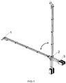
- FIG. 1 schematically illustrated embodiment.
- the FIG. 1 shows a chimney having two exhaust pipes 1, and a hinge 3 and a weight third
- the fireplace is attached to the truck via the swivel joint.
- the chimney is in a horizontal position.
- the top of the chimney, so at the exit of the exhaust pipes, may additionally be attached to the truck.
- the exhaust pipes are stabilized by a scaffolding construction. In the transport position, the exhaust system does not tower over the truck or hardly, so the exhaust system can in particular be laterally attached to a storage tank.
- the swivel joint can be moved at 90 ° so that the chimney can be set up.
- the weight 3 serves as a counterweight. It facilitates the erection of the fireplace and keeps it in position.
- the chimney is raised.
- the chimney tower s over the truck by at least 4 m.
- the example shown does not have a telescope system so that the length of the chimney can not be varied here. However, in other embodiments this is conceivable.
Landscapes
- Engineering & Computer Science (AREA)
- Mechanical Engineering (AREA)
- General Engineering & Computer Science (AREA)
- Filling Or Discharging Of Gas Storage Vessels (AREA)
Abstract
Description
- Die Erfindung betrifft ein Verfahren zur Ableitung von Abgasen an einer mobilen Anlage, zur Befüllung von Speicherbehältern mit Wasserstoff, sowie ein Abgassystem, welches zur Ableitung von Abgasen aus einer mobilen Anlage zur Befüllung von Speicherbehältern mit Wasserstoff eingerichtet ist.
- Wasserstofftankstellen, zur Befüllung von kleineren Speichertanks, insbesondere von Speichertanks in PKWs und Bussen, sind bisher kaum verbreitet. Wasserstoff der in Brennstoffzellen verbrannt wird, gilt jedoch als Kraftstoff der Zukunft. Immer mehr Autohersteller haben serienreife Wasserstofffahrzeuge im Angebot. Eine breite Markteinführung scheitert jedoch bisher auch an der geringen Verbreitung von Wasserstofftankstellen. Wasserstofftankstellen können bisher kaum wirtschaftlich betrieben werden, da es zu wenige Fahrzeuge gibt, die diesen Kraftstoff benötigen. Es ist deshalb notwendig, während der Markteinführung der wasserstoffbetriebenen Fahrzeuge Wasserstofftankstellen möglichst kostengünstig zu gestalten. Eine Möglichkeit sind hierfür mobile Tankstellen, die auf einem Lastwagen installiert sind. Eine weitere Variante sind festinstallierte Tankstellen bei denen jedoch nur die notwendigste Infrastruktur vorhanden ist. Nicht für den normalen Betankungsprozess notwendige Bestandteile, die mobil auf einem Lastwagen installiert sind könnten sich mehrere Tankstellen teilen.
- Bei der Befüllung von Speichertanks, insbesondere von fest installierten Speichertanks an Tankstellen oder von Speichertanks in mobilen Fahrzeugen fällt Abgas an. Auffangsysteme für dieses Abgas sind möglich, jedoch kostenintensiv. So ist es gerade für kleine Wasserstofftankstellen rentabler das Abgas in die Atmosphäre abzugeben, als Infrastruktur zur Aufarbeitung bereit zu stellen. Für Wasserstoff sind jedoch bei der Einleitung in die Atmosphäre besondere Vorkehrungen zu treffen. So muss das Gas insbesondere in einer bestimmten Höhe freigesetzt werden. Die notwendige Höhe ist abhängig von der Umgebung und den umgebenden Bedingungen, wie beispielsweise der Wetterlage. Die Ableitung in einer bestimmten Höhe ist bisher mit technischem und logistischem Aufwand verbunden, da mit Hilfe von Kränen oder mit Gerüsten, was Arbeiten in großer Höhe mit sich führt, ein Kamin installiert werden muss, über den das Abgas freigesetzt werden kann.
- Aufgabe der vorliegenden Erfindung ist es deshalb ein Verfahren und eine Vorrichtung anzugeben, bei dem das Abgas sicher und ohne großen Installationsaufwand in mindestens der gesetzlich vorgegebenen Höhe abgeleitet werden kann.
- Verfahrensseitig wird die Aufgabe dadurch gelöst, dass die Ableitung der Abgase in einer Höhe von 1 bis 12 m über einen an der mobilen Anlage beweglich angebrachten Kamin erfolgt. Vorrichtungsseitig wird die Aufgabe dadurch gelöst, dass das Abgassystem mindestens einen Kamin umfasst, an einer mobilen Anlage angebracht ist und ein Drehgelenk, mit welchem der Kamin horizontal oder vertikal installierbar ist.
- Unter horizontal oder vertikal ist jeweils auch eine Abweichung von der horizontalen Lage um bis zu + oder - 45 Grad, insbesondere um + oder - 5 bis 20 Grad zu verstehen.
- Bevorzugt wird der bewegliche Kamin direkt an der mobilen Anlage installiert. Die mobile Anlage kann entweder selbst als Tankstelle fungieren oder sie befüllt die Speicherbehälter einer festinstallierten Tankstelle. Als mobile Anlage wird insbesondere ein Lastwagen, welcher einen Speichertank zum Transport von Wasserstoff umfasst, verstanden.
- Als Abgas wird hier vor allem Wasserstoffgas bezeichnet, welches nicht im richtigen Temperatur oder Druckbereich vorliegt um für die Betankung oder Befüllung verwendet zu werden. Dies entsteht insbesondere durch Reste von Wasserstoff in den Leitungen oder durch Abdampfverluste, sogenanntes Boil-off gas, in den Speicherbehältern. Auch aus Sicherheitseinrichtungen wie Sicherheitsventilen, Überstömventilen oder der Not-Schnellentspannung des Leitungssystems kann Abgas anfallen. Abgas kann deshalb sowohl in der mobilen Anlage entstehen, im Speicherbehälter der Tankstelle oder dem anliefernden Lastwagen oder aber auch in den zu befüllenden Speicherbehältern. Bevorzugt sind deshalb Mittel vorgesehen das gesamte anfallende Abgas, also Wasserstoffabgas, über das Abgassystem mit dem Kamin abzuleiten.
- Das Abgassystem umfasst neben dem Kamin und dessen Befestigungsvorrichtungen auch die entsprechenden Leitungen oder Verbindungsstutzen zum Anschluss von Leitungen um das Wasserstoffabgas abführen zu können. Der Kamin selbst besteht aus einem oder aus mehreren Rohren in denen das Wasserstoffgas geführt wird und aus einem stabilisierendem Gerüst für das Rohr. Der Gasauslass der Rohre, also die Ausgangsöffnung, ist vorteilhafterweise so geformt, dass möglichst keine Verunreinigungen von außen, insbesondere Regenwasser, eindringen können und dass das Abgas leise und gleichmäßig abgeführt werden kann. So kann das Rohr am oder in der Nähe des Gasauslasses Rückschlagklappen enthalten. In einer bevorzugten Ausgestaltung ist das Rohr aus Edelstahl gefertigt und hat einen Innendurchmesser von 40 bis 50 mm sowie ein Länge von 6 m.
- Die Anschlüsse der Abgasleitung sind vorteilhafterweise möglichst nahe am Drehpunkt des Kamins angebracht. Bevorzugt ist der Kamin mit flexiblen Schläuchen verbunden, so dass die Bewegung des Kamins aufgenommen werden kann.
- Vorteilhafterweise wird der Kamin, während des Transports der mobilen Anlage, so montiert, dass der Kamin die Höhe der mobilen Anlage um maximal 1 bis 50 cm, insbesondere maximal 5 bis 20 cm überschreitet. In horizontaler Lage überragt das Abgassystem also die mobile Anlage um maximal 1 bis 50 cm, insbesondere maximal 5 bis 20 cm. Bevorzugt ist das Abgassystem jedoch so angebracht, dass die Gesamthöhe der mobilen Anlage dadurch nicht erhöht wird. Ist das Abgassystem beispielsweise an einem Lastwagen montiert, der einen Tank zum Transport von Wasserstoff besitzt, um fest installierte Speicherbehälter mit Wasserstoff zu beliefern, soll die Gesamthöhe und die Gesamtlänge des Lastwagens, also insbesondere des Anhängers des Lastwagens, nicht verändert werden.
- Während des Betriebes der mobilen Anlage wird der Kamin vorteilhafterweise auf eine Höhe von 1 bis 12 m, insbesondere von 2 bis 5 m und bevorzugt um 6 m ausgefahren. In vertikaler Lage überragt das Abgassystem also die mobile Anlage um 1 bis 12 m, insbesondere um 2 bis 5 m und bevorzugt um 6 m.
- Bevorzugterweise kann der Kamin über ein Drehgelenk so bewegt werden, dass er während des Transports horizontal ist und während des Betriebes vertikal. Zudem ist es vorteilhaft, wenn das Kaminrohr über ein Teleskopsystem verfügt, also verlängerbar ist, so dass er einfach und flexibel an die benötigte Höhe angepasst werden kann. Als Grundläge kann beispielsweise die Länge der mobilen Anlage, insbesondere eines Lastwagen Anhängers gewählt werden. Vorteilhafterweise verfügt der Kamin über eine Gegenmasse auf der einer Ausgangsöffnung des Kamins gegenüberliegenden Seite. Durch diese Gegenmasse oder Gegengewicht ist es für einen Bediener einfach möglich den Kamin aufzustellen oder einzuklappen. Das Drehgelenk selbst kann so ausgeführt sein, dass es in einer Position fixiert werden kann um die Lage des Kamins zu sichern. Zusätzlich können jedoch noch weitere Befestigungsvorrichtungen, wie Bolzen oder Klinken, vorgesehen sein. So kann insbesondere ein Befestigungsmechanismus vorgesehen sein um die Spitze des Kamins während des Transports bzw. in horizontaler Lage an der mobilen Anlage zu fixieren. Ebenso kann ein weiterer Befestigungsmechanismus vorgesehen sein um den Kamin in vertikaler Lage zu fixieren.
- In einer weiteren Ausgestaltungsvariante kann es hingegen vorteilhaft sein, wenn eine Feder vorgesehen ist um den Kamin zu fixieren. So kann an Stelle einer Gegenmasse, oder zur Unterstützung dieser, eine Feder vorgesehen sein um den Kamin in horizontaler oder vertikaler Lage zu fixieren. Die Federkraft erzeugt so die notwendige Kraft um den Kamin in Transport- oder Betriebsstellung zu befestigen. Die Federkraft kann auch unterstützend beim Aufrichten oder Einfahren des Kamins wirken.
- Zusätzlich zu diesen an der mobilen Anlage angebrachten Befestigungsvorrichtungen sind im Normalbetrieb keine weiteren Fixierungen vorgesehen. Es kann jedoch notwendig sein, insbesondere bei starken Winden, dass eine zusätzliche Fixierung des Kamins in vertikaler Position, insbesondere durch Seile notwendig ist.
- Wird in einem besonderen Ausführungsfall der Kamin nur für die Ableitung des Abgases aus einem Speichertank verwendet, kann die Zuführung des Abgases zum Kamin über flexible Schläuche dauerhaft installiert sein. So entfallen Verschraubungsarbeiten und Dichtheitsprüfungen vor der Inbetriebnahme. Der Zeitaufwand kann dadurch reduziert werden.
- Der beschriebene Kamin bietet Vorteile insbesondere bei der Befüllung von Speichertanks mit Wasserstoff. Er kann jedoch ebenso bei anderen Abgasen, insbesondere bei Abgasen von Erdgas verwendet werden. Insbesondere bei der Befüllung von Speichertanks mit flüssigem Erdgas oder Autogas fallen ebenfalls Boil-off Gase an, die an die Umgebung abgeleitet werden müssen.
- Bei der Verwendung eines erfindungsgemäßen Abgassystems entfallen Arbeiten in großen Höhen, somit auch die Bereitstellung der entsprechenden Arbeitsmittel und die Gewährung der Arbeitssicherheit. Für den Bediener der Anlage ist in der Regel keine Notwendigkeit für die aktive Verschraubung von Leitungen notwendig. Die Bedingung des Kamins kann von einer Person alleine ausgeführt werden.
- Im Folgenden soll die Erfindung anhand eines in der
Figur 1 schematisch dargestellten Ausführungsbeispiels näher erläutert werden. - Die
Figur 1 zeigt einen Kamin der über zwei Abgasrohre 1 verfügt, sowie ein Drehgelenk 3 und ein Gewicht 3.
Der Kamin ist über das Drehgelenk an einem Lastwagen befestigt. Während des Transportes oder wenn das Abgassystem nicht in Betrieb ist befindet sich der Kamin in horizontaler Lage. Die Spitze des Kamins, also am Ausgang der Abgasrohre, kann zusätzlich am Lastwagen befestigt sein. Die Abgasrohre werden durch eine Gerüstkonstruktion, stabilisiert.
In Transportposition überragt das Abgassystem den Lastwagen nicht oder kaum, so kann das Abgassystem insbesondere seitlich an einem Speichertank befestigt werden. Das Drehgelenk kann im 90° Winkel bewegt werden, so dass der Kamin aufgestellt werden kann. Das Gewicht 3 dient hierzu als Gegengewicht. Es erleichtert das Aufrichten des Kamins und hält diesen in Position.
Wird das Abgassystem benötigt, wird der Kamin aufgerichtet. Im dargestellten Beispiel überragt der Kamin den Lastwagen damit um mindestens 4 m.
Das dargestellte Beispiel verfügt nicht über ein Teleskopsystem so dass hier die Länge des Kamins nicht variiert werden kann. In anderen Ausführungsformen ist dies jedoch vorstellbar.
Claims (9)
- Verfahren zur Ableitung von Abgasen an einer mobilen Anlage, zur Befüllung von Speicherbehältern mit Wasserstoff, dadurch gekennzeichnet, dass die Ableitung der Abgase in einer Höhe von 1 bis 12 m über einen an der mobilen Anlage beweglich angebrachten Kamin erfolgt.
- Verfahren nach Anspruch 1, dadurch gekennzeichnet, dass der Kamin, während des Transports der mobilen Anlage, so montiert wird, dass der Kamin die Höhe der mobilen Anlage um maximal 1 bis 50 cm, insbesondere maximal 5 bis 20 cm überschreitet.
- Verfahren nach Anspruch 1, dadurch gekennzeichnet, dass der Kamin während des Betriebes der mobilen Anlage, auf eine Höhe von 1 bis 12 m, insbesondere von 2 bis 5 m ausgefahren wird.
- Verfahren nach mindestens einem der Ansprüche 1 bis 3, dadurch gekennzeichnet, dass der Kamin über ein Drehgelenk so bewegt werden kann, dass er während des Transports horizontal ist und während des Betriebes vertikal.
- Abgassystem zur Ableitung von Abgasen aus einer mobilen Anlage zur Befüllung von Speicherbehältern mit Wasserstoff, dadurch gekennzeichnet, dass das Abgassystem mindestens einen Kamin umfasst, an einer mobilen Anlage angebracht ist und ein Drehgelenk mit welchem der Kamin horizontal oder vertikal installierbar ist.
- Abgassystem nach Anspruch 5, dadurch gekennzeichnet, dass der Kamin über eine Gegenmasse auf der einer Ausgangsöffnung des Kamins gegenüberliegenden Seite verfügt.
- Abgassystem nach Anspruch 5, dadurch gekennzeichnet, dass eine Feder vorgesehen ist um den Kamin zu fixieren.
- Abgassystem nach mindestens einem der Ansprüche 5 bis 7, dadurch gekennzeichnet, dass das Abgassystem in horizontaler Lage, die mobile Anlage um maximal 1 bis 50 cm, insbesondere maximal 5 bis 20 cm überragt.
- Abgassystem nach mindestens einem der Ansprüche 5 bis 8, dadurch gekennzeichnet, dass das Abgassystem in vertikaler Lage, die mobile Anlage um 1 bis 12 m, insbesondere um 2 bis 5 m überragt.
Applications Claiming Priority (1)
| Application Number | Priority Date | Filing Date | Title |
|---|---|---|---|
| DE102015015529.6A DE102015015529A1 (de) | 2015-12-01 | 2015-12-01 | Abgassystem für mobile Wasserstofftransportsysteme |
Publications (2)
| Publication Number | Publication Date |
|---|---|
| EP3176491A1 true EP3176491A1 (de) | 2017-06-07 |
| EP3176491B1 EP3176491B1 (de) | 2020-12-02 |
Family
ID=57218658
Family Applications (1)
| Application Number | Title | Priority Date | Filing Date |
|---|---|---|---|
| EP16002188.7A Active EP3176491B1 (de) | 2015-12-01 | 2016-10-11 | Abgassystem für mobile wasserstofftransportsysteme |
Country Status (2)
| Country | Link |
|---|---|
| EP (1) | EP3176491B1 (de) |
| DE (1) | DE102015015529A1 (de) |
Citations (4)
| Publication number | Priority date | Publication date | Assignee | Title |
|---|---|---|---|---|
| GB2238732A (en) * | 1989-12-06 | 1991-06-12 | Nederman Philip & Co Ab | Waste-extraction unit |
| DE29506246U1 (de) * | 1994-04-12 | 1995-06-14 | Solvay Specialty Chemicals, Inc., Fairfield, N.J. | Vorrichtung zum Eindämmen und Waschen von toxischem Gas aus einer Leckstelle |
| US20100115896A1 (en) * | 2008-11-11 | 2010-05-13 | Reid James K | Portable air filtration system |
| US20130061983A1 (en) * | 2011-09-14 | 2013-03-14 | Toyota Jidosha Kabushiki Kaisha | Suction nozzle, suction device, gas filling device, gas consuming device and gas filling system |
-
2015
- 2015-12-01 DE DE102015015529.6A patent/DE102015015529A1/de not_active Withdrawn
-
2016
- 2016-10-11 EP EP16002188.7A patent/EP3176491B1/de active Active
Patent Citations (4)
| Publication number | Priority date | Publication date | Assignee | Title |
|---|---|---|---|---|
| GB2238732A (en) * | 1989-12-06 | 1991-06-12 | Nederman Philip & Co Ab | Waste-extraction unit |
| DE29506246U1 (de) * | 1994-04-12 | 1995-06-14 | Solvay Specialty Chemicals, Inc., Fairfield, N.J. | Vorrichtung zum Eindämmen und Waschen von toxischem Gas aus einer Leckstelle |
| US20100115896A1 (en) * | 2008-11-11 | 2010-05-13 | Reid James K | Portable air filtration system |
| US20130061983A1 (en) * | 2011-09-14 | 2013-03-14 | Toyota Jidosha Kabushiki Kaisha | Suction nozzle, suction device, gas filling device, gas consuming device and gas filling system |
Also Published As
| Publication number | Publication date |
|---|---|
| DE102015015529A1 (de) | 2017-06-01 |
| EP3176491B1 (de) | 2020-12-02 |
Similar Documents
| Publication | Publication Date | Title |
|---|---|---|
| AT523484A1 (de) | Verfahren und Penetriereinheit zum Einbringen eines Fluides in eine Batterie sowie damit ausgestattetes Fahrzeug | |
| EP2909524B1 (de) | Verfahren zum befüllen einer kraftstoffspeicheranlage eines kraftfahrzeugs | |
| AT525039B1 (de) | Wagen zur brandbekämpfung | |
| DE102019134744A1 (de) | Kraftfahrzeug mit einem Einspeiseanschluss für fahrzeugexternes Löschmittel | |
| DE102009039079A1 (de) | Tankanordnung | |
| WO2022049230A1 (de) | Druckbehälter, druckbehältersystem und kraftfahrzeug mit brennstoffleiste | |
| EP4151857A1 (de) | Vorrichtung zur lokalen inspektion und/oder reparatur und/oder beschichtung von rotorblättern einer windenergieanlage | |
| EP4078012A1 (de) | Verfahren zur betankung eines fahrzeugs | |
| WO2018134116A1 (de) | Druckbehältersystem für ein kraftfahrzeug | |
| DE2650903A1 (de) | Absperrventil fuer rohrleitungen grossen querschnitts | |
| EP3176491B1 (de) | Abgassystem für mobile wasserstofftransportsysteme | |
| DE102017208419A1 (de) | Betankungsanordnung eines Fahrzeugs | |
| DE102017209322A1 (de) | Brennstoffzellensystem mit einem Sollbruchteil zwischen dem Wasserstoff-Zufuhrventil und dem Wasserstoff-Absperrventil | |
| DE2409258A1 (de) | Verlader-fuelleinheit | |
| DE102012022621B4 (de) | Vorrichtung zum Aufwippen eines Kranauslegersystems | |
| EP4166199A1 (de) | Vorrichtung und verfahren zur passivierung eines brennenden fahrzeugs | |
| EP3951246A1 (de) | Füllwagen für eine mehrzahl von gasflaschen | |
| DE102009018867B4 (de) | Verschlusseinrichtung für Flanschrohre oder Flanschstutzen | |
| EP2811229B1 (de) | Transportable Anlage zur Verbrennung von unerwünschten Gasen | |
| EP3581794A1 (de) | Montagesystem und montageverfahren für einen rotorstern einer windenergieanlage | |
| DE102016221228A1 (de) | Wartungsinstrument für eine Windkraftanlage und Wartungsverfahren unter Verwendung des Wartungsinstruments | |
| DE102018115097A1 (de) | Verfahren zum Einfahren eines Stützbeins eines Fahrzeuges sowie hydropneumatisches System | |
| EP2703337A1 (de) | Sicherheitsvorrichtung für Kesselbetankung | |
| AT517045A2 (de) | Lagerbock zur Lagerung einer Rollenbatterie | |
| DE102015016319A1 (de) | Hochdruckleitung |
Legal Events
| Date | Code | Title | Description |
|---|---|---|---|
| AK | Designated contracting states |
Kind code of ref document: A1 Designated state(s): AL AT BE BG CH CY CZ DE DK EE ES FI FR GB GR HR HU IE IS IT LI LT LU LV MC MK MT NL NO PL PT RO RS SE SI SK SM TR |
|
| AX | Request for extension of the european patent |
Extension state: BA ME |
|
| PUAI | Public reference made under article 153(3) epc to a published international application that has entered the european phase |
Free format text: ORIGINAL CODE: 0009012 |
|
| STAA | Information on the status of an ep patent application or granted ep patent |
Free format text: STATUS: THE APPLICATION HAS BEEN PUBLISHED |
|
| STAA | Information on the status of an ep patent application or granted ep patent |
Free format text: STATUS: REQUEST FOR EXAMINATION WAS MADE |
|
| 17P | Request for examination filed |
Effective date: 20171206 |
|
| RBV | Designated contracting states (corrected) |
Designated state(s): AL AT BE BG CH CY CZ DE DK EE ES FI FR GB GR HR HU IE IS IT LI LT LU LV MC MK MT NL NO PL PT RO RS SE SI SK SM TR |
|
| STAA | Information on the status of an ep patent application or granted ep patent |
Free format text: STATUS: EXAMINATION IS IN PROGRESS |
|
| 17Q | First examination report despatched |
Effective date: 20190521 |
|
| GRAP | Despatch of communication of intention to grant a patent |
Free format text: ORIGINAL CODE: EPIDOSNIGR1 |
|
| STAA | Information on the status of an ep patent application or granted ep patent |
Free format text: STATUS: GRANT OF PATENT IS INTENDED |
|
| RAP1 | Party data changed (applicant data changed or rights of an application transferred) |
Owner name: LINDE GMBH |
|
| INTG | Intention to grant announced |
Effective date: 20200603 |
|
| GRAS | Grant fee paid |
Free format text: ORIGINAL CODE: EPIDOSNIGR3 |
|
| GRAA | (expected) grant |
Free format text: ORIGINAL CODE: 0009210 |
|
| STAA | Information on the status of an ep patent application or granted ep patent |
Free format text: STATUS: THE PATENT HAS BEEN GRANTED |
|
| AK | Designated contracting states |
Kind code of ref document: B1 Designated state(s): AL AT BE BG CH CY CZ DE DK EE ES FI FR GB GR HR HU IE IS IT LI LT LU LV MC MK MT NL NO PL PT RO RS SE SI SK SM TR |
|
| REG | Reference to a national code |
Ref country code: GB Ref legal event code: FG4D Free format text: NOT ENGLISH |
|
| REG | Reference to a national code |
Ref country code: AT Ref legal event code: REF Ref document number: 1341310 Country of ref document: AT Kind code of ref document: T Effective date: 20201215 Ref country code: CH Ref legal event code: EP |
|
| REG | Reference to a national code |
Ref country code: IE Ref legal event code: FG4D Free format text: LANGUAGE OF EP DOCUMENT: GERMAN |
|
| REG | Reference to a national code |
Ref country code: DE Ref legal event code: R096 Ref document number: 502016011814 Country of ref document: DE |
|
| PG25 | Lapsed in a contracting state [announced via postgrant information from national office to epo] |
Ref country code: NO Free format text: LAPSE BECAUSE OF FAILURE TO SUBMIT A TRANSLATION OF THE DESCRIPTION OR TO PAY THE FEE WITHIN THE PRESCRIBED TIME-LIMIT Effective date: 20210302 Ref country code: RS Free format text: LAPSE BECAUSE OF FAILURE TO SUBMIT A TRANSLATION OF THE DESCRIPTION OR TO PAY THE FEE WITHIN THE PRESCRIBED TIME-LIMIT Effective date: 20201202 Ref country code: FI Free format text: LAPSE BECAUSE OF FAILURE TO SUBMIT A TRANSLATION OF THE DESCRIPTION OR TO PAY THE FEE WITHIN THE PRESCRIBED TIME-LIMIT Effective date: 20201202 Ref country code: GR Free format text: LAPSE BECAUSE OF FAILURE TO SUBMIT A TRANSLATION OF THE DESCRIPTION OR TO PAY THE FEE WITHIN THE PRESCRIBED TIME-LIMIT Effective date: 20210303 |
|
| REG | Reference to a national code |
Ref country code: NL Ref legal event code: MP Effective date: 20201202 |
|
| PG25 | Lapsed in a contracting state [announced via postgrant information from national office to epo] |
Ref country code: BG Free format text: LAPSE BECAUSE OF FAILURE TO SUBMIT A TRANSLATION OF THE DESCRIPTION OR TO PAY THE FEE WITHIN THE PRESCRIBED TIME-LIMIT Effective date: 20210302 Ref country code: LV Free format text: LAPSE BECAUSE OF FAILURE TO SUBMIT A TRANSLATION OF THE DESCRIPTION OR TO PAY THE FEE WITHIN THE PRESCRIBED TIME-LIMIT Effective date: 20201202 Ref country code: SE Free format text: LAPSE BECAUSE OF FAILURE TO SUBMIT A TRANSLATION OF THE DESCRIPTION OR TO PAY THE FEE WITHIN THE PRESCRIBED TIME-LIMIT Effective date: 20201202 Ref country code: PL Free format text: LAPSE BECAUSE OF FAILURE TO SUBMIT A TRANSLATION OF THE DESCRIPTION OR TO PAY THE FEE WITHIN THE PRESCRIBED TIME-LIMIT Effective date: 20201202 |
|
| PG25 | Lapsed in a contracting state [announced via postgrant information from national office to epo] |
Ref country code: NL Free format text: LAPSE BECAUSE OF FAILURE TO SUBMIT A TRANSLATION OF THE DESCRIPTION OR TO PAY THE FEE WITHIN THE PRESCRIBED TIME-LIMIT Effective date: 20201202 Ref country code: HR Free format text: LAPSE BECAUSE OF FAILURE TO SUBMIT A TRANSLATION OF THE DESCRIPTION OR TO PAY THE FEE WITHIN THE PRESCRIBED TIME-LIMIT Effective date: 20201202 |
|
| REG | Reference to a national code |
Ref country code: LT Ref legal event code: MG9D |
|
| PG25 | Lapsed in a contracting state [announced via postgrant information from national office to epo] |
Ref country code: PT Free format text: LAPSE BECAUSE OF FAILURE TO SUBMIT A TRANSLATION OF THE DESCRIPTION OR TO PAY THE FEE WITHIN THE PRESCRIBED TIME-LIMIT Effective date: 20210405 Ref country code: SK Free format text: LAPSE BECAUSE OF FAILURE TO SUBMIT A TRANSLATION OF THE DESCRIPTION OR TO PAY THE FEE WITHIN THE PRESCRIBED TIME-LIMIT Effective date: 20201202 Ref country code: RO Free format text: LAPSE BECAUSE OF FAILURE TO SUBMIT A TRANSLATION OF THE DESCRIPTION OR TO PAY THE FEE WITHIN THE PRESCRIBED TIME-LIMIT Effective date: 20201202 Ref country code: EE Free format text: LAPSE BECAUSE OF FAILURE TO SUBMIT A TRANSLATION OF THE DESCRIPTION OR TO PAY THE FEE WITHIN THE PRESCRIBED TIME-LIMIT Effective date: 20201202 Ref country code: CZ Free format text: LAPSE BECAUSE OF FAILURE TO SUBMIT A TRANSLATION OF THE DESCRIPTION OR TO PAY THE FEE WITHIN THE PRESCRIBED TIME-LIMIT Effective date: 20201202 Ref country code: SM Free format text: LAPSE BECAUSE OF FAILURE TO SUBMIT A TRANSLATION OF THE DESCRIPTION OR TO PAY THE FEE WITHIN THE PRESCRIBED TIME-LIMIT Effective date: 20201202 Ref country code: LT Free format text: LAPSE BECAUSE OF FAILURE TO SUBMIT A TRANSLATION OF THE DESCRIPTION OR TO PAY THE FEE WITHIN THE PRESCRIBED TIME-LIMIT Effective date: 20201202 |
|
| REG | Reference to a national code |
Ref country code: DE Ref legal event code: R097 Ref document number: 502016011814 Country of ref document: DE |
|
| PG25 | Lapsed in a contracting state [announced via postgrant information from national office to epo] |
Ref country code: IS Free format text: LAPSE BECAUSE OF FAILURE TO SUBMIT A TRANSLATION OF THE DESCRIPTION OR TO PAY THE FEE WITHIN THE PRESCRIBED TIME-LIMIT Effective date: 20210402 |
|
| PLBE | No opposition filed within time limit |
Free format text: ORIGINAL CODE: 0009261 |
|
| STAA | Information on the status of an ep patent application or granted ep patent |
Free format text: STATUS: NO OPPOSITION FILED WITHIN TIME LIMIT |
|
| PG25 | Lapsed in a contracting state [announced via postgrant information from national office to epo] |
Ref country code: IT Free format text: LAPSE BECAUSE OF FAILURE TO SUBMIT A TRANSLATION OF THE DESCRIPTION OR TO PAY THE FEE WITHIN THE PRESCRIBED TIME-LIMIT Effective date: 20201202 Ref country code: AL Free format text: LAPSE BECAUSE OF FAILURE TO SUBMIT A TRANSLATION OF THE DESCRIPTION OR TO PAY THE FEE WITHIN THE PRESCRIBED TIME-LIMIT Effective date: 20201202 |
|
| 26N | No opposition filed |
Effective date: 20210903 |
|
| PG25 | Lapsed in a contracting state [announced via postgrant information from national office to epo] |
Ref country code: DK Free format text: LAPSE BECAUSE OF FAILURE TO SUBMIT A TRANSLATION OF THE DESCRIPTION OR TO PAY THE FEE WITHIN THE PRESCRIBED TIME-LIMIT Effective date: 20201202 Ref country code: SI Free format text: LAPSE BECAUSE OF FAILURE TO SUBMIT A TRANSLATION OF THE DESCRIPTION OR TO PAY THE FEE WITHIN THE PRESCRIBED TIME-LIMIT Effective date: 20201202 |
|
| PG25 | Lapsed in a contracting state [announced via postgrant information from national office to epo] |
Ref country code: ES Free format text: LAPSE BECAUSE OF FAILURE TO SUBMIT A TRANSLATION OF THE DESCRIPTION OR TO PAY THE FEE WITHIN THE PRESCRIBED TIME-LIMIT Effective date: 20201202 |
|
| PG25 | Lapsed in a contracting state [announced via postgrant information from national office to epo] |
Ref country code: IS Free format text: LAPSE BECAUSE OF FAILURE TO SUBMIT A TRANSLATION OF THE DESCRIPTION OR TO PAY THE FEE WITHIN THE PRESCRIBED TIME-LIMIT Effective date: 20210402 |
|
| REG | Reference to a national code |
Ref country code: BE Ref legal event code: MM Effective date: 20211031 |
|
| GBPC | Gb: european patent ceased through non-payment of renewal fee |
Effective date: 20211011 |
|
| PG25 | Lapsed in a contracting state [announced via postgrant information from national office to epo] |
Ref country code: MC Free format text: LAPSE BECAUSE OF FAILURE TO SUBMIT A TRANSLATION OF THE DESCRIPTION OR TO PAY THE FEE WITHIN THE PRESCRIBED TIME-LIMIT Effective date: 20201202 |
|
| PG25 | Lapsed in a contracting state [announced via postgrant information from national office to epo] |
Ref country code: LU Free format text: LAPSE BECAUSE OF NON-PAYMENT OF DUE FEES Effective date: 20211011 Ref country code: GB Free format text: LAPSE BECAUSE OF NON-PAYMENT OF DUE FEES Effective date: 20211011 Ref country code: BE Free format text: LAPSE BECAUSE OF NON-PAYMENT OF DUE FEES Effective date: 20211031 |
|
| PG25 | Lapsed in a contracting state [announced via postgrant information from national office to epo] |
Ref country code: IE Free format text: LAPSE BECAUSE OF NON-PAYMENT OF DUE FEES Effective date: 20211011 |
|
| PG25 | Lapsed in a contracting state [announced via postgrant information from national office to epo] |
Ref country code: HU Free format text: LAPSE BECAUSE OF FAILURE TO SUBMIT A TRANSLATION OF THE DESCRIPTION OR TO PAY THE FEE WITHIN THE PRESCRIBED TIME-LIMIT; INVALID AB INITIO Effective date: 20161011 |
|
| PG25 | Lapsed in a contracting state [announced via postgrant information from national office to epo] |
Ref country code: CY Free format text: LAPSE BECAUSE OF FAILURE TO SUBMIT A TRANSLATION OF THE DESCRIPTION OR TO PAY THE FEE WITHIN THE PRESCRIBED TIME-LIMIT Effective date: 20201202 |
|
| PGFP | Annual fee paid to national office [announced via postgrant information from national office to epo] |
Ref country code: FR Payment date: 20231023 Year of fee payment: 8 Ref country code: DE Payment date: 20231018 Year of fee payment: 8 Ref country code: CH Payment date: 20231102 Year of fee payment: 8 Ref country code: AT Payment date: 20231019 Year of fee payment: 8 |
|
| PG25 | Lapsed in a contracting state [announced via postgrant information from national office to epo] |
Ref country code: MK Free format text: LAPSE BECAUSE OF FAILURE TO SUBMIT A TRANSLATION OF THE DESCRIPTION OR TO PAY THE FEE WITHIN THE PRESCRIBED TIME-LIMIT Effective date: 20201202 |
|
| PG25 | Lapsed in a contracting state [announced via postgrant information from national office to epo] |
Ref country code: TR Free format text: LAPSE BECAUSE OF FAILURE TO SUBMIT A TRANSLATION OF THE DESCRIPTION OR TO PAY THE FEE WITHIN THE PRESCRIBED TIME-LIMIT Effective date: 20201202 |
|
| PG25 | Lapsed in a contracting state [announced via postgrant information from national office to epo] |
Ref country code: MT Free format text: LAPSE BECAUSE OF FAILURE TO SUBMIT A TRANSLATION OF THE DESCRIPTION OR TO PAY THE FEE WITHIN THE PRESCRIBED TIME-LIMIT Effective date: 20201202 |
|
| REG | Reference to a national code |
Ref country code: DE Ref legal event code: R119 Ref document number: 502016011814 Country of ref document: DE |
|
| REG | Reference to a national code |
Ref country code: CH Ref legal event code: PL |
|
| REG | Reference to a national code |
Ref country code: AT Ref legal event code: MM01 Ref document number: 1341310 Country of ref document: AT Kind code of ref document: T Effective date: 20241011 |
|
| PG25 | Lapsed in a contracting state [announced via postgrant information from national office to epo] |
Ref country code: DE Free format text: LAPSE BECAUSE OF NON-PAYMENT OF DUE FEES Effective date: 20250501 |
|
| PG25 | Lapsed in a contracting state [announced via postgrant information from national office to epo] |
Ref country code: FR Free format text: LAPSE BECAUSE OF NON-PAYMENT OF DUE FEES Effective date: 20241031 |
|
| PG25 | Lapsed in a contracting state [announced via postgrant information from national office to epo] |
Ref country code: CH Free format text: LAPSE BECAUSE OF NON-PAYMENT OF DUE FEES Effective date: 20241031 |
|
| PG25 | Lapsed in a contracting state [announced via postgrant information from national office to epo] |
Ref country code: AT Free format text: LAPSE BECAUSE OF NON-PAYMENT OF DUE FEES Effective date: 20241011 |