EP3176448A1 - Connecting element - Google Patents
Connecting element Download PDFInfo
- Publication number
- EP3176448A1 EP3176448A1 EP15197461.5A EP15197461A EP3176448A1 EP 3176448 A1 EP3176448 A1 EP 3176448A1 EP 15197461 A EP15197461 A EP 15197461A EP 3176448 A1 EP3176448 A1 EP 3176448A1
- Authority
- EP
- European Patent Office
- Prior art keywords
- sleeve
- connecting element
- head
- element according
- shaft
- Prior art date
- Legal status (The legal status is an assumption and is not a legal conclusion. Google has not performed a legal analysis and makes no representation as to the accuracy of the status listed.)
- Granted
Links
- 238000007789 sealing Methods 0.000 claims abstract description 19
- 239000013536 elastomeric material Substances 0.000 claims abstract description 10
- 239000000463 material Substances 0.000 description 9
- 239000002184 metal Substances 0.000 description 6
- 230000000149 penetrating effect Effects 0.000 description 3
- 230000035515 penetration Effects 0.000 description 3
- 238000010276 construction Methods 0.000 description 1
- 238000003780 insertion Methods 0.000 description 1
- 230000037431 insertion Effects 0.000 description 1
- 238000009434 installation Methods 0.000 description 1
- 230000000284 resting effect Effects 0.000 description 1
- 239000002023 wood Substances 0.000 description 1
Images


Classifications
-
- F—MECHANICAL ENGINEERING; LIGHTING; HEATING; WEAPONS; BLASTING
- F16—ENGINEERING ELEMENTS AND UNITS; GENERAL MEASURES FOR PRODUCING AND MAINTAINING EFFECTIVE FUNCTIONING OF MACHINES OR INSTALLATIONS; THERMAL INSULATION IN GENERAL
- F16B—DEVICES FOR FASTENING OR SECURING CONSTRUCTIONAL ELEMENTS OR MACHINE PARTS TOGETHER, e.g. NAILS, BOLTS, CIRCLIPS, CLAMPS, CLIPS OR WEDGES; JOINTS OR JOINTING
- F16B43/00—Washers or equivalent devices; Other devices for supporting bolt-heads or nuts
- F16B43/001—Washers or equivalent devices; Other devices for supporting bolt-heads or nuts for sealing or insulation
-
- F—MECHANICAL ENGINEERING; LIGHTING; HEATING; WEAPONS; BLASTING
- F16—ENGINEERING ELEMENTS AND UNITS; GENERAL MEASURES FOR PRODUCING AND MAINTAINING EFFECTIVE FUNCTIONING OF MACHINES OR INSTALLATIONS; THERMAL INSULATION IN GENERAL
- F16B—DEVICES FOR FASTENING OR SECURING CONSTRUCTIONAL ELEMENTS OR MACHINE PARTS TOGETHER, e.g. NAILS, BOLTS, CIRCLIPS, CLAMPS, CLIPS OR WEDGES; JOINTS OR JOINTING
- F16B19/00—Bolts without screw-thread; Pins, including deformable elements; Rivets
- F16B19/02—Bolts or sleeves for positioning of machine parts, e.g. notched taper pins, fitting pins, sleeves, eccentric positioning rings
Definitions
- the invention relates to a connecting element, for the sealed connection and attachment of objects, consisting of a pin-shaped connecting means, with a shaft and a head, and arranged on the shaft sealing means.
- screws are known in the art as fasteners with a arranged on the screw shaft diameter-sized metal disc and a diameter-large sealing disc.
- the metal disc is arranged between the screw head and the sealing disc.
- the screw is inserted through a perforation of a roof panel and screwed into the wooden substructure.
- the screw head exerts pressure on the metal disc, which thus firmly presses the sealing disc onto the roof plate in the area of the perforation and the plate area surrounding the perforation and thus prevents moisture from entering the hole.
- the sealing takes place exclusively between the sealing washer and the roof panel.
- the metal disk and the sealing disk must have a larger diameter than the perforation so that they rest in a plate area surrounding the perforation and provide a seal in this area.
- Such screws are used for example for fastening roof or facade panels.
- Uneven holes in which, for example, the edge area of the hole is broken or uneven or breaks out during screwing in can not be securely sealed.
- the sealing disc may no longer cover the entire perforation and may no longer lie flat on the plate and the edge area of the hole, so that the sealing disc is not pressed evenly. Moisture can then penetrate through gaps between the sealing disc and the support surface.
- connecting means used to attach parts or to connect parts with wooden objects, such as for attaching roof panels to roof battens, it happens that the wooden structures dwindle and the The contact pressure of the screw wears off so that the sealing washer is not pressed sufficiently tightly onto the contact surface after some time and allows the penetration of moisture.
- the invention is based on the object to provide a durable connecting element with flat in mounting target position structure that is suitable for a secure, durable and cost-effective sealing of holes of connecting or fastening parts, even with uneven perforated walls and uneven edge areas to ensure.
- the sealing means is a sleeve of elastomeric material, which has a cylindrical through-channel, which is penetrated by the shaft, that the sleeve over its length has different wall thickness, namely at the ends of a smaller wall thickness than in the area between their ends.
- a hole for example by penetrating the shank of the connecting means, such as a screw or a nail, or holes are already prefabricated in the object to be fastened, through which the shaft of Lanyard can be plugged.
- the connecting means penetrates first with its tip and subsequently with the shaft in the object or the perforation.
- the first penetrating end of the sleeve has a smaller wall thickness than the region between its ends, whereby the penetration of the sleeve is facilitated in the hole.
- the sleeve is pressed during the driving of the shaft by the pressure of the head on the head near end partially, for example, up to half their length in the hole, the sleeve is supported with the area between their ends in the mouth region of the hole and at the hole reveal and the elastomeric material is compressed and pressed firmly against the soffit of the hole and thus securely seals the hole.
- the sleeve is stuck with the region of greater wall thickness in the hole, while the other area, in particular the near-end of the sleeve, protrudes from the hole and deformed by the pressure of the head when driving the connecting means and everted toward the head, so that the inverted end with the head in Final assembly position is positioned next to the mouth of the hole and rests on the plate material next to the perforation and thus closes the hole area.
- the small wall thickness of the sleeve at the head end facilitates the eversion of this sleeve area.
- a connecting element which not only covers and closes the upper side of the mouth of the hole, but also seals with the stuck in the hole thicker portion of the sleeve within the hole.
- the elastomeric material also permits the sealing of non-uniform openings whose marginal areas have broken away, wherein the thicker portion of the elastomeric sleeve inserted into the hole also conforms to a broken hole wall or cavity and fills out and securely seals off broken areas.
- a temperature or weather-related shrinkage of the wood material leads to a reduced contact pressure of the screw, but is seated by the sitting in the hole elastomeric material further secures the seal within the hole in the hole reveal, so that no moisture can penetrate into the hole.
- connecting element can be preassembled on pre-punched fastening means, such as clamps, for example roof clips or ridge clamps.
- the elastomeric sleeve can be inserted through the hole of the fastener with the connecting means and the connecting means is held captive between the thickened portion of the sleeve on the one hand and the head of the connecting means on the other hand.
- the pin-shaped connecting means is a nail.
- Connection means such as nails are used, for example, when roof panels are to be fastened to the wooden substructure of a roof.
- the roof panel preferably has a prefabricated hole through which the nail is inserted with the sleeve end.
- the pre-assembly of the nails together with sleeves is also conceivable for prefabricated holes.
- the nails together with sleeves can be inserted into holes in the roof panel and pressed so that they are held captive in the hole. When fixing the roof plate to the wooden substructure, the nails can then be driven into the wooden substructure.
- the pin-shaped connecting means is a screw.
- a screw is advantageous, for example, for fixing a roof plate on the wooden battens, wherein the roof plate has a prefabricated hole through which the screw is performed and in which the sleeve is inserted with its end.
- the screw in the region near the head has a non-threaded part or region and indeed in a length which is equal to or greater than the sleeve length.
- the sleeve While the screw penetrates more and more into the material until reaching the end position, the sleeve penetrates only partially into the hole, until it sits with the region of greater wall thickness between the ends in the hole. It is advantageous that the sleeve sits on the smooth, threadless part of the screw, since the screw remains independent of the sleeve rotatable and can be screwed into the end position, wherein the sleeve remains in position and not or only slightly rotates on the non-threaded portion ,
- the sleeve should penetrate evenly into the hole and sit snugly in the hole at the hole reveal.
- the non-threaded part ensures that the sleeve does not rotate on the thread and is twisted unevenly and is thus pressed into the hole.
- the thread of the screw projecting beyond the threadless portion and at least the thread adjacent to the lower wall thickness provided end of the sleeve or the head adjacent the end of the sleeve has such a wall thickness that the outer shell of the sleeve end with aligned with the thread.
- the thread specifies the size of the perforation, which is so large due to the aligned lateral surface that the end of the sleeve slides without much pressure in the hole until the wall thickness of the sleeve thickened and the sleeve gets stuck. If necessary, the sleeve penetrates even deeper into the hole, whereby the pressure exerted by the head continues to act on the head near the end and overturns it. If the outer jacket of the end adjacent to the head also escapes with the thread, the material thickness is sufficiently lower, so that the end can be optimally everted when screwed in.
- the cylindrical passageway of the sleeve which sits on the non-threaded portion of the screw, has a smaller inner diameter than the screw in the threaded portion. This allows the pre-assembly of the sleeve on the screw. For this purpose, the sleeve can be pushed over the thread due to the elastomeric material with little effort until it sits on the threadless part. Since the passage of the sleeve in such a configuration has a smaller inner diameter than the screw in the threaded portion, the sleeve is stopped by the thread and is held captive between the head and the beginning of the thread.
- the sleeve is crowned in longitudinal section.
- the sleeve is trapezoidal.
- the sleeve is elliptical in longitudinal section or forms a longitudinal section of a double cone tapering towards the ends.
- the sleeve is thickened in a longitudinal section from the ends to the region between the ends, wherein it is preferably provided that at least one step has a rounded or bevelled edge.
- the sleeve is arranged with play on the shaft.
- the sleeve moves during assembly on the shaft towards the head, where it deforms and inverts at the bottom of the head.
- the connecting means is a screw
- the diameter of the passageway of the sleeve is to be chosen so that the sleeve sits loosely on the shaft. This ensures that the sleeve can be supported on the inner wall of a hole and the sleeve is not pulled into the hole by the thread of the screw.
- the head has radially outwardly peripherally an edge projecting towards the shaft.
- the underside of the head has a circumferential groove or groove.
- the head is optionally formed in the manner of a lens head or a countersunk head.
- the lens head leads to only a slight projection in the assembly target position.
- the countersunk head is suitable for connections or fastenings in which a substantially flush arrangement to the perforated object or to its top is required.
- the head has an engagement contour for a screwing tool on its end face facing away from the shaft.
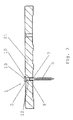
- Fig. 1 shows a variant of the connecting element 1 according to the invention in longitudinal section, namely a pin-shaped connecting means 2 and a sleeve 3 made of elastomeric material having a cylindrical passage 4, which is penetrated by the shaft 5 of the connecting means 2.
- the pin-shaped connecting means 2 is a screw with thread 6, wherein the sleeve 3 sits with play on a non-threaded, smooth part 7 of the shaft 5, which has a length which corresponds approximately to the sleeve length and between a head 13 and the beginning of the thread 6 is formed.
- Both ends 9, 10 of the sleeve 3 have such a compared to the area between the ends 11 tapered wall thickness, that the outer surface of the ends 9, 10 is aligned with the thread 6. This results in the advantage that the sleeve 3, as in Fig. 2 shown, with the adjacent to the thread 6 end 9 can more easily dive into a hole 8 of a part to be fastened, for example a roof panel 21.
- the cylindrical passage 4 of the sleeve 3 which sits on the unthreaded part 7 of the screw, has a smaller inner diameter than the screw in the region of the thread. This allows the pre-assembly of the sleeve 3 on the screw.
- the sleeve 3 can be pushed due to the elasticity of the elastomeric material with little effort on the thread 6 on the unthreaded part 7 of the shaft 5, where it is then held due to the smaller inner diameter of the passage 4 with respect to the screw through the thread 6 in the axial direction and held captive between the head 13 and thread 6.
- the outer surface of the near-head end 10 of the sleeve 3 is aligned with the thread 6, whereby a sufficiently small material thickness is present, so that the end 10 can evert when screwing, as in Fig. 4 is illustrated.
- Fig. 2 shows the connecting element 1 in Vormontagelage.
- the shank 5 of the connecting means 2 is partially inserted into a prefabricated hole 8 of the roof plate 21, and the thread 6 adjacent end 9 of the sleeve 3 is located immediately in front of the mouth of the hole. 8
- the sleeve 3 has different wall thickness over its length, namely at the ends 9, 10 a smaller wall thickness than in the region between the ends 11, so that it has a spherical shape in longitudinal section.
- This form is suitable It makes possible by their slender ends 9, 10 a slight sliding of the one end 9 of the sleeve 3 in the hole 8 and a good Stülpmix the near-head 10 end.
- the thickened area between the ends 11 fills the hole 8 in the final assembly position, such as Fig. 3 shows fully up to the soffit 12, wherein the elastomeric material is conformable and also allows complete lining of, for example, broken holes.
- the screw penetrates until reaching the final assembly position, Fig. 3 , more and more into the material, for example a roof plate, while at the same time the sleeve 3 is pressed by the pressure of the head 13 on the sleeve 3 in the hole 8 until the sleeve 3 with the area between the ends 11 in the soffit 12 of Hole 8 is seated, elastically supported on the soffit 12 radially and there is compressed by the pressure. Then the sleeve 3 sits firmly in the reveal 12 of the hole 8. The not penetrating into the hole 8 part of the sleeve 3 is deformed by the pressure of the head 13 and everted by the head 13 to the outside in the manner of a screen, Fig. 3 . 4 , The sleeve 3 can move independently of the movement of the screw parallel to the shaft 5 on the unthreaded part 7 and does not or only slightly participates in the rotational movement of the screw.
- a connecting element 1 is provided, which not only covers the mouth of a hole 8, but also ensures, with the plugged into the hole 8 end 9 of the sleeve 3, within the hole 8 a seal.
- Fig. 5 shows the connecting element 1 in a preassembled state on a fastening means, for example a clamp 15, for example a ridge clip.
- a fastening means for example a clamp 15, for example a ridge clip.
- the elastomeric sleeve 3 can be pushed together with the connecting means through the perforation 16, here a slot, the bracket 15 and is held captive by its thicker portion 11 between the thin ends 9,10 on the one hand and the head 13 on the other hand.
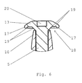
- Fig. 6 shows the detail B of the Fig. 1 , namely, the head 13 of the connecting means 2. This has radially outside a projecting towards the shaft 5 edge 17 on.
- the sleeve 3 when screwed in with the thicker region 11, reaches the hole 8 between the ends 9, 10, the sleeve 3 shifts on the shaft 5 in the axial direction to the shaft 5 until it abuts the underside 18 of the head 13.
- the head near end 10 is guided in the direction of the protruding edge 17 and everted by the edge 17 in the direction of the hole 8. This ensures that an optimal sealing takes place on the upper side next to the hole mouth and radially on the reveal 12.
- the head 13 is formed in the manner of a lens head. Depending on the application, different shapes of the head are possible.
- the head 13 also has, on its upper side facing away from the shaft 5, an engagement contour 20 for a screwing tool. As a result, a simple attachment and connection with a corresponding tool is possible.
Abstract
Die Erfindung betrifft ein Verbindungselement (1) zur abgedichteten Verbindung und Befestigung von Gegenständen, bestehend aus einem stiftförmigen Verbindungsmittel (2) mit einem Schaft (5) und einem Kopf (13) und einem auf dem Schaft (5) angeordneten Dichtungsmittel, wobei das Dichtungsmittel eine Hülse (3) aus elastomerem Material ist, die einen zylindrischen Durchgangskanal (4) aufweist, der vom Schaft (5) durchgriffen ist, und die Hülse (3) über ihre Länge unterschiedliche Wandstärke aufweist, nämlich an den Enden (9, 10) eine geringere Wandstärke als im Bereich (11) zwischen ihren Enden.The invention relates to a connecting element (1) for the sealed connection and fastening of objects, consisting of a pin-shaped connecting means (2) with a shaft (5) and a head (13) and a sealing means arranged on the shaft (5), wherein the sealing means a sleeve (3) of elastomeric material having a cylindrical passage (4) which is penetrated by the shaft (5), and the sleeve (3) over its length has different wall thickness, namely at the ends (9, 10) a smaller wall thickness than in the region (11) between their ends.
Description
Die Erfindung betrifft ein Verbindungselement, zur abgedichteten Verbindung und Befestigung von Gegenständen, bestehend aus einem stiftförmigen Verbindungsmittel, mit einem Schaft und einem Kopf, und einem auf dem Schaft angeordneten Dichtungsmittel.The invention relates to a connecting element, for the sealed connection and attachment of objects, consisting of a pin-shaped connecting means, with a shaft and a head, and arranged on the shaft sealing means.
Um Gegenstände abgedichtet zu verbinden oder zu befestigen, insbesondere im Arbeitsgebiet des Dachdeckerhandwerks, sind im Stand der Technik als Verbindungselemente Schrauben mit einer auf dem Schraubenschaft angeordneten durchmessergroßen Metallscheibe und einer durchmessergroßen Dichtscheibe bekannt. Die Metallscheibe ist zwischen dem Schraubenkopf und der Dichtscheibe angeordnet. Zum Verbinden oder Befestigen, beispielsweise von Dachplatten an einer Holzunterkonstruktion, wird die Schraube durch eine Lochung einer Dachplatte gesteckt und in die Holzunterkonstruktion eingeschraubt. Beim Anziehen der Schraube übt der Schraubenkopf Druck auf die Metallscheibe aus, welche somit die Dichtscheibe fest auf die Dachplatte im Bereich der Lochung und den die Lochung umgebenden Plattenbereich presst und so einen Feuchtigkeitseintritt in das Loch verhindert. Die Abdichtung erfolgt dabei ausschließlich zwischen Dichtscheibe und Dachplatte. Die Metallscheibe und die Dichtscheibe müssen einen gegenüber der Lochung größeren Durchmesser aufweisen, damit diese in einem die Lochung umgebenden Plattenbereich aufliegen und in diesem Bereich für eine Abdichtung sorgen.
Solche Schrauben werden beispielsweise zur Befestigung von Dach- oder Fassadenplatten eingesetzt.In order to connect or fix objects sealed, in particular in the field of roofing craft, screws are known in the art as fasteners with a arranged on the screw shaft diameter-sized metal disc and a diameter-large sealing disc. The metal disc is arranged between the screw head and the sealing disc. To connect or attach, for example, roof panels to a wooden substructure, the screw is inserted through a perforation of a roof panel and screwed into the wooden substructure. At the Tightening the screw, the screw head exerts pressure on the metal disc, which thus firmly presses the sealing disc onto the roof plate in the area of the perforation and the plate area surrounding the perforation and thus prevents moisture from entering the hole. The sealing takes place exclusively between the sealing washer and the roof panel. The metal disk and the sealing disk must have a larger diameter than the perforation so that they rest in a plate area surrounding the perforation and provide a seal in this area.
Such screws are used for example for fastening roof or facade panels.
Ungleichmäßige Löcher, bei denen beispielsweise der Randbereich des Loches ausgebrochen oder uneben ist oder während des Einschraubens ausbricht, können nicht sicher abgedichtet werden. Die Dichtscheibe deckt in diesem Fall möglicherweise nicht mehr die gesamte Lochung ab und liegt auch nicht mehr plan auf der Platte und dem Randbereich des Loches auf, sodass die Dichtscheibe nicht gleichmäßig angedrückt wird. Feuchtigkeit kann dann durch Spalte zwischen der Dichtscheibe und der Auflagefläche eindringen.Uneven holes in which, for example, the edge area of the hole is broken or uneven or breaks out during screwing in can not be securely sealed. In this case, the sealing disc may no longer cover the entire perforation and may no longer lie flat on the plate and the edge area of the hole, so that the sealing disc is not pressed evenly. Moisture can then penetrate through gaps between the sealing disc and the support surface.
Werden die Verbindungsmittel zur Befestigung von Teilen an oder zur Verbindung von Teilen mit Holzgegenständen, wie beispielsweise zum Befestigen von Dachplatten an Dachlatten eingesetzt, kommt es vor, dass die Holzkonstruktionen schwinden und der Anpressdruck der Schraube nachlässt, sodass die Dichtscheibe nach einiger Zeit nicht ausreichend dicht auf die Auflagefläche gepresst wird und das Eindringen von Feuchtigkeit zulässt.If the connecting means used to attach parts or to connect parts with wooden objects, such as for attaching roof panels to roof battens, it happens that the wooden structures dwindle and the The contact pressure of the screw wears off so that the sealing washer is not pressed sufficiently tightly onto the contact surface after some time and allows the penetration of moisture.
Durch den mehrschichtigen relativ dicken Aufbau der bekannten Verbindungsmittel, ragen diese erheblich über die Oberfläche der zu verbindenden Gegenstände hervor, was nachteilig ist, wenn weitere Bauteile eng aufliegend montiert werden müssen, wie beispielsweise bei schuppenartiger Verlegung von Dachplatten. Durch die Metallscheibe entstehen außerdem zusätzliche Kosten.Due to the multi-layered relatively thick construction of the known connecting means, they protrude significantly over the surface of the objects to be joined, which is disadvantageous when other components must be mounted closely resting, such as in scaly installation of roof tiles. The metal disc also incurs additional costs.
Ausgehend von diesem Stand der Technik liegt der Erfindung die Aufgabe zu Grunde, ein langlebiges Verbindungselement mit in Montagesolllage flachem Aufbau zu schaffen, das geeignet ist, eine sichere, dauerhafte und kostengünstige Abdichtung von Lochungen von Verbindungs- oder Befestigungsteilen auch bei unebenen Lochwandungen und ungleichmäßigen Randbereichen zu gewährleisten.Based on this prior art, the invention is based on the object to provide a durable connecting element with flat in mounting target position structure that is suitable for a secure, durable and cost-effective sealing of holes of connecting or fastening parts, even with uneven perforated walls and uneven edge areas to ensure.
Zur Lösung dieser Aufgabe wird vorgeschlagen, dass das Dichtungsmittel eine Hülse aus elastomerem Material ist, die einen zylindrischen Durchgangskanal aufweist, der vom Schaft durchgriffen ist, dass die Hülse über ihre Länge unterschiedliche Wandstärke aufweist, nämlich an den Enden eine geringere Wandstärke als im Bereich zwischen ihren Enden. Beim Verbinden bzw. Befestigen von Gegenständen entsteht in dem Gegenstand durch das Verbindungsmittel ein Loch, beispielsweise durch das Durchdringen des Schaftes des Verbindungsmittels, z.B. einer Schraube oder eines Nagels, oder es sind bereits Löcher in dem zu befestigenden Gegenstand vorgefertigt, durch die der Schaft des Verbindungsmittels gesteckt werden kann. Das Verbindungsmittel dringt zuerst mit seiner Spitze und nachfolgend mit dem Schaft in den Gegenstand oder die Lochung ein. Auf dem Schaft, nahe dem Kopf, befindet sich die Hülse, deren Ende nach einer gewissen Eindringtiefe des Verbindungsmittels das Loch erreicht und in dieses eindringt. Das zuerst eindringende Ende der Hülse weist eine geringere Wandstärke auf als der Bereich zwischen ihren Enden, wodurch das Eindringen der Hülse in das Loch erleichtert ist. Die Hülse wird beim Eintreiben des Schaftes durch den Druck des Kopfes auf das kopfnahe Ende teilweise, z.B. etwa bis zur Hälfte ihrer Länge, in das Loch gedrückt, wobei sich die Hülse mit dem Bereich zwischen ihren Enden im Mündungsbereich des Loches und an der Lochlaibung abstützt und das elastomere Material komprimiert und fest an die Laibung des Loches gedrückt wird und somit das Loch sicher abdichtet. Die Hülse steckt mit dem Bereich größerer Wandstärke fest in dem Loch, während der andere Bereich, insbesondere das kopfnahe Ende der Hülse, aus dem Loch hervorsteht und durch den Druck des Kopfes beim Eintreiben des Verbindungsmittels verformt und in Richtung des Kopfes umgestülpt wird, sodass das umgestülpte Ende mit dem Kopf in Endmontagelage neben der Mündung des Loches positioniert ist und auf dem Plattenmaterial neben der Lochung aufliegt und somit den Lochbereich verschließt. Die geringe Wandstärke der Hülse am Kopfende erleichtert die Umstülpung dieses Hülsenbereiches.To solve this problem, it is proposed that the sealing means is a sleeve of elastomeric material, which has a cylindrical through-channel, which is penetrated by the shaft, that the sleeve over its length has different wall thickness, namely at the ends of a smaller wall thickness than in the area between their ends. When connecting or attaching objects arises in the article through the connecting means a hole, for example by penetrating the shank of the connecting means, such as a screw or a nail, or holes are already prefabricated in the object to be fastened, through which the shaft of Lanyard can be plugged. The connecting means penetrates first with its tip and subsequently with the shaft in the object or the perforation. On the shaft, near the head, is the sleeve, the end of which reaches the hole after a certain penetration depth of the connecting means and penetrates into this. The first penetrating end of the sleeve has a smaller wall thickness than the region between its ends, whereby the penetration of the sleeve is facilitated in the hole. The sleeve is pressed during the driving of the shaft by the pressure of the head on the head near end partially, for example, up to half their length in the hole, the sleeve is supported with the area between their ends in the mouth region of the hole and at the hole reveal and the elastomeric material is compressed and pressed firmly against the soffit of the hole and thus securely seals the hole. The sleeve is stuck with the region of greater wall thickness in the hole, while the other area, in particular the near-end of the sleeve, protrudes from the hole and deformed by the pressure of the head when driving the connecting means and everted toward the head, so that the inverted end with the head in Final assembly position is positioned next to the mouth of the hole and rests on the plate material next to the perforation and thus closes the hole area. The small wall thickness of the sleeve at the head end facilitates the eversion of this sleeve area.
Hierdurch wird ein Verbindungselement bereitgestellt, welches nicht nur die Mündung des Loches oberseitig abdeckt und verschließt, sondern auch mit dem in dem Loch steckenden dickeren Bereich der Hülse innerhalb des Loches abdichtet. Das elastomere Material ermöglicht auch die Abdichtung ungleichmäßiger Öffnungen, deren Randbereiche ausgebrochen sind, wobei sich der in das Loch eingeführte dickere Bereich der elastomeren Hülse auch an eine ausgebrochene Lochwandung oder -laibung anpasst und ausgebrochene Bereiche ausfüllt und diese sicher abdichtet.As a result, a connecting element is provided, which not only covers and closes the upper side of the mouth of the hole, but also seals with the stuck in the hole thicker portion of the sleeve within the hole. The elastomeric material also permits the sealing of non-uniform openings whose marginal areas have broken away, wherein the thicker portion of the elastomeric sleeve inserted into the hole also conforms to a broken hole wall or cavity and fills out and securely seals off broken areas.
Wird das Verbindungselement zur Verbindung von Gegenständen an Holzunterkonstruktionen verwendet, wie es beispielsweise bei der Befestigung von Dachplatten an Dachlatten der Fall ist, führt eine temperatur- oder witterungsbedingte Schwindung des Holzwerkstoffes zwar zu einem verringerten Anpressdruck der Schraube, jedoch ist durch das in dem Loch sitzende elastomere Material die Abdichtung innerhalb des Loches an der Lochlaibung weiter sichergestellt, sodass keine Feuchtigkeit in das Loch eindringen kann.If the connecting element used to connect objects to wooden substructures, as is the case for example in the attachment of roof panels to roof battens, a temperature or weather-related shrinkage of the wood material leads to a reduced contact pressure of the screw, but is seated by the sitting in the hole elastomeric material further secures the seal within the hole in the hole reveal, so that no moisture can penetrate into the hole.
Bei dieser Lösung kann auf eine zusätzliche Metallscheibe verzichtet werden, was eine Kostenersparnis zur Folge hat und einen flacheren Aufbau ermöglicht, weil der Kopf des Verbindungsmittels bündig oder annähernd bündig mit der Oberfläche des befestigten Teils abschließen kann.In this solution can be dispensed with an additional metal disc, resulting in a cost savings and a flatter Structure allows, because the head of the connecting means can be flush or approximately flush with the surface of the fastened part.
Ein weiterer Vorteil besteht darin, dass das Verbindungselement an vorgelochten Befestigungsmitteln, wie Klammern, beispielsweise Dachklammern oder Firstklammern, vormontiert werden kann. Die elastomere Hülse kann mit dem Verbindungsmittel durch die Lochung des Befestigungsmittels hindurch gesteckt werden und das Verbindungsmittel ist zwischen dem verdickten Bereich der Hülse einerseits und dem Kopf des Verbindungsmittels andererseits verliersicher gehalten.Another advantage is that the connecting element can be preassembled on pre-punched fastening means, such as clamps, for example roof clips or ridge clamps. The elastomeric sleeve can be inserted through the hole of the fastener with the connecting means and the connecting means is held captive between the thickened portion of the sleeve on the one hand and the head of the connecting means on the other hand.
Unter Umständen ist bevorzugt vorgesehen, dass das stiftförmige Verbindungsmittel ein Nagel ist.Under certain circumstances, it is preferably provided that the pin-shaped connecting means is a nail.
Verbindungmittel wie Nägel kommen beispielsweise zum Einsatz, wenn Dachplatten auf der Holzunterkonstruktion eines Daches befestigt werden sollen. Die Dachplatte weist vorzugsweise ein vorgefertigtes Loch auf, durch das der Nagel samt Hülsenende eingeführt ist. Die Vormontage der Nägel samt Hülsen ist bei vorgefertigten Löchern ebenfalls denkbar. Dazu können die Nägel samt Hülsen in Löcher in der Dachplatte eingesteckt und festgedrückt werden, sodass sie verliersicher in dem Loch gehalten sind. Bei der Befestigung der Dachplatte an der Holzunterkonstruktion können dann die Nägel in die Holzunterkonstruktion eingetrieben werden.Connection means such as nails are used, for example, when roof panels are to be fastened to the wooden substructure of a roof. The roof panel preferably has a prefabricated hole through which the nail is inserted with the sleeve end. The pre-assembly of the nails together with sleeves is also conceivable for prefabricated holes. For this purpose, the nails together with sleeves can be inserted into holes in the roof panel and pressed so that they are held captive in the hole. When fixing the roof plate to the wooden substructure, the nails can then be driven into the wooden substructure.
Bevorzugt ist vorgesehen, dass das stiftförmige Verbindungsmittel eine Schraube ist.It is preferably provided that the pin-shaped connecting means is a screw.
Eine Schraube ist vorteilhaft beispielsweise zur Befestigung einer Dachplatte auf der Holzlattung, wobei die Dachplatte ein vorgefertigtes Loch aufweist, durch das die Schraube durchgeführt und in das die Hülse mit ihrem Ende eingeführt ist. Durch Verschraubung mit der Holzlattung wird die Schraube in das Loch der Dachplatte gezogen, wobei der Kopf die Hülse teilweise in das Loch gedrückt wird. Der aus dem Loch hervorstehende dünnwandige Teil der Hülse wird durch den Druck des Kopfes umgestülpt und dichtet mit dem Kopf die Mündung des Loches ab.A screw is advantageous, for example, for fixing a roof plate on the wooden battens, wherein the roof plate has a prefabricated hole through which the screw is performed and in which the sleeve is inserted with its end. By screwing with the Holzlattung the screw is pulled into the hole of the roof panel, the head of the sleeve is partially pressed into the hole. The protruding from the hole thin-walled part of the sleeve is everted by the pressure of the head and seals with the head of the mouth of the hole.
Bevorzugt ist vorgesehen, dass die Schraube im dem Kopf nahem Bereich einen gewindelosen Teil oder Bereich aufweist und zwar in einer Länge die gleich oder größer ist als die Hülsenlänge.It is preferably provided that the screw in the region near the head has a non-threaded part or region and indeed in a length which is equal to or greater than the sleeve length.
Während die Schraube bis zum Erreichen der Endlage immer weiter in das Material eindringt, dringt die Hülse nur teilweise in das Loch ein, etwa bis sie mit dem Bereich größerer Wandstärke zwischen den Enden in dem Loch sitzt. Dabei ist vorteilhaft, dass die Hülse auf dem glatten, gewindelosen Teil der Schraube sitzt, da die Schraube unabhängig von der Hülse drehbewegbar bleibt und in Endlage geschraubt werden kann, wobei die Hülse in ihrer Position verharrt und nicht oder nur geringfügig auf dem gewindelosen Bereich mitdreht.While the screw penetrates more and more into the material until reaching the end position, the sleeve penetrates only partially into the hole, until it sits with the region of greater wall thickness between the ends in the hole. It is advantageous that the sleeve sits on the smooth, threadless part of the screw, since the screw remains independent of the sleeve rotatable and can be screwed into the end position, wherein the sleeve remains in position and not or only slightly rotates on the non-threaded portion ,
Um das Loch sicher abzudichten soll die Hülse gleichmäßig in das Loch eindringen und in dem Loch an der Lochlaibung anliegend sitzen. Durch den gewindelosen Teil ist sichergestellt, dass die Hülse nicht auf dem Gewinde mitdreht und ungleichmäßig verdreht wird und so in das Loch gedrückt wird.To securely seal the hole, the sleeve should penetrate evenly into the hole and sit snugly in the hole at the hole reveal. The non-threaded part ensures that the sleeve does not rotate on the thread and is twisted unevenly and is thus pressed into the hole.
Zudem ist vorzugsweise vorgesehen, dass das Gewinde der Schraube über den gewindelosen Teil radial vorragt und zumindest das dem Gewinde benachbarte mit der geringeren Wandstärke versehene Ende der Hülse oder auch das dem Kopf benachbarte Ende der Hülse eine solche Wandstärke hat, dass der Außenmantel des Hülsenendes mit dem Gewinde fluchtet.In addition, it is preferably provided that the thread of the screw projecting beyond the threadless portion and at least the thread adjacent to the lower wall thickness provided end of the sleeve or the head adjacent the end of the sleeve has such a wall thickness that the outer shell of the sleeve end with aligned with the thread.
Dadurch ergibt sich der Vorteil, dass die Hülse leichter mit dem an das Gewinde angrenzenden Ende in die Lochung eintauchen kann. Das Gewinde gibt dabei die Größe der Lochung vor, welche aufgrund der fluchtenden Mantelfläche so groß ist, dass das Ende der Hülse ohne großen Druck in das Loch gleitet, bis sich die Wandstärke der Hülse verdickt und die Hülse stecken bleibt. Die Hülse dringt dann ggf. noch tiefer in das Loch ein, wobei der von dem Kopf ausgeübte Druck auf das kopfnahe Ende fortwirkt und dieses umstülpt. Fluchtet auch der Außenmantel des dem Kopf benachbarten Endes mit dem Gewinde, liegt eine ausreichend geringere Materialstärke vor, sodass sich das Ende beim Einschrauben optimal umstülpen kann. Bei zu geringer Materialstärke erfolgt die Umstülpung möglicherweise zu früh und die Hülse wird nicht weit genug in das Loch eingedrückt, bei zu großer Materialstärke zu spät oder gar nicht. Ein weiterer Vorteil bietet sich dadurch, dass der zylindrische Durchgangskanal der Hülse, die auf dem gewindelosen Teil der Schraube sitzt, einen geringeren Innendurchmesser aufweist als die Schraube im mit Gewinde versehenen Bereich. Das ermöglicht die Vormontage der Hülse auf der Schraube. Dazu kann die Hülse aufgrund des elastomeren Materials mit geringem Kraftaufwand über das Gewinde geschoben werden, bis sie auf dem gewindelosen Teil sitzt. Da der Durchgangskanal der Hülse bei einer solchen Ausgestaltung einen geringeren Innendurchmesser aufweist als die Schraube im Gewindebereich, wird die Hülse durch das Gewinde gestoppt und ist verliersicher zwischen Kopf und Gewindeanfang gehalten.This results in the advantage that the sleeve can more easily dive into the perforation with the end adjacent to the thread. The thread specifies the size of the perforation, which is so large due to the aligned lateral surface that the end of the sleeve slides without much pressure in the hole until the wall thickness of the sleeve thickened and the sleeve gets stuck. If necessary, the sleeve penetrates even deeper into the hole, whereby the pressure exerted by the head continues to act on the head near the end and overturns it. If the outer jacket of the end adjacent to the head also escapes with the thread, the material thickness is sufficiently lower, so that the end can be optimally everted when screwed in. If the material thickness is too low, the eversion may be too early and the sleeve will become not pushed far enough into the hole, with too much material strength too late or not at all. Another advantage is that the cylindrical passageway of the sleeve, which sits on the non-threaded portion of the screw, has a smaller inner diameter than the screw in the threaded portion. This allows the pre-assembly of the sleeve on the screw. For this purpose, the sleeve can be pushed over the thread due to the elastomeric material with little effort until it sits on the threadless part. Since the passage of the sleeve in such a configuration has a smaller inner diameter than the screw in the threaded portion, the sleeve is stopped by the thread and is held captive between the head and the beginning of the thread.
Auch kann bevorzugt vorgesehen sein, dass die Hülse im Längsschnitt ballig ist.It may also be preferred that the sleeve is crowned in longitudinal section.
Alternativ kann vorgesehen sein, dass die Hülse trapezballig ist.Alternatively it can be provided that the sleeve is trapezoidal.
Auch kann alternativ vorgesehen sein, dass die Hülse im Längsschnitt elliptisch ist oder im Längsschnitt einen sich zu den Enden hin verjüngenden Doppelkonus bildet.It can also alternatively be provided that the sleeve is elliptical in longitudinal section or forms a longitudinal section of a double cone tapering towards the ends.
Diese Formen eignen sich vorzüglich für eine erfindungsgemäße Hülse. Sie ermöglichen durch ihre dünnwandigen schlanken Enden ein leichtes Einführen des einen Endes der Hülse und eine gute Stülpfähigkeit des anderen Endes der Hülse. Der bei allen Formen bestehende verdickte Bereich mit größerer Wandstärke zwischen den Enden passt sich den entsprechenden Lochungen bzw. Lochlaibungen optimal an und dichtet diese sicher ab.These forms are excellent for a sleeve according to the invention. Their thin-walled slim ends make them easy to insert the one end of the sleeve and a good Umülfüähigkeit the other end of the sleeve. The existing in all forms thickened area with greater wall thickness between the ends adapts to the corresponding perforations or Lochlaibungen optimally and seals them safely.
Als weitere Alternative kann vorzugsweise vorgesehen sein, dass die Hülse im Längsschnitt von den Enden zum Bereich zwischen den Enden stufenartig verdickt ist, wobei vorzugsweise vorgesehen ist, dass mindestens eine Stufe eine abgerundete oder abgeschrägte Kante aufweist.As a further alternative, it can preferably be provided that the sleeve is thickened in a longitudinal section from the ends to the region between the ends, wherein it is preferably provided that at least one step has a rounded or bevelled edge.
Die Vorteile der vorbezeichneten Formen gelten dabei ebenfalls. Durch die Abrundung oder Abschrägung mindestens der in Einführungsrichtung ersten Stufe, gleitet die Hülse leichter in die Lochung.The advantages of the aforementioned forms also apply here. By rounding or beveling at least the first stage in the direction of insertion, the sleeve slides more easily into the perforation.
Auch ist bevorzugt vorgesehen, dass die Hülse mit Bewegungsspiel auf dem Schaft angeordnet ist.It is also preferably provided that the sleeve is arranged with play on the shaft.
Das ermöglicht eine unabhängige Bewegung von Hülse und Verbindungsmittel. Sobald die Hülse fest in dem Loch sitzt, kann das Verbindungsmittel ohne großen Aufwand unabhängig von der Hülse weiter in das Material eingetrieben und in Endmontagelage bewegt werden, ohne dass die Hülse die Bewegung durch zu enges Anliegen am Schaft behindert.This allows independent movement of sleeve and connecting means. Once the sleeve is firmly seated in the hole, the connecting means can be driven without much effort regardless of the sleeve further into the material and moved into final assembly position, without the sleeve obstructs the movement by too close concern to the shaft.
Um die Umstülpung zu gewährleisten ist eine Bewegung in axialer Richtung zum Schaft vorteilhaft. Dazu bewegt sich die Hülse bei der Montage auf dem Schaft in Richtung zum Kopf, wo sie sich an der Unterseite des Kopfes verformt und umstülpt. Ist das Verbindungsmittel eine Schraube, ist der Durchmesser des Durchgangskanals der Hülse so zu wählen, dass die Hülse locker auf dem Schaft sitzt. So ist gewährleistet, dass sich die Hülse an der Innenwand eines Loches abstützen kann und die Hülse nicht durch das Gewinde der Schraube in das Loch hineingezogen wird.In order to ensure the eversion, a movement in the axial direction to the shaft is advantageous. For this purpose, the sleeve moves during assembly on the shaft towards the head, where it deforms and inverts at the bottom of the head. If the connecting means is a screw, the diameter of the passageway of the sleeve is to be chosen so that the sleeve sits loosely on the shaft. This ensures that the sleeve can be supported on the inner wall of a hole and the sleeve is not pulled into the hole by the thread of the screw.
Bevorzugt ist vorgesehen, dass der Kopf radial außen umlaufend eine zum Schaft hin vorragende Kante aufweist. Alternativ kann vorgesehen sein, dass die Unterseite des Kopfes eine umlaufende Nut oder Rille aufweist.It is preferably provided that the head has radially outwardly peripherally an edge projecting towards the shaft. Alternatively it can be provided that the underside of the head has a circumferential groove or groove.
Dadurch wird erreicht, dass sich das kopfnahe Ende der Hülse beim Eintreiben des Verbindungsmittels zum Kopf hin bewegt und durch die an der Kopfunterseite vorgesehenen Ausbildungen der Umstülpungsvorgang des Hülsenendes eingeleitet und ausgeführt wird.This ensures that the head near end of the sleeve moves when driving the connecting means to the head and is initiated and executed by the measures provided on the head bottom training the Umstülpungsvorgang of the sleeve end.
Es ist bevorzugt vorgesehen, dass der Kopf wahlweise nach Art eines Linsenkopfes oder eines Versenkkopfes ausgebildet ist.It is preferably provided that the head is optionally formed in the manner of a lens head or a countersunk head.
Der Linsenkopf führt zu einem nur geringen Überstand in der Montagesolllage.The lens head leads to only a slight projection in the assembly target position.
Der Versenkkopf eignet sich für Verbindungen oder Befestigungen, bei denen eine im Wesentlichen bündige Anordnung zum gelochten Gegenstand bzw. zu dessen Oberseite erforderlich ist.The countersunk head is suitable for connections or fastenings in which a substantially flush arrangement to the perforated object or to its top is required.
Es ist vorzugsweise vorgesehen, dass der Kopf auf seiner dem Schaft abgewandten Stirnseite eine Eingriffskontur für ein Schraubwerkzeug aufweist.It is preferably provided that the head has an engagement contour for a screwing tool on its end face facing away from the shaft.
Dadurch ist in einfacher Weise die Befestigung und Verbindung mittels üblicher Schraubwerkzeuge ermöglicht.As a result, the attachment and connection is made possible by means of conventional screwing in a simple manner.
Ein Ausführungsbeispiel eines erfindungsgemäßen Verbindungselements ist in der Zeichnung dargestellt und im Folgenden näher beschrieben.An embodiment of a connecting element according to the invention is shown in the drawing and described in more detail below.
Es zeigt:
- Fig. 1
- eine Ausführungsvariante des erfindungsgemäßen Verbindungselementes im Längsschnitt;
- Fig. 2
- eine Ausführungsvariante des erfindungsgemäßen Verbindungselements in Vormontagelage;
- Fig. 3
- eine Ausführungsvariante des erfindungsgemäßen Verbindungselements in Montageendlage;
- Fig. 4
- das Verbindungselement im Längsschnitt in Endmontagelage mit einem umgestülpten Hülsenende;
- Fig. 5
- das Verbindungselement in einem vormontierten Zustand auf einem Befestigungsmittel;
- Fig. 6
- das Detail B der
Fig. 1 in vergrößertem Maßstab.
- Fig. 1
- an embodiment of the connecting element according to the invention in longitudinal section;
- Fig. 2
- an embodiment of the connecting element according to the invention in Vormontagelage;
- Fig. 3
- an embodiment of the connecting element according to the invention in the final assembly position;
- Fig. 4
- the connecting element in longitudinal section in final assembly with a turned-sleeve end;
- Fig. 5
- the connecting element in a preassembled state on a fastening means;
- Fig. 6
- the detail B of the
Fig. 1 on an enlarged scale.
Das stiftförmige Verbindungsmittel 2 ist eine Schraube mit Gewinde 6, wobei die Hülse 3 mit Bewegungsspiel auf einem gewindelosen, glatten Teil 7 des Schaftes 5 sitzt, der eine Länge aufweist, die etwa der Hülsenlänge entspricht und der zwischen einem Kopf 13 und dem Anfang des Gewindes 6 ausgebildet ist.The pin-shaped connecting
Das Gewinde 6 der Schraube ragt über den gewindelosen Teil 7 radial vor. Beide Enden 9, 10 der Hülse 3 weisen eine solche im Vergleich zu dem Bereich zwischen den Enden 11 verjüngte Wandstärke auf, dass der Außenmantel der Enden 9, 10 mit dem Gewinde 6 fluchtet. Dadurch ergibt sich der Vorteil, dass die Hülse 3, wie in
Ein weiterer Vorteil bietet sich dadurch, dass der zylindrische Durchgangskanal 4 der Hülse 3, die auf dem gewindelosen Teil 7 der Schraube sitzt, einen geringeren Innendurchmesser aufweist als die Schraube im Bereich des Gewindes. Das ermöglicht die Vormontage der Hülse 3 auf der Schraube. Die Hülse 3 kann aufgrund der Dehnbarkeit des elastomeren Materials mit geringem Kraftaufwand über das Gewinde 6 auf den gewindelosen Teil 7 des Schaftes 5 geschoben werden, wo sie dann aufgrund des geringeren Innendurchmessers des Durchgangskanals 4 gegenüber der Schraube durch das Gewinde 6 in axialer Richtung gehalten ist und zwischen dem Kopf 13 und Gewinde 6 verliersicher gehalten ist. Auch der Außenmantel des kopfnahen Endes 10 der Hülse 3 fluchtet mit dem Gewinde 6, wodurch eine ausreichend geringe Materialstärke vorliegt, sodass sich das Ende 10 beim Einschrauben umstülpen kann, wie in
Alle Figuren zeigen, dass die Hülse 3 über ihre Länge unterschiedliche Wandstärke aufweist, nämlich an den Enden 9, 10 eine geringere Wandstärke als im Bereich zwischen den Enden 11, sodass sie eine im Längsschnitt ballige Form aufweist. Diese Form eignet sich vorzüglich für eine erfindungsgemäße Hülse 3. Sie ermöglicht durch ihre schlanken Enden 9, 10 ein leichtes Eingleiten des einen Endes 9 der Hülse 3 in das Loch 8 und eine gute Stülpfähigkeit des kopfnahen 10 Endes. Der verdickte Bereich zwischen den Enden 11 füllt das Loch 8 in Montageendlage, wie
Die Schraube dringt bis zum Erreichen der Montageendlage,
Dadurch, dass die Hülse 3 mit Bewegungsspiel auf dem Verbindungsmittel 2 sitzt, kann die Bewegung in axialer Richtung gleichmäßig erfolgen, ohne dass sich die Hülse 3 auf dem Schaft 5 verdreht.The fact that the
Hierdurch wird ein Verbindungselement 1 bereitgestellt, welches nicht nur die Mündung eines Loches 8 abdeckt, sondern auch, mit dem in dem Loch 8 steckenden Ende 9 der Hülse 3, innerhalb des Loches 8 eine Abdichtung gewährleistet.In this way, a connecting
Der Kopf 13 weist zudem auf seiner dem Schaft 5 abgewandten Oberseite eine Eingriffskontur 20 für ein Schraubwerkzeug aufweist. Dadurch ist eine einfache Befestigung und Verbindung mit einem entsprechenden Werkzeug möglich.The
Die Erfindung ist nicht auf das Ausführungsbeispiel beschränkt, sondern im Rahmen der Offenbarung vielfach variabel.The invention is not limited to the embodiment, but in the context of the disclosure often variable.
Alle in der Beschreibung und/oder Zeichnung offenbarten Einzel- und Kombinationsmerkmale werden als erfindungswesentlich angesehen.All disclosed in the description and / or drawing single and combination features are considered essential to the invention.
Claims (15)
Priority Applications (2)
| Application Number | Priority Date | Filing Date | Title |
|---|---|---|---|
| PL15197461T PL3176448T3 (en) | 2015-12-02 | 2015-12-02 | Connecting element |
| EP15197461.5A EP3176448B1 (en) | 2015-12-02 | 2015-12-02 | Connecting element |
Applications Claiming Priority (1)
| Application Number | Priority Date | Filing Date | Title |
|---|---|---|---|
| EP15197461.5A EP3176448B1 (en) | 2015-12-02 | 2015-12-02 | Connecting element |
Publications (2)
| Publication Number | Publication Date |
|---|---|
| EP3176448A1 true EP3176448A1 (en) | 2017-06-07 |
| EP3176448B1 EP3176448B1 (en) | 2018-03-21 |
Family
ID=54770989
Family Applications (1)
| Application Number | Title | Priority Date | Filing Date |
|---|---|---|---|
| EP15197461.5A Active EP3176448B1 (en) | 2015-12-02 | 2015-12-02 | Connecting element |
Country Status (2)
| Country | Link |
|---|---|
| EP (1) | EP3176448B1 (en) |
| PL (1) | PL3176448T3 (en) |
Cited By (1)
| Publication number | Priority date | Publication date | Assignee | Title |
|---|---|---|---|---|
| EP3812601A1 (en) * | 2019-10-22 | 2021-04-28 | Maschinenfabrik Bernard Krone GmbH & Co. KG | Shaped part, securing device with the shaped part, agricultural work machine with the securing device and method for mounting the securing device |
Families Citing this family (1)
| Publication number | Priority date | Publication date | Assignee | Title |
|---|---|---|---|---|
| US20220154755A1 (en) * | 2020-11-13 | 2022-05-19 | Owens Corning Intellectual Capital, Llc | Acoustically attenuating fasteners |
Citations (2)
| Publication number | Priority date | Publication date | Assignee | Title |
|---|---|---|---|---|
| DE7908012U1 (en) * | 1979-06-21 | Heinz Essmann Gmbh & Co Kg, 4902 Bad Salzuflen | Step nail | |
| DE9410772U1 (en) * | 1994-07-06 | 1995-11-09 | Wilke Heinrich Hewi Gmbh | Device for the tight attachment of a substructure to a wall or the like. |
-
2015
- 2015-12-02 PL PL15197461T patent/PL3176448T3/en unknown
- 2015-12-02 EP EP15197461.5A patent/EP3176448B1/en active Active
Patent Citations (2)
| Publication number | Priority date | Publication date | Assignee | Title |
|---|---|---|---|---|
| DE7908012U1 (en) * | 1979-06-21 | Heinz Essmann Gmbh & Co Kg, 4902 Bad Salzuflen | Step nail | |
| DE9410772U1 (en) * | 1994-07-06 | 1995-11-09 | Wilke Heinrich Hewi Gmbh | Device for the tight attachment of a substructure to a wall or the like. |
Cited By (1)
| Publication number | Priority date | Publication date | Assignee | Title |
|---|---|---|---|---|
| EP3812601A1 (en) * | 2019-10-22 | 2021-04-28 | Maschinenfabrik Bernard Krone GmbH & Co. KG | Shaped part, securing device with the shaped part, agricultural work machine with the securing device and method for mounting the securing device |
Also Published As
| Publication number | Publication date |
|---|---|
| EP3176448B1 (en) | 2018-03-21 |
| PL3176448T3 (en) | 2018-08-31 |
Similar Documents
| Publication | Publication Date | Title |
|---|---|---|
| EP2815138B1 (en) | Screw and thin metal sheet connection produced therewith | |
| DE19930728B4 (en) | Anchor for fixing an object to a carrier made of flat material | |
| DE4033763A1 (en) | DEVICE FOR SECURING A NUT TAKEN IN AN OPENING OF A FAIRING | |
| DE2453957B2 (en) | ANCHORING A FASTENING ELEMENT | |
| DE6808207U (en) | SEALING FOR FASTENING ELEMENTS IN CLADDING PANELS | |
| WO2009109383A1 (en) | Fastening element | |
| DE4019157C1 (en) | ||
| EP2068007A2 (en) | Method and fixing system for attaching insulating boards, a dowel and a retainer | |
| DE19846204C2 (en) | Fastening element and method for fastening insulation sheets or panels on a solid substructure, in particular in the roof area of buildings | |
| EP0307647A1 (en) | Washer | |
| DE2711335A1 (en) | Roof substructure heat insulating panel fixture - has socket with retaining barbs and attachment which bears socket on screw | |
| EP3176448B1 (en) | Connecting element | |
| DE102005003472B4 (en) | Fixing of planks, slabs or slats of wood or wood-based materials to a metallic substructure by means of screws | |
| DE2433669A1 (en) | Press-stud type fixing for large roof sheets - esp. for polyamide or polypropylene with central expanding plug to lock | |
| DE3333055C2 (en) | Device for attaching slats | |
| EP2159430B1 (en) | Connection between a profile and an exterior wall | |
| EP2278171B1 (en) | Fixing element and system for mounting parts | |
| DE202015106548U1 (en) | connecting element | |
| DE102017114722A1 (en) | Multi-part adjustment set for the spaced mounting of a frame on a soffit | |
| EP0801233B1 (en) | Distance adjusting screw | |
| EP3676464B1 (en) | Fastener for insulation material | |
| DE102012022574B4 (en) | fastener | |
| EP0034346A1 (en) | Fastening set for fastening panels, strips or like construction parts to a wall by means of a synthetic clamping-head dowel | |
| EP2331767B1 (en) | Modular fastening element and tool for attaching said fastening element by a threaded connection | |
| WO2011042200A1 (en) | Fitting for adjusting a distance between a component and a substructure and a system and method therefor |
Legal Events
| Date | Code | Title | Description |
|---|---|---|---|
| AK | Designated contracting states |
Kind code of ref document: A1 Designated state(s): AL AT BE BG CH CY CZ DE DK EE ES FI FR GB GR HR HU IE IS IT LI LT LU LV MC MK MT NL NO PL PT RO RS SE SI SK SM TR |
|
| AX | Request for extension of the european patent |
Extension state: BA ME |
|
| PUAI | Public reference made under article 153(3) epc to a published international application that has entered the european phase |
Free format text: ORIGINAL CODE: 0009012 |
|
| 17P | Request for examination filed |
Effective date: 20170623 |
|
| RBV | Designated contracting states (corrected) |
Designated state(s): AL AT BE BG CH CY CZ DE DK EE ES FI FR GB GR HR HU IE IS IT LI LT LU LV MC MK MT NL NO PL PT RO RS SE SI SK SM TR |
|
| GRAJ | Information related to disapproval of communication of intention to grant by the applicant or resumption of examination proceedings by the epo deleted |
Free format text: ORIGINAL CODE: EPIDOSDIGR1 |
|
| GRAP | Despatch of communication of intention to grant a patent |
Free format text: ORIGINAL CODE: EPIDOSNIGR1 |
|
| INTG | Intention to grant announced |
Effective date: 20171212 |
|
| GRAS | Grant fee paid |
Free format text: ORIGINAL CODE: EPIDOSNIGR3 |
|
| GRAA | (expected) grant |
Free format text: ORIGINAL CODE: 0009210 |
|
| AK | Designated contracting states |
Kind code of ref document: B1 Designated state(s): AL AT BE BG CH CY CZ DE DK EE ES FI FR GB GR HR HU IE IS IT LI LT LU LV MC MK MT NL NO PL PT RO RS SE SI SK SM TR |
|
| REG | Reference to a national code |
Ref country code: GB Ref legal event code: FG4D Free format text: NOT ENGLISH |
|
| REG | Reference to a national code |
Ref country code: CH Ref legal event code: EP |
|
| REG | Reference to a national code |
Ref country code: AT Ref legal event code: REF Ref document number: 981437 Country of ref document: AT Kind code of ref document: T Effective date: 20180415 |
|
| REG | Reference to a national code |
Ref country code: NL Ref legal event code: FP Ref country code: IE Ref legal event code: FG4D Free format text: LANGUAGE OF EP DOCUMENT: GERMAN |
|
| REG | Reference to a national code |
Ref country code: DE Ref legal event code: R096 Ref document number: 502015003529 Country of ref document: DE |
|
| REG | Reference to a national code |
Ref country code: SE Ref legal event code: TRGR |
|
| PG25 | Lapsed in a contracting state [announced via postgrant information from national office to epo] |
Ref country code: CY Free format text: LAPSE BECAUSE OF FAILURE TO SUBMIT A TRANSLATION OF THE DESCRIPTION OR TO PAY THE FEE WITHIN THE PRESCRIBED TIME-LIMIT Effective date: 20180321 Ref country code: FI Free format text: LAPSE BECAUSE OF FAILURE TO SUBMIT A TRANSLATION OF THE DESCRIPTION OR TO PAY THE FEE WITHIN THE PRESCRIBED TIME-LIMIT Effective date: 20180321 Ref country code: LT Free format text: LAPSE BECAUSE OF FAILURE TO SUBMIT A TRANSLATION OF THE DESCRIPTION OR TO PAY THE FEE WITHIN THE PRESCRIBED TIME-LIMIT Effective date: 20180321 Ref country code: HR Free format text: LAPSE BECAUSE OF FAILURE TO SUBMIT A TRANSLATION OF THE DESCRIPTION OR TO PAY THE FEE WITHIN THE PRESCRIBED TIME-LIMIT Effective date: 20180321 Ref country code: NO Free format text: LAPSE BECAUSE OF FAILURE TO SUBMIT A TRANSLATION OF THE DESCRIPTION OR TO PAY THE FEE WITHIN THE PRESCRIBED TIME-LIMIT Effective date: 20180621 |
|
| REG | Reference to a national code |
Ref country code: LT Ref legal event code: MG4D |
|
| PG25 | Lapsed in a contracting state [announced via postgrant information from national office to epo] |
Ref country code: BG Free format text: LAPSE BECAUSE OF FAILURE TO SUBMIT A TRANSLATION OF THE DESCRIPTION OR TO PAY THE FEE WITHIN THE PRESCRIBED TIME-LIMIT Effective date: 20180621 Ref country code: RS Free format text: LAPSE BECAUSE OF FAILURE TO SUBMIT A TRANSLATION OF THE DESCRIPTION OR TO PAY THE FEE WITHIN THE PRESCRIBED TIME-LIMIT Effective date: 20180321 Ref country code: LV Free format text: LAPSE BECAUSE OF FAILURE TO SUBMIT A TRANSLATION OF THE DESCRIPTION OR TO PAY THE FEE WITHIN THE PRESCRIBED TIME-LIMIT Effective date: 20180321 |
|
| PG25 | Lapsed in a contracting state [announced via postgrant information from national office to epo] |
Ref country code: MT Free format text: LAPSE BECAUSE OF FAILURE TO SUBMIT A TRANSLATION OF THE DESCRIPTION OR TO PAY THE FEE WITHIN THE PRESCRIBED TIME-LIMIT Effective date: 20180321 |
|
| PG25 | Lapsed in a contracting state [announced via postgrant information from national office to epo] |
Ref country code: IT Free format text: LAPSE BECAUSE OF FAILURE TO SUBMIT A TRANSLATION OF THE DESCRIPTION OR TO PAY THE FEE WITHIN THE PRESCRIBED TIME-LIMIT Effective date: 20180321 Ref country code: RO Free format text: LAPSE BECAUSE OF FAILURE TO SUBMIT A TRANSLATION OF THE DESCRIPTION OR TO PAY THE FEE WITHIN THE PRESCRIBED TIME-LIMIT Effective date: 20180321 Ref country code: AL Free format text: LAPSE BECAUSE OF FAILURE TO SUBMIT A TRANSLATION OF THE DESCRIPTION OR TO PAY THE FEE WITHIN THE PRESCRIBED TIME-LIMIT Effective date: 20180321 Ref country code: EE Free format text: LAPSE BECAUSE OF FAILURE TO SUBMIT A TRANSLATION OF THE DESCRIPTION OR TO PAY THE FEE WITHIN THE PRESCRIBED TIME-LIMIT Effective date: 20180321 |
|
| PG25 | Lapsed in a contracting state [announced via postgrant information from national office to epo] |
Ref country code: SM Free format text: LAPSE BECAUSE OF FAILURE TO SUBMIT A TRANSLATION OF THE DESCRIPTION OR TO PAY THE FEE WITHIN THE PRESCRIBED TIME-LIMIT Effective date: 20180321 Ref country code: CZ Free format text: LAPSE BECAUSE OF FAILURE TO SUBMIT A TRANSLATION OF THE DESCRIPTION OR TO PAY THE FEE WITHIN THE PRESCRIBED TIME-LIMIT Effective date: 20180321 Ref country code: SK Free format text: LAPSE BECAUSE OF FAILURE TO SUBMIT A TRANSLATION OF THE DESCRIPTION OR TO PAY THE FEE WITHIN THE PRESCRIBED TIME-LIMIT Effective date: 20180321 |
|
| PG25 | Lapsed in a contracting state [announced via postgrant information from national office to epo] |
Ref country code: PT Free format text: LAPSE BECAUSE OF FAILURE TO SUBMIT A TRANSLATION OF THE DESCRIPTION OR TO PAY THE FEE WITHIN THE PRESCRIBED TIME-LIMIT Effective date: 20180723 |
|
| REG | Reference to a national code |
Ref country code: DE Ref legal event code: R097 Ref document number: 502015003529 Country of ref document: DE |
|
| PLBE | No opposition filed within time limit |
Free format text: ORIGINAL CODE: 0009261 |
|
| STAA | Information on the status of an ep patent application or granted ep patent |
Free format text: STATUS: NO OPPOSITION FILED WITHIN TIME LIMIT |
|
| PG25 | Lapsed in a contracting state [announced via postgrant information from national office to epo] |
Ref country code: DK Free format text: LAPSE BECAUSE OF FAILURE TO SUBMIT A TRANSLATION OF THE DESCRIPTION OR TO PAY THE FEE WITHIN THE PRESCRIBED TIME-LIMIT Effective date: 20180321 |
|
| 26N | No opposition filed |
Effective date: 20190102 |
|
| PG25 | Lapsed in a contracting state [announced via postgrant information from national office to epo] |
Ref country code: SI Free format text: LAPSE BECAUSE OF FAILURE TO SUBMIT A TRANSLATION OF THE DESCRIPTION OR TO PAY THE FEE WITHIN THE PRESCRIBED TIME-LIMIT Effective date: 20180321 |
|
| PG25 | Lapsed in a contracting state [announced via postgrant information from national office to epo] |
Ref country code: ES Free format text: LAPSE BECAUSE OF FAILURE TO SUBMIT A TRANSLATION OF THE DESCRIPTION OR TO PAY THE FEE WITHIN THE PRESCRIBED TIME-LIMIT Effective date: 20180321 |
|
| REG | Reference to a national code |
Ref country code: CH Ref legal event code: PL |
|
| PG25 | Lapsed in a contracting state [announced via postgrant information from national office to epo] |
Ref country code: LU Free format text: LAPSE BECAUSE OF NON-PAYMENT OF DUE FEES Effective date: 20181202 Ref country code: MC Free format text: LAPSE BECAUSE OF FAILURE TO SUBMIT A TRANSLATION OF THE DESCRIPTION OR TO PAY THE FEE WITHIN THE PRESCRIBED TIME-LIMIT Effective date: 20180321 |
|
| REG | Reference to a national code |
Ref country code: IE Ref legal event code: MM4A |
|
| REG | Reference to a national code |
Ref country code: BE Ref legal event code: MM Effective date: 20181231 |
|
| PG25 | Lapsed in a contracting state [announced via postgrant information from national office to epo] |
Ref country code: IE Free format text: LAPSE BECAUSE OF NON-PAYMENT OF DUE FEES Effective date: 20181202 |
|
| PG25 | Lapsed in a contracting state [announced via postgrant information from national office to epo] |
Ref country code: BE Free format text: LAPSE BECAUSE OF NON-PAYMENT OF DUE FEES Effective date: 20181231 |
|
| PG25 | Lapsed in a contracting state [announced via postgrant information from national office to epo] |
Ref country code: CH Free format text: LAPSE BECAUSE OF NON-PAYMENT OF DUE FEES Effective date: 20181231 Ref country code: LI Free format text: LAPSE BECAUSE OF NON-PAYMENT OF DUE FEES Effective date: 20181231 |
|
| PG25 | Lapsed in a contracting state [announced via postgrant information from national office to epo] |
Ref country code: TR Free format text: LAPSE BECAUSE OF FAILURE TO SUBMIT A TRANSLATION OF THE DESCRIPTION OR TO PAY THE FEE WITHIN THE PRESCRIBED TIME-LIMIT Effective date: 20180321 |
|
| PG25 | Lapsed in a contracting state [announced via postgrant information from national office to epo] |
Ref country code: GR Free format text: LAPSE BECAUSE OF FAILURE TO SUBMIT A TRANSLATION OF THE DESCRIPTION OR TO PAY THE FEE WITHIN THE PRESCRIBED TIME-LIMIT Effective date: 20180321 Ref country code: MK Free format text: LAPSE BECAUSE OF NON-PAYMENT OF DUE FEES Effective date: 20180321 Ref country code: HU Free format text: LAPSE BECAUSE OF FAILURE TO SUBMIT A TRANSLATION OF THE DESCRIPTION OR TO PAY THE FEE WITHIN THE PRESCRIBED TIME-LIMIT; INVALID AB INITIO Effective date: 20151202 |
|
| PG25 | Lapsed in a contracting state [announced via postgrant information from national office to epo] |
Ref country code: IS Free format text: LAPSE BECAUSE OF FAILURE TO SUBMIT A TRANSLATION OF THE DESCRIPTION OR TO PAY THE FEE WITHIN THE PRESCRIBED TIME-LIMIT Effective date: 20180721 |
|
| PGFP | Annual fee paid to national office [announced via postgrant information from national office to epo] |
Ref country code: AT Payment date: 20211231 Year of fee payment: 7 Ref country code: SE Payment date: 20211230 Year of fee payment: 7 Ref country code: FR Payment date: 20211230 Year of fee payment: 7 Ref country code: GB Payment date: 20211230 Year of fee payment: 7 |
|
| PGFP | Annual fee paid to national office [announced via postgrant information from national office to epo] |
Ref country code: NL Payment date: 20211230 Year of fee payment: 7 |
|
| PGFP | Annual fee paid to national office [announced via postgrant information from national office to epo] |
Ref country code: DE Payment date: 20211229 Year of fee payment: 7 |
|
| PGFP | Annual fee paid to national office [announced via postgrant information from national office to epo] |
Ref country code: PL Payment date: 20211216 Year of fee payment: 7 |
|
| P01 | Opt-out of the competence of the unified patent court (upc) registered |
Effective date: 20230509 |
|
| REG | Reference to a national code |
Ref country code: DE Ref legal event code: R119 Ref document number: 502015003529 Country of ref document: DE |
|
| REG | Reference to a national code |
Ref country code: SE Ref legal event code: EUG |
|
| REG | Reference to a national code |
Ref country code: NL Ref legal event code: MM Effective date: 20230101 |
|
| REG | Reference to a national code |
Ref country code: AT Ref legal event code: MM01 Ref document number: 981437 Country of ref document: AT Kind code of ref document: T Effective date: 20221202 |
|
| GBPC | Gb: european patent ceased through non-payment of renewal fee |
Effective date: 20221202 |
|
| PG25 | Lapsed in a contracting state [announced via postgrant information from national office to epo] |
Ref country code: NL Free format text: LAPSE BECAUSE OF NON-PAYMENT OF DUE FEES Effective date: 20230101 |
|
| PG25 | Lapsed in a contracting state [announced via postgrant information from national office to epo] |
Ref country code: SE Free format text: LAPSE BECAUSE OF NON-PAYMENT OF DUE FEES Effective date: 20221203 Ref country code: GB Free format text: LAPSE BECAUSE OF NON-PAYMENT OF DUE FEES Effective date: 20221202 Ref country code: DE Free format text: LAPSE BECAUSE OF NON-PAYMENT OF DUE FEES Effective date: 20230701 Ref country code: AT Free format text: LAPSE BECAUSE OF NON-PAYMENT OF DUE FEES Effective date: 20221202 |
|
| PG25 | Lapsed in a contracting state [announced via postgrant information from national office to epo] |
Ref country code: FR Free format text: LAPSE BECAUSE OF NON-PAYMENT OF DUE FEES Effective date: 20221231 |