EP3176353B1 - Concealed hinge - Google Patents
Concealed hinge Download PDFInfo
- Publication number
- EP3176353B1 EP3176353B1 EP16194775.9A EP16194775A EP3176353B1 EP 3176353 B1 EP3176353 B1 EP 3176353B1 EP 16194775 A EP16194775 A EP 16194775A EP 3176353 B1 EP3176353 B1 EP 3176353B1
- Authority
- EP
- European Patent Office
- Prior art keywords
- hinge
- door
- door frame
- door leaf
- hinge body
- Prior art date
- Legal status (The legal status is an assumption and is not a legal conclusion. Google has not performed a legal analysis and makes no representation as to the accuracy of the status listed.)
- Active
Links
- 230000002093 peripheral effect Effects 0.000 claims description 12
- 238000009413 insulation Methods 0.000 description 3
- 230000035699 permeability Effects 0.000 description 2
- XLYOFNOQVPJJNP-UHFFFAOYSA-N water Substances O XLYOFNOQVPJJNP-UHFFFAOYSA-N 0.000 description 2
- 230000006835 compression Effects 0.000 description 1
- 238000007906 compression Methods 0.000 description 1
- 239000000463 material Substances 0.000 description 1
- 238000012986 modification Methods 0.000 description 1
- 230000004048 modification Effects 0.000 description 1
Images

Classifications
-
- E—FIXED CONSTRUCTIONS
- E05—LOCKS; KEYS; WINDOW OR DOOR FITTINGS; SAFES
- E05D—HINGES OR SUSPENSION DEVICES FOR DOORS, WINDOWS OR WINGS
- E05D3/00—Hinges with pins
- E05D3/06—Hinges with pins with two or more pins
- E05D3/18—Hinges with pins with two or more pins with sliding pins or guides
- E05D3/186—Scissors hinges, with two crossing levers and five parallel pins
-
- E—FIXED CONSTRUCTIONS
- E05—LOCKS; KEYS; WINDOW OR DOOR FITTINGS; SAFES
- E05Y—INDEXING SCHEME RELATING TO HINGES OR OTHER SUSPENSION DEVICES FOR DOORS, WINDOWS OR WINGS AND DEVICES FOR MOVING WINGS INTO OPEN OR CLOSED POSITION, CHECKS FOR WINGS AND WING FITTINGS NOT OTHERWISE PROVIDED FOR, CONCERNED WITH THE FUNCTIONING OF THE WING
- E05Y2800/00—Details, accessories and auxiliary operations not otherwise provided for
- E05Y2800/26—Form, shape
- E05Y2800/266—Form, shape curved
-
- E—FIXED CONSTRUCTIONS
- E05—LOCKS; KEYS; WINDOW OR DOOR FITTINGS; SAFES
- E05Y—INDEXING SCHEME RELATING TO HINGES OR OTHER SUSPENSION DEVICES FOR DOORS, WINDOWS OR WINGS AND DEVICES FOR MOVING WINGS INTO OPEN OR CLOSED POSITION, CHECKS FOR WINGS AND WING FITTINGS NOT OTHERWISE PROVIDED FOR, CONCERNED WITH THE FUNCTIONING OF THE WING
- E05Y2900/00—Application of doors, windows, wings or fittings thereof
- E05Y2900/10—Application of doors, windows, wings or fittings thereof for buildings or parts thereof
- E05Y2900/13—Application of doors, windows, wings or fittings thereof for buildings or parts thereof characterised by the type of wing
- E05Y2900/132—Doors
Description
- The present invention relates to a concealed hinge, of the type utilisable for pivotally connecting a movable leaf to a stationary frame.
- More particularly, the present invention relates to a concealed hinge which is advantageously utilisable for pivotally connecting a door leaf to the corresponding frame.
- Concealed hinges, also referred to as invisible hinges, are known in the art, which allow pivotally connecting a door leaf to the door frame in such a manner that the door leaf can rotate by 180° relative to the frame and which cannot be seen from the outside when the door is closed.
- Concealed hinges of the above type are known for instance from United States patents
US 1 484 093 ,US 2 122 034 andUS 1 688 996 , as well as from European patent applicationEP 1 577 474 and fromGerman patent DE 10 2005 039509 . - Referring also to
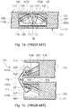
Figs. 1a and 1b , in general terms a prior art concealedhinge 101 includes afirst hinge body 103, adapted to be inserted into acorresponding cavity 107 of adoor frame 111, and asecond hinge body 105 adapted to be inserted into acorresponding cavity 109 of adoor leaf 113. - The
first hinge body 103 and thesecond hinge body 105 are mutually connected by means of afirst hinge arm 115 and asecond hinge arm 117 which are rotatably connected by means of apivot pin 119. Afirst end 115a of thefirst hinge arm 115 is rotatably connected to arotation pin 121 which is fixedly attached to thefirst hinge body 103, and thesecond end 115b of thefirst hinge arm 115 is rotatably connected to asliding pin 125 which in turn is slidably mounted in aguide groove 129 provided in thesecond hinge body 105. Correspondingly, afirst end 117a of thesecond hinge arm 117 is rotatably connected to arotation pin 123, which is fixedly attached to thesecond hinge body 105, and thesecond end 117b of thesecond hinge arm 117 is rotatably connected to asliding pin 127, which in turn is slidably mounted in aguide groove 131 provided in thefirst hinge body 103. -
Guide grooves Figs. 1a, 1b ) or curvilinear. As clearly shown inFig. 1a , saidguide grooves pivot pin 119 and perpendicular to the aligned surfaces ofdoor frame 111 anddoor leaf 113 when the door is closed. - Thanks to the structure of the concealed hinge described above, the door leaf can perform a rotary-translational movement allowing opening said door leaf by up to 180° relative to the door frame without interferences.
- Yet, such a solution is not devoid of drawbacks. In particular, the prior art concealed hinges are suitable for use with advantage when they are applied to interior doors, but they cannot be applied in similarly advantageous manner to exterior doors.
- Actually, in case of exterior doors, it is to be taken into account that one or more seals are to be provided around the door profile on the door leaf and/or the door frame in correspondence of suitable abutments. Said seals aim at providing an effective thermal and acoustic insulation while providing permeability to air and at the same time tightness to water and humidity. In order to ensure that the above aims are achieved, said seals are to be suitably compressed, and hence deformed, when the door is closed.
- In the case of the prior art concealed hinges, like those shown in
Figs. 1a and 1b , the rotary-translational movement of the door leaf relative to the frame is uniform and constant. - As a first consequence, during the initial portion of the door opening movement, the door leaf is not sufficiently spaced apart from the frame, and the abutment bearing the seal on the door leaf could interfere with the door frame and vice versa.
- As a second and more serious consequence, in the end portion of the door closing movement, the door leaf moves in a direction which is substantially parallel to the surface of the door frame, so that it is impossible to apply the adequate compression to the door seals.
- Therefore, it is the main object of the present invention to provide an improved concealed hinge that allows overcoming the limitations of the prior art hinges.
- More particularly, it is the main object of the present invention to provide an improved concealed hinge that, if applied to a door having one or more seals between the door leaf and the door frame, allows taking into account the need to house and to properly compress and deform said one or more seals.
- The above and other objects are achieved by the concealed hinge according to the invention, as claimed in the appended claims.
- A concealed hinge according to the invention includes a first hinge body adapted to be secured to a door frame, a second hinge body adapted to be secured to a door leaf, and a pair of hinge arms which are rotatably connected together by means of a pivot pin. The first hinge arm is rotatably connected at one end to a rotation pin which is fixedly attached to the first hinge body, and at the opposite end to a sliding pin which in turn is slidably mounted in one or more guide grooves provided in the second hinge body. The second hinge arm is rotatably connected at one end to a rotation pin which is fixedly attached to the second hinge body, and at the opposite end to a sliding pin which in turn is slidably mounted in one or more guide grooves provided in the first hinge body.
- According to the invention, the guide groove provided in the first hinge body and the guide groove provided in the second hinge body are curvilinear and they do not exhibit a mirror-like symmetry with respect to a plane passing through the pivot axis of the hinge arms and perpendicular to the aligned surfaces of the door frame and the door leaf when the door is closed.
- On the contrary, said guide grooves are made so that the guide groove in one of said hinge bodies is curvilinear and has its concavity facing the pivot axis of the hinge arms, and the guide groove of the other one of said hinge bodies is curvilinear and has its concavity facing away from the pivot axis of the hinge arms, i.e. it has its convexity facing the pivot axis of the hinge arms. The guide groove provided in the hinge body secured to the door leaf is shaped as an arc of which the concavity faces the pivot axis of the hinge arms, and the guide groove provided in the hinge body secured to the door frame is shaped as an arc of which the convexity faces the pivot axis of the hinge arms.
- Thanks to the asymmetrical configuration of the guide grooves of the hinge according to the invention it is possible to achieve a non-uniform rotary-translational movement of the door leaf relative to the door frame: along the opening/closing path of the door leaf it is possible to achieve some path sections in which the movement is mainly, or even substantially, a translational movement, and other sections in which the movement is mainly, or even substantially, a rotary movement.
- More particularly, in case of application to doors providing for the use of seals between the door frame and the door leaf, thanks to the structure of the hinge according to the invention, it will be possible to obtain that, in the initial portion of the door opening movement, and hence in the end portion of the door closing movement, respectively, the door leaf movement is mainly, or even substantially, a translational movement in a direction substantially perpendicular to the plane of the frame of the door itself.
- Thanks to such a measure, during opening the door leaf can rotate without interferences relative to the frame notwithstanding the provision of the abutments housing the seal. Moreover, thanks to such a measure, it will be possible to enable opening the door leaf by 180° without interferences between the hinge parts and the abutment bearing the seal, as on the contrary would occur with the prior art solutions. Always thanks to such a measure, during closure the seals can become properly compressed and deformed.
- Other features and advantages of the invention will become more apparent from the detailed description of a preferred embodiment of the invention itself, given hereinbelow by way of non-limiting example with reference to the accompanying drawings, in which:
-
Figs. 1a, 1b are cross-sectional views showing an example of a concealed hinge according to the prior art, shown in two different configurations; -
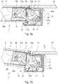
Fig. 2 is a perspective view showing a concealed hinge according to a preferred embodiment of the invention; -
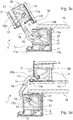
Figs. 3a to 3d are cross-sectional views, taken along line III - III, of the concealed hinge ofFig. 2 , shown in four different configurations. - Hereinafter, reference will be made to a preferred embodiment of the invention, relating to the application to an exterior door.
- Referring first to
Fig. 2 , a concealed hinge according to the invention is shown, denoted in the whole by reference numeral 1. - Said concealed hinge 1 includes a
first hinge body 3 adapted to be secured to the stationary door frame (not shown inFig. 2 for the sake of clarity), and asecond hinge body 5 adapted to be secured to the movable door leaf (not shown inFig. 2 for the sake of clarity). Thefirst hinge body 3 and thesecond hinge body 5 are provided withrespective holes - The
first hinge body 3 and thesecond hinge body 5 are mutually connected through afirst hinge arm 15 and asecond hinge arm 17, which are rotatably connected by means of apivot pin 19 defining a pivot axis for saidhinge arms - Advantageously, the material and the geometry of
hinge arms - More particularly, in the illustrated embodiment, the
first arm 15 is substantially H-shaped, with the vertical side arms extending over the whole height ofhinge bodies second arm 17 extends over the whole height ofhinge bodies first arm 15 and its rotation. - The structure and the operation of
hinge arms Figs. 3a to 3d , in which the hinge is shown as being applied to an exterior door including adoor frame 11 secured to awall 10 and amovable door leaf 13 associated with the frame. The sequence fromFig. 3a to Fig. 3d shows the door opening sequence from a closed door configuration (Fig. 3a ) to a wholly open door configuration (Fig. 3d ), in whichdoor leaf 13 is rotated by 180° relative to the door frame. The door closure sequence takes place according to the reverse sequence, that is, from the configuration shown inFig. 3d to the configuration shown inFig. 3a . - In order to ensure a proper thermal insulation, the exterior door is equipped with suitable seals extending along the profile of the door itself. A
first seal 12 is applied todoor frame 11 and, to this end, saiddoor frame 11 has, on its side facing the interior, a projectingperipheral edge 11a acting as an abutment fordoor leaf 13, and saidfirst seal 12 is applied onto the face of said projectingperipheral edge 11a facingdoor leaf 13. Asecond seal 14 is applied todoor leaf 13 and, to this end, saiddoor leaf 13 has, on its side facing the interior, a projectingperipheral edge 13a acting as an abutment fordoor frame 11, and saidsecond seal 14 is applied onto the face of said projectingperipheral edge 13a facingdoor frame 11. When the door is closed (seeFig. 3a ),door leaf 13 abuts againstperipheral edge 11a ofdoor frame 11,peripheral edge 13a ofdoor leaf 13 abuts againstdoor frame 11 and seals 12, 14 are compressed between said door leaf and said door frame and consequently are suitably deformed. In this way, it is possible to ensure a proper thermal and acoustic insulation as well as a proper permeability to air and a proper tightness to water and humidity. -
Door leaf 13 is hinged todoor frame 11 through one or more concealed hinges 1 according to the invention. - Thanks to the provision of concealed hinges,
door leaf 13 can rotate by 180° relative to door frame 11 (seeFig. 3d ) and, when the door is closed (seeFig. 3a ), no hinge element can be seen from the outside - As shown in detail in
Figs. 3a to 3d , thefirst hinge body 3 and thesecond hinge body 5 are mutually connected through afirst hinge arm 15 and asecond hinge arm 17, which are rotatably connected by means of apivot pin 19 defining a pivot axis for said hingearms - A
first end 15a of thefirst hinge arm 15 is rotatably connected to arotation pin 21 which is fixedly attached to thefirst hinge body 3, and thesecond end 15b of thefirst hinge arm 15 is rotatably connected to a slidingpin 25 the ends of which are slidably mounted inside a pair ofguide grooves 29 provided in the bottom wall and the top wall, respectively, of thesecond hinge body 5, only the groove provided in the bottom wall being visible in the Figures. - Correspondingly, a
first end 17a of thesecond hinge arm 17 is rotatably connected to arotation pin 23 which is fixedly attached to thesecond hinge body 5 and thesecond end 17b of thesecond hinge arm 17 is rotatably connected to a slidingpin 27 the ends of which are slidably mounted inside a pair ofguide grooves 31 provided in the bottom wall and the top wall, respectively, of thefirst hinge body 3, only the groove provided in the bottom wall being visible in the Figures. - Thanks to the provision of
guide grooves hinge arms door leaf 13 connected todoor frame 11 by means of hinge 1 is obtained, which movement allows opening and closing the door. - According to the invention, guide
grooves second hinge bodies pivot pin 19 and perpendicular to the aligned surfaces ofdoor frame 11 anddoor leaf 13 when the door is closed. - On the contrary, according to the invention, the guide grooves in one of the hinge bodies are curvilinear and their concavities face the pivot axis of the hinge, whereas the guide grooves in the other hinge body are curvilinear and their convexities face the pivot axis of the hinge. More particularly, referring to the embodiment shown in
Figs. 3a - 3d , guidegrooves 31 of the second hinge body are curvilinear and their concavities facepivot axis 19 of hinge 1, whereasguide grooves 29 of the first hinge body are curvilinear and their convexities facepivot axis 19 of hinge 1. According to the invention and shown inFigs. 3a - 3d , guidegrooves grooves Figs. 3a - 3d , guidegrooves pivot pin 19. Yet, but not according to the invention, guidegrooves - Moreover, even though in the preferred embodiment of the invention shown in
Figs. 3a - 3d each hinge body has a pair of guide grooves provided in the bottom wall and the top wall, respectively, of said hinge bodies, a single groove guide could even be provided for each hinge body. - Thanks to the asymmetrical configuration of
guide grooves hinge bodies door leaf 13 relative todoor frame 11 is not uniform. On the contrary, it is possible to achieve a door leaf movement that in some sections is mainly or only a translational movement, with little or no rotation, and in other sections is mainly or only a rotary movement, with little or no translation. - More particularly, with the configuration shown in the Figures, during the door opening movement, starting from the closed door configuration (
Fig. 3a ), initially a mainly translational movement ofdoor leaf 13 in perpendicular direction to the plane of door frame 11 (arrow F), with little rotation (Fig. 3b ), will take place . - As shown in
Fig. 3b , thanks to such a substantially translational movement,door leaf 13 will become sufficiently spaced fromdoor frame 11 to enable the subsequent rotation of saiddoor leaf 13, without interference of projectingperipheral edge 13a of the door leaf bearing thesecond seal 14 withdoor frame 11 or interference of saiddoor leaf 13 with projectingperipheral edge 11a ofdoor frame 11 bearing the first seal 12 (Fig. 3c ). - In the end portion of the door opening movement, a mainly rotary movement of
door leaf 13 will instead take place, eventually bringing saiddoor leaf 13 to a wholly open position, at 180° relative to door frame 11 (Fig. 3d ). - Conversely, during the door closing movement, initially a mainly rotary movement of
door leaf 13 will take place (from the configuration shown inFig. 3d to that shown inFig. 3c and then to that shown inFig. 3b ). Instead, in the end portion of the door closing movement, a mainly translational movement in perpendicular direction to the plane of door frame 11 (from the configuration shown inFig. 3b to the configuration shown inFig. 3a ) will take place, whereby seals 12, 14 will be properly compressed and deformed. - It will therefore be apparent to the skilled in the art that the concealed hinge according to the invention as disclosed above allows effectively attaining the intended objects.
- Moreover, it will be apparent to the skilled in the art that several changes and modifications can be made in the concealed hinge according to the invention, without thereby departing from the scope of the invention as defined in the following claims.
- In particular, even if the concealed hinge according to the invention is advantageously applicable to exterior doors, the invention is not to be considered for that reason as being limited to such an application. On the contrary, the invention could be applied to other cases in which one or more seals are provided between a movable leaf and the corresponding frame (one could think for instance to the leaf of a fridge door). More generally, the invention could be advantageously applied in all cases in which it is preferable to have a non-uniform rotary-translational movement of the movable leaf relative to the frame.
Claims (6)
- Concealed hinge (1) of the type comprising a first hinge body (3) adapted to be fixed to a stationary frame, and a second hinge body (5) adapted to be fixed to a movable leaf, wherein said first hinge body (3) and said second hinge body (5) are mutually connected by means of a first hinge arm (15) and a second hinge arm (17) which are rotatably connected by means of a pivot pin (19), said pivot pin (19) defining a pivot axis, wherein a first end (15a) of said first hinge arm (15) is rotatably connected to a rotation pin (21) which is fixedly attached to said first hinge body (3) and the second end (15b) of said first hinge arm (15) is rotatably connected to a sliding pin (25) which is slidably mounted in at least one guide groove (29) provided in said second hinge body (5), and wherein a first end (17a) of the second hinge arm (17) is rotatably connected to a rotation pin (23) which is fixedly attached to said second hinge body (5) and the second end (17b) of said second hinge arm (17) is rotatably connected to a sliding pin (27) which is slidably mounted in at least one guide groove (31) provided in said first hinge body (3), wherein said guide grooves (29, 31) of said first and second hinge bodies (3, 5) are curvilinear, said at least one guide groove (29, 31) of one of said hinge bodies (3, 5) having its concavity facing said pivot axis (19) of said hinge, and said at least one guide groove (31, 29) of the other one of said hinge bodies (5, 3) having its convexity facing said pivot axis of said hinge, characterized in that said guide grooves (29, 31) of said first and second hinge bodies (3, 5) have a circular arc shape and they have the same curvature radius.
- Concealed hinge (1) according to claim 1, wherein said at least one guide groove (29) of said second hinge body (5) has its concavity facing said pivot axis of said hinge, and said at least one guide groove (31) of said first hinge body has its convexity facing said pivot axis of said hinge.
- Concealed hinge (1) according to claim 1 or 2, wherein said guide grooves (29, 31) of said first and second hinge bodies (3, 5) have the same extension.
- Door, of the type comprising a door frame (11) which is stationary and a door leaf (13) which is mounted so as to be movable relative to said door frame (11), characterized in that said door leaf (13) is hinged to said door frame (11) by means of one or more hinges (1) according to any of the claims 1 to 3.
- Door according to claim 4, wherein said door frame (11) has a projecting peripheral edge (11a) adapted to serve as an abutment for said door leaf (13) and a seal (12) mounted on the side of said projecting peripheral edge (11a) facing said door leaf (13).
- Door according to claim 4 or 5, wherein said door leaf (13) has a projecting peripheral edge (13a) adapted to act as an abutment for said door frame (11) and a seal (14) mounted on the side of said projecting peripheral edge (13a) facing said door frame (11).
Priority Applications (1)
| Application Number | Priority Date | Filing Date | Title |
|---|---|---|---|
| PL16194775T PL3176353T3 (en) | 2015-12-04 | 2016-10-20 | Concealed hinge |
Applications Claiming Priority (1)
| Application Number | Priority Date | Filing Date | Title |
|---|---|---|---|
| ITUB2015A006253A ITUB20156253A1 (en) | 2015-12-04 | 2015-12-04 | Concealed hinge |
Publications (2)
| Publication Number | Publication Date |
|---|---|
| EP3176353A1 EP3176353A1 (en) | 2017-06-07 |
| EP3176353B1 true EP3176353B1 (en) | 2018-07-04 |
Family
ID=55588388
Family Applications (1)
| Application Number | Title | Priority Date | Filing Date |
|---|---|---|---|
| EP16194775.9A Active EP3176353B1 (en) | 2015-12-04 | 2016-10-20 | Concealed hinge |
Country Status (3)
| Country | Link |
|---|---|
| EP (1) | EP3176353B1 (en) |
| IT (1) | ITUB20156253A1 (en) |
| PL (1) | PL3176353T3 (en) |
Cited By (2)
| Publication number | Priority date | Publication date | Assignee | Title |
|---|---|---|---|---|
| WO2021141599A1 (en) * | 2020-01-10 | 2021-07-15 | Hewlett-Packard Development Company, L.P. | Door hinge |
| EP4180600A1 (en) * | 2021-11-16 | 2023-05-17 | Simonswerk GmbH | Hinge |
Families Citing this family (3)
| Publication number | Priority date | Publication date | Assignee | Title |
|---|---|---|---|---|
| GB2580139A (en) * | 2018-12-21 | 2020-07-15 | Aanco Uk Ltd | Hinge for folding doors |
| CN114144563B (en) * | 2019-07-11 | 2023-09-05 | 世嘉智尼工业株式会社 | Hinge device |
| AT524532B1 (en) * | 2020-12-28 | 2022-07-15 | Peer Robert | Arrangement of a hinge with a wall and a wing |
Family Cites Families (6)
| Publication number | Priority date | Publication date | Assignee | Title |
|---|---|---|---|---|
| US1484093A (en) | 1921-11-21 | 1924-02-19 | Soss Joseph | Hinge |
| US1688996A (en) | 1926-03-01 | 1928-10-23 | Soss Joseph | Concealed hinge |
| US2122034A (en) * | 1937-03-19 | 1938-06-28 | Jackle Johann | Hinge |
| EP1577474A3 (en) * | 2004-03-19 | 2010-07-07 | Dr. Hahn GmbH & Co. KG | Hinge for concealed mounting between frame and wing |
| DE102005039509B3 (en) * | 2005-08-20 | 2006-06-22 | Simonswerk, Gmbh | Door hinge e.g. for masked assembly between door frame and case, has two adapter bodies positioned in recesses in frame and in door case with two hinge handles swivelinglly connected around vertical connecting axle |
| FR2892143B1 (en) * | 2005-10-14 | 2009-02-20 | Peugeot Citroen Automobiles Sa | MECHANISM FOR THE JOINING OF A SUNROOF ON A MOTOR VEHICLE STRUCTURE AND VEHICLE COMPRISING SUCH A MECHANISM |
-
2015
- 2015-12-04 IT ITUB2015A006253A patent/ITUB20156253A1/en unknown
-
2016
- 2016-10-20 PL PL16194775T patent/PL3176353T3/en unknown
- 2016-10-20 EP EP16194775.9A patent/EP3176353B1/en active Active
Non-Patent Citations (1)
| Title |
|---|
| None * |
Cited By (2)
| Publication number | Priority date | Publication date | Assignee | Title |
|---|---|---|---|---|
| WO2021141599A1 (en) * | 2020-01-10 | 2021-07-15 | Hewlett-Packard Development Company, L.P. | Door hinge |
| EP4180600A1 (en) * | 2021-11-16 | 2023-05-17 | Simonswerk GmbH | Hinge |
Also Published As
| Publication number | Publication date |
|---|---|
| EP3176353A1 (en) | 2017-06-07 |
| ITUB20156253A1 (en) | 2017-06-04 |
| PL3176353T3 (en) | 2019-01-31 |
Similar Documents
| Publication | Publication Date | Title |
|---|---|---|
| EP3176353B1 (en) | Concealed hinge | |
| KR200436903Y1 (en) | Casement Window | |
| US20090273264A1 (en) | Flapper mechanism for a refrigerator | |
| EP3034973B1 (en) | Refrigerator | |
| RU2015106113A (en) | DOOR HINGE | |
| KR101779561B1 (en) | Folding door | |
| KR101528662B1 (en) | Sliding window having airtight apparatus | |
| KR100602218B1 (en) | The sealing device of refrigeration room door for french door type refrigerator | |
| EP2781676B1 (en) | Concealed hinge with an automatic return device toward a closed position | |
| CN112154247A (en) | Hinge device for refrigerator and furniture | |
| WO2018189643A1 (en) | Concealed hinge | |
| EP2886762B1 (en) | Multi-link hinge | |
| ATE279629T1 (en) | FITTING UNIT FOR A WINDOW OR DOOR | |
| KR20140114329A (en) | Door for easily mounting gasket | |
| EP3353364B1 (en) | Sash for doors or windows and door or window obtained with the sash | |
| FR2194865B1 (en) | ||
| EP3353365B1 (en) | Sash for doors or windows | |
| KR200459030Y1 (en) | Door assembly for clean room | |
| CN210918807U (en) | Wine cabinet sealing structure | |
| WO2018002805A3 (en) | Hinge for the rotatable movement of a door or of a similar closing element | |
| ES2338531T3 (en) | FRIDGE WITH A DOOR SECURITY DEVICE. | |
| KR100458798B1 (en) | Hinge for door | |
| KR20190002371U (en) | Member for Covering Open Gap of Door | |
| KR20180130799A (en) | Multifunctional hinge | |
| FI92093C (en) | Hinge for door or similar structure |
Legal Events
| Date | Code | Title | Description |
|---|---|---|---|
| AK | Designated contracting states |
Kind code of ref document: A1 Designated state(s): AL AT BE BG CH CY CZ DE DK EE ES FI FR GB GR HR HU IE IS IT LI LT LU LV MC MK MT NL NO PL PT RO RS SE SI SK SM TR |
|
| AX | Request for extension of the european patent |
Extension state: BA ME |
|
| PUAI | Public reference made under article 153(3) epc to a published international application that has entered the european phase |
Free format text: ORIGINAL CODE: 0009012 |
|
| 17P | Request for examination filed |
Effective date: 20171011 |
|
| RBV | Designated contracting states (corrected) |
Designated state(s): AL AT BE BG CH CY CZ DE DK EE ES FI FR GB GR HR HU IE IS IT LI LT LU LV MC MK MT NL NO PL PT RO RS SE SI SK SM TR |
|
| GRAP | Despatch of communication of intention to grant a patent |
Free format text: ORIGINAL CODE: EPIDOSNIGR1 |
|
| INTG | Intention to grant announced |
Effective date: 20180206 |
|
| GRAS | Grant fee paid |
Free format text: ORIGINAL CODE: EPIDOSNIGR3 |
|
| GRAA | (expected) grant |
Free format text: ORIGINAL CODE: 0009210 |
|
| AK | Designated contracting states |
Kind code of ref document: B1 Designated state(s): AL AT BE BG CH CY CZ DE DK EE ES FI FR GB GR HR HU IE IS IT LI LT LU LV MC MK MT NL NO PL PT RO RS SE SI SK SM TR |
|
| REG | Reference to a national code |
Ref country code: GB Ref legal event code: FG4D |
|
| REG | Reference to a national code |
Ref country code: CH Ref legal event code: EP |
|
| REG | Reference to a national code |
Ref country code: AT Ref legal event code: REF Ref document number: 1014686 Country of ref document: AT Kind code of ref document: T Effective date: 20180715 |
|
| REG | Reference to a national code |
Ref country code: IE Ref legal event code: FG4D |
|
| REG | Reference to a national code |
Ref country code: CH Ref legal event code: NV Representative=s name: IPWAY DI FRANCESCO FABIO AND CO., CH |
|
| REG | Reference to a national code |
Ref country code: DE Ref legal event code: R096 Ref document number: 602016003969 Country of ref document: DE |
|
| REG | Reference to a national code |
Ref country code: FR Ref legal event code: PLFP Year of fee payment: 3 |
|
| REG | Reference to a national code |
Ref country code: NL Ref legal event code: MP Effective date: 20180704 |
|
| REG | Reference to a national code |
Ref country code: LT Ref legal event code: MG4D |
|
| REG | Reference to a national code |
Ref country code: AT Ref legal event code: MK05 Ref document number: 1014686 Country of ref document: AT Kind code of ref document: T Effective date: 20180704 |
|
| PG25 | Lapsed in a contracting state [announced via postgrant information from national office to epo] |
Ref country code: NL Free format text: LAPSE BECAUSE OF FAILURE TO SUBMIT A TRANSLATION OF THE DESCRIPTION OR TO PAY THE FEE WITHIN THE PRESCRIBED TIME-LIMIT Effective date: 20180704 |
|
| PG25 | Lapsed in a contracting state [announced via postgrant information from national office to epo] |
Ref country code: NO Free format text: LAPSE BECAUSE OF FAILURE TO SUBMIT A TRANSLATION OF THE DESCRIPTION OR TO PAY THE FEE WITHIN THE PRESCRIBED TIME-LIMIT Effective date: 20181004 Ref country code: GR Free format text: LAPSE BECAUSE OF FAILURE TO SUBMIT A TRANSLATION OF THE DESCRIPTION OR TO PAY THE FEE WITHIN THE PRESCRIBED TIME-LIMIT Effective date: 20181005 Ref country code: SE Free format text: LAPSE BECAUSE OF FAILURE TO SUBMIT A TRANSLATION OF THE DESCRIPTION OR TO PAY THE FEE WITHIN THE PRESCRIBED TIME-LIMIT Effective date: 20180704 Ref country code: FI Free format text: LAPSE BECAUSE OF FAILURE TO SUBMIT A TRANSLATION OF THE DESCRIPTION OR TO PAY THE FEE WITHIN THE PRESCRIBED TIME-LIMIT Effective date: 20180704 Ref country code: LT Free format text: LAPSE BECAUSE OF FAILURE TO SUBMIT A TRANSLATION OF THE DESCRIPTION OR TO PAY THE FEE WITHIN THE PRESCRIBED TIME-LIMIT Effective date: 20180704 Ref country code: RS Free format text: LAPSE BECAUSE OF FAILURE TO SUBMIT A TRANSLATION OF THE DESCRIPTION OR TO PAY THE FEE WITHIN THE PRESCRIBED TIME-LIMIT Effective date: 20180704 Ref country code: CZ Free format text: LAPSE BECAUSE OF FAILURE TO SUBMIT A TRANSLATION OF THE DESCRIPTION OR TO PAY THE FEE WITHIN THE PRESCRIBED TIME-LIMIT Effective date: 20180704 Ref country code: IS Free format text: LAPSE BECAUSE OF FAILURE TO SUBMIT A TRANSLATION OF THE DESCRIPTION OR TO PAY THE FEE WITHIN THE PRESCRIBED TIME-LIMIT Effective date: 20181104 Ref country code: AT Free format text: LAPSE BECAUSE OF FAILURE TO SUBMIT A TRANSLATION OF THE DESCRIPTION OR TO PAY THE FEE WITHIN THE PRESCRIBED TIME-LIMIT Effective date: 20180704 Ref country code: BG Free format text: LAPSE BECAUSE OF FAILURE TO SUBMIT A TRANSLATION OF THE DESCRIPTION OR TO PAY THE FEE WITHIN THE PRESCRIBED TIME-LIMIT Effective date: 20181004 |
|
| PG25 | Lapsed in a contracting state [announced via postgrant information from national office to epo] |
Ref country code: LV Free format text: LAPSE BECAUSE OF FAILURE TO SUBMIT A TRANSLATION OF THE DESCRIPTION OR TO PAY THE FEE WITHIN THE PRESCRIBED TIME-LIMIT Effective date: 20180704 Ref country code: AL Free format text: LAPSE BECAUSE OF FAILURE TO SUBMIT A TRANSLATION OF THE DESCRIPTION OR TO PAY THE FEE WITHIN THE PRESCRIBED TIME-LIMIT Effective date: 20180704 Ref country code: HR Free format text: LAPSE BECAUSE OF FAILURE TO SUBMIT A TRANSLATION OF THE DESCRIPTION OR TO PAY THE FEE WITHIN THE PRESCRIBED TIME-LIMIT Effective date: 20180704 |
|
| REG | Reference to a national code |
Ref country code: DE Ref legal event code: R097 Ref document number: 602016003969 Country of ref document: DE |
|
| PG25 | Lapsed in a contracting state [announced via postgrant information from national office to epo] |
Ref country code: EE Free format text: LAPSE BECAUSE OF FAILURE TO SUBMIT A TRANSLATION OF THE DESCRIPTION OR TO PAY THE FEE WITHIN THE PRESCRIBED TIME-LIMIT Effective date: 20180704 Ref country code: RO Free format text: LAPSE BECAUSE OF FAILURE TO SUBMIT A TRANSLATION OF THE DESCRIPTION OR TO PAY THE FEE WITHIN THE PRESCRIBED TIME-LIMIT Effective date: 20180704 Ref country code: IT Free format text: LAPSE BECAUSE OF FAILURE TO SUBMIT A TRANSLATION OF THE DESCRIPTION OR TO PAY THE FEE WITHIN THE PRESCRIBED TIME-LIMIT Effective date: 20180704 |
|
| PLBE | No opposition filed within time limit |
Free format text: ORIGINAL CODE: 0009261 |
|
| STAA | Information on the status of an ep patent application or granted ep patent |
Free format text: STATUS: NO OPPOSITION FILED WITHIN TIME LIMIT |
|
| PG25 | Lapsed in a contracting state [announced via postgrant information from national office to epo] |
Ref country code: SK Free format text: LAPSE BECAUSE OF FAILURE TO SUBMIT A TRANSLATION OF THE DESCRIPTION OR TO PAY THE FEE WITHIN THE PRESCRIBED TIME-LIMIT Effective date: 20180704 Ref country code: DK Free format text: LAPSE BECAUSE OF FAILURE TO SUBMIT A TRANSLATION OF THE DESCRIPTION OR TO PAY THE FEE WITHIN THE PRESCRIBED TIME-LIMIT Effective date: 20180704 Ref country code: SM Free format text: LAPSE BECAUSE OF FAILURE TO SUBMIT A TRANSLATION OF THE DESCRIPTION OR TO PAY THE FEE WITHIN THE PRESCRIBED TIME-LIMIT Effective date: 20180704 |
|
| 26N | No opposition filed |
Effective date: 20190405 |
|
| REG | Reference to a national code |
Ref country code: BE Ref legal event code: MM Effective date: 20181031 |
|
| PG25 | Lapsed in a contracting state [announced via postgrant information from national office to epo] |
Ref country code: MC Free format text: LAPSE BECAUSE OF FAILURE TO SUBMIT A TRANSLATION OF THE DESCRIPTION OR TO PAY THE FEE WITHIN THE PRESCRIBED TIME-LIMIT Effective date: 20180704 Ref country code: LU Free format text: LAPSE BECAUSE OF NON-PAYMENT OF DUE FEES Effective date: 20181020 |
|
| REG | Reference to a national code |
Ref country code: IE Ref legal event code: MM4A |
|
| PG25 | Lapsed in a contracting state [announced via postgrant information from national office to epo] |
Ref country code: ES Free format text: LAPSE BECAUSE OF FAILURE TO SUBMIT A TRANSLATION OF THE DESCRIPTION OR TO PAY THE FEE WITHIN THE PRESCRIBED TIME-LIMIT Effective date: 20180704 |
|
| PG25 | Lapsed in a contracting state [announced via postgrant information from national office to epo] |
Ref country code: SI Free format text: LAPSE BECAUSE OF FAILURE TO SUBMIT A TRANSLATION OF THE DESCRIPTION OR TO PAY THE FEE WITHIN THE PRESCRIBED TIME-LIMIT Effective date: 20180704 Ref country code: BE Free format text: LAPSE BECAUSE OF NON-PAYMENT OF DUE FEES Effective date: 20181031 |
|
| PG25 | Lapsed in a contracting state [announced via postgrant information from national office to epo] |
Ref country code: IE Free format text: LAPSE BECAUSE OF NON-PAYMENT OF DUE FEES Effective date: 20181020 |
|
| PG25 | Lapsed in a contracting state [announced via postgrant information from national office to epo] |
Ref country code: MT Free format text: LAPSE BECAUSE OF NON-PAYMENT OF DUE FEES Effective date: 20181020 |
|
| PG25 | Lapsed in a contracting state [announced via postgrant information from national office to epo] |
Ref country code: TR Free format text: LAPSE BECAUSE OF FAILURE TO SUBMIT A TRANSLATION OF THE DESCRIPTION OR TO PAY THE FEE WITHIN THE PRESCRIBED TIME-LIMIT Effective date: 20180704 |
|
| PG25 | Lapsed in a contracting state [announced via postgrant information from national office to epo] |
Ref country code: PT Free format text: LAPSE BECAUSE OF FAILURE TO SUBMIT A TRANSLATION OF THE DESCRIPTION OR TO PAY THE FEE WITHIN THE PRESCRIBED TIME-LIMIT Effective date: 20180704 |
|
| PG25 | Lapsed in a contracting state [announced via postgrant information from national office to epo] |
Ref country code: CY Free format text: LAPSE BECAUSE OF FAILURE TO SUBMIT A TRANSLATION OF THE DESCRIPTION OR TO PAY THE FEE WITHIN THE PRESCRIBED TIME-LIMIT Effective date: 20180704 Ref country code: HU Free format text: LAPSE BECAUSE OF FAILURE TO SUBMIT A TRANSLATION OF THE DESCRIPTION OR TO PAY THE FEE WITHIN THE PRESCRIBED TIME-LIMIT; INVALID AB INITIO Effective date: 20161020 Ref country code: MK Free format text: LAPSE BECAUSE OF NON-PAYMENT OF DUE FEES Effective date: 20180704 |
|
| GBPC | Gb: european patent ceased through non-payment of renewal fee |
Effective date: 20201020 |
|
| PG25 | Lapsed in a contracting state [announced via postgrant information from national office to epo] |
Ref country code: GB Free format text: LAPSE BECAUSE OF NON-PAYMENT OF DUE FEES Effective date: 20201020 |
|
| PGFP | Annual fee paid to national office [announced via postgrant information from national office to epo] |
Ref country code: PL Payment date: 20220923 Year of fee payment: 7 |
|
| P01 | Opt-out of the competence of the unified patent court (upc) registered |
Effective date: 20230518 |
|
| PGFP | Annual fee paid to national office [announced via postgrant information from national office to epo] |
Ref country code: FR Payment date: 20231023 Year of fee payment: 8 Ref country code: DE Payment date: 20231024 Year of fee payment: 8 Ref country code: CH Payment date: 20231102 Year of fee payment: 8 |
|
| PGFP | Annual fee paid to national office [announced via postgrant information from national office to epo] |
Ref country code: PL Payment date: 20231003 Year of fee payment: 8 |