EP3176109A1 - Carrier for containers - Google Patents
Carrier for containers Download PDFInfo
- Publication number
- EP3176109A1 EP3176109A1 EP16201615.8A EP16201615A EP3176109A1 EP 3176109 A1 EP3176109 A1 EP 3176109A1 EP 16201615 A EP16201615 A EP 16201615A EP 3176109 A1 EP3176109 A1 EP 3176109A1
- Authority
- EP
- European Patent Office
- Prior art keywords
- panel
- top panel
- opening
- carrier
- locking
- Prior art date
- Legal status (The legal status is an assumption and is not a legal conclusion. Google has not performed a legal analysis and makes no representation as to the accuracy of the status listed.)
- Granted
Links
- 238000000034 method Methods 0.000 claims description 19
- 230000003213 activating effect Effects 0.000 claims description 5
- 239000000463 material Substances 0.000 description 13
- 239000000969 carrier Substances 0.000 description 11
- 239000000853 adhesive Substances 0.000 description 7
- 230000001070 adhesive effect Effects 0.000 description 7
- 239000003292 glue Substances 0.000 description 6
- 230000008901 benefit Effects 0.000 description 4
- 235000013361 beverage Nutrition 0.000 description 4
- 238000012986 modification Methods 0.000 description 3
- 230000004048 modification Effects 0.000 description 3
- 210000003739 neck Anatomy 0.000 description 3
- 230000015572 biosynthetic process Effects 0.000 description 2
- 239000004927 clay Substances 0.000 description 2
- 239000011248 coating agent Substances 0.000 description 2
- 238000000576 coating method Methods 0.000 description 2
- 239000011521 glass Substances 0.000 description 2
- 238000004806 packaging method and process Methods 0.000 description 2
- 230000000007 visual effect Effects 0.000 description 2
- 230000003313 weakening effect Effects 0.000 description 2
- VGGSQFUCUMXWEO-UHFFFAOYSA-N Ethene Chemical compound C=C VGGSQFUCUMXWEO-UHFFFAOYSA-N 0.000 description 1
- 229920000219 Ethylene vinyl alcohol Polymers 0.000 description 1
- 239000004677 Nylon Substances 0.000 description 1
- 239000004743 Polypropylene Substances 0.000 description 1
- 239000004793 Polystyrene Substances 0.000 description 1
- 238000007792 addition Methods 0.000 description 1
- 229910052782 aluminium Inorganic materials 0.000 description 1
- XAGFODPZIPBFFR-UHFFFAOYSA-N aluminium Chemical compound [Al] XAGFODPZIPBFFR-UHFFFAOYSA-N 0.000 description 1
- 238000013475 authorization Methods 0.000 description 1
- 230000004888 barrier function Effects 0.000 description 1
- 239000011111 cardboard Substances 0.000 description 1
- 230000000994 depressogenic effect Effects 0.000 description 1
- 238000001514 detection method Methods 0.000 description 1
- UFRKOOWSQGXVKV-UHFFFAOYSA-N ethene;ethenol Chemical compound C=C.OC=C UFRKOOWSQGXVKV-UHFFFAOYSA-N 0.000 description 1
- 239000004715 ethylene vinyl alcohol Substances 0.000 description 1
- 229920001903 high density polyethylene Polymers 0.000 description 1
- 239000004700 high-density polyethylene Substances 0.000 description 1
- 238000010348 incorporation Methods 0.000 description 1
- 238000003780 insertion Methods 0.000 description 1
- 230000037431 insertion Effects 0.000 description 1
- 229920000092 linear low density polyethylene Polymers 0.000 description 1
- 239000004707 linear low-density polyethylene Substances 0.000 description 1
- 229920001684 low density polyethylene Polymers 0.000 description 1
- 239000004702 low-density polyethylene Substances 0.000 description 1
- 230000013011 mating Effects 0.000 description 1
- 229910052751 metal Inorganic materials 0.000 description 1
- 239000002184 metal Substances 0.000 description 1
- 150000002739 metals Chemical class 0.000 description 1
- 239000000203 mixture Substances 0.000 description 1
- 229920001778 nylon Polymers 0.000 description 1
- 239000000123 paper Substances 0.000 description 1
- 239000011087 paperboard Substances 0.000 description 1
- 239000004033 plastic Substances 0.000 description 1
- 229920003023 plastic Polymers 0.000 description 1
- 229920000139 polyethylene terephthalate Polymers 0.000 description 1
- 239000005020 polyethylene terephthalate Substances 0.000 description 1
- 229920000915 polyvinyl chloride Polymers 0.000 description 1
- 239000004800 polyvinyl chloride Substances 0.000 description 1
- 238000012545 processing Methods 0.000 description 1
- 238000011144 upstream manufacturing Methods 0.000 description 1
- 239000002966 varnish Substances 0.000 description 1
Images


Classifications
-
- B—PERFORMING OPERATIONS; TRANSPORTING
- B31—MAKING ARTICLES OF PAPER, CARDBOARD OR MATERIAL WORKED IN A MANNER ANALOGOUS TO PAPER; WORKING PAPER, CARDBOARD OR MATERIAL WORKED IN A MANNER ANALOGOUS TO PAPER
- B31B—MAKING CONTAINERS OF PAPER, CARDBOARD OR MATERIAL WORKED IN A MANNER ANALOGOUS TO PAPER
- B31B50/00—Making rigid or semi-rigid containers, e.g. boxes or cartons
- B31B50/60—Uniting opposed surfaces or edges; Taping
- B31B50/73—Uniting opposed surfaces or edges; Taping by mechanically interlocking integral parts, e.g. by tongues and slots
- B31B50/732—Uniting opposed surfaces or edges; Taping by mechanically interlocking integral parts, e.g. by tongues and slots by folding or tucking-in locking flaps
-
- B—PERFORMING OPERATIONS; TRANSPORTING
- B65—CONVEYING; PACKING; STORING; HANDLING THIN OR FILAMENTARY MATERIAL
- B65D—CONTAINERS FOR STORAGE OR TRANSPORT OF ARTICLES OR MATERIALS, e.g. BAGS, BARRELS, BOTTLES, BOXES, CANS, CARTONS, CRATES, DRUMS, JARS, TANKS, HOPPERS, FORWARDING CONTAINERS; ACCESSORIES, CLOSURES, OR FITTINGS THEREFOR; PACKAGING ELEMENTS; PACKAGES
- B65D71/00—Bundles of articles held together by packaging elements for convenience of storage or transport, e.g. portable segregating carrier for plural receptacles such as beer cans or pop bottles; Bales of material
- B65D71/06—Packaging elements holding or encircling completely or almost completely the bundle of articles, e.g. wrappers
- B65D71/12—Packaging elements holding or encircling completely or almost completely the bundle of articles, e.g. wrappers the packaging elements, e.g. wrappers being formed by folding a single blank
- B65D71/36—Packaging elements holding or encircling completely or almost completely the bundle of articles, e.g. wrappers the packaging elements, e.g. wrappers being formed by folding a single blank having a tubular shape, e.g. tubular wrappers, with end walls
-
- B—PERFORMING OPERATIONS; TRANSPORTING
- B31—MAKING ARTICLES OF PAPER, CARDBOARD OR MATERIAL WORKED IN A MANNER ANALOGOUS TO PAPER; WORKING PAPER, CARDBOARD OR MATERIAL WORKED IN A MANNER ANALOGOUS TO PAPER
- B31B—MAKING CONTAINERS OF PAPER, CARDBOARD OR MATERIAL WORKED IN A MANNER ANALOGOUS TO PAPER
- B31B50/00—Making rigid or semi-rigid containers, e.g. boxes or cartons
- B31B50/60—Uniting opposed surfaces or edges; Taping
-
- B—PERFORMING OPERATIONS; TRANSPORTING
- B31—MAKING ARTICLES OF PAPER, CARDBOARD OR MATERIAL WORKED IN A MANNER ANALOGOUS TO PAPER; WORKING PAPER, CARDBOARD OR MATERIAL WORKED IN A MANNER ANALOGOUS TO PAPER
- B31B—MAKING CONTAINERS OF PAPER, CARDBOARD OR MATERIAL WORKED IN A MANNER ANALOGOUS TO PAPER
- B31B50/00—Making rigid or semi-rigid containers, e.g. boxes or cartons
- B31B50/74—Auxiliary operations
-
- B—PERFORMING OPERATIONS; TRANSPORTING
- B65—CONVEYING; PACKING; STORING; HANDLING THIN OR FILAMENTARY MATERIAL
- B65D—CONTAINERS FOR STORAGE OR TRANSPORT OF ARTICLES OR MATERIALS, e.g. BAGS, BARRELS, BOTTLES, BOXES, CANS, CARTONS, CRATES, DRUMS, JARS, TANKS, HOPPERS, FORWARDING CONTAINERS; ACCESSORIES, CLOSURES, OR FITTINGS THEREFOR; PACKAGING ELEMENTS; PACKAGES
- B65D5/00—Rigid or semi-rigid containers of polygonal cross-section, e.g. boxes, cartons or trays, formed by folding or erecting one or more blanks made of paper
- B65D5/02—Rigid or semi-rigid containers of polygonal cross-section, e.g. boxes, cartons or trays, formed by folding or erecting one or more blanks made of paper by folding or erecting a single blank to form a tubular body with or without subsequent folding operations, or the addition of separate elements, to close the ends of the body
- B65D5/10—Rigid or semi-rigid containers of polygonal cross-section, e.g. boxes, cartons or trays, formed by folding or erecting one or more blanks made of paper by folding or erecting a single blank to form a tubular body with or without subsequent folding operations, or the addition of separate elements, to close the ends of the body with end closures formed by inward-folding of self-locking flaps hinged to tubular body
- B65D5/103—Rigid or semi-rigid containers of polygonal cross-section, e.g. boxes, cartons or trays, formed by folding or erecting one or more blanks made of paper by folding or erecting a single blank to form a tubular body with or without subsequent folding operations, or the addition of separate elements, to close the ends of the body with end closures formed by inward-folding of self-locking flaps hinged to tubular body one of the self-locking flaps having a tongue engaging into an opening of an opposite flap
- B65D5/106—Rigid or semi-rigid containers of polygonal cross-section, e.g. boxes, cartons or trays, formed by folding or erecting one or more blanks made of paper by folding or erecting a single blank to form a tubular body with or without subsequent folding operations, or the addition of separate elements, to close the ends of the body with end closures formed by inward-folding of self-locking flaps hinged to tubular body one of the self-locking flaps having a tongue engaging into an opening of an opposite flap the opening being a slot
-
- B—PERFORMING OPERATIONS; TRANSPORTING
- B65—CONVEYING; PACKING; STORING; HANDLING THIN OR FILAMENTARY MATERIAL
- B65D—CONTAINERS FOR STORAGE OR TRANSPORT OF ARTICLES OR MATERIALS, e.g. BAGS, BARRELS, BOTTLES, BOXES, CANS, CARTONS, CRATES, DRUMS, JARS, TANKS, HOPPERS, FORWARDING CONTAINERS; ACCESSORIES, CLOSURES, OR FITTINGS THEREFOR; PACKAGING ELEMENTS; PACKAGES
- B65D5/00—Rigid or semi-rigid containers of polygonal cross-section, e.g. boxes, cartons or trays, formed by folding or erecting one or more blanks made of paper
- B65D5/42—Details of containers or of foldable or erectable container blanks
- B65D5/4266—Folding lines, score lines, crease lines
-
- B—PERFORMING OPERATIONS; TRANSPORTING
- B65—CONVEYING; PACKING; STORING; HANDLING THIN OR FILAMENTARY MATERIAL
- B65D—CONTAINERS FOR STORAGE OR TRANSPORT OF ARTICLES OR MATERIALS, e.g. BAGS, BARRELS, BOTTLES, BOXES, CANS, CARTONS, CRATES, DRUMS, JARS, TANKS, HOPPERS, FORWARDING CONTAINERS; ACCESSORIES, CLOSURES, OR FITTINGS THEREFOR; PACKAGING ELEMENTS; PACKAGES
- B65D5/00—Rigid or semi-rigid containers of polygonal cross-section, e.g. boxes, cartons or trays, formed by folding or erecting one or more blanks made of paper
- B65D5/42—Details of containers or of foldable or erectable container blanks
- B65D5/44—Integral, inserted or attached portions forming internal or external fittings
- B65D5/46—Handles
- B65D5/46072—Handles integral with the container
- B65D5/46088—Handles integral with the container formed by extensions of closure flaps, by closure flaps or by extensions of side flaps of a container formed by folding a blank to form a tubular body
-
- B—PERFORMING OPERATIONS; TRANSPORTING
- B65—CONVEYING; PACKING; STORING; HANDLING THIN OR FILAMENTARY MATERIAL
- B65D—CONTAINERS FOR STORAGE OR TRANSPORT OF ARTICLES OR MATERIALS, e.g. BAGS, BARRELS, BOTTLES, BOXES, CANS, CARTONS, CRATES, DRUMS, JARS, TANKS, HOPPERS, FORWARDING CONTAINERS; ACCESSORIES, CLOSURES, OR FITTINGS THEREFOR; PACKAGING ELEMENTS; PACKAGES
- B65D5/00—Rigid or semi-rigid containers of polygonal cross-section, e.g. boxes, cartons or trays, formed by folding or erecting one or more blanks made of paper
- B65D5/42—Details of containers or of foldable or erectable container blanks
- B65D5/44—Integral, inserted or attached portions forming internal or external fittings
- B65D5/48—Partitions
- B65D5/48002—Partitions integral
- B65D5/48016—Partitions integral formed by folding extensions hinged to the upper or lower edges of a tubular body
-
- B—PERFORMING OPERATIONS; TRANSPORTING
- B65—CONVEYING; PACKING; STORING; HANDLING THIN OR FILAMENTARY MATERIAL
- B65D—CONTAINERS FOR STORAGE OR TRANSPORT OF ARTICLES OR MATERIALS, e.g. BAGS, BARRELS, BOTTLES, BOXES, CANS, CARTONS, CRATES, DRUMS, JARS, TANKS, HOPPERS, FORWARDING CONTAINERS; ACCESSORIES, CLOSURES, OR FITTINGS THEREFOR; PACKAGING ELEMENTS; PACKAGES
- B65D71/00—Bundles of articles held together by packaging elements for convenience of storage or transport, e.g. portable segregating carrier for plural receptacles such as beer cans or pop bottles; Bales of material
- B65D71/0003—Tray-like elements provided with handles, for storage or transport of several articles, e.g. bottles, tins, jars
- B65D71/0029—Tray-like elements provided with handles, for storage or transport of several articles, e.g. bottles, tins, jars formed by folding one blank so as to form a tubular element in which the upper wall is provided with openings through which the articles extend partially
- B65D71/0033—Tray-like elements provided with handles, for storage or transport of several articles, e.g. bottles, tins, jars formed by folding one blank so as to form a tubular element in which the upper wall is provided with openings through which the articles extend partially with parts of the walls bent against one another so as to form a longitudinal partition for two rows of articles
- B65D71/0037—Tray-like elements provided with handles, for storage or transport of several articles, e.g. bottles, tins, jars formed by folding one blank so as to form a tubular element in which the upper wall is provided with openings through which the articles extend partially with parts of the walls bent against one another so as to form a longitudinal partition for two rows of articles with additional locating elements for the articles
-
- B—PERFORMING OPERATIONS; TRANSPORTING
- B65—CONVEYING; PACKING; STORING; HANDLING THIN OR FILAMENTARY MATERIAL
- B65D—CONTAINERS FOR STORAGE OR TRANSPORT OF ARTICLES OR MATERIALS, e.g. BAGS, BARRELS, BOTTLES, BOXES, CANS, CARTONS, CRATES, DRUMS, JARS, TANKS, HOPPERS, FORWARDING CONTAINERS; ACCESSORIES, CLOSURES, OR FITTINGS THEREFOR; PACKAGING ELEMENTS; PACKAGES
- B65D71/00—Bundles of articles held together by packaging elements for convenience of storage or transport, e.g. portable segregating carrier for plural receptacles such as beer cans or pop bottles; Bales of material
- B65D71/0003—Tray-like elements provided with handles, for storage or transport of several articles, e.g. bottles, tins, jars
- B65D71/0029—Tray-like elements provided with handles, for storage or transport of several articles, e.g. bottles, tins, jars formed by folding one blank so as to form a tubular element in which the upper wall is provided with openings through which the articles extend partially
- B65D71/0033—Tray-like elements provided with handles, for storage or transport of several articles, e.g. bottles, tins, jars formed by folding one blank so as to form a tubular element in which the upper wall is provided with openings through which the articles extend partially with parts of the walls bent against one another so as to form a longitudinal partition for two rows of articles
- B65D71/004—Tray-like elements provided with handles, for storage or transport of several articles, e.g. bottles, tins, jars formed by folding one blank so as to form a tubular element in which the upper wall is provided with openings through which the articles extend partially with parts of the walls bent against one another so as to form a longitudinal partition for two rows of articles with individual openings for holding the articles
-
- B—PERFORMING OPERATIONS; TRANSPORTING
- B31—MAKING ARTICLES OF PAPER, CARDBOARD OR MATERIAL WORKED IN A MANNER ANALOGOUS TO PAPER; WORKING PAPER, CARDBOARD OR MATERIAL WORKED IN A MANNER ANALOGOUS TO PAPER
- B31B—MAKING CONTAINERS OF PAPER, CARDBOARD OR MATERIAL WORKED IN A MANNER ANALOGOUS TO PAPER
- B31B2100/00—Rigid or semi-rigid containers made by folding single-piece sheets, blanks or webs
-
- B—PERFORMING OPERATIONS; TRANSPORTING
- B31—MAKING ARTICLES OF PAPER, CARDBOARD OR MATERIAL WORKED IN A MANNER ANALOGOUS TO PAPER; WORKING PAPER, CARDBOARD OR MATERIAL WORKED IN A MANNER ANALOGOUS TO PAPER
- B31B—MAKING CONTAINERS OF PAPER, CARDBOARD OR MATERIAL WORKED IN A MANNER ANALOGOUS TO PAPER
- B31B2100/00—Rigid or semi-rigid containers made by folding single-piece sheets, blanks or webs
- B31B2100/002—Rigid or semi-rigid containers made by folding single-piece sheets, blanks or webs characterised by the shape of the blank from which they are formed
- B31B2100/0024—Rigid or semi-rigid containers made by folding single-piece sheets, blanks or webs characterised by the shape of the blank from which they are formed having all side walls attached to the bottom
-
- B—PERFORMING OPERATIONS; TRANSPORTING
- B31—MAKING ARTICLES OF PAPER, CARDBOARD OR MATERIAL WORKED IN A MANNER ANALOGOUS TO PAPER; WORKING PAPER, CARDBOARD OR MATERIAL WORKED IN A MANNER ANALOGOUS TO PAPER
- B31B—MAKING CONTAINERS OF PAPER, CARDBOARD OR MATERIAL WORKED IN A MANNER ANALOGOUS TO PAPER
- B31B2120/00—Construction of rigid or semi-rigid containers
- B31B2120/20—Construction of rigid or semi-rigid containers provided with two or more compartments
-
- B—PERFORMING OPERATIONS; TRANSPORTING
- B31—MAKING ARTICLES OF PAPER, CARDBOARD OR MATERIAL WORKED IN A MANNER ANALOGOUS TO PAPER; WORKING PAPER, CARDBOARD OR MATERIAL WORKED IN A MANNER ANALOGOUS TO PAPER
- B31B—MAKING CONTAINERS OF PAPER, CARDBOARD OR MATERIAL WORKED IN A MANNER ANALOGOUS TO PAPER
- B31B50/00—Making rigid or semi-rigid containers, e.g. boxes or cartons
- B31B50/74—Auxiliary operations
- B31B50/81—Forming or attaching accessories, e.g. opening devices, closures or tear strings
-
- B—PERFORMING OPERATIONS; TRANSPORTING
- B31—MAKING ARTICLES OF PAPER, CARDBOARD OR MATERIAL WORKED IN A MANNER ANALOGOUS TO PAPER; WORKING PAPER, CARDBOARD OR MATERIAL WORKED IN A MANNER ANALOGOUS TO PAPER
- B31B—MAKING CONTAINERS OF PAPER, CARDBOARD OR MATERIAL WORKED IN A MANNER ANALOGOUS TO PAPER
- B31B50/00—Making rigid or semi-rigid containers, e.g. boxes or cartons
- B31B50/74—Auxiliary operations
- B31B50/81—Forming or attaching accessories, e.g. opening devices, closures or tear strings
- B31B50/86—Forming integral handles; Attaching separate handles
-
- B—PERFORMING OPERATIONS; TRANSPORTING
- B65—CONVEYING; PACKING; STORING; HANDLING THIN OR FILAMENTARY MATERIAL
- B65D—CONTAINERS FOR STORAGE OR TRANSPORT OF ARTICLES OR MATERIALS, e.g. BAGS, BARRELS, BOTTLES, BOXES, CANS, CARTONS, CRATES, DRUMS, JARS, TANKS, HOPPERS, FORWARDING CONTAINERS; ACCESSORIES, CLOSURES, OR FITTINGS THEREFOR; PACKAGING ELEMENTS; PACKAGES
- B65D2571/00—Bundles of articles held together by packaging elements for convenience of storage or transport, e.g. portable segregating carrier for plural receptacles such as beer cans, pop bottles; Bales of material
- B65D2571/00123—Bundling wrappers or trays
- B65D2571/00129—Wrapper locking means
- B65D2571/00135—Wrapper locking means integral with the wrapper
- B65D2571/00154—Wrapper locking means integral with the wrapper interlocked
- B65D2571/0016—Wrapper locking means integral with the wrapper interlocked by tabs protruding from one end and co-operating with openings at the other end
-
- B—PERFORMING OPERATIONS; TRANSPORTING
- B65—CONVEYING; PACKING; STORING; HANDLING THIN OR FILAMENTARY MATERIAL
- B65D—CONTAINERS FOR STORAGE OR TRANSPORT OF ARTICLES OR MATERIALS, e.g. BAGS, BARRELS, BOTTLES, BOXES, CANS, CARTONS, CRATES, DRUMS, JARS, TANKS, HOPPERS, FORWARDING CONTAINERS; ACCESSORIES, CLOSURES, OR FITTINGS THEREFOR; PACKAGING ELEMENTS; PACKAGES
- B65D2571/00—Bundles of articles held together by packaging elements for convenience of storage or transport, e.g. portable segregating carrier for plural receptacles such as beer cans, pop bottles; Bales of material
- B65D2571/00123—Bundling wrappers or trays
- B65D2571/00246—Locating elements for the contents
- B65D2571/00253—Locating elements for the contents integral with the wrapper
- B65D2571/0029—Openings in top or bottom walls
-
- B—PERFORMING OPERATIONS; TRANSPORTING
- B65—CONVEYING; PACKING; STORING; HANDLING THIN OR FILAMENTARY MATERIAL
- B65D—CONTAINERS FOR STORAGE OR TRANSPORT OF ARTICLES OR MATERIALS, e.g. BAGS, BARRELS, BOTTLES, BOXES, CANS, CARTONS, CRATES, DRUMS, JARS, TANKS, HOPPERS, FORWARDING CONTAINERS; ACCESSORIES, CLOSURES, OR FITTINGS THEREFOR; PACKAGING ELEMENTS; PACKAGES
- B65D2571/00—Bundles of articles held together by packaging elements for convenience of storage or transport, e.g. portable segregating carrier for plural receptacles such as beer cans, pop bottles; Bales of material
- B65D2571/00123—Bundling wrappers or trays
- B65D2571/00333—Partitions, i.e. elements contacting a major part of each aarticle or extending across the whole length of the wrapper
- B65D2571/00339—Partitions, i.e. elements contacting a major part of each aarticle or extending across the whole length of the wrapper extending from the upper or lower wall
-
- B—PERFORMING OPERATIONS; TRANSPORTING
- B65—CONVEYING; PACKING; STORING; HANDLING THIN OR FILAMENTARY MATERIAL
- B65D—CONTAINERS FOR STORAGE OR TRANSPORT OF ARTICLES OR MATERIALS, e.g. BAGS, BARRELS, BOTTLES, BOXES, CANS, CARTONS, CRATES, DRUMS, JARS, TANKS, HOPPERS, FORWARDING CONTAINERS; ACCESSORIES, CLOSURES, OR FITTINGS THEREFOR; PACKAGING ELEMENTS; PACKAGES
- B65D2571/00—Bundles of articles held together by packaging elements for convenience of storage or transport, e.g. portable segregating carrier for plural receptacles such as beer cans, pop bottles; Bales of material
- B65D2571/00123—Bundling wrappers or trays
- B65D2571/00333—Partitions, i.e. elements contacting a major part of each aarticle or extending across the whole length of the wrapper
- B65D2571/0037—Partitions, i.e. elements contacting a major part of each aarticle or extending across the whole length of the wrapper extending from at least a side wall
-
- B—PERFORMING OPERATIONS; TRANSPORTING
- B65—CONVEYING; PACKING; STORING; HANDLING THIN OR FILAMENTARY MATERIAL
- B65D—CONTAINERS FOR STORAGE OR TRANSPORT OF ARTICLES OR MATERIALS, e.g. BAGS, BARRELS, BOTTLES, BOXES, CANS, CARTONS, CRATES, DRUMS, JARS, TANKS, HOPPERS, FORWARDING CONTAINERS; ACCESSORIES, CLOSURES, OR FITTINGS THEREFOR; PACKAGING ELEMENTS; PACKAGES
- B65D2571/00—Bundles of articles held together by packaging elements for convenience of storage or transport, e.g. portable segregating carrier for plural receptacles such as beer cans, pop bottles; Bales of material
- B65D2571/00123—Bundling wrappers or trays
- B65D2571/00432—Handles or suspending means
- B65D2571/00438—Holes
- B65D2571/0045—Holes for hands
-
- B—PERFORMING OPERATIONS; TRANSPORTING
- B65—CONVEYING; PACKING; STORING; HANDLING THIN OR FILAMENTARY MATERIAL
- B65D—CONTAINERS FOR STORAGE OR TRANSPORT OF ARTICLES OR MATERIALS, e.g. BAGS, BARRELS, BOTTLES, BOXES, CANS, CARTONS, CRATES, DRUMS, JARS, TANKS, HOPPERS, FORWARDING CONTAINERS; ACCESSORIES, CLOSURES, OR FITTINGS THEREFOR; PACKAGING ELEMENTS; PACKAGES
- B65D2571/00—Bundles of articles held together by packaging elements for convenience of storage or transport, e.g. portable segregating carrier for plural receptacles such as beer cans, pop bottles; Bales of material
- B65D2571/00123—Bundling wrappers or trays
- B65D2571/00432—Handles or suspending means
- B65D2571/00456—Handles or suspending means integral with the wrapper
-
- B—PERFORMING OPERATIONS; TRANSPORTING
- B65—CONVEYING; PACKING; STORING; HANDLING THIN OR FILAMENTARY MATERIAL
- B65D—CONTAINERS FOR STORAGE OR TRANSPORT OF ARTICLES OR MATERIALS, e.g. BAGS, BARRELS, BOTTLES, BOXES, CANS, CARTONS, CRATES, DRUMS, JARS, TANKS, HOPPERS, FORWARDING CONTAINERS; ACCESSORIES, CLOSURES, OR FITTINGS THEREFOR; PACKAGING ELEMENTS; PACKAGES
- B65D2571/00—Bundles of articles held together by packaging elements for convenience of storage or transport, e.g. portable segregating carrier for plural receptacles such as beer cans, pop bottles; Bales of material
- B65D2571/00123—Bundling wrappers or trays
- B65D2571/00432—Handles or suspending means
- B65D2571/00456—Handles or suspending means integral with the wrapper
- B65D2571/00475—Handles or suspending means integral with the wrapper and extending ion a substantially vertical plane
- B65D2571/00487—Handles or suspending means integral with the wrapper and extending ion a substantially vertical plane and formed integrally with a partition
-
- B—PERFORMING OPERATIONS; TRANSPORTING
- B65—CONVEYING; PACKING; STORING; HANDLING THIN OR FILAMENTARY MATERIAL
- B65D—CONTAINERS FOR STORAGE OR TRANSPORT OF ARTICLES OR MATERIALS, e.g. BAGS, BARRELS, BOTTLES, BOXES, CANS, CARTONS, CRATES, DRUMS, JARS, TANKS, HOPPERS, FORWARDING CONTAINERS; ACCESSORIES, CLOSURES, OR FITTINGS THEREFOR; PACKAGING ELEMENTS; PACKAGES
- B65D2571/00—Bundles of articles held together by packaging elements for convenience of storage or transport, e.g. portable segregating carrier for plural receptacles such as beer cans, pop bottles; Bales of material
- B65D2571/00123—Bundling wrappers or trays
- B65D2571/00555—Wrapper opening devices
- B65D2571/00561—Lines of weakness
- B65D2571/00574—Lines of weakness whereby contents can still be carried after the line has been torn
-
- B—PERFORMING OPERATIONS; TRANSPORTING
- B65—CONVEYING; PACKING; STORING; HANDLING THIN OR FILAMENTARY MATERIAL
- B65D—CONTAINERS FOR STORAGE OR TRANSPORT OF ARTICLES OR MATERIALS, e.g. BAGS, BARRELS, BOTTLES, BOXES, CANS, CARTONS, CRATES, DRUMS, JARS, TANKS, HOPPERS, FORWARDING CONTAINERS; ACCESSORIES, CLOSURES, OR FITTINGS THEREFOR; PACKAGING ELEMENTS; PACKAGES
- B65D2571/00—Bundles of articles held together by packaging elements for convenience of storage or transport, e.g. portable segregating carrier for plural receptacles such as beer cans, pop bottles; Bales of material
- B65D2571/00123—Bundling wrappers or trays
- B65D2571/00648—Elements used to form the wrapper
- B65D2571/00654—Blanks
- B65D2571/0066—Blanks formed from one single sheet
-
- B—PERFORMING OPERATIONS; TRANSPORTING
- B65—CONVEYING; PACKING; STORING; HANDLING THIN OR FILAMENTARY MATERIAL
- B65D—CONTAINERS FOR STORAGE OR TRANSPORT OF ARTICLES OR MATERIALS, e.g. BAGS, BARRELS, BOTTLES, BOXES, CANS, CARTONS, CRATES, DRUMS, JARS, TANKS, HOPPERS, FORWARDING CONTAINERS; ACCESSORIES, CLOSURES, OR FITTINGS THEREFOR; PACKAGING ELEMENTS; PACKAGES
- B65D2571/00—Bundles of articles held together by packaging elements for convenience of storage or transport, e.g. portable segregating carrier for plural receptacles such as beer cans, pop bottles; Bales of material
- B65D2571/00123—Bundling wrappers or trays
- B65D2571/00709—Shape of the formed wrapper, i.e. shape of each formed element if the wrapper is made from more than one element
- B65D2571/00722—Shape of the formed wrapper, i.e. shape of each formed element if the wrapper is made from more than one element tubular with end walls, e.g. walls not extending on the whole end surface
- B65D2571/00728—Shape of the formed wrapper, i.e. shape of each formed element if the wrapper is made from more than one element tubular with end walls, e.g. walls not extending on the whole end surface the end walls being closed by gluing
-
- B—PERFORMING OPERATIONS; TRANSPORTING
- B65—CONVEYING; PACKING; STORING; HANDLING THIN OR FILAMENTARY MATERIAL
- B65D—CONTAINERS FOR STORAGE OR TRANSPORT OF ARTICLES OR MATERIALS, e.g. BAGS, BARRELS, BOTTLES, BOXES, CANS, CARTONS, CRATES, DRUMS, JARS, TANKS, HOPPERS, FORWARDING CONTAINERS; ACCESSORIES, CLOSURES, OR FITTINGS THEREFOR; PACKAGING ELEMENTS; PACKAGES
- B65D2571/00—Bundles of articles held together by packaging elements for convenience of storage or transport, e.g. portable segregating carrier for plural receptacles such as beer cans, pop bottles; Bales of material
- B65D2571/00123—Bundling wrappers or trays
- B65D2571/00709—Shape of the formed wrapper, i.e. shape of each formed element if the wrapper is made from more than one element
- B65D2571/00722—Shape of the formed wrapper, i.e. shape of each formed element if the wrapper is made from more than one element tubular with end walls, e.g. walls not extending on the whole end surface
- B65D2571/00734—Shape of the formed wrapper, i.e. shape of each formed element if the wrapper is made from more than one element tubular with end walls, e.g. walls not extending on the whole end surface the end walls being closed by heat sealing
-
- B—PERFORMING OPERATIONS; TRANSPORTING
- B65—CONVEYING; PACKING; STORING; HANDLING THIN OR FILAMENTARY MATERIAL
- B65D—CONTAINERS FOR STORAGE OR TRANSPORT OF ARTICLES OR MATERIALS, e.g. BAGS, BARRELS, BOTTLES, BOXES, CANS, CARTONS, CRATES, DRUMS, JARS, TANKS, HOPPERS, FORWARDING CONTAINERS; ACCESSORIES, CLOSURES, OR FITTINGS THEREFOR; PACKAGING ELEMENTS; PACKAGES
- B65D2571/00—Bundles of articles held together by packaging elements for convenience of storage or transport, e.g. portable segregating carrier for plural receptacles such as beer cans, pop bottles; Bales of material
- B65D2571/00123—Bundling wrappers or trays
- B65D2571/00709—Shape of the formed wrapper, i.e. shape of each formed element if the wrapper is made from more than one element
- B65D2571/00722—Shape of the formed wrapper, i.e. shape of each formed element if the wrapper is made from more than one element tubular with end walls, e.g. walls not extending on the whole end surface
- B65D2571/00753—Shape of the formed wrapper, i.e. shape of each formed element if the wrapper is made from more than one element tubular with end walls, e.g. walls not extending on the whole end surface the end walls being closed by interlocking
Definitions
- the present disclosure generally relates to carriers or cartons for holding and displaying containers. More specifically, the present disclosure relates to basket-style carriers.
- a carrier for holding a plurality of containers comprises a plurality of panels that extends at least partially around an interior of the carrier.
- the plurality of panels comprises at least one bottom panel, at least one top panel, a front panel, a back panel, at least one side panel, and at least one central panel dividing the interior of the carrier into a front portion and a back portion.
- At least one divider flap is foldably connected to the at least one central panel and extends to one of the front panel and the back panel to divide one of the front portion and the back portion into at least two container-receiving spaces.
- the at least one top panel is foldably connected to at least one of the front panel and the back panel and includes at least one opening for receiving a container of the plurality of containers.
- the at least one top panel comprises a locking tab and the at least one central panel comprises a locking opening for receiving the locking tab.
- a blank for forming a carrier for holding a plurality of containers comprises a plurality of panels for extending at least partially around an interior of the carrier formed from the blank and comprising at least one bottom panel, at least one top panel, a front panel, a back panel, at least one side panel, and at least one central panel for dividing the interior of the carrier formed from the blank into a front portion and a back portion.
- At least one divider flap is foldably connected to the at least one central panel and is for extending to one of the front panel and the back panel to divide one of the front portion and the back portion into at least two container-receiving spaces in the carrier formed from the blank.
- the at least one top panel is foldably connected to at least one of the front panel and the back panel and includes at least one opening for receiving a container of the plurality of containers.
- the blank comprises locking feature including a locking tab in the at least one top panel and a locking opening in the at least one central panel for receiving the locking tab in the carrier formed from the blank.
- a method of forming a carrier for holding a plurality of containers comprises obtaining a blank having a plurality of panels that comprises at least one bottom panel, at least one top panel, a front panel, a back panel, at least one side panel, and at least one central panel, at least one divider flap foldably connected to the at least one central panel and extending to one of the front panel and the back panel, the at least one top panel is foldably connected to at least one of the front panel and the back panel and includes at least one opening for receiving a container of the plurality of containers.
- the blank comprises locking features comprising a locking tab in the at least one top panel and a locking opening in the at least one central panel.
- the method comprises positioning the plurality of panels to extend at least partially around an interior of the carrier, positioning the at least one central panel to divide the interior of the carrier into a front portion and a back portion, positioning the at least one divider panel to extending to one of the front panel and the back panel to divide one of the front portion and the back portion into at least two container-receiving spaces, and activating the locking features to lock the at least one top panel.
- the activating the locking features comprises inserting the locking tab into the locking opening.
- the present disclosure generally relates to carriers, packages, constructs, sleeves, cartons, or the like, for holding and displaying containers such as jars, bottles, cans, etc.
- the containers can be used for packaging food and beverage products, for example.
- the containers can be made from materials suitable in composition for packaging the particular food or beverage item, and the materials include, but are not limited to, glass; plastics such as PET, LDPE, LLDPE, HDPE, PP, PS, PVC, EVOH, and Nylon; and the like; aluminum and/or other metals; or any combination thereof.
- Carriers according to the present disclosure can accommodate containers of numerous different shapes.
- beverage containers e.g., glass bottles
- the terms “lower,” “bottom,” “upper,” “top,” “front,” and “back” indicate orientations determined in relation to fully erected carriers.
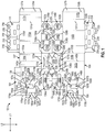
- Fig. 1 is a plan view of an interior side 101 of a blank 103 used to form a package or basket-style carrier 105 ( Fig. 7 ), in accordance with an exemplary embodiment of the present disclosure.
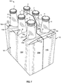
- the carrier 105 is sized to contain six containers C, three containers being contained in a front portion 108 of the carrier 105 and three containers being contained in a back portion 110 of the carrier 105.
- the containers C are beverage bottles with necks N, or the like, that extend upwardly to just below the caps P of the containers C, but the containers C could be any other suitable type and size of container without departing from the disclosure.
- the carrier 105 may be sized and shaped to hold more or less than six containers C.
- the carrier 105 includes a four-ply handle 172 for grasping the carrier 105 and top panels 136a, 136b having pilfer-proof or pilfer detection features for controlling product removal and providing visual tamper evidence as well as locking features for facilitating formation of the carrier and maintaining the top panels in place.
- the blank 103 has a longitudinal axis L1 and a lateral axis L2.
- the blank 103 has a front portion 107 for forming the front portion of the carrier 105, a back portion 109 for forming the back portion 110 of the carrier, a bottom panel 111 foldably connected to the front portion 107, and a bottom connective flap 113 foldably connected to the back portion 109.
- the front portion 107 and back portion 109 are for being folded about a longitudinal centerline CL of the blank 103 when the blank 103 is formed into the carrier 105.
- the bottom panel 111 and the connective flap 113 may be oppositely arranged without departing from the disclosure.
- the blank 103 is formed into the carrier 105 by folding the blank 103 about the centerline CL so that the front portion 107 and the back portion 109 are overlapped.
- the front portion 107 comprises a front panel 115a foldably connected to a first side panel 117a and a second side panel 119a.
- Lateral fold lines 131a, 133a foldably connect a respective first and second side panel 117a, 119a to the front panel 115a.
- the front panel 115a is connected to the bottom panel 111 along a longitudinal fold line 135a.
- An adhesive flap 127a is foldably connected to the first side panel 117a at a lateral fold line 129a.
- the front portion 107 also includes a front handle panel 121a adjacent the second side panel 119a along a cut 123a extending in parallel with axis L1.
- the front handle panel 121a is separated from the second side panel 119a by the cut 123a.
- the front handle panel 121a includes a handle flap 125a foldably connected to the front handle panel 121a at a fold line 126a.
- the handle flap 125a may be an arcuate member that defines an at least partial opening, as shown.
- the front portion 107 includes a front or first central panel 141a foldably connected to the second side panel 119a at a lateral fold line 143a.
- the central panel 141a includes a keel 137 foldably connected to the central panel 141a at a longitudinal fold line 139, an opening 140a, and handle features for forming handle 172 ( Fig. 7 ).
- the handle features include a handle portion 134a of the central panel 141a that includes a handle opening 145a.
- the front handle panel 121a is foldably connected to the handle portion 134a of the first central panel 141a at a lateral fold line 128a.
- the front handle panel 121a includes generally oblique outer edges 130a, 132a extending from the edges of respective fold line 128a and a cut line 124a associated with top panel 136a.
- the handle features also include oblique edges 164a, 170a of the handle portion 134a in the first central panel 141a that have a same or similar configuration to the oblique edges 130a, 132a of the front handle panel 121a such that when the blank 103 is formed into the carrier 105 the oblique edges 164a, 170a, 130a, 132a provide a shape to the handle 172 that facilitates positioning the handle 172 in the formed carrier 105, as described further herein.
- the front portion 107 of blank 103 also includes a first top panel 136a foldably connected to the front panel 115a at longitudinal fold line 138a.
- the first top panel 136a is partially defined by a longitudinal cut 158 that extends at least partially along centerline CL, as described further herein.
- the first top panel 136a is also separated from the handle panel 121a by the lateral cut 124a.
- the first top panel 136a includes three openings 142a, 144a, 146a for receiving the necks N of the containers C ( Fig. 7 ).
- openings 142a, 146a are circular and the opening 144a includes a semi-circular portion and a generally rectangular portion extending from the semi-circular portion to the front panel 115a and intersecting the fold line 138a.
- the openings 142a, 144a, 146a may be alternatively shaped, arranged, or configured without departing from the disclosure.
- the openings 142a, 144a, 146a include a respective expansion cut 148a, 150a, and 152a (broadly "expansion feature") extending from the openings 142a, 144a, 146a to provide controlled or guided tearing of the carrier 105 and removal of the containers C.
- expansion cuts 148a, 152a extend toward fold line 138a and expansion cut 150a extends toward cut 158 and/or the centerline CL.
- the top panel 136a may also include a tab 156a formed along the cut 158 for mating with the opening 140a in the first central panel 141a to hold the carrier 105 in the upright and fully erect position as shown in Figs. 7 , 7A , and 8 .
- a first divider flap 147a is foldably connected to the first central panel 141a at a lateral fold line 149a.
- a second divider flap 151a is foldably connected to the first central panel 141a at a lateral fold line 153a.
- Each divider flap 147a, 151a includes a respective attachment flap 155a, 157a foldably connected to the respective divider flap at a lateral fold line 159a, 161a.
- the first divider flap 147a is at least partially defined by an upper cut 165a, a lower cut 167a, a side cut 169a, and the lateral fold line 149a.
- the first attachment flap 155a is at least partially defined by upper cuts 165a, lower cuts 167a, lateral cuts 166a, 168a, and lateral fold lines 159a.
- the second divider flap 151a is at least partially defined by an upper cut 173a that extends from a lateral edge of the blank 103 to the fold line 153a, an upper edge 175a, a lower cut 178a that extend from a lateral edge of the blank 103 to the fold line 153a, and an upper lateral edge 180a and a lower lateral edge 179a corresponding to a lateral edge of the blank 103, and the lateral fold line 153a.
- the lower cut 178a of the second divider flap 151a may be collinear with the longitudinal fold line 139 associated with keel 137.
- the second attachment flap 157a is at least partially defined by the upper edge 175a, a lower edge 177a, a cut 184a, the upper lateral edge 180a, and lateral fold line 161a.
- the first and second divider flaps 147a, 151a are at least partially separable from the first central panel 141a and may be at least partially surrounded by the first central panel 141a.
- the features of the back portion 109 of the blank 103 include a back panel 115b, a first side panel 117b, a second side panel 119b, a second top panel 136b, a back handle panel 121b, and a central adhesive flap 127b that are generally a mirror-image of the corresponding panel or flap of the front portion 107.
- Corresponding components and features e.g., panels, flaps, fold lines, cuts, etc.
- corresponding reference numbers that differ by the "a” or "b” suffix, with the "a” components corresponding to the front portion 107 and the "b” components corresponding to the back portion 109 of the blank 103.
- the back portion 109 includes a back or second central panel 141b foldably connected to the fourth side panel 119b at a lateral fold line 143b.
- the central panel 141b includes a handle portion 134b with a handle opening 145b, and an opening 140b for at least partially receiving the tab 156b of the top panel 136b.
- a third divider flap 147b is foldably connected to the back central panel 141b at a lateral fold line 149b.
- a fourth divider flap 151b is foldably connected to the back central panel 141b at a lateral fold line 153b.
- Each divider flap 147b, 151b includes a respective adhesive flap 155b, 157b foldably connected to the respective divider flaps 147b, 151b at lateral fold lines 159b and 161b.
- the third divider flap 147b is at least partially defined by an upper cut 165b, a lower cut 167b, a side cut 169b, and the lateral fold lines 149b.
- the third attachment flap 155b is at least partially defined by the lower cuts 167b, the upper cuts 165b, side cuts 166b, 168b and lateral fold lines 159b.
- the fourth divider flap 151b is at least partially defined by an upper cut 173b that extends from a lateral edge of the blank 103 to the fold line 153b, an upper edge 175b, a lower edge 195, an upper lateral edge 180b and a lower lateral edge 179b corresponding to a lateral edge of the blank 103, and the lateral fold line 153b.
- the fourth attachment flap 157b is at least partially defined by the upper edge 175b, a lower edge 177b, a side cut 184b, the upper lateral edge 180a, and lateral fold line 161b.
- the third and fourth divider flaps 147b, 151b are at least partially separable from the second central panel 141b and may be at least partially surrounded by the second central panel 141b.
- the blank 103 includes a longitudinal fold line 225 that foldably connects the front central panel 141a and the back central panel 141b. Also, a longitudinal fold line 227 foldably connects the front handle panel 121a and the back handle panel 121b. A longitudinal fold line 229 foldably connects the first top panel 136a to the second top panel 136b. Portions of the longitudinal fold line 229 extend from respective ends of the cut 158. The cut 158 extends between portions of the first top panel 136a and the second top panel 136b and defines respective locking tabs 156a, 156b that are formed in respective adjacent edges of the first top panel and the second top panel.
- the longitudinal fold lines 225, 227, 229 are generally aligned with the longitudinal centerline CL of the blank 103 and portions of the cut 158 that are adjacent the respective locking tabs 156a, 156b are generally aligned with the longitudinal centerline CL of the blank.
- any of the panels, flaps, fold lines, cuts, or other features could be otherwise shaped, arranged, and/or omitted from the blank 103 without departing from the disclosure.
- the blank 103 could be sized and/or shaped to accommodate more or less than six containers without departing from this disclosure.
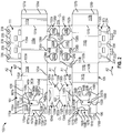
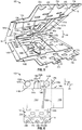
- the carrier 105 may be erected from the blank 103 by respectively folding the handle panels 121a, 121b in the direction of A1 along fold lines 128a, 128b so that the respective oblique edges 130a and 170a, 132a and 164a, 130b and 170b, and 132b and 164b are aligned and the handle panels 121a, 121b are in adjacent the central panels 141a, 141b along a line parallel to axis L1.
- the method includes folding the central panels 141a, 141b in the direction of arrows A2 ( Fig. 2 ) about fold lines 143a, 143b so that the central panels 141a, 141b are in an overlying face-to-face relationship with portions of the handle panels 121a, 121b and are adjacent the front and back panels 151a, 151b along a line parallel to axis L2.
- Glue or other adhesive is selectively applied to the blank 103 to adhesively connect the attachment flaps 155a, 157a to the front panel 115a with glue and to adhesively connect the adhesive flaps 155b, 157b to the back panel 115b.
- the keel 137 may also be folded about fold line 139 to be in overlying face-to-face contact and adhesively connected with an exterior surface 101 of the blank 103 along central panel 141a, as illustrated.
- the side panels 117a, 117b are folded in the direction of arrows A3 about fold lines 131a, 131b so that the side panels 117a, 117b and respective adhesive flaps 127a, 127b are in overlying face-to-face contact with portions of the central panels 141a, 141b and the central panels 141a, 141b can be selectively adhesively secured thereto, for example, with glue.
- the partially assembled blank 103 is folded in the direction of arrow A4 ( Fig. 5 ) about the longitudinal centerline CL so that the front portion 107 is in overlying face-to-face contact with the back portion 109.
- the blank 103 is further assembled into the carrier 105 by positioning the first side panels 117a, 117b and second side panels 119a, 119b to be in a generally spaced-apart, parallel planar relationship and positioning the front panel 115a and back panel 115b to be in a generally spaced-apart, parallel planar relationship.
- Such movement of the side panels 117a, 117b, 119a, 119b and front and back panels 115a, 115b causes the handle 172 and top panels 136a, 136 to move from a first position ( Fig.
- Fig. 6 wherein the handle 172 is generally parallel to and between the top panels 136a and 136b that are folded about fold line 229, to a second position ( Fig. 7 ) wherein the top panels 136a, 136b are downwardly folded about fold lines 138a, 138b to extend between the top of the front panel 115a and back panel 115b.
- handle 172 is moved to the left in the direction of arrow A5 ( Fig.
- the aligned oblique edges 130a and 170a, 132a and 164a, 130b and 170b, and 132b and 164b of central panels 141a, 141b and handle panels 121a, 121b may facilitate the insertion of handle 172 through cut 158, for example, by reducing catching or interference of the outer edges of handle 172 with portions of top panels 136a, 136b.
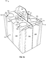
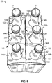
- the locking tabs 156a, 156b of the top panels 136a, 136b will engage the overlapped locking openings 140a, 140b in the overlapped central panels 141a, 141b to lock the top panels 136a, 136b in the position of Figs. 7 , 7A , and 8 so that the top panels 136a, 136b are generally planar relative to each other to form a top panel 154 of the carrier 105 that is generally perpendicular to the front and back panels 115a, 115b and side panels 117a, 117b, 119a, 119b.
- the positioning of the side panels 117a, 117b, 119a, 119b and front and back panels 115a, 115b causes the divider flaps 147a, 151a in the front portion 108 of the carrier 105 to be positioned generally perpendicular with the front panel 115a to divide the front portion into three container-receiving spaces 255.
- the rear portion 110 of the carrier 105 is divided into three container receiving spaces 257 by the divider flaps 147b, 151b.
- the bottom panel 111 and bottom connective flap 113 are folded and partially overlapped and locked to form an enclosed bottom of the carrier 105, as described further herein.
- the top panel of the carrier 105 is arranged such that the container receiving spaces 255, 257 are at least partially enclosed by the respective top panels 136a, 136b. While the openings 142a, 144a, 146a, 142b, 144b, 146b permit the partial protrusion, e.g., of necks N, of containers C above the top panels 136a, 136b, the top panels 136a, 136b are configured to be torn proximate the openings 142a, 144a, 146a, 142b, 144b, 146b in order to remove containers C from the container receiving spaces 255, 257.
- top panels 136a, 136b may be facilitated by expansion features such as expansion cuts 148a, 150a, and 152a adjacent openings 142a, 144a, 146a and expansion features such as expansion cuts 148b, 150b, and 152b adjacent openings 142b, 144b, 146b.
- expansion features such as expansion cuts 148a, 150a, and 152a adjacent openings 142a, 144a, 146a
- expansion features such as expansion cuts 148b, 150b, and 152b adjacent openings 142b, 144b, 146b.
- top panels 136a, 136b may influence the behavior of one or more persons who may desire to remove one or more containers C without authorization.
- unauthorized removal of containers C from a carrier 105 may occur, for example, in shelves or refrigerated cases in retail locations, e.g., convenience stores, grocery stores, or gas stations, in which persons may remove selected containers from carriers in order to mix-and-match with or to fill a different carrier of containers.
- the expansion features 148a, 148b, 150a, 150b, 152a, 152b could be other lines of weakening other than cuts (e.g., tear lines, cut/crease lines, notches, slits, openings, etc.) and could be otherwise shaped such as to be other than straight lines without departing from the disclosure.
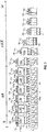
- FIG. 9 illustrates the various stages of the loading and assembly of the carrier 105 in sequence from left to right.
- the carton infeed stage I where the partially assembled blank 103 or open bottomed carrier 106 is fed to the forming area in the folded flat configuration generally illustrated in Fig. 6 .
- the carton opening stage II is adjacent the carton infeed stage and the folded flat, open bottomed carrier 106 of the carton infeed stage is progressed through a folding/positioning apparatus (not shown) and opened by positioning the front and back panels 115a, 115b and side panels 117a, 117b, 119a, 119b relative to each other, downwardly folding the top panels 136a, 136b, and positioning the handle panel to be inserted through the cut 158 between the top panels 136a, 136b.
- the locking tabs 156a, 156b are inserted through the overlapped locking openings 145a, 145b in the central panels 141a, 141b to lock the top panels 136a, 136b in the opened configuration of the open bottomed carrier 106 so that the container receiving spaces 255, 277 are formed.
- the open bottomed carrier 106 is conveyed to the product loading stage III, wherein the open bottom carrier 106 from the discharge of the carton opening stage II is lowered onto a group of six containers C. As shown in Fig.
- the open-bottomed carriers 106 are lowered onto groups of containers C during the product loading stage III so that the containers C enter a respective container-receiving space 255, 257 and each container C extends through an opening 142a, 144a, 146a and 142b, 144b, 146b in the respective top panels 136a, 136b.
- the bottom connective flap 113 is connected to the bottom panel 111, for example, by glue or by mechanical attachment wherein the bottom connective flap 113 comprises locking portions 233, 234 which interlock with respective openings or cuts 235 and openings 236.
- locking portions 233, 234 may be tabs as illustrated, or may have a different configuration for interengagement with openings or cuts 235 and openings 236.
- the bottom of the carrier 105 is closed and the bottoms of the containers C are supported by the bottom wall formed from the bottom panel 111 and bottom connective flap 113 of the carrier 105.
- the loaded and closed carrier 105 is conveyed at the product outfeed stage IV to a location for further processing such as loading for bulk shipment.
- the stages I, II, III, IV of the formation and loading of the carrier 105 from the blank 103 are exemplary and one or more of the stages could be modified, and/or omitted without departing from the disclosure.
- the exemplary carrier embodiments described herein accommodates six containers C arranged in two rows, but the present disclosure is not limited to these numbers.
- additional containers may be accommodated by increasing the size of the blank 103 (e.g., in the longitudinal direction L1 in Fig. 1 ) and forming additional container-receiving spaces therein.
- the blank 103 could have less than six container-receiving spaces.
- the blank may be constructed from paperboard having a caliper so that it is heavier and more rigid than ordinary paper.
- the blank can also be constructed of other materials, such as cardboard, or any other material having properties suitable for enabling the carton to function at least generally as described above.
- the blank can be coated with, for example, a clay coating.
- the clay coating may then be printed over with product, advertising, and other information or images.
- the blanks may then be coated with a varnish to protect information printed on the blanks.
- the blanks may also be coated with, for example, a moisture barrier layer, on either or both sides of the blanks.
- the blanks can also be laminated to or coated with one or more sheet-like materials at selected panels or panel sections.
- a tear line can include: a slit that extends partially into the material along the desired line of weakness, and/or a series of spaced apart slits that extend partially into and/or completely through the material along the desired line of weakness, or various combinations of these features.
- one type tear line is in the form of a series of spaced apart slits that extend completely through the material, with adjacent slits being spaced apart slightly so that a nick (e.g., a small somewhat bridging-like piece of the material) is defined between the adjacent slits for typically temporarily connecting the material across the tear line. The nicks are broken during tearing along the tear line.
- the nicks typically are a relatively small percentage of the tear line, and alternatively the nicks can be omitted from or torn in a tear line such that the tear line is a continuous cut line. That is, it is within the scope of the present disclosure for each of the tear lines to be replaced with a continuous slit, or the like.
- a cut line can be a continuous slit or could be wider than a slit without departing from the present disclosure.
- a fold line can be any substantially linear, although not necessarily straight, form of weakening that facilitates folding therealong. More specifically, but not for the purpose of narrowing the scope of the present disclosure, fold lines include: a score line, such as lines formed with a blunt scoring knife, or the like, which creates a crushed or depressed portion in the material along the desired line of weakness; a cut that extends partially into a material along the desired line of weakness, and/or a series of cuts that extend partially into and/or completely through the material along the desired line of weakness; and various combinations of these features. In situations where cutting is used to create a fold line, typically the cutting will not be overly extensive in a manner that might cause a reasonable user to incorrectly consider the fold line to be a tear line.
- the above embodiments may be described as having one or more panels adhered together by glue during erection of the carton embodiments.
- glue is intended to encompass all manner of adhesives commonly used to secure carton panels in place.
Landscapes
- Engineering & Computer Science (AREA)
- Mechanical Engineering (AREA)
- Packages (AREA)
- Cartons (AREA)
Abstract
Description
- The present application claims the benefit of
U.S. Provisional Patent Application No. 62/261,436 filed on December 1, 2015 - The disclosure of
U.S. Provisional Patent Application No. 62/261,436, filed on December 1, 2015 - The present disclosure generally relates to carriers or cartons for holding and displaying containers. More specifically, the present disclosure relates to basket-style carriers.
- According to one aspect, a carrier for holding a plurality of containers is disclosed. The carrier comprises a plurality of panels that extends at least partially around an interior of the carrier. The plurality of panels comprises at least one bottom panel, at least one top panel, a front panel, a back panel, at least one side panel, and at least one central panel dividing the interior of the carrier into a front portion and a back portion. At least one divider flap is foldably connected to the at least one central panel and extends to one of the front panel and the back panel to divide one of the front portion and the back portion into at least two container-receiving spaces. The at least one top panel is foldably connected to at least one of the front panel and the back panel and includes at least one opening for receiving a container of the plurality of containers. The at least one top panel comprises a locking tab and the at least one central panel comprises a locking opening for receiving the locking tab.
- According to another aspect of the disclosure, a blank for forming a carrier for holding a plurality of containers is disclosed. The blank comprises a plurality of panels for extending at least partially around an interior of the carrier formed from the blank and comprising at least one bottom panel, at least one top panel, a front panel, a back panel, at least one side panel, and at least one central panel for dividing the interior of the carrier formed from the blank into a front portion and a back portion. At least one divider flap is foldably connected to the at least one central panel and is for extending to one of the front panel and the back panel to divide one of the front portion and the back portion into at least two container-receiving spaces in the carrier formed from the blank. The at least one top panel is foldably connected to at least one of the front panel and the back panel and includes at least one opening for receiving a container of the plurality of containers. The blank comprises locking feature including a locking tab in the at least one top panel and a locking opening in the at least one central panel for receiving the locking tab in the carrier formed from the blank.
- According to another aspect of the disclosure, a method of forming a carrier for holding a plurality of containers is disclosed. The method comprises obtaining a blank having a plurality of panels that comprises at least one bottom panel, at least one top panel, a front panel, a back panel, at least one side panel, and at least one central panel, at least one divider flap foldably connected to the at least one central panel and extending to one of the front panel and the back panel, the at least one top panel is foldably connected to at least one of the front panel and the back panel and includes at least one opening for receiving a container of the plurality of containers. The blank comprises locking features comprising a locking tab in the at least one top panel and a locking opening in the at least one central panel. The method comprises positioning the plurality of panels to extend at least partially around an interior of the carrier, positioning the at least one central panel to divide the interior of the carrier into a front portion and a back portion, positioning the at least one divider panel to extending to one of the front panel and the back panel to divide one of the front portion and the back portion into at least two container-receiving spaces, and activating the locking features to lock the at least one top panel. The activating the locking features comprises inserting the locking tab into the locking opening.
- Those skilled in the art will appreciate the above stated advantages and other advantages and benefits of various additional embodiments reading the following detailed description of the embodiments with reference to the below-listed drawing figures. It is within the scope of the present disclosure that the above-discussed aspects be provided both individually and in various combinations.
- According to common practice, the various features of the drawings discussed below are not necessarily drawn to scale. Dimensions of various features and elements in the drawings may be expanded or reduced to more clearly illustrate the embodiments of the disclosure.
-
Fig. 1 is a top plan view of a blank for forming a carrier according to one embodiment of the disclosure. -
Fig. 2 is first sequential view of an assembly of the blank ofFig. 1 . -
Fig. 3 is a second sequential view of an assembly of the blank ofFig. 1 . -
Fig. 4 is a third sequential view of an assembly of the blank ofFig. 1 . -
Fig. 5 is a fourth sequential view of an assembly of the blank ofFig. 1 . -
Fig. 6 is a fifth sequential view of an assembly of the blank ofFig. 1 . -
Fig. 7 is a sixth sequential view of an assembly of the blank ofFig. 1 , showing a fully formed carrier. -
Fig. 7A is a perspective of the carrier with containers removed. -
Fig. 8 is a top plan view of the carrier ofFig. 7 . -
Fig. 9 is a side view of a loading and assembly operation of the carrier. - Corresponding parts are designated by corresponding reference numbers throughout the drawings.
- The present disclosure generally relates to carriers, packages, constructs, sleeves, cartons, or the like, for holding and displaying containers such as jars, bottles, cans, etc. The containers can be used for packaging food and beverage products, for example. The containers can be made from materials suitable in composition for packaging the particular food or beverage item, and the materials include, but are not limited to, glass; plastics such as PET, LDPE, LLDPE, HDPE, PP, PS, PVC, EVOH, and Nylon; and the like; aluminum and/or other metals; or any combination thereof.
- Carriers according to the present disclosure can accommodate containers of numerous different shapes. For the purpose of illustration and not for the purpose of limiting the scope of the disclosure, the following detailed description describes beverage containers (e.g., glass bottles) at least partially disposed within the carrier embodiments. In this specification, the terms "lower," "bottom," "upper," "top," "front," and "back" indicate orientations determined in relation to fully erected carriers.
-
Fig. 1 is a plan view of aninterior side 101 of a blank 103 used to form a package or basket-style carrier 105 (Fig. 7 ), in accordance with an exemplary embodiment of the present disclosure. With reference toFigs. 1 and7 , thecarrier 105 is sized to contain six containers C, three containers being contained in afront portion 108 of thecarrier 105 and three containers being contained in aback portion 110 of thecarrier 105. In the illustrated embodiment, the containers C are beverage bottles with necks N, or the like, that extend upwardly to just below the caps P of the containers C, but the containers C could be any other suitable type and size of container without departing from the disclosure. Thecarrier 105 may be sized and shaped to hold more or less than six containers C. As will be discussed in greater detail below, thecarrier 105 includes a four-ply handle 172 for grasping thecarrier 105 andtop panels - The blank 103 has a longitudinal axis L1 and a lateral axis L2. The blank 103, as shown, has a
front portion 107 for forming the front portion of thecarrier 105, aback portion 109 for forming theback portion 110 of the carrier, abottom panel 111 foldably connected to thefront portion 107, and a bottomconnective flap 113 foldably connected to theback portion 109. In the illustrated embodiment, thefront portion 107 andback portion 109 are for being folded about a longitudinal centerline CL of the blank 103 when the blank 103 is formed into thecarrier 105. Thebottom panel 111 and theconnective flap 113 may be oppositely arranged without departing from the disclosure. As discussed in more detail below, the blank 103 is formed into thecarrier 105 by folding the blank 103 about the centerline CL so that thefront portion 107 and theback portion 109 are overlapped. - In the illustrated embodiment, the
front portion 107 comprises afront panel 115a foldably connected to afirst side panel 117a and asecond side panel 119a.Lateral fold lines 131a, 133a, foldably connect a respective first andsecond side panel front panel 115a. As shown, thefront panel 115a is connected to thebottom panel 111 along alongitudinal fold line 135a. Anadhesive flap 127a is foldably connected to thefirst side panel 117a at alateral fold line 129a. - The
front portion 107 also includes afront handle panel 121a adjacent thesecond side panel 119a along acut 123a extending in parallel with axis L1. Thefront handle panel 121a is separated from thesecond side panel 119a by thecut 123a. Thefront handle panel 121a includes ahandle flap 125a foldably connected to thefront handle panel 121a at afold line 126a. Thehandle flap 125a may be an arcuate member that defines an at least partial opening, as shown. - In one embodiment, and as shown, the
front portion 107 includes a front or firstcentral panel 141a foldably connected to thesecond side panel 119a at alateral fold line 143a. Thecentral panel 141a includes akeel 137 foldably connected to thecentral panel 141a at alongitudinal fold line 139, anopening 140a, and handle features for forming handle 172 (Fig. 7 ). The handle features include ahandle portion 134a of thecentral panel 141a that includes ahandle opening 145a. Thefront handle panel 121a is foldably connected to thehandle portion 134a of the firstcentral panel 141a at alateral fold line 128a. Thefront handle panel 121a includes generally obliqueouter edges respective fold line 128a and acut line 124a associated withtop panel 136a. The handle features also includeoblique edges handle portion 134a in the firstcentral panel 141a that have a same or similar configuration to theoblique edges front handle panel 121a such that when the blank 103 is formed into thecarrier 105 theoblique edges handle 172 that facilitates positioning thehandle 172 in the formedcarrier 105, as described further herein. - Still referring to
Fig. 1 , thefront portion 107 of blank 103 also includes a firsttop panel 136a foldably connected to thefront panel 115a atlongitudinal fold line 138a. The firsttop panel 136a is partially defined by alongitudinal cut 158 that extends at least partially along centerline CL, as described further herein. The firsttop panel 136a is also separated from thehandle panel 121a by thelateral cut 124a. In the illustrated embodiment, the firsttop panel 136a includes threeopenings Fig. 7 ). In one embodiment,openings opening 144a includes a semi-circular portion and a generally rectangular portion extending from the semi-circular portion to thefront panel 115a and intersecting thefold line 138a. Theopenings openings respective expansion cut openings carrier 105 and removal of the containers C. In one embodiment,expansion cuts fold line 138a andexpansion cut 150a extends towardcut 158 and/or the centerline CL. Thetop panel 136a may also include atab 156a formed along thecut 158 for mating with theopening 140a in the firstcentral panel 141a to hold thecarrier 105 in the upright and fully erect position as shown inFigs. 7 ,7A , and8 . - In one embodiment, and as shown in
Fig. 1 , afirst divider flap 147a is foldably connected to the firstcentral panel 141a at alateral fold line 149a. Asecond divider flap 151a is foldably connected to the firstcentral panel 141a at alateral fold line 153a. Eachdivider flap respective attachment flap lateral fold line first divider flap 147a is at least partially defined by anupper cut 165a, alower cut 167a, aside cut 169a, and thelateral fold line 149a. Thefirst attachment flap 155a is at least partially defined byupper cuts 165a,lower cuts 167a,lateral cuts lateral fold lines 159a. Thesecond divider flap 151a is at least partially defined by anupper cut 173a that extends from a lateral edge of the blank 103 to thefold line 153a, anupper edge 175a, alower cut 178a that extend from a lateral edge of the blank 103 to thefold line 153a, and an upperlateral edge 180a and a lowerlateral edge 179a corresponding to a lateral edge of the blank 103, and thelateral fold line 153a. As shown, thelower cut 178a of thesecond divider flap 151a may be collinear with thelongitudinal fold line 139 associated withkeel 137. Thesecond attachment flap 157a is at least partially defined by theupper edge 175a, alower edge 177a, acut 184a, the upperlateral edge 180a, andlateral fold line 161a. In this regard, the first andsecond divider flaps central panel 141a and may be at least partially surrounded by the firstcentral panel 141a. - In the illustrated embodiment, the features of the
back portion 109 of the blank 103 include aback panel 115b, afirst side panel 117b, asecond side panel 119b, a secondtop panel 136b, aback handle panel 121b, and a centraladhesive flap 127b that are generally a mirror-image of the corresponding panel or flap of thefront portion 107. Corresponding components and features (e.g., panels, flaps, fold lines, cuts, etc.) have been designated by corresponding reference numbers that differ by the "a" or "b" suffix, with the "a" components corresponding to thefront portion 107 and the "b" components corresponding to theback portion 109 of the blank 103. - As shown in
Fig. 1 , theback portion 109 includes a back or secondcentral panel 141b foldably connected to thefourth side panel 119b at alateral fold line 143b. Thecentral panel 141b includes ahandle portion 134b with ahandle opening 145b, and anopening 140b for at least partially receiving thetab 156b of thetop panel 136b. Athird divider flap 147b is foldably connected to the backcentral panel 141b at alateral fold line 149b. Afourth divider flap 151b is foldably connected to the backcentral panel 141b at alateral fold line 153b. Eachdivider flap adhesive flap lateral fold lines third divider flap 147b is at least partially defined by anupper cut 165b, alower cut 167b, aside cut 169b, and thelateral fold lines 149b. Thethird attachment flap 155b is at least partially defined by thelower cuts 167b, theupper cuts 165b,side cuts lateral fold lines 159b. Thefourth divider flap 151b is at least partially defined by anupper cut 173b that extends from a lateral edge of the blank 103 to thefold line 153b, anupper edge 175b, alower edge 195, an upperlateral edge 180b and a lowerlateral edge 179b corresponding to a lateral edge of the blank 103, and thelateral fold line 153b. Thefourth attachment flap 157b is at least partially defined by theupper edge 175b, alower edge 177b, aside cut 184b, the upperlateral edge 180a, andlateral fold line 161b. In this regard, the third and fourth divider flaps 147b, 151b are at least partially separable from the secondcentral panel 141b and may be at least partially surrounded by the secondcentral panel 141b. - In the illustrated embodiment, the blank 103 includes a
longitudinal fold line 225 that foldably connects the frontcentral panel 141a and the backcentral panel 141b. Also, a longitudinal fold line 227 foldably connects thefront handle panel 121a and theback handle panel 121b. Alongitudinal fold line 229 foldably connects the firsttop panel 136a to the secondtop panel 136b. Portions of thelongitudinal fold line 229 extend from respective ends of thecut 158. Thecut 158 extends between portions of the firsttop panel 136a and the secondtop panel 136b and definesrespective locking tabs longitudinal fold lines cut 158 that are adjacent therespective locking tabs - Any of the panels, flaps, fold lines, cuts, or other features could be otherwise shaped, arranged, and/or omitted from the blank 103 without departing from the disclosure. The blank 103 could be sized and/or shaped to accommodate more or less than six containers without departing from this disclosure.
- Still referring to
Fig. 1 , and referring additionally toFig. 2 , in one exemplary method of forming thecarrier 105, thecarrier 105 may be erected from the blank 103 by respectively folding thehandle panels fold lines respective oblique edges handle panels central panels - Still referring to
Fig. 1 and2 , and referring additionally toFig. 3 , the method includes folding thecentral panels Fig. 2 ) aboutfold lines central panels handle panels back panels front panel 115a with glue and to adhesively connect theadhesive flaps back panel 115b. Thekeel 137 may also be folded aboutfold line 139 to be in overlying face-to-face contact and adhesively connected with anexterior surface 101 of the blank 103 alongcentral panel 141a, as illustrated. - Still referring to
Figs. 1 and3 , and referring additionally toFig. 4 , as shown, theside panels fold lines side panels adhesive flaps central panels central panels - Next, still referring to
Figs. 1 and4 , and referring additionally toFig. 5 , the partially assembled blank 103 is folded in the direction of arrow A4 (Fig. 5 ) about the longitudinal centerline CL so that thefront portion 107 is in overlying face-to-face contact with theback portion 109. - Referring additionally to
Figs. 6-8 , the blank 103 is further assembled into thecarrier 105 by positioning thefirst side panels second side panels front panel 115a andback panel 115b to be in a generally spaced-apart, parallel planar relationship. Such movement of theside panels back panels handle 172 andtop panels 136a, 136 to move from a first position (Fig. 6 ) wherein thehandle 172 is generally parallel to and between thetop panels fold line 229, to a second position (Fig. 7 ) wherein thetop panels fold lines front panel 115a andback panel 115b. As thetop panels Fig. 6 to the position ofFig. 7 , handle 172 is moved to the left in the direction of arrow A5 (Fig. 6 ) so that the overlappedhandle panels central panels handle 172 are inserted through thecut 158 between the twotop panels Fig. 6 ). The alignedoblique edges central panels panels handle 172 throughcut 158, for example, by reducing catching or interference of the outer edges ofhandle 172 with portions oftop panels top panels handle 172 are positioned, the lockingtabs top panels openings central panels top panels Figs. 7 ,7A , and8 so that thetop panels top panel 154 of thecarrier 105 that is generally perpendicular to the front andback panels side panels side panels back panels divider flaps front portion 108 of thecarrier 105 to be positioned generally perpendicular with thefront panel 115a to divide the front portion into three container-receivingspaces 255. Similarly, therear portion 110 of thecarrier 105 is divided into threecontainer receiving spaces 257 by the divider flaps 147b, 151b. Thebottom panel 111 and bottomconnective flap 113 are folded and partially overlapped and locked to form an enclosed bottom of thecarrier 105, as described further herein. - The top panel of the
carrier 105 is arranged such that thecontainer receiving spaces top panels openings top panels top panels openings container receiving spaces top panels expansion cuts adjacent openings expansion cuts adjacent openings top panels container receiving space top panels carrier 105. For example, the added step of tearing or breaching portions oftop panels carrier 105 may occur, for example, in shelves or refrigerated cases in retail locations, e.g., convenience stores, grocery stores, or gas stations, in which persons may remove selected containers from carriers in order to mix-and-match with or to fill a different carrier of containers. The expansion features 148a, 148b, 150a, 150b, 152a, 152b could be other lines of weakening other than cuts (e.g., tear lines, cut/crease lines, notches, slits, openings, etc.) and could be otherwise shaped such as to be other than straight lines without departing from the disclosure. - Still referring to
Figs. 7 and8 , and referring additionally to the product loading section ofFig. 9 , loading and assembly ofcarriers 105 are illustrated according to an exemplary embodiment of the disclosure. Open bottomedcarriers 106, e.g.,carriers 105 as described herein and having a disconnected and spaced apartbottom panel 111 and bottomconnective flap 113 is fed over a grouping of six containers C. In embodiments, the open bottomedcarriers 106 may be moved along an overhead carrier assembly (not shown) in concert with the groups of containers C carried along a conveyor or belt (not shown).Fig. 9 illustrates the various stages of the loading and assembly of thecarrier 105 in sequence from left to right. At the upstream end, is the carton infeed stage I where the partially assembled blank 103 or open bottomedcarrier 106 is fed to the forming area in the folded flat configuration generally illustrated inFig. 6 . The carton opening stage II is adjacent the carton infeed stage and the folded flat, open bottomedcarrier 106 of the carton infeed stage is progressed through a folding/positioning apparatus (not shown) and opened by positioning the front andback panels side panels top panels cut 158 between thetop panels tabs openings central panels top panels carrier 106 so that thecontainer receiving spaces 255, 277 are formed. Next, the open bottomedcarrier 106 is conveyed to the product loading stage III, wherein theopen bottom carrier 106 from the discharge of the carton opening stage II is lowered onto a group of six containers C. As shown inFig. 9 , the open-bottomedcarriers 106 are lowered onto groups of containers C during the product loading stage III so that the containers C enter a respective container-receivingspace opening top panels connective flap 113 is connected to thebottom panel 111, for example, by glue or by mechanical attachment wherein the bottomconnective flap 113 comprises lockingportions cuts 235 andopenings 236. In embodiments, lockingportions cuts 235 andopenings 236. At the end of the product loading stage III, the bottom of thecarrier 105 is closed and the bottoms of the containers C are supported by the bottom wall formed from thebottom panel 111 and bottomconnective flap 113 of thecarrier 105. After the product loading stage III, the loaded andclosed carrier 105 is conveyed at the product outfeed stage IV to a location for further processing such as loading for bulk shipment. The stages I, II, III, IV of the formation and loading of thecarrier 105 from the blank 103 are exemplary and one or more of the stages could be modified, and/or omitted without departing from the disclosure. - The exemplary carrier embodiments described herein accommodates six containers C arranged in two rows, but the present disclosure is not limited to these numbers. As one example, additional containers may be accommodated by increasing the size of the blank 103 (e.g., in the longitudinal direction L1 in
Fig. 1 ) and forming additional container-receiving spaces therein. Also, the blank 103 could have less than six container-receiving spaces. - In general, the blank may be constructed from paperboard having a caliper so that it is heavier and more rigid than ordinary paper. The blank can also be constructed of other materials, such as cardboard, or any other material having properties suitable for enabling the carton to function at least generally as described above. The blank can be coated with, for example, a clay coating. The clay coating may then be printed over with product, advertising, and other information or images. The blanks may then be coated with a varnish to protect information printed on the blanks. The blanks may also be coated with, for example, a moisture barrier layer, on either or both sides of the blanks. The blanks can also be laminated to or coated with one or more sheet-like materials at selected panels or panel sections.
- As an example, a tear line can include: a slit that extends partially into the material along the desired line of weakness, and/or a series of spaced apart slits that extend partially into and/or completely through the material along the desired line of weakness, or various combinations of these features. As a more specific example, one type tear line is in the form of a series of spaced apart slits that extend completely through the material, with adjacent slits being spaced apart slightly so that a nick (e.g., a small somewhat bridging-like piece of the material) is defined between the adjacent slits for typically temporarily connecting the material across the tear line. The nicks are broken during tearing along the tear line. The nicks typically are a relatively small percentage of the tear line, and alternatively the nicks can be omitted from or torn in a tear line such that the tear line is a continuous cut line. That is, it is within the scope of the present disclosure for each of the tear lines to be replaced with a continuous slit, or the like. For example, a cut line can be a continuous slit or could be wider than a slit without departing from the present disclosure.
- In accordance with the exemplary embodiments, a fold line can be any substantially linear, although not necessarily straight, form of weakening that facilitates folding therealong. More specifically, but not for the purpose of narrowing the scope of the present disclosure, fold lines include: a score line, such as lines formed with a blunt scoring knife, or the like, which creates a crushed or depressed portion in the material along the desired line of weakness; a cut that extends partially into a material along the desired line of weakness, and/or a series of cuts that extend partially into and/or completely through the material along the desired line of weakness; and various combinations of these features. In situations where cutting is used to create a fold line, typically the cutting will not be overly extensive in a manner that might cause a reasonable user to incorrectly consider the fold line to be a tear line.
- The above embodiments may be described as having one or more panels adhered together by glue during erection of the carton embodiments. The term "glue" is intended to encompass all manner of adhesives commonly used to secure carton panels in place.
- The foregoing description of the disclosure illustrates and describes various exemplary embodiments. Various additions, modifications, changes, etc., could be made to the exemplary embodiments without departing from the spirit and scope of the disclosure. It is intended that all matter contained in the above description or shown in the accompanying drawings shall be interpreted as illustrative and not in a limiting sense. Additionally, the disclosure shows and describes only selected embodiments of the disclosure, but the disclosure is capable of use in various other combinations, modifications, and environments and is capable of changes or modifications within the scope of the inventive concept as expressed herein, commensurate with the above teachings, and/or within the skill or knowledge of the relevant art. Furthermore, certain features and characteristics of each embodiment may be selectively interchanged and applied to other illustrated and non-illustrated embodiments of the disclosure.
Claims (27)
- A carrier for holding a plurality of containers, comprising:a plurality of panels that extends at least partially around an interior of the carrier and comprising at least one bottom panel, at least one top panel, a front panel, a back panel, at least one side panel, and at least one central panel dividing the interior of the carrier into a front portion and a back portion; andat least one divider flap foldably connected to the at least one central panel and extending to one of the front panel and the back panel to divide one of the front portion and the back portion into at least two container-receiving spaces,the at least one top panel is foldably connected to at least one of the front panel and the back panel and includes at least one opening for receiving a container of the plurality of containers,
the at least one top panel comprises a locking tab and the at least one central panel comprises a locking opening for receiving the locking tab. - The carrier of claim 1, wherein the at least one top panel comprises a first top panel foldably connected to the front panel and a second top panel foldably connected to the back panel, the locking tab comprises a first locking tab extending from the first top panel and a second locking tab extending from the second top panel.
- The carrier of claim 2, wherein the first top panel is foldably connected to the second top panel.
- The carrier of claim 3, wherein a cut extends between the first top panel and the second top panel and at least partially defines the first locking tab and the second locking tab.
- The carrier of claim 4, wherein the cut is collinear with a fold line that foldably connects the first top panel and the second top panel.
- The carrier of claim 2, wherein the at least one central panel comprises a first central panel foldably connected to the front panel and a second central panel foldably connected to the back panel, the locking opening comprises a first locking opening in the first central panel and a second locking opening in the second central panel.
- The carrier of claim 6, wherein the first central panel and the second central panel are in face-to-face contact and the first locking opening and the second locking opening are overlapped, the first locking tab and the second locking tab extend through the overlapped first locking opening and second locking opening to lock the first top panel and the second top panel.
- The carrier of claim 1, wherein the at least one opening comprises at least a first opening and a second opening, the first opening is configured to receive a first container of the plurality of containers and the second opening is configured to receive a second container of the plurality of containers.
- The carrier of claim 8, wherein the at least one top panel comprises a first expansion feature extending from the first opening and a second expansion feature extending from the second opening, the first expansion feature facilitates tearing in the at least one top panel upon removal of the first container and the second expansion feature facilitates tearing in the at least one top panel upon removal of the second container.
- The carrier of claim 4, further comprising a handle extending from the at least one central panel, the handle extends upwardly from the first top panel and the second top panel and is at least partially received in the cut.
- The carrier of claim 1, wherein the at least one divider flap comprises a first divider flap and a second divider flap, the at least two container receiving spaces comprises three container receiving spaces.
- The carrier of claim 11, wherein the first divider flap and the second divider flap are attached to the front panel and the three container receiving spaces are in the front portion of the carrier, the at least one divider flap comprises a third divider flap attached to the back panel and a fourth divider flap attached to the back panel, the third divider flap and fourth divider flap form three container receiving spaces in the back portion of the carrier.
- A blank for forming a carrier for holding a plurality of containers, the blank comprising:a plurality of panels for extending at least partially around an interior of the carrier formed from the blank and comprising at least one bottom panel, at least one top panel, a front panel, a back panel, at least one side panel, and at least one central panel for dividing the interior of the carrier formed from the blank into a front portion and a back portion; andat least one divider flap foldably connected to the at least one central panel and for extending to one of the front panel and the back panel to divide one of the front portion and the back portion into at least two container-receiving spaces in the carrier formed from the blank,the at least one top panel is foldably connected to at least one of the front panel and the back panel and includes at least one opening for receiving a container of the plurality of containers,
the blank comprises locking feature including a locking tab in the at least one top panel and a locking opening in the at least one central panel for receiving the locking tab in the carrier formed from the blank. - The blank of claim 13, wherein the at least one top panel comprises a first top panel foldably connected to the front panel and a second top panel foldably connected to the back panel, the locking tab comprises a first locking tab extending from the first top panel and a second locking tab extending from the second top panel, the first top panel is foldably connected to the second top panel at a fold line, a cut extends between the first top panel and the second top panel and at least partially defines the first locking tab and the second locking tab.
- The blank of claim 14, wherein the cut is collinear with a fold line that foldably connects the first top panel and the second top panel.
- The blank of claim 13, wherein the at least one central panel comprises a first central panel foldably connected to the front panel and a second central panel foldably connected to the back panel, the locking opening comprises a first locking opening in the first central panel and a second locking opening in the second central panel, the first central panel and the second central panel are for being in face-to-face contact in the carrier formed from the blank and the first locking opening and the second locking opening are for being overlapped in the carrier formed from the blank, the first locking tab and the second locking tab are for extending through the overlapped first locking opening and second locking opening to lock the first top panel and the second top panel in the carrier formed from the blank.
- The blank of claim 13, wherein the at least one opening comprises at least a first opening and a second opening, the first opening is configured to receive a first container of the plurality of containers in the carrier formed from the blank and the second opening is configured to receive a second container of the plurality of containers in the carrier formed from the blank, the at least one top panel comprises a first expansion feature extending from the first opening and a second expansion feature extending from the second opening, the first expansion feature facilitates tearing in the at least one top panel upon removal of the first container and the second expansion feature facilitates tearing in the at least one top panel upon removal of the second container.
- The blank of claim 14, further comprising a handle extending from the at least one central panel, the handle is for extending upwardly from the first top panel and the second top panel and is at least partially received in the cut in the carrier formed from the blank.
- The blank of claim 13, wherein the at least one divider flap comprises a first divider flap and a second divider flap, the first divider flap and the second divider flap are attached to the front panel and form three container receiving spaces in the front portion of the carrier formed from the blank, the at least one divider flap comprises a third divider flap attached to the back panel and a fourth divider flap attached to the back panel, the third divider flap and fourth divider flap form three container receiving spaces in the back portion of the carrier formed from the blank.
- A method of forming a carrier for holding a plurality of containers, the method comprising:obtaining a blank comprising a plurality of panels that comprises at least one bottom panel, at least one top panel, a front panel, a back panel, at least one side panel, and at least one central panel, at least one divider flap foldably connected to the at least one central panel and extending to one of the front panel and the back panel, the at least one top panel is foldably connected to at least one of the front panel and the back panel and includes at least one opening for receiving a container of the plurality of containers, the blank comprises locking features comprising a locking tab in the at least one top panel and a locking opening in the at least one central panel;positioning the plurality of panels to extend at least partially around an interior of the carrier;positioning the at least one central panel to divide the interior of the carrier into a front portion and a back portion;positioning the at least one divider panel to extending to one of the front panel and the back panel to divide one of the front portion and the back portion into at least two container-receiving spaces; andactivating the locking features to lock the at least one top panel, the activating the locking features comprises inserting the locking tab into the locking opening.
- The method of claim 20, wherein the at least one top panel comprises a first top panel foldably connected to the front panel and a second top panel foldably connected to the back panel, the locking tab comprises a first locking tab extending from the first top panel and a second locking tab extending from the second top panel.
- The method of claim 21, wherein the first top panel is foldably connected to the second top panel at a fold line, and a cut extends between the first top panel and the second top panel and at least partially defines the first locking tab and the second locking tab, the cut is collinear with the a fold line.
- The method of claim 21, wherein the at least one central panel comprises a first central panel foldably connected to the front panel and a second central panel foldably connected to the back panel, the locking opening comprises a first locking opening in the first central panel and a second locking opening in the second central panel, the method comprises positioning the first central panel and the second central panel in face-to-face contact and overlapping the first locking opening and the second locking opening, the activating the locking features comprises inserting the first locking tab and the second locking tab extend through the overlapped first locking opening and second locking opening to lock the first top panel and the second top panel.
- The method of claim 20, wherein the at least one opening comprises at least a first opening and a second opening, the method comprises loading the plurality of containers into the interior of the carton and inserting a first container of the plurality of containers into the first opening and inserting a second container of the plurality of containers into the second opening.
- The method of claim 24, wherein the at least one top panel comprises a first expansion feature extending from the first opening and a second expansion feature extending from the second opening, the first expansion feature facilitates tearing in the at least one top panel upon removal of the first container and the second expansion feature facilitates tearing in the at least one top panel upon removal of the second container.
- The method of claim 22, wherein the blank further comprises handle features and the method comprises forming a handle from the handle features extending from the at least one central panel, and positioning the handle to extend upwardly from the first top panel and the second top panel and to be at least partially received in the cut.
- The method of claim 20, wherein the at least one divider flap comprises a first divider flap and a second divider flap, the at least two container receiving spaces comprises three container receiving spaces, the method comprises attaching the first divider flap and the second divider flap to the front panel to form the three container receiving spaces in the front portion of the carrier, the at least one divider flap comprises a third divider flap and a fourth divider flap and the method comprises attaching the third divider flap and the fourth divider flap to the back panel to form three container receiving spaces in the back portion of the carrier.
Applications Claiming Priority (1)
| Application Number | Priority Date | Filing Date | Title |
|---|---|---|---|
| US201562261436P | 2015-12-01 | 2015-12-01 |
Publications (2)
| Publication Number | Publication Date |
|---|---|
| EP3176109A1 true EP3176109A1 (en) | 2017-06-07 |
| EP3176109B1 EP3176109B1 (en) | 2019-02-20 |
Family
ID=57482212
Family Applications (1)
| Application Number | Title | Priority Date | Filing Date |
|---|---|---|---|
| EP16201615.8A Not-in-force EP3176109B1 (en) | 2015-12-01 | 2016-12-01 | Carrier for containers |
Country Status (3)
| Country | Link |
|---|---|
| US (1) | US10301090B2 (en) |
| EP (1) | EP3176109B1 (en) |
| ES (1) | ES2715929T3 (en) |
Families Citing this family (15)
| Publication number | Priority date | Publication date | Assignee | Title |
|---|---|---|---|---|
| WO2020060815A1 (en) | 2018-09-18 | 2020-03-26 | Graphic Packaging International, Llc | Carrier for containers |
| EP4021815A4 (en) | 2019-08-27 | 2023-09-27 | Graphic Packaging International, LLC | Carton with tamper-evident feature |
| US11117704B2 (en) | 2019-11-11 | 2021-09-14 | Pratt Corrugated Holdings, Inc. | Beverage box |
| US11981489B2 (en) | 2020-05-29 | 2024-05-14 | Graphic Packaging International, Llc | Carrier with container retention features |
| US11505364B2 (en) | 2020-06-17 | 2022-11-22 | Pratt Corrugated Holdings, Inc. | Three-pack beverage box |
| US11472596B2 (en) | 2020-06-17 | 2022-10-18 | Pratt Corrugated Holdings, Inc. | One- and two-pack beverage box |
| USD944656S1 (en) | 2020-07-07 | 2022-03-01 | Graphic Packaging International, Llc | Carrier |
| USD972943S1 (en) | 2020-07-14 | 2022-12-20 | Graphic Packaging International, Llc | Carrier |
| USD1026667S1 (en) | 2020-09-30 | 2024-05-14 | Pratt Corrugated Holdings, Inc. | One-cell beverage box |
| USD1007300S1 (en) | 2020-09-30 | 2023-12-12 | Pratt Corrugated Holdings, Inc. | Two-cell beverage box |
| USD997739S1 (en) | 2020-09-30 | 2023-09-05 | Pratt Corrugated Holdings, Inc. | Six-cell beverage box with top flaps |
| USD997740S1 (en) | 2020-09-30 | 2023-09-05 | Pratt Corrugated Holdings, Inc. | Three-cell beverage box |
| USD997741S1 (en) | 2020-09-30 | 2023-09-05 | Pratt Corrugated Holdings, Inc. | Six-cell beverage box |
| US12570450B2 (en) | 2022-08-01 | 2026-03-10 | Graphic Packaging International, Llc | Carrier for containers |
| US12589930B2 (en) | 2022-09-12 | 2026-03-31 | Graphic Packaging International, Llc | Carrier for containers |
Citations (3)
| Publication number | Priority date | Publication date | Assignee | Title |
|---|---|---|---|---|
| EP1365970A2 (en) * | 2001-02-27 | 2003-12-03 | MeadWestvaco Packaging Systems LLC | Basket carrier for bottles and blank therefor |
| WO2007070668A2 (en) * | 2005-12-13 | 2007-06-21 | E-Z Media, Inc. | Carrier and method |
| WO2010048126A1 (en) * | 2008-10-20 | 2010-04-29 | Meadwestvaco Packaging Systems, Llc | Carton for packaging articles and method therefor |
Family Cites Families (177)
| Publication number | Priority date | Publication date | Assignee | Title |
|---|---|---|---|---|
| US2222211A (en) | 1938-04-28 | 1940-11-19 | Arneson Edwin Lewis | Bottle holder |
| US2227330A (en) | 1938-05-11 | 1940-12-31 | O B Andrews Company | Short wall carrier |
| US2331312A (en) | 1938-06-18 | 1943-10-12 | Fed Carton Corp | Carrying carton for bottles |
| US2225822A (en) | 1938-07-27 | 1940-12-24 | Crook Paper Box Company | Bottle display carrier |
| US2336857A (en) | 1938-08-17 | 1943-12-14 | F N Burt Company Inc | Carry-home bottle container |
| US2457308A (en) | 1945-11-09 | 1948-12-28 | Empire Box Corp | Bottle carrier |
| US2460108A (en) | 1946-08-31 | 1949-01-25 | Schmidt & Sons Inc C | Collapsible carrier |
| US2689061A (en) | 1948-12-04 | 1954-09-14 | Harry Z Gray | Bottle carrier |
| US2660361A (en) | 1950-08-08 | 1953-11-24 | Robertson Paper Box Company In | Partitioned carton |
| US2772020A (en) | 1952-08-30 | 1956-11-27 | Gardner Board & Carton Co | Partitioned bottle carrier |
| US2721001A (en) | 1953-05-20 | 1955-10-18 | Eastern Box Company | Bottle carrier |
| US2783916A (en) | 1953-10-23 | 1957-03-05 | Chicago Carton Co | Carrying carton |
| US2776072A (en) | 1954-03-24 | 1957-01-01 | Atlanta Paper Company | Bottle carrier handle structure |
| GB926874A (en) | 1958-08-26 | 1963-05-22 | Waddington Ltd J | Improvements relating to carrier cartons |
| US2993619A (en) | 1959-09-16 | 1961-07-25 | Fed Paper Board Co Inc | Article carrier |
| US2991908A (en) | 1960-04-14 | 1961-07-11 | Conescu Sidney | Bottle carrier |
| US3053411A (en) | 1960-10-28 | 1962-09-11 | Diamond National Corp | Bottle carrier |
| US3029977A (en) | 1961-05-22 | 1962-04-17 | Fed Paper Board Co Inc | Article carrier |
| US3194478A (en) | 1961-08-01 | 1965-07-13 | Continental Can Co | Two-ply separator for bottle carriers |
| US3313466A (en) | 1962-12-17 | 1967-04-11 | Mead Corp | Reinforced container structures |
| US3191800A (en) | 1963-04-02 | 1965-06-29 | Mead Corp | Bottle carriers |
| US3128906A (en) | 1963-04-05 | 1964-04-14 | Mead Corp | Article carrier |
| US3190487A (en) | 1963-07-29 | 1965-06-22 | Mead Corp | Article carrier |
| US3236414A (en) | 1963-12-10 | 1966-02-22 | Julian B Slevin Company Inc | Bottle carrier |
| US3229849A (en) | 1964-01-23 | 1966-01-18 | Cons Packaging Corp | Compartmented article carrier |
| US3352452A (en) | 1965-07-06 | 1967-11-14 | Olinkraft Inc | Bottle carrier |
| US3343742A (en) | 1965-12-13 | 1967-09-26 | Siegler Lawrence | Partition |
| US3432073A (en) | 1967-05-05 | 1969-03-11 | Mead Corp | Article carrier |
| US3554401A (en) | 1969-02-04 | 1971-01-12 | Mead Corp | Article carrier |
| US3669306A (en) | 1969-12-02 | 1972-06-13 | Mead Corp | Article carrier having improved partition structure |
| US3672539A (en) | 1969-12-03 | 1972-06-27 | Mead Corp | Article carrier |
| US3651982A (en) | 1970-03-05 | 1972-03-28 | Julian B Slevin | Bottle carrier |
| US3624790A (en) | 1970-07-06 | 1971-11-30 | Mead Corp | Article carrier |
| US3721335A (en) | 1970-08-24 | 1973-03-20 | Brown & Williamson Tobacco Corp | Cigarette carton with pack separator |
| US3661297A (en) | 1970-12-21 | 1972-05-09 | Mead Corp | Article carrier |
| US3722738A (en) | 1971-03-04 | 1973-03-27 | Zumbiel Co | Beverage bottle carrier |
| US3709400A (en) | 1971-06-23 | 1973-01-09 | Federal Paper Board Co Inc | Article carrier |
| US3754680A (en) | 1971-11-15 | 1973-08-28 | Mead Corp | Article carrier |
| US3739940A (en) | 1972-02-01 | 1973-06-19 | Olinkraft Inc | Longitudinal stabilizer tab for basket-style carriers |
| US3784053A (en) | 1972-04-17 | 1974-01-08 | Mead Corp | Article carrier |
| US3757991A (en) | 1972-05-22 | 1973-09-11 | Mead Corp | Article carrier |
| US3860113A (en) | 1972-06-26 | 1975-01-14 | Container Corp | Carrier having reinforced handle member |
| US3893565A (en) | 1972-10-16 | 1975-07-08 | Federal Paper Board Co Inc | Bottle Carrier |
| US3917059A (en) | 1973-10-31 | 1975-11-04 | Mead Corp | Article carrier |
| US3917060A (en) | 1974-07-22 | 1975-11-04 | Mead Corp | Article carrier |
| US3917061A (en) | 1974-09-25 | 1975-11-04 | Mead Corp | Heavy duty article carrier |
| US4000813A (en) | 1975-11-07 | 1977-01-04 | The Mead Corporation | Article carrier |
| US4010847A (en) | 1975-12-19 | 1977-03-08 | The Mead Corporation | Article carrier |
| US4029205A (en) | 1976-06-28 | 1977-06-14 | The Mead Corporation | Article carrier |
| US4171046A (en) | 1978-02-13 | 1979-10-16 | Alton Box Board Company | Multi-celled container carrier |
| US4153158A (en) | 1978-06-30 | 1979-05-08 | Olinkraft, Inc. | Twelve-article basket carrier |
| US4187944A (en) | 1979-03-19 | 1980-02-12 | The Mead Corporation | Article carrier and blank therefor |
| US4217983A (en) | 1979-03-30 | 1980-08-19 | The Mead Corporation | Article carrier |
| US4243138A (en) | 1979-04-10 | 1981-01-06 | Olinkraft, Inc. | Three-piece foldable basket carrier and blank for forming the same |
| US4205748A (en) | 1979-04-10 | 1980-06-03 | Johns-Manville Corporation | Two-piece foldable basket carrier and blank for forming the same |
| US4253564A (en) | 1979-05-21 | 1981-03-03 | Federal Paper Board Co., Inc. | Bottle carrier |
| US4250992A (en) | 1979-08-02 | 1981-02-17 | Westvaco Corporation | Returnable beverage carrier |
| US4413729A (en) | 1980-03-07 | 1983-11-08 | The Mead Corporation | Article carrier |
| US4319682A (en) | 1980-03-28 | 1982-03-16 | The C. W. Zumbiel Company | Compliance carrier |
| US4318470A (en) | 1980-04-04 | 1982-03-09 | Champion International Corporation | Carton with cells and blank for forming same |
| US4308950A (en) | 1980-05-19 | 1982-01-05 | The Mead Corporation | Article carrier |
| US4509640A (en) | 1980-05-28 | 1985-04-09 | Joyce Michael F | Carton with separaters, its blank and apparatus facilitating its erection for use |
| US4482055A (en) | 1980-10-14 | 1984-11-13 | Champion International Corporation | Integral carton blank for a carton with four cells and carton |
| US4362240A (en) | 1981-03-16 | 1982-12-07 | Pacific Paperboard Products, Inc. | Article carrier carton |
| US4450956A (en) | 1981-08-28 | 1984-05-29 | The Mead Corporation | Article carrier |
| US4377252A (en) | 1981-09-08 | 1983-03-22 | Champion International Corporation | Convertible eight-cell carton |
| US4406365A (en) | 1981-09-14 | 1983-09-27 | Federal Paper Board Co., Inc. | Basket type bottle carrier |
| US4374561A (en) | 1981-10-13 | 1983-02-22 | The Mead Corporation | Article carrier |
| US4770294A (en) | 1982-02-18 | 1988-09-13 | Manville Service Corporation | Two-piece beverage carrier |
| US4469222A (en) | 1982-02-18 | 1984-09-04 | Manville Service Corporation | Two-piece beverage carrier |
| US4480746A (en) | 1984-04-03 | 1984-11-06 | The Mead Corporation | Article carrier |
| US4544092A (en) | 1984-09-10 | 1985-10-01 | Rock-Tenn Company | Cross partition interlock using enlarged tab |
| US4610349A (en) | 1985-05-14 | 1986-09-09 | Wagner Folding Box Corp. | Four-pack bottle carrier |
| US4591090A (en) | 1985-07-26 | 1986-05-27 | Sonoco Products Company | Carton divider with partition interlock |
| US4722437A (en) | 1986-02-18 | 1988-02-02 | Adolph Coors Company | Package alignment system |
| US4782943A (en) | 1986-12-11 | 1988-11-08 | Federal Paper Board Co., Inc. | Basket-like carrier for cups and the like and blank for forming the same |
| US4782944A (en) | 1987-03-11 | 1988-11-08 | Federal Paper Board, Inc. | Multi-cellular carrier |
| US4792038A (en) | 1987-11-30 | 1988-12-20 | Manville Corporation | Basket-type carrier for articles of various sizes |
| US4927009A (en) | 1989-04-27 | 1990-05-22 | The Mead Corporation | Article carrier |
| DE9004439U1 (en) | 1990-04-18 | 1990-06-21 | Europa Carton Ag, 2000 Hamburg | Bottle carrier |
| US5029698A (en) | 1990-08-29 | 1991-07-09 | The Mead Corporation | Basket-style article carrier having handle interlocking elements |
| US5072876A (en) | 1990-10-30 | 1991-12-17 | Riverwood International Corporation | Article carrier with side handles |
| US5040672A (en) | 1990-12-20 | 1991-08-20 | The Mead Corporation | Article carrier and blank therefor |
| US5161732A (en) | 1991-04-29 | 1992-11-10 | Accurate Rolal Co. Limited | Fold-out carton and blank therefor |
| US5123588A (en) | 1991-09-04 | 1992-06-23 | Riverwood International Corporation | Basket-style carrier with handle and divider cells |
| US5191976A (en) | 1991-12-03 | 1993-03-09 | The Mead Corporation | Basket carrier with webbed reinforced bottom |
| US5167325A (en) | 1991-12-09 | 1992-12-01 | Field Container Company, L.P. | Carrier for containers |
| US5246113A (en) | 1992-02-11 | 1993-09-21 | Riverwood International Corporation | Carrier for stacked articles |
| US5282348A (en) | 1992-06-16 | 1994-02-01 | Riverwood International Corporation | Clip-type article carrier and method of manufacture |
| US5359830A (en) | 1992-09-11 | 1994-11-01 | Riverwood International Corporation | Clip-type article carrier packaging mechanism |
| US5482203A (en) | 1993-09-03 | 1996-01-09 | The Mead Corporation | Handle reinforcement for a carton |
| US5400901A (en) | 1994-06-16 | 1995-03-28 | Riverwood International Corporation | Basket-style carrier with removable handle |
| TW304502U (en) | 1994-06-16 | 1997-05-01 | Riverwood Int Corp | Basket-style carrier with retainer tabs |
| US5439110A (en) | 1994-06-16 | 1995-08-08 | Riverwood International Corporation | Two-tiered article package |
| US5484053A (en) | 1994-06-22 | 1996-01-16 | Riverwood International Corporation | Basket-style clip carrier |
| US5458234A (en) | 1994-09-21 | 1995-10-17 | Riverwood International Corporation | Basket-style article carrier |
| US5499712A (en) | 1994-10-20 | 1996-03-19 | Riverwood International Corporation | Basket-style carrier with non-collapsing end panels |
| US5547074A (en) | 1994-10-21 | 1996-08-20 | The Mead Corporation | Article carrier |
| US5538131A (en) | 1995-02-21 | 1996-07-23 | Riverwood International Corporation | Basket-style article carrier with improved partition layout |
| US5531319A (en) | 1995-02-21 | 1996-07-02 | Riverwood International Corporation | Basket-style article carrier with a single integral partition |
| US5538130A (en) | 1995-02-21 | 1996-07-23 | Riverwood International Corporation | Basket-style carrier with dividing strap |
| US5518110A (en) | 1995-07-12 | 1996-05-21 | Riverwood International Corporation | Basket-style carrier with end panel lock |
| WO1997005026A1 (en) | 1995-07-28 | 1997-02-13 | The Mead Corporation | Basket-style carrier |
| US5611425A (en) | 1995-07-28 | 1997-03-18 | The Mead Corporation | Lock for basket sytle carrier |
| US5593027A (en) | 1995-10-10 | 1997-01-14 | Riverwood International Corporation | Carrier with preformed end panels |
| US5657865A (en) | 1995-12-11 | 1997-08-19 | Riverwood International Corporation | Reinforced basket-style carrier |
| US5657864A (en) | 1995-12-11 | 1997-08-19 | Riverwood International Corporation | Basket-style carrier with open article-viewing areas |
| US5638956A (en) | 1995-12-11 | 1997-06-17 | Riverwood International Corporation | Wrap-around carrier with lock-box keel |
| US5649620A (en) | 1995-12-11 | 1997-07-22 | Riverwood International Corporation | Basket carrier with squaring tabs |
| US5682982A (en) | 1996-02-26 | 1997-11-04 | Field Container Company, L.P. | Bottle carrier |
| US5695051A (en) | 1996-03-01 | 1997-12-09 | Jefferson Smurfit Corporation | Composite carrier carton |
| US5645162A (en) | 1996-03-28 | 1997-07-08 | Riverwood International Corporation | Basket-style carrier with automatic bottom and reinforced handle |
| US5680930A (en) | 1996-04-09 | 1997-10-28 | Tenneco Packaging | Two-piece, crash-bottom basket carrier |
| US5620094A (en) | 1996-05-21 | 1997-04-15 | Riverwood International Corporation | Wrap-around carrier with top divider tab |
| US5871090A (en) | 1996-06-26 | 1999-02-16 | Kraft Foods, Inc. | Carrier tray and blank thereof |
| US5884756A (en) | 1996-07-22 | 1999-03-23 | The Mead Corporation | Basket-style carrier |
| US5709298A (en) | 1996-07-25 | 1998-01-20 | Riverwood International Corporation | Basket-style carrier with non-collapsing end panels |
| GB9616122D0 (en) | 1996-08-01 | 1996-09-11 | Riverwood Int Corp | Container for articles |
| US5947273A (en) | 1996-10-07 | 1999-09-07 | Malnove Of Nebraska, Inc. | Beverage basket carrier |
| US6003665A (en) | 1996-11-01 | 1999-12-21 | The Mead Corporation | Basket style article carrier with tapered end panels and separator straps |
| US5775487A (en) | 1996-12-19 | 1998-07-07 | Riverwood International Corporation | Basket-style carrier with reinforced handle |
| US5765685A (en) | 1997-06-10 | 1998-06-16 | Riverwood International Corporation | Carrier with article retaining means |
| GB9713947D0 (en) | 1997-07-02 | 1997-09-03 | Mead Corp | Article carrier |
| US5941377A (en) | 1997-10-27 | 1999-08-24 | Jefferson Smurfit Corporation | Beverage carrier with separate partitions |
| US5848695A (en) | 1997-08-07 | 1998-12-15 | Riverwood International Corporation | Side-loading basket carrier |
| US5855316A (en) | 1997-08-07 | 1999-01-05 | Riverwood International Corporation | Two-piece basket carrier |
| US5878877A (en) | 1997-10-16 | 1999-03-09 | Sutherland; Robert L. | Basket carrier with rounded corners |
| US5819920A (en) | 1997-10-16 | 1998-10-13 | Riverwood International Corporation | Basket-style carrier with cutouts |
| US6315111B1 (en) | 1997-11-13 | 2001-11-13 | Riverwood International Corporation | Basket carrier with top panel |
| DE29810883U1 (en) | 1997-11-17 | 1999-03-25 | FCP Europa Carton Faltschachtel GmbH, 20095 Hamburg | Container carrier |
| US6112977A (en) | 1999-02-03 | 2000-09-05 | Riverwood International Corporation | Bottle carrier with dividers |
| US6168013B1 (en) | 1999-03-11 | 2001-01-02 | Riverwood International Corporation | Compact basket-style carrier blank |
| US6230881B1 (en) | 1999-04-09 | 2001-05-15 | Peter C. Collura | Bottle carrier |
| US20020077236A1 (en) | 1999-06-28 | 2002-06-20 | Eric Chalendar | Article aligning apparatus and method therefor |
| US6247585B1 (en) | 1999-09-01 | 2001-06-19 | The Mead Corporation | Basket-style carrier having center cell partitioning tabs |
| US6341689B1 (en) | 2000-09-15 | 2002-01-29 | Riverwood International Corporation | Basket carrier with partition panels attached to end flaps |
| US6321906B1 (en) | 2000-09-28 | 2001-11-27 | Sam Wein | Quad-cell and six-cell carrier carton with 2-ply seal end bottom and method of making same |
| US6371287B1 (en) | 2000-10-03 | 2002-04-16 | Riverwood International Corporation | Full protection basket carriers and method of forming |
| US6571941B2 (en) | 2001-02-27 | 2003-06-03 | The Mead Corporation | Basket-style article carrier having reinforced handle joints and carrier blank therefor |
| FR2825074B1 (en) | 2001-05-25 | 2003-10-31 | Smurfit Socar Sa | PORTABLE PACKAGING FOR BOTTLES EQUIPPED WITH AT LEAST ONE LOCKING BODY IN POSITION OF THESE BOTTLES |
| DE60205846T2 (en) | 2001-12-15 | 2006-05-18 | Graphic Packaging International, Inc. | Basket-shaped container |
| US7011209B2 (en) * | 2001-12-19 | 2006-03-14 | Graphic Packaging International, Inc. | Bottle carrier with improved carrying handle |
| US6695137B2 (en) | 2002-02-22 | 2004-02-24 | Graphic Packaging International, Inc. | Basket handle |
| US7134547B2 (en) | 2002-02-27 | 2006-11-14 | Meadwestvaco Packaging Systems, Llc | Basket carrier for bottles and blank therefor |
| GB0206565D0 (en) | 2002-03-20 | 2002-05-01 | Mead Corp | Basket carrier for bottles and blank therefor |
| US6802802B2 (en) | 2002-05-17 | 2004-10-12 | Usi International, Inc. | Beverage carrier |
| JP2006514904A (en) | 2002-06-26 | 2006-05-18 | ミードウエストヴェイコ・パッケージング・システムズ・エルエルシー | Carton & carton blank |
| US7185758B2 (en) | 2002-08-09 | 2007-03-06 | Ez Media Inc. | Food carrier and method |
| US7753195B2 (en) | 2002-08-09 | 2010-07-13 | SJV Food & Beverage Carriers, Inc. | Carrier and method |
| US7438181B2 (en) | 2002-08-09 | 2008-10-21 | E-Z Media, Inc. | Carrier and method |
| US6736260B2 (en) | 2002-08-14 | 2004-05-18 | Graphic Packaging International, Inc. | Neck-through the top carton |
| US6938756B2 (en) | 2002-09-18 | 2005-09-06 | Graphic Packaging International, Inc. | Three piece basket carrier |
| US6814228B2 (en) | 2002-10-10 | 2004-11-09 | Graphic Packaging International, Inc. | Wrap around carrier for petaloid pet bottles |
| US20060157545A1 (en) | 2003-06-10 | 2006-07-20 | Jean-Michel Auclair | Returnable carton for bottles |
| US7195118B2 (en) | 2004-01-30 | 2007-03-27 | Graphic Packaging International, Inc. | Beveled corner carton with an interlocking separator pad |
| US7128206B2 (en) | 2004-04-20 | 2006-10-31 | Smurfit-Stone Container Corporation | Three piece beverage carrier |
| CA2576058A1 (en) | 2004-08-04 | 2006-02-16 | John M. Holley, Jr. | Two piece carton |
| EP1852359A3 (en) | 2004-08-04 | 2007-11-14 | MeadWestvaco Packaging Systems LLC | Two piece carton |
| GB0417747D0 (en) | 2004-08-10 | 2004-09-08 | Graphic Packaging Int Inc | Containers for articles |
| WO2006113824A1 (en) | 2005-04-18 | 2006-10-26 | Meadwestvaco Packaging Systems Llc | Stackable basket-style article carrier with ergonomic side handle |
| US7617969B2 (en) | 2005-06-30 | 2009-11-17 | Graphic Packaging International, Inc. | Carton capable of carrying take-out food and beverages |
| EP1912870B1 (en) | 2005-07-22 | 2010-05-05 | Graphic Packaging International, Inc. | Wrap-around carrier and blank |
| US7448492B2 (en) | 2005-07-22 | 2008-11-11 | Graphic Packaging International, Inc. | Carrier package and blank |
| US7374038B2 (en) | 2005-08-03 | 2008-05-20 | Graphic Packaging International, Inc. | Carton with container access openings with at least partially removable tabs |
| US7472791B2 (en) | 2005-08-19 | 2009-01-06 | Graphic Packaging International, Inc. | Carrier with handle flaps for obstructing view |
| GB0517101D0 (en) | 2005-08-19 | 2005-09-28 | Meadwestvaco Packaging Systems | Reinforced carton handle structure |
| WO2007084333A1 (en) | 2006-01-12 | 2007-07-26 | Graphic Packaging International, Inc. | Carrier package |
| US7552820B2 (en) | 2006-04-10 | 2009-06-30 | Graphic Packaging International, Inc. | Blanks and methods for forming a beverage carrier from the blanks |
| WO2007120916A2 (en) | 2006-04-17 | 2007-10-25 | Graphic Packaging International, Inc. | Carrier packages and methods of erecting carrier packages |
| US7677387B2 (en) | 2006-06-23 | 2010-03-16 | Graphic Packaging International, Inc. | Carrier for containers |
| ES2347206T3 (en) | 2007-01-12 | 2010-10-26 | Graphic Packaging International, Inc. | CARRIER BASKET THAT INCLUDES AN OPEN BASKET AND A LID. |
| US8020695B2 (en) | 2007-01-23 | 2011-09-20 | Graphic Packaging International, Inc. | Basket carrier |
| MX2011003198A (en) | 2008-09-24 | 2011-04-27 | Graphic Packaging Int Inc | Carrier for containers. |
| CA2751487C (en) | 2009-02-27 | 2014-05-06 | Graphic Packaging International, Inc. | Carrier for containers |
| CA2771896C (en) | 2009-08-28 | 2014-06-03 | Graphic Packaging International, Inc. | Carton with handle |
| JP3174661U (en) | 2011-04-04 | 2012-03-29 | ミードウエストヴェイコ・パッケージング・システムズ・エルエルシー | Cartons and blanks for packaging goods |
| ES2951590T3 (en) | 2014-05-09 | 2023-10-23 | Graphic Packaging Int Llc | Transport device for containers |
-
2016
- 2016-11-30 US US15/364,770 patent/US10301090B2/en not_active Expired - Fee Related
- 2016-12-01 ES ES16201615T patent/ES2715929T3/en active Active
- 2016-12-01 EP EP16201615.8A patent/EP3176109B1/en not_active Not-in-force
Patent Citations (3)
| Publication number | Priority date | Publication date | Assignee | Title |
|---|---|---|---|---|
| EP1365970A2 (en) * | 2001-02-27 | 2003-12-03 | MeadWestvaco Packaging Systems LLC | Basket carrier for bottles and blank therefor |
| WO2007070668A2 (en) * | 2005-12-13 | 2007-06-21 | E-Z Media, Inc. | Carrier and method |
| WO2010048126A1 (en) * | 2008-10-20 | 2010-04-29 | Meadwestvaco Packaging Systems, Llc | Carton for packaging articles and method therefor |
Also Published As
| Publication number | Publication date |
|---|---|
| EP3176109B1 (en) | 2019-02-20 |
| ES2715929T3 (en) | 2019-06-07 |
| US10301090B2 (en) | 2019-05-28 |
| US20170152091A1 (en) | 2017-06-01 |
Similar Documents
| Publication | Publication Date | Title |
|---|---|---|
| EP3176109B1 (en) | Carrier for containers | |
| US10562686B2 (en) | Carrier for containers | |
| AU2010286480B2 (en) | Carton with handle | |
| EP2240385B1 (en) | Carton with divider, blanks and method for making it | |
| EP2032465B1 (en) | Carrier for containers | |
| US8297437B2 (en) | Carrier for containers | |
| EP3092182B1 (en) | Carrier for containers | |
| AU2011318327B2 (en) | Carton with handle | |
| US8490785B2 (en) | Carrier for containers | |
| US11084638B2 (en) | Carton with tamper resistant features | |
| EP3583044B1 (en) | Carrier for containers | |
| US10518951B2 (en) | Carton for containers | |
| AU2021276257B2 (en) | Carton for containers | |
| EP2401208A2 (en) | Package for containers | |
| AU2017205993A1 (en) | Carrier for containers | |
| US12172814B2 (en) | Carrier for containers | |
| EP3431405B1 (en) | Carrier for containers | |
| EP3431411B1 (en) | Carrier for containers | |
| AU2010218150B2 (en) | Package for containers |
Legal Events
| Date | Code | Title | Description |
|---|---|---|---|
| AK | Designated contracting states |
Kind code of ref document: A1 Designated state(s): AL AT BE BG CH CY CZ DE DK EE ES FI FR GB GR HR HU IE IS IT LI LT LU LV MC MK MT NL NO PL PT RO RS SE SI SK SM TR |
|
| AX | Request for extension of the european patent |
Extension state: BA ME |
|
| PUAI | Public reference made under article 153(3) epc to a published international application that has entered the european phase |
Free format text: ORIGINAL CODE: 0009012 |
|
| STAA | Information on the status of an ep patent application or granted ep patent |
Free format text: STATUS: THE APPLICATION HAS BEEN PUBLISHED |
|
| STAA | Information on the status of an ep patent application or granted ep patent |
Free format text: STATUS: REQUEST FOR EXAMINATION WAS MADE |
|
| 17P | Request for examination filed |
Effective date: 20171206 |
|
| RBV | Designated contracting states (corrected) |
Designated state(s): AL AT BE BG CH CY CZ DE DK EE ES FI FR GB GR HR HU IE IS IT LI LT LU LV MC MK MT NL NO PL PT RO RS SE SI SK SM TR |
|
| RAP1 | Party data changed (applicant data changed or rights of an application transferred) |
Owner name: GRAPHIC PACKAGING INTERNATIONAL, LLC |
|
| REG | Reference to a national code |
Ref country code: DE Ref legal event code: R079 Ref document number: 602016010075 Country of ref document: DE Free format text: PREVIOUS MAIN CLASS: B65D0071620000 Ipc: B65D0071360000 |
|
| GRAP | Despatch of communication of intention to grant a patent |
Free format text: ORIGINAL CODE: EPIDOSNIGR1 |
|
| STAA | Information on the status of an ep patent application or granted ep patent |
Free format text: STATUS: GRANT OF PATENT IS INTENDED |
|
| RIC1 | Information provided on ipc code assigned before grant |
Ipc: B65D 71/36 20060101AFI20180605BHEP |
|
| INTG | Intention to grant announced |
Effective date: 20180621 |
|
| GRAS | Grant fee paid |
Free format text: ORIGINAL CODE: EPIDOSNIGR3 |
|
| GRAA | (expected) grant |
Free format text: ORIGINAL CODE: 0009210 |
|
| STAA | Information on the status of an ep patent application or granted ep patent |
Free format text: STATUS: THE PATENT HAS BEEN GRANTED |
|
| AK | Designated contracting states |
Kind code of ref document: B1 Designated state(s): AL AT BE BG CH CY CZ DE DK EE ES FI FR GB GR HR HU IE IS IT LI LT LU LV MC MK MT NL NO PL PT RO RS SE SI SK SM TR |
|
| REG | Reference to a national code |
Ref country code: GB Ref legal event code: FG4D |
|
| REG | Reference to a national code |
Ref country code: CH Ref legal event code: EP |
|
| REG | Reference to a national code |
Ref country code: DE Ref legal event code: R096 Ref document number: 602016010075 Country of ref document: DE |
|
| REG | Reference to a national code |
Ref country code: AT Ref legal event code: REF Ref document number: 1097866 Country of ref document: AT Kind code of ref document: T Effective date: 20190315 |
|
| REG | Reference to a national code |
Ref country code: IE Ref legal event code: FG4D |
|
| REG | Reference to a national code |
Ref country code: NL Ref legal event code: FP |
|
| REG | Reference to a national code |
Ref country code: ES Ref legal event code: FG2A Ref document number: 2715929 Country of ref document: ES Kind code of ref document: T3 Effective date: 20190607 |
|
| REG | Reference to a national code |
Ref country code: LT Ref legal event code: MG4D |
|
| PG25 | Lapsed in a contracting state [announced via postgrant information from national office to epo] |
Ref country code: NO Free format text: LAPSE BECAUSE OF FAILURE TO SUBMIT A TRANSLATION OF THE DESCRIPTION OR TO PAY THE FEE WITHIN THE PRESCRIBED TIME-LIMIT Effective date: 20190520 Ref country code: FI Free format text: LAPSE BECAUSE OF FAILURE TO SUBMIT A TRANSLATION OF THE DESCRIPTION OR TO PAY THE FEE WITHIN THE PRESCRIBED TIME-LIMIT Effective date: 20190220 Ref country code: LT Free format text: LAPSE BECAUSE OF FAILURE TO SUBMIT A TRANSLATION OF THE DESCRIPTION OR TO PAY THE FEE WITHIN THE PRESCRIBED TIME-LIMIT Effective date: 20190220 Ref country code: SE Free format text: LAPSE BECAUSE OF FAILURE TO SUBMIT A TRANSLATION OF THE DESCRIPTION OR TO PAY THE FEE WITHIN THE PRESCRIBED TIME-LIMIT Effective date: 20190220 Ref country code: PT Free format text: LAPSE BECAUSE OF FAILURE TO SUBMIT A TRANSLATION OF THE DESCRIPTION OR TO PAY THE FEE WITHIN THE PRESCRIBED TIME-LIMIT Effective date: 20190620 |
|
| PG25 | Lapsed in a contracting state [announced via postgrant information from national office to epo] |
Ref country code: LV Free format text: LAPSE BECAUSE OF FAILURE TO SUBMIT A TRANSLATION OF THE DESCRIPTION OR TO PAY THE FEE WITHIN THE PRESCRIBED TIME-LIMIT Effective date: 20190220 Ref country code: RS Free format text: LAPSE BECAUSE OF FAILURE TO SUBMIT A TRANSLATION OF THE DESCRIPTION OR TO PAY THE FEE WITHIN THE PRESCRIBED TIME-LIMIT Effective date: 20190220 Ref country code: BG Free format text: LAPSE BECAUSE OF FAILURE TO SUBMIT A TRANSLATION OF THE DESCRIPTION OR TO PAY THE FEE WITHIN THE PRESCRIBED TIME-LIMIT Effective date: 20190520 Ref country code: IS Free format text: LAPSE BECAUSE OF FAILURE TO SUBMIT A TRANSLATION OF THE DESCRIPTION OR TO PAY THE FEE WITHIN THE PRESCRIBED TIME-LIMIT Effective date: 20190620 Ref country code: HR Free format text: LAPSE BECAUSE OF FAILURE TO SUBMIT A TRANSLATION OF THE DESCRIPTION OR TO PAY THE FEE WITHIN THE PRESCRIBED TIME-LIMIT Effective date: 20190220 Ref country code: GR Free format text: LAPSE BECAUSE OF FAILURE TO SUBMIT A TRANSLATION OF THE DESCRIPTION OR TO PAY THE FEE WITHIN THE PRESCRIBED TIME-LIMIT Effective date: 20190521 |
|
| REG | Reference to a national code |
Ref country code: AT Ref legal event code: MK05 Ref document number: 1097866 Country of ref document: AT Kind code of ref document: T Effective date: 20190220 |
|
| PG25 | Lapsed in a contracting state [announced via postgrant information from national office to epo] |
Ref country code: DK Free format text: LAPSE BECAUSE OF FAILURE TO SUBMIT A TRANSLATION OF THE DESCRIPTION OR TO PAY THE FEE WITHIN THE PRESCRIBED TIME-LIMIT Effective date: 20190220 Ref country code: EE Free format text: LAPSE BECAUSE OF FAILURE TO SUBMIT A TRANSLATION OF THE DESCRIPTION OR TO PAY THE FEE WITHIN THE PRESCRIBED TIME-LIMIT Effective date: 20190220 Ref country code: AL Free format text: LAPSE BECAUSE OF FAILURE TO SUBMIT A TRANSLATION OF THE DESCRIPTION OR TO PAY THE FEE WITHIN THE PRESCRIBED TIME-LIMIT Effective date: 20190220 Ref country code: SK Free format text: LAPSE BECAUSE OF FAILURE TO SUBMIT A TRANSLATION OF THE DESCRIPTION OR TO PAY THE FEE WITHIN THE PRESCRIBED TIME-LIMIT Effective date: 20190220 Ref country code: CZ Free format text: LAPSE BECAUSE OF FAILURE TO SUBMIT A TRANSLATION OF THE DESCRIPTION OR TO PAY THE FEE WITHIN THE PRESCRIBED TIME-LIMIT Effective date: 20190220 Ref country code: IT Free format text: LAPSE BECAUSE OF FAILURE TO SUBMIT A TRANSLATION OF THE DESCRIPTION OR TO PAY THE FEE WITHIN THE PRESCRIBED TIME-LIMIT Effective date: 20190220 Ref country code: RO Free format text: LAPSE BECAUSE OF FAILURE TO SUBMIT A TRANSLATION OF THE DESCRIPTION OR TO PAY THE FEE WITHIN THE PRESCRIBED TIME-LIMIT Effective date: 20190220 |
|
| REG | Reference to a national code |
Ref country code: DE Ref legal event code: R097 Ref document number: 602016010075 Country of ref document: DE |
|
| PG25 | Lapsed in a contracting state [announced via postgrant information from national office to epo] |
Ref country code: SM Free format text: LAPSE BECAUSE OF FAILURE TO SUBMIT A TRANSLATION OF THE DESCRIPTION OR TO PAY THE FEE WITHIN THE PRESCRIBED TIME-LIMIT Effective date: 20190220 Ref country code: PL Free format text: LAPSE BECAUSE OF FAILURE TO SUBMIT A TRANSLATION OF THE DESCRIPTION OR TO PAY THE FEE WITHIN THE PRESCRIBED TIME-LIMIT Effective date: 20190220 |
|
| PLBE | No opposition filed within time limit |
Free format text: ORIGINAL CODE: 0009261 |
|
| STAA | Information on the status of an ep patent application or granted ep patent |
Free format text: STATUS: NO OPPOSITION FILED WITHIN TIME LIMIT |
|
| PG25 | Lapsed in a contracting state [announced via postgrant information from national office to epo] |
Ref country code: AT Free format text: LAPSE BECAUSE OF FAILURE TO SUBMIT A TRANSLATION OF THE DESCRIPTION OR TO PAY THE FEE WITHIN THE PRESCRIBED TIME-LIMIT Effective date: 20190220 |
|
| 26N | No opposition filed |
Effective date: 20191121 |
|
| PG25 | Lapsed in a contracting state [announced via postgrant information from national office to epo] |
Ref country code: SI Free format text: LAPSE BECAUSE OF FAILURE TO SUBMIT A TRANSLATION OF THE DESCRIPTION OR TO PAY THE FEE WITHIN THE PRESCRIBED TIME-LIMIT Effective date: 20190220 |
|
| PG25 | Lapsed in a contracting state [announced via postgrant information from national office to epo] |
Ref country code: TR Free format text: LAPSE BECAUSE OF FAILURE TO SUBMIT A TRANSLATION OF THE DESCRIPTION OR TO PAY THE FEE WITHIN THE PRESCRIBED TIME-LIMIT Effective date: 20190220 |
|
| REG | Reference to a national code |
Ref country code: DE Ref legal event code: R119 Ref document number: 602016010075 Country of ref document: DE |
|
| REG | Reference to a national code |
Ref country code: CH Ref legal event code: PL |
|
| REG | Reference to a national code |
Ref country code: NL Ref legal event code: MM Effective date: 20200101 |
|
| REG | Reference to a national code |
Ref country code: BE Ref legal event code: MM Effective date: 20191231 |
|
| PG25 | Lapsed in a contracting state [announced via postgrant information from national office to epo] |
Ref country code: MC Free format text: LAPSE BECAUSE OF FAILURE TO SUBMIT A TRANSLATION OF THE DESCRIPTION OR TO PAY THE FEE WITHIN THE PRESCRIBED TIME-LIMIT Effective date: 20190220 |
|
| PG25 | Lapsed in a contracting state [announced via postgrant information from national office to epo] |
Ref country code: NL Free format text: LAPSE BECAUSE OF NON-PAYMENT OF DUE FEES Effective date: 20200101 |
|
| PG25 | Lapsed in a contracting state [announced via postgrant information from national office to epo] |
Ref country code: DE Free format text: LAPSE BECAUSE OF NON-PAYMENT OF DUE FEES Effective date: 20200701 Ref country code: FR Free format text: LAPSE BECAUSE OF NON-PAYMENT OF DUE FEES Effective date: 20191231 Ref country code: LU Free format text: LAPSE BECAUSE OF NON-PAYMENT OF DUE FEES Effective date: 20191201 Ref country code: IE Free format text: LAPSE BECAUSE OF NON-PAYMENT OF DUE FEES Effective date: 20191201 |
|
| PG25 | Lapsed in a contracting state [announced via postgrant information from national office to epo] |
Ref country code: CH Free format text: LAPSE BECAUSE OF NON-PAYMENT OF DUE FEES Effective date: 20191231 Ref country code: BE Free format text: LAPSE BECAUSE OF NON-PAYMENT OF DUE FEES Effective date: 20191231 Ref country code: LI Free format text: LAPSE BECAUSE OF NON-PAYMENT OF DUE FEES Effective date: 20191231 |
|
| REG | Reference to a national code |
Ref country code: ES Ref legal event code: FD2A Effective date: 20210525 |
|
| PG25 | Lapsed in a contracting state [announced via postgrant information from national office to epo] |
Ref country code: CY Free format text: LAPSE BECAUSE OF FAILURE TO SUBMIT A TRANSLATION OF THE DESCRIPTION OR TO PAY THE FEE WITHIN THE PRESCRIBED TIME-LIMIT Effective date: 20190220 |
|
| PG25 | Lapsed in a contracting state [announced via postgrant information from national office to epo] |
Ref country code: MT Free format text: LAPSE BECAUSE OF FAILURE TO SUBMIT A TRANSLATION OF THE DESCRIPTION OR TO PAY THE FEE WITHIN THE PRESCRIBED TIME-LIMIT Effective date: 20190220 Ref country code: HU Free format text: LAPSE BECAUSE OF FAILURE TO SUBMIT A TRANSLATION OF THE DESCRIPTION OR TO PAY THE FEE WITHIN THE PRESCRIBED TIME-LIMIT; INVALID AB INITIO Effective date: 20161201 |
|
| GBPC | Gb: european patent ceased through non-payment of renewal fee |
Effective date: 20201201 |
|
| PG25 | Lapsed in a contracting state [announced via postgrant information from national office to epo] |
Ref country code: ES Free format text: LAPSE BECAUSE OF NON-PAYMENT OF DUE FEES Effective date: 20191202 |
|
| PG25 | Lapsed in a contracting state [announced via postgrant information from national office to epo] |
Ref country code: GB Free format text: LAPSE BECAUSE OF NON-PAYMENT OF DUE FEES Effective date: 20201201 |
|
| PG25 | Lapsed in a contracting state [announced via postgrant information from national office to epo] |
Ref country code: MK Free format text: LAPSE BECAUSE OF FAILURE TO SUBMIT A TRANSLATION OF THE DESCRIPTION OR TO PAY THE FEE WITHIN THE PRESCRIBED TIME-LIMIT Effective date: 20190220 |