EP3176083A1 - Aufbau eines bremssystems für ein luftfahrzeug - Google Patents
Aufbau eines bremssystems für ein luftfahrzeug Download PDFInfo
- Publication number
- EP3176083A1 EP3176083A1 EP16200605.0A EP16200605A EP3176083A1 EP 3176083 A1 EP3176083 A1 EP 3176083A1 EP 16200605 A EP16200605 A EP 16200605A EP 3176083 A1 EP3176083 A1 EP 3176083A1
- Authority
- EP
- European Patent Office
- Prior art keywords
- digital
- signals
- network
- brake
- architecture according
- Prior art date
- Legal status (The legal status is an assumption and is not a legal conclusion. Google has not performed a legal analysis and makes no representation as to the accuracy of the status listed.)
- Granted
Links
- 238000004891 communication Methods 0.000 claims abstract description 46
- 238000005259 measurement Methods 0.000 claims description 23
- 238000011990 functional testing Methods 0.000 claims description 4
- 238000012544 monitoring process Methods 0.000 claims description 4
- 238000011144 upstream manufacturing Methods 0.000 claims description 2
- 230000015654 memory Effects 0.000 description 30
- 230000005540 biological transmission Effects 0.000 description 21
- 238000012545 processing Methods 0.000 description 14
- 238000012423 maintenance Methods 0.000 description 7
- 238000013461 design Methods 0.000 description 5
- 230000006870 function Effects 0.000 description 5
- 238000004519 manufacturing process Methods 0.000 description 5
- OKTJSMMVPCPJKN-UHFFFAOYSA-N Carbon Chemical compound [C] OKTJSMMVPCPJKN-UHFFFAOYSA-N 0.000 description 3
- 229910052799 carbon Inorganic materials 0.000 description 3
- 230000008859 change Effects 0.000 description 3
- 238000012937 correction Methods 0.000 description 3
- 238000001514 detection method Methods 0.000 description 3
- 210000000056 organ Anatomy 0.000 description 3
- 238000011161 development Methods 0.000 description 2
- 238000005516 engineering process Methods 0.000 description 2
- 230000007246 mechanism Effects 0.000 description 2
- 230000008439 repair process Effects 0.000 description 2
- 208000031968 Cadaver Diseases 0.000 description 1
- 230000007613 environmental effect Effects 0.000 description 1
- 239000000446 fuel Substances 0.000 description 1
- 238000012986 modification Methods 0.000 description 1
- 230000004048 modification Effects 0.000 description 1
- 239000004065 semiconductor Substances 0.000 description 1
- 230000035939 shock Effects 0.000 description 1
- 238000012546 transfer Methods 0.000 description 1
- 230000009466 transformation Effects 0.000 description 1
Images


Classifications
-
- B—PERFORMING OPERATIONS; TRANSPORTING
- B64—AIRCRAFT; AVIATION; COSMONAUTICS
- B64C—AEROPLANES; HELICOPTERS
- B64C25/00—Alighting gear
- B64C25/32—Alighting gear characterised by elements which contact the ground or similar surface
- B64C25/42—Arrangement or adaptation of brakes
- B64C25/44—Actuating mechanisms
-
- B—PERFORMING OPERATIONS; TRANSPORTING
- B64—AIRCRAFT; AVIATION; COSMONAUTICS
- B64C—AEROPLANES; HELICOPTERS
- B64C25/00—Alighting gear
- B64C25/32—Alighting gear characterised by elements which contact the ground or similar surface
- B64C25/42—Arrangement or adaptation of brakes
-
- B—PERFORMING OPERATIONS; TRANSPORTING
- B60—VEHICLES IN GENERAL
- B60T—VEHICLE BRAKE CONTROL SYSTEMS OR PARTS THEREOF; BRAKE CONTROL SYSTEMS OR PARTS THEREOF, IN GENERAL; ARRANGEMENT OF BRAKING ELEMENTS ON VEHICLES IN GENERAL; PORTABLE DEVICES FOR PREVENTING UNWANTED MOVEMENT OF VEHICLES; VEHICLE MODIFICATIONS TO FACILITATE COOLING OF BRAKES
- B60T13/00—Transmitting braking action from initiating means to ultimate brake actuator with power assistance or drive; Brake systems incorporating such transmitting means, e.g. air-pressure brake systems
- B60T13/74—Transmitting braking action from initiating means to ultimate brake actuator with power assistance or drive; Brake systems incorporating such transmitting means, e.g. air-pressure brake systems with electrical assistance or drive
- B60T13/741—Transmitting braking action from initiating means to ultimate brake actuator with power assistance or drive; Brake systems incorporating such transmitting means, e.g. air-pressure brake systems with electrical assistance or drive acting on an ultimate actuator
-
- F—MECHANICAL ENGINEERING; LIGHTING; HEATING; WEAPONS; BLASTING
- F16—ENGINEERING ELEMENTS AND UNITS; GENERAL MEASURES FOR PRODUCING AND MAINTAINING EFFECTIVE FUNCTIONING OF MACHINES OR INSTALLATIONS; THERMAL INSULATION IN GENERAL
- F16D—COUPLINGS FOR TRANSMITTING ROTATION; CLUTCHES; BRAKES
- F16D55/00—Brakes with substantially-radial braking surfaces pressed together in axial direction, e.g. disc brakes
- F16D55/02—Brakes with substantially-radial braking surfaces pressed together in axial direction, e.g. disc brakes with axially-movable discs or pads pressed against axially-located rotating members
- F16D55/22—Brakes with substantially-radial braking surfaces pressed together in axial direction, e.g. disc brakes with axially-movable discs or pads pressed against axially-located rotating members by clamping an axially-located rotating disc between movable braking members, e.g. movable brake discs or brake pads
- F16D55/224—Brakes with substantially-radial braking surfaces pressed together in axial direction, e.g. disc brakes with axially-movable discs or pads pressed against axially-located rotating members by clamping an axially-located rotating disc between movable braking members, e.g. movable brake discs or brake pads with a common actuating member for the braking members
- F16D55/225—Brakes with substantially-radial braking surfaces pressed together in axial direction, e.g. disc brakes with axially-movable discs or pads pressed against axially-located rotating members by clamping an axially-located rotating disc between movable braking members, e.g. movable brake discs or brake pads with a common actuating member for the braking members the braking members being brake pads
- F16D55/226—Brakes with substantially-radial braking surfaces pressed together in axial direction, e.g. disc brakes with axially-movable discs or pads pressed against axially-located rotating members by clamping an axially-located rotating disc between movable braking members, e.g. movable brake discs or brake pads with a common actuating member for the braking members the braking members being brake pads in which the common actuating member is moved axially, e.g. floating caliper disc brakes
-
- F—MECHANICAL ENGINEERING; LIGHTING; HEATING; WEAPONS; BLASTING
- F16—ENGINEERING ELEMENTS AND UNITS; GENERAL MEASURES FOR PRODUCING AND MAINTAINING EFFECTIVE FUNCTIONING OF MACHINES OR INSTALLATIONS; THERMAL INSULATION IN GENERAL
- F16D—COUPLINGS FOR TRANSMITTING ROTATION; CLUTCHES; BRAKES
- F16D65/00—Parts or details
- F16D65/14—Actuating mechanisms for brakes; Means for initiating operation at a predetermined position
- F16D65/16—Actuating mechanisms for brakes; Means for initiating operation at a predetermined position arranged in or on the brake
- F16D65/18—Actuating mechanisms for brakes; Means for initiating operation at a predetermined position arranged in or on the brake adapted for drawing members together, e.g. for disc brakes
- F16D65/183—Actuating mechanisms for brakes; Means for initiating operation at a predetermined position arranged in or on the brake adapted for drawing members together, e.g. for disc brakes with force-transmitting members arranged side by side acting on a spot type force-applying member
-
- H—ELECTRICITY
- H04—ELECTRIC COMMUNICATION TECHNIQUE
- H04L—TRANSMISSION OF DIGITAL INFORMATION, e.g. TELEGRAPHIC COMMUNICATION
- H04L12/00—Data switching networks
- H04L12/28—Data switching networks characterised by path configuration, e.g. LAN [Local Area Networks] or WAN [Wide Area Networks]
- H04L12/42—Loop networks
-
- H—ELECTRICITY
- H04—ELECTRIC COMMUNICATION TECHNIQUE
- H04L—TRANSMISSION OF DIGITAL INFORMATION, e.g. TELEGRAPHIC COMMUNICATION
- H04L12/00—Data switching networks
- H04L12/28—Data switching networks characterised by path configuration, e.g. LAN [Local Area Networks] or WAN [Wide Area Networks]
- H04L12/44—Star or tree networks
-
- H—ELECTRICITY
- H04—ELECTRIC COMMUNICATION TECHNIQUE
- H04L—TRANSMISSION OF DIGITAL INFORMATION, e.g. TELEGRAPHIC COMMUNICATION
- H04L67/00—Network arrangements or protocols for supporting network services or applications
- H04L67/01—Protocols
- H04L67/12—Protocols specially adapted for proprietary or special-purpose networking environments, e.g. medical networks, sensor networks, networks in vehicles or remote metering networks
-
- F—MECHANICAL ENGINEERING; LIGHTING; HEATING; WEAPONS; BLASTING
- F16—ENGINEERING ELEMENTS AND UNITS; GENERAL MEASURES FOR PRODUCING AND MAINTAINING EFFECTIVE FUNCTIONING OF MACHINES OR INSTALLATIONS; THERMAL INSULATION IN GENERAL
- F16D—COUPLINGS FOR TRANSMITTING ROTATION; CLUTCHES; BRAKES
- F16D2121/00—Type of actuator operation force
- F16D2121/18—Electric or magnetic
- F16D2121/24—Electric or magnetic using motors
Definitions
- the invention relates to the field of braking system architectures for aircraft.
- wing elements for example a fin, a flap, an airbrake
- elements of the landing gear for example a landing gear leg movable between an extended position and a retracted position, or a pusher of a brake of a wheel which slides opposite friction members of the brake
- elements making it possible to implement turbines with variable geometry elements of a pump or a mechanism of fuel metering, elements of the thrust reversers, elements of a pitch control mechanism of a propeller (for example on a helicopter or turboprop), etc.
- electromechanical actuators In modern aircraft, more and more electromechanical actuators are being used to move these moving parts.
- the advantages of using electromechanical actuators are many: simplicity of electrical distribution and control, flexibility, simplification of maintenance operations, etc.
- An electromechanical actuator conventionally comprises a movable actuating member which displaces the moving part, an electric motor intended to drive the movable actuating member and thus the moving part, and one or more sensors of various parameters of the electromechanical actuator.
- An on-board electric actuation system in which is integrated such an electromechanical actuator conventionally implements the following functions: development of a setpoint according to the function to be performed (for example, a setpoint speed or position or force), measurement of one or more servo parameters of the electromechanical actuator (eg speed, position, force), execution of a servo loop enabling the electromechanical actuator to achieve the setpoint, generating a three-phase electric power supply of the electric motor, and transformation by the electric motor of the electrical energy into a mechanical energy that drives the actuating member and therefore the moving part.
- a centralized architecture the functions of execution of the control loop and of the generation of the electric supply current are implemented in one or more centralized computers: this is called a centralized architecture.
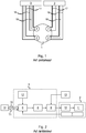
- a known aircraft brake 1 comprises four electromechanical braking actuators 2 which are grouped into two distinct groups of two electromechanical actuators 2.
- the electromechanical actuators 2 of a separate group are connected to the same centralized computer 3 located in the cargo hold of the aircraft.
- the electric motor of each electromechanical actuator 2 receives a three-phase electric supply current from the centralized computer 3 to which the electromechanical actuator 2 is connected, and each electromechanical actuator 2 transmits measurements of a servocontrol parameter to the centralized computer 3 (by example of angular position measurements of the rotor of the electric motor).
- a "high level" external setpoint is generated by external setpoint generation means 14 and is transmitted to each centralized computer 3 via a digital bus 15 (transmission symbolized by the reference T1 on the figure 2 ).
- this external setpoint is representative of a braking demand generated by a pilot of the aircraft.
- the external setpoint is transmitted to processing means 6 of the centralized computer 3.
- the processing means 6 of the centralized computer 3 then execute the control and the control of the electromechanical actuator 2 including one or more control loops.
- the electromechanical actuator 2 transmits the measurements of a servo parameter (or of several servo parameters) made by a sensor 7 to the centralized computer 3, said measurements constituting the feedback signal of the servocontrol loop.
- the output signal of the servocontrol loop is transmitted to a power module driver 8 and then to a power module 9 of the centralized computer 3 which generates the three-phase electric power supply of the electric motor 10 of the electromechanical actuator 2
- the electric motor 10 then drives the actuating member 11.
- the implementation of the servocontrol loop requires parameters stored in a memory 12 of the centralized computer 3.
- the power module 9 (which comprises, for example, an inverter ) of the centralized computer 3 is supplied by a supply unit 13 external to the centralized computer 3.
- this centralized architecture has a number of disadvantages.
- the architecture presented requires the use of at least nine electrical wires by electromechanical actuator 2: three supply wires 16 for the three phases of the electric motor (symbolized on FIG. figure 1 by a single line), four communication wires 17 (symbolized on the figure 1 by a single line) to go back to the centralized computers 3 the angular position measurements of the rotor of the electric motor 10, and two wires 18 (symbolized on the figure 1 by a single line) to supply a locking member of the electromechanical actuator 2 to implement park braking.
- the object of the invention is to reduce the size, mass, complexity and cost of a braking system.
- the generation of electric motor supply currents by the power modules positioned inside the electromechanical actuators makes it possible to reduce the number of electric wires flowing from the aircraft hold to the brake, and thus to reduce the mass and the congestion of the harnesses in which these electrical wires are integrated. Since the motor supply current no longer circulates in these harnesses, the use of common mode current filter circuits is also no longer necessary. This reduces the mass, complexity and cost of the control units.
- the communalisation of the control functions and the arrangement of communication modules in a digital network make it easy to integrate (or remove) an actuator in the architecture.
- the architecture is therefore particularly flexible and can be used on different programs, which reduces its cost.
- the invention is here implemented on an aircraft which comprises a plurality of main undercarriages each carrying a plurality of so-called “braked” wheels, that is to say a plurality of wheels equipped with a brake for braking the aircraft.
- the present description relates to a single braked wheel, but the invention applies of course in the same way to all or part of the braked wheels of the aircraft.
- a braking system architecture therefore comprises a brake 20 for braking a wheel of the aircraft, a first power supply unit 21a, a second power supply unit 21b, a first control unit 22a, a second control unit 22b and a switch network 23 (or "switch"). It is noted here that it would be perfectly possible, in place of the network switch, to use a different network interconnection element, such as a router or a hub (or “hub").
- the brake 20 comprises an actuator holder on which are mounted four electromechanical braking actuators 25a, 25b, 25c, 25d and friction members, in this case a stack of carbon disks.
- the four electromechanical actuators 25 are used to apply a braking force on the stack of carbon disks and thus exert a braking torque on the wheel which slows down the rotation of the wheel and thus brakes the aircraft when it is on the ground .
- Each electromechanical actuator 25 comprises a body attached to the actuator holder, a pusher and a locking member adapted to lock in position the pusher.
- An electric motor, a power module and a digital communication module 26 are integrated inside the body of each electromechanical actuator 25.
- the pusher is actuated by the electric motor to slide and apply the braking force to the stack of carbon discs.
- the power module makes it possible to generate an alternating supply current which circulates in three phases of the electric motor when it is necessary to actuate the pusher and thus to brake the wheel.
- the power module comprises for this purpose an inverter comprising a plurality of switches which are controlled so as to transform a DC supply voltage Vc into a three-phase AC voltage under which the power supply current of the electric motor is generated.
- the supply voltages Vc received by the power modules of the four electromechanical actuators 25 of the brake 20 come from the first power supply unit 21a and the second power supply unit 21b.
- the four electromechanical actuators 25 are grouped into a first group and a second distinct group, the first group comprising the electromechanical actuators 25a and 25b and the second group comprising the electromechanical actuators 25c and 25d.
- the first power supply unit 21a supplies the supply voltage Vc to the power modules of the electromechanical actuators 25a and 25b of the first group, while the second supply unit 21b supplies the supply voltage to the power modules of the electromechanical actuators. 25c and 25d of the second group.
- each electromechanical actuator 25 is connected by two electrical supply wires 28 to the first power supply unit 21a or the second power supply unit 21b.
- the first feed unit 21a and the second feed unit 21b are positioned in the hold, in the fuselage of the aircraft, at the top of the undercarriage.
- the power module of each electromechanical actuator 25 also uses a digital control signal Sc to control the switches of the inverter.
- the digital control signals Sc of the four electromechanical actuators 25 are generated by the first control unit 22a and by the second control unit 22b.
- each control unit 22 generates digital control signals Sc intended for two or four electromechanical actuators 25.
- the first control unit 22a and the second control unit 22b are therefore redundant, so that the loss of one of the two control units 22 does not lead to the total loss of braking.
- the first control unit 22a and the second control unit 22b are positioned in the hold, in the fuselage of the aircraft, at the top of the undercarriage.
- the distribution of the digital control signals Sc to the power modules of the four electromechanical actuators 25 is performed via the digital communication modules 26 of the four electromechanical actuators 25, each digital communication module 26 of an electromechanical actuator 25 transmitting to the power module and therefore to the inverter of the power module of said electromechanical actuator 25 the digital control signals Sc which are intended for it.
- the digital communication modules 26 of the four electromechanical actuators 25 are interconnected to form a digital network 30 (digital network is thus meant here a set of interconnected communicating devices and exchanging data in the form of digital signals).
- the digital network 30 here has a ring topology.
- the network switch 23 is thus connected to the digital communication modules 26 of two electromechanical actuators of the brake 25a and 25c, so as to constitute also one of the entities forming the closed loop of the digital ring network 30, the digital communication modules 26 of the four electromechanical actuators 25 constituting the other entities.
- Each entity (digital communication module 26 or network switch 23) of the digital network 30 is connected by four electrical communication wires 32 to two entities distinct.
- the network switch 23 manages the operation of the digital network 30 by distributing the digital control signals Sc coming from the first control unit 22a and the second control unit 22b to the digital communication modules 26 via the digital network 30.
- the network switch 23 is here positioned with the first control unit 22a and with the second control unit 22b in the same housing (which is therefore positioned in the hold, in the fuselage of the aircraft, at the top of the undercarriage).
- the transmission to the digital communication modules 26 and therefore to the power modules of the digital control signals Sc coming from the control units 22, and the supply of the power modules by the supply voltages Vc coming from the power supply units 21 require sixteen electrical wires that run from the top of the undercarriage to the brake 20, instead of the thirty-six electrical wires of the architecture of the figure 1 (or more in the case where the actuator integrates other organs: other sensors, etc.).
- the digital network 30 just described is not only used to transmit the digital control signals Sc to the power modules of the electromechanical actuators 25.
- Sm digital signals are also transmitted from the brake 20 to the control units 22 via the digital network 30 and thus via the network switch 23.
- the digital signals Sm first comprise digital measurement signals emitted by the digital communication modules 26 and coming from sensors integrated into the electromechanical actuators 25.
- the digital measurement signals are here signals for measuring the angular position of the rotors. electric motors, current measurement signals power supply of the electric motors, and force measurement signals produced by the actuating member of the electromechanical actuators 25.
- the angular position measuring signals come, for each electromechanical actuator 25, from an angular position sensor integrated in said electromechanical actuator 25.
- the current measurement signals come, for each electromechanical actuator 25, from a current sensor integrated in said electromechanical actuator 25.
- the force measurement signals come, for each electromechanical actuator 25, from a force sensor integrated in said electromechanical actuator 25.
- the angular position, current and effort measurement signals are digitized by the communication modules 26, transmitted on the digital network 30 and used by the control units 22 to generate the digital control signals Sc and to drive the electric motors.
- four electromechanical actuators 25 are electromechanical actuators 25.
- the digital signals Sm then comprise monitoring signals of the electromechanical actuators 25 emitted by the digital communication modules 26.
- the monitoring signals of the electromechanical actuators 25 are intended to provide a state of the electromechanical actuators 25 from which the control units 22 may possibly make the decision to control a maintenance operation, or to deactivate fully or partially one or more electromechanical actuators. 25.
- the upstream digital signals Sm comprise measurement signals transmitted to the electromechanical actuators by an external sensor located on the wheel or on the brake (not shown in FIG. figure 3 ).
- the external sensor is here a tachometer for measuring a speed of rotation of the wheel.
- the external sensor is integrated in the digital network 30 (it also forms a ring digital network entity). It comprises a digital interface which, like the previously mentioned digital communication modules 26, allows the external sensor to transmit the rotational speed measurements of the wheel to the control units 22 via the digital network 30.
- additional digital downlink signals Sd are transmitted from the control units 22 to the brake 20 via the digital network 30.
- the additional digital downlink signals Sd comprise, firstly, functional test command signals and electromechanical actuator sanctioning signals 25.
- the functional test order signals trigger the execution of functional tests by the electromechanical actuators 25 to establish diagnostics relating to the operation of the electromechanical actuators 25 (and, possibly, relating to the efficiency of the communications from and to the destination electromechanical actuators 25).
- the sanction order signals allow the control units 22 to "sanction" an electromechanical actuator 25 by completely or partially deactivating it, or by excluding its digital communication module 26 from the digital network 30.
- the additional downlink digital signals Sd also comprise control signals from another equipment mounted on the wheel, in this case a brake fan (not shown on the drawing). figure 3 ).
- the brake fan is integrated in the digital network 30 (it also forms a ring digital network entity). It comprises a digital interface which, like the digital communication modules 26 previously mentioned, allows the brake fan to receive the signals of control from the control units 22 via the digital network 30.
- the digital network is this time a digital star network 40.
- the network switch 23 forms a node of the digital star network 40 to which are connected all the electromechanical actuators 25 of the brake 20.
- the braking system architecture according to the second embodiment of the invention comprises, besides the four electromechanical actuators 25, the two power supply units 21, the two control units 22 and the network switch 23, a connection box 41 mounted on the actuator carrier of the brake 20.
- the four electromechanical actuators 25, the two power supply units 21, the two control units 22 and the network switch 23 are connected to the connection box 41.
- connection box 41 receives the DC supply voltages and the descending digital signals mentioned above, and distributes them to the electromechanical actuators 25 as well as to the tachometer and the brake fan.
- the connection box 41 also receives the digital uplink signals mentioned above, and distributes them to the network switch 23 which transmits them to the two control units 22.
- the locking member of each electromechanical actuator 25 is also integrated in the digital network 30 or 40.
- the locking member is then powered locally to from the supply voltage received by the electromechanical actuator 25 and coming from one of the supply units 21.
- the locking member receives control commands via the digital network 30, 40 and issues a status on the digital network 30, 40.
- each control unit 22 controls one of the four electromechanical actuators 25 is now described in more detail, and thus generates the digital control signals Sc destined for this electromechanical actuator 25.
- one of the two control units 22 and one of the four electromechanical actuators 25 form an actuating system according to a first embodiment which, in addition to the control unit 22 and the electromechanical actuator 25, comprises a digital transmission channel 50 which connects the control unit 22 and the electromechanical actuator 25.
- a digital transmission channel 50 which connects the control unit 22 and the electromechanical actuator 25.
- the digital transmission channel 50 is formed by the electrical wires which connect the control unit 22 to the network switch 23, by the network switch 23, by the connection box 41 with respect to the figure 4 and by the various elements of the digital network (electrical wires, communication modules 26 of other electromechanical actuators 25) which separate the digital communication module 26 from the electromechanical actuator 25 in question from the network switch 23.
- the control unit 22 comprises processing means 52 and a digital communication interface 53.
- the electromechanical actuator 25 comprises a communication module 26, a power module 54, an electric motor 55, a pusher 56 and measuring means 59 comprising sensors (current sensor, sensor angular position and force sensor).
- the power module 54 has a Inverter driver 57 and inverter 58.
- the electromechanical actuator 25 further comprises a non-volatile memory 60 in which stored data 61 are stored including configuration data 62 specific to the electromechanical actuator 25.
- the configuration data 62 include servo parameters 63 specific to the electromechanical actuator 25 whose role is explained below.
- the non-volatile memory 60 programmed during the manufacture of the electromechanical actuator 25, is compatible with the environmental conditions (temperature, vibrations, shocks, electromagnetic disturbances, etc.) experienced by the electromechanical actuator 25 which is mounted on an electromechanical actuator 25. brake actuator holders.
- the nonvolatile memory 60 is advantageously integrated in a semiconductor component of the digital communication module 26.
- the angular position measured by the angular position sensor of the electromechanical actuator 25 and the current measured by the current sensor of the electromechanical actuator 25 constitute servocontrol quantities of the electromechanical actuator 25.
- the measuring means 59 convert the measurements of the servo variables into digital measurement signals representative of the servo variables.
- the processing means 52 of the control unit 22 execute a servo control algorithm 67 whose executable code 65 is stored in a memory 66 of the processing means 52.
- the servocontrol algorithm 67 implements three servocontrol loops for controlling the power module 54 of the electromechanical actuator 25 via the digital channel 50: a current / torque control loop, a control loop in speed and a servo loop in position.
- Each servocontrol loop has as setpoint signal a setpoint generated by external setpoint generation means 51.
- the three servo loops are nested: the output of one servo loop is the input of another loop.
- the position control loop receives a setpoint generated by the external setpoint generation means 51.
- the position control loop transmits an instruction to the speed control loop which transmits one to the servo control loop. current / torque.
- the current / torque control loop has as its feedback signal the digital measurement signal representative of the current, and the speed and position servo loops have as their return signals the measurement signals representative of the angular position.
- the return signals are transmitted by the communication module 26 of the electromechanical actuator 25 to the control unit 22 via the digital transmission channel 50 (transmission T2 on the figure 5 ).
- the current / torque control loop produces a digital control signal of the electric motor 55 for the power module 54 (transmission T3 on the figure 5 ).
- the digital control signal comprises in this case a duty cycle for controlling switches of the inverter 58.
- the digital control signals are transmitted to the power module 54 of the electromechanical actuator 25 via the digital interface 53 of the control unit 22, the digital transmission channel 50 and the digital communication module 26 of the electromechanical actuator 25 (T3 transmission on the figure 5 ).
- the inverter driver 57 of the power module 54 then drives the inverter 58 which generates a supply current of the electric motor 55 to drive the pusher 56 of the actuator electromechanical 25 according to the instruction.
- control parameters 63 specific to the electromechanical actuator 25 which here comprise a proportional coefficient, an integral coefficient and a derivative coefficient, and a limitation in position, a limitation in speed and a current limitation of the electromechanical actuator 25.
- the processing means 52 of the control unit 22 acquire the parameters 63 servocontrol stored in the non-volatile memory 60 of the electromechanical actuator 25 and integrate them in the control loops (transmission T4 on the figure 5 ).
- the processing means 52 then have all the data necessary to execute the servocontrol algorithm 67 and the servo loops.
- any change in the design of the electromechanical actuator 25 requiring a modification of the servo parameters 63 specific to the electromechanical actuator 25 can be implemented only by storing the new servo parameters 63 in the non-volatile memory 60 of the electromechanical actuator 25, and therefore without modifying the control unit 22.
- the costs related to this change in the design of the electromechanical actuator 25 are reduced.
- the actuating system again comprises the control unit 22, the electromechanical actuator 25 and the digital transmission channel 50.
- the non-volatile memory 60 of the electromechanical actuator 25 of the actuation system according to the second embodiment is also used to set other algorithms.
- the configuration data 62 of the stored data 61 stored in the nonvolatile memory 60 comprise, in addition to the servocontrol parameters 63 of the servocontrol algorithm 67, parameters 70 of a fault detection algorithm 71, d. a trend tracking algorithm 72 and a cycle counting algorithm 73.
- the fault detection algorithm 71, the trend tracking algorithm 72 and the cycle counting algorithm 73 are stored in the memory 66 of the processing means 52 of the control unit 22. Where appropriate to execute one of these algorithms 71, 72, 73, the control unit 22 acquires the corresponding parameters 70 (transmission T5 on the figure 6 ).
- the actuating system again comprises the control unit 22, the electromechanical actuator 25 and the digital transmission channel 50.
- the non-volatile memory 60 of the electromechanical actuator 25 of the actuation system according to the third embodiment is also used to store an identifier 80 of a servocontrol algorithm to be used for the electromechanical actuator 25.
- the configuration data 62 of the stored data 61 stored in the nonvolatile memory 60 comprise an identifier 80 which enables the processing means 52 of the control unit 22 to select the servocontrol algorithm to be used from among a list of servo algorithms stored in the memory 66 of the processing means 52.
- the list of servocontrol algorithms includes a servo control algorithm 81 for an electromechanical actuator having an AC motor, a servo control algorithm 82 for an electromechanical actuator having a DC motor, a servo algorithm 83 for an electromechanical actuator having a torque motor, a servo algorithm 84 for an electromechanical actuator having a stepper motor.
- the electric motor 55 of the electromechanical actuator 25 is here an AC motor.
- the processing means 52 of the control unit 22 acquire the identifier 80 stored in the non-volatile memory 60 of the electromechanical actuator 25 (transmissions T6 and T6 'on the figure 7 ).
- the processing means 52 select and execute the servo algorithm 81 for an electromechanical actuator having an AC motor.
- the actuation system again comprises the control unit 22, an electromechanical actuator 25 and a digital transmission channel 50.
- the non-volatile memory 60 of the electromechanical actuator 25 of the actuation system is also used to store an executable code 90 of a servocontrol algorithm already parameterized of the electromechanical actuator 25.
- the processing means 52 of the control unit 22 acquire the executable code 90 of the servocontrol algorithm in the non-volatile memory (transmissions T7 on the figure 8 ).
- control unit 22 does not therefore require a prior definition of the servocontrol algorithm.
- the executable code of any type of algorithm may be stored in the nonvolatile memory 60, and not only the executable code of a servocontrol algorithm (for example, the executable code of a detection algorithm of failure and / or trend tracking algorithm and / or cycle counting algorithm).
- the non-volatile memory 60 of the electromechanical actuator 25 can be used to store configuration data comprising calibration data of the electromechanical actuator 25.
- the calibration data can be used by the control unit 22 to correct one or more command line signals of the control loops or digital measurement signals.
- the calibration data are, for example, data enabling a slope correction, an offset correction, or a correction as a function of parameters measured by the sensors of the electromechanical actuator 25.
- Storing the calibration data in the non-volatile memory 60 of the electromechanical actuator 25 makes it possible to simplify the development of the electromechanical actuator 25 during its design and manufacture, and thus to reduce the costs of design and manufacture. manufacture of the electromechanical actuator 25. In addition, the performance of the system is improved. calibrating the electromechanical actuator 25 using the calibration data.
- the nonvolatile memory 60 may contain data supplied by the control unit 22.
- the nonvolatile memory 60 is in this case accessible in read and write mode. Writing by the control unit 22.
- the stored data travels between the electromechanical actuator 25 and the control unit 22 by the transmission channel 50, whatever the direction of this path.
- the data supplied by the control unit 22 here comprises information of use of the electromechanical actuator 25, which are produced from other data stored in the non-volatile memory 60 of the electromechanical actuator 25, or which are obtained by the execution of any algorithm by the control unit 22.
- Storing the usage information relating to the electromechanical actuator 25 in its non-volatile memory 60 facilitates future maintenance operations.
- a maintenance operator will have access to the usage information of the electromechanical actuator 25 without it being necessary to configure in a particular maintenance configuration the control unit 22 or the electromechanical actuator 25.
- future repair operations A repair operator will have access to the usage information of the electromechanical actuator 25 without the need to transfer data from the control unit 22.
- the nonvolatile memory 60 may contain other information useful for the servocontrol algorithm, the monitoring, the maintenance, the production and to the delivery of the electromechanical actuator 25.
- other information one can cite for example the reference or the serial number of the electromechanical actuator 25.
- This information can in particular be used during the initialization phase of the electromechanical actuator 25.
- the storage of the stored data 61 in the non-volatile memory 60 is protected by a control tool of the redundancy check type which ensures the integrity of the data. stored 61 and detecting a corruption of these stored data.
- the transmission channel 50 consists of a fast channel and a slow channel.
- Digital data that requires fast transmission passes through the fast channel.
- These include digital control signals and digital measurement signals used in control loops.
- Digital data that does not require fast transmission passes through the slow channel.
- the stored data 61 may also be accessible for reading and / or writing by a wireless interrogation device using RFID type technology. This wireless access is particularly advantageous for performing maintenance operations on the electromechanical actuator 25.
- the communication module comprises an ASIC-type component that can be developed for several types of electromechanical actuators, which reduces the so-called "non-recurring" costs of developing these electromechanical actuators.
- the external sensor is a tachometer
- a temperature sensor of the stack of disks typically a thermocouple
- a pressure sensor typically a tire of the wheel
- a braking torque sensor typically a thermocouple
- each electromechanical actuator comprises a non-volatile memory in which the configuration data and the servo parameters are stored
- the non-volatile memories can be perfectly integrated in the control units.
Landscapes
- Engineering & Computer Science (AREA)
- Mechanical Engineering (AREA)
- General Engineering & Computer Science (AREA)
- Aviation & Aerospace Engineering (AREA)
- Signal Processing (AREA)
- Computer Networks & Wireless Communication (AREA)
- Transportation (AREA)
- Health & Medical Sciences (AREA)
- Computing Systems (AREA)
- General Health & Medical Sciences (AREA)
- Medical Informatics (AREA)
- Braking Systems And Boosters (AREA)
- Regulating Braking Force (AREA)
Applications Claiming Priority (1)
| Application Number | Priority Date | Filing Date | Title |
|---|---|---|---|
| FR1561681A FR3044296B1 (fr) | 2015-12-01 | 2015-12-01 | Architecture de systeme de freinage pour aeronoef. |
Publications (2)
| Publication Number | Publication Date |
|---|---|
| EP3176083A1 true EP3176083A1 (de) | 2017-06-07 |
| EP3176083B1 EP3176083B1 (de) | 2019-01-02 |
Family
ID=55346021
Family Applications (1)
| Application Number | Title | Priority Date | Filing Date |
|---|---|---|---|
| EP16200605.0A Active EP3176083B1 (de) | 2015-12-01 | 2016-11-24 | Aufbau eines bremssystems für ein luftfahrzeug |
Country Status (4)
| Country | Link |
|---|---|
| US (1) | US9950785B2 (de) |
| EP (1) | EP3176083B1 (de) |
| CN (1) | CN107021211B (de) |
| FR (1) | FR3044296B1 (de) |
Cited By (4)
| Publication number | Priority date | Publication date | Assignee | Title |
|---|---|---|---|---|
| FR3073203A1 (fr) * | 2017-11-08 | 2019-05-10 | Safran Landing Systems | Architecture de systeme de freinage pour aeronef |
| FR3095792A1 (fr) * | 2019-05-06 | 2020-11-13 | Safran Landing Systems | Procédé de pilotage d’un système de freinage électrique et système de freinage électrique pour aéronef |
| WO2021228696A1 (fr) * | 2020-05-12 | 2021-11-18 | Safran Landing Systems | Architecture distribuee de systeme de freinage pour aeronef |
| FR3114410A1 (fr) * | 2020-09-24 | 2022-03-25 | Safran Electronics & Defense | Architecture distribuée de système embarqué |
Families Citing this family (15)
| Publication number | Priority date | Publication date | Assignee | Title |
|---|---|---|---|---|
| KR102479850B1 (ko) * | 2017-05-15 | 2022-12-21 | 에이치엘만도 주식회사 | 전자식 주차 브레이크 |
| US10458499B2 (en) * | 2017-10-20 | 2019-10-29 | Akebono Brake Industry Co., Ltd. | Multi-caliper brake assembly per rotor |
| FR3075491B1 (fr) * | 2017-12-14 | 2019-12-20 | Safran Landing Systems | Harnais electrique |
| US10829211B2 (en) * | 2018-04-23 | 2020-11-10 | Goodrich Corporation | Local digital conversion for force and position signals for electric actuation control |
| FR3082503B1 (fr) * | 2018-06-14 | 2020-09-04 | Safran Landing Systems | Procede de freinage secours d'un aeronef |
| FR3083271B1 (fr) * | 2018-06-27 | 2020-09-04 | Safran Landing Systems | Procede de commande d'un distributeur a tiroir a trois positions |
| FR3086639B1 (fr) * | 2018-10-01 | 2020-11-20 | Safran Landing Systems | Architecture de systeme de freinage pour aeronef |
| FR3099461B1 (fr) | 2019-07-30 | 2021-08-13 | Safran Landing Systems | Dispositif de freinage d’une roue |
| JP7403332B2 (ja) * | 2020-01-28 | 2023-12-22 | 本田技研工業株式会社 | 動作装置 |
| US11472539B2 (en) | 2020-03-05 | 2022-10-18 | Goodrich Corporation | Distributed landing gear system architecture for electromechanical actuation |
| FR3115014B1 (fr) | 2020-10-08 | 2024-04-26 | Safran Landing Systems | Architecture de freinage distribuée à sûreté améliorée |
| EP4305653A1 (de) | 2021-03-12 | 2024-01-17 | Essex Industries, Inc. | Wippschalter |
| US11688568B2 (en) | 2021-03-15 | 2023-06-27 | Essex Industries, Inc. | Five-position switch |
| FR3129340B1 (fr) * | 2021-11-24 | 2024-04-26 | Hitachi Astemo France | Actionneur électromécanique comprenant une unité de commande électronique |
| US20240286590A1 (en) * | 2023-02-24 | 2024-08-29 | Goodrich Corporation | Electric brake configuration for weight and complexity reduction |
Citations (6)
| Publication number | Priority date | Publication date | Assignee | Title |
|---|---|---|---|---|
| WO2000069721A1 (en) * | 1999-05-14 | 2000-11-23 | Hydro-Aire, Inc. | Dual redundant active/active brake-by-wire architecture |
| EP1498332A1 (de) * | 2003-07-16 | 2005-01-19 | Messier Bugatti | Vorrichtung für das Verhindern eines unbeabsichtigten Bremsens angepasst an eine elektromechanischen Bremse |
| EP1739010A1 (de) * | 2005-06-27 | 2007-01-03 | Messier-Bugatti | Verteilte Architektur eines Kontrollsystems eines Flugzeug-Fahrgestells |
| US20080149436A1 (en) * | 2006-12-22 | 2008-06-26 | Griffith T Todd | System and method for an autobrake function for an aircraft electric brake system |
| EP2316701A1 (de) * | 2009-10-30 | 2011-05-04 | Messier Bugatti | Aufbau eines elektromechanischen Bremssystems |
| EP2719592A1 (de) * | 2012-10-09 | 2014-04-16 | Messier-Bugatti-Dowty | Aufbau eines elektromechanischen Bremssystems |
Family Cites Families (2)
| Publication number | Priority date | Publication date | Assignee | Title |
|---|---|---|---|---|
| FR2988373B1 (fr) * | 2012-03-21 | 2014-04-25 | Messier Bugatti Dowty | Systeme de freinage electromecanique pour aeronef |
| GB2520694A (en) * | 2013-11-27 | 2015-06-03 | Airbus Operations Ltd | Aircraft electric braking system |
-
2015
- 2015-12-01 FR FR1561681A patent/FR3044296B1/fr active Active
-
2016
- 2016-11-24 EP EP16200605.0A patent/EP3176083B1/de active Active
- 2016-11-30 US US15/365,017 patent/US9950785B2/en active Active
- 2016-11-30 CN CN201611273082.2A patent/CN107021211B/zh active Active
Patent Citations (6)
| Publication number | Priority date | Publication date | Assignee | Title |
|---|---|---|---|---|
| WO2000069721A1 (en) * | 1999-05-14 | 2000-11-23 | Hydro-Aire, Inc. | Dual redundant active/active brake-by-wire architecture |
| EP1498332A1 (de) * | 2003-07-16 | 2005-01-19 | Messier Bugatti | Vorrichtung für das Verhindern eines unbeabsichtigten Bremsens angepasst an eine elektromechanischen Bremse |
| EP1739010A1 (de) * | 2005-06-27 | 2007-01-03 | Messier-Bugatti | Verteilte Architektur eines Kontrollsystems eines Flugzeug-Fahrgestells |
| US20080149436A1 (en) * | 2006-12-22 | 2008-06-26 | Griffith T Todd | System and method for an autobrake function for an aircraft electric brake system |
| EP2316701A1 (de) * | 2009-10-30 | 2011-05-04 | Messier Bugatti | Aufbau eines elektromechanischen Bremssystems |
| EP2719592A1 (de) * | 2012-10-09 | 2014-04-16 | Messier-Bugatti-Dowty | Aufbau eines elektromechanischen Bremssystems |
Cited By (9)
| Publication number | Priority date | Publication date | Assignee | Title |
|---|---|---|---|---|
| FR3073203A1 (fr) * | 2017-11-08 | 2019-05-10 | Safran Landing Systems | Architecture de systeme de freinage pour aeronef |
| EP3483063A1 (de) * | 2017-11-08 | 2019-05-15 | Safran Landing Systems | Aufbau eines bremssystems für ein luftfahrzeug |
| US10793121B2 (en) | 2017-11-08 | 2020-10-06 | Safran Landing Systems | Architecture for an aircraft braking system |
| FR3095792A1 (fr) * | 2019-05-06 | 2020-11-13 | Safran Landing Systems | Procédé de pilotage d’un système de freinage électrique et système de freinage électrique pour aéronef |
| EP3736185A3 (de) * | 2019-05-06 | 2020-11-25 | Safran Landing Systems | Steuerverfahren eines elektrischen bremssystems, und elektrisches bremssystem für luftfahrzeug |
| US11447109B2 (en) | 2019-05-06 | 2022-09-20 | Safran Landing Systems | Control method for an electrical braking system and electrical braking system for aircraft |
| WO2021228696A1 (fr) * | 2020-05-12 | 2021-11-18 | Safran Landing Systems | Architecture distribuee de systeme de freinage pour aeronef |
| FR3110137A1 (fr) * | 2020-05-12 | 2021-11-19 | Safran Landing Systems | Architecture distribuée de système de freinage pour aéronef |
| FR3114410A1 (fr) * | 2020-09-24 | 2022-03-25 | Safran Electronics & Defense | Architecture distribuée de système embarqué |
Also Published As
| Publication number | Publication date |
|---|---|
| CN107021211A (zh) | 2017-08-08 |
| FR3044296B1 (fr) | 2017-12-29 |
| CN107021211B (zh) | 2019-08-20 |
| US20170152027A1 (en) | 2017-06-01 |
| FR3044296A1 (fr) | 2017-06-02 |
| US9950785B2 (en) | 2018-04-24 |
| EP3176083B1 (de) | 2019-01-02 |
Similar Documents
| Publication | Publication Date | Title |
|---|---|---|
| EP3176083B1 (de) | Aufbau eines bremssystems für ein luftfahrzeug | |
| EP3176655B1 (de) | Betätigungssystem für luftfahrzeug | |
| EP1739010B1 (de) | Verteilte Architektur eines Kontrollsystems eines Flugzeug-Fahrgestells | |
| EP3339170B1 (de) | Aufbau eines bremssystems für ein luftfahrzeug | |
| WO2010103234A1 (fr) | Système de commande d'aéronef à architecture modulaire intégrée | |
| FR2943036A1 (fr) | Systeme distribue de commande de vol implemente selon une architecture avionique modulaire integree. | |
| FR3072924B1 (fr) | Equipement electrique destine a etre relie a un actionneur electromecanique de freinage et a un actionneur electromecanique d'entrainement | |
| FR2899040A1 (fr) | Systeme de puissance comportant plusieurs machines synchrones autopilotees de facon synchronisee par un convertisseur et procede de commande d'un tel systeme | |
| EP2293429A2 (de) | Gesicherte Vorrichtung zur Überwachung und Steuerung für ein Flugzeugsteuerung-stellglied | |
| EP3483063B1 (de) | Aufbau eines bremssystems für ein luftfahrzeug | |
| EP3505402B1 (de) | Elektrisches seilgurtzeug | |
| EP2563654B1 (de) | Betätigung der flügel eines nicht stromlinienförmigen luftgebläses | |
| EP3718841A1 (de) | Bremssystem eines luftfahrzeugrads, das gemäss normal-modus oder rto-modus eingestellt werden kann | |
| FR3110137A1 (fr) | Architecture distribuée de système de freinage pour aéronef | |
| FR3058278A1 (fr) | Systeme pour l'alimentation d'actionneurs electriques embarques dans un aeronef | |
| EP4103469B1 (de) | Verfahren zur steuerung eines flugzeugrollsystems |
Legal Events
| Date | Code | Title | Description |
|---|---|---|---|
| AK | Designated contracting states |
Kind code of ref document: A1 Designated state(s): AL AT BE BG CH CY CZ DE DK EE ES FI FR GB GR HR HU IE IS IT LI LT LU LV MC MK MT NL NO PL PT RO RS SE SI SK SM TR |
|
| AX | Request for extension of the european patent |
Extension state: BA ME |
|
| PUAI | Public reference made under article 153(3) epc to a published international application that has entered the european phase |
Free format text: ORIGINAL CODE: 0009012 |
|
| STAA | Information on the status of an ep patent application or granted ep patent |
Free format text: STATUS: THE APPLICATION HAS BEEN PUBLISHED |
|
| STAA | Information on the status of an ep patent application or granted ep patent |
Free format text: STATUS: REQUEST FOR EXAMINATION WAS MADE |
|
| 17P | Request for examination filed |
Effective date: 20171130 |
|
| RBV | Designated contracting states (corrected) |
Designated state(s): AL AT BE BG CH CY CZ DE DK EE ES FI FR GB GR HR HU IE IS IT LI LT LU LV MC MK MT NL NO PL PT RO RS SE SI SK SM TR |
|
| RIC1 | Information provided on ipc code assigned before grant |
Ipc: B60T 13/74 20060101ALN20180319BHEP Ipc: B64C 25/42 20060101AFI20180319BHEP Ipc: B64C 25/44 20060101ALI20180319BHEP |
|
| GRAP | Despatch of communication of intention to grant a patent |
Free format text: ORIGINAL CODE: EPIDOSNIGR1 |
|
| STAA | Information on the status of an ep patent application or granted ep patent |
Free format text: STATUS: GRANT OF PATENT IS INTENDED |
|
| RAP1 | Party data changed (applicant data changed or rights of an application transferred) |
Owner name: SAFRAN LANDING SYSTEM |
|
| INTG | Intention to grant announced |
Effective date: 20180718 |
|
| GRAS | Grant fee paid |
Free format text: ORIGINAL CODE: EPIDOSNIGR3 |
|
| GRAA | (expected) grant |
Free format text: ORIGINAL CODE: 0009210 |
|
| STAA | Information on the status of an ep patent application or granted ep patent |
Free format text: STATUS: THE PATENT HAS BEEN GRANTED |
|
| AK | Designated contracting states |
Kind code of ref document: B1 Designated state(s): AL AT BE BG CH CY CZ DE DK EE ES FI FR GB GR HR HU IE IS IT LI LT LU LV MC MK MT NL NO PL PT RO RS SE SI SK SM TR |
|
| REG | Reference to a national code |
Ref country code: GB Ref legal event code: FG4D Free format text: NOT ENGLISH |
|
| REG | Reference to a national code |
Ref country code: CH Ref legal event code: EP Ref country code: AT Ref legal event code: REF Ref document number: 1084027 Country of ref document: AT Kind code of ref document: T Effective date: 20190115 |
|
| REG | Reference to a national code |
Ref country code: IE Ref legal event code: FG4D Free format text: LANGUAGE OF EP DOCUMENT: FRENCH |
|
| REG | Reference to a national code |
Ref country code: DE Ref legal event code: R096 Ref document number: 602016008937 Country of ref document: DE |
|
| REG | Reference to a national code |
Ref country code: NL Ref legal event code: MP Effective date: 20190102 |
|
| REG | Reference to a national code |
Ref country code: LT Ref legal event code: MG4D |
|
| REG | Reference to a national code |
Ref country code: AT Ref legal event code: MK05 Ref document number: 1084027 Country of ref document: AT Kind code of ref document: T Effective date: 20190102 |
|
| PG25 | Lapsed in a contracting state [announced via postgrant information from national office to epo] |
Ref country code: NL Free format text: LAPSE BECAUSE OF FAILURE TO SUBMIT A TRANSLATION OF THE DESCRIPTION OR TO PAY THE FEE WITHIN THE PRESCRIBED TIME-LIMIT Effective date: 20190102 |
|
| PG25 | Lapsed in a contracting state [announced via postgrant information from national office to epo] |
Ref country code: LT Free format text: LAPSE BECAUSE OF FAILURE TO SUBMIT A TRANSLATION OF THE DESCRIPTION OR TO PAY THE FEE WITHIN THE PRESCRIBED TIME-LIMIT Effective date: 20190102 Ref country code: SE Free format text: LAPSE BECAUSE OF FAILURE TO SUBMIT A TRANSLATION OF THE DESCRIPTION OR TO PAY THE FEE WITHIN THE PRESCRIBED TIME-LIMIT Effective date: 20190102 Ref country code: FI Free format text: LAPSE BECAUSE OF FAILURE TO SUBMIT A TRANSLATION OF THE DESCRIPTION OR TO PAY THE FEE WITHIN THE PRESCRIBED TIME-LIMIT Effective date: 20190102 Ref country code: PT Free format text: LAPSE BECAUSE OF FAILURE TO SUBMIT A TRANSLATION OF THE DESCRIPTION OR TO PAY THE FEE WITHIN THE PRESCRIBED TIME-LIMIT Effective date: 20190502 Ref country code: NO Free format text: LAPSE BECAUSE OF FAILURE TO SUBMIT A TRANSLATION OF THE DESCRIPTION OR TO PAY THE FEE WITHIN THE PRESCRIBED TIME-LIMIT Effective date: 20190402 Ref country code: ES Free format text: LAPSE BECAUSE OF FAILURE TO SUBMIT A TRANSLATION OF THE DESCRIPTION OR TO PAY THE FEE WITHIN THE PRESCRIBED TIME-LIMIT Effective date: 20190102 Ref country code: PL Free format text: LAPSE BECAUSE OF FAILURE TO SUBMIT A TRANSLATION OF THE DESCRIPTION OR TO PAY THE FEE WITHIN THE PRESCRIBED TIME-LIMIT Effective date: 20190102 |
|
| PG25 | Lapsed in a contracting state [announced via postgrant information from national office to epo] |
Ref country code: IS Free format text: LAPSE BECAUSE OF FAILURE TO SUBMIT A TRANSLATION OF THE DESCRIPTION OR TO PAY THE FEE WITHIN THE PRESCRIBED TIME-LIMIT Effective date: 20190502 Ref country code: LV Free format text: LAPSE BECAUSE OF FAILURE TO SUBMIT A TRANSLATION OF THE DESCRIPTION OR TO PAY THE FEE WITHIN THE PRESCRIBED TIME-LIMIT Effective date: 20190102 Ref country code: GR Free format text: LAPSE BECAUSE OF FAILURE TO SUBMIT A TRANSLATION OF THE DESCRIPTION OR TO PAY THE FEE WITHIN THE PRESCRIBED TIME-LIMIT Effective date: 20190403 Ref country code: HR Free format text: LAPSE BECAUSE OF FAILURE TO SUBMIT A TRANSLATION OF THE DESCRIPTION OR TO PAY THE FEE WITHIN THE PRESCRIBED TIME-LIMIT Effective date: 20190102 Ref country code: RS Free format text: LAPSE BECAUSE OF FAILURE TO SUBMIT A TRANSLATION OF THE DESCRIPTION OR TO PAY THE FEE WITHIN THE PRESCRIBED TIME-LIMIT Effective date: 20190102 Ref country code: BG Free format text: LAPSE BECAUSE OF FAILURE TO SUBMIT A TRANSLATION OF THE DESCRIPTION OR TO PAY THE FEE WITHIN THE PRESCRIBED TIME-LIMIT Effective date: 20190402 |
|
| REG | Reference to a national code |
Ref country code: DE Ref legal event code: R097 Ref document number: 602016008937 Country of ref document: DE |
|
| PG25 | Lapsed in a contracting state [announced via postgrant information from national office to epo] |
Ref country code: AL Free format text: LAPSE BECAUSE OF FAILURE TO SUBMIT A TRANSLATION OF THE DESCRIPTION OR TO PAY THE FEE WITHIN THE PRESCRIBED TIME-LIMIT Effective date: 20190102 Ref country code: CZ Free format text: LAPSE BECAUSE OF FAILURE TO SUBMIT A TRANSLATION OF THE DESCRIPTION OR TO PAY THE FEE WITHIN THE PRESCRIBED TIME-LIMIT Effective date: 20190102 Ref country code: AT Free format text: LAPSE BECAUSE OF FAILURE TO SUBMIT A TRANSLATION OF THE DESCRIPTION OR TO PAY THE FEE WITHIN THE PRESCRIBED TIME-LIMIT Effective date: 20190102 Ref country code: RO Free format text: LAPSE BECAUSE OF FAILURE TO SUBMIT A TRANSLATION OF THE DESCRIPTION OR TO PAY THE FEE WITHIN THE PRESCRIBED TIME-LIMIT Effective date: 20190102 Ref country code: EE Free format text: LAPSE BECAUSE OF FAILURE TO SUBMIT A TRANSLATION OF THE DESCRIPTION OR TO PAY THE FEE WITHIN THE PRESCRIBED TIME-LIMIT Effective date: 20190102 Ref country code: IT Free format text: LAPSE BECAUSE OF FAILURE TO SUBMIT A TRANSLATION OF THE DESCRIPTION OR TO PAY THE FEE WITHIN THE PRESCRIBED TIME-LIMIT Effective date: 20190102 Ref country code: DK Free format text: LAPSE BECAUSE OF FAILURE TO SUBMIT A TRANSLATION OF THE DESCRIPTION OR TO PAY THE FEE WITHIN THE PRESCRIBED TIME-LIMIT Effective date: 20190102 Ref country code: SK Free format text: LAPSE BECAUSE OF FAILURE TO SUBMIT A TRANSLATION OF THE DESCRIPTION OR TO PAY THE FEE WITHIN THE PRESCRIBED TIME-LIMIT Effective date: 20190102 |
|
| PLBE | No opposition filed within time limit |
Free format text: ORIGINAL CODE: 0009261 |
|
| STAA | Information on the status of an ep patent application or granted ep patent |
Free format text: STATUS: NO OPPOSITION FILED WITHIN TIME LIMIT |
|
| PG25 | Lapsed in a contracting state [announced via postgrant information from national office to epo] |
Ref country code: SM Free format text: LAPSE BECAUSE OF FAILURE TO SUBMIT A TRANSLATION OF THE DESCRIPTION OR TO PAY THE FEE WITHIN THE PRESCRIBED TIME-LIMIT Effective date: 20190102 |
|
| 26N | No opposition filed |
Effective date: 20191003 |
|
| PG25 | Lapsed in a contracting state [announced via postgrant information from national office to epo] |
Ref country code: SI Free format text: LAPSE BECAUSE OF FAILURE TO SUBMIT A TRANSLATION OF THE DESCRIPTION OR TO PAY THE FEE WITHIN THE PRESCRIBED TIME-LIMIT Effective date: 20190102 |
|
| PG25 | Lapsed in a contracting state [announced via postgrant information from national office to epo] |
Ref country code: TR Free format text: LAPSE BECAUSE OF FAILURE TO SUBMIT A TRANSLATION OF THE DESCRIPTION OR TO PAY THE FEE WITHIN THE PRESCRIBED TIME-LIMIT Effective date: 20190102 |
|
| REG | Reference to a national code |
Ref country code: CH Ref legal event code: PL |
|
| PG25 | Lapsed in a contracting state [announced via postgrant information from national office to epo] |
Ref country code: LI Free format text: LAPSE BECAUSE OF NON-PAYMENT OF DUE FEES Effective date: 20191130 Ref country code: CH Free format text: LAPSE BECAUSE OF NON-PAYMENT OF DUE FEES Effective date: 20191130 Ref country code: MC Free format text: LAPSE BECAUSE OF FAILURE TO SUBMIT A TRANSLATION OF THE DESCRIPTION OR TO PAY THE FEE WITHIN THE PRESCRIBED TIME-LIMIT Effective date: 20190102 Ref country code: LU Free format text: LAPSE BECAUSE OF NON-PAYMENT OF DUE FEES Effective date: 20191124 |
|
| REG | Reference to a national code |
Ref country code: BE Ref legal event code: MM Effective date: 20191130 |
|
| PG25 | Lapsed in a contracting state [announced via postgrant information from national office to epo] |
Ref country code: IE Free format text: LAPSE BECAUSE OF NON-PAYMENT OF DUE FEES Effective date: 20191124 |
|
| PG25 | Lapsed in a contracting state [announced via postgrant information from national office to epo] |
Ref country code: BE Free format text: LAPSE BECAUSE OF NON-PAYMENT OF DUE FEES Effective date: 20191130 |
|
| PG25 | Lapsed in a contracting state [announced via postgrant information from national office to epo] |
Ref country code: CY Free format text: LAPSE BECAUSE OF FAILURE TO SUBMIT A TRANSLATION OF THE DESCRIPTION OR TO PAY THE FEE WITHIN THE PRESCRIBED TIME-LIMIT Effective date: 20190102 |
|
| PG25 | Lapsed in a contracting state [announced via postgrant information from national office to epo] |
Ref country code: MT Free format text: LAPSE BECAUSE OF FAILURE TO SUBMIT A TRANSLATION OF THE DESCRIPTION OR TO PAY THE FEE WITHIN THE PRESCRIBED TIME-LIMIT Effective date: 20190102 Ref country code: HU Free format text: LAPSE BECAUSE OF FAILURE TO SUBMIT A TRANSLATION OF THE DESCRIPTION OR TO PAY THE FEE WITHIN THE PRESCRIBED TIME-LIMIT; INVALID AB INITIO Effective date: 20161124 |
|
| PG25 | Lapsed in a contracting state [announced via postgrant information from national office to epo] |
Ref country code: MK Free format text: LAPSE BECAUSE OF FAILURE TO SUBMIT A TRANSLATION OF THE DESCRIPTION OR TO PAY THE FEE WITHIN THE PRESCRIBED TIME-LIMIT Effective date: 20190102 |
|
| PGFP | Annual fee paid to national office [announced via postgrant information from national office to epo] |
Ref country code: GB Payment date: 20231019 Year of fee payment: 8 |
|
| PGFP | Annual fee paid to national office [announced via postgrant information from national office to epo] |
Ref country code: FR Payment date: 20231019 Year of fee payment: 8 Ref country code: DE Payment date: 20231019 Year of fee payment: 8 |