EP3176068A1 - Vessel characteristic estimation device and automatic steering device - Google Patents
Vessel characteristic estimation device and automatic steering device Download PDFInfo
- Publication number
- EP3176068A1 EP3176068A1 EP15826886.2A EP15826886A EP3176068A1 EP 3176068 A1 EP3176068 A1 EP 3176068A1 EP 15826886 A EP15826886 A EP 15826886A EP 3176068 A1 EP3176068 A1 EP 3176068A1
- Authority
- EP
- European Patent Office
- Prior art keywords
- ship
- data
- rotational speed
- velocity vector
- wind
- Prior art date
- Legal status (The legal status is an assumption and is not a legal conclusion. Google has not performed a legal analysis and makes no representation as to the accuracy of the status listed.)
- Granted
Links
Images















Classifications
-
- B—PERFORMING OPERATIONS; TRANSPORTING
- B63—SHIPS OR OTHER WATERBORNE VESSELS; RELATED EQUIPMENT
- B63H—MARINE PROPULSION OR STEERING
- B63H25/00—Steering; Slowing-down otherwise than by use of propulsive elements; Dynamic anchoring, i.e. positioning vessels by means of main or auxiliary propulsive elements
- B63H25/02—Initiating means for steering, for slowing down, otherwise than by use of propulsive elements, or for dynamic anchoring
- B63H25/04—Initiating means for steering, for slowing down, otherwise than by use of propulsive elements, or for dynamic anchoring automatic, e.g. reacting to compass
-
- B—PERFORMING OPERATIONS; TRANSPORTING
- B63—SHIPS OR OTHER WATERBORNE VESSELS; RELATED EQUIPMENT
- B63B—SHIPS OR OTHER WATERBORNE VESSELS; EQUIPMENT FOR SHIPPING
- B63B49/00—Arrangements of nautical instruments or navigational aids
-
- B—PERFORMING OPERATIONS; TRANSPORTING
- B63—SHIPS OR OTHER WATERBORNE VESSELS; RELATED EQUIPMENT
- B63B—SHIPS OR OTHER WATERBORNE VESSELS; EQUIPMENT FOR SHIPPING
- B63B79/00—Monitoring properties or operating parameters of vessels in operation
- B63B79/10—Monitoring properties or operating parameters of vessels in operation using sensors, e.g. pressure sensors, strain gauges or accelerometers
- B63B79/15—Monitoring properties or operating parameters of vessels in operation using sensors, e.g. pressure sensors, strain gauges or accelerometers for monitoring environmental variables, e.g. wave height or weather data
-
- B—PERFORMING OPERATIONS; TRANSPORTING
- B63—SHIPS OR OTHER WATERBORNE VESSELS; RELATED EQUIPMENT
- B63B—SHIPS OR OTHER WATERBORNE VESSELS; EQUIPMENT FOR SHIPPING
- B63B79/00—Monitoring properties or operating parameters of vessels in operation
- B63B79/30—Monitoring properties or operating parameters of vessels in operation for diagnosing, testing or predicting the integrity or performance of vessels
-
- B—PERFORMING OPERATIONS; TRANSPORTING
- B63—SHIPS OR OTHER WATERBORNE VESSELS; RELATED EQUIPMENT
- B63B—SHIPS OR OTHER WATERBORNE VESSELS; EQUIPMENT FOR SHIPPING
- B63B79/00—Monitoring properties or operating parameters of vessels in operation
- B63B79/40—Monitoring properties or operating parameters of vessels in operation for controlling the operation of vessels, e.g. monitoring their speed, routing or maintenance schedules
-
- B—PERFORMING OPERATIONS; TRANSPORTING
- B63—SHIPS OR OTHER WATERBORNE VESSELS; RELATED EQUIPMENT
- B63H—MARINE PROPULSION OR STEERING
- B63H25/00—Steering; Slowing-down otherwise than by use of propulsive elements; Dynamic anchoring, i.e. positioning vessels by means of main or auxiliary propulsive elements
- B63H25/06—Steering by rudders
- B63H25/38—Rudders
- B63H25/382—Rudders movable otherwise than for steering purposes; Changing geometry
-
- G—PHYSICS
- G01—MEASURING; TESTING
- G01P—MEASURING LINEAR OR ANGULAR SPEED, ACCELERATION, DECELERATION, OR SHOCK; INDICATING PRESENCE, ABSENCE, OR DIRECTION, OF MOVEMENT
- G01P3/00—Measuring linear or angular speed; Measuring differences of linear or angular speeds
-
- G—PHYSICS
- G01—MEASURING; TESTING
- G01P—MEASURING LINEAR OR ANGULAR SPEED, ACCELERATION, DECELERATION, OR SHOCK; INDICATING PRESENCE, ABSENCE, OR DIRECTION, OF MOVEMENT
- G01P5/00—Measuring speed of fluids, e.g. of air stream; Measuring speed of bodies relative to fluids, e.g. of ship, of aircraft
-
- G—PHYSICS
- G01—MEASURING; TESTING
- G01P—MEASURING LINEAR OR ANGULAR SPEED, ACCELERATION, DECELERATION, OR SHOCK; INDICATING PRESENCE, ABSENCE, OR DIRECTION, OF MOVEMENT
- G01P5/00—Measuring speed of fluids, e.g. of air stream; Measuring speed of bodies relative to fluids, e.g. of ship, of aircraft
- G01P5/02—Measuring speed of fluids, e.g. of air stream; Measuring speed of bodies relative to fluids, e.g. of ship, of aircraft by measuring forces exerted by the fluid on solid bodies, e.g. anemometer
- G01P5/06—Measuring speed of fluids, e.g. of air stream; Measuring speed of bodies relative to fluids, e.g. of ship, of aircraft by measuring forces exerted by the fluid on solid bodies, e.g. anemometer using rotation of vanes
-
- G—PHYSICS
- G05—CONTROLLING; REGULATING
- G05D—SYSTEMS FOR CONTROLLING OR REGULATING NON-ELECTRIC VARIABLES
- G05D1/00—Control of position, course, altitude or attitude of land, water, air or space vehicles, e.g. using automatic pilots
- G05D1/02—Control of position or course in two dimensions
- G05D1/0206—Control of position or course in two dimensions specially adapted to water vehicles
-
- B—PERFORMING OPERATIONS; TRANSPORTING
- B63—SHIPS OR OTHER WATERBORNE VESSELS; RELATED EQUIPMENT
- B63B—SHIPS OR OTHER WATERBORNE VESSELS; EQUIPMENT FOR SHIPPING
- B63B2213/00—Navigational aids and use thereof, not otherwise provided for in this class
- B63B2213/02—Navigational aids and use thereof, not otherwise provided for in this class using satellite radio beacon positioning systems, e.g. the Global Positioning System GPS
-
- B—PERFORMING OPERATIONS; TRANSPORTING
- B63—SHIPS OR OTHER WATERBORNE VESSELS; RELATED EQUIPMENT
- B63H—MARINE PROPULSION OR STEERING
- B63H25/00—Steering; Slowing-down otherwise than by use of propulsive elements; Dynamic anchoring, i.e. positioning vessels by means of main or auxiliary propulsive elements
- B63H25/02—Initiating means for steering, for slowing down, otherwise than by use of propulsive elements, or for dynamic anchoring
- B63H25/04—Initiating means for steering, for slowing down, otherwise than by use of propulsive elements, or for dynamic anchoring automatic, e.g. reacting to compass
- B63H2025/045—Initiating means for steering, for slowing down, otherwise than by use of propulsive elements, or for dynamic anchoring automatic, e.g. reacting to compass making use of satellite radio beacon positioning systems, e.g. the Global Positioning System [GPS]
Definitions
- This disclosure relates to a ship characteristic estimating device which estimates characteristics of a ship, and an autopilot system which includes the ship characteristic estimating device.
- Patent Document 1 discloses a system capable of diagnosing a state of a ship based on operational information (temperature, pressure, rotational speed etc. of a propulsion system of the ship) detected by various sensors attached to the ship.
- Patent Document 1 JP2002-316692A
- examples of the parameters which influence the log velocity of the ship include a rotational speed of a propeller of the ship and wind force against the ship.
- examples of the parameters which influence the log velocity of the ship include a rotational speed of a propeller of the ship and wind force against the ship.
- experiments need to be conducted while the other parameters which influence the log velocity of the ship (wind force etc.) are kept stable, which is extremely troublesome. This is similar in a case of grasping a relationship between the wind force against the ship and the log velocity of the ship caused by the wind force.
- This disclosure is to solve the above situations and aims to easily grasp a relationship of parameter values which influence a log velocity of a ship, with the log velocity of the ship caused by the parameters.
- Fig. 1 is a block diagram illustrating a configuration of an estimating apparatus 1 according to one embodiment of this disclosure.
- the estimating apparatus 1 is equipped in a first ship (ship) which travels on water.
- the estimating apparatus 1 includes a surface current estimating device 8 and a wind force characteristic estimating device 9 (ship characteristic estimating device).
- the surface current estimating device 8 is configured to estimate a direction and magnitude of a surface current at a position of the first ship, in other words, a velocity vector of the surface current at the first ship position.
- the wind force characteristic estimating device 9 is configured to estimate wind force characteristics of the first ship.
- a configuration of the surface current estimating device 8 and a configuration of the wind force characteristic estimating device 9 are described in this order.
- the surface current is a flow within a depth range which is about a range from a water surface to a bottom of the first ship.
- the wind force characteristics are characteristics indicating how a moving speed of the first ship changes on static water due to a bearing and magnitude of the wind force against the first ship.
- the surface current estimating device 8 automatically obtains particular parameters (in this embodiment, a rotational speed of a propeller of the first ship, a true wind speed in a bow direction, and a true wind speed in a starboard direction) at every particular timing, and calculates a surface current velocity (surface current velocity vector) at the first ship position for every condition defined by a combination of values of the respective parameters.
- the surface current estimating device 8 includes a GPS signal receiver 2, a propeller speed detector 3, a vane anemometer 4, one or some of components constituting a calculator 10 (e.g., a ground velocity calculating module 11, an estimator 12, a surface current calculating module 13, and a coupling coefficient updating module 14), and a display unit 5.
- the GPS signal receiver 2 is provided as a GNSS signal receiver configured to receive GPS signals as navigation signals (GNSS signals) which are transmitted from navigation satellites (not illustrated).
- the GPS signal receiver 2 includes a GPS antenna, for example.
- the GPS signals received by the GPS signal receiver 2 i.e., positional information of the first ship
- the GPS signal receiver 2 is used as the GNSS signal receiver; however, without limiting to this, a receiver used in another GNSS system may be used.
- GNSS is an abbreviation of Global Navigation Satellite Systems. This GNSS is a collective name for "GPS” administrated by the United States of America, “GALILEO” administrated by the European Union, “GLONASS” administrated by Russia, etc.
- the propeller speed detector 3 detects a rotational speed per unit time of the propeller configured to produce a propulsion force (thrust) of the first ship, and includes a sensor capable of detecting a rotational speed, for example. The rotational speed detected by the propeller speed detector 3 is notified to the calculator 10.
- the vane anemometer 4 measures, as information of a wind direction and speed, the true wind speed in the bow direction and the true wind speed in the starboard direction.
- the vane anemometer 4 is disposed in the first ship where the surface current estimating device 8 according to this embodiment is equipped, at a location with no obstacle in its surrounding which blocks wind.
- the true wind speed in the bow direction and the true wind speed in the starboard direction measured by the vane anemometer 4 are notified to the calculator 10.
- the calculator 10 is configured to estimate a surface current at the first ship position (target location) at every particular timing, based on the various information notified by the GPS signal receiver 2, the propeller speed detector 3, and the vane anemometer 4.
- the calculator 10 includes the ground velocity calculating module 11, the estimator 12, the surface current calculating module 13, and the coupling coefficient updating module 14. Note that, although it is described later in detail, the calculator 10 is configured to also estimate the wind force characteristics based on the parameters outputted from a data output unit 6.
- the ground velocity calculating module 11 calculates a ground velocity (ground velocity vector) of the first ship based on the positional information of the first ship and the acquired time point of the first ship positional information, which are notified from the GPS signal receiver 2. Specifically, the ground velocity calculating module 11 calculates the ground velocity of the first ship based on first ship positions of at least two timings and acquired time points of the positional information of the respective first ship positions. The ground velocity calculating module 11 notifies the ground velocity calculated as above, to the surface current calculating module 13 and the coupling coefficient updating module 14.
- the estimator 12 is configured to estimate a log velocity of the first ship.
- the estimator 12 receives the rotational speed of the propeller of the first ship, which is detected by the propeller speed detector 3, and the true wind speed in the bow direction and the true wind speed in the starboard direction, which are measured by the vane anemometer.
- the estimator 12 outputs to the surface current calculating module 13 a value corresponding to a condition defined by a combination of these input values (a condition defined by a combination of a certain rotational speed, a certain true wind speed in the bow direction, and a certain true wind speed in the starboard direction) as the log velocity (log velocity vector, which is a log velocity in the bow direction and a log velocity in the starboard direction in this embodiment).
- the estimator 12 also receives the parameter data outputted from the data output unit 6, and the estimator 12 outputs a value corresponding thereto to an image generating module 15 as the log velocity.
- Fig. 2 is a schematic view illustrating one example of a configuration of the estimator 12.
- the estimator 12 is configured using a commonly-known neural network.
- the estimator 12 includes a plurality of input units U IN_1 , U IN_2 and U IN_3 structuring an input layer, a plurality of middle units U MID_1 , U MID_2 and U MID_3 structuring a hidden layer, and a plurality of output units U OUT_1 and U OUT_2 structuring an output layer.
- the configuration of the estimator 12 illustrated in Fig. 2 is merely an example, and the number of units in each layer, the number of hidden layers are not limited to those illustrated in Fig. 2 .
- each of those input values is multiplied by a coupling coefficient W I,M and outputted to the middle units U MID_1 , U MID 2 and U MID_3 of the hidden layer.
- Each of the middle units U MID_1 , U MID 2 and U MID_3 of the hidden layer adds up the inputted values to obtain a total, multiplies by a coupling coefficient W M,O a value obtained based on the total value, and outputs it to the output units U OUT_1 and U OUT_2 .
- Each of the output units U OUT_1 and U OUT_2 adds up the inputted values to obtain a total, and outputs, as a second output value, a value obtained based on the total value, to the surface current calculating module 13 and the coupling coefficient updating module 14.
- the values inputted into the estimator 12 are not necessarily the values of the parameter themselves, such as the rotational speed of the propeller, etc., and they may be numerical values which are in a one-to-one relationship with those parameters, respectively (e.g., a voltage value which changes in proportion to the rotational speed), etc.
- a suitable initial value is set for each coupling coefficient W.
- the coupling coefficient W is updated by the coupling coefficient updating module 14 as needed.
- the coupling coefficient W is updated by the coupling coefficient updating module 14 to reduce an error of each second output value outputted from the estimator 12 with respect to the ground velocity (teaching signal) calculated by the ground velocity calculating module 11.
- the second output value outputted from the estimator 12 although described later in detail, is converged to the log velocity of the first ship every time the coupling coefficient W is updated.
- the surface current calculating module 13 calculates a surface current velocity (surface current velocity vector) that is a velocity of a surface current, based on the second output values as the log velocity outputted from the estimator 12 and the ground velocity calculated by the ground velocity calculating module 11. For example, the surface current calculating module 13 calculates the surface current velocity by subtracting the log velocity from the ground velocity.
- Fig. 3 is a vector diagram illustrating a relationship among the ground velocity vector V G , the log velocity vector V W , and the surface current velocity vector V T .
- the ground velocity V G is a velocity over a ground surface
- the log velocity V W is a velocity over a water surface (sea surface).
- the surface current is a water current in a surface zone of the sea. Therefore, the relationship among the ground velocity vector V G , the log velocity vector V W , and the surface current velocity vector V T may be expressed as illustrated in Fig. 3 .
- the surface current calculating module 13 subtracts the log velocity V W from the ground velocity V G as described above to calculate the surface current velocity V T .
- the coupling coefficient updating module 14 updates each coupling coefficient W of the estimator 12 to reduce the error of each second output value from the estimator 12 with respect to the ground velocity (teaching signal) calculated by the ground velocity calculating module 11.
- the coupling coefficient updating module 14 updates the coupling coefficient W by using a backpropagation method, for example.
- the display unit 5 displays the direction and magnitude of the surface current calculated by the surface current calculating module 13, which enables a user to learn the velocity of the surface current at the first ship position.
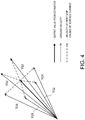
- Fig. 4 is a view illustrating how each second output value from the estimator 12 converges to the log velocity every time the coupling coefficient W of the estimator 12 is updated.
- each coupling coefficient W stored in the estimator 12 is updated by the coupling coefficient updating module 14 to reduce the error of the output value, which is outputted from the estimator 12 as needed, with respect to the ground velocity as the teaching signal calculated as needed.
- the surface current varies in magnitude and direction depending on a marine area, time, a meteorological condition, etc.
- the ground velocity is considered to contain components of surface current velocities of various magnitudes and directions. Therefore, by averaging these components (averaging V G1 to V G6 in the case of Fig. 4 ), the surface current velocity components cancel out each other and the log velocity component remains.
- the coupling coefficient W of the estimator 12 is updated to reduce the error of the second output value of the estimator 12 with respect to the ground velocity as described above, an influence of the surface current velocity components contained in the ground velocity gradually becomes smaller; therefore, the second output value of the estimator 12 converges to the log velocity.
- the second output value from the estimator 12 can be estimated as the log velocity.
- the rotational speed is detected by the propeller speed detector 3, and the true wind speed in the bow direction and the true wind speed in the starboard direction are measured by the vane anemometer 4, and these information are outputted to the estimator 12 as needed.
- the estimator 12 generates the second output value based on these information by using the coupling coefficient W updated as needed during travel of the first ship.
- the wind force characteristic estimating device 9 includes the GPS signal receiver 2, the propeller speed detector 3, the vane anemometer 4, the data output unit 6, one or some of the components constituting the calculator 10 (e.g., the ground velocity calculating module 11, the estimator 12, the coupling coefficient updating module 14, and the image generating module 15), and the display unit 5. Since the configurations and operations of the GPS signal receiver 2, the propeller speed detector 3, and the vane anemometer 4 are similar to the case of the surface current estimating device 8 described above, the description thereof is omitted.
- the rotational speed data R 1 of the parameter data Dn indicate the same rotational speed, whereas the wind velocity vector data V WDn of the parameter data Dn indicate different wind velocity vectors.
- the data output unit 6 outputs the true wind speed in the bow direction and the true wind speed in the starboard direction, as the wind velocity vector data V WDn .
- the instruction signal S described above is, for example, outputted to the data output unit 6 upon a suitable operation by a user on a control panel (not illustrated) provided to the estimating apparatus 1.
- the user may input a value of a desirable rotational speed R 1 through the control panel, for example.
- the calculator 10 is configured to estimate the wind force characteristics based on the parameter data Dn outputted from the data output unit 6 as described above. Note that since the configurations and operations of the ground velocity calculating module 11 and the coupling coefficient updating module 14 of calculator 10 are similar to the case of the surface current estimating device 8 described above, the description thereof is omitted.
- the estimator 12 is configured to estimate the log velocity of the first ship.
- the estimator 12 receives the plurality of parameter data Dn as described above. Further the rotational speed data R 1 of the parameter data Dn indicate the same rotational speed, and the wind velocity vector data V WDn of the parameter data Dn indicate different wind velocity vectors. Thus, the log velocities V WTn in a case where the rotational speed of the propeller is fixed and different forces of wind act on the first ship from different bearings are outputted as the first output values by the estimator 12.
- Fig. 5 is a view illustrating a correspondence of the plurality of parameter data Dn outputted from the data output unit 6, with the log velocities V WTn (first output values) estimated based on the parameter data Dn by the estimator 12, respectively.
- Fig. 6 is a view illustrating a generation process of a wind force characteristic chart generated by the image generating module 15.
- Fig. 6 only illustrates the plurality of log velocities V WTn of which magnitudes of the wind velocity vectors V WDn are same so as to avoid the drawing from becoming complex.
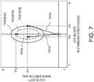
- Fig. 7 is a view illustrating one example of the wind force characteristic chart generated by the image generating module 15.
- the wind force characteristic chart illustrated in Fig. 7 for example, since the log velocity vector of the first ship in a case where wind of V WD1 [m/s] acts on the first ship from a right direction thereof is V WTA , it is understood that the log velocity of the first ship in the starboard direction is V X1 [m/s] and the log velocity of the first ship in the bow direction is V Y1 [m/s].
- the log velocity vector of the first ship in a case where wind of V WD2 [m/s] acts on the first ship from a rear direction thereof is V WTB , it is understood that the log velocity of the first ship in the starboard direction is 0 [m/s] and the log velocity of the first ship in the bow direction is V Y2 [m/s].
- the log velocity vector of the first ship in a case where wind of V WD3 [m/s] acts on the first ship from a left direction thereof is V WTC , it is understood that the log velocity of the first ship in the starboard direction is V X1 [m/s] and the log velocity of the first ship in the bow direction is V Y1 [m/s].
- the wind force characteristic estimating device 9 it is possible to easily grasp the relationship between the wind velocity vector which is one of the parameters which influence the log velocity of the first ship, and the log velocity of the first ship caused by the wind velocity vector.
- the estimator 12 is configured by using the neural network. Thus, it is possible to suitably configure the estimator 12 capable of outputting the log velocity.
- the estimator 12 is updated to reduce the error of each second output value of the estimator 12 with respect to the ground velocity calculated by the ground velocity calculating module 11.
- the estimator 12 is configured with the learning function.
- the wind force characteristic estimating device 9 is capable of accumulating a large amount of data required for estimating an accurate log velocity during the travel, it is possible to omit works of preparing these multiple learning data (data of a ground velocity under a certain condition) in advance and setting a suitable coupling coefficient based on these learning data.
- the estimating apparatus 1h includes a surface current estimating device 8 and a propulsion system characteristic estimating device 9h (ship characteristic estimating device). Since the configuration and operation of the surface current estimating device 8 are the same as the surface current estimating device 8 of the estimating apparatus 1 according to the embodiment described above, the description thereof is omitted.
- the propulsion system characteristic estimating device 9h includes a GPS signal receiver 2, a propeller speed detector 3, a vane anemometer 4, a data output unit 6a, one or some of components constituting the calculator 10h (e.g., a ground velocity calculating module 11, an estimator 12h, a coupling coefficient updating module 14, and an image generating module 15a), and a display unit 5. Since the configurations and operations of the GPS signal receiver 2, the propeller rotational speed detector 3, and the vane anemometer 4 are similar to the case of the surface current estimating device 8, the description thereof is omitted.
- the wind velocity vector data V WD1 of the parameter data Dn indicate the same wind velocity vector, whereas the rotational speed data R n of the parameter data Dn indicate different rotational speeds.
- the data output unit 6 outputs a true wind speed in a bow direction and a true wind speed in a starboard direction, as the wind velocity vector data V WD1 .
- the instruction signal S described above is, for example, outputted to the data output unit 6a upon a suitable operation by a user on a control panel (not illustrated) provided to the estimating apparatus 1h.
- the user may input a value of a desirable wind velocity vector (e.g., 0 [m/s]) through the control panel.
- the calculator 10h is configured to estimate the propulsion system characteristics based on the parameter data Dn outputted from the data output unit 6 as described above. Note that since the configurations and operations of the ground velocity calculating module 11 and the coupling coefficient updating module 14 of calculator 10h are similar to the case of the surface current estimating device 8 described above, the description thereof is omitted.
- the estimator 12h is configured to estimate the log velocity of the first ship.
- the estimator 12h receives the parameter data Dn outputted from the data output unit 6a, estimates the values corresponding thereto to be the magnitude
- of the log velocity V WTn (n 1, 2, 7), and outputs it as the first output value to the image generating module 15.
- the estimator 12h receives the plurality of parameter data Dn as described above. Further the wind velocity vector data V WD1 of the parameter data Dn indicate the same wind velocity vector, and the rotational speed R n of the parameter data Dn indicate different propeller rotational speeds. Thus, the estimator 12h outputs the magnitude
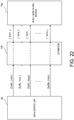
- FIG. 22 is a view illustrating a correspondence of the plurality of parameter data Dn outputted from the data output unit 6a, with the magnitudes
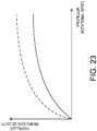
- Fig. 23 is a view illustrating one example of a propulsion system characteristic chart generated by the image generating module 15a.
- the image generating module 15a generates the propulsion system characteristic chart indicated by the solid line of Fig. 23 .
- the image generating module 15a plots on coordinates illustrated in Fig. 23 (the vertical axis indicates the magnitude of the log velocity and the horizontal axis indicates the rotational speed of the propeller) points defined by the propeller propulsion velocity
- the image generating module 15a calculates, by using regression analysis etc., a curve (propulsion system characteristics) indicated by the solid line of Fig. 23 , based on the plurality of plotted points. Moreover, this propulsion system characteristic chart is displayed on the display unit 5.
- the propulsion system characteristics are ideal characteristics in trial for a new ship or immediately after repairing, for example, characteristics with which the propeller propulsion velocity with respect to the propeller rotational speed becomes higher (see the dashed line of Fig. 23 ). Therefore, for example, by comparing the propulsion system characteristics in trial for a new ship with the propulsion system characteristics of the first ship at a current time point, it is possible to estimate a deteriorated state of an engine, a stain state of a ship body surface, etc. By knowing these states, it is possible for the user to determine a more accurate operation plan, necessity of abnormality checkup, etc.
- the propulsion system characteristic estimating device 9h it is possible to easily grasp the relationship between the propeller rotational speed which is one of the parameters which influence the log velocity of the first ship, and the log velocity of the first ship caused by the rotational speed.
- the estimator 12h is configured by using the neural network.
- the estimator 12 capable of outputting the log velocity.
- the estimator 12h is updated to reduce the error of each second output value of the estimator 12h with respect to the ground velocity calculated by the ground velocity calculating module 11.
- the propulsion system characteristic estimating device 9h is capable of accumulating a large amount of data required for estimating an accurate log velocity during the travel, it is possible to omit works of preparing these multiple learning data (data of a ground velocity under a certain condition) in advance and setting a suitable coupling coefficient based on these learning data.
- Fig. 29 is a schematic view illustrating complement of the learning data. Since a ship has a substantially laterally symmetrical shape, the wind force characteristics are estimated to be laterally symmetric as well. Specifically, for example, between a case where a ship traveling under a certain condition receives wind from the port quarter at an angle of 45 degrees and a case where the ship receives wind from the starboard quarter at an angle of 45 degrees (wind velocities are the same), the traveling directions are estimated to be laterally symmetric. Therefore, with reference to Fig.
- the data may be complemented as follows based on learning data thereof.
- learning data for when the propeller rotational speed and the wind speed are the same as the learning data of the above case and the wind direction is on the starboard quarter at an angle of 45 degrees a laterally inverted vector V' G may be complemented.
Landscapes
- Engineering & Computer Science (AREA)
- Chemical & Material Sciences (AREA)
- Combustion & Propulsion (AREA)
- Mechanical Engineering (AREA)
- Ocean & Marine Engineering (AREA)
- Physics & Mathematics (AREA)
- General Physics & Mathematics (AREA)
- Aviation & Aerospace Engineering (AREA)
- Radar, Positioning & Navigation (AREA)
- Remote Sensing (AREA)
- Life Sciences & Earth Sciences (AREA)
- Atmospheric Sciences (AREA)
- Environmental & Geological Engineering (AREA)
- Automation & Control Theory (AREA)
- Indicating Or Recording The Presence, Absence, Or Direction Of Movement (AREA)
- Radar Systems Or Details Thereof (AREA)
- Navigation (AREA)
- Control Of Position, Course, Altitude, Or Attitude Of Moving Bodies (AREA)
Abstract
Description
- This disclosure relates to a ship characteristic estimating device which estimates characteristics of a ship, and an autopilot system which includes the ship characteristic estimating device.
- Conventionally, various kinds of schemes are tried out to accurately grasp a state of a ship (characteristics of a ship which change over time). For example,
Patent Document 1 discloses a system capable of diagnosing a state of a ship based on operational information (temperature, pressure, rotational speed etc. of a propulsion system of the ship) detected by various sensors attached to the ship. - Patent Document 1:
JP2002-316692A - Incidentally, in grasping a state of a ship, it is extremely important to grasp a relationship of parameter values which influence a log velocity of the ship (a velocity of the ship over water), with an actual log velocity of the ship corresponding to the respective values. By grasping this relationship, for example, it becomes possible to plan a travel of the ship more accurately. However, nothing regarding this is described in the patent document described above.
- For example, examples of the parameters which influence the log velocity of the ship include a rotational speed of a propeller of the ship and wind force against the ship. Moreover, in a certain ship, to grasp a relationship between the rotational speed of the propeller and the log velocity of the ship caused by the rotational speed, experiments need to be conducted while the other parameters which influence the log velocity of the ship (wind force etc.) are kept stable, which is extremely troublesome. This is similar in a case of grasping a relationship between the wind force against the ship and the log velocity of the ship caused by the wind force.
- This disclosure is to solve the above situations and aims to easily grasp a relationship of parameter values which influence a log velocity of a ship, with the log velocity of the ship caused by the parameters.
-
- (1) To solve the above problems, according to one aspect of the present disclosure, a ship characteristic estimating device is provided. The device includes a data output unit configured to output a plurality of parameter data respectively including rotational speed data indicating a rotational speed of a propeller of a ship, and wind velocity vector data indicating a wind velocity vector of wind force that may act on the ship, and an estimator configured to receive the plurality of parameter data outputted from the data output unit, estimate values corresponding to the respective parameter data to be log velocity vectors of the ship, and output the log velocity vectors as first output values. The rotational speed data included in the plurality of parameter data indicate the same rotational speed, and the wind velocity vector data included in the plurality of parameter data indicate different wind velocity vectors. Each of the first output values is estimated and outputted as the log velocity vector of the ship when the ship travels at the rotational speed indicated by the rotational speed data.
- (2) To solve the above problems, according to another aspect of the present disclosure, a ship characteristic estimating device is provided. The device includes a data output unit configured to output a plurality of parameter data respectively including rotational speed data indicating a rotational speed of a propeller of a ship, and wind velocity vector data indicating a wind velocity vector of wind force that may act on the ship, and an estimator configured to receive the plurality of parameter data outputted from the data output unit, estimate values corresponding to the respective parameter data to be log velocity vectors of the ship, and output the log velocity vectors as first output values. The rotational speed data included in the plurality of parameter data indicate different rotational speeds, and the wind velocity vector data included in the plurality of parameter data indicate the same wind velocity vector. Each of the first output values is estimated and outputted as the log velocity vector of the ship when the wind velocity vector indicated by the wind velocity vector data acts on the ship.
- (3) The estimator may be configured using a neural network. The estimator may have at least two input units, respectively configured to receive one of the rotational speed data and the wind velocity vector data, and an output unit configured to output the first output value. Values outputted from the input units of the neural network may be multiplied by a coupling coefficient and then transmitted to the output unit.
- (4) The ship characteristic estimating device may further include a ground velocity calculating module configured to calculate a ground velocity vector of the ship traveling on water, a propeller speed detector configured to detect the rotational speed of the propeller, and a vane anemometer equipped in the ship and configured to measure the wind velocity vector of the wind force against the ship. Each of the input units may receive one of the rotational speed of the propeller detected by the propeller speed detector, and the wind velocity vector measured by the vane anemometer. The output unit may estimate, as the log velocity vector of the ship, a value corresponding to a condition defined by a combination of the rotational speed of the propeller detected by the propeller speed detector and the wind velocity vector measured by the vane anemometer, and output the value as a second output value. The device may further include an updating module configured to compare the second output value with the ground velocity vector calculated as a teaching signal by the ground velocity calculating module, and update the coupling coefficient to reduce an error between the second output value and the teaching signal.
- (5) The estimator may have a memory including a plurality of cells respectively configured to store the ground velocity vector of the ship under one of a plurality of conditions defined by a combination of the rotational speed of the propeller of the ship and the wind velocity vector of the wind force against the ship for every one of the plurality of conditions, and the estimator may output, as the first output value, an average value of the ground velocity vectors stored in the cells specified by the condition corresponding to the combination of the rotational speed data and the wind velocity vector data included in the received parameter data.
- (6) The ship characteristic estimating device may further include a ground velocity calculating module configured to calculate a ground velocity vector of the ship traveling on water, a propeller speed detector configured to detect the rotational speed of the propeller, and a vane anemometer equipped in the ship and configured to measure the wind velocity vector of the wind force against the ship. The memory may further include an updating module configured to store the ground velocity vector calculated by the ground velocity calculating module in the cell specified by a combination of the rotational speed detected by the propeller speed detector and the wind velocity vector measured by the vane anemometer when data required for calculating the ground velocity vector is acquired.
- (7) The ship characteristic estimating device may further include a display unit configured to display a range where the ship is predicted to be located therein after a particular period of time from a current time point, based on the first output value outputted from the estimator.
- (8) To solve the above problems, according to another aspect of the present disclosure, an autopilot system is provided. The system includes a GNSS signal receiver equipped in a ship and configured to receive GNSS signals, and a controller configured to control a rudder angle of the ship based on positional information of the ship that is calculated based on GNSS signals received by the GNSS signal receiver, and further includes any one of the ship characteristic estimating device described above. The controller controls the rudder angle of the ship based also on the first output value outputted from the estimator of the ship characteristic estimating device.
- According to this disclosure, it is possible to easily grasp a relationship of parameter values which influence a log velocity of a ship, with the log velocity of the ship caused by the parameters.
-
-
Fig. 1 is a block diagram illustrating a configuration of an estimating apparatus according to one embodiment of this disclosure. -
Fig. 2 is a schematic view illustrating one example of a configuration of an estimator illustrated inFig. 1 . -
Fig. 3 is a vector diagram illustrating a relationship of a ground velocity, a log velocity, and a surface current velocity. -
Fig. 4 is a view illustrating how a second output value from the estimator illustrated inFig. 1 converges to the log velocity. -
Fig. 5 is a view illustrating a correspondence of a plurality of parameter data outputted from a data output unit illustrated inFig. 1 , with log velocities estimated based on the parameter data by the estimator, respectively. -
Fig. 6 is a view illustrating a generation process of a wind force characteristic chart generated by an image generating module illustrated inFig. 1 . -
Fig. 7 is a view illustrating one example of the wind force characteristic chart generated by the image generating module. -
Fig. 8 is a block diagram illustrating a configuration of an estimating apparatus according to a modification. -
Fig. 9 is a block diagram illustrating a configuration of an estimating apparatus according to a modification. -
Fig. 10 is a block diagram illustrating a configuration of an estimating apparatus according to a modification. -
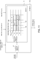
Fig. 11 is a view illustrating in detail an estimator illustrated inFig. 10 . -
Fig. 12 is a block diagram illustrating a configuration of an estimating apparatus according to a modification. -
Fig. 13 is a block diagram illustrating a configuration of an estimating apparatus according to a modification. -
Fig. 14 is a block diagram illustrating a configuration of a learning coefficient setting processor illustrated inFig. 13 . -
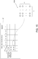
Fig. 15 is a view schematically illustrating a table stored in a memory illustrated inFig. 14 , and a self-organizing map stored in association with a plurality of cells of the table. -
Fig. 16 is a block diagram illustrating a configuration of a learning coefficient setting processor of an estimating apparatus according to a modification. -
Fig. 17 is a view illustrating a table stored in a memory illustrated inFig. 16 , and learning data stored in association with each cell (each area) of the table. -
Fig. 18 is a block diagram illustrating a configuration of an estimating apparatus according to a modification. -
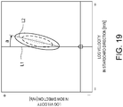
Fig. 19 is a view illustrating one example of a wind force characteristic chart generated by an image generating module illustrated inFig. 18 , illustrating a deriving process of a learning progress index. -
Fig. 20 is a block diagram illustrating a configuration of an autopilot system. -
Fig. 21 is a block diagram illustrating a configuration of an estimating apparatus according to a modification. -
Fig. 22 is a view illustrating a correspondence of each parameter data outputted from a data output unit illustrated inFig. 21 , with a log velocity estimated based on the parameter data by the estimator, respectively. -
Fig. 23 is a view illustrating one example of a propulsion system characteristic chart generated by an image generating module. -
Fig. 24 is a block diagram illustrating a configuration of an estimating apparatus according to a modification. -
Fig. 25 is a view illustrating one example of a rotational speed meter displayed on a display unit. -
Fig. 26 is a block diagram illustrating a configuration of an estimating apparatus according to a modification. -
Fig. 27 is a view illustrating one example of a propulsion system characteristic chart generated by an image generating module, illustrating a learning progress index. -
Fig. 28 is one example of a map displayed on a display unit of an estimating apparatus according to a modification, indicating a position of a first ship after a particular period of time from a current time point. -
Fig. 29 is a schematic view illustrating complement of learning data. -
Fig. 1 is a block diagram illustrating a configuration of anestimating apparatus 1 according to one embodiment of this disclosure. The estimatingapparatus 1 is equipped in a first ship (ship) which travels on water. - As illustrated in
Fig. 1 , the estimatingapparatus 1 includes a surfacecurrent estimating device 8 and a wind force characteristic estimating device 9 (ship characteristic estimating device). The surfacecurrent estimating device 8 is configured to estimate a direction and magnitude of a surface current at a position of the first ship, in other words, a velocity vector of the surface current at the first ship position. On the other hand, the wind forcecharacteristic estimating device 9 is configured to estimate wind force characteristics of the first ship. Hereinafter, a configuration of the surfacecurrent estimating device 8 and a configuration of the wind forcecharacteristic estimating device 9 are described in this order. Note that the surface current is a flow within a depth range which is about a range from a water surface to a bottom of the first ship. Further the wind force characteristics are characteristics indicating how a moving speed of the first ship changes on static water due to a bearing and magnitude of the wind force against the first ship. - The surface
current estimating device 8 automatically obtains particular parameters (in this embodiment, a rotational speed of a propeller of the first ship, a true wind speed in a bow direction, and a true wind speed in a starboard direction) at every particular timing, and calculates a surface current velocity (surface current velocity vector) at the first ship position for every condition defined by a combination of values of the respective parameters. The surfacecurrent estimating device 8 includes aGPS signal receiver 2, apropeller speed detector 3, avane anemometer 4, one or some of components constituting a calculator 10 (e.g., a groundvelocity calculating module 11, anestimator 12, a surface current calculatingmodule 13, and a coupling coefficient updating module 14), and adisplay unit 5. - The
GPS signal receiver 2 is provided as a GNSS signal receiver configured to receive GPS signals as navigation signals (GNSS signals) which are transmitted from navigation satellites (not illustrated). TheGPS signal receiver 2 includes a GPS antenna, for example. The GPS signals received by the GPS signal receiver 2 (i.e., positional information of the first ship) are notified to thecalculator 10 along with a received time point of the GPS signals. - Note that in this embodiment, the
GPS signal receiver 2 is used as the GNSS signal receiver; however, without limiting to this, a receiver used in another GNSS system may be used. Here, GNSS is an abbreviation of Global Navigation Satellite Systems. This GNSS is a collective name for "GPS" administrated by the United States of America, "GALILEO" administrated by the European Union, "GLONASS" administrated by Russia, etc. - The
propeller speed detector 3 detects a rotational speed per unit time of the propeller configured to produce a propulsion force (thrust) of the first ship, and includes a sensor capable of detecting a rotational speed, for example. The rotational speed detected by thepropeller speed detector 3 is notified to thecalculator 10. - The
vane anemometer 4 measures, as information of a wind direction and speed, the true wind speed in the bow direction and the true wind speed in the starboard direction. Thevane anemometer 4 is disposed in the first ship where the surfacecurrent estimating device 8 according to this embodiment is equipped, at a location with no obstacle in its surrounding which blocks wind. The true wind speed in the bow direction and the true wind speed in the starboard direction measured by thevane anemometer 4 are notified to thecalculator 10. - The
calculator 10 is configured to estimate a surface current at the first ship position (target location) at every particular timing, based on the various information notified by theGPS signal receiver 2, thepropeller speed detector 3, and thevane anemometer 4. Thecalculator 10 includes the groundvelocity calculating module 11, theestimator 12, the surface current calculatingmodule 13, and the couplingcoefficient updating module 14. Note that, although it is described later in detail, thecalculator 10 is configured to also estimate the wind force characteristics based on the parameters outputted from adata output unit 6. - The ground
velocity calculating module 11 calculates a ground velocity (ground velocity vector) of the first ship based on the positional information of the first ship and the acquired time point of the first ship positional information, which are notified from theGPS signal receiver 2. Specifically, the groundvelocity calculating module 11 calculates the ground velocity of the first ship based on first ship positions of at least two timings and acquired time points of the positional information of the respective first ship positions. The groundvelocity calculating module 11 notifies the ground velocity calculated as above, to the surface current calculatingmodule 13 and the couplingcoefficient updating module 14. - The
estimator 12 is configured to estimate a log velocity of the first ship. In this embodiment, theestimator 12 receives the rotational speed of the propeller of the first ship, which is detected by thepropeller speed detector 3, and the true wind speed in the bow direction and the true wind speed in the starboard direction, which are measured by the vane anemometer. Theestimator 12 outputs to the surface current calculating module 13 a value corresponding to a condition defined by a combination of these input values (a condition defined by a combination of a certain rotational speed, a certain true wind speed in the bow direction, and a certain true wind speed in the starboard direction) as the log velocity (log velocity vector, which is a log velocity in the bow direction and a log velocity in the starboard direction in this embodiment). Note that, although it is described later in detail, theestimator 12 also receives the parameter data outputted from thedata output unit 6, and theestimator 12 outputs a value corresponding thereto to animage generating module 15 as the log velocity. -
Fig. 2 is a schematic view illustrating one example of a configuration of theestimator 12. In this embodiment, theestimator 12 is configured using a commonly-known neural network. For example, theestimator 12 includes a plurality of input units UIN_1, UIN_2 and UIN_3 structuring an input layer, a plurality of middle units UMID_1, UMID_2 and UMID_3 structuring a hidden layer, and a plurality of output units UOUT_1 and UOUT_2 structuring an output layer. Note that, the configuration of theestimator 12 illustrated inFig. 2 is merely an example, and the number of units in each layer, the number of hidden layers are not limited to those illustrated inFig. 2 . - In the
estimator 12, when the input values (the rotational speed of the propeller, etc.) are inputted into the respective input units UIN_1, UIN_2 and UIN_3, each of those input values is multiplied by a coupling coefficient WI,M and outputted to the middle units UMID_1, UMID 2 and UMID_3 of the hidden layer. Each of the middle units UMID_1, UMID 2 and UMID_3 of the hidden layer adds up the inputted values to obtain a total, multiplies by a coupling coefficient WM,O a value obtained based on the total value, and outputs it to the output units UOUT_1 and UOUT_2. Each of the output units UOUT_1 and UOUT_2 adds up the inputted values to obtain a total, and outputs, as a second output value, a value obtained based on the total value, to the surface current calculatingmodule 13 and the couplingcoefficient updating module 14. Note that, the values inputted into theestimator 12 are not necessarily the values of the parameter themselves, such as the rotational speed of the propeller, etc., and they may be numerical values which are in a one-to-one relationship with those parameters, respectively (e.g., a voltage value which changes in proportion to the rotational speed), etc. - In an initial state of the
estimator 12, a suitable initial value is set for each coupling coefficient W. Further, the coupling coefficient W is updated by the couplingcoefficient updating module 14 as needed. For example, the coupling coefficient W is updated by the couplingcoefficient updating module 14 to reduce an error of each second output value outputted from theestimator 12 with respect to the ground velocity (teaching signal) calculated by the groundvelocity calculating module 11. Thus, the second output value outputted from theestimator 12, although described later in detail, is converged to the log velocity of the first ship every time the coupling coefficient W is updated. - The surface current calculating
module 13 calculates a surface current velocity (surface current velocity vector) that is a velocity of a surface current, based on the second output values as the log velocity outputted from theestimator 12 and the ground velocity calculated by the groundvelocity calculating module 11. For example, the surface current calculatingmodule 13 calculates the surface current velocity by subtracting the log velocity from the ground velocity. -
Fig. 3 is a vector diagram illustrating a relationship among the ground velocity vector VG, the log velocity vector VW, and the surface current velocity vector VT. The ground velocity VG is a velocity over a ground surface, and the log velocity VW is a velocity over a water surface (sea surface). Further, the surface current is a water current in a surface zone of the sea. Therefore, the relationship among the ground velocity vector VG, the log velocity vector VW, and the surface current velocity vector VT may be expressed as illustrated inFig. 3 . Thus, the surface current calculatingmodule 13 subtracts the log velocity VW from the ground velocity VG as described above to calculate the surface current velocity VT. - The coupling
coefficient updating module 14 updates each coupling coefficient W of theestimator 12 to reduce the error of each second output value from theestimator 12 with respect to the ground velocity (teaching signal) calculated by the groundvelocity calculating module 11. The couplingcoefficient updating module 14 updates the coupling coefficient W by using a backpropagation method, for example. - The
display unit 5 displays the direction and magnitude of the surface current calculated by the surface current calculatingmodule 13, which enables a user to learn the velocity of the surface current at the first ship position. -
Fig. 4 is a view illustrating how each second output value from theestimator 12 converges to the log velocity every time the coupling coefficient W of theestimator 12 is updated. As described above, each coupling coefficient W stored in theestimator 12 is updated by the couplingcoefficient updating module 14 to reduce the error of the output value, which is outputted from theestimator 12 as needed, with respect to the ground velocity as the teaching signal calculated as needed. - The surface current varies in magnitude and direction depending on a marine area, time, a meteorological condition, etc. Thus, when the log velocity is the same (i.e., when the rotational speed of the propeller, the true wind speed in the bow direction, and the true wind speed in the starboard direction are the same), the ground velocity is considered to contain components of surface current velocities of various magnitudes and directions. Therefore, by averaging these components (averaging VG1 to VG6 in the case of
Fig. 4 ), the surface current velocity components cancel out each other and the log velocity component remains. In other words, as the coupling coefficient W of theestimator 12 is updated to reduce the error of the second output value of theestimator 12 with respect to the ground velocity as described above, an influence of the surface current velocity components contained in the ground velocity gradually becomes smaller; therefore, the second output value of theestimator 12 converges to the log velocity. Thus, in a stage where the learning data (ground velocity data) is sufficiently obtained and the learning process has sufficiently progressed (i.e., in a stage where the coupling coefficient has been updated a sufficient number of times), the second output value from theestimator 12 can be estimated as the log velocity. - With the surface
current estimating device 8, at every particular timing during travel of the first ship, the rotational speed is detected by thepropeller speed detector 3, and the true wind speed in the bow direction and the true wind speed in the starboard direction are measured by thevane anemometer 4, and these information are outputted to theestimator 12 as needed. Theestimator 12 generates the second output value based on these information by using the coupling coefficient W updated as needed during travel of the first ship. - The wind force
characteristic estimating device 9 includes theGPS signal receiver 2, thepropeller speed detector 3, thevane anemometer 4, thedata output unit 6, one or some of the components constituting the calculator 10 (e.g., the groundvelocity calculating module 11, theestimator 12, the couplingcoefficient updating module 14, and the image generating module 15), and thedisplay unit 5. Since the configurations and operations of theGPS signal receiver 2, thepropeller speed detector 3, and thevane anemometer 4 are similar to the case of the surfacecurrent estimating device 8 described above, the description thereof is omitted. - Once the
data output unit 6 receives an instruction signal which is a signal to cause derivation of the wind force characteristics of the first ship, it sequentially outputs a plurality of parameter data Dn (n= 1, 2, ...) to theestimator 12. Each parameter data Dn includes rotational speed data R1 indicating the rotational speed of the propeller and wind velocity vector data VWDn (n= 1, 2, ...) indicating a wind velocity vector. The rotational speed data R1 of the parameter data Dn indicate the same rotational speed, whereas the wind velocity vector data VWDn of the parameter data Dn indicate different wind velocity vectors. In this embodiment, thedata output unit 6 outputs the true wind speed in the bow direction and the true wind speed in the starboard direction, as the wind velocity vector data VWDn. - Note that, the instruction signal S described above is, for example, outputted to the
data output unit 6 upon a suitable operation by a user on a control panel (not illustrated) provided to theestimating apparatus 1. Here, the user may input a value of a desirable rotational speed R1 through the control panel, for example. - The
calculator 10 is configured to estimate the wind force characteristics based on the parameter data Dn outputted from thedata output unit 6 as described above. Note that since the configurations and operations of the groundvelocity calculating module 11 and the couplingcoefficient updating module 14 ofcalculator 10 are similar to the case of the surfacecurrent estimating device 8 described above, the description thereof is omitted. - As described above, the
estimator 12 is configured to estimate the log velocity of the first ship. Theestimator 12 receives the parameter data Dn outputted from thedata output unit 6, estimates values corresponding thereto to be log velocities VWTn (n= 1, 2, ...) (in this embodiment, the true wind speed in the bow direction and the true wind speed in the starboard direction), and outputs to theimage generating module 15 the log velocities VWTn as first output values. - Moreover the
estimator 12 receives the plurality of parameter data Dn as described above. Further the rotational speed data R1 of the parameter data Dn indicate the same rotational speed, and the wind velocity vector data VWDn of the parameter data Dn indicate different wind velocity vectors. Thus, the log velocities VWTn in a case where the rotational speed of the propeller is fixed and different forces of wind act on the first ship from different bearings are outputted as the first output values by theestimator 12.Fig. 5 is a view illustrating a correspondence of the plurality of parameter data Dn outputted from thedata output unit 6, with the log velocities VWTn (first output values) estimated based on the parameter data Dn by theestimator 12, respectively. -
Fig. 6 is a view illustrating a generation process of a wind force characteristic chart generated by theimage generating module 15. For example, theimage generating module 15 generates a closed curve by connecting terminal points of two or more log velocities VWTn which are estimated with the wind velocity vector VWDn of the same magnitude, among a plurality of log velocities VWTn (n= 1, 2, ...) originated at the same position (seeFig. 6 ). Note that,Fig. 6 only illustrates the plurality of log velocities VWTn of which magnitudes of the wind velocity vectors VWDn are same so as to avoid the drawing from becoming complex. -
Fig. 7 is a view illustrating one example of the wind force characteristic chart generated by theimage generating module 15. According to the wind force characteristic chart illustrated inFig. 7 , for example, since the log velocity vector of the first ship in a case where wind of VWD1 [m/s] acts on the first ship from a right direction thereof is VWTA, it is understood that the log velocity of the first ship in the starboard direction is VX1 [m/s] and the log velocity of the first ship in the bow direction is VY1 [m/s]. Further, since the log velocity vector of the first ship in a case where wind of VWD2 [m/s] acts on the first ship from a rear direction thereof is VWTB, it is understood that the log velocity of the first ship in the starboard direction is 0 [m/s] and the log velocity of the first ship in the bow direction is VY2 [m/s]. Moreover, since the log velocity vector of the first ship in a case where wind of VWD3 [m/s] acts on the first ship from a left direction thereof is VWTC, it is understood that the log velocity of the first ship in the starboard direction is VX1 [m/s] and the log velocity of the first ship in the bow direction is VY1 [m/s]. - In other words, according to this wind force characteristic chart, it is easily understood visually a substantial magnitude of the log velocity of the first ship due to the influence of wind when the rotational speed of the propeller of the first ship is fixed.
- As described above, with the wind force
characteristic estimating device 9 of theestimating apparatus 1 according to this embodiment, when the first ship travels with a certain fixed rotational speed, it is possible to estimate a change of the log velocity of the first ship due to the wind force which may act on the first ship. - Therefore, according to the wind force
characteristic estimating device 9, it is possible to easily grasp the relationship between the wind velocity vector which is one of the parameters which influence the log velocity of the first ship, and the log velocity of the first ship caused by the wind velocity vector. - Further, with the wind force
characteristic estimating device 9, theestimator 12 is configured by using the neural network. Thus, it is possible to suitably configure theestimator 12 capable of outputting the log velocity. - Further, with the wind force
characteristic estimating device 9, theestimator 12 is updated to reduce the error of each second output value of theestimator 12 with respect to the ground velocity calculated by the groundvelocity calculating module 11. Thus, it is possible to configure theestimator 12 with the learning function. Additionally, since the wind forcecharacteristic estimating device 9 is capable of accumulating a large amount of data required for estimating an accurate log velocity during the travel, it is possible to omit works of preparing these multiple learning data (data of a ground velocity under a certain condition) in advance and setting a suitable coupling coefficient based on these learning data. - Although the embodiment of this disclosure is described, this disclosure is not limited to this, and various changes may be applied without deviating from the scope of this disclosure.
-
- (1)
Fig. 8 is a block diagram illustrating a configuration of anestimating apparatus 1a according to a modification. Acalculator 10a of theestimating apparatus 1a according to this modification is different from thecalculator 10 of the embodiment described above, and has a configuration in which the surface current calculatingmodule 13 is omitted. That is, the estimatingapparatus 1a according to this modification does not have a function as the surfacecurrent estimating device 8, and is provided as a wind forcecharacteristic estimating device 9. Therefore, in accordance with the estimatingapparatus 1a according to this modification, different from the case of the embodiment described above, the surface current near the first ship cannot be estimated, whereas similarly to the case of the embodiment described above, the wind force characteristics of the first ship can be estimated. - (2)
Fig. 9 is a block diagram illustrating a configuration of anestimating apparatus 1b according to a modification. The estimatingapparatus 1b according to this modification is different from the estimatingapparatus 1a illustrated inFig. 8 , and has a configuration in which the couplingcoefficient updating module 14 is omitted. That is, the estimatingapparatus 1b according to this modification does not have a learning function. Further, in the configuration of theestimating apparatus 1b according to this modification, theGPS signal receiver 2, the groundvelocity calculating module 11, thepropeller speed detector 3, and thevane anemometer 4 are also omitted.
The estimatingapparatus 1b according to this modification generates the wind force characteristic chart based on the log velocity outputted from the estimator 12a of which a coupling coefficient W is determined based on many learning data acquired in advance (data of a ground velocity under a certain condition). Also with such a configuration, similar to the case of theestimating apparatus 1a illustrated inFig. 8 , it is possible to easily estimate the change of the log velocity of the first ship due to the wind force which may act on the first ship when the first ship travels with a certain fixed rotational speed. - (3)
Fig. 10 is a block diagram illustrating a configuration of an estimating apparatus 1c according to a modification. Compared to theestimating apparatus 1 illustrated inFig. 8 , the estimating apparatus 1c according to this modification has a significantly different configuration for anestimator 12c. Specifically, theestimator 12c is not configured using a neural network, and has a configuration including amemory 16 and an updatingmodule 17.
Fig. 11 is a view illustrating in detail theestimator 12c illustrated inFig. 10 .
Thememory 16 stores a matrix table as illustrated inFig. 11 . This table stores ground velocities calculated under respective conditions (corresponding torespective cells 16a of the table). Each condition is defined by a combination of a value of a wind direction and speed (X1, X2, X3, ...) and a value of the rotational speed (R1, R2, R3, ...). InFig. 11 , a single value of ground velocity is indicated with a single circular mark. That is, thememory 16 stores, for example, five values of ground velocity calculated when the value of the wind direction and speed is X1 and the value of the rotational speed is R1.
Once theestimator 12c receives the rotational speed detected by the propeller speed detector 3 (e.g., R2) and the wind direction and speed measured by the vane anemometer 4 (e.g., X3), theestimator 12c calculates an average value of the ground velocities contained in thecell 16a where the rotational speed is R2 and the wind direction and speed is X3 (eleven values in the case ofFig. 11 ). Further, theestimator 12c outputs the average value as an output value.
As described above usingFig. 4 , by averaging the ground velocities under a certain condition (a condition defined by a combination of a certain rotational speed and a certain wind direction and speed), surface current velocity components contained in the ground velocities cancel out each other, and thus, the average value becomes a value close to a log velocity. Therefore, also by theestimator 12c according to this modification, it is possible to appropriately estimate the log velocity.
The updatingmodule 17 updates the table stored in thememory 16, by using a ground velocity calculated at a timing at which a rotational speed and a wind direction and speed inputted into theestimator 12c are detected. For example, the ground velocity calculated at a particular rotational speed (e.g., R3) and a particular wind direction and speed (e.g., X2) is added to acell 16a defined by R3 and X2. By performing this operation as needed, learning data is accumulated even while traveling, and a log velocity can be estimated more accurately. In other words, theestimator 12c according to this modification also has a learning function. As a result, it is possible to derive the wind force characteristics more accurately.
Note that, by configuring this modification to omit the updatingmodule 17, anestimating apparatus 1d which does not have the learning function (seeFig. 12 ) can be configured. In this case, a plurality of leaning data acquired in advance (each data corresponds to a single circular mark inFig. 11 ) needs to be stored in thememory 16. - (4)
Fig. 13 is a block diagram illustrating a configuration of anestimating apparatus 1e according to a modification. Theestimating apparatus 1e according to this modification has a configuration of theestimating apparatus 1a illustrated inFig. 8 , further provided with a learningcoefficient setting processor 20.
Anestimator 12, similar to the case of the above embodiment, is configured using a neural network and such that a coupling coefficient is updated as needed by so-called supervised learning. With theestimating apparatus 1e, an error between an output value from the estimator 12e and a teaching signal (ground velocity) is calculated. Then, theestimating apparatus 1e updates the coupling coefficient W while propagating the error as a learning signal, from a unit on an output layer side to a unit on an input layer side. A correction amount of the coupling coefficient is given by the followingEquation 1.
InEquation 1, ΔWi,j n,n-1(t) is a correction amount on a weight of coupling between a unit j of an (n-1)th layer and a unit i of an n-th layer, η is a learning coefficient, δi n is a learning signal to be returned back to each unit of the (n-1)th layer from the unit i of the n-th layer, Xj n-1 is an output value of the unit j of the (n-1)th layer, α is a stabilizing coefficient, and ΔWi,j n,n-1(t-1) is a previous correction amount. Note that, the (n-1)th layer is one layer on the input side of the n-th layer.
Fig. 14 is a block diagram illustrating a configuration of the learningcoefficient setting processor 20. The learningcoefficient setting processor 20 sets the learning coefficient inEquation 1 as needed. As illustrated inFig. 14 , the learningcoefficient setting processor 20 has amemory 21, anSOM updating module 22, acounting module 23, a learningcoefficient calculating module 24, and a learningcoefficient setting module 25.
Fig. 15 is a view schematically illustrating a table stored in thememory 21, and a self-organizing map SOM stored in association with each cell of the table. As illustrated inFig. 15 , thememory 21 stores a table sectioned for every particular propeller rotational speed and every particular wind speed and direction in a grid pattern. Each cell of this table stores a corresponding self-organizing map SOM. Each self-organizing map SOM of this modification is a two-dimensional SOM formed with an n×n number of units. Each unit stores a reference vector of the same dimension as that of an input vector. In an initial state (a state where the learning is not performed), a suitable reference vector is set into the unit.
TheSOM updating module 22 updates the SOM according to the input vector (a vector formed based on a rotational speed of the propeller, a wind direction and speed, a ground velocity, etc. which are inputted at every particular timing). Specifically, theSOM updating module 22 updates as below, the SOM stored in the cell including the inputted rotational speed and the inputted wind direction and speed.
For example, by using a unit with a shortest Euclidean distance from the input vector as a winner unit, theSOM updating module 22 updates a reference vector stored in the winner unit and reference vectors stored in units around the winner unit, based on the followingEquation 2.
Note that, mi is the reference vector, x(t) is the input vector, and hi is a neighborhood function expressed by c×exp(-dis2/α2). In the neighborhood function, c is a learning rate coefficient, and dis=|x-mc|. Here, mc is a reference vector that minimizes a Euclidean distance from x(t).
TheSOM updating module 22 updates as needed the self-organizing map SOM by the input vector inputted as needed, by using theEquation 2 described above.
Thecounting module 23 counts the number of units having a reference vector of which difference (Euclidean distance) from the input vector becomes a certain threshold or below.
The learningcoefficient calculating module 24 calculates an inverse of the value counted by thecounting module 23, to be the learning coefficient. In other words, when the count value is high (when the number of similar input data is large), the learning coefficient becomes low, and when the count value is low (when the number of similar input data is small), the learning coefficient becomes high.
The learningcoefficient setting module 25 notifies to the estimator 12e the value calculated by the learningcoefficient calculating module 24, and sets it to be the learning coefficient η inEquation 1. The estimator 12e updates the coupling coefficient based onEquation 1 by using the learning coefficient η, and then calculates a log velocity vector based on the updated coupling coefficient.
According to this modification, when a large number of similar learning data (input vector) is accumulated, the learning coefficient becomes low. In this case, as apparent from theEquation 1 described above, the correction amount ΔWi,j n,n-1(t) of the coupling coefficient becomes small. On the other hand, when the similar learning data is not accumulated or only a small number of similar learning data is accumulated, the learning coefficient becomes high. In this case, as apparent fromEquation 1, the correction amount of the coupling coefficient becomes large. Thus, according to this modification, imbalance of the output values from the estimator due to the accumulation of the large number of similar learning data can be reduced. - (5)
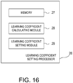
Fig. 16 is a block diagram illustrating a configuration of a learningcoefficient setting processor 26 of an estimating apparatus according to a modification. Similar to the case of the learningcoefficient setting processor 20 of the modification described above, the learningcoefficient setting processor 26 according to this modification sets the learning coefficient η ofEquation 1 which is used by an estimator configured using a neural network. However, the learningcoefficient setting processor 26 according to this modification has a different configuration from the learningcoefficient setting processor 20 of the modification described above. As illustrated inFig. 16 , the learningcoefficient setting processor 26 of this modification has amemory 27, a learningcoefficient calculating module 28, and a learningcoefficient setting module 29.
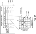
Fig. 17 is a view illustrating a table stored in thememory 27, and learning data stored in association with each cell (each area) of the table. As illustrated inFig. 17 , similar to the case of the modification described above, thememory 27 stores a table sectioned for every particular propeller rotational speed and every particular wind speed and direction in a grid pattern. In this modification, the learning data stored in each area is mapped corresponding to the ground velocity of each learning data. Specifically, as illustrated inFig. 17 , in a map having a plurality of subareas sectioned for every particular ground velocity in the bow direction and every particular ground velocity in the starboard direction in a grid pattern, each learning data is mapped corresponding to the ground velocity.
The learningcoefficient calculating module 28 sets, as the learning coefficient, a value that is obtained by normalizing an inverse of a value calculated by dividing the number of learning data (four in the case ofFig. 17 ) stored in a subarea which includes learning data inputted at a latest timing, by the number of learning data stored in a subarea with a largest number of learning data (ten in a subarea A in the case ofFig. 17 ) among all the subareas of the area having the subarea which includes the learning data inputted at the latest timing. Further, similar to the learningcoefficient setting module 25 of the above modification, the learningcoefficient setting module 29 notifies to the estimator the learning coefficient set by the learningcoefficient calculating module 28 and sets it to be the learning coefficient η inEquation 1. Also with such a configuration, the learning coefficient can suitably be set. - (6)
Fig. 18 is a block diagram illustrating a configuration of an estimating apparatus If according to a modification. The estimating apparatus If according to this modification has a configuration of theestimating apparatus 1a illustrated inFig. 8 , further provided with a learning progressindex deriving module 18.
Fig. 19 is a view illustrating one example of a wind force characteristic chart generated by animage generating module 15, illustrating a deriving process of a learning progress index. The learning progressindex deriving module 18 detects an inclination "a" of a target line L2 illustrated inFig. 19 with respect to a line indicating a fixed log velocity in the starboard direction inFig. 19 (reference line L1). This target line L2 is a straight line coupling a terminal point of the log velocity in a case where wind of a certain speed acts on the first ship from the rear side, to a terminal point of the log velocity in a case where wind of the certain speed acts on the first ship from the front side.
Generally, ships have a left-right symmetric structure. Therefore, it can be considered that if a sufficient number of learning data is acquired, the wind force characteristic chart becomes left-right symmetric. On the other hand, if the number of learning data is insufficient, it can be considered that the wind force characteristic chart inclines asFig. 19 and the inclination a of the target line L2 with respect to the reference line L1 becomes sharper.
In this regard, with theestimating apparatus 1f according to this embodiment, the learning progressindex deriving module 18 detects the inclination a as described above and derives the learning progress index as an index indicating a progress degree of learning according to the degree of this inclination a. As the learning progress index, a numerical value displayed in percentage is given as an example. The learning progressindex deriving module 18 derives the numerical value corresponding to the degree of this inclination a. For example, when the inclination a is sharp (i.e., when the sufficient learning data is considered to have not obtained), the learning progressindex deriving module 18 derives a low numerical value as the learning progress index. On the other hand, when the inclination a is gentle (i.e., when the sufficient learning data is considered to have obtained), the learning progressindex deriving module 18 derives a high numerical value as the learning progress index. The numerical value derived as above is displayed on thedisplay unit 5. It is possible for the user to look at the numerical value and quantitatively grasp reliability of the wind force characteristic chart displayed on thedisplay unit 5.
Note that the learning progress index is not limited to the numerical value displayed in percentage as described above, and may be displayed in a different mode. For example, the learning progress index may be an alphabet ranked into a plurality of levels ("A" indicates high reliability, "B" indicates medium reliability, and "C" indicates low reliability). Alternatively, the learning progress index may be a color on the wind force characteristic chart displayed on the display unit 5 (blue indicates high reliability, yellow indicates medium reliability, and red indicates low reliability). - (7)
Fig. 20 is a block diagram illustrating a configuration of anautopilot system 30. Theautopilot system 30 is configured to automatically control a channel of the first ship by automatically controlling arudder 35 of the first ship. Theautopilot system 30 includes anestimating apparatus 1g and acontroller 31.
The estimatingapparatus 1g has a configuration of theestimating apparatus 1 illustrated inFig. 1 , further provided with adisturbance calculating module 19. Thedisturbance calculating module 19 calculates the velocity (ground velocity) of the first ship caused by disturbance received by the first ship (surface current and wind force) based on a surface current velocity near the first ship which is estimated by the estimatingapparatus 1g, and the wind force propellant velocity obtained from the wind force characteristic chart (the log velocity of the first ship caused by the wind force against the first ship). For example, thedisturbance calculating module 19 calculates the velocity of the first ship caused by the disturbance by adding the surface current velocity and the wind force propellant velocity. Thedisturbance calculating module 19 notifies the velocity of the first ship caused by the disturbance to thecontroller 31.
Thecontroller 31 controls the orientation of therudder 35 so that the first ship travels along a course estimated in advance, based on the positional information of the first ship calculated based on the GPS signals received by theGPS signal receiver 2. Further, thecontroller 31 controls the orientation of therudder 35 also based on the velocity of the first ship caused by the disturbance, which is calculated by thedisturbance calculating module 19.
With the conventional autopilot systems, the orientation of the rudder is controlled based on a first ship position obtained based on GPS signals. In this regard, with theautopilot system 30 illustrated inFig. 20 , the orientation of therudder 35 is controlled based not only on the first ship position obtained based on the GPS signals, but also the disturbance (surface current, wind force, etc.) which influences the first ship position. Thus, it becomes possible to promptly perform suitable steering according to a hydrographic condition. As a result, it becomes possible to travel more accurately along the estimated course. - (8)
Fig. 21 is a block diagram illustrating a configuration of anestimating apparatus 1h according to a modification. In the embodiment and modifications described above, the estimating apparatuses capable of estimating the wind force characteristics as the ship characteristics are raised as examples. Meanwhile, theestimating apparatus 1h according to this modification is configured to be capable of estimating propulsion system characteristics as the ship characteristics. Here, the propulsion system characteristics are characteristics of mechanism components configured to produce a thrust in the ship. Theestimating apparatus 1h according to this embodiment is capable of calculating, as the propulsion system characteristics, the propeller propulsion velocity with respect to the propeller rotational speed. Note that, the propeller propulsion velocity is a log velocity of the ship caused by the rotation of the propeller. - The
estimating apparatus 1h according to this modification includes a surfacecurrent estimating device 8 and a propulsion systemcharacteristic estimating device 9h (ship characteristic estimating device). Since the configuration and operation of the surfacecurrent estimating device 8 are the same as the surfacecurrent estimating device 8 of theestimating apparatus 1 according to the embodiment described above, the description thereof is omitted. - The propulsion system
characteristic estimating device 9h includes aGPS signal receiver 2, apropeller speed detector 3, avane anemometer 4, adata output unit 6a, one or some of components constituting thecalculator 10h (e.g., a groundvelocity calculating module 11, anestimator 12h, a couplingcoefficient updating module 14, and animage generating module 15a), and adisplay unit 5. Since the configurations and operations of theGPS signal receiver 2, the propellerrotational speed detector 3, and thevane anemometer 4 are similar to the case of the surfacecurrent estimating device 8, the description thereof is omitted. - Once the
data output unit 6a receives an instruction signal which is a signal to cause derivation of the propulsion system characteristics of the first ship, it sequentially outputs a plurality of parameter data Dn (n= 1, 2, ...) to theestimator 12h. Each parameter data Dn includes rotational speed data Rn (n= 1, 2, ...) indicating the rotational speed of the propeller and wind velocity vector data VWD1 indicating a wind velocity vector. - In this modification, different from the embodiment described above, the wind velocity vector data VWD1 of the parameter data Dn indicate the same wind velocity vector, whereas the rotational speed data Rn of the parameter data Dn indicate different rotational speeds. In this embodiment, the
data output unit 6 outputs a true wind speed in a bow direction and a true wind speed in a starboard direction, as the wind velocity vector data VWD1. - Note that, the instruction signal S described above is, for example, outputted to the
data output unit 6a upon a suitable operation by a user on a control panel (not illustrated) provided to theestimating apparatus 1h. Here, the user may input a value of a desirable wind velocity vector (e.g., 0 [m/s]) through the control panel. - The
calculator 10h is configured to estimate the propulsion system characteristics based on the parameter data Dn outputted from thedata output unit 6 as described above. Note that since the configurations and operations of the groundvelocity calculating module 11 and the couplingcoefficient updating module 14 ofcalculator 10h are similar to the case of the surfacecurrent estimating device 8 described above, the description thereof is omitted. - As described above, the
estimator 12h is configured to estimate the log velocity of the first ship. Theestimator 12h receives the parameter data Dn outputted from thedata output unit 6a, estimates the values corresponding thereto to be the magnitude |VWTn| of the log velocity VWTn (n= 1, 2, ...), and outputs it as the first output value to theimage generating module 15. - Moreover, the
estimator 12h receives the plurality of parameter data Dn as described above. Further the wind velocity vector data VWD1 of the parameter data Dn indicate the same wind velocity vector, and the rotational speed Rn of the parameter data Dn indicate different propeller rotational speeds. Thus, theestimator 12h outputs the magnitude |VWTn| of the log velocity VWTn when the wind force acts on the first ship is stable and the rotational speed of the propeller varies.Fig. 22 is a view illustrating a correspondence of the plurality of parameter data Dn outputted from thedata output unit 6a, with the magnitudes |VWTn| of the log velocities VWTn estimated based on the parameter data Dn by theestimator 12h, respectively. -
Fig. 23 is a view illustrating one example of a propulsion system characteristic chart generated by theimage generating module 15a. Theimage generating module 15a generates the propulsion system characteristic chart indicated by the solid line ofFig. 23 . For example, theimage generating module 15a plots on coordinates illustrated inFig. 23 (the vertical axis indicates the magnitude of the log velocity and the horizontal axis indicates the rotational speed of the propeller) points defined by the propeller propulsion velocity |VWTn| which is the magnitude of the log velocity VWTn outputted from theestimator 12h, and the rotational speed Rn used in estimating the log velocity VWTn. Further, theimage generating module 15a calculates, by using regression analysis etc., a curve (propulsion system characteristics) indicated by the solid line ofFig. 23 , based on the plurality of plotted points. Moreover, this propulsion system characteristic chart is displayed on thedisplay unit 5. - Generally, the propulsion system characteristics are ideal characteristics in trial for a new ship or immediately after repairing, for example, characteristics with which the propeller propulsion velocity with respect to the propeller rotational speed becomes higher (see the dashed line of
Fig. 23 ). Therefore, for example, by comparing the propulsion system characteristics in trial for a new ship with the propulsion system characteristics of the first ship at a current time point, it is possible to estimate a deteriorated state of an engine, a stain state of a ship body surface, etc. By knowing these states, it is possible for the user to determine a more accurate operation plan, necessity of abnormality checkup, etc. - As described above, with the propulsion system
characteristic estimating device 9h of theestimating apparatus 1h according to this modification, when stable wind force acts on the first ship, it is possible to estimate the change of the log velocity of the first ship caused by the propeller rotational speed. - Therefore, according to the propulsion system
characteristic estimating device 9h, it is possible to easily grasp the relationship between the propeller rotational speed which is one of the parameters which influence the log velocity of the first ship, and the log velocity of the first ship caused by the rotational speed. - Further, with the propulsion system
characteristic estimating device 9h, theestimator 12h is configured by using the neural network. Thus, it is possible to suitably configure theestimator 12 capable of outputting the log velocity. - Further, with the propulsion system
characteristic estimating device 9h, theestimator 12h is updated to reduce the error of each second output value of theestimator 12h with respect to the ground velocity calculated by the groundvelocity calculating module 11. Thus, it is possible to configure theestimator 12h provided with the learning function. Additionally, since the propulsion systemcharacteristic estimating device 9h is capable of accumulating a large amount of data required for estimating an accurate log velocity during the travel, it is possible to omit works of preparing these multiple learning data (data of a ground velocity under a certain condition) in advance and setting a suitable coupling coefficient based on these learning data. - (9)
Fig. 24 is a block diagram illustrating a configuration of anestimating apparatus 1i according to a modification. Acalculator 10i of theestimating apparatus 1i according to this modification is different from thecalculator 10h illustrated inFig. 21 , and has a configuration in which the surface current calculatingmodule 13 is omitted. That is, theestimating apparatus 1i according to this modification does not have a function as the surfacecurrent estimating device 8, and is provided as a propulsion systemcharacteristic estimating device 9h. Therefore, in accordance with theestimating apparatus 1i according to this modification, different from the case of the modification illustrated inFig. 21 , the surface current near the first ship cannot be estimated, whereas similarly to the case of the modification illustrated inFig. 21 , it is possible to estimate the propulsion system characteristics of the first ship.
Note that, the respective modifications described as modifications of theestimating apparatus 1 according to the embodiment described above may suitably applied to either of the modifications illustrated inFigs. 21 and24 . Further, by suitably combining theestimating apparatus 1 according to the embodiment described above with the estimating apparatus illustrated inFig. 21 or24 , an estimating apparatus capable of estimating the surface current velocity near the first ship, the wind force characteristics of the first ship, and the propulsion system characteristics of the first ship may be configured. - (10) In the modification illustrated in
Fig. 21 , by displaying the propulsion system characteristic chart on thedisplay unit 5, although the state of the propulsion system at the current time point is notified to the user, it is not limited to this. For example, the display unit may also display an index indicating the deteriorated state of the propulsion system.
Fig. 25 is a view illustrating one example of arotational speed meter 7 displayed on the display unit. Therotational speed meter 7 is provided with ascale portion 7a on which numerical values of the rotational speed are indicated, and configured so that anindication pointer 7b indicates the rotational speed of the propeller.
Further in this embodiment, the color of theindication pointer 7b functions as the index indicating the deteriorated state of the propulsion system. For example, in a state where the propulsion system is not deteriorated, the color of theindication pointer 7b is displayed, for example, in blue (no hatching) as illustrated in Part (A) ofFig. 25 . Moreover, in a state where the propulsion system is slightly deteriorated, the color of theindication pointer 7b is displayed, for example, in yellow (hatched with wide gaps) as illustrated in Part (B) ofFig. 25 . Furthermore, in a state where the propulsion system is greatly deteriorated and in need of repairing, the color of theindication pointer 7b is displayed, for example, in red (hatched with narrow gaps) as illustrated in Part (C) ofFig. 25 . Thus, it is possible for the user to easily, visually recognize the deterioration of the propulsion system characteristics.
The deteriorated state of the propulsion system characteristics described above may be determined, for example, based on a ratio between the propeller propulsion velocity at a particular speed of the propulsion system in trial for a new ship or immediately after repairing, and the propeller propulsion velocity at a particular speed of the propulsion system at the current time point.
Note that, as the index indicating the deteriorated state of the propulsion system, without limiting to the colors as described above, for example, a pattern corresponding to the deteriorated state may be applied, or brightness of therotational speed meter 7 may gradually be lowered according to the deteriorated state. - (11)
Fig. 26 is a block diagram illustrating a configuration of anestimating apparatus 1j according to a modification. Theestimating apparatus 1j according to this modification has a configuration of theestimating apparatus 1i illustrated inFig. 24 , further provided with a learning progressindex deriving module 18a.
Fig. 27 is a view illustrating one example of the propulsion system characteristic chart generated by theimage generating module 15a, illustrating the learning progress index.
The propulsion system characteristic chart is a chart indicating the propeller propulsion velocity of the first ship when the propeller rotational speed is changed. Therefore, when the propeller rotational speed is zero, the propeller propulsion velocity should ideally become zero. Thus, it is considered that if a sufficient number of learning data is acquired, in the propulsion system characteristic chart, the propeller propulsion velocity when the propeller rotational speed is zero comes close to zero. On the other hand, it is considered that if the sufficient number of learning data is not acquired, the value of the propeller propulsion velocity when the propeller rotational speed is zero ("b" inFig. 27 ) becomes high.
In this regard, in theestimating apparatus 1j according to this embodiment, the learning progressindex deriving module 18 detects the value of the propeller propulsion velocity b illustrated inFig. 27 and derives, as the learning progress index, the numerical value according to the magnitude of the propeller propulsion velocity b. For example, the learning progressindex deriving module 18 derives, as the learning progress index, the value of the propeller propulsion velocity b, and displays it on thedisplay unit 5. It is possible for the user to look at the numerical value and quantitatively grasp reliability of the propulsion systems characteristic chart displayed on thedisplay unit 5.
Note that the learning progress index is not limited to the propeller propulsion velocity b as described above, and may be displayed in a different mode. For example, the learning progress index may be an alphabet ranked into a plurality of levels ("A" indicates high reliability, "B" indicates medium reliability, and "C" indicates low reliability). Alternatively, the learning progress index may be a color of the propulsion system characteristic chart displayed on the display unit 5 (blue indicates high reliability, yellow indicates medium reliability, and red indicates low reliability). - (12) In each of the embodiment and modifications described above, the
display unit 5 displays the wind force characteristics (seeFig. 7 ) or the propulsion system characteristics (Fig. 27 ); however, for example, thedisplay unit 5 may display the first ship position after a particular period of time from a current time point.
Fig. 28 is one example of a map displayed on thedisplay unit 5 of the estimating apparatus according to this modification, indicating the position of the first ship after the particular time period. The current location of the first ship and an estimated position of the first ship after the particular time period are displayed on the map illustrated inFig. 28 . In the example illustrated inFig. 28 , the terminal point of the arrow indicates the first ship position P after the particular time period when the propeller of the first ship keeps rotating at a certain rotational speed. Further, the oval-like closed curve illustrated inFig. 28 indicates a possible drift of the first ship from the position P by the wind force against the first ship. For example, the point P1 indicates the first ship position in the case where the wind at a velocity VWD3 [m/s] keeps acting on the first ship from the left direction thereof. Therefore, according to this modification, it is possible to accurately predict a future position of the first ship in consideration of the velocity of the wind force which acts on the first ship.
Note that, in predicting the future position of the first ship, other than the wind force characteristics described above, the velocity of the surface current near the first ship calculated by the estimatingapparatus 1 illustrated inFig. 1 , the propulsion system characteristics estimated by theestimating apparatus 1h illustrated inFig. 21 , etc. may be taken into consideration. Thus, it is possible to predict the future position of the first ship more accurately. - (13) Moreover, in each of the embodiment and modifications described above, if the accumulation of learning data is not sufficient, the learning data may be complemented.
-
Fig. 29 is a schematic view illustrating complement of the learning data. Since a ship has a substantially laterally symmetrical shape, the wind force characteristics are estimated to be laterally symmetric as well. Specifically, for example, between a case where a ship traveling under a certain condition receives wind from the port quarter at an angle of 45 degrees and a case where the ship receives wind from the starboard quarter at an angle of 45 degrees (wind velocities are the same), the traveling directions are estimated to be laterally symmetric. Therefore, with reference toFig. 29 , for example, in a case where the propeller rotational speed is a particular speed, the wind direction is on the port quarter at the angle of 45 degrees, and the wind speed is a particular speed, if the ground velocity is VG, the data may be complemented as follows based on learning data thereof. For example, as learning data for when the propeller rotational speed and the wind speed are the same as the learning data of the above case and the wind direction is on the starboard quarter at an angle of 45 degrees, a laterally inverted vector V'G may be complemented. By complementing the learning data as above, for example, even in an initial stage where the accumulation of learning data is insufficient, it is possible to accurately estimate a surface current, wind force characteristics, propulsion system characteristics, etc. -
- 6, 6a Data Output Unit
- 9, 9b, 9c, 9d, 9e, 9f Wind Force Characteristic Estimating Device (Ship Characteristic Estimating Device)
- 9h, 9j Propulsion System Characteristic Estimating Device (Ship Characteristic Estimating Device)
- 12, 12c, 12d, 12h Estimator
Claims (8)
- A ship characteristic estimating device (9), comprising:a data output unit (6) configured to output a plurality of parameter data respectively including rotational speed data indicating a rotational speed of a propeller of a ship, and wind velocity vector data indicating a wind velocity vector of wind force that may act on the ship; andan estimator (12) configured to receive the plurality of parameter data outputted from the data output unit (6), estimate values corresponding to the respective parameter data to be log velocity vectors of the ship, and output the log velocity vectors as first output values,wherein the rotational speed data included in the plurality of parameter data indicate the same rotational speed,wherein the wind velocity vector data included in the plurality of parameter data indicate different wind velocity vectors, andwherein each of the first output values is estimated and outputted as the log velocity vector of the ship when the ship travels at the rotational speed indicated by the rotational speed data.
- A ship characteristic estimating device (9), comprising:a data output unit (6) configured to output a plurality of parameter data respectively including rotational speed data indicating a rotational speed of a propeller of a ship, and wind velocity vector data indicating a wind velocity vector of wind force that may act on the ship; andan estimator (12) configured to receive the plurality of parameter data outputted from the data output unit (6), estimate values corresponding to the respective parameter data to be log velocity vectors of the ship, and output the log velocity vectors as first output values,wherein the rotational speed data included in the plurality of parameter data indicate different rotational speeds,wherein the wind velocity vector data included in the plurality of parameter data indicate the same wind velocity vector, andwherein each of the first output values is estimated and outputted as the log velocity vector of the ship when the wind velocity vector indicated by the wind velocity vector data acts on the ship.
- The ship characteristic estimating device (9) of claim 1 or 2, wherein the estimator (12) is configured by using a neural network,
wherein the estimator (12) has:at least two input units (UIN_1, UIN_2, UIN_3), respectively configured to receive one of the rotational speed data and the wind velocity vector data; andan output unit (UOUT_1, UOUT_2) configured to output the first output value, andwherein values outputted from the input units (UIN_1, UIN_2, UIN_3) of the neural network are multiplied by a coupling coefficient and then transmitted to the output unit (UOUT_1, UOUT_2). - The ship characteristic estimating device (9) of claim 3, further comprising:a ground velocity calculating module (11) configured to calculate a ground velocity vector of the ship traveling on water;a propeller speed detector (3) configured to detect the rotational speed of the propeller; anda vane anemometer (4) equipped in the ship and configured to measure the wind velocity vector of the wind force against the ship,wherein each of the input units (UIN_1, UIN_2, UIN_3) receives one of the rotational speed of the propeller detected by the propeller speed detector (3), and the wind velocity vector measured by the vane anemometer (4),wherein the output unit (UOUT_1, UOUT_2) estimates, as the log velocity vector of the ship, a value corresponding to a condition defined by a combination of the rotational speed of the propeller detected by the propeller speed detector (3) and the wind velocity vector measured by the vane anemometer (4), and outputs the value as a second output value, andfurther comprising an updating module (14) configured to compare the second output value with the ground velocity vector calculated as a teaching signal by the ground velocity calculating module (11), and update the coupling coefficient to reduce an error between the second output value and the teaching signal.
- The ship characteristic estimating device (9c) of claim 1 or 2, wherein the estimator (12c) has a memory (16) including a plurality of cells (16a) respectively configured to store the ground velocity vector of the ship under one of a plurality of conditions defined by a combination of the rotational speed of the propeller of the ship and the wind velocity vector of the wind force against the ship for every one of the plurality of conditions, and the estimator (12c) outputs, as the first output value, an average value of the ground velocity vectors stored in the cells (16a) specified by the condition corresponding to the combination of the rotational speed data and the wind velocity vector data included in the received parameter data.
- The ship characteristic estimating device (9c) of claim 5, further comprising:a ground velocity calculating module (11) configured to calculate a ground velocity vector of the ship traveling on water;a propeller speed detector (3) configured to detect the rotational speed of the propeller; anda vane anemometer (4) equipped in the ship and configured to measure the wind velocity vector of the wind force against the ship,wherein the memory (16) further includes an updating module configured to store the ground velocity vector calculated by the ground velocity calculating module (11) in the cell (16a) specified by a combination of the rotational speed detected by the propeller speed detector (3) and the wind velocity vector measured by the vane anemometer (4) when data required for calculating the ground velocity vector is acquired.
- The ship characteristic estimating device (9, 9b, 9c, 9d, 9e, 9f) of any one of claims 1 to 6, further comprising a display unit (5) configured to display a range where the ship is predicted to be located therein after a particular period of time from a current time point, based on the first output value outputted from the estimator (12, 12c, 12d, 12h).
- An autopilot system (30), comprising:a GNSS signal receiver (2) equipped in a ship and configured to receive GNSS signals; anda controller (31) configured to control a rudder angle of the ship based on positional information of the ship that is calculated based on GNSS signals received by the GNSS signal receiver (2),further comprising the ship characteristic estimating device (9) of any one of claims 1 to 7,wherein the controller (31) controls the rudder angle of the ship based also on the first output value outputted from the estimator (12) of the ship characteristic estimating device (9).
Applications Claiming Priority (2)
| Application Number | Priority Date | Filing Date | Title |
|---|---|---|---|
| JP2014152621 | 2014-07-28 | ||
| PCT/JP2015/068995 WO2016017358A1 (en) | 2014-07-28 | 2015-07-01 | Signal processing device, transponder device, radar device, and signal processing method |
Publications (3)
| Publication Number | Publication Date |
|---|---|
| EP3176068A1 true EP3176068A1 (en) | 2017-06-07 |
| EP3176068A4 EP3176068A4 (en) | 2018-01-24 |
| EP3176068B1 EP3176068B1 (en) | 2023-03-29 |
Family
ID=55217262
Family Applications (1)
| Application Number | Title | Priority Date | Filing Date |
|---|---|---|---|
| EP15826886.2A Active EP3176068B1 (en) | 2014-07-28 | 2015-07-01 | Vessel characteristic estimation device and automatic steering device |
Country Status (5)
| Country | Link |
|---|---|
| US (1) | US10137972B2 (en) |
| EP (1) | EP3176068B1 (en) |
| JP (1) | JP6513677B2 (en) |
| CN (1) | CN106660613B (en) |
| WO (1) | WO2016017358A1 (en) |
Cited By (1)
| Publication number | Priority date | Publication date | Assignee | Title |
|---|---|---|---|---|
| US12584745B2 (en) | 2022-07-22 | 2026-03-24 | Navico, Inc. | Dynamic easyrouting utilizing onboard sensors |
Families Citing this family (22)
| Publication number | Priority date | Publication date | Assignee | Title |
|---|---|---|---|---|
| CN106184612B (en) * | 2016-08-11 | 2018-07-20 | 广船国际有限公司 | A kind of localization method of radar mast above-water hoisting |
| DE102017209667A1 (en) * | 2016-12-12 | 2018-06-14 | Continental Automotive Gmbh | Storage of velocity information for the prediction of the future velocity trajectory |
| RU186066U1 (en) * | 2017-11-30 | 2018-12-28 | Федеральное государственное автономное образовательное учреждение высшего образования "Крымский федеральный университет имени В.И. Вернадского" | Unmanned aerial vehicle driving engine control device |
| US11080438B2 (en) * | 2018-05-30 | 2021-08-03 | International Business Machines Corporation | Building-information management system with directional wind propagation and diffusion |
| US11243957B2 (en) * | 2018-07-10 | 2022-02-08 | Verizon Patent And Licensing Inc. | Self-organizing maps for adaptive individualized user preference determination for recommendation systems |
| CN109884886B (en) * | 2019-03-29 | 2021-09-28 | 大连海事大学 | Ship motion model-free adaptive optimal control method based on width learning |
| JP7263150B2 (en) | 2019-06-27 | 2023-04-24 | 古野電気株式会社 | Hull control device, hull control method, and hull control program |
| JP7261105B2 (en) | 2019-06-28 | 2023-04-19 | 古野電気株式会社 | Hull control device, hull control method, and hull control program |
| JP7263158B2 (en) | 2019-07-05 | 2023-04-24 | 古野電気株式会社 | Hull control device, hull control method, and hull control program |
| JP7544470B2 (en) * | 2019-09-13 | 2024-09-03 | 古野電気株式会社 | Hull control device, hull control method, and hull control program |
| CN111381595B (en) * | 2020-03-10 | 2023-07-25 | 大连海事大学 | Ship dynamic positioning method based on event triggering |
| CN115379985A (en) * | 2020-04-01 | 2022-11-22 | 古野电气株式会社 | Data format converter, navigation system, data format conversion method, and data format conversion program |
| EP4235622B1 (en) * | 2020-10-26 | 2025-11-19 | Furuno Electric Co., Ltd. | Ship monitoring system, ship monitoring method, information processing device, and program |
| US12459618B2 (en) | 2021-12-22 | 2025-11-04 | Navico, Inc. | Device for steering a trolling motor and method of the same |
| US12461495B2 (en) | 2022-05-17 | 2025-11-04 | Furuno Electric Co., Ltd. | Disturbance estimating apparatus, method, and computer program |
| US12208869B2 (en) | 2022-06-15 | 2025-01-28 | Furuno Electric Co., Ltd. | Disturbance estimating apparatus, method, and computer program |
| US12392613B2 (en) * | 2022-06-15 | 2025-08-19 | Furuno Electric Co., Ltd. | Disturbance estimating apparatus, method, and computer program |
| CN115047889B (en) * | 2022-08-15 | 2022-11-04 | 北京海兰信数据科技股份有限公司 | Method and system for determining course control effect of autopilot |
| CN115327669B (en) * | 2022-08-22 | 2024-10-15 | 国家海洋技术中心 | Sea surface wind field inversion method and device |
| WO2024088508A1 (en) * | 2022-10-24 | 2024-05-02 | Huawei Digital Power Technologies Co., Ltd. | Method for estimating the longitudinal velocity of a vehicle and vehicle control unit |
| CN118928739A (en) * | 2024-08-13 | 2024-11-12 | 广州海工船舶设备有限公司 | A novel ship azimuth propeller stepping steering control system and method |
| CN118795910B (en) * | 2024-09-12 | 2024-11-15 | 北京世航智能科技有限公司 | A method and system for controlling the depth of an underwater robot |
Family Cites Families (14)
| Publication number | Priority date | Publication date | Assignee | Title |
|---|---|---|---|---|
| US3881094A (en) | 1973-07-05 | 1975-04-29 | Velcon Filters | Signal for evaluating sailboat performance |
| JPH08233595A (en) * | 1995-02-27 | 1996-09-13 | Fuji Royal:Kk | Display device of navigation information |
| JP2002316692A (en) | 2001-04-24 | 2002-10-29 | Mitsui Eng & Shipbuild Co Ltd | Remote management system for equipment mounted on transportation equipment |
| JP2003344437A (en) * | 2002-05-27 | 2003-12-03 | Yamaha Motor Co Ltd | Ground speed calculation method and ground speed calculation device |
| US8824239B2 (en) * | 2004-03-17 | 2014-09-02 | Westerngeco L.L.C. | Marine seismic survey method and system |
| KR100868849B1 (en) * | 2007-01-30 | 2008-11-14 | 현대중공업 주식회사 | How to Select the Optimal Course for Ship Speed Test |
| EP2192385A1 (en) * | 2008-11-26 | 2010-06-02 | Nederlandse Organisatie voor toegepast- natuurwetenschappelijk onderzoek TNO | Signal processing module, navigation device with the signal processing module, vehicle provided with a navigation device and method of providing navigation data |
| JP5435418B2 (en) * | 2009-03-19 | 2014-03-05 | 独立行政法人海上技術安全研究所 | Ocean current data assimilation method and system |
| JP5033210B2 (en) | 2010-03-31 | 2012-09-26 | 三井造船株式会社 | Ship main engine control system and method |
| JP2011220844A (en) * | 2010-04-09 | 2011-11-04 | Seiko Epson Corp | Position calculation method and position calculation device |
| US8219267B2 (en) * | 2010-05-27 | 2012-07-10 | Honeywell International Inc. | Wind estimation for an unmanned aerial vehicle |
| US20140046510A1 (en) * | 2012-08-13 | 2014-02-13 | Lockheed Martin Corporation | Estimating a wind vector |
| WO2015045117A1 (en) * | 2013-09-27 | 2015-04-02 | 日本郵船株式会社 | Data processing device for generating data indicating navigation performance of ship, program, storage medium, and data processing method |
| DK2860395T3 (en) * | 2013-10-09 | 2017-11-13 | Siemens Ag | Automatic power estimation adjustment system |
-
2015
- 2015-07-01 US US15/329,728 patent/US10137972B2/en active Active
- 2015-07-01 EP EP15826886.2A patent/EP3176068B1/en active Active
- 2015-07-01 JP JP2016538234A patent/JP6513677B2/en not_active Expired - Fee Related
- 2015-07-01 WO PCT/JP2015/068995 patent/WO2016017358A1/en not_active Ceased
- 2015-07-24 CN CN201580040234.1A patent/CN106660613B/en not_active Expired - Fee Related
Cited By (1)
| Publication number | Priority date | Publication date | Assignee | Title |
|---|---|---|---|---|
| US12584745B2 (en) | 2022-07-22 | 2026-03-24 | Navico, Inc. | Dynamic easyrouting utilizing onboard sensors |
Also Published As
| Publication number | Publication date |
|---|---|
| US20170233051A1 (en) | 2017-08-17 |
| WO2016017358A1 (en) | 2016-02-04 |
| CN106660613A (en) | 2017-05-10 |
| CN106660613B (en) | 2019-02-05 |
| WO2016017358A8 (en) | 2017-02-16 |
| EP3176068A4 (en) | 2018-01-24 |
| US10137972B2 (en) | 2018-11-27 |
| JPWO2016017358A1 (en) | 2018-04-05 |
| EP3176068B1 (en) | 2023-03-29 |
| JP6513677B2 (en) | 2019-05-15 |
| WO2016017358A9 (en) | 2017-05-11 |
Similar Documents
| Publication | Publication Date | Title |
|---|---|---|
| EP3176068B1 (en) | Vessel characteristic estimation device and automatic steering device | |
| EP3388327B1 (en) | Route setting method for underwater vehicle, underwater vehicle optimum control method using same, and underwater vehicle | |
| US8326472B2 (en) | Automatic vessel position holding control method and controller | |
| CN110794855A (en) | Comprehensive control system and method for underwater robot | |
| FI123871B (en) | Procedures and systems for measuring movements in six degrees of freedom | |
| EP3112877B1 (en) | Surface current estimation device, surface current estimation system, ocean model estimation device, and risk determination device | |
| JP2020158072A (en) | Vessel performance estimation method and vessel performance estimation system by assimilation of data | |
| WO2016098491A1 (en) | Optimum rotation speed estimation device, optimum rotation speed estimation system, and rotation speed control device | |
| JP6154540B2 (en) | Ship characteristic estimation device | |
| US20250026458A1 (en) | Method for assisting with guiding a surface vessel for towing an underwater device by means of a cable | |
| JP5296736B2 (en) | Incidence wave height and wave direction estimation method, automatic channel or / and ship position maintaining control method, automatic channel or / and ship position maintaining control system, and ship and offshore structure | |
| JP4260612B2 (en) | Tidal current estimation method and apparatus, and navigation vehicle control method and apparatus using the same | |
| JP2023183382A (en) | Disturbance estimation device, disturbance estimation method, and disturbance estimation program | |
| JP2019090645A (en) | Log speed estimation device, log speed display device, periodic current measuring device, automatic navigation device, and method for estimating log speed | |
| US12503207B1 (en) | Marine propulsion control system and method with proximity-based velocity limiting | |
| RU2564786C1 (en) | Control over ship move with compensated slowly-varying external disturbances and ship control system to this end | |
| Hamad et al. | A Survey of Positioning Systems for Ships Based on New Categories | |
| JP2023131821A (en) | Hull condition estimation device, hull condition estimation system, hull condition estimation method, and hull condition estimation program | |
| CN121894128A (en) | A trans-medium air-sea vehicle and its control method | |
| ARANDA et al. | An overview about dynamic positioning of ships | |
| JP2016114478A (en) | Flow velocity difference estimation device | |
| Hernández Cuesta et al. | An Overview about Dynamic Positioning of Ships | |
| Pascual et al. | SINOCOP EXPERIMENT: BALEARIC SEA 2009 | |
| HK1256375B (en) | Apparatus for predicting a power consumption of a maritime vessel |
Legal Events
| Date | Code | Title | Description |
|---|---|---|---|
| STAA | Information on the status of an ep patent application or granted ep patent |
Free format text: STATUS: THE INTERNATIONAL PUBLICATION HAS BEEN MADE |
|
| 17P | Request for examination filed |
Effective date: 20170126 |
|
| AK | Designated contracting states |
Kind code of ref document: A1 Designated state(s): AL AT BE BG CH CY CZ DE DK EE ES FI FR GB GR HR HU IE IS IT LI LT LU LV MC MK MT NL NO PL PT RO RS SE SI SK SM TR |
|
| AX | Request for extension of the european patent |
Extension state: BA ME |
|
| PUAI | Public reference made under article 153(3) epc to a published international application that has entered the european phase |
Free format text: ORIGINAL CODE: 0009012 |
|
| STAA | Information on the status of an ep patent application or granted ep patent |
Free format text: STATUS: REQUEST FOR EXAMINATION WAS MADE |
|
| DAV | Request for validation of the european patent (deleted) | ||
| DAX | Request for extension of the european patent (deleted) | ||
| A4 | Supplementary search report drawn up and despatched |
Effective date: 20180104 |
|
| RIC1 | Information provided on ipc code assigned before grant |
Ipc: B63H 25/04 20060101ALI20171218BHEP Ipc: G01P 5/00 20060101ALI20171218BHEP Ipc: B63B 9/00 20060101AFI20171218BHEP |
|
| STAA | Information on the status of an ep patent application or granted ep patent |
Free format text: STATUS: EXAMINATION IS IN PROGRESS |
|
| 17Q | First examination report despatched |
Effective date: 20190417 |
|
| REG | Reference to a national code |
Ref country code: DE Ref legal event code: R079 Ref document number: 602015082981 Country of ref document: DE Free format text: PREVIOUS MAIN CLASS: B63B0009000000 Ipc: G01P0005000000 |
|
| GRAP | Despatch of communication of intention to grant a patent |
Free format text: ORIGINAL CODE: EPIDOSNIGR1 |
|
| STAA | Information on the status of an ep patent application or granted ep patent |
Free format text: STATUS: GRANT OF PATENT IS INTENDED |
|
| RIC1 | Information provided on ipc code assigned before grant |
Ipc: B63B 79/40 20200101ALI20220930BHEP Ipc: B63B 79/30 20200101ALI20220930BHEP Ipc: B63B 79/15 20200101ALI20220930BHEP Ipc: B63H 25/04 20060101ALI20220930BHEP Ipc: G01P 5/00 20060101AFI20220930BHEP |
|
| INTG | Intention to grant announced |
Effective date: 20221024 |
|
| GRAS | Grant fee paid |
Free format text: ORIGINAL CODE: EPIDOSNIGR3 |
|
| GRAA | (expected) grant |
Free format text: ORIGINAL CODE: 0009210 |
|
| STAA | Information on the status of an ep patent application or granted ep patent |
Free format text: STATUS: THE PATENT HAS BEEN GRANTED |
|
| AK | Designated contracting states |
Kind code of ref document: B1 Designated state(s): AL AT BE BG CH CY CZ DE DK EE ES FI FR GB GR HR HU IE IS IT LI LT LU LV MC MK MT NL NO PL PT RO RS SE SI SK SM TR |
|
| REG | Reference to a national code |
Ref country code: GB Ref legal event code: FG4D |
|
| REG | Reference to a national code |
Ref country code: CH Ref legal event code: EP |
|
| REG | Reference to a national code |
Ref country code: DE Ref legal event code: R096 Ref document number: 602015082981 Country of ref document: DE |
|
| REG | Reference to a national code |
Ref country code: AT Ref legal event code: REF Ref document number: 1557054 Country of ref document: AT Kind code of ref document: T Effective date: 20230415 |
|
| REG | Reference to a national code |
Ref country code: IE Ref legal event code: FG4D |
|
| P01 | Opt-out of the competence of the unified patent court (upc) registered |
Effective date: 20230523 |
|
| REG | Reference to a national code |
Ref country code: LT Ref legal event code: MG9D |
|
| PG25 | Lapsed in a contracting state [announced via postgrant information from national office to epo] |
Ref country code: RS Free format text: LAPSE BECAUSE OF FAILURE TO SUBMIT A TRANSLATION OF THE DESCRIPTION OR TO PAY THE FEE WITHIN THE PRESCRIBED TIME-LIMIT Effective date: 20230329 Ref country code: NO Free format text: LAPSE BECAUSE OF FAILURE TO SUBMIT A TRANSLATION OF THE DESCRIPTION OR TO PAY THE FEE WITHIN THE PRESCRIBED TIME-LIMIT Effective date: 20230629 Ref country code: LV Free format text: LAPSE BECAUSE OF FAILURE TO SUBMIT A TRANSLATION OF THE DESCRIPTION OR TO PAY THE FEE WITHIN THE PRESCRIBED TIME-LIMIT Effective date: 20230329 Ref country code: LT Free format text: LAPSE BECAUSE OF FAILURE TO SUBMIT A TRANSLATION OF THE DESCRIPTION OR TO PAY THE FEE WITHIN THE PRESCRIBED TIME-LIMIT Effective date: 20230329 Ref country code: HR Free format text: LAPSE BECAUSE OF FAILURE TO SUBMIT A TRANSLATION OF THE DESCRIPTION OR TO PAY THE FEE WITHIN THE PRESCRIBED TIME-LIMIT Effective date: 20230329 |
|
| PGFP | Annual fee paid to national office [announced via postgrant information from national office to epo] |
Ref country code: FR Payment date: 20230608 Year of fee payment: 9 |
|
| REG | Reference to a national code |
Ref country code: NL Ref legal event code: MP Effective date: 20230329 |
|
| REG | Reference to a national code |
Ref country code: AT Ref legal event code: MK05 Ref document number: 1557054 Country of ref document: AT Kind code of ref document: T Effective date: 20230329 |
|
| PG25 | Lapsed in a contracting state [announced via postgrant information from national office to epo] |
Ref country code: SE Free format text: LAPSE BECAUSE OF FAILURE TO SUBMIT A TRANSLATION OF THE DESCRIPTION OR TO PAY THE FEE WITHIN THE PRESCRIBED TIME-LIMIT Effective date: 20230329 Ref country code: NL Free format text: LAPSE BECAUSE OF FAILURE TO SUBMIT A TRANSLATION OF THE DESCRIPTION OR TO PAY THE FEE WITHIN THE PRESCRIBED TIME-LIMIT Effective date: 20230329 Ref country code: GR Free format text: LAPSE BECAUSE OF FAILURE TO SUBMIT A TRANSLATION OF THE DESCRIPTION OR TO PAY THE FEE WITHIN THE PRESCRIBED TIME-LIMIT Effective date: 20230630 Ref country code: FI Free format text: LAPSE BECAUSE OF FAILURE TO SUBMIT A TRANSLATION OF THE DESCRIPTION OR TO PAY THE FEE WITHIN THE PRESCRIBED TIME-LIMIT Effective date: 20230329 |
|
| PG25 | Lapsed in a contracting state [announced via postgrant information from national office to epo] |
Ref country code: SM Free format text: LAPSE BECAUSE OF FAILURE TO SUBMIT A TRANSLATION OF THE DESCRIPTION OR TO PAY THE FEE WITHIN THE PRESCRIBED TIME-LIMIT Effective date: 20230329 Ref country code: RO Free format text: LAPSE BECAUSE OF FAILURE TO SUBMIT A TRANSLATION OF THE DESCRIPTION OR TO PAY THE FEE WITHIN THE PRESCRIBED TIME-LIMIT Effective date: 20230329 Ref country code: PT Free format text: LAPSE BECAUSE OF FAILURE TO SUBMIT A TRANSLATION OF THE DESCRIPTION OR TO PAY THE FEE WITHIN THE PRESCRIBED TIME-LIMIT Effective date: 20230731 Ref country code: ES Free format text: LAPSE BECAUSE OF FAILURE TO SUBMIT A TRANSLATION OF THE DESCRIPTION OR TO PAY THE FEE WITHIN THE PRESCRIBED TIME-LIMIT Effective date: 20230329 Ref country code: EE Free format text: LAPSE BECAUSE OF FAILURE TO SUBMIT A TRANSLATION OF THE DESCRIPTION OR TO PAY THE FEE WITHIN THE PRESCRIBED TIME-LIMIT Effective date: 20230329 Ref country code: AT Free format text: LAPSE BECAUSE OF FAILURE TO SUBMIT A TRANSLATION OF THE DESCRIPTION OR TO PAY THE FEE WITHIN THE PRESCRIBED TIME-LIMIT Effective date: 20230329 |
|
| PGFP | Annual fee paid to national office [announced via postgrant information from national office to epo] |
Ref country code: GB Payment date: 20230608 Year of fee payment: 9 |
|
| PG25 | Lapsed in a contracting state [announced via postgrant information from national office to epo] |
Ref country code: SK Free format text: LAPSE BECAUSE OF FAILURE TO SUBMIT A TRANSLATION OF THE DESCRIPTION OR TO PAY THE FEE WITHIN THE PRESCRIBED TIME-LIMIT Effective date: 20230329 Ref country code: PL Free format text: LAPSE BECAUSE OF FAILURE TO SUBMIT A TRANSLATION OF THE DESCRIPTION OR TO PAY THE FEE WITHIN THE PRESCRIBED TIME-LIMIT Effective date: 20230329 Ref country code: IS Free format text: LAPSE BECAUSE OF FAILURE TO SUBMIT A TRANSLATION OF THE DESCRIPTION OR TO PAY THE FEE WITHIN THE PRESCRIBED TIME-LIMIT Effective date: 20230729 |
|
| PGFP | Annual fee paid to national office [announced via postgrant information from national office to epo] |
Ref country code: DE Payment date: 20230613 Year of fee payment: 9 |
|
| REG | Reference to a national code |
Ref country code: DE Ref legal event code: R097 Ref document number: 602015082981 Country of ref document: DE |
|
| PG25 | Lapsed in a contracting state [announced via postgrant information from national office to epo] |
Ref country code: DK Free format text: LAPSE BECAUSE OF FAILURE TO SUBMIT A TRANSLATION OF THE DESCRIPTION OR TO PAY THE FEE WITHIN THE PRESCRIBED TIME-LIMIT Effective date: 20230329 Ref country code: CZ Free format text: LAPSE BECAUSE OF FAILURE TO SUBMIT A TRANSLATION OF THE DESCRIPTION OR TO PAY THE FEE WITHIN THE PRESCRIBED TIME-LIMIT Effective date: 20230329 |
|
| PLBE | No opposition filed within time limit |
Free format text: ORIGINAL CODE: 0009261 |
|
| STAA | Information on the status of an ep patent application or granted ep patent |
Free format text: STATUS: NO OPPOSITION FILED WITHIN TIME LIMIT |
|
| PG25 | Lapsed in a contracting state [announced via postgrant information from national office to epo] |
Ref country code: MC Free format text: LAPSE BECAUSE OF FAILURE TO SUBMIT A TRANSLATION OF THE DESCRIPTION OR TO PAY THE FEE WITHIN THE PRESCRIBED TIME-LIMIT Effective date: 20230329 |
|
| PG25 | Lapsed in a contracting state [announced via postgrant information from national office to epo] |
Ref country code: MC Free format text: LAPSE BECAUSE OF FAILURE TO SUBMIT A TRANSLATION OF THE DESCRIPTION OR TO PAY THE FEE WITHIN THE PRESCRIBED TIME-LIMIT Effective date: 20230329 |
|
| REG | Reference to a national code |
Ref country code: CH Ref legal event code: PL |
|
| 26N | No opposition filed |
Effective date: 20240103 |
|
| REG | Reference to a national code |
Ref country code: BE Ref legal event code: MM Effective date: 20230731 |
|
| PG25 | Lapsed in a contracting state [announced via postgrant information from national office to epo] |
Ref country code: LU Free format text: LAPSE BECAUSE OF NON-PAYMENT OF DUE FEES Effective date: 20230701 |
|
| PG25 | Lapsed in a contracting state [announced via postgrant information from national office to epo] |
Ref country code: LU Free format text: LAPSE BECAUSE OF NON-PAYMENT OF DUE FEES Effective date: 20230701 |
|
| REG | Reference to a national code |
Ref country code: IE Ref legal event code: MM4A |
|
| PG25 | Lapsed in a contracting state [announced via postgrant information from national office to epo] |
Ref country code: CH Free format text: LAPSE BECAUSE OF NON-PAYMENT OF DUE FEES Effective date: 20230731 |
|
| PG25 | Lapsed in a contracting state [announced via postgrant information from national office to epo] |
Ref country code: SI Free format text: LAPSE BECAUSE OF FAILURE TO SUBMIT A TRANSLATION OF THE DESCRIPTION OR TO PAY THE FEE WITHIN THE PRESCRIBED TIME-LIMIT Effective date: 20230329 |
|
| PG25 | Lapsed in a contracting state [announced via postgrant information from national office to epo] |
Ref country code: SI Free format text: LAPSE BECAUSE OF FAILURE TO SUBMIT A TRANSLATION OF THE DESCRIPTION OR TO PAY THE FEE WITHIN THE PRESCRIBED TIME-LIMIT Effective date: 20230329 Ref country code: IT Free format text: LAPSE BECAUSE OF FAILURE TO SUBMIT A TRANSLATION OF THE DESCRIPTION OR TO PAY THE FEE WITHIN THE PRESCRIBED TIME-LIMIT Effective date: 20230329 Ref country code: BE Free format text: LAPSE BECAUSE OF NON-PAYMENT OF DUE FEES Effective date: 20230731 |
|
| PG25 | Lapsed in a contracting state [announced via postgrant information from national office to epo] |
Ref country code: IE Free format text: LAPSE BECAUSE OF NON-PAYMENT OF DUE FEES Effective date: 20230701 |
|
| PG25 | Lapsed in a contracting state [announced via postgrant information from national office to epo] |
Ref country code: IE Free format text: LAPSE BECAUSE OF NON-PAYMENT OF DUE FEES Effective date: 20230701 |
|
| PG25 | Lapsed in a contracting state [announced via postgrant information from national office to epo] |
Ref country code: BG Free format text: LAPSE BECAUSE OF FAILURE TO SUBMIT A TRANSLATION OF THE DESCRIPTION OR TO PAY THE FEE WITHIN THE PRESCRIBED TIME-LIMIT Effective date: 20230329 |
|
| PG25 | Lapsed in a contracting state [announced via postgrant information from national office to epo] |
Ref country code: BG Free format text: LAPSE BECAUSE OF FAILURE TO SUBMIT A TRANSLATION OF THE DESCRIPTION OR TO PAY THE FEE WITHIN THE PRESCRIBED TIME-LIMIT Effective date: 20230329 |
|
| REG | Reference to a national code |
Ref country code: DE Ref legal event code: R119 Ref document number: 602015082981 Country of ref document: DE |
|
| GBPC | Gb: european patent ceased through non-payment of renewal fee |
Effective date: 20240701 |
|
| PG25 | Lapsed in a contracting state [announced via postgrant information from national office to epo] |
Ref country code: DE Free format text: LAPSE BECAUSE OF NON-PAYMENT OF DUE FEES Effective date: 20250201 |
|
| PG25 | Lapsed in a contracting state [announced via postgrant information from national office to epo] |
Ref country code: FR Free format text: LAPSE BECAUSE OF NON-PAYMENT OF DUE FEES Effective date: 20240731 |
|
| PG25 | Lapsed in a contracting state [announced via postgrant information from national office to epo] |
Ref country code: GB Free format text: LAPSE BECAUSE OF NON-PAYMENT OF DUE FEES Effective date: 20240701 |
|
| PG25 | Lapsed in a contracting state [announced via postgrant information from national office to epo] |
Ref country code: CY Free format text: LAPSE BECAUSE OF FAILURE TO SUBMIT A TRANSLATION OF THE DESCRIPTION OR TO PAY THE FEE WITHIN THE PRESCRIBED TIME-LIMIT; INVALID AB INITIO Effective date: 20150701 |
|
| PG25 | Lapsed in a contracting state [announced via postgrant information from national office to epo] |
Ref country code: HU Free format text: LAPSE BECAUSE OF FAILURE TO SUBMIT A TRANSLATION OF THE DESCRIPTION OR TO PAY THE FEE WITHIN THE PRESCRIBED TIME-LIMIT; INVALID AB INITIO Effective date: 20150701 |
|
| PG25 | Lapsed in a contracting state [announced via postgrant information from national office to epo] |
Ref country code: TR Free format text: LAPSE BECAUSE OF FAILURE TO SUBMIT A TRANSLATION OF THE DESCRIPTION OR TO PAY THE FEE WITHIN THE PRESCRIBED TIME-LIMIT Effective date: 20230329 |