EP3175546B1 - Elektrische mehrphasen-maschine, ansteuerung und steuerung - Google Patents
Elektrische mehrphasen-maschine, ansteuerung und steuerung Download PDFInfo
- Publication number
- EP3175546B1 EP3175546B1 EP15826485.3A EP15826485A EP3175546B1 EP 3175546 B1 EP3175546 B1 EP 3175546B1 EP 15826485 A EP15826485 A EP 15826485A EP 3175546 B1 EP3175546 B1 EP 3175546B1
- Authority
- EP
- European Patent Office
- Prior art keywords
- machine
- configuration
- torque
- contactors
- portions
- Prior art date
- Legal status (The legal status is an assumption and is not a legal conclusion. Google has not performed a legal analysis and makes no representation as to the accuracy of the status listed.)
- Active
Links
Images



Classifications
-
- H—ELECTRICITY
- H02—GENERATION; CONVERSION OR DISTRIBUTION OF ELECTRIC POWER
- H02P—CONTROL OR REGULATION OF ELECTRIC MOTORS, ELECTRIC GENERATORS OR DYNAMO-ELECTRIC CONVERTERS; CONTROLLING TRANSFORMERS, REACTORS OR CHOKE COILS
- H02P25/00—Arrangements or methods for the control of AC motors characterised by the kind of AC motor or by structural details
- H02P25/16—Arrangements or methods for the control of AC motors characterised by the kind of AC motor or by structural details characterised by the circuit arrangement or by the kind of wiring
- H02P25/18—Arrangements or methods for the control of AC motors characterised by the kind of AC motor or by structural details characterised by the circuit arrangement or by the kind of wiring with arrangements for switching the windings, e.g. with mechanical switches or relays
- H02P25/188—Arrangements or methods for the control of AC motors characterised by the kind of AC motor or by structural details characterised by the circuit arrangement or by the kind of wiring with arrangements for switching the windings, e.g. with mechanical switches or relays wherein the motor windings are switched from series to parallel or vice versa to control speed or torque
-
- H—ELECTRICITY
- H02—GENERATION; CONVERSION OR DISTRIBUTION OF ELECTRIC POWER
- H02M—APPARATUS FOR CONVERSION BETWEEN AC AND AC, BETWEEN AC AND DC, OR BETWEEN DC AND DC, AND FOR USE WITH MAINS OR SIMILAR POWER SUPPLY SYSTEMS; CONVERSION OF DC OR AC INPUT POWER INTO SURGE OUTPUT POWER; CONTROL OR REGULATION THEREOF
- H02M1/00—Details of apparatus for conversion
- H02M1/08—Circuits specially adapted for the generation of control voltages for semiconductor devices incorporated in static converters
- H02M1/084—Circuits specially adapted for the generation of control voltages for semiconductor devices incorporated in static converters using a control circuit common to several phases of a multi-phase system
-
- H—ELECTRICITY
- H02—GENERATION; CONVERSION OR DISTRIBUTION OF ELECTRIC POWER
- H02M—APPARATUS FOR CONVERSION BETWEEN AC AND AC, BETWEEN AC AND DC, OR BETWEEN DC AND DC, AND FOR USE WITH MAINS OR SIMILAR POWER SUPPLY SYSTEMS; CONVERSION OF DC OR AC INPUT POWER INTO SURGE OUTPUT POWER; CONTROL OR REGULATION THEREOF
- H02M7/00—Conversion of AC power input into DC power output; Conversion of DC power input into AC power output
- H02M7/42—Conversion of DC power input into AC power output without possibility of reversal
- H02M7/44—Conversion of DC power input into AC power output without possibility of reversal by static converters
- H02M7/48—Conversion of DC power input into AC power output without possibility of reversal by static converters using discharge tubes with control electrode or semiconductor devices with control electrode
- H02M7/53—Conversion of DC power input into AC power output without possibility of reversal by static converters using discharge tubes with control electrode or semiconductor devices with control electrode using devices of a triode or transistor type requiring continuous application of a control signal
- H02M7/537—Conversion of DC power input into AC power output without possibility of reversal by static converters using discharge tubes with control electrode or semiconductor devices with control electrode using devices of a triode or transistor type requiring continuous application of a control signal using semiconductor devices only, e.g. single switched pulse inverters
-
- H—ELECTRICITY
- H02—GENERATION; CONVERSION OR DISTRIBUTION OF ELECTRIC POWER
- H02P—CONTROL OR REGULATION OF ELECTRIC MOTORS, ELECTRIC GENERATORS OR DYNAMO-ELECTRIC CONVERTERS; CONTROLLING TRANSFORMERS, REACTORS OR CHOKE COILS
- H02P25/00—Arrangements or methods for the control of AC motors characterised by the kind of AC motor or by structural details
- H02P25/16—Arrangements or methods for the control of AC motors characterised by the kind of AC motor or by structural details characterised by the circuit arrangement or by the kind of wiring
- H02P25/18—Arrangements or methods for the control of AC motors characterised by the kind of AC motor or by structural details characterised by the circuit arrangement or by the kind of wiring with arrangements for switching the windings, e.g. with mechanical switches or relays
-
- H—ELECTRICITY
- H02—GENERATION; CONVERSION OR DISTRIBUTION OF ELECTRIC POWER
- H02P—CONTROL OR REGULATION OF ELECTRIC MOTORS, ELECTRIC GENERATORS OR DYNAMO-ELECTRIC CONVERTERS; CONTROLLING TRANSFORMERS, REACTORS OR CHOKE COILS
- H02P25/00—Arrangements or methods for the control of AC motors characterised by the kind of AC motor or by structural details
- H02P25/16—Arrangements or methods for the control of AC motors characterised by the kind of AC motor or by structural details characterised by the circuit arrangement or by the kind of wiring
- H02P25/22—Multiple windings; Windings for more than three phases
-
- H—ELECTRICITY
- H02—GENERATION; CONVERSION OR DISTRIBUTION OF ELECTRIC POWER
- H02P—CONTROL OR REGULATION OF ELECTRIC MOTORS, ELECTRIC GENERATORS OR DYNAMO-ELECTRIC CONVERTERS; CONTROLLING TRANSFORMERS, REACTORS OR CHOKE COILS
- H02P27/00—Arrangements or methods for the control of AC motors characterised by the kind of supply voltage
- H02P27/04—Arrangements or methods for the control of AC motors characterised by the kind of supply voltage using variable-frequency supply voltage, e.g. inverter or converter supply voltage
- H02P27/06—Arrangements or methods for the control of AC motors characterised by the kind of supply voltage using variable-frequency supply voltage, e.g. inverter or converter supply voltage using DC to AC converters or inverters
Definitions
- the present invention relates to electric machines, to their drive and to the control thereof. More specifically, the present invention is concerned with multiple phases electric machines provided with grouped phases linked to distinct inverter power circuits.
- phase machines are also known. Often, the phases are grouped by threes that can be interconnected in so-called delta or star configurations. Each phase can also include more than one coil that can be interconnected in series or parallel configurations. In some machines, the configuration of the interconnection can be changed between the configurations during operation.
- each phase winding of the U1 phase, the V1 phase, the W1 phase, the U2 phase, the V2 phase, and the W2 phase is formed of a single-layer concentric winding or of a two-layer (double-layer) lap winding.
- a first group of the three phase windings of the U1, V1 and W1 phases and a second group of windings of the U2, V2, and W2 phases are independently interconnected in A (delta) connections or Y (star) connections, respectively.
- a (delta) connections or Y (star) connections respectively.
- the stator windings provide N, S, N, S poles, namely, four poles (2n).
- the three windings of the U1 phase, the V1 phase and the W1 phase are connected to the output phase terminals of U, V, and W in the first inverter and the three windings of U2, V2, and W2 are connected to output phase terminals -U, -V and -W of the second inverter, wherein the minus sign corresponds to an inversion by 180 DEG and is indicated by a bar on each of the phases U, V, and W shown in FIG. 11B of US 6008616 A .
- the inverters output the voltages having the value of -U, -V, and -W so as to electrically connect the output terminals thereof to the corresponding windings, namely, U1 to U of the first inverter, V1 to V of the first inverter, W1 to W of the first inverter, -U2 to -U of the second inverter, -V2 to -V of the second inverter, and -W2 to -W of the second inverter.
- FIG. 11BB of US 6008616 A the direction of the Id current is reversed so that the number of poles is set to two poles.
- O denotes the neutral line (point) connecting the six phase windings.
- electrical phase shifts and phase order shifts carried out by the first inverter and the second inverter permit the number of poles in the induction motor to be changed between four poles and two poles.
- the words “comprising” (and any form of comprising, such as “comprise” and “comprises”), “having” (and any form of having, such as “have” and “has”), "including” (and any form of including, such as “include” and “includes”) or “containing” (and any form of containing, such as “contain” and “contains”), are inclusive or open-ended and do not exclude additional, unrecited elements or process steps.
- embodiments of the present multiple phase electric machine aim at decreasing the jolts produced when machines are switched between configurations. This is done by partitioning the machine in groups of phases that are each powered by a separate inverter power circuit and by switching the configuration of these groups of phases separately.
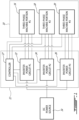
- Figure 1 of the appended drawings schematically shows, in a block diagram, a nine-phase electric machine 10 with its drive circuitry 12 and a DC power source 14.
- the nine phases of the electric machine 10 are divided in three three-phase machine portions 16, 18 and 20 each associated with a respective separate inverter power circuit 22, 24 and 26 which are part of the drive circuitry 12.
- the three inverter power circuits 22-26 are connected to the common DC power source 14.
- the drive circuitry 12 also includes a controller 27, used to control the inverter power circuits 22-26 as will be described hereinbelow.
- the DC power source 14 includes a high voltage battery 28 and a capacitor bank 30. Since the three inverter power circuits 22, 24 and 26 are identical and since the three-phase machine portions 16, 18 and 20 are identical, only one of each will be described hereinbelow, for concision purpose.
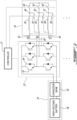
- the schematically illustrated three-phase inverter power circuit 22 conventionally includes six electronically controlled switches 32 and six recovery diodes 34.
- Such a three-phase inverter power circuit 22 is believed well known in the art. Accordingly, its operation to control the current supplied to its associated three-phase machine portion 16 will not be further described herein.
- the electronically controlled switches 32 may be controlled by the controller 27, for example to precisely adjust the phase of the individual three-phase inverter power circuits 22 to 26 with respect to one another.
- other type of three-phase inverter power circuits could be used.
- Each phase A, B and C includes a respective first connection 42, 44 and 46 allowing connection of the various coils to the three-phase inverter power circuit 22.
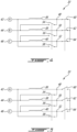
- the machine portion 16 also includes three first contactors 54, 56 and 58 and three second contactors 60, 62 and 64.
- the first contactors 54, 56 and 58 are physically or virtually interconnected so as to be in the same connection state as illustrated by a dashed line and the second contactors 60, 62 and 64 are physically or virtually interconnected so as to be in the same connection state as illustrated by a dashed line. These contactors are controlled by the controller 27.
- the machine portion 16 is placed in a star configuration, by placing the second contactors in their closed position, when the electric machine rotates at relatively low speeds and conventionally requires more torque.
- the voltage required to be supplied to the machine portion 16 by the inverter power circuit 22 is decreased to reach the same maximal rotational speed of the electric machine, which allows the machine to reach a higher rotational speed than the star configuration with the same battery and power semiconductors.
- the controller 27 is so configured as to momentarily stop the inverter power circuit 22 from supplying current to the machine portion 16 when a change of configuration of the contactors is required or desired.
- a single triple-pole contactor could embody the first contactors.
- a single triple-pole contactor could also embody the second contactors.
- one of the second contactors could be replaced by a permanent connection to decrease the overall number of contactor without sacrificing functionality.
- contactors are shown herein as switches allowing the machine portions to be switched between star and delta configurations, other electrically or electronically controlled switches such as, for example, relays, IGBTs or FET could be used.
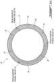
- the machine 10 includes an internal stator 70 and an external rotor 72.
- the internal stator 70 is provided with the three three-phase machine portions 16-20 that each covers about 120 degrees of the circumference of the stator 70.
- the external rotor 72 is provided, in this case, with permanent magnets (not shown).
- each of the three three-phase machine portions 16-20 could be split in two and installed at 180 degrees of each other. This configuration is interesting since it helps keeping the coaxial relationship of the rotor and the stator during operation.
- FIG. 6 of the appended drawings illustrates the maximal torque of a three-phase portion of an electric machine vs. rotational speed of the machine when it is in star or delta configuration.
- This particular electric system has a 300 to 750 Vdc input supply, a diameter of about 552 mm, a length of about 511 mm, a weight of 348 kg, 12 pairs of poles, a maximal speed of 3300 RPM and a maximal torque of 3400 Nm.
- the maximal torque developed by the star configurations is greater than the maximal torque developed by the delta configuration.
- the maximal torque of the delta configuration becomes greater than the maximal torque of the star configuration. It is therefore interesting to switch from star to delta configuration before the 1100 RPM speed is reached.
- each machine portion 16-20 can develop a nominal torque of about 660 Nm when in a delta configuration and a nominal torque of about 1100 Nm when in a star configuration.
- line 102 illustrates the resulting torque from the three machine portions 16-20
- line 104 illustrates the torque from machine portion 16
- line 106 illustrates the torque from machine portion 18
- line 108 illustrates the torque from machine portion 20. From this figure, it is clear that the torque requested by the system user is 1200 Nm (see 102A), which can be obtained using either configuration.
- the machine portions 16-20 are in a star configuration at startup. To maximize efficiency and performance, the requested torque is generally divided equally between the three machine portions 16-20.
- the machine portion 16 is first changed from star to delta.
- the torque 104 of the machine portion 16 is reduced to zero for the short time required for the contactors to switch state.
- the total torque 102 is decreased to 800 Nm (see 102B) since the machine portion 16 is inactive.
- the configuration switch of machine portion 16 it can resume developing torque and the resulting torque is returned to the requested 1200 Nm (see 102C).
- the next step is to change the machine portion 18 from star to delta.
- the torque 106 of the machine portion 18 is reduced to zero for the short time required for the contactors to switch state. During this time the resulting torque 102 is decreased to 800 Nm (see 102D) since the machine portion 18 is inactive.
- Figure 8 of the appended drawings illustrates a first control method to reduce the jolts produced by the configuration changes and thereby improve the driving sensations.
- control method of Figure 8 involves interleaving the configuration changes to avoid the return to the requested torque before the three machine portions have been changed from star to delta. This control method also reduces the overall time needed to complete the change of the configuration of the three machine portions.
- the requested torque is 1200 Nm.
- the torque 104 of the machine portion 16 is decreased to zero for configuration switching, the torque 106 and 108 of the other two machine portions 18 and 20 is increased to 600 Nm each to yield an unchanging resulting torque of 1200 Nm.
- the machine portion 18 and 20 therefore develop a supplemental 200 Nm compensating torque each.
- the configuration change of the machine portion 16 is done, the machine portion 18 is ready for a configuration change.
- the torque of the two active machine portions 16 and 20 is increased to 600 Nm to maintain the 1200 Nm, requested torque.
- the configuration change of the machine portion 20 is done while the torque supplied by the machine portions 16 and 18 is increased to 600 Nm each to prevent any jolt.
- each machine portion 16-20 initially in their star configuration, supplies 500 Nm.
- the torques 106 and 108 of the machine portions 18 and 20 is increased to 750 Nm each which is not a problem since their maximal torque is about 1100 Nm.
- Figure 11 of the appended drawings illustrates the second control method when the configuration of the machine portion has to be changed from delta to star because the requested torque is greater than the torque available in the delta configuration.
- controller determines that a change of configuration is required
- options could also be given to the user of the electric machine to manually change the configuration of one or all of the machine portions.
- manual configuration controls could be available to the user.
- the multiple phase electric machine is not limited in its application to the details of construction and parts illustrated in the accompanying drawings and described hereinabove.
- the multiple phase electric machine is capable of other embodiments and of being practiced in various ways.
- the phraseology or terminology used herein is for the purpose of description and not limitation.
- the multiple phase electric machine has been described hereinabove by way of illustrative embodiments thereof, it can be modified.
Landscapes
- Engineering & Computer Science (AREA)
- Power Engineering (AREA)
- Control Of Ac Motors In General (AREA)
Claims (5)
- Mehrphasige elektrische Maschine (10), umfassend:eine Leistungsquelle (14);einen Stator und einen zum Stator koaxialen Rotor;wobei der Stator Spulen (36, 38, 40) umfasst, die in mindestens zwei Gruppen von jeweils mindestens drei Phasen gruppiert sind, wobei jede der mindestens zwei Gruppen einen Maschinenteil (16, 18, 20) definiert; wobei die Verbindung der mindestens drei Phasen jedes Maschinenteils erste Schalter (54, 56, 58) und zweite Schalter (60, 62, 64) umfasst und eingerichtet ist, zwischen drei Konfigurationen umschaltbar zu sein, einschließlich einer Sternkonfiguration, in der sich die ersten Schalter (54, 56, 58) in ihrer offenen Position und die zweiten Schalter (60, 62, 64) in ihrer geschlossenen Position sind, einer Dreieckskonfiguration, in der die ersten Schalter (54, 56, 58) in ihrer geschlossenen Position sind und die zweiten Schalter (60, 62, 64) in ihrer offenen Position sind, und einer neutralen Konfiguration, in der sowohl die ersten Schalter (54, 56, 58) als auch die zweiten Schalter (60, 62, 64) in ihrer offenen Position sind; undeine Antriebsschaltung umfassend:mindestens zwei Wechselrichter-Leistungsschaltungen (22, 24, 26), die jeweils einem entsprechenden Maschinenteil (16, 18, 20) zugeordnet sind;eine Steuerung (27), die mit den mindestens zwei Wechselrichter-Leistungsschaltungen verbunden ist, um die mindestens zwei Wechselrichter-Leistungsschaltungen unabhängig voneinander zu steuern, und die eingerichtet ist, die Konfiguration der mindestens zwei Maschinenteile nacheinander zwischen der Sternkonfiguration und der Dreieckskonfiguration zu ändern, so dass der andere der mindestens zwei Maschinenteile ein kompensierendes Drehmoment entwickelt.
- Mehrphasige elektrische Maschine (10) nach Anspruch 1, wobei die Steuerung (27) eingerichtet ist, die Konfiguration eines der Maschinenteile (16, 18, 20) zu ändern, indem sie nacheinander die Stromzufuhr zu dem Maschinenteil unterbricht, die Konfiguration des Maschinenteils ändert und die Stromzufuhr zu dem Maschinenteil wieder herstellt.
- Mehrphasige elektrische Maschine (10) nach Anspruch 1, wobei die mindestens zwei Maschinenteile (16, 18, 20) drei Maschinenteile umfassen.
- Mehrphasige elektrische Maschine (10) nach Anspruch 3, wobei die Steuerung (27) eingerichtet ist, die drei Maschinenteile (16, 18, 20) zu steuern, um die Konfiguration eines der Maschinenteile (16, 18, 20) zu ändern, während die beiden anderen Maschinenteile jeweils ein kompensierendes Drehmoment entwickeln.
- Mehrphasige elektrische Maschine (10) nach Anspruch 3, wobei die Steuerung (27) eingerichtet ist, die Konfigurationsänderung der drei Maschinenteile (16, 18, 10) zu überlappen.
Applications Claiming Priority (2)
| Application Number | Priority Date | Filing Date | Title |
|---|---|---|---|
| US201462030226P | 2014-07-29 | 2014-07-29 | |
| PCT/CA2015/050705 WO2016015147A1 (en) | 2014-07-29 | 2015-07-27 | Multiple phase electric machine, drive and control |
Publications (3)
| Publication Number | Publication Date |
|---|---|
| EP3175546A1 EP3175546A1 (de) | 2017-06-07 |
| EP3175546A4 EP3175546A4 (de) | 2018-04-18 |
| EP3175546B1 true EP3175546B1 (de) | 2024-07-10 |
Family
ID=55216527
Family Applications (1)
| Application Number | Title | Priority Date | Filing Date |
|---|---|---|---|
| EP15826485.3A Active EP3175546B1 (de) | 2014-07-29 | 2015-07-27 | Elektrische mehrphasen-maschine, ansteuerung und steuerung |
Country Status (6)
| Country | Link |
|---|---|
| US (1) | US10693408B2 (de) |
| EP (1) | EP3175546B1 (de) |
| KR (1) | KR20170037974A (de) |
| CN (1) | CN107078678B (de) |
| CA (1) | CA2956231C (de) |
| WO (1) | WO2016015147A1 (de) |
Cited By (2)
| Publication number | Priority date | Publication date | Assignee | Title |
|---|---|---|---|---|
| EP4686083A1 (de) * | 2024-07-25 | 2026-01-28 | Texa S.p.A. | System und verfahren zur steuerung eines elektromotors mit axialfluss für ein kraftfahrzeug |
| DE102024133132A1 (de) | 2024-11-13 | 2026-05-13 | Dr. Ing. H.C. F. Porsche Aktiengesellschaft | Elektrische Maschine mit umschaltbarer Verschaltung von Wicklungen |
Families Citing this family (16)
| Publication number | Priority date | Publication date | Assignee | Title |
|---|---|---|---|---|
| CN109863691B (zh) * | 2016-10-31 | 2023-04-04 | 三菱电机株式会社 | 空气调和机以及空气调和机的控制方法 |
| WO2018078839A1 (ja) * | 2016-10-31 | 2018-05-03 | 三菱電機株式会社 | 電動機駆動装置及び空気調和機 |
| DE102016222163B3 (de) * | 2016-11-11 | 2017-07-27 | Continental Automotive Gmbh | Kraftfahrzeug-Bordnetz und Verfahren zum Betrieb eines Kraftfahrzeug-Bordnetzes |
| WO2018163363A1 (ja) * | 2017-03-09 | 2018-09-13 | 三菱電機株式会社 | 電動機の駆動装置および冷凍サイクル適用機器 |
| WO2019026125A1 (ja) * | 2017-07-31 | 2019-02-07 | 三菱電機株式会社 | 電動機駆動装置及び冷凍サイクル適用機器 |
| CN108336933B (zh) * | 2018-01-03 | 2020-06-05 | 广东美芝制冷设备有限公司 | 电机转矩补偿方法、电机转矩补偿系统和永磁同步电机 |
| JP7033958B2 (ja) * | 2018-03-02 | 2022-03-11 | 株式会社日立製作所 | 回転機駆動システム |
| DE102018111732A1 (de) * | 2018-05-16 | 2019-11-21 | Dr. Ing. H.C. F. Porsche Aktiengesellschaft | Elektroantrieb mit aktiver Wicklungsumschaltung und Verfahren zum Betrieb eines Elektroantriebs |
| GB2585855A (en) * | 2019-07-17 | 2021-01-27 | Rolls Royce Plc | Fault-tolerant electrical drive |
| NL2025498B1 (nl) * | 2020-05-04 | 2021-11-18 | Lely Patent Nv | Autonoom voertuig, voersysteem, alsmede werkwijze voor het voeren van dieren |
| IT202000017770A1 (it) * | 2020-07-22 | 2022-01-22 | Eldor Corp Spa | Motore elettrico |
| DE102020126340B4 (de) | 2020-10-08 | 2023-09-21 | Audi Aktiengesellschaft | Wechselrichter für eine Antriebseinrichtung eines elektrisch antreibbaren Kraftfahrzeugs |
| KR102596360B1 (ko) | 2020-12-30 | 2023-10-31 | 주식회사 브이씨텍 | 6상 영구자석 동기 전동기의 고장 대응 운전 장치 |
| US12489347B2 (en) | 2021-03-15 | 2025-12-02 | Cummins Inc. | Electrical machines with segmented inverter components |
| US12348098B2 (en) | 2022-07-22 | 2025-07-01 | Dana Tm4 Inc. | Winding reconfiguration assembly and method for operation of said assembly |
| KR102882240B1 (ko) | 2022-12-30 | 2025-11-06 | 주식회사 브이씨텍 | 다상 모터 고장 전조 증상 검출 방법 및 고장 대응 운전 시스템 |
Family Cites Families (25)
| Publication number | Priority date | Publication date | Assignee | Title |
|---|---|---|---|---|
| US4220440A (en) | 1979-04-06 | 1980-09-02 | Superior Electric Supply Co. | Automatic load seeking control for a pumpjack motor |
| JPH01160393A (ja) * | 1987-12-17 | 1989-06-23 | Fanuc Ltd | 3相誘導電動機の結線切換装置 |
| JPH01164294A (ja) * | 1987-12-19 | 1989-06-28 | Fanuc Ltd | 工作機械のスピンドル駆動制御装置 |
| US5177423A (en) * | 1988-06-14 | 1993-01-05 | Fanuc Ltd. | Winding arrangement in an AC motor |
| JP3037471B2 (ja) * | 1991-07-05 | 2000-04-24 | ファナック株式会社 | 誘導電動機の巻線切換駆動方式 |
| US5614799A (en) * | 1994-07-14 | 1997-03-25 | Mts Systems Corporation | Brushless direct current motor having adjustable motor characteristics |
| JP3399134B2 (ja) | 1994-12-12 | 2003-04-21 | 株式会社明電舎 | 極数切替電動機の運転制御装置 |
| US5818195A (en) * | 1997-06-05 | 1998-10-06 | Mcg, Inc. | Dual state controller for brushless electric motors |
| US6025693A (en) * | 1997-10-20 | 2000-02-15 | Smith; Otto J. M. | Motor starter |
| DE102006021354A1 (de) | 2006-05-08 | 2007-11-15 | Siemens Ag | Elektrische Maschine, insbesondere Synchronmotor, mit redundanten Statorwicklungen |
| EP2149187A1 (de) * | 2007-05-23 | 2010-02-03 | TM4 Inc. | Mehrphasenelektromotor und antrieb |
| JP5547866B2 (ja) * | 2007-06-19 | 2014-07-16 | 株式会社日立産機システム | 誘導電動機駆動装置、電動機駆動システム、及び昇降システム |
| US8125168B2 (en) * | 2007-11-19 | 2012-02-28 | Honeywell International Inc. | Motor having controllable torque |
| US9059658B2 (en) * | 2008-09-02 | 2015-06-16 | International Business Machines Corporation | Increasing tape velocity by dynamic switching |
| GB2462940B8 (en) * | 2009-09-03 | 2012-03-28 | Protean Holdings Corp | Electric motor and electric generator. |
| JP4831503B2 (ja) * | 2009-09-30 | 2011-12-07 | 株式会社デンソー | 多相回転機の制御装置、および、これを用いた電動パワーステアリング装置 |
| US8575880B2 (en) * | 2010-03-17 | 2013-11-05 | Alan Lyndon Grantz | Direct current motor with independently driven and switchable stators |
| WO2013059914A1 (en) | 2011-10-26 | 2013-05-02 | Accelerated Systems Inc. | Apparatus for switching between wye and delta configurations in an electric motor |
| WO2013071937A1 (en) * | 2011-11-16 | 2013-05-23 | Vestas Wind Systems A/S | Protection of a permanent magnet generator |
| WO2013111327A1 (ja) * | 2012-01-27 | 2013-08-01 | 三菱電機株式会社 | モータ制御装置および電動パワーステアリング装置 |
| JP5653386B2 (ja) * | 2012-05-09 | 2015-01-14 | 三菱電機株式会社 | モータ制御装置およびそれを用いた電動パワーステアリング装置 |
| CN202798385U (zh) | 2012-06-12 | 2013-03-13 | 黄宝琛 | 一种多定子多转子电动机及控制电路 |
| GB201313684D0 (en) * | 2013-07-31 | 2013-09-11 | Rolls Royce Plc | A stator winding arrangement for an electrical machine |
| JP5907137B2 (ja) * | 2013-10-02 | 2016-04-20 | 株式会社デンソー | 電力変換装置および電力変換システム |
| US9806642B2 (en) * | 2014-11-06 | 2017-10-31 | Rockwell Automation Technologies, Inc. | Modular multiple single-pole electromagnetic switching system and method |
-
2015
- 2015-07-27 WO PCT/CA2015/050705 patent/WO2016015147A1/en not_active Ceased
- 2015-07-27 US US15/328,709 patent/US10693408B2/en active Active
- 2015-07-27 EP EP15826485.3A patent/EP3175546B1/de active Active
- 2015-07-27 KR KR1020177003113A patent/KR20170037974A/ko not_active Withdrawn
- 2015-07-27 CN CN201580048630.9A patent/CN107078678B/zh active Active
- 2015-07-27 CA CA2956231A patent/CA2956231C/en active Active
Cited By (2)
| Publication number | Priority date | Publication date | Assignee | Title |
|---|---|---|---|---|
| EP4686083A1 (de) * | 2024-07-25 | 2026-01-28 | Texa S.p.A. | System und verfahren zur steuerung eines elektromotors mit axialfluss für ein kraftfahrzeug |
| DE102024133132A1 (de) | 2024-11-13 | 2026-05-13 | Dr. Ing. H.C. F. Porsche Aktiengesellschaft | Elektrische Maschine mit umschaltbarer Verschaltung von Wicklungen |
Also Published As
| Publication number | Publication date |
|---|---|
| KR20170037974A (ko) | 2017-04-05 |
| CN107078678B (zh) | 2020-02-07 |
| EP3175546A4 (de) | 2018-04-18 |
| EP3175546A1 (de) | 2017-06-07 |
| CN107078678A (zh) | 2017-08-18 |
| CA2956231C (en) | 2023-02-14 |
| CA2956231A1 (en) | 2016-02-04 |
| US20170229993A1 (en) | 2017-08-10 |
| WO2016015147A1 (en) | 2016-02-04 |
| US10693408B2 (en) | 2020-06-23 |
Similar Documents
| Publication | Publication Date | Title |
|---|---|---|
| CA2956231C (en) | Multiple phase electric machine, drive and control | |
| US10411573B2 (en) | Permanent-magnet synchronous machine and motor vehicle system | |
| KR101787135B1 (ko) | 전기 기계 | |
| CN103339835B (zh) | 定子齿、定子、旋转电机、及旋转电机的控制方法 | |
| US7122994B2 (en) | Control apparatus for a starter/generator system | |
| US9677531B2 (en) | Multiphase induction motor with configurable windings | |
| JP2009303298A (ja) | 交流モータ装置 | |
| US20110181222A1 (en) | Motor control system and method | |
| JP4691897B2 (ja) | 電動機駆動システム | |
| KR20160063283A (ko) | 브러시리스 직류 전기 모터 및 전동 파워 스티어링 시스템 | |
| US10819176B2 (en) | Electric motor | |
| US20170104398A1 (en) | Hybrid dual-rotor structure | |
| US20080309262A1 (en) | Multiple Phase Electric Motor and Drive | |
| KR101237123B1 (ko) | 단일 외부 전원 공급형 가변속 유도 전동기 및 그 제어 방법 | |
| WO2018030143A1 (ja) | 駆動装置及び電動モータ駆動装置 | |
| WO2017213073A1 (ja) | 動力出力装置 | |
| EP1560318A1 (de) | Anlassgenerierungssystem und anlassgenerator | |
| JP6013073B2 (ja) | 電動機駆動装置及びその運転方法 | |
| Drozdowski | Speed control of multiphase cage induction motors incorporating supply sequence | |
| JP2015227079A (ja) | 駆動システム | |
| RU2272351C1 (ru) | Синхронный двигатель | |
| JP2007236179A (ja) | モータ装置 | |
| WO2016042335A1 (en) | Energy storage system and control method thereof | |
| CN107078584B (zh) | 九相感应电动机起动器/交流发电机 | |
| US20220302864A1 (en) | Switched reluctance machine having a switch for changing the number of turns |
Legal Events
| Date | Code | Title | Description |
|---|---|---|---|
| STAA | Information on the status of an ep patent application or granted ep patent |
Free format text: STATUS: THE INTERNATIONAL PUBLICATION HAS BEEN MADE |
|
| 17P | Request for examination filed |
Effective date: 20170213 |
|
| AK | Designated contracting states |
Kind code of ref document: A1 Designated state(s): AL AT BE BG CH CY CZ DE DK EE ES FI FR GB GR HR HU IE IS IT LI LT LU LV MC MK MT NL NO PL PT RO RS SE SI SK SM TR |
|
| AX | Request for extension of the european patent |
Extension state: BA ME |
|
| PUAI | Public reference made under article 153(3) epc to a published international application that has entered the european phase |
Free format text: ORIGINAL CODE: 0009012 |
|
| STAA | Information on the status of an ep patent application or granted ep patent |
Free format text: STATUS: REQUEST FOR EXAMINATION WAS MADE |
|
| DAV | Request for validation of the european patent (deleted) | ||
| DAX | Request for extension of the european patent (deleted) | ||
| A4 | Supplementary search report drawn up and despatched |
Effective date: 20180316 |
|
| RIC1 | Information provided on ipc code assigned before grant |
Ipc: H02P 27/00 20060101ALI20180312BHEP Ipc: H02P 25/18 20060101AFI20180312BHEP Ipc: H02P 25/02 20160101ALI20180312BHEP |
|
| RAP1 | Party data changed (applicant data changed or rights of an application transferred) |
Owner name: DANA TM4 INC. |
|
| STAA | Information on the status of an ep patent application or granted ep patent |
Free format text: STATUS: EXAMINATION IS IN PROGRESS |
|
| 17Q | First examination report despatched |
Effective date: 20210201 |
|
| GRAP | Despatch of communication of intention to grant a patent |
Free format text: ORIGINAL CODE: EPIDOSNIGR1 |
|
| STAA | Information on the status of an ep patent application or granted ep patent |
Free format text: STATUS: GRANT OF PATENT IS INTENDED |
|
| INTG | Intention to grant announced |
Effective date: 20240223 |
|
| P01 | Opt-out of the competence of the unified patent court (upc) registered |
Effective date: 20240301 |
|
| GRAS | Grant fee paid |
Free format text: ORIGINAL CODE: EPIDOSNIGR3 |
|
| GRAA | (expected) grant |
Free format text: ORIGINAL CODE: 0009210 |
|
| STAA | Information on the status of an ep patent application or granted ep patent |
Free format text: STATUS: THE PATENT HAS BEEN GRANTED |
|
| AK | Designated contracting states |
Kind code of ref document: B1 Designated state(s): AL AT BE BG CH CY CZ DE DK EE ES FI FR GB GR HR HU IE IS IT LI LT LU LV MC MK MT NL NO PL PT RO RS SE SI SK SM TR |
|
| REG | Reference to a national code |
Ref country code: CH Ref legal event code: EP |
|
| REG | Reference to a national code |
Ref country code: DE Ref legal event code: R096 Ref document number: 602015089192 Country of ref document: DE |
|
| REG | Reference to a national code |
Ref country code: LT Ref legal event code: MG9D |
|
| REG | Reference to a national code |
Ref country code: NL Ref legal event code: MP Effective date: 20240710 |
|
| PG25 | Lapsed in a contracting state [announced via postgrant information from national office to epo] |
Ref country code: PT Free format text: LAPSE BECAUSE OF FAILURE TO SUBMIT A TRANSLATION OF THE DESCRIPTION OR TO PAY THE FEE WITHIN THE PRESCRIBED TIME-LIMIT Effective date: 20241111 |
|
| REG | Reference to a national code |
Ref country code: AT Ref legal event code: MK05 Ref document number: 1702928 Country of ref document: AT Kind code of ref document: T Effective date: 20240710 |
|
| PG25 | Lapsed in a contracting state [announced via postgrant information from national office to epo] |
Ref country code: NL Free format text: LAPSE BECAUSE OF FAILURE TO SUBMIT A TRANSLATION OF THE DESCRIPTION OR TO PAY THE FEE WITHIN THE PRESCRIBED TIME-LIMIT Effective date: 20240710 |
|
| PG25 | Lapsed in a contracting state [announced via postgrant information from national office to epo] |
Ref country code: PT Free format text: LAPSE BECAUSE OF FAILURE TO SUBMIT A TRANSLATION OF THE DESCRIPTION OR TO PAY THE FEE WITHIN THE PRESCRIBED TIME-LIMIT Effective date: 20241111 Ref country code: NL Free format text: LAPSE BECAUSE OF FAILURE TO SUBMIT A TRANSLATION OF THE DESCRIPTION OR TO PAY THE FEE WITHIN THE PRESCRIBED TIME-LIMIT Effective date: 20240710 |
|
| PG25 | Lapsed in a contracting state [announced via postgrant information from national office to epo] |
Ref country code: NO Free format text: LAPSE BECAUSE OF FAILURE TO SUBMIT A TRANSLATION OF THE DESCRIPTION OR TO PAY THE FEE WITHIN THE PRESCRIBED TIME-LIMIT Effective date: 20241010 |
|
| PG25 | Lapsed in a contracting state [announced via postgrant information from national office to epo] |
Ref country code: PL Free format text: LAPSE BECAUSE OF FAILURE TO SUBMIT A TRANSLATION OF THE DESCRIPTION OR TO PAY THE FEE WITHIN THE PRESCRIBED TIME-LIMIT Effective date: 20240710 Ref country code: FI Free format text: LAPSE BECAUSE OF FAILURE TO SUBMIT A TRANSLATION OF THE DESCRIPTION OR TO PAY THE FEE WITHIN THE PRESCRIBED TIME-LIMIT Effective date: 20240710 Ref country code: GR Free format text: LAPSE BECAUSE OF FAILURE TO SUBMIT A TRANSLATION OF THE DESCRIPTION OR TO PAY THE FEE WITHIN THE PRESCRIBED TIME-LIMIT Effective date: 20241011 |
|
| PG25 | Lapsed in a contracting state [announced via postgrant information from national office to epo] |
Ref country code: BG Free format text: LAPSE BECAUSE OF FAILURE TO SUBMIT A TRANSLATION OF THE DESCRIPTION OR TO PAY THE FEE WITHIN THE PRESCRIBED TIME-LIMIT Effective date: 20240710 |
|
| PG25 | Lapsed in a contracting state [announced via postgrant information from national office to epo] |
Ref country code: LV Free format text: LAPSE BECAUSE OF FAILURE TO SUBMIT A TRANSLATION OF THE DESCRIPTION OR TO PAY THE FEE WITHIN THE PRESCRIBED TIME-LIMIT Effective date: 20240710 |
|
| PG25 | Lapsed in a contracting state [announced via postgrant information from national office to epo] |
Ref country code: IS Free format text: LAPSE BECAUSE OF FAILURE TO SUBMIT A TRANSLATION OF THE DESCRIPTION OR TO PAY THE FEE WITHIN THE PRESCRIBED TIME-LIMIT Effective date: 20241110 Ref country code: AT Free format text: LAPSE BECAUSE OF FAILURE TO SUBMIT A TRANSLATION OF THE DESCRIPTION OR TO PAY THE FEE WITHIN THE PRESCRIBED TIME-LIMIT Effective date: 20240710 |
|
| PG25 | Lapsed in a contracting state [announced via postgrant information from national office to epo] |
Ref country code: HR Free format text: LAPSE BECAUSE OF FAILURE TO SUBMIT A TRANSLATION OF THE DESCRIPTION OR TO PAY THE FEE WITHIN THE PRESCRIBED TIME-LIMIT Effective date: 20240710 |
|
| PG25 | Lapsed in a contracting state [announced via postgrant information from national office to epo] |
Ref country code: ES Free format text: LAPSE BECAUSE OF FAILURE TO SUBMIT A TRANSLATION OF THE DESCRIPTION OR TO PAY THE FEE WITHIN THE PRESCRIBED TIME-LIMIT Effective date: 20240710 Ref country code: RS Free format text: LAPSE BECAUSE OF FAILURE TO SUBMIT A TRANSLATION OF THE DESCRIPTION OR TO PAY THE FEE WITHIN THE PRESCRIBED TIME-LIMIT Effective date: 20241010 |
|
| PG25 | Lapsed in a contracting state [announced via postgrant information from national office to epo] |
Ref country code: RS Free format text: LAPSE BECAUSE OF FAILURE TO SUBMIT A TRANSLATION OF THE DESCRIPTION OR TO PAY THE FEE WITHIN THE PRESCRIBED TIME-LIMIT Effective date: 20241010 Ref country code: PL Free format text: LAPSE BECAUSE OF FAILURE TO SUBMIT A TRANSLATION OF THE DESCRIPTION OR TO PAY THE FEE WITHIN THE PRESCRIBED TIME-LIMIT Effective date: 20240710 Ref country code: NO Free format text: LAPSE BECAUSE OF FAILURE TO SUBMIT A TRANSLATION OF THE DESCRIPTION OR TO PAY THE FEE WITHIN THE PRESCRIBED TIME-LIMIT Effective date: 20241010 Ref country code: LV Free format text: LAPSE BECAUSE OF FAILURE TO SUBMIT A TRANSLATION OF THE DESCRIPTION OR TO PAY THE FEE WITHIN THE PRESCRIBED TIME-LIMIT Effective date: 20240710 Ref country code: IS Free format text: LAPSE BECAUSE OF FAILURE TO SUBMIT A TRANSLATION OF THE DESCRIPTION OR TO PAY THE FEE WITHIN THE PRESCRIBED TIME-LIMIT Effective date: 20241110 Ref country code: HR Free format text: LAPSE BECAUSE OF FAILURE TO SUBMIT A TRANSLATION OF THE DESCRIPTION OR TO PAY THE FEE WITHIN THE PRESCRIBED TIME-LIMIT Effective date: 20240710 Ref country code: GR Free format text: LAPSE BECAUSE OF FAILURE TO SUBMIT A TRANSLATION OF THE DESCRIPTION OR TO PAY THE FEE WITHIN THE PRESCRIBED TIME-LIMIT Effective date: 20241011 Ref country code: FI Free format text: LAPSE BECAUSE OF FAILURE TO SUBMIT A TRANSLATION OF THE DESCRIPTION OR TO PAY THE FEE WITHIN THE PRESCRIBED TIME-LIMIT Effective date: 20240710 Ref country code: ES Free format text: LAPSE BECAUSE OF FAILURE TO SUBMIT A TRANSLATION OF THE DESCRIPTION OR TO PAY THE FEE WITHIN THE PRESCRIBED TIME-LIMIT Effective date: 20240710 Ref country code: BG Free format text: LAPSE BECAUSE OF FAILURE TO SUBMIT A TRANSLATION OF THE DESCRIPTION OR TO PAY THE FEE WITHIN THE PRESCRIBED TIME-LIMIT Effective date: 20240710 Ref country code: AT Free format text: LAPSE BECAUSE OF FAILURE TO SUBMIT A TRANSLATION OF THE DESCRIPTION OR TO PAY THE FEE WITHIN THE PRESCRIBED TIME-LIMIT Effective date: 20240710 |
|
| REG | Reference to a national code |
Ref country code: CH Ref legal event code: PL |
|
| PG25 | Lapsed in a contracting state [announced via postgrant information from national office to epo] |
Ref country code: LU Free format text: LAPSE BECAUSE OF NON-PAYMENT OF DUE FEES Effective date: 20240727 |
|
| PG25 | Lapsed in a contracting state [announced via postgrant information from national office to epo] |
Ref country code: LU Free format text: LAPSE BECAUSE OF NON-PAYMENT OF DUE FEES Effective date: 20240727 |
|
| REG | Reference to a national code |
Ref country code: DE Ref legal event code: R097 Ref document number: 602015089192 Country of ref document: DE |
|
| PG25 | Lapsed in a contracting state [announced via postgrant information from national office to epo] |
Ref country code: DK Free format text: LAPSE BECAUSE OF FAILURE TO SUBMIT A TRANSLATION OF THE DESCRIPTION OR TO PAY THE FEE WITHIN THE PRESCRIBED TIME-LIMIT Effective date: 20240710 Ref country code: SM Free format text: LAPSE BECAUSE OF FAILURE TO SUBMIT A TRANSLATION OF THE DESCRIPTION OR TO PAY THE FEE WITHIN THE PRESCRIBED TIME-LIMIT Effective date: 20240710 Ref country code: RO Free format text: LAPSE BECAUSE OF FAILURE TO SUBMIT A TRANSLATION OF THE DESCRIPTION OR TO PAY THE FEE WITHIN THE PRESCRIBED TIME-LIMIT Effective date: 20240710 |
|
| PG25 | Lapsed in a contracting state [announced via postgrant information from national office to epo] |
Ref country code: MC Free format text: LAPSE BECAUSE OF FAILURE TO SUBMIT A TRANSLATION OF THE DESCRIPTION OR TO PAY THE FEE WITHIN THE PRESCRIBED TIME-LIMIT Effective date: 20240710 Ref country code: BE Free format text: LAPSE BECAUSE OF NON-PAYMENT OF DUE FEES Effective date: 20240731 Ref country code: CH Free format text: LAPSE BECAUSE OF NON-PAYMENT OF DUE FEES Effective date: 20240731 Ref country code: EE Free format text: LAPSE BECAUSE OF FAILURE TO SUBMIT A TRANSLATION OF THE DESCRIPTION OR TO PAY THE FEE WITHIN THE PRESCRIBED TIME-LIMIT Effective date: 20240710 |
|
| PG25 | Lapsed in a contracting state [announced via postgrant information from national office to epo] |
Ref country code: CZ Free format text: LAPSE BECAUSE OF FAILURE TO SUBMIT A TRANSLATION OF THE DESCRIPTION OR TO PAY THE FEE WITHIN THE PRESCRIBED TIME-LIMIT Effective date: 20240710 |
|
| PG25 | Lapsed in a contracting state [announced via postgrant information from national office to epo] |
Ref country code: IT Free format text: LAPSE BECAUSE OF FAILURE TO SUBMIT A TRANSLATION OF THE DESCRIPTION OR TO PAY THE FEE WITHIN THE PRESCRIBED TIME-LIMIT Effective date: 20240710 Ref country code: SK Free format text: LAPSE BECAUSE OF FAILURE TO SUBMIT A TRANSLATION OF THE DESCRIPTION OR TO PAY THE FEE WITHIN THE PRESCRIBED TIME-LIMIT Effective date: 20240710 |
|
| PLBE | No opposition filed within time limit |
Free format text: ORIGINAL CODE: 0009261 |
|
| STAA | Information on the status of an ep patent application or granted ep patent |
Free format text: STATUS: NO OPPOSITION FILED WITHIN TIME LIMIT |
|
| REG | Reference to a national code |
Ref country code: BE Ref legal event code: MM Effective date: 20240731 |
|
| 26N | No opposition filed |
Effective date: 20250411 |
|
| GBPC | Gb: european patent ceased through non-payment of renewal fee |
Effective date: 20241010 |
|
| PG25 | Lapsed in a contracting state [announced via postgrant information from national office to epo] |
Ref country code: GB Free format text: LAPSE BECAUSE OF NON-PAYMENT OF DUE FEES Effective date: 20241010 |
|
| PG25 | Lapsed in a contracting state [announced via postgrant information from national office to epo] |
Ref country code: FR Free format text: LAPSE BECAUSE OF NON-PAYMENT OF DUE FEES Effective date: 20240910 |
|
| PG25 | Lapsed in a contracting state [announced via postgrant information from national office to epo] |
Ref country code: IE Free format text: LAPSE BECAUSE OF NON-PAYMENT OF DUE FEES Effective date: 20240727 |
|
| PG25 | Lapsed in a contracting state [announced via postgrant information from national office to epo] |
Ref country code: SE Free format text: LAPSE BECAUSE OF FAILURE TO SUBMIT A TRANSLATION OF THE DESCRIPTION OR TO PAY THE FEE WITHIN THE PRESCRIBED TIME-LIMIT Effective date: 20240710 |
|
| PGFP | Annual fee paid to national office [announced via postgrant information from national office to epo] |
Ref country code: DE Payment date: 20250620 Year of fee payment: 11 |
|
| PG25 | Lapsed in a contracting state [announced via postgrant information from national office to epo] |
Ref country code: CY Free format text: LAPSE BECAUSE OF FAILURE TO SUBMIT A TRANSLATION OF THE DESCRIPTION OR TO PAY THE FEE WITHIN THE PRESCRIBED TIME-LIMIT; INVALID AB INITIO Effective date: 20150727 |
|
| PG25 | Lapsed in a contracting state [announced via postgrant information from national office to epo] |
Ref country code: HU Free format text: LAPSE BECAUSE OF FAILURE TO SUBMIT A TRANSLATION OF THE DESCRIPTION OR TO PAY THE FEE WITHIN THE PRESCRIBED TIME-LIMIT; INVALID AB INITIO Effective date: 20150727 |