EP3175119B1 - Strömungsführendes bauteil - Google Patents
Strömungsführendes bauteil Download PDFInfo
- Publication number
- EP3175119B1 EP3175119B1 EP15744185.8A EP15744185A EP3175119B1 EP 3175119 B1 EP3175119 B1 EP 3175119B1 EP 15744185 A EP15744185 A EP 15744185A EP 3175119 B1 EP3175119 B1 EP 3175119B1
- Authority
- EP
- European Patent Office
- Prior art keywords
- component
- flow
- point
- angle
- component according
- Prior art date
- Legal status (The legal status is an assumption and is not a legal conclusion. Google has not performed a legal analysis and makes no representation as to the accuracy of the status listed.)
- Active
Links
Images

Classifications
-
- F—MECHANICAL ENGINEERING; LIGHTING; HEATING; WEAPONS; BLASTING
- F04—POSITIVE - DISPLACEMENT MACHINES FOR LIQUIDS; PUMPS FOR LIQUIDS OR ELASTIC FLUIDS
- F04D—NON-POSITIVE-DISPLACEMENT PUMPS
- F04D29/00—Details, component parts, or accessories
- F04D29/02—Selection of particular materials
- F04D29/023—Selection of particular materials especially adapted for elastic fluid pumps
-
- F—MECHANICAL ENGINEERING; LIGHTING; HEATING; WEAPONS; BLASTING
- F04—POSITIVE - DISPLACEMENT MACHINES FOR LIQUIDS; PUMPS FOR LIQUIDS OR ELASTIC FLUIDS
- F04D—NON-POSITIVE-DISPLACEMENT PUMPS
- F04D29/00—Details, component parts, or accessories
- F04D29/18—Rotors
- F04D29/22—Rotors specially for centrifugal pumps
-
- F—MECHANICAL ENGINEERING; LIGHTING; HEATING; WEAPONS; BLASTING
- F04—POSITIVE - DISPLACEMENT MACHINES FOR LIQUIDS; PUMPS FOR LIQUIDS OR ELASTIC FLUIDS
- F04D—NON-POSITIVE-DISPLACEMENT PUMPS
- F04D29/00—Details, component parts, or accessories
- F04D29/02—Selection of particular materials
- F04D29/026—Selection of particular materials especially adapted for liquid pumps
-
- F—MECHANICAL ENGINEERING; LIGHTING; HEATING; WEAPONS; BLASTING
- F04—POSITIVE - DISPLACEMENT MACHINES FOR LIQUIDS; PUMPS FOR LIQUIDS OR ELASTIC FLUIDS
- F04D—NON-POSITIVE-DISPLACEMENT PUMPS
- F04D29/00—Details, component parts, or accessories
- F04D29/18—Rotors
- F04D29/22—Rotors specially for centrifugal pumps
- F04D29/2205—Conventional flow pattern
- F04D29/2222—Construction and assembly
- F04D29/2227—Construction and assembly for special materials
-
- F—MECHANICAL ENGINEERING; LIGHTING; HEATING; WEAPONS; BLASTING
- F04—POSITIVE - DISPLACEMENT MACHINES FOR LIQUIDS; PUMPS FOR LIQUIDS OR ELASTIC FLUIDS
- F04D—NON-POSITIVE-DISPLACEMENT PUMPS
- F04D29/00—Details, component parts, or accessories
- F04D29/18—Rotors
- F04D29/22—Rotors specially for centrifugal pumps
- F04D29/24—Vanes
- F04D29/242—Geometry, shape
- F04D29/245—Geometry, shape for special effects
-
- F—MECHANICAL ENGINEERING; LIGHTING; HEATING; WEAPONS; BLASTING
- F04—POSITIVE - DISPLACEMENT MACHINES FOR LIQUIDS; PUMPS FOR LIQUIDS OR ELASTIC FLUIDS
- F04D—NON-POSITIVE-DISPLACEMENT PUMPS
- F04D29/00—Details, component parts, or accessories
- F04D29/26—Rotors specially for elastic fluids
- F04D29/28—Rotors specially for elastic fluids for centrifugal or helico-centrifugal pumps for radial-flow or helico-centrifugal pumps
-
- F—MECHANICAL ENGINEERING; LIGHTING; HEATING; WEAPONS; BLASTING
- F04—POSITIVE - DISPLACEMENT MACHINES FOR LIQUIDS; PUMPS FOR LIQUIDS OR ELASTIC FLUIDS
- F04D—NON-POSITIVE-DISPLACEMENT PUMPS
- F04D29/00—Details, component parts, or accessories
- F04D29/26—Rotors specially for elastic fluids
- F04D29/32—Rotors specially for elastic fluids for axial flow pumps
- F04D29/34—Blade mountings
-
- F—MECHANICAL ENGINEERING; LIGHTING; HEATING; WEAPONS; BLASTING
- F04—POSITIVE - DISPLACEMENT MACHINES FOR LIQUIDS; PUMPS FOR LIQUIDS OR ELASTIC FLUIDS
- F04D—NON-POSITIVE-DISPLACEMENT PUMPS
- F04D29/00—Details, component parts, or accessories
- F04D29/26—Rotors specially for elastic fluids
- F04D29/32—Rotors specially for elastic fluids for axial flow pumps
- F04D29/321—Rotors specially for elastic fluids for axial flow pumps for axial flow compressors
- F04D29/322—Blade mountings
-
- F—MECHANICAL ENGINEERING; LIGHTING; HEATING; WEAPONS; BLASTING
- F05—INDEXING SCHEMES RELATING TO ENGINES OR PUMPS IN VARIOUS SUBCLASSES OF CLASSES F01-F04
- F05D—INDEXING SCHEME FOR ASPECTS RELATING TO NON-POSITIVE-DISPLACEMENT MACHINES OR ENGINES, GAS-TURBINES OR JET-PROPULSION PLANTS
- F05D2230/00—Manufacture
- F05D2230/20—Manufacture essentially without removing material
- F05D2230/22—Manufacture essentially without removing material by sintering
-
- F—MECHANICAL ENGINEERING; LIGHTING; HEATING; WEAPONS; BLASTING
- F05—INDEXING SCHEMES RELATING TO ENGINES OR PUMPS IN VARIOUS SUBCLASSES OF CLASSES F01-F04
- F05D—INDEXING SCHEME FOR ASPECTS RELATING TO NON-POSITIVE-DISPLACEMENT MACHINES OR ENGINES, GAS-TURBINES OR JET-PROPULSION PLANTS
- F05D2230/00—Manufacture
- F05D2230/20—Manufacture essentially without removing material
- F05D2230/23—Manufacture essentially without removing material by permanently joining parts together
- F05D2230/232—Manufacture essentially without removing material by permanently joining parts together by welding
- F05D2230/233—Electron beam welding
-
- F—MECHANICAL ENGINEERING; LIGHTING; HEATING; WEAPONS; BLASTING
- F05—INDEXING SCHEMES RELATING TO ENGINES OR PUMPS IN VARIOUS SUBCLASSES OF CLASSES F01-F04
- F05D—INDEXING SCHEME FOR ASPECTS RELATING TO NON-POSITIVE-DISPLACEMENT MACHINES OR ENGINES, GAS-TURBINES OR JET-PROPULSION PLANTS
- F05D2230/00—Manufacture
- F05D2230/20—Manufacture essentially without removing material
- F05D2230/23—Manufacture essentially without removing material by permanently joining parts together
- F05D2230/232—Manufacture essentially without removing material by permanently joining parts together by welding
- F05D2230/234—Laser welding
-
- F—MECHANICAL ENGINEERING; LIGHTING; HEATING; WEAPONS; BLASTING
- F05—INDEXING SCHEMES RELATING TO ENGINES OR PUMPS IN VARIOUS SUBCLASSES OF CLASSES F01-F04
- F05D—INDEXING SCHEME FOR ASPECTS RELATING TO NON-POSITIVE-DISPLACEMENT MACHINES OR ENGINES, GAS-TURBINES OR JET-PROPULSION PLANTS
- F05D2230/00—Manufacture
- F05D2230/30—Manufacture with deposition of material
- F05D2230/31—Layer deposition
-
- F—MECHANICAL ENGINEERING; LIGHTING; HEATING; WEAPONS; BLASTING
- F05—INDEXING SCHEMES RELATING TO ENGINES OR PUMPS IN VARIOUS SUBCLASSES OF CLASSES F01-F04
- F05D—INDEXING SCHEME FOR ASPECTS RELATING TO NON-POSITIVE-DISPLACEMENT MACHINES OR ENGINES, GAS-TURBINES OR JET-PROPULSION PLANTS
- F05D2300/00—Materials; Properties thereof
- F05D2300/10—Metals, alloys or intermetallic compounds
- F05D2300/11—Iron
Definitions
- the present invention relates to the geometric design of a flow-guiding component with special consideration of the mechanical load, wherein the component transitions between individual areas are affected by notches, the load collective of the notches can be calculated, and the production of such a component.
- Flow-guiding components are known in various embodiments. Depending on the conditions of use, ie working pressure, pumped liquid, medium temperature or similar, the component is made of special materials. The static structure of the housing is also heavily dependent on the application.
- the EP 1 785 590 A1 shows the design and manufacture of an impeller of a pump or turbine, with particular attention is paid to the design of the notches.
- the impeller is welded in several layers, whereby voltages are directly suppressed. The procedure requires access to the notches during manufacture with appropriate tools.
- the object of the invention is to find and apply a geometric design for the mechanical load at the transition points of a flow-guiding component, especially in the region of the notches, which is simple and inexpensive to produce.
- the flow-leading part which may be an impeller for a centrifugal pump, for example, can be constructed free of classical specifications. Limitations of foundry technology and / or joining methods need not be taken into account in the design of the component, since only the mechanical and hydraulic properties are important. Such an exemption from traditional design principles allows a completely new design of the impeller.
- This simple construction method makes it very easy to determine a geometry that takes into account the mechanical load in the component, depending on the direction. Attacking forces are analyzed under the influence of the conveyed medium and the intended working conditions, whereby minimum and maximum values are determined. According to these values, the demand of the impeller for mechanical stability is determined. The calculation method specifies the geometric design and thus also the material usage and the workpiece machining.
- the flow-guiding component is produced by a generative method, in which, in particular, metal powders are joined to form a component by a jet melting method, such as, for example, laser or electron beam melts.
- a jet melting method such as, for example, laser or electron beam melts.
- At least one notch is arranged in the interior of the component in the flow-guiding component, in particular in a cavity and / or an undercut.
- the flow-guiding component is a pump component, in particular a centrifugal pump.
- a pump component in particular a centrifugal pump.
- the geometric design in particular in wheels and / or guide wheels of centrifugal pumps. These parts are particularly heavily mechanically stressed. The transitions between a guide / impeller blade and a cover plate are sometimes very difficult to access.
- the surfaces of the individual impeller blades can also be designed freely, so that the boundary layer between the impeller and the fluid can be influenced.
- inducers it is also possible for inducers to make components hollow, whereby considerable material savings are possible.
- the component must then its mechanical stability by the appropriate design of the struts obtained within the cavities, as well as the transitions between mechanically stabilizing areas according to the above design rule.
- the component is made of an iron-based material.
- the iron-based material is an austenitic or martensitic or ferritic or duplex material. This allows the production of corrosion-resistant components.
- the preparation of the powders required for the high-energy jet methods mentioned is likewise inexpensive and simple. This becomes even clearer when the iron base material is advantageously a gray or nodular cast iron material.
- drawing 1 shows the method according to the invention for constructing the notch between two regions of a flow-guiding component.
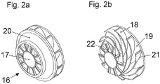
- Drawing 2 explains the application of the method according to the invention for the construction of a centrifugal pump impeller, as well as the advantages of a generic production.
- FIG. 1 shows an arbitrary point at which the contour of a component changes discontinuously from a first region 1 into a second region 2, wherein the two regions enclose an angle 3.
- Significant stresses develop at this point of discontinuity, which can be strongly influenced by a suitably constructed geometric course.
- a predetermined breaking point one would like to use the stresses to allow the component to be selectively crushed at the point of discontinuity during a threshold load.
- the opposite is desirable and the point of discontinuity should be sufficiently resilient against the applied forces.
- a so-called engineering notch is provided here, which forms the sharp angle by a rounding with a selected radius.
- an angle bisector 4 is constructed by the angle 3.
- a point 5 is selected on this bisector 4.
- This point 5 are perpendicular to the areas 1 and 2, the lines 6 and 7 laid. To these straight lines 6 and 7 will be at point 5 at an angle of 8 to 45 ° straight lines intersect the areas 1 and 2, wherein in the area 2 of the intersection 11 is set.
- the proposed construction is based on a non-symmetrical loading of a component. If the component were loaded symmetrically, for example by an alternating left / right rotation, then the construction could be symmetrically supplemented in the direction of the first region 1 in an analogous manner.
- FIG. 2 shows an exemplary application for the construction and manufacturing method according to the invention.
- an impeller 16 is shown, as used for example in a centrifugal pump.
- the impeller 16 has a hub portion 17 and a cover plate 20. More details are the FIG. 2b refer to.
- Such an impeller with the two shrouds 20 and 19 is referred to as a closed impeller.
- the impeller blades 18 have, both in the region of the impeller hub 17 and in the region of the cover disks 19 and 20, transitions 21 and 22, respectively, which correspond to those in FIG FIG. 1 correspond described.
- the transition 21 can be described such that the surface of the cover disk 19 represents the first region 1 and the impeller 16 the second region 2.
- the forces occurring at the point of discontinuity between the two areas 1 and 2 can be determined from the parameters of the impeller, the fluid of the pump and the application. Based on these forces, the point 5 is set in the notch to be constructed. With this point, the notch is constructed. If the impeller 16 is made, for example, in a 3d printing process, the contours of the transitions 21 and 22 at each point of the impeller can be determined with the accuracy of the resolution of the printing process be prepared without any reworking will be necessary. This particularly advantageous contour, which would not be produced with a corresponding shape fidelity with conventional machining methods, can even be constructed in places that would not be attainable with tools for post-processing, which is apparent from the FIG. 2 initially not directly derivable.
- the proposed design and manufacturing principle combines the effect of a generic 3d printing production process, which inherently works with discrete elements in which individual voxels or layers are joined to a workpiece with a method of optimizing a non-continuous surface geometry. As a result, it is possible to dispense with further post-processing of the workpiece, during which the individual layers of production must be "smoothed" to form a continuous body.
Landscapes
- Engineering & Computer Science (AREA)
- Mechanical Engineering (AREA)
- General Engineering & Computer Science (AREA)
- Physics & Mathematics (AREA)
- Geometry (AREA)
- Structures Of Non-Positive Displacement Pumps (AREA)
- Measuring Volume Flow (AREA)
- Non-Insulated Conductors (AREA)
- Cell Electrode Carriers And Collectors (AREA)
Description
- Die vorliegende Erfindung betrifft die geometrische Ausgestaltung eines strömungsführenden Bauteils unter besonderer Berücksichtigung der mechanischen Belastung, wobei bei dem Bauteil Übergänge zwischen einzelnen Bereichen durch Kerben behaftet sind, wobei das Lastkollektiv der Kerben rechnerisch ermittelbar ist, sowie die Herstellung eines solchen Bauteils.
- Strömungsführende Bauteile sind in verschiedenen Ausführungsformen bekannt. Je nach Einsatzbedingungen, also Arbeitsdruck, Fördermedium, Medientemperatur oder ähnlichem, ist das Bauteil aus speziellen Materialien gefertigt. Der statische Aufbau des Gehäuses ist ebenfalls stark vom Einsatzgebiet abhängig.
- Besonders beanspruchte Bereiche und vor allem an den Übergängen zwischen verschiedenen Bereichen können besondere mechanische Spannungen aufgebaut werden, die zu verkürzten Standzeiten führen. Durch eine vorteilhafte Ausgestaltung der Kerbe lassen sich Spannungen stark reduzieren, dies erfordert jedoch eine Bearbeitung des Übergangsbereiches mit Werkzeugen.
- Die
EP 1 785 590 A1 zeigt die Ausgestaltung und Herstellung eines Laufrades einer Pumpe oder Turbine, wobei besonders Augenmerk auf der Gestaltung der Kerben liegt. Das Laufrad wird in mehreren Lagen verschweißt, wobei Spannungen direkt unterbunden werden. Die Vorgehensweise erfordert bei der Herstellung einen Zugang mit entsprechenden Werkzeugen zu den Kerben. - Sowohl Gusstechnik als auch Fügetechnik gelangen schnell an Grenzen für strömungsführende Bauteile, da teilweise die Kerben außen nur schwer und/oder gar nicht direkt zugänglich sind. Dies führt zu erheblichen Einschränkungen bei der Ausgestaltung der Geometrie des Bauteils.
-
DE 10 2012 106810 A1 ,JP 2009 185733 A US 2004/062636 A1 beschreiben ebenfalls gattungsgemäße Gestaltungen solcher Kerben. - Die Aufgabe der Erfindung ist es, für die mechanische Belastung an den Übergangsstellen eines strömungsführenden Bauteils speziell im Bereich der Kerben, eine geometrische Ausgestaltung zu finden und anzuwenden, die einfach und kostengünstig herstellbar ist.
- Die Aufgabe wird durch einen Gegenstand gemäß dem Anspruch 1 gelöst.
- Von Vorteil ist dabei, dass das strömungsführende Teil, das beispielsweise ein Laufrad für eine Kreiselpumpe sein kann, frei von klassischen Vorgaben konstruiert werden kann. Beschränkungen durch Gießereitechnik und/oder Fügeverfahren müssen bei der Konstruktion des Bauteils nicht berücksichtigt werden, da lediglich die mechanischen und hydraulischen Eigenschaften von Bedeutung sind. Eine derartige Befreiung von traditionellen Konstruktionsprinzipien ermöglicht eine völlig neue Ausgestaltung des Laufrades.
- Diese einfache Konstruktionsmethode ermöglicht sehr einfach eine Geometrie zu ermitteln, die richtungsabhängig die mechanische Belastung im Bauteil differenziert berücksichtigt. Angreifende Kräfte werden unter Einwirkung des geförderten Mediums und der vorgesehenen Arbeitsbedingungen analysiert, wobei minimale und maximale Werte ermittelt werden. Entsprechend dieser Werte wird der Bedarf des Laufrades an mechanischer Stabilität ermittelt. Die Berechnungsmethode gibt die geometrische Ausgestaltung und somit auch den Materialeinsatz und die Werkstückbearbeitung vor.
- In einer vorteilhaften Ausgestaltung ist das strömungsführende Bauteil mit einem generativen Verfahren hergestellt, wobei insbesondere Metallpulver durch ein Strahlschmelzverfahren wie beispielsweise Laser- oder Elektronenstrahlschmelzen zu einem Bauteil verbunden werden. Dies hat den Vorteil, dass das Laufrad sehr einfach und trotzdem sehr stabil herstellbar ist. Die genannten Verfahren ermöglichen die Herstellung von fluiddichten Bauteilen mit hoher Detaillierungsmöglichkeit. Den Bauteilen kann bei diesen noch Verfahren noch zusätzlich eine spezielle Oberflächenstruktur aufgeprägt werden, beispielsweise eine Haifischhaut, die die mechanischen und hydraulischen Eigenschaften zusätzlich verbessert.
- In einer weiteren vorteilhaften Ausgestaltung ist bei dem strömungsführenden Bauteil mindestens eine Kerbe im Innern des Bauteils angeordnet ist, insbesondere in einem Hohlraum und oder einer Hinterschneidung. Dies hat den Vorteil, dass Stellen bei der geometrischen Ausgestaltung des Bauteils vorteilhaft geformt sein können, die der mechanischen Nachbearbeitung nicht zugänglich sind. Diese detaillierte Ausgestaltung ermöglicht die Herstellung von mechanisch belastbareren Bauteilen bei geringerem Materialeinsatz.
- In einer weiteren Ausgestaltung ist das strömungsführende Bauteil ein Pumpenbauteil, insbesondere einer Kreiselpumpe. Von Vorteil ist die geometrische Ausgestaltung insbesondere bei Laufrädern und/oder Leiträdern von Kreiselpumpen. Diese Teile sind besonders stark mechanisch belastet. Die Übergänge zwischen einer Leit-/Laufradschaufel und einer Deckscheibe sind teilweise sehr schwer zugänglich. Bei einem Kreiselpumpenlaufrad lassen sich neben der reinen geometrischen Grobstruktur selbstverständlich auch die Oberflächen der einzelnen Laufradschaufeln frei gestalten, so dass die Grenzschicht zwischen dem Laufrad und dem Fluid beeinflusst werden kann. Unter anderem auch bei Inducern bietet es sich an Bauteile hohl auszuführen, wobei erhebliche Materialeinsparungen möglich werden. Das Bauteil muss seine mechanische Stabilität dann durch die entsprechende Ausgestaltung der Verstrebungen innerhalb der Hohlräume, sowie der Übergänge zwischen mechanisch stabilisierenden Bereichen nach obiger Konstruktionsregel erhalten.
- In einer weiteren vorteilhaften Ausgestaltung ist das Bauteil aus einem Eisenbasiswerkstoff hergestellt. Dies ermöglicht eine einfache und kostengünstige Herstellung auf bereits großserienreifen Werkzeugen. Vorteilhafter Weise ist der Eisenbasiswerkstoff ein austenitischer oder martensitischer oder ferritischer oder Duplex-Werkstoff. Dies ermöglicht die Herstellung von korrosionsfesten Bauteilen. Die Herstellung der für die genannten Hochenergiestrahlverfahren benötigten Pulver ist ebenfalls kostengünstig und einfach. Dies wird noch deutlicher, wenn der Eisenbasiswerkstoff vorteilhaft ein Grau- oder Sphäroguss-Werkstoff ist.
- Anhand eines Ausführungsbeispiels wird die Erfindung näher erläutert. Die Zeichnung 1 zeigt die erfindungsgemäße Methode zur Konstruktion der Kerbe zwischen zwei Bereichen eines Strömungsführenden Bauteils. Zeichnung 2 erläutert die Anwendung der erfindungsgemäßen Methode zur Konstruktion an einem Kreiselpumpenlaufrad, sowie die Vorteile einer generischen Fertigung.
- Die
Figur 1 zeigt eine beliebige Stelle an der die Kontur eines Bauteils von einem ersten Bereich 1 unstetig in einen zweiten Bereich 2 übergeht, wobei die beiden Bereiche einen Winkel 3 einschließen. An dieser Unstetigkeitsstelle entwickeln sich erhebliche Spannungen, die durch einen geeignet konstruierten geometrischen Verlauf stark deutlich beeinflusst werden können. Im Falle einer Sollbruchstelle möchte man die Spannungen nutzen, um das Bauteil bei einer Schwellbelastung gezielt an der Unstetigkeitsstelle brechen zu lassen. Meist ist jedoch das Gegenteil erwünscht und die Unstetigkeitsstelle soll gegen die anliegenden Kräfte ausreichend belastbar sein. Traditionell wird hier eine sogenannte Ingenieurskerbe vorgesehen, die den Scharfen Winkel durch eine Rundung mit ausgewähltem Radius ausgestaltet. - Anhand verschiedener Beobachtungen in der Natur hat sich eine Methode zur Gestaltung der Kerbe entwickelt, die einfach zu konstruieren ist und dennoch die Kraftverhältnisse an der Unstetigkeitsstelle so aufnimmt, dass die Belastungen des Bauteils bei minimalem Konstruktions- und Fertigungsaufwand sehr stark reduziert werden können. Hierzu wird durch den Winkel 3 eine Winkelhalbierende 4 konstruiert. Ein Punkt 5 wird auf dieser Winkelhalbierenden 4 ausgewählt. Durch diesen Punkt 5 werden senkrecht zu den Bereichen 1 und 2 die Geraden 6 und 7 gelegt. Zu diesen Geraden 6 und 7 werden im Punkt 5 unter dem Winkel 8 zu 45° Geraden angelegt, die die Bereiche 1 und 2 schneiden, wobei im Bereich 2 der Schnittpunkt 11 festgelegt wird. Die Strecke zwischen dem Punkt 5 und dem Punkt 11 wird halbiert, wodurch man den Punkt 9 erhält, an den unter dem Winkel 10 zu 22,5° eine Gerade angelegt wird, die den Bereich 2 in Punkt 13 schneidet. Die Strecke zwischen dem Punkt 9 und dem Punkt 13 wird wieder halbiert, wodurch man den Punkt 12 erhält, an den unter dem Winkel 14 zu 12,2° eine Gerade angelegt wird, die den Bereich 2 im Punkt 15 schneidet. Die Einhüllende dieser Konstruktion ergibt eine Kontur, die verschiedene Unstetigkeitsstellen aufweist. Dies wäre für eine zerspanende Bearbeitung eher nachteilig. In einem generativen Herstellverfahren, wo das Werkstück durch aneinandersetzen einzelner Volumenelemente oder Materialschichten erstellt wird, wo also in diskreten Einheiten gearbeitet wird, kann eine derartige Konstruktion ideal in ein Werkstück umgesetzt werden.
- Die vorgestellte Konstruktion geht von einer nicht symmetrischen Belastung eines Bauteils aus. Würde das Bauteil symmetrisch belastet, beispielsweise durch einen wechselweisen Links-/Rechtslauf, dann ließe sich die Konstruktion symmetrisch in Richtung des ersten Bereichs 1 auf analoge Weise ergänzen.
- Die
Figur 2 zeigt eine beispielhafte Anwendung für die erfindungsgemäße Konstruktions- und Herstellungsmethode. In derFigur 2a ist ein Laufrad 16 dargestellt, wie es beispielsweise in einer Kreiselpumpe zum Einsatz kommt. Das Laufrad 16 weist einen Nabenbereich 17 und eine Deckscheibe 20 auf. Weitere Details sind derFigur 2b zu entnehmen. Hier sind die Laufradschaufeln 18 und eine weitere Deckscheibe zu sehen. Ein derartiges Laufrad mit den beiden Deckscheiben 20 und 19 wird als geschlossenes Laufrad bezeichnet. Die Laufradschaufeln 18 weisen sowohl im Bereich der Laufradnabe 17 als auch im Bereich der Deckscheiben 19 und 20 jeweils Übergänge 21 und 22 auf, die den inFigur 1 beschriebenen entsprechen. Im Bereich der Deckscheibe 19 lässt sich der Übergang 21 so beschreiben, dass die Fläche der Deckscheibe 19 den ersten Bereich 1 und das Laufrad 16 den zweiten Bereich 2 darstellt. Die an der Unstetigkeitsstelle zwischen den beiden Bereichen 1 und 2 auftretenden Kräfte lassen sich aus den Parametern des Laufrades, der Flüssigkeit der Pumpe und der Anwendung ermitteln. Anhand dieser Kräfte wird der Punkt 5 in der zu konstruierenden Kerbe festgelegt. Mit diesem Punkt wird die Kerbe konstruiert. Wird das Laufrad 16 beispielsweise in einem 3d Druckverfahren hergestellt, so können die Konturen der Übergänge 21 und 22 an jeder Stelle des Laufrades mit der Genauigkeit der Auflösung des Druckverfahrens hergestellt werden, ohne dass irgendeine Nachbearbeitung notwendig sein wird. Diese besonders vorteilhafte Kontur, die mit herkömmlichen spanenden Verfahren nicht mit entsprechender Formtreue herstellbar wäre, kann selbst an Stellen konstruiert werden, die mit Werkzeugen zur Nachbearbeitung gar nicht erreichbar wären, was aus derFigur 2 zunächst nicht direkt ableitbar ist. - Das vorgestellte Konstruktions- und Herstellungsprinzip verknüpft den Effekt eines generischen 3d Druck-Herstellverfahrens, das prinzipbedingt mit diskreten Elementen arbeitet, in dem einzelne Voxel oder Schichten an ein Werkstück gefügt werden mit einer Methode der Optimierung einer nichtstetigen Oberflächengeometrie. Im Ergebnis kann auf eine weitere Nachbearbeitung des Werkstücks, bei der die einzelnen Schichten der Herstellung zu einem kontinuierlichen Körper "geglättet" werden müssen verzichtet werden.
- Die Anwendung bei dem gezeigten geschlossen Laufrad zeigt bereits die Vorteile bei der Herstellung und das Potenzial zur Materialeinsparung bei sorgfältiger Konstruktion. Besonders vorteilhaft kann die erfindungsgemäße Methode angewendet werden in einem Innenraum, der nach der Herstellung des Rohteils gar nicht mehr von außen zugänglich ist.
Bezugszeichenliste 1 Erster Bereich 12 Punkt 2 Zweiter Bereich 13 Punkt 3 Winkel 14 Winkel zu 12,25° 4 Winkelhalbierende 15 Punkt 5 Punkt 16 Laufrad 6 Rechter Winkel 17 Laufradnabe 7 Rechter Winkel 18 Laufradschaufeln 8 Winkel zu 45° 19 Deckscheibe 9 Punkt 20 Deckscheibe 10 Winkel zu 22,5° 21 Übergang 11 Schnittpunkt 22 Übergang
Claims (9)
- Strömungsführendes Bauteil, wobei bei dem Bauteil Übergänge zwischen einzelnen Bereichen durch Kerben behaftet sind, wobei das Lastkollektiv der Kerbe rechnerisch ermittelbar ist, wobei die Kerben, die von außen nur schwer und/oder gar nicht direkt zugänglich sind, entsprechend ihrer mechanischen Beanspruchung geometrisch ausgeformt sind; dadurch gekennzeichnet, dass
die Kerbe so ausgeführt ist, das ein Übergang bei dem Bauteil von einem ersten Bereich (1) zu einem zweiten Bereich (2) einen Winkel (3) einschließt, wobei die Winkelhalbierende des Winkels (3) ermittelt ist, wobei entlang dieser Winkelhalbierenden ein erster Punkt (5) bestimmt ist, wobei jeweils ein Lot (6, 7) von einem der Bereiche (1, 2), die den Winkel (3) bilden, durch den ersten Punkt (5) gefällt ist, wobei durch den ersten Punkt (5) an jedes Lot eine Gerade mit einem Winkel (8) von 45° angelegt ist,
wobei durch den Schnitt der Gerade, die an das Lot (7) von dem zweiten Bereich (2) angelegt ist, mit dem zweiten Bereich (2) eine Strecke festgelegt ist, deren Mitte einen zweiten Punkt (9) festlegt, wobei an den zweiten Punkt (9) eine Gerade mit einern Winkel (10) von 22,5° an die Strecke angelegt wird, die den zweiten Bereich (2) in einem dritten Punkt (13) schneidet, wobei die Einhüllende dieser Konstruktion die geometrische Ausgestaltung der Kerbe vorgibt. - Strömungsführendes Bauteil nach Anspruch 1, dadurch gekennzeichnet, dass das Bauteil mit einem generativen Verfahren hergestellt ist, bei dem insbesondere Metallpulver durch ein Strahlschmelzverfahren wie beispielsweise Laser- oder Elektronenstrahlschmelzen zu einem Bauteil verbunden werden.
- Strömungsführendes Bauteil nach einem der vorherigen Ansprüche, dadurch gekennzeichnet, dass mindestens eine Kerbe im Innern des Bauteils angeordnet ist, insbesondere in einem Hohlraum und oder einer Hinterschneidung.
- Strömungsführendes Bauteil nach einem der vorherigen Ansprüche, dadurch gekennzeichnet, dass das Bauteil ein Pumpenbauteil, insbesondere einer Kreiselpumpe ist.
- Strömungsführendes Bauteil nach einem der vorherigen Ansprüche, dadurch gekennzeichnet, dass das Bauteil ein Kreiselpumpenlaufrad ist.
- Strömungsführendes Bauteil nach einem der vorherigen Ansprüche, dadurch gekennzeichnet, dass das Bauteil ein Inducer ist.
- Strömungsführendes Bauteil nach einem der vorherigen Ansprüche, dadurch gekennzeichnet, dass das Bauteil aus einem Eisenbasiswerkstoff hergestellt ist.
- Strömungsführendes Bauteil nach Anspruch 7, dadurch gekennzeichnet, dass der Eisenbasiswerkstoff ein austenitischer oder martensitischer oder ferritischer oder Duplex-Werkstoff ist.
- Strömungsführendes Bauteil nach Anspruch 7, dadurch gekennzeichnet, dass der Eisenbasiswerkstoff ein Grau- oder Sphäroguss-Werkstoff ist.
Applications Claiming Priority (2)
| Application Number | Priority Date | Filing Date | Title |
|---|---|---|---|
| DE102014215089.2A DE102014215089A1 (de) | 2014-07-31 | 2014-07-31 | Strömungsführendes Bauteil |
| PCT/EP2015/067235 WO2016016223A1 (de) | 2014-07-31 | 2015-07-28 | Strömungsführendes bauteil |
Publications (2)
| Publication Number | Publication Date |
|---|---|
| EP3175119A1 EP3175119A1 (de) | 2017-06-07 |
| EP3175119B1 true EP3175119B1 (de) | 2018-10-17 |
Family
ID=53761373
Family Applications (1)
| Application Number | Title | Priority Date | Filing Date |
|---|---|---|---|
| EP15744185.8A Active EP3175119B1 (de) | 2014-07-31 | 2015-07-28 | Strömungsführendes bauteil |
Country Status (14)
| Country | Link |
|---|---|
| US (1) | US10393133B2 (de) |
| EP (1) | EP3175119B1 (de) |
| JP (1) | JP6612844B2 (de) |
| KR (1) | KR101879734B1 (de) |
| CN (1) | CN106662114B (de) |
| BR (1) | BR112017000490B1 (de) |
| DE (1) | DE102014215089A1 (de) |
| DK (1) | DK3175119T3 (de) |
| ES (1) | ES2702211T3 (de) |
| IL (1) | IL250009B (de) |
| PT (1) | PT3175119T (de) |
| RU (1) | RU2689060C2 (de) |
| TR (1) | TR201819488T4 (de) |
| WO (1) | WO2016016223A1 (de) |
Families Citing this family (5)
| Publication number | Priority date | Publication date | Assignee | Title |
|---|---|---|---|---|
| DE102014219557A1 (de) * | 2014-09-26 | 2016-03-31 | Ksb Aktiengesellschaft | Strömungsführendes Bauteil |
| CA3019265C (en) * | 2016-04-12 | 2022-03-08 | Purac Biochem Bv | Magnesium lactate fermentation process |
| EP4001659B1 (de) * | 2020-11-16 | 2025-07-23 | BMTS Technology GmbH & Co. KG | Schaufelrad, insbesondere verdichterrad oder turbinenrad, mit schaufeln mit einer fussausrundung |
| DE102021105623A1 (de) | 2021-03-09 | 2022-09-15 | KSB SE & Co. KGaA | Herstellung eines Stufengehäuses in einem Hybridverfahren |
| DE102021105624A1 (de) | 2021-03-09 | 2022-09-15 | KSB SE & Co. KGaA | Herstellung eines Leitrades auf hybride Weise |
Family Cites Families (15)
| Publication number | Priority date | Publication date | Assignee | Title |
|---|---|---|---|---|
| US2710580A (en) * | 1946-10-29 | 1955-06-14 | Kellogg M W Co | Vaned rotor |
| US2766699A (en) * | 1954-12-24 | 1956-10-16 | Gen Electric | Impeller assembly |
| SE506358C2 (sv) * | 1996-04-17 | 1997-12-08 | Flaekt Ab | Rotorblad för fastsättning på ett nav i en rotor, såsom en skovel för fastsättning på ett fläktnav |
| DE10051954A1 (de) * | 2000-10-20 | 2002-05-02 | Behr Gmbh & Co | Gebläserad für einen Radiallüfter |
| US6851924B2 (en) | 2002-09-27 | 2005-02-08 | Siemens Westinghouse Power Corporation | Crack-resistance vane segment member |
| JP2006226199A (ja) * | 2005-02-18 | 2006-08-31 | Honda Motor Co Ltd | 遠心羽根車 |
| EP1785590A1 (de) | 2005-11-10 | 2007-05-16 | Sulzer Markets and Technology AG | Werkstück sowie Schweissverfahren zur Herstellung eines Werkstücks |
| JP4946901B2 (ja) * | 2008-02-07 | 2012-06-06 | トヨタ自動車株式会社 | インペラ構造 |
| DE102009031737A1 (de) | 2009-07-04 | 2011-07-21 | MAN Diesel & Turbo SE, 86153 | Laufrad für eine Turbomaschine |
| RU2452875C2 (ru) * | 2010-08-03 | 2012-06-10 | Закрытое акционерное общество "ОПТИМА" | Рабочее колесо центробежного насоса |
| RU123868U1 (ru) * | 2011-12-06 | 2013-01-10 | Научно-производственное общество с ограниченной ответственностью "Фенокс" | Рабочее колесо центробежного насоса |
| ITFI20120035A1 (it) | 2012-02-23 | 2013-08-24 | Nuovo Pignone Srl | "produzione di giranti per turbo-macchine" |
| DE102012106810B4 (de) | 2012-07-26 | 2020-08-27 | Ihi Charging Systems International Gmbh | Laufrad für eine Fluidenergiemaschine |
| US20170058916A1 (en) * | 2015-09-01 | 2017-03-02 | United Technologies Corporation | Gas turbine fan fairing platform and method of fairing a root leading edge of a fan blade of a gas turbine engine |
| US20180142557A1 (en) * | 2016-11-19 | 2018-05-24 | Borgwarner Inc. | Turbocharger impeller blade stiffeners and manufacturing method |
-
2014
- 2014-07-31 DE DE102014215089.2A patent/DE102014215089A1/de not_active Withdrawn
-
2015
- 2015-07-28 CN CN201580041737.0A patent/CN106662114B/zh active Active
- 2015-07-28 PT PT15744185T patent/PT3175119T/pt unknown
- 2015-07-28 TR TR2018/19488T patent/TR201819488T4/tr unknown
- 2015-07-28 US US15/500,710 patent/US10393133B2/en active Active
- 2015-07-28 DK DK15744185.8T patent/DK3175119T3/en active
- 2015-07-28 RU RU2017106527A patent/RU2689060C2/ru active
- 2015-07-28 EP EP15744185.8A patent/EP3175119B1/de active Active
- 2015-07-28 KR KR1020177000740A patent/KR101879734B1/ko active Active
- 2015-07-28 JP JP2017503995A patent/JP6612844B2/ja active Active
- 2015-07-28 ES ES15744185T patent/ES2702211T3/es active Active
- 2015-07-28 BR BR112017000490-9A patent/BR112017000490B1/pt active IP Right Grant
- 2015-07-28 WO PCT/EP2015/067235 patent/WO2016016223A1/de not_active Ceased
-
2017
- 2017-01-09 IL IL250009A patent/IL250009B/en unknown
Non-Patent Citations (1)
| Title |
|---|
| None * |
Also Published As
| Publication number | Publication date |
|---|---|
| RU2689060C2 (ru) | 2019-05-23 |
| EP3175119A1 (de) | 2017-06-07 |
| TR201819488T4 (tr) | 2019-01-21 |
| IL250009B (en) | 2021-09-30 |
| KR20170039647A (ko) | 2017-04-11 |
| CN106662114B (zh) | 2020-04-03 |
| JP6612844B2 (ja) | 2019-11-27 |
| BR112017000490A2 (pt) | 2017-11-07 |
| JP2017522496A (ja) | 2017-08-10 |
| KR101879734B1 (ko) | 2018-07-18 |
| PT3175119T (pt) | 2018-12-06 |
| RU2017106527A (ru) | 2018-08-28 |
| RU2017106527A3 (de) | 2018-12-25 |
| IL250009A0 (en) | 2017-03-30 |
| BR112017000490B1 (pt) | 2022-08-16 |
| WO2016016223A1 (de) | 2016-02-04 |
| DK3175119T3 (en) | 2019-01-21 |
| CN106662114A (zh) | 2017-05-10 |
| ES2702211T3 (es) | 2019-02-27 |
| US20170218969A1 (en) | 2017-08-03 |
| US10393133B2 (en) | 2019-08-27 |
| DE102014215089A1 (de) | 2016-02-04 |
Similar Documents
| Publication | Publication Date | Title |
|---|---|---|
| DE3100335C2 (de) | Zusammengesetztes Turbinenrad | |
| WO2016016223A1 (de) | Strömungsführendes bauteil | |
| EP2994643B1 (de) | Pumpenanordnung und verfahren zum herstellen eines spalttopfes der pumpenanordnung | |
| DE1752430A1 (de) | Verfahren zur Herstellung von Turbinenschaufeln | |
| DE1776015A1 (de) | Turbinenschaufel | |
| EP2814636B1 (de) | Verfahren zum erhöhen der festigkeit von wellen, insbesondere von kurbelwellen | |
| EP3600731B1 (de) | Verbundbauteil | |
| DE102009023449A1 (de) | Wellen-Naben-Verbindung mit Polygonprofil | |
| DE2734507C2 (de) | Laufradelement | |
| DE102008020673B4 (de) | Abgestufte Statorschaufel | |
| DE102016217093A1 (de) | Koppelbolzen sowie Turbine mit Koppelbolzen | |
| EP3250396B1 (de) | Vollrad für ein schienenfahrzeug und verfahren zu dessen herstellung | |
| EP2642073A2 (de) | Pendelschieberpumpe | |
| DE102014101856A1 (de) | Sonotrode mit Aufdickung | |
| WO1999039097A1 (de) | Verfahren zum herstellen eines verschleissgefährdeten bauteiles einer strömungsmaschine | |
| EP2753477B1 (de) | Lagerungs- und kraftübertragungsbauteil mit querschnittsübergang | |
| EP3807514A1 (de) | Gegossener kolben für einen verbrennungsmotor, aus einem material auf eisenbasis | |
| DE102021215028A1 (de) | Verfahren zur Strukturoptimierung eines Bremssattels | |
| EP3856459B1 (de) | Verfahren zur oberflächenbearbeitung eines bauteils durch strömungsschleifen | |
| DE2322599A1 (de) | Schaufelrad oder propeller | |
| EP3458224A1 (de) | Verfahren zur herstellung einer kolbenstangen-einheit sowie einer hohlen welle | |
| DE102011013081A1 (de) | Schienenfahrzeugrad und Schienenfahrzeug | |
| DE19540219C1 (de) | Laufradblock mit aus zwei sich ergänzenden Schalenteilen gebildetem Gehäuse | |
| DE102017125094A1 (de) | Verfahren zum verfestigen einer welle und verwendung eines rollierwerkzeugs hierfür | |
| DE102017127403A1 (de) | Getriebe mit einer Lagervorrichtung zur Lagerung einer Welle einem Gehäuse des Getriebes und Wälzlager der Lagervorrichtung |
Legal Events
| Date | Code | Title | Description |
|---|---|---|---|
| STAA | Information on the status of an ep patent application or granted ep patent |
Free format text: STATUS: THE INTERNATIONAL PUBLICATION HAS BEEN MADE |
|
| 17P | Request for examination filed |
Effective date: 20161209 |
|
| AK | Designated contracting states |
Kind code of ref document: A1 Designated state(s): AL AT BE BG CH CY CZ DE DK EE ES FI FR GB GR HR HU IE IS IT LI LT LU LV MC MK MT NL NO PL PT RO RS SE SI SK SM TR |
|
| AX | Request for extension of the european patent |
Extension state: BA ME |
|
| PUAI | Public reference made under article 153(3) epc to a published international application that has entered the european phase |
Free format text: ORIGINAL CODE: 0009012 |
|
| STAA | Information on the status of an ep patent application or granted ep patent |
Free format text: STATUS: REQUEST FOR EXAMINATION WAS MADE |
|
| DAV | Request for validation of the european patent (deleted) | ||
| DAX | Request for extension of the european patent (deleted) | ||
| RAP1 | Party data changed (applicant data changed or rights of an application transferred) |
Owner name: KSB SE & CO. KGAA |
|
| GRAP | Despatch of communication of intention to grant a patent |
Free format text: ORIGINAL CODE: EPIDOSNIGR1 |
|
| STAA | Information on the status of an ep patent application or granted ep patent |
Free format text: STATUS: GRANT OF PATENT IS INTENDED |
|
| RIC1 | Information provided on ipc code assigned before grant |
Ipc: F04D 29/02 20060101ALI20180528BHEP Ipc: F04D 29/22 20060101AFI20180528BHEP |
|
| INTG | Intention to grant announced |
Effective date: 20180615 |
|
| GRAS | Grant fee paid |
Free format text: ORIGINAL CODE: EPIDOSNIGR3 |
|
| GRAA | (expected) grant |
Free format text: ORIGINAL CODE: 0009210 |
|
| STAA | Information on the status of an ep patent application or granted ep patent |
Free format text: STATUS: THE PATENT HAS BEEN GRANTED |
|
| AK | Designated contracting states |
Kind code of ref document: B1 Designated state(s): AL AT BE BG CH CY CZ DE DK EE ES FI FR GB GR HR HU IE IS IT LI LT LU LV MC MK MT NL NO PL PT RO RS SE SI SK SM TR |
|
| REG | Reference to a national code |
Ref country code: GB Ref legal event code: FG4D Free format text: NOT ENGLISH |
|
| REG | Reference to a national code |
Ref country code: CH Ref legal event code: EP |
|
| REG | Reference to a national code |
Ref country code: IE Ref legal event code: FG4D Free format text: LANGUAGE OF EP DOCUMENT: GERMAN |
|
| REG | Reference to a national code |
Ref country code: DE Ref legal event code: R096 Ref document number: 502015006489 Country of ref document: DE Ref country code: AT Ref legal event code: REF Ref document number: 1054382 Country of ref document: AT Kind code of ref document: T Effective date: 20181115 |
|
| REG | Reference to a national code |
Ref country code: PT Ref legal event code: SC4A Ref document number: 3175119 Country of ref document: PT Date of ref document: 20181206 Kind code of ref document: T Free format text: AVAILABILITY OF NATIONAL TRANSLATION Effective date: 20181129 |
|
| REG | Reference to a national code |
Ref country code: DK Ref legal event code: T3 Effective date: 20190107 |
|
| REG | Reference to a national code |
Ref country code: NL Ref legal event code: FP |
|
| REG | Reference to a national code |
Ref country code: ES Ref legal event code: FG2A Ref document number: 2702211 Country of ref document: ES Kind code of ref document: T3 Effective date: 20190227 |
|
| REG | Reference to a national code |
Ref country code: LT Ref legal event code: MG4D |
|
| PG25 | Lapsed in a contracting state [announced via postgrant information from national office to epo] |
Ref country code: BG Free format text: LAPSE BECAUSE OF FAILURE TO SUBMIT A TRANSLATION OF THE DESCRIPTION OR TO PAY THE FEE WITHIN THE PRESCRIBED TIME-LIMIT Effective date: 20190117 Ref country code: IS Free format text: LAPSE BECAUSE OF FAILURE TO SUBMIT A TRANSLATION OF THE DESCRIPTION OR TO PAY THE FEE WITHIN THE PRESCRIBED TIME-LIMIT Effective date: 20190217 Ref country code: NO Free format text: LAPSE BECAUSE OF FAILURE TO SUBMIT A TRANSLATION OF THE DESCRIPTION OR TO PAY THE FEE WITHIN THE PRESCRIBED TIME-LIMIT Effective date: 20190117 Ref country code: LV Free format text: LAPSE BECAUSE OF FAILURE TO SUBMIT A TRANSLATION OF THE DESCRIPTION OR TO PAY THE FEE WITHIN THE PRESCRIBED TIME-LIMIT Effective date: 20181017 Ref country code: HR Free format text: LAPSE BECAUSE OF FAILURE TO SUBMIT A TRANSLATION OF THE DESCRIPTION OR TO PAY THE FEE WITHIN THE PRESCRIBED TIME-LIMIT Effective date: 20181017 Ref country code: PL Free format text: LAPSE BECAUSE OF FAILURE TO SUBMIT A TRANSLATION OF THE DESCRIPTION OR TO PAY THE FEE WITHIN THE PRESCRIBED TIME-LIMIT Effective date: 20181017 Ref country code: LT Free format text: LAPSE BECAUSE OF FAILURE TO SUBMIT A TRANSLATION OF THE DESCRIPTION OR TO PAY THE FEE WITHIN THE PRESCRIBED TIME-LIMIT Effective date: 20181017 |
|
| PG25 | Lapsed in a contracting state [announced via postgrant information from national office to epo] |
Ref country code: SE Free format text: LAPSE BECAUSE OF FAILURE TO SUBMIT A TRANSLATION OF THE DESCRIPTION OR TO PAY THE FEE WITHIN THE PRESCRIBED TIME-LIMIT Effective date: 20181017 Ref country code: GR Free format text: LAPSE BECAUSE OF FAILURE TO SUBMIT A TRANSLATION OF THE DESCRIPTION OR TO PAY THE FEE WITHIN THE PRESCRIBED TIME-LIMIT Effective date: 20190118 Ref country code: AL Free format text: LAPSE BECAUSE OF FAILURE TO SUBMIT A TRANSLATION OF THE DESCRIPTION OR TO PAY THE FEE WITHIN THE PRESCRIBED TIME-LIMIT Effective date: 20181017 Ref country code: RS Free format text: LAPSE BECAUSE OF FAILURE TO SUBMIT A TRANSLATION OF THE DESCRIPTION OR TO PAY THE FEE WITHIN THE PRESCRIBED TIME-LIMIT Effective date: 20181017 |
|
| REG | Reference to a national code |
Ref country code: DE Ref legal event code: R097 Ref document number: 502015006489 Country of ref document: DE |
|
| PG25 | Lapsed in a contracting state [announced via postgrant information from national office to epo] |
Ref country code: CZ Free format text: LAPSE BECAUSE OF FAILURE TO SUBMIT A TRANSLATION OF THE DESCRIPTION OR TO PAY THE FEE WITHIN THE PRESCRIBED TIME-LIMIT Effective date: 20181017 |
|
| PLBE | No opposition filed within time limit |
Free format text: ORIGINAL CODE: 0009261 |
|
| STAA | Information on the status of an ep patent application or granted ep patent |
Free format text: STATUS: NO OPPOSITION FILED WITHIN TIME LIMIT |
|
| PG25 | Lapsed in a contracting state [announced via postgrant information from national office to epo] |
Ref country code: EE Free format text: LAPSE BECAUSE OF FAILURE TO SUBMIT A TRANSLATION OF THE DESCRIPTION OR TO PAY THE FEE WITHIN THE PRESCRIBED TIME-LIMIT Effective date: 20181017 Ref country code: SM Free format text: LAPSE BECAUSE OF FAILURE TO SUBMIT A TRANSLATION OF THE DESCRIPTION OR TO PAY THE FEE WITHIN THE PRESCRIBED TIME-LIMIT Effective date: 20181017 Ref country code: SK Free format text: LAPSE BECAUSE OF FAILURE TO SUBMIT A TRANSLATION OF THE DESCRIPTION OR TO PAY THE FEE WITHIN THE PRESCRIBED TIME-LIMIT Effective date: 20181017 Ref country code: RO Free format text: LAPSE BECAUSE OF FAILURE TO SUBMIT A TRANSLATION OF THE DESCRIPTION OR TO PAY THE FEE WITHIN THE PRESCRIBED TIME-LIMIT Effective date: 20181017 |
|
| 26N | No opposition filed |
Effective date: 20190718 |
|
| PG25 | Lapsed in a contracting state [announced via postgrant information from national office to epo] |
Ref country code: SI Free format text: LAPSE BECAUSE OF FAILURE TO SUBMIT A TRANSLATION OF THE DESCRIPTION OR TO PAY THE FEE WITHIN THE PRESCRIBED TIME-LIMIT Effective date: 20181017 |
|
| PG25 | Lapsed in a contracting state [announced via postgrant information from national office to epo] |
Ref country code: MC Free format text: LAPSE BECAUSE OF FAILURE TO SUBMIT A TRANSLATION OF THE DESCRIPTION OR TO PAY THE FEE WITHIN THE PRESCRIBED TIME-LIMIT Effective date: 20181017 |
|
| REG | Reference to a national code |
Ref country code: BE Ref legal event code: MM Effective date: 20190731 |
|
| PG25 | Lapsed in a contracting state [announced via postgrant information from national office to epo] |
Ref country code: LU Free format text: LAPSE BECAUSE OF NON-PAYMENT OF DUE FEES Effective date: 20190728 Ref country code: BE Free format text: LAPSE BECAUSE OF NON-PAYMENT OF DUE FEES Effective date: 20190731 |
|
| PG25 | Lapsed in a contracting state [announced via postgrant information from national office to epo] |
Ref country code: IE Free format text: LAPSE BECAUSE OF NON-PAYMENT OF DUE FEES Effective date: 20190728 |
|
| PGFP | Annual fee paid to national office [announced via postgrant information from national office to epo] |
Ref country code: PT Payment date: 20200622 Year of fee payment: 6 |
|
| PGFP | Annual fee paid to national office [announced via postgrant information from national office to epo] |
Ref country code: NL Payment date: 20200722 Year of fee payment: 6 |
|
| PGFP | Annual fee paid to national office [announced via postgrant information from national office to epo] |
Ref country code: FI Payment date: 20200720 Year of fee payment: 6 Ref country code: TR Payment date: 20200727 Year of fee payment: 6 |
|
| PGFP | Annual fee paid to national office [announced via postgrant information from national office to epo] |
Ref country code: MT Payment date: 20200720 Year of fee payment: 6 |
|
| PG25 | Lapsed in a contracting state [announced via postgrant information from national office to epo] |
Ref country code: CY Free format text: LAPSE BECAUSE OF FAILURE TO SUBMIT A TRANSLATION OF THE DESCRIPTION OR TO PAY THE FEE WITHIN THE PRESCRIBED TIME-LIMIT Effective date: 20181017 |
|
| PG25 | Lapsed in a contracting state [announced via postgrant information from national office to epo] |
Ref country code: HU Free format text: LAPSE BECAUSE OF FAILURE TO SUBMIT A TRANSLATION OF THE DESCRIPTION OR TO PAY THE FEE WITHIN THE PRESCRIBED TIME-LIMIT; INVALID AB INITIO Effective date: 20150728 |
|
| REG | Reference to a national code |
Ref country code: AT Ref legal event code: MM01 Ref document number: 1054382 Country of ref document: AT Kind code of ref document: T Effective date: 20200728 |
|
| PG25 | Lapsed in a contracting state [announced via postgrant information from national office to epo] |
Ref country code: AT Free format text: LAPSE BECAUSE OF NON-PAYMENT OF DUE FEES Effective date: 20200728 |
|
| REG | Reference to a national code |
Ref country code: FI Ref legal event code: MAE |
|
| REG | Reference to a national code |
Ref country code: NL Ref legal event code: MM Effective date: 20210801 |
|
| PG25 | Lapsed in a contracting state [announced via postgrant information from national office to epo] |
Ref country code: FI Free format text: LAPSE BECAUSE OF NON-PAYMENT OF DUE FEES Effective date: 20210728 |
|
| PG25 | Lapsed in a contracting state [announced via postgrant information from national office to epo] |
Ref country code: PT Free format text: LAPSE BECAUSE OF NON-PAYMENT OF DUE FEES Effective date: 20220128 Ref country code: NL Free format text: LAPSE BECAUSE OF NON-PAYMENT OF DUE FEES Effective date: 20210801 |
|
| PG25 | Lapsed in a contracting state [announced via postgrant information from national office to epo] |
Ref country code: MK Free format text: LAPSE BECAUSE OF FAILURE TO SUBMIT A TRANSLATION OF THE DESCRIPTION OR TO PAY THE FEE WITHIN THE PRESCRIBED TIME-LIMIT Effective date: 20181017 |
|
| P01 | Opt-out of the competence of the unified patent court (upc) registered |
Effective date: 20230704 |
|
| PG25 | Lapsed in a contracting state [announced via postgrant information from national office to epo] |
Ref country code: MT Free format text: LAPSE BECAUSE OF NON-PAYMENT OF DUE FEES Effective date: 20210728 |
|
| PGFP | Annual fee paid to national office [announced via postgrant information from national office to epo] |
Ref country code: ES Payment date: 20250801 Year of fee payment: 11 |
|
| PGFP | Annual fee paid to national office [announced via postgrant information from national office to epo] |
Ref country code: DK Payment date: 20250725 Year of fee payment: 11 Ref country code: DE Payment date: 20250731 Year of fee payment: 11 |
|
| PGFP | Annual fee paid to national office [announced via postgrant information from national office to epo] |
Ref country code: IT Payment date: 20250729 Year of fee payment: 11 |
|
| PGFP | Annual fee paid to national office [announced via postgrant information from national office to epo] |
Ref country code: GB Payment date: 20250725 Year of fee payment: 11 |
|
| PGFP | Annual fee paid to national office [announced via postgrant information from national office to epo] |
Ref country code: FR Payment date: 20250729 Year of fee payment: 11 |
|
| PGFP | Annual fee paid to national office [announced via postgrant information from national office to epo] |
Ref country code: CH Payment date: 20250801 Year of fee payment: 11 |