EP3174652B1 - Powder additive method for manufacturing a part, in particular a sipe for lining a tyre mould - Google Patents
Powder additive method for manufacturing a part, in particular a sipe for lining a tyre mould Download PDFInfo
- Publication number
- EP3174652B1 EP3174652B1 EP15742022.5A EP15742022A EP3174652B1 EP 3174652 B1 EP3174652 B1 EP 3174652B1 EP 15742022 A EP15742022 A EP 15742022A EP 3174652 B1 EP3174652 B1 EP 3174652B1
- Authority
- EP
- European Patent Office
- Prior art keywords
- process according
- distribution means
- powder
- length
- working surface
- Prior art date
- Legal status (The legal status is an assumption and is not a legal conclusion. Google has not performed a legal analysis and makes no representation as to the accuracy of the status listed.)
- Active
Links
- 238000004519 manufacturing process Methods 0.000 title claims description 42
- 239000000843 powder Substances 0.000 title claims description 33
- 238000000034 method Methods 0.000 title claims description 22
- 239000000654 additive Substances 0.000 title claims description 5
- 230000000996 additive effect Effects 0.000 title claims description 5
- 238000009826 distribution Methods 0.000 claims description 27
- 238000006073 displacement reaction Methods 0.000 claims description 9
- 238000002844 melting Methods 0.000 claims description 9
- 230000008018 melting Effects 0.000 claims description 9
- 238000005245 sintering Methods 0.000 claims description 6
- 239000011159 matrix material Substances 0.000 claims description 3
- 238000000151 deposition Methods 0.000 claims description 2
- 241000446313 Lamella Species 0.000 description 17
- 238000000465 moulding Methods 0.000 description 7
- 238000000149 argon plasma sintering Methods 0.000 description 5
- 239000007787 solid Substances 0.000 description 3
- 238000004073 vulcanization Methods 0.000 description 3
- 239000000919 ceramic Substances 0.000 description 2
- 229910052500 inorganic mineral Inorganic materials 0.000 description 2
- 239000011707 mineral Substances 0.000 description 2
- 238000012856 packing Methods 0.000 description 2
- 230000002787 reinforcement Effects 0.000 description 2
- XLYOFNOQVPJJNP-UHFFFAOYSA-N water Substances O XLYOFNOQVPJJNP-UHFFFAOYSA-N 0.000 description 2
- 230000002238 attenuated effect Effects 0.000 description 1
- 238000005452 bending Methods 0.000 description 1
- 230000015572 biosynthetic process Effects 0.000 description 1
- 238000005056 compaction Methods 0.000 description 1
- 238000005520 cutting process Methods 0.000 description 1
- 230000006866 deterioration Effects 0.000 description 1
- 238000009792 diffusion process Methods 0.000 description 1
- 230000000694 effects Effects 0.000 description 1
- 230000005670 electromagnetic radiation Effects 0.000 description 1
- 238000010894 electron beam technology Methods 0.000 description 1
- 230000004927 fusion Effects 0.000 description 1
- 238000013532 laser treatment Methods 0.000 description 1
- 239000000463 material Substances 0.000 description 1
- 239000000203 mixture Substances 0.000 description 1
- 230000003287 optical effect Effects 0.000 description 1
- 239000002245 particle Substances 0.000 description 1
- 238000002360 preparation method Methods 0.000 description 1
- 238000005096 rolling process Methods 0.000 description 1
Images

Classifications
-
- B—PERFORMING OPERATIONS; TRANSPORTING
- B22—CASTING; POWDER METALLURGY
- B22F—WORKING METALLIC POWDER; MANUFACTURE OF ARTICLES FROM METALLIC POWDER; MAKING METALLIC POWDER; APPARATUS OR DEVICES SPECIALLY ADAPTED FOR METALLIC POWDER
- B22F10/00—Additive manufacturing of workpieces or articles from metallic powder
-
- B—PERFORMING OPERATIONS; TRANSPORTING
- B22—CASTING; POWDER METALLURGY
- B22F—WORKING METALLIC POWDER; MANUFACTURE OF ARTICLES FROM METALLIC POWDER; MAKING METALLIC POWDER; APPARATUS OR DEVICES SPECIALLY ADAPTED FOR METALLIC POWDER
- B22F5/00—Manufacture of workpieces or articles from metallic powder characterised by the special shape of the product
- B22F5/007—Manufacture of workpieces or articles from metallic powder characterised by the special shape of the product of moulds
-
- B—PERFORMING OPERATIONS; TRANSPORTING
- B22—CASTING; POWDER METALLURGY
- B22F—WORKING METALLIC POWDER; MANUFACTURE OF ARTICLES FROM METALLIC POWDER; MAKING METALLIC POWDER; APPARATUS OR DEVICES SPECIALLY ADAPTED FOR METALLIC POWDER
- B22F10/00—Additive manufacturing of workpieces or articles from metallic powder
- B22F10/20—Direct sintering or melting
- B22F10/25—Direct deposition of metal particles, e.g. direct metal deposition [DMD] or laser engineered net shaping [LENS]
-
- B—PERFORMING OPERATIONS; TRANSPORTING
- B22—CASTING; POWDER METALLURGY
- B22F—WORKING METALLIC POWDER; MANUFACTURE OF ARTICLES FROM METALLIC POWDER; MAKING METALLIC POWDER; APPARATUS OR DEVICES SPECIALLY ADAPTED FOR METALLIC POWDER
- B22F10/00—Additive manufacturing of workpieces or articles from metallic powder
- B22F10/20—Direct sintering or melting
- B22F10/28—Powder bed fusion, e.g. selective laser melting [SLM] or electron beam melting [EBM]
-
- B—PERFORMING OPERATIONS; TRANSPORTING
- B22—CASTING; POWDER METALLURGY
- B22F—WORKING METALLIC POWDER; MANUFACTURE OF ARTICLES FROM METALLIC POWDER; MAKING METALLIC POWDER; APPARATUS OR DEVICES SPECIALLY ADAPTED FOR METALLIC POWDER
- B22F12/00—Apparatus or devices specially adapted for additive manufacturing; Auxiliary means for additive manufacturing; Combinations of additive manufacturing apparatus or devices with other processing apparatus or devices
- B22F12/60—Planarisation devices; Compression devices
- B22F12/63—Rollers
-
- B—PERFORMING OPERATIONS; TRANSPORTING
- B29—WORKING OF PLASTICS; WORKING OF SUBSTANCES IN A PLASTIC STATE IN GENERAL
- B29C—SHAPING OR JOINING OF PLASTICS; SHAPING OF MATERIAL IN A PLASTIC STATE, NOT OTHERWISE PROVIDED FOR; AFTER-TREATMENT OF THE SHAPED PRODUCTS, e.g. REPAIRING
- B29C33/00—Moulds or cores; Details thereof or accessories therefor
- B29C33/38—Moulds or cores; Details thereof or accessories therefor characterised by the material or the manufacturing process
- B29C33/3842—Manufacturing moulds, e.g. shaping the mould surface by machining
-
- B—PERFORMING OPERATIONS; TRANSPORTING
- B29—WORKING OF PLASTICS; WORKING OF SUBSTANCES IN A PLASTIC STATE IN GENERAL
- B29C—SHAPING OR JOINING OF PLASTICS; SHAPING OF MATERIAL IN A PLASTIC STATE, NOT OTHERWISE PROVIDED FOR; AFTER-TREATMENT OF THE SHAPED PRODUCTS, e.g. REPAIRING
- B29C64/00—Additive manufacturing, i.e. manufacturing of three-dimensional [3D] objects by additive deposition, additive agglomeration or additive layering, e.g. by 3D printing, stereolithography or selective laser sintering
- B29C64/10—Processes of additive manufacturing
- B29C64/141—Processes of additive manufacturing using only solid materials
- B29C64/153—Processes of additive manufacturing using only solid materials using layers of powder being selectively joined, e.g. by selective laser sintering or melting
-
- B—PERFORMING OPERATIONS; TRANSPORTING
- B29—WORKING OF PLASTICS; WORKING OF SUBSTANCES IN A PLASTIC STATE IN GENERAL
- B29D—PRODUCING PARTICULAR ARTICLES FROM PLASTICS OR FROM SUBSTANCES IN A PLASTIC STATE
- B29D30/00—Producing pneumatic or solid tyres or parts thereof
- B29D30/02—Solid tyres ; Moulds therefor
-
- B—PERFORMING OPERATIONS; TRANSPORTING
- B29—WORKING OF PLASTICS; WORKING OF SUBSTANCES IN A PLASTIC STATE IN GENERAL
- B29D—PRODUCING PARTICULAR ARTICLES FROM PLASTICS OR FROM SUBSTANCES IN A PLASTIC STATE
- B29D30/00—Producing pneumatic or solid tyres or parts thereof
- B29D30/06—Pneumatic tyres or parts thereof (e.g. produced by casting, moulding, compression moulding, injection moulding, centrifugal casting)
- B29D30/0601—Vulcanising tyres; Vulcanising presses for tyres
- B29D30/0606—Vulcanising moulds not integral with vulcanising presses
-
- B—PERFORMING OPERATIONS; TRANSPORTING
- B33—ADDITIVE MANUFACTURING TECHNOLOGY
- B33Y—ADDITIVE MANUFACTURING, i.e. MANUFACTURING OF THREE-DIMENSIONAL [3-D] OBJECTS BY ADDITIVE DEPOSITION, ADDITIVE AGGLOMERATION OR ADDITIVE LAYERING, e.g. BY 3-D PRINTING, STEREOLITHOGRAPHY OR SELECTIVE LASER SINTERING
- B33Y10/00—Processes of additive manufacturing
-
- B—PERFORMING OPERATIONS; TRANSPORTING
- B33—ADDITIVE MANUFACTURING TECHNOLOGY
- B33Y—ADDITIVE MANUFACTURING, i.e. MANUFACTURING OF THREE-DIMENSIONAL [3-D] OBJECTS BY ADDITIVE DEPOSITION, ADDITIVE AGGLOMERATION OR ADDITIVE LAYERING, e.g. BY 3-D PRINTING, STEREOLITHOGRAPHY OR SELECTIVE LASER SINTERING
- B33Y80/00—Products made by additive manufacturing
-
- B—PERFORMING OPERATIONS; TRANSPORTING
- B22—CASTING; POWDER METALLURGY
- B22F—WORKING METALLIC POWDER; MANUFACTURE OF ARTICLES FROM METALLIC POWDER; MAKING METALLIC POWDER; APPARATUS OR DEVICES SPECIALLY ADAPTED FOR METALLIC POWDER
- B22F2998/00—Supplementary information concerning processes or compositions relating to powder metallurgy
- B22F2998/10—Processes characterised by the sequence of their steps
-
- B—PERFORMING OPERATIONS; TRANSPORTING
- B29—WORKING OF PLASTICS; WORKING OF SUBSTANCES IN A PLASTIC STATE IN GENERAL
- B29D—PRODUCING PARTICULAR ARTICLES FROM PLASTICS OR FROM SUBSTANCES IN A PLASTIC STATE
- B29D30/00—Producing pneumatic or solid tyres or parts thereof
- B29D30/06—Pneumatic tyres or parts thereof (e.g. produced by casting, moulding, compression moulding, injection moulding, centrifugal casting)
- B29D30/0601—Vulcanising tyres; Vulcanising presses for tyres
- B29D30/0606—Vulcanising moulds not integral with vulcanising presses
- B29D2030/0607—Constructional features of the moulds
- B29D2030/0613—Means, e.g. sipes or blade-like elements, for forming narrow recesses in the tyres, e.g. cuts or incisions for winter tyres
-
- Y—GENERAL TAGGING OF NEW TECHNOLOGICAL DEVELOPMENTS; GENERAL TAGGING OF CROSS-SECTIONAL TECHNOLOGIES SPANNING OVER SEVERAL SECTIONS OF THE IPC; TECHNICAL SUBJECTS COVERED BY FORMER USPC CROSS-REFERENCE ART COLLECTIONS [XRACs] AND DIGESTS
- Y02—TECHNOLOGIES OR APPLICATIONS FOR MITIGATION OR ADAPTATION AGAINST CLIMATE CHANGE
- Y02P—CLIMATE CHANGE MITIGATION TECHNOLOGIES IN THE PRODUCTION OR PROCESSING OF GOODS
- Y02P10/00—Technologies related to metal processing
- Y02P10/25—Process efficiency
Definitions
- the present invention relates to a powder-based additive manufacturing process by sintering or melting grains of said powder with the aid of an energy beam.
- "Energy beam” means an electromagnetic radiation (for example a laser beam) or a particle beam (for example an electron beam).
- a particularly advantageous application of the invention relates to the manufacture of packing elements, such as slats, of a sector-type baking or vulcanizing mold for vehicle tires.
- This type of mold mainly comprises two shells each ensuring the molding of one of the lateral sides of the tire, a plurality of sectors ensuring the molding of the tread of said tire and movable radially between an open position and a closed position of the tire. mold.
- the shells and the sectors define an interior space intended to be brought into contact with the blank of the unvulcanized tire.
- slats are fixed on the sectors of the mold and protrude into this interior space.
- the advantage of the selective melting of superimposed powder layers lies mainly in the fact that the shape of these lamellae can be modeled by computer and that the lamellae can then be manufactured on the basis of this modeling. by controlling the energy beam by the computer.
- this technique is well suited in the manufacture of small-sized elements and complex shapes, such as mold packing slats, which are difficult to manufacture with other methods.
- the laser sintering technique consists in producing the layer-by-layer lamella, stacking the consolidated powder layers and fused to one another by the laser beam in a stacking direction.
- the term "powder" means a powder or a mixture of powders.
- the powder may for example be metallic or mineral, for example ceramic.
- a layering device is used.
- Such a device mainly comprises means for storing the powder and distribution means able to distribute the powder in a layer on a manufacturing platform.
- layering devices it will be possible, for example, to refer to the patent application WO-A2-2013 / 178825 .
- the first layer is deposited and then welded directly onto the production plate.
- the other layers are then formed successively so as to obtain a stack from the first layer.
- the manufacture of a small element is carried out horizontally on the production plate so that its length is substantially parallel to the production plate.
- a horizontal type of manufacture This makes it possible to avoid having a too large slat height and thus to reduce the manufacturing time.
- the slats may have undulations or massive parts creating so-called undercut areas, that is to say areas where a slat wall is overhanging above a non-powder area solidified.
- Such solid parts are for example provided on the slats described in the patent applications FR-A1-2 961 741 and WO-A1-2010 / 030276 .
- undercut the slats there are deformations, stress concentration phenomena can generate cracks and a particularly high roughness.
- some lamella geometries can not be manufactured because of such undercut areas.
- the present invention aims to overcome the aforementioned drawbacks.
- the present invention aims at providing a process for the additive manufacturing of at least one part by sintering or melting of powder using at least one energy beam which makes it possible to guarantee the satisfactory manufacture of pieces of complex shapes which can for example present undulations and / or solid parts and / or undercut.
- the method relates to the additive manufacturing of at least one part by sintering or melting powder using at least one energy beam.
- the piece comprises a main body provided with two opposite end faces and a one-piece head extending one end of the body, extending parallel to the length of said body and projecting at least with respect to one of said end faces.
- length is understood to mean the dimension of the part in the direction of its greatest extent.
- the orientation of the merged layers relative to the direction of movement of the distribution means makes it possible to limit the risk of deformations of the stacked layers under the effect of the forces applied by these means which can cause the appearance of stress concentrations and microcracks.
- a plurality of merged layer stacks are formed in separate areas of the work surface to simultaneously produce a plurality of workpieces.
- Said parts may be arranged on the working surface in a matrix of columns arranged transversely to the direction of movement of the distribution means of the layering device, and lines arranged parallel to said direction.
- the distribution means of the layering device may be common to the plurality of merged layer stacks.
- each column and each line are aligned relative to each other.
- each part of a column is shifted in the direction of displacement of the distribution means relative to the immediately adjacent part of said column.
- the length of the piece extends in a direction forming an angle between -20 ° and + 20 ° with the stacking direction of the layers.
- the part is oriented so that the distribution means of the layering device first press on the main body and then on the head of said part during their displacement.
- the distribution means of the layering device comprise at least one roller.
- the axis of the roll is oriented substantially perpendicular to the direction of the length of each fused layer of the workpiece.
- Said part may generally have a rectangular shape.
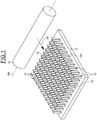
- FIG. 1 there is shown an arrangement of identical lamellae which are intended for a tire vulcanization mold and formed on a production plate 12 shown in a supposedly horizontal position.
- the plate 12 comprises an upper surface forming a working surface 12a on which are formed the lamellae 10.
- the lamellae 10 are identical to each other.
- each lamella 10 has a generally rectangular general shape of length L 10 and width l 10 .
- the length L 10 of the lamella extends substantially perpendicular to the working surface 12a of the manufacturing plate, ie here substantially vertically.
- the slats 10 are oriented or extend substantially vertically.
- the slats 10 extend longitudinally in a secant direction to the working surface 12a.
- each strip 10 here has a curved shape.
- each strip 10 comprises a main body 10a and a head 10b integral with said body.
- the body 10a comprises two opposite end faces 14, 16 opposite and two opposite end faces (not referenced) delimiting said end faces.
- the end faces 14, 16 define the thickness of the body 10a of the lamella.
- the main faces 14, 16 are substantially planar.
- the head 10b extends one end of the body 10a and extends parallel to the length of said body.
- the head 10b extends one of the end faces of the body.
- the head 10b extends laterally projecting from both sides of the body 10a.
- the head 10b protrudes from the main faces 14, 16.
- the head 10b has a more massive portion than the main body 10a.
- the head 10b here has a substantially cylindrical shape with triangular section. As a variant, the section of the head could have any other shape, for example rectangular, square, circular, etc., or alternatively in V or U.
- the lamella 10 is able to allow the molding of a sculpture of the drop type. water in the tread of the tire.
- the lower part of the body 10a is intended to be anchored in one sector of the vulcanization mold of the tire, while the upper part of the body 10a and the head 10b are intended to protrude above the molding surface of the mold sector for the molding of the sculpture in the tire strip. tire rolling.
- the procedure is as follows.
- a first step a first layer of powder is deposited on the working surface 12a of the production plate. After removal, the first layer extends substantially horizontally on the working surface 12a.
- the powder may for example be metallic or mineral, for example ceramic.
- the layering device comprises a roller 18 for distributing the powder on the working surface 12a.
- the roller 18 has the function of distributing on the working surface 12a a thin powder thickness.
- the roller 18 comprises an axis 18a of rotation and is rotatable about said axis.
- Each strip 10 is oriented perpendicularly to the axis 18a of the roller of the distribution means.
- the layering device may also comprise means for storing the powder feeding the roll.
- the device may also comprise, in combination or replacement of the roller 18, another distribution means, for example a squeegee.
- the device may further comprise a compaction roller movable together with the distribution means to make the thickness of the distributed powder even more homogeneous.
- the distribution means of the layering device are movable in translation along the working surface 12a in a direction of advance or displacement schematically illustrated. by the arrow referenced 20.
- the distribution means move substantially parallel to the working surface 12a of the plate.
- an energy source for example of the laser type, emits a laser beam whose orientation is controlled by galvanometric mirrors (not shown).
- An optical lens (not shown) is used to focus the laser beam in order to heat the powder layer in a pattern corresponding to the section of the lamella to be produced, and thus to selectively achieve the melting of the powder, and this, in each zone of the production plate 12 on which a strip 10 must be manufactured.
- a second layer is deposited on the first layer of powder that is partially fused.
- the distribution means of the layering device move substantially parallel to the direction of the largest dimension of each fused lamella section during manufacture.
- the selective melting of the second powder layer is performed.
- the length L 10 of each strip 10 produced extends substantially vertically with respect to the working surface 12a of the plate.
- the manufacture of the slats 10 is vertical type.
- the length L 10 extends substantially parallel to the stacking direction.
- the length of the manufactured slat may extend in a direction forming an angle between -20 ° and + 20 ° with the stacking direction.
- the length of the main body 10a of the lamella extends substantially vertically from the working surface 12a of the plate.
- the head 10b of the lamella also extends substantially vertically from the working surface 12a of the plate.
- the head 10b projecting from the end faces 14, 16 extends substantially perpendicular to the working surface 12a.
- the blade 10 is devoid of undercut areas, ie areas where a portion of the lamella is vertically overhanging over a zone of non-solidified powder.
- the direction of movement 20 of the distribution means of the layering device is substantially parallel to the width 10 of each sipe 10 formed.
- the direction of displacement 20 is substantially parallel to the direction of the largest dimension of the cross-section of each lamella 10.
- the direction of movement 20 is parallel to the length of each fused layer of the stack.
- side reinforcements may be provided only for a slat length greater than or equal to 30 mm and a thickness of about 0.4 mm, or for curved slats having a shift greater than 5 mm. mm between the upper and lower ends.
- each strip 10 is oriented so that the distribution means of the layering device first press on the main body 10a and then on the head 10b during their displacement in the direction 20.
- the slats 10 are arranged on the plate 12 in a matrix of columns and parallel lines which are respectively disposed transversely and parallel to the direction of movement 20 of the distribution means of the layering device.
- the lamellae 10 of each column and each row are made to be aligned relative to each other.
- Such an arrangement makes it possible to avoid deterioration of the slats during manufacture in the event of excessive friction of the distribution means on the first slats in contact with the roll.
- the lamellae are separated from the production plate, for example by cutting by electro-erosion wire.
- the slats 10 have a generally rectangular shape and are designed to allow the molding of a water drop type sculpture given the shape of the heads 10b constituting the molding parts of these slats.
- strips 10 each comprising a head 10b having other shapes, for example a corrugated head 10b as shown in FIG. figure 3 .
- the head 10b extends laterally projecting from both sides of the body 10a.
- the head 10b protrudes from the main faces 14, 16.
- strips 10 each comprising a head 10b inclined relative to the body 10a as shown in FIG. figure 4 .
- the head 10b protrudes only with respect to the main face 16.
- the design of the heads 10b of the slats is determined according to the type of sculpture to be formed in the tread.
- Each head 10b may provide at least one undercut shape and / or a more massive form than the body 10a.
- the invention has been described on the basis of a laser sintering manufacture of a tire vulcanization mold sipe.
- the invention can also be applied to other mold lining element intended to be attached to a support block of the mold, or more generally to other types of small parts used in different applications.
Description
La présente invention concerne un procédé de fabrication additive à base de poudre par frittage ou par fusion de grains de ladite poudre à l'aide d'un faisceau énergétique. Par « faisceau énergétique », on entend un rayonnement électromagnétique (par exemple un faisceau laser) ou un faisceau de particules (par exemple un faisceau d'électrons).The present invention relates to a powder-based additive manufacturing process by sintering or melting grains of said powder with the aid of an energy beam. "Energy beam" means an electromagnetic radiation (for example a laser beam) or a particle beam (for example an electron beam).
Une application particulièrement intéressante de l'invention concerne la fabrication d'éléments de garniture, tels que des lamelles, d'un moule de cuisson ou vulcanisation du type à secteurs pour pneumatiques de véhicules.A particularly advantageous application of the invention relates to the manufacture of packing elements, such as slats, of a sector-type baking or vulcanizing mold for vehicle tires.
Ce type de moule comprend principalement deux coquilles assurant chacune le moulage d'un des flancs latéraux du pneumatique, une pluralité de secteurs assurant le moulage de la bande de roulement dudit pneumatique et mobiles radialement entre une position d'ouverture et une position de fermeture du moule. Les coquilles et les secteurs définissent un espace intérieur destiné à être mis en contact avec l'ébauche du pneumatique non vulcanisée. Pour former les sculptures de la bande de roulement, des lamelles sont fixées sur les secteurs du moule et s'étendent en saillie dans cet espace intérieur. Pour plus de détails sur un moule comprenant de telles lamelles, on pourra par exemple se référer aux documents
L'intérêt de la fabrication par fusion sélective de couches de poudre superposées, plus communément nommé frittage, réside principalement dans le fait que la forme de ces lamelles peut être modélisée par ordinateur et que les lamelles peuvent ensuite être fabriquées sur la base de cette modélisation par pilotage du faisceau énergétique par l'ordinateur. En outre, cette technique est bien adaptée à la fabrication d'éléments de petites dimensions et de formes complexes, tels que les lamelles de garniture de moule, qui sont difficiles à fabriquer avec d'autres procédés.The advantage of the selective melting of superimposed powder layers, more commonly known as sintering, lies mainly in the fact that the shape of these lamellae can be modeled by computer and that the lamellae can then be manufactured on the basis of this modeling. by controlling the energy beam by the computer. In addition, this technique is well suited in the manufacture of small-sized elements and complex shapes, such as mold packing slats, which are difficult to manufacture with other methods.
Lorsque la fusion sélective est réalisée par un faisceau laser, on parle de frittage laser. La technique de frittage laser consiste à fabriquer la lamelle couche après couche, en empilant les couches de poudre consolidées et fusionnées les unes sur les autres par le faisceau laser selon une direction d'empilage. On entend par « poudre », une poudre ou un mélange de poudres. La poudre peut par exemple être métallique ou minérale, par exemple céramique.When the selective fusion is performed by a laser beam, it is called laser sintering. The laser sintering technique consists in producing the layer-by-layer lamella, stacking the consolidated powder layers and fused to one another by the laser beam in a stacking direction. The term "powder" means a powder or a mixture of powders. The powder may for example be metallic or mineral, for example ceramic.
Classiquement, pour assurer la préparation du lit de poudre préalablement à l'opération de frittage ou de la fusion, il est utilisé un dispositif de mise en couche. Un tel dispositif comprend principalement des moyens de stockage de la poudre et des moyens de répartition aptes à répartir sur un plateau de fabrication la poudre en une couche. Pour plus de détails sur de tels dispositifs de mise en couche, on pourra par exemple se référer à la demande de brevet
La première couche est déposée puis soudée directement sur le plateau de fabrication. Les autres couches sont ensuite formées successivement de manière à obtenir un empilage à partir de la première couche.The first layer is deposited and then welded directly onto the production plate. The other layers are then formed successively so as to obtain a stack from the first layer.
Généralement, la fabrication d'un élément de petite dimension, tel qu'une lamelle de garniture, s'effectue horizontalement sur le plateau de fabrication de sorte que sa longueur est sensiblement parallèle au plateau de fabrication. On parle alors d'une fabrication de type horizontale. Ceci permet d'éviter d'avoir une hauteur de lamelle trop importante et de réduire ainsi le temps de fabrication.Generally, the manufacture of a small element, such as a lining strip, is carried out horizontally on the production plate so that its length is substantially parallel to the production plate. We are talking about a horizontal type of manufacture. This makes it possible to avoid having a too large slat height and thus to reduce the manufacturing time.
Toutefois, avec un tel type de fabrication, des problèmes de non-respect des caractéristiques dimensionnelles et géométriques peuvent se poser. En effet, les lamelles peuvent présenter des ondulations ou encore des parties massives créant des zones dites en contre-dépouille, c'est-à-dire des zones où une paroi de lamelle est en surplomb au-dessus d'une zone de poudre non solidifiée. De telles parties massives sont par exemple prévues sur les lamelles décrites dans les demandes de brevet
On connait également par le document
La présente invention vise à remédier aux inconvénients précités.The present invention aims to overcome the aforementioned drawbacks.
Plus particulièrement, la présente invention vise à prévoir un procédé de fabrication additive d'au moins une pièce par frittage ou fusion de poudre à l'aide d'au moins un faisceau énergétique qui permet de garantir la fabrication satisfaisante de pièces de formes complexes pouvant par exemple présenter des ondulations et/ou des parties massives et/ou en contre-dépouille.More particularly, the present invention aims at providing a process for the additive manufacturing of at least one part by sintering or melting of powder using at least one energy beam which makes it possible to guarantee the satisfactory manufacture of pieces of complex shapes which can for example present undulations and / or solid parts and / or undercut.
Dans un mode de mise en oeuvre, le procédé concerne la fabrication additive d'au moins une pièce par frittage ou fusion de poudre à l'aide d'au moins un faisceau énergétique. La pièce comprend un corps principal pourvu de deux faces frontales opposées et une tête monobloc prolongeant une extrémité du corps, s'étendant parallèlement à la longueur dudit corps et en saillie au moins par rapport à l'une desdites faces frontales.In one embodiment, the method relates to the additive manufacturing of at least one part by sintering or melting powder using at least one energy beam. The piece comprises a main body provided with two opposite end faces and a one-piece head extending one end of the body, extending parallel to the length of said body and projecting at least with respect to one of said end faces.
Le procédé comprend les étapes suivantes:
- a) déposer au moins une couche de poudre sur une surface de travail à l'aide d'un dispositif de mise en couche comprenant des moyens de répartition de la poudre mobiles en translation le long de ladite surface,
- b) fusionner au moins en partie ladite couche déposée à l'aide du faisceau énergétique, et
- c) répéter les étapes a) et b) pour former la pièce par empilage de couches fusionnées de la pièce. Les moyens de répartition dudit dispositif sont mobiles selon une direction sensiblement parallèle à la direction de la longueur de chaque couche fusionnée. Les étapes a) et b) sont répétées pour former la pièce de sorte que la longueur de ladite pièce s'étend selon une direction sensiblement
parallèle à la direction d'empilage des couches fusionnées, et que la tête de la pièce est orientée sensiblement perpendiculairement à la surface de travail.
- a) depositing at least one layer of powder on a working surface using a layering device comprising means for distributing the powder movable in translation along said surface,
- b) at least partially fusing said deposited layer with the energy beam, and
- c) repeating steps a) and b) to form the workpiece by stacking merged layers of the workpiece. The distribution means of said device are movable in a direction substantially parallel to the direction of the length of each merged layer. Steps a) and b) are repeated to form the part so that the length of said part extends in a direction substantially
parallel to the stacking direction of the merged layers, and that the head of the workpiece is oriented substantially perpendicular to the work surface.
On entend ici par « longueur », la dimension de la pièce dans le sens de sa plus grande étendue.Here "length" is understood to mean the dimension of the part in the direction of its greatest extent.
L'orientation des couches fusionnées relativement à la direction de déplacement des moyens de répartition permet de limiter le risque de déformations des couches empilées sous l'effet des efforts appliqués par ces moyens pouvant provoquer l'apparition de concentrations de contraintes et de microfissures.The orientation of the merged layers relative to the direction of movement of the distribution means makes it possible to limit the risk of deformations of the stacked layers under the effect of the forces applied by these means which can cause the appearance of stress concentrations and microcracks.
En outre, avec cette fabrication de type verticale, l'obtention de pièces de formes complexes respectant les caractéristiques dimensionnelles, géométriques et d'état de surface requises est facilitée. Pour une pièce comprenant des parties massives, les déformations, voire les microfissures, liées aux contraintes internes générées dans la pièce par diffusion de chaleur lors des étapes de fusion sont atténuées compte tenu de l'orientation des parties massives perpendiculairement à la surface de travail, ces parties massives étant reliées à ladite surface. Pour une pièce comprenant des parties en contre-dépouille orientées perpendiculairement à la surface de travail, la rugosité n'est pas élevée contrairement à une fabrication de type horizontale dans laquelle les parties en contre-dépouille reposent sur les couches de poudre non fusionnées générant des aspérités grossières sur la pièce.In addition, with this type of vertical manufacturing, obtaining parts of complex shapes respecting the dimensional characteristics, geometric and surface required is facilitated. For a part comprising massive parts, the deformations, or even the microcracks, related to the internal stresses generated in the part by heat diffusion during the melting steps are attenuated taking into account the orientation of the solid parts perpendicular to the working surface, these massive parts being connected to said surface. For a workpiece having undercut portions oriented perpendicular to the work surface, the roughness is not high in contrast to a horizontal-type work in which the undercut portions rest on unfused powder layers generating coarse asperities on the piece.
Dans un mode de mise en oeuvre préféré, une pluralité d'empilages de couches fusionnées est formée dans des zones distinctes de la surface de travail de sorte à fabriquer simultanément une pluralité de pièces. Lesdites pièces peuvent être agencées sur la surface de travail suivant une matrice de colonnes disposées transversalement par rapport à la direction de déplacement des moyens de répartition du dispositif de mise en couche, et de lignes disposées parallèlement à ladite direction.In a preferred embodiment, a plurality of merged layer stacks are formed in separate areas of the work surface to simultaneously produce a plurality of workpieces. Said parts may be arranged on the working surface in a matrix of columns arranged transversely to the direction of movement of the distribution means of the layering device, and lines arranged parallel to said direction.
Les moyens de répartition du dispositif de mise en couche peuvent être communs à la pluralité d'empilages de couches fusionnées.The distribution means of the layering device may be common to the plurality of merged layer stacks.
Dans un mode de mise en oeuvre, les pièces de chaque colonne et de chaque ligne sont alignées les unes relativement aux autres. Alternativement, chaque pièce d'une colonne est décalée selon la direction de déplacement des moyens de répartition par rapport à la pièce immédiatement adjacente de ladite colonne.In one embodiment, the pieces of each column and each line are aligned relative to each other. Alternatively, each part of a column is shifted in the direction of displacement of the distribution means relative to the immediately adjacent part of said column.
Avantageusement, la longueur de la pièce s'étend selon une direction formant un angle comprise entre -20° et +20° avec la direction d'empilage des couches.Advantageously, the length of the piece extends in a direction forming an angle between -20 ° and + 20 ° with the stacking direction of the layers.
Dans le mode de mise en oeuvre selon l'invention, la pièce est orientée de sorte que les moyens de répartition du dispositif de mise en couche appuient d'abord sur le corps principal puis ensuite sur la tête de ladite pièce lors de leur déplacement.In the embodiment according to the invention, the part is oriented so that the distribution means of the layering device first press on the main body and then on the head of said part during their displacement.
Dans un mode de mise en oeuvre, les moyens de répartition du dispositif de mise en couche comprennent au moins un rouleau. De préférence, l'axe du rouleau est orienté sensiblement perpendiculairement à la direction de la longueur de chaque couche fusionnée de la pièce. Ladite pièce peut présenter globalement une forme rectangulaire.In one embodiment, the distribution means of the layering device comprise at least one roller. Preferably, the axis of the roll is oriented substantially perpendicular to the direction of the length of each fused layer of the workpiece. Said part may generally have a rectangular shape.
D'autres buts, caractéristiques et avantages apparaîtront à la lecture de la description détaillée suivante donnée uniquement en tant qu'exemple non limitatif et faite en référence aux dessins annexés sur lesquels :
- la
figure 1 est une vue schématique en perspective illustrant partiellement un procédé de fabrication de lamelles par frittage laser selon un premier exemple de mise en oeuvre, - la
figure 2 est une vue de détail de deux lamelles de lafigure 1 , et - les
figures 3 et 4 sont des vues de détail de deux lamelles selon des deuxième et troisième exemples de mise en oeuvre du procédé.
- the
figure 1 is a schematic perspective view partially illustrating a method of manufacturing lamellae by laser sintering according to a first example of implementation, - the
figure 2 is a detail view of two slats of thefigure 1 , and - the
Figures 3 and 4 are detailed views of two slats according to second and third examples of implementation of the method.
Sur la
Comme illustré plus visiblement à la
La lamelle 10 présente ici une forme courbe. Dans l'exemple de réalisation illustré, chaque lamelle 10 comprend un corps 10a principal et une tête 10b monobloc avec ledit corps. Le corps 10a comprend deux faces frontales 14, 16 principales opposées et deux faces d'extrémité (non référencées) latérales opposées délimitant lesdites faces frontales. Les faces frontales 14, 16 délimitent l'épaisseur du corps 10a de la lamelle. Dans l'exemple de réalisation illustré, les faces principales 14, 16 sont sensiblement planes.The
La tête 10b prolonge une extrémité du corps 10a et s'étend parallèlement à la longueur dudit corps. La tête 10b prolonge une des faces d'extrémité du corps. La tête 10b s'étend en saillie latéralement de part et d'autre du corps 10a. La tête 10b s'étend en saillie par rapport aux faces principales 14, 16. La tête 10b présente une partie plus massive que le corps 10a principal. La tête 10b présente ici une forme sensiblement cylindrique à section triangulaire. En variante, la section de la tête pourrait avoir toute autre forme par exemple rectangulaire, carré, circulaire, etc., ou encore en V ou en U. La lamelle 10 est apte à permettre le moulage d'une sculpture de type goutte d'eau dans la bande de roulement du pneumatique. Plus précisément, la partie inférieure du corps 10a est destinée à être ancrée dans un secteur du moule de vulcanisation du pneumatique, tandis que la partie supérieure du corps 10a et la tête 10b sont destinées à venir en saillie au-dessus de la surface de moulage du secteur du moule pour le moulage de la sculpture dans la bande de roulement du pneumatique.The
Pour la fabrication de la pluralité de lamelles 10, on procède de la manière suivante. Dans une première étape, on dépose une première couche de poudre sur la surface de travail 12a du plateau de fabrication. Après dépose, la première couche s'étend sensiblement horizontalement sur la surface de travail 12a. La poudre peut par exemple être métallique ou minérale, par exemple céramique.For the manufacture of the plurality of
L'ensemble des moyens permettant l'application d'une couche de poudre sur la surface de travail 12a du plateau de fabrication est appelé dispositif de mise en couche. Le dispositif de mise en couche comprend un rouleau 18 de répartition de la poudre sur la surface de travail 12a. Le rouleau 18 a pour fonction de répartir sur la surface de travail 12a une mince épaisseur de poudre. Le rouleau 18 comprend un axe 18a de rotation et est mobile à rotation autour dudit axe. Chaque lamelle 10 est orientée perpendiculairement à l'axe 18a du rouleau des moyens de répartition.All the means for applying a layer of powder on the working
Le dispositif de mise en couche peut également comprendre des moyens de stockage de la poudre alimentant le rouleau. Le dispositif peut encore comprendre, en combinaison ou en remplacement du rouleau 18, un autre moyen de répartition par exemple une raclette. Le dispositif peut encore comprendre un rouleau de compactage mobile conjointement avec le moyen de répartition pour rendre encore plus homogène l'épaisseur de la poudre répartie.The layering device may also comprise means for storing the powder feeding the roll. The device may also comprise, in combination or replacement of the
Lors de cette étape de dépose de la première couche sur le plateau de fabrication 12, les moyens de répartition du dispositif de mise en couche sont mobiles en translation le long de la surface de travail 12a selon une direction d'avance ou de déplacement illustrée schématiquement par la flèche référencée 20. Les moyens de répartition se déplacent sensiblement parallèlement à la surface de travail 12a du plateau.During this step of removing the first layer on the
Dans une seconde étape, une source énergétique (non représentée) par exemple du type laser, émet un faisceau laser dont l'orientation est contrôlée par des miroirs galvanométriques (non représentés). Une lentille optique (non représentée) permet de focaliser le faisceau laser afin de chauffer la couche de poudre selon un motif correspondant à la section de la lamelle à fabriquer, et ainsi réaliser de manière sélective la fusion de la poudre, et ce, dans chaque zone du plateau de fabrication 12 sur laquelle doit être fabriquée une lamelle 10.In a second step, an energy source (not shown), for example of the laser type, emits a laser beam whose orientation is controlled by galvanometric mirrors (not shown). An optical lens (not shown) is used to focus the laser beam in order to heat the powder layer in a pattern corresponding to the section of the lamella to be produced, and thus to selectively achieve the melting of the powder, and this, in each zone of the
Lors d'une troisième étape, après l'étape de traitement par laser, une seconde couche est déposée sur la première couche de poudre qui est en partie fusionnée. Les moyens de répartition du dispositif de mise en couche se déplacent sensiblement parallèlement à la direction de la plus grande dimension de chaque section fusionnée de lamelle en cours de fabrication. Ensuite, la fusion sélective de la seconde couche de poudre est réalisée. Ces étapes sont à nouveau répétées pour former par empilage de couches les lamelles 10. Les couches fusionnées de chaque lamelle 10 s'étendent sensiblement horizontalement et sont empilées les unes sur les autres selon une direction d'empilage sensiblement verticale.In a third step, after the laser treatment step, a second layer is deposited on the first layer of powder that is partially fused. The distribution means of the layering device move substantially parallel to the direction of the largest dimension of each fused lamella section during manufacture. Then the selective melting of the second powder layer is performed. These steps are repeated again to form the
Comme indiqué précédemment, la longueur L10 de chaque lamelle 10 fabriquée s'étend sensiblement verticalement par rapport à la surface de travail 12a du plateau. La fabrication des lamelles 10 est de type verticale. La longueur L10 s'étend sensiblement parallèlement à la direction d'empilage. La longueur de la lamelle fabriquée peut s'étendre selon une direction formant un angle compris entre -20° et + 20° avec la direction d'empilage. La longueur du corps 10a principal de la lamelle s'étend sensiblement verticalement à partir de la surface de travail 12a du plateau. La tête 10b de la lamelle s'étend également sensiblement verticalement à partir de la surface de travail 12a du plateau. La tête 10b en saillie par rapport aux faces frontales 14, 16 s'étend sensiblement perpendiculairement par rapport à la surface de travail 12a. Ainsi, la lamelle 10 est dépourvue de zones en contre-dépouille, i.e. de zones où une partie de la lamelle est verticalement en surplomb au-dessus d'une zone de poudre non solidifiée.As indicated above, the length L 10 of each
La direction de déplacement 20 des moyens de répartition du dispositif de mise en couche est sensiblement parallèle à la largeur l10 de chaque lamelle 10 formée. La direction de déplacement 20 est sensiblement parallèle à la direction de la plus grande dimension de la section transversale de chaque lamelle 10. Pour une lamelle 10, la direction de déplacement 20 est parallèle à la longueur de chaque couche fusionnée de l'empilage.The direction of
Grâce à l'orientation des couches fusionnées pour la fabrication de chaque lamelle 10 par rapport à la direction de déplacement 20 des moyens de répartition du dispositif de mise en couche, le risque de déformations, notamment par flexion, pouvant provoquer l'apparition de phénomènes de concentrations de contraintes et de micro fissures est limité lors du passage de ces moyens sur chaque couche. En outre, cette orientation permet d'obtenir un bon encaissement des efforts appliqués par les moyens de répartition avec cette fabrication de type verticale de la lamelle. Avec ce type de fabrication, l'obtention de pièces de formes complexes respectant les caractéristiques dimensionnelles, géométriques et d'état de surface requises est facilitée.Due to the orientation of the merged layers for the manufacture of each
Ainsi, pour la majorité de lamelles 10, il n'est pas nécessaire de prévoir la formation de renforts se présentant sous forme de surépaisseurs venues de matière avec la lamelle. A titre indicatif, avec de telles lamelles, des renforts latéraux peuvent être prévus seulement pour une longueur de lamelle supérieure ou égale à 30 mm et une épaisseur de l'ordre de 0.4 mm, ou encore pour les lamelles courbes présentant un décalage supérieure à 5 mm entre les extrémité supérieure et inférieure.Thus, for the majority of
Par ailleurs, chaque lamelle 10 est orientée de sorte que les moyens de répartition du dispositif de mise en couche appuient d'abord sur le corps principal 10a puis ensuite sur la tête 10b lors de leur déplacement selon la direction 20.Furthermore, each
Ceci permet une augmentation progressive des frottements entre le rouleau du dispositif de mise en couche et les lamelles 10 en cours de fabrication. En effet, si le rouleau passe d'abord sur les têtes 10b des lamelles et ensuite sur leurs corps 10a, le rouleau subit brusquement d'importants frottements, ce qui peut conduire à endommager les lamelles 10 fabriquées et éventuellement à bloquer le rouleau et donc provoquer l'arrêt de la machine.This allows a gradual increase in friction between the roll of the layering device and the
Comme illustré à la
Dans l'exemple de réalisation illustré, les lamelles 10 présentent une forme générale rectangulaire et sont conçues pour permettre le moulage d'une sculpture de type goutte d'eau étant donné la forme des têtes 10b constituant les parties de moulage de ces lamelles.In the exemplary embodiment illustrated, the
En variante, il est possible de fabriquer des lamelles 10 comprenant chacune une tête 10b présentant d'autres formes, par exemple une tête 10b ondulée comme cela est représenté à la
Dans une autre variante, il est encore possible de fabriquer des lamelles 10 comprenant chacune une tête 10b inclinée par rapport au corps 10a comme cela est illustré à la
L'invention a été décrite sur la base d'une fabrication par frittage laser d'une lamelle pour moule de vulcanisation de pneumatiques. L'invention peut également être appliquée à autre élément de garniture du moule destiné à être rapporté sur un bloc support du moule, ou plus généralement à d'autres types de pièces de petites dimensions utilisées dans des applications différentes.The invention has been described on the basis of a laser sintering manufacture of a tire vulcanization mold sipe. The invention can also be applied to other mold lining element intended to be attached to a support block of the mold, or more generally to other types of small parts used in different applications.
Claims (10)
- Process for the additive manufacturing of at least one part by powder sintering or melting using at least one beam of energy, said part comprising a main body provided with two opposite frontal faces and a one-piece head prolonging one end of the body, extending parallel to the length of said body and jutting out at least with respect to one of said frontal faces, said process comprising the following steps:- a) depositing at least one layer of powder on a working surface using a layering device comprising translatably mobile means for distributing the powder along said surface, and- b) at least partly fusing said layer deposited using the beam of energy,- c) repeating steps a) and b) in order to form the part by stacking of fused layers, said process being characterized in that:- the distribution means of said device are mobile in a direction substantially parallel to the direction of the length of each fused layer of the part,- steps a) and b) are repeated in order to form the part so that the length of said part extends along a direction substantially parallel to the stacking direction of the fused layers and so that the head of the part is oriented substantially perpendicular to the working surface, and- the part is oriented so that the distribution means of the layering device bear firstly against the main body then next against the head of said part during the displacement thereof.
- Process according to Claim 1, in which a plurality of stacks of fused layers is formed in different zones of the working surface so as to simultaneously manufacture a plurality of parts.
- Process according to Claim 2, in which the plurality of parts is arranged on the working surface as a matrix of columns positioned transversely relative to the displacement direction of the distribution means of the layering device, and of rows positioned parallel to said direction.
- Process according to Claim 2 or 3, in which the distribution means of the layering device are shared by the plurality of stacks of fused layers.
- Process according to Claim 3 or 4, in which the parts of each column and of each row are aligned relative to one another.
- Process according to Claim 3 or 4, in which each part of a column is offset along the displacement direction of the distribution means relative to the immediately adjacent part of said column.
- Process according to any one of the preceding claims, in which the length of the part extends along a direction forming an angle of between -20° and +20° with the stacking direction of the layers.
- Process according to any one of the preceding claims, in which the distribution means of the layering device comprise at least one roller.
- Process according to Claim 8, in which the axis of the roller is oriented substantially perpendicular to the direction of the length of each fused layer of the part.
- Process according to any one of the preceding claims, in which the part generally has a rectangular shape.
Applications Claiming Priority (2)
| Application Number | Priority Date | Filing Date | Title |
|---|---|---|---|
| FR1457259A FR3024059A1 (en) | 2014-07-28 | 2014-07-28 | PROCESS FOR THE ADDITIVE MANUFACTURE OF A POWDER OF A PIECE, IN PARTICULAR A PADDING LAMINATE FOR A PNEUMATIC MOLD |
| PCT/EP2015/067041 WO2016016136A1 (en) | 2014-07-28 | 2015-07-24 | Powder additive method for manufacturing a part, in particular a sipe for lining a tyre mould |
Publications (2)
| Publication Number | Publication Date |
|---|---|
| EP3174652A1 EP3174652A1 (en) | 2017-06-07 |
| EP3174652B1 true EP3174652B1 (en) | 2018-09-12 |
Family
ID=51688277
Family Applications (1)
| Application Number | Title | Priority Date | Filing Date |
|---|---|---|---|
| EP15742022.5A Active EP3174652B1 (en) | 2014-07-28 | 2015-07-24 | Powder additive method for manufacturing a part, in particular a sipe for lining a tyre mould |
Country Status (7)
| Country | Link |
|---|---|
| US (1) | US10525532B2 (en) |
| EP (1) | EP3174652B1 (en) |
| JP (1) | JP6702936B2 (en) |
| KR (1) | KR102330988B1 (en) |
| CN (1) | CN106573414B (en) |
| FR (1) | FR3024059A1 (en) |
| WO (1) | WO2016016136A1 (en) |
Families Citing this family (11)
| Publication number | Priority date | Publication date | Assignee | Title |
|---|---|---|---|---|
| FR3049896A1 (en) | 2016-04-08 | 2017-10-13 | Michelin & Cie | TIRE TREAD TIRE |
| BE1024640B1 (en) * | 2016-10-13 | 2018-05-16 | Safran Aero Boosters S.A. | PROCESS FOR THE ADDITIVE MANUFACTURE OF TURBOMACHINE OIL TANK |
| FR3070898A1 (en) | 2017-09-13 | 2019-03-15 | Compagnie Generale Des Etablissements Michelin | TIRE TREAD BAND COMPRISING HIDDEN CHANNELS. |
| CN108213426B (en) * | 2018-01-09 | 2021-02-19 | 北京化工大学 | Manufacturing method of recyclable tire mold based on additive manufacturing technology |
| JP7060982B2 (en) * | 2018-02-22 | 2022-04-27 | 三桜工業株式会社 | Bending die and manufacturing method of bending die |
| DE102018204024A1 (en) * | 2018-03-16 | 2019-09-19 | Continental Reifen Deutschland Gmbh | Rib or lamellar element, profile ring segment and method for producing a profile ring segment |
| FR3080306B1 (en) | 2018-04-19 | 2021-02-19 | Michelin & Cie | ADDITIVE MANUFACTURING PROCESS OF A METAL PART IN THREE DIMENSIONS |
| DE102020201682A1 (en) * | 2020-02-11 | 2021-08-12 | Continental Reifen Deutschland Gmbh | Method for producing a mold segment of a vulcanization mold, mold segment and vulcanization mold |
| CN111604656B (en) * | 2020-06-05 | 2021-05-25 | 山东玲珑机电有限公司 | Method for processing pattern block of tire mold |
| FR3113472B1 (en) * | 2020-08-19 | 2023-02-10 | Michelin & Cie | Curing mold for a tire comprising means for cutting out a burr of rubber |
| FR3124803B1 (en) | 2021-06-30 | 2023-10-06 | Michelin & Cie | Austenitic stainless steel powder and its production process |
Family Cites Families (14)
| Publication number | Priority date | Publication date | Assignee | Title |
|---|---|---|---|---|
| US5155324A (en) * | 1986-10-17 | 1992-10-13 | Deckard Carl R | Method for selective laser sintering with layerwise cross-scanning |
| DE19529741A1 (en) | 1995-08-12 | 1997-02-13 | Bayerische Motoren Werke Ag | Device for the wireless exchange of data between a service facility and a control unit in a motor vehicle |
| IT1290210B1 (en) * | 1997-01-29 | 1998-10-22 | Pirelli | METHOD FOR THE PRODUCTION OF TIRES, FOR THE REALIZATION OF VULCANIZATION MOLDS FOR SAID TIRES, TIRES AND MOLDS SO |
| JP3811045B2 (en) | 2001-03-27 | 2006-08-16 | 日本碍子株式会社 | Sipe blade molding die and manufacturing method thereof |
| DE10219983B4 (en) * | 2002-05-03 | 2004-03-18 | Bego Medical Ag | Process for manufacturing products using free-form laser sintering |
| JP4351998B2 (en) * | 2002-07-23 | 2009-10-28 | ユニバーシティ オブ サザン カリフォルニア | Manufacture of metal parts using the selective inhibition of sintering (SIS) method |
| US7509725B2 (en) * | 2005-04-22 | 2009-03-31 | The Boeing Company | Design methodology to maximize the application of direct manufactured aerospace parts |
| US9022083B2 (en) | 2008-09-11 | 2015-05-05 | Michelin Recherche Et Technique S.A. | Variable surface area tire tread and tire |
| FR2961741B1 (en) * | 2010-06-25 | 2012-08-03 | Michelin Soc Tech | LAMELLE FOR A TRIM OF A MOLD FOR THE VULCANIZATION OF A TIRE TREAD OF A TIRE |
| FR2962061B1 (en) * | 2010-07-01 | 2013-02-22 | Snecma | METHOD FOR MANUFACTURING A METAL PIECE BY SELECTIVE FUSION OF A POWDER |
| FR2974316B1 (en) | 2011-04-19 | 2015-10-09 | Phenix Systems | PROCESS FOR PRODUCING AN OBJECT BY SOLIDIFYING A POWDER USING A LASER |
| FR2981867B1 (en) * | 2011-10-26 | 2016-02-12 | Snecma | PROCESS FOR MANUFACTURING A METAL PIECE FOR AIRCRAFT TURBOJET ENGINE |
| FR2991208B1 (en) | 2012-06-01 | 2014-06-06 | Michelin & Cie | MACHINE AND PROCESS FOR ADDITIVE MANUFACTURE OF POWDER |
| FR2991613B1 (en) * | 2012-06-06 | 2016-11-11 | Snecma | PROCESS FOR MANUFACTURING PIECE BY SELECTIVE FUSION OR SELECTIVE SINTING OF POWDER BEDS (S) BY MEANS OF A HIGH ENERGY BEAM |
-
2014
- 2014-07-28 FR FR1457259A patent/FR3024059A1/en not_active Withdrawn
-
2015
- 2015-07-24 US US15/329,782 patent/US10525532B2/en active Active
- 2015-07-24 JP JP2017505177A patent/JP6702936B2/en active Active
- 2015-07-24 WO PCT/EP2015/067041 patent/WO2016016136A1/en active Application Filing
- 2015-07-24 CN CN201580041446.1A patent/CN106573414B/en active Active
- 2015-07-24 EP EP15742022.5A patent/EP3174652B1/en active Active
- 2015-07-24 KR KR1020177005110A patent/KR102330988B1/en active IP Right Grant
Also Published As
| Publication number | Publication date |
|---|---|
| KR102330988B1 (en) | 2021-11-25 |
| CN106573414A (en) | 2017-04-19 |
| JP6702936B2 (en) | 2020-06-03 |
| WO2016016136A1 (en) | 2016-02-04 |
| CN106573414B (en) | 2019-06-07 |
| EP3174652A1 (en) | 2017-06-07 |
| JP2017530255A (en) | 2017-10-12 |
| US10525532B2 (en) | 2020-01-07 |
| FR3024059A1 (en) | 2016-01-29 |
| US20170216922A1 (en) | 2017-08-03 |
| KR20170038859A (en) | 2017-04-07 |
Similar Documents
| Publication | Publication Date | Title |
|---|---|---|
| EP3174652B1 (en) | Powder additive method for manufacturing a part, in particular a sipe for lining a tyre mould | |
| EP3174653B1 (en) | Method for the powder-based additive manufacture of a component, notably a sype-moulding tyre-mould liner, with an asociated reinforcing element | |
| EP3370901B1 (en) | Method for additive manufacturing of a part, in particular a lining element for a tyre mould, using powder | |
| EP2699369B1 (en) | Process for manufacturing an object by solidifying a powder using a laser | |
| EP2454040B1 (en) | Device for forming thin films and method for using such a device | |
| EP2382065B1 (en) | Method of manufacturing a cover element and a support element which are intended for a tyre mould | |
| WO2017118806A1 (en) | Method for manufacturing a workpiece by additive manufacturing | |
| EP2701892A1 (en) | Method for manufacturing an object by solidifying powder using a laser beam with the insertion of a member for absorbing deformations | |
| FR2939713A1 (en) | FITTING ELEMENT COMPRISING A SHELL AND A CORE | |
| WO2012156439A1 (en) | Method for manufacturing a molding element by fritting with a completely planar unfritted portion, and corresponding molding element | |
| CA2853381A1 (en) | Apparatus for manufacturing parts by selective melting of powder | |
| WO2016110562A1 (en) | Matrix element for tyre mould and associated manufacturing method | |
| EP3509774A1 (en) | Method for manufacturing a part of electroconductive material by additive manufacturing | |
| WO2017121746A1 (en) | Method and facility for manufacturing a three-dimensional object | |
| EP3624967A1 (en) | Method for creating an aircraft turbomachine vane using additive manufacturing | |
| FR3053632A1 (en) | ADDITIVE MANUFACTURING METHOD WITH REMOVAL OF MATERIAL BETWEEN TWO LAYERS | |
| FR3029446A1 (en) | MOLD FOR MANUFACTURING A PLASTIC PART COMPRISING A SYSTEM FOR REALIZING ORIFICES IN THE WORKPIECE | |
| WO2023175263A1 (en) | Method for manufacturing a turbomachine blade | |
| FR3102078A1 (en) | INSTALLATION AND ADDITIVE MANUFACTURING PROCESS ON BED OF POWDER OF PART WITH IMPROVED SURFACE CONDITION | |
| FR3139868A1 (en) | Anchor strip and method of manufacturing such an anchor strip | |
| WO2018007769A1 (en) | Additive manufacturing process using discrete surface elements |
Legal Events
| Date | Code | Title | Description |
|---|---|---|---|
| STAA | Information on the status of an ep patent application or granted ep patent |
Free format text: STATUS: THE INTERNATIONAL PUBLICATION HAS BEEN MADE |
|
| 17P | Request for examination filed |
Effective date: 20170125 |
|
| AK | Designated contracting states |
Kind code of ref document: A1 Designated state(s): AL AT BE BG CH CY CZ DE DK EE ES FI FR GB GR HR HU IE IS IT LI LT LU LV MC MK MT NL NO PL PT RO RS SE SI SK SM TR |
|
| AX | Request for extension of the european patent |
Extension state: BA ME |
|
| PUAI | Public reference made under article 153(3) epc to a published international application that has entered the european phase |
Free format text: ORIGINAL CODE: 0009012 |
|
| STAA | Information on the status of an ep patent application or granted ep patent |
Free format text: STATUS: REQUEST FOR EXAMINATION WAS MADE |
|
| RAP1 | Party data changed (applicant data changed or rights of an application transferred) |
Owner name: COMPAGNIE GENERALE DES ETABLISSEMENTS MICHELIN |
|
| RAP1 | Party data changed (applicant data changed or rights of an application transferred) |
Owner name: COMPAGNIE GENERALE DES ETABLISSEMENTS MICHELIN |
|
| DAV | Request for validation of the european patent (deleted) | ||
| DAX | Request for extension of the european patent (deleted) | ||
| GRAP | Despatch of communication of intention to grant a patent |
Free format text: ORIGINAL CODE: EPIDOSNIGR1 |
|
| STAA | Information on the status of an ep patent application or granted ep patent |
Free format text: STATUS: GRANT OF PATENT IS INTENDED |
|
| RIC1 | Information provided on ipc code assigned before grant |
Ipc: B22F 3/105 20060101AFI20180329BHEP Ipc: B29C 64/153 20170101ALI20180329BHEP Ipc: B33Y 80/00 20150101ALN20180329BHEP Ipc: B29D 30/06 20060101ALI20180329BHEP Ipc: B33Y 10/00 20150101ALI20180329BHEP |
|
| INTG | Intention to grant announced |
Effective date: 20180425 |
|
| GRAS | Grant fee paid |
Free format text: ORIGINAL CODE: EPIDOSNIGR3 |
|
| GRAA | (expected) grant |
Free format text: ORIGINAL CODE: 0009210 |
|
| STAA | Information on the status of an ep patent application or granted ep patent |
Free format text: STATUS: THE PATENT HAS BEEN GRANTED |
|
| AK | Designated contracting states |
Kind code of ref document: B1 Designated state(s): AL AT BE BG CH CY CZ DE DK EE ES FI FR GB GR HR HU IE IS IT LI LT LU LV MC MK MT NL NO PL PT RO RS SE SI SK SM TR |
|
| REG | Reference to a national code |
Ref country code: GB Ref legal event code: FG4D Free format text: NOT ENGLISH |
|
| REG | Reference to a national code |
Ref country code: CH Ref legal event code: EP |
|
| REG | Reference to a national code |
Ref country code: IE Ref legal event code: FG4D Free format text: LANGUAGE OF EP DOCUMENT: FRENCH |
|
| REG | Reference to a national code |
Ref country code: DE Ref legal event code: R096 Ref document number: 602015016156 Country of ref document: DE |
|
| REG | Reference to a national code |
Ref country code: AT Ref legal event code: REF Ref document number: 1039946 Country of ref document: AT Kind code of ref document: T Effective date: 20181015 |
|
| RAP2 | Party data changed (patent owner data changed or rights of a patent transferred) |
Owner name: COMPAGNIE GENERALE DES ETABLISSEMENTS MICHELIN |
|
| REG | Reference to a national code |
Ref country code: SE Ref legal event code: TRGR |
|
| REG | Reference to a national code |
Ref country code: NL Ref legal event code: MP Effective date: 20180912 |
|
| REG | Reference to a national code |
Ref country code: LT Ref legal event code: MG4D |
|
| PG25 | Lapsed in a contracting state [announced via postgrant information from national office to epo] |
Ref country code: BG Free format text: LAPSE BECAUSE OF FAILURE TO SUBMIT A TRANSLATION OF THE DESCRIPTION OR TO PAY THE FEE WITHIN THE PRESCRIBED TIME-LIMIT Effective date: 20181212 Ref country code: LT Free format text: LAPSE BECAUSE OF FAILURE TO SUBMIT A TRANSLATION OF THE DESCRIPTION OR TO PAY THE FEE WITHIN THE PRESCRIBED TIME-LIMIT Effective date: 20180912 Ref country code: FI Free format text: LAPSE BECAUSE OF FAILURE TO SUBMIT A TRANSLATION OF THE DESCRIPTION OR TO PAY THE FEE WITHIN THE PRESCRIBED TIME-LIMIT Effective date: 20180912 Ref country code: RS Free format text: LAPSE BECAUSE OF FAILURE TO SUBMIT A TRANSLATION OF THE DESCRIPTION OR TO PAY THE FEE WITHIN THE PRESCRIBED TIME-LIMIT Effective date: 20180912 Ref country code: GR Free format text: LAPSE BECAUSE OF FAILURE TO SUBMIT A TRANSLATION OF THE DESCRIPTION OR TO PAY THE FEE WITHIN THE PRESCRIBED TIME-LIMIT Effective date: 20181213 Ref country code: NO Free format text: LAPSE BECAUSE OF FAILURE TO SUBMIT A TRANSLATION OF THE DESCRIPTION OR TO PAY THE FEE WITHIN THE PRESCRIBED TIME-LIMIT Effective date: 20181212 |
|
| PG25 | Lapsed in a contracting state [announced via postgrant information from national office to epo] |
Ref country code: AL Free format text: LAPSE BECAUSE OF FAILURE TO SUBMIT A TRANSLATION OF THE DESCRIPTION OR TO PAY THE FEE WITHIN THE PRESCRIBED TIME-LIMIT Effective date: 20180912 Ref country code: HR Free format text: LAPSE BECAUSE OF FAILURE TO SUBMIT A TRANSLATION OF THE DESCRIPTION OR TO PAY THE FEE WITHIN THE PRESCRIBED TIME-LIMIT Effective date: 20180912 Ref country code: LV Free format text: LAPSE BECAUSE OF FAILURE TO SUBMIT A TRANSLATION OF THE DESCRIPTION OR TO PAY THE FEE WITHIN THE PRESCRIBED TIME-LIMIT Effective date: 20180912 |
|
| REG | Reference to a national code |
Ref country code: AT Ref legal event code: MK05 Ref document number: 1039946 Country of ref document: AT Kind code of ref document: T Effective date: 20180912 |
|
| PG25 | Lapsed in a contracting state [announced via postgrant information from national office to epo] |
Ref country code: PL Free format text: LAPSE BECAUSE OF FAILURE TO SUBMIT A TRANSLATION OF THE DESCRIPTION OR TO PAY THE FEE WITHIN THE PRESCRIBED TIME-LIMIT Effective date: 20180912 Ref country code: NL Free format text: LAPSE BECAUSE OF FAILURE TO SUBMIT A TRANSLATION OF THE DESCRIPTION OR TO PAY THE FEE WITHIN THE PRESCRIBED TIME-LIMIT Effective date: 20180912 Ref country code: RO Free format text: LAPSE BECAUSE OF FAILURE TO SUBMIT A TRANSLATION OF THE DESCRIPTION OR TO PAY THE FEE WITHIN THE PRESCRIBED TIME-LIMIT Effective date: 20180912 Ref country code: AT Free format text: LAPSE BECAUSE OF FAILURE TO SUBMIT A TRANSLATION OF THE DESCRIPTION OR TO PAY THE FEE WITHIN THE PRESCRIBED TIME-LIMIT Effective date: 20180912 Ref country code: EE Free format text: LAPSE BECAUSE OF FAILURE TO SUBMIT A TRANSLATION OF THE DESCRIPTION OR TO PAY THE FEE WITHIN THE PRESCRIBED TIME-LIMIT Effective date: 20180912 Ref country code: CZ Free format text: LAPSE BECAUSE OF FAILURE TO SUBMIT A TRANSLATION OF THE DESCRIPTION OR TO PAY THE FEE WITHIN THE PRESCRIBED TIME-LIMIT Effective date: 20180912 Ref country code: ES Free format text: LAPSE BECAUSE OF FAILURE TO SUBMIT A TRANSLATION OF THE DESCRIPTION OR TO PAY THE FEE WITHIN THE PRESCRIBED TIME-LIMIT Effective date: 20180912 Ref country code: IS Free format text: LAPSE BECAUSE OF FAILURE TO SUBMIT A TRANSLATION OF THE DESCRIPTION OR TO PAY THE FEE WITHIN THE PRESCRIBED TIME-LIMIT Effective date: 20190112 |
|
| PG25 | Lapsed in a contracting state [announced via postgrant information from national office to epo] |
Ref country code: SK Free format text: LAPSE BECAUSE OF FAILURE TO SUBMIT A TRANSLATION OF THE DESCRIPTION OR TO PAY THE FEE WITHIN THE PRESCRIBED TIME-LIMIT Effective date: 20180912 Ref country code: PT Free format text: LAPSE BECAUSE OF FAILURE TO SUBMIT A TRANSLATION OF THE DESCRIPTION OR TO PAY THE FEE WITHIN THE PRESCRIBED TIME-LIMIT Effective date: 20190112 Ref country code: SM Free format text: LAPSE BECAUSE OF FAILURE TO SUBMIT A TRANSLATION OF THE DESCRIPTION OR TO PAY THE FEE WITHIN THE PRESCRIBED TIME-LIMIT Effective date: 20180912 |
|
| REG | Reference to a national code |
Ref country code: DE Ref legal event code: R097 Ref document number: 602015016156 Country of ref document: DE |
|
| PLBE | No opposition filed within time limit |
Free format text: ORIGINAL CODE: 0009261 |
|
| STAA | Information on the status of an ep patent application or granted ep patent |
Free format text: STATUS: NO OPPOSITION FILED WITHIN TIME LIMIT |
|
| PG25 | Lapsed in a contracting state [announced via postgrant information from national office to epo] |
Ref country code: DK Free format text: LAPSE BECAUSE OF FAILURE TO SUBMIT A TRANSLATION OF THE DESCRIPTION OR TO PAY THE FEE WITHIN THE PRESCRIBED TIME-LIMIT Effective date: 20180912 |
|
| 26N | No opposition filed |
Effective date: 20190613 |
|
| PG25 | Lapsed in a contracting state [announced via postgrant information from national office to epo] |
Ref country code: SI Free format text: LAPSE BECAUSE OF FAILURE TO SUBMIT A TRANSLATION OF THE DESCRIPTION OR TO PAY THE FEE WITHIN THE PRESCRIBED TIME-LIMIT Effective date: 20180912 |
|
| PG25 | Lapsed in a contracting state [announced via postgrant information from national office to epo] |
Ref country code: MC Free format text: LAPSE BECAUSE OF FAILURE TO SUBMIT A TRANSLATION OF THE DESCRIPTION OR TO PAY THE FEE WITHIN THE PRESCRIBED TIME-LIMIT Effective date: 20180912 |
|
| REG | Reference to a national code |
Ref country code: CH Ref legal event code: PL |
|
| GBPC | Gb: european patent ceased through non-payment of renewal fee |
Effective date: 20190724 |
|
| PG25 | Lapsed in a contracting state [announced via postgrant information from national office to epo] |
Ref country code: TR Free format text: LAPSE BECAUSE OF FAILURE TO SUBMIT A TRANSLATION OF THE DESCRIPTION OR TO PAY THE FEE WITHIN THE PRESCRIBED TIME-LIMIT Effective date: 20180912 |
|
| REG | Reference to a national code |
Ref country code: BE Ref legal event code: MM Effective date: 20190731 |
|
| PG25 | Lapsed in a contracting state [announced via postgrant information from national office to epo] |
Ref country code: GB Free format text: LAPSE BECAUSE OF NON-PAYMENT OF DUE FEES Effective date: 20190724 |
|
| PG25 | Lapsed in a contracting state [announced via postgrant information from national office to epo] |
Ref country code: BE Free format text: LAPSE BECAUSE OF NON-PAYMENT OF DUE FEES Effective date: 20190731 Ref country code: LI Free format text: LAPSE BECAUSE OF NON-PAYMENT OF DUE FEES Effective date: 20190731 Ref country code: LU Free format text: LAPSE BECAUSE OF NON-PAYMENT OF DUE FEES Effective date: 20190724 Ref country code: CH Free format text: LAPSE BECAUSE OF NON-PAYMENT OF DUE FEES Effective date: 20190731 |
|
| PG25 | Lapsed in a contracting state [announced via postgrant information from national office to epo] |
Ref country code: IE Free format text: LAPSE BECAUSE OF NON-PAYMENT OF DUE FEES Effective date: 20190724 |
|
| PG25 | Lapsed in a contracting state [announced via postgrant information from national office to epo] |
Ref country code: CY Free format text: LAPSE BECAUSE OF FAILURE TO SUBMIT A TRANSLATION OF THE DESCRIPTION OR TO PAY THE FEE WITHIN THE PRESCRIBED TIME-LIMIT Effective date: 20180912 |
|
| PG25 | Lapsed in a contracting state [announced via postgrant information from national office to epo] |
Ref country code: HU Free format text: LAPSE BECAUSE OF FAILURE TO SUBMIT A TRANSLATION OF THE DESCRIPTION OR TO PAY THE FEE WITHIN THE PRESCRIBED TIME-LIMIT; INVALID AB INITIO Effective date: 20150724 Ref country code: MT Free format text: LAPSE BECAUSE OF FAILURE TO SUBMIT A TRANSLATION OF THE DESCRIPTION OR TO PAY THE FEE WITHIN THE PRESCRIBED TIME-LIMIT Effective date: 20180912 |
|
| PG25 | Lapsed in a contracting state [announced via postgrant information from national office to epo] |
Ref country code: MK Free format text: LAPSE BECAUSE OF FAILURE TO SUBMIT A TRANSLATION OF THE DESCRIPTION OR TO PAY THE FEE WITHIN THE PRESCRIBED TIME-LIMIT Effective date: 20180912 |
|
| PGFP | Annual fee paid to national office [announced via postgrant information from national office to epo] |
Ref country code: IT Payment date: 20230724 Year of fee payment: 9 |
|
| PGFP | Annual fee paid to national office [announced via postgrant information from national office to epo] |
Ref country code: SE Payment date: 20230719 Year of fee payment: 9 Ref country code: FR Payment date: 20230726 Year of fee payment: 9 Ref country code: DE Payment date: 20230719 Year of fee payment: 9 |