EP3174496B1 - Vorrichtung zur befestigung eines temperatursensors zur positionierung in den gehörgang eines tieres - Google Patents
Vorrichtung zur befestigung eines temperatursensors zur positionierung in den gehörgang eines tieres Download PDFInfo
- Publication number
- EP3174496B1 EP3174496B1 EP15734650.3A EP15734650A EP3174496B1 EP 3174496 B1 EP3174496 B1 EP 3174496B1 EP 15734650 A EP15734650 A EP 15734650A EP 3174496 B1 EP3174496 B1 EP 3174496B1
- Authority
- EP
- European Patent Office
- Prior art keywords
- animal
- auditory canal
- housing
- temperature sensor
- affixing
- Prior art date
- Legal status (The legal status is an assumption and is not a legal conclusion. Google has not performed a legal analysis and makes no representation as to the accuracy of the status listed.)
- Not-in-force
Links
Images

Classifications
-
- A—HUMAN NECESSITIES
- A61—MEDICAL OR VETERINARY SCIENCE; HYGIENE
- A61D—VETERINARY INSTRUMENTS, IMPLEMENTS, TOOLS, OR METHODS
- A61D13/00—Thermometer holders specially adapted to veterinary purposes
Definitions
- the field of the invention is that of collecting information relating to animals.
- the invention relates to a device and a system for fixing a temperature sensor, intended to be placed in the ear canal of an animal, to raise the temperature of an animal, punctually or throughout. his existence.
- such a system may be equipped with visual and / or electronic identification means, to identify the animal that carries it.
- Such a system is intended to equip any type of animal, company or farm, including animals dedicated to consumption.
- Such a system of temperature readings therefore comprises a male portion 11 and a female portion 12 forming the label, and a probe 13 for performing temperature readings.
- the probe 13 is connected to the female part 12 by means of a cable 14.
- the female part 12 is furthermore equipped with a visual indicator 121, making it possible to alert a breeder in the event of abnormal temperature of the animal. .
- the probe 13 and a portion of the cable 14 are inserted into the auditory canal of the animal.
- the remainder of the system is external to the ear canal, and conventionally attached to the ear of the animal, by insertion of the male part 11 into the female part 12, through the ear of the animal.
- a disadvantage of this system of the prior art is that it is particularly bulky. There is thus a risk that the animal wedges the cable 14 in a branch or a fence, causing the removal of the probe 13, or rubs against another animal and deteriorates the system. In addition, such a system is troublesome for the animal.
- Another disadvantage of this system of the prior art is that it does not replace animal identification marks, which must be affixed to at least one ear of the animal according to the legislation of many countries, so as to allow the traceability and certification of the origin of animals. It is therefore necessary to pierce the ear of the animal twice, once to affix the identification mark, once to fix the system of temperature readings, which causes additional suffering for the animal, and may be prohibited in some countries.
- a device for communicating data in particular the body temperature of an animal, fitting into the auditory canal of an animal.
- a device shaped like a shell, comprises a portion formed of polyurethane and defining a housing.
- the invention proposes a novel solution in the form of a device for fixing at least one temperature sensor to an animal, intended to be placed in the ear canal of an animal according to claim 1.
- the invention is based on a new and inventive approach to the temperature measurement of an animal by its integral placement in the auditory canal of the animal allowing, for example, a small footprint, less discomfort for the animal and a decrease in the risk of malfunction due to the external environment (eg another animal in the flock, hanging in vegetation, fencing, etc.).
- such a device can be maintained in the auditory canal thanks to the second spring portion.
- This second portion can be supported on at least two separate areas of the ear canal, in order to keep the device in place.
- the first portion and the second portion each bear on a separate area of the ear canal. In this way, the housing defined in the first portion is in contact with the auditory canal, which allows a more efficient temperature measurement.
- the two distinct areas of the auditory canal are diametrically opposed, which allows a better maintenance of the device in the auditory canal.
- the second spring portion allows to leave a passage of air in the ear canal.
- the device according to the invention therefore does not alter the auditory capabilities of the animal.
- the second portion is configured to take at least two positions, a compression position and a holding position.
- the compression position the second portion is deformed so as to allow inserting the device into the ear canal.
- the holding position the second portion substantially resumes and / or tends to approach its original shape so as to maintain the device integral with the auditory canal.
- the housing adapted to receive at least one temperature sensor and transmission means of at least one temperature value comprises an inlet of the temperature sensor and at least one air exhaust port.
- Such an air exhaust port makes it easier to insert the temperature sensor into the housing.
- the first portion defines a substantially cylindrical housing, a height of which coincides with a first bearing zone of the auditory canal when the device is placed in the auditory canal.
- the invention thus defines a zone of close and maximized contact between the temperature sensor and the wall of the auditory canal of the animal, thus allowing a high-performance temperature measurement.
- the inlet of the temperature sensor is located on a first base of the substantially cylindrical housing, and or the air exhaust orifice (s) are located near a second base of the housing substantially cylindrical.
- the second spring portion is in the form of a sheath at least partially enveloping the first portion.
- the sleeve and the first portion are merged on a portion intended to bear on the first zone of the auditory canal.
- the sleeve is flexible at a portion intended to bear on the second zone of the auditory canal. This allows in particular to facilitate the placement of the device in the auditory canal of the animal.
- the sheath comprises at least one air inlet orifice and an air outlet orifice located on either side of the part intended to bear on the second zone of the auditory canal.
- Such openings allow air passage in the ear canal, so as not to alter the auditory capabilities of the animal.
- the sheath takes an ogival shape. Its first end, in the direction of introduction of the device in the auditory canal, thus has a rounded shape, facilitating the insertion of the device in the ear canal of the animal and avoiding injury.
- the sheath has a longitudinal axis substantially parallel to a longitudinal axis of the housing.
- the second portion comprises at least one spring blade and the first portion is a helical element connected to the blade or blades spring.
- the second portion comprises a single spring blade.
- the helical element forming the first portion may bear on a first zone of the auditory canal
- the spring blade forming the second portion may bear on a second zone of the auditory canal.
- the second portion comprises three spring blades, distributed at equal distances around the helical element.
- each leaf spring can bear on a separate area of the auditory canal, distributing equally the different forces.
- the second spring portion is a flexible plate connected by one of its sides to the first portion.
- the flexible plate in the compression position, may be wound at least partially around the first portion to facilitate insertion of the device into the ear canal.
- the first and second portions comprise a helical element, formed of at least one turn of a first diameter, defining the housing, and at least one turn of a second diameter, forming a spring, the second diameter being greater than the first diameter.
- the device also comprises at least one housing adapted to receive electronic means for identifying the animal.
- the electronic identification means, the temperature sensor and the transmission means of at least one temperature value can be placed in the same housing, in order to reduce the size of the device.
- the means for transmitting at least one temperature value can also be used to transmit an identifier of the animal.
- the device comprises a marking surface of an identifier of the animal.
- a marking surface is defined on the flexible plate, on the sheath, or on the spring blade of the fixing device.
- the device comprises withdrawal means of the device.
- Such means take for example the form of a string attached to the first and / or second portion, a notch, etc., accessible by hand or with the aid of a specific tool, to recover in all ease the device when needed.
- the invention also relates to a system for fixing at least one temperature sensor to an animal, intended to be placed in the ear canal of an animal, according to claim 9.
- a system comprises a fixing device as previously described. It can therefore of course include the various characteristics relating to the fixing device according to the invention, which can be combined or taken separately. Thus, the features and advantages of this system are the same as those of the fastener. Therefore, they are not detailed further.
- system also comprises electronic identification means of the animal, inserted in the housing or in another housing of the fixing device.
- the electronic identification means, the temperature sensor and the transmission means of at least one temperature value are previously inserted in a glass capsule, or "glass tag", inserted in the housing. formed by the first portion of the fastener.
- Such a system makes it possible in particular to place a temperature sensor integrally in the ear canal of an animal in order to reduce the bulk, not to disturb the animal and / or to reduce the risk of malfunction due to the external environment.
- This system also makes it possible to fully place a temperature sensor and electronic identification means in the auditory canal of the animal, which avoids piercing the ear of the animal several times, as proposed in the prior art. .
- the general principle of the invention is based on a device for fixing at least one temperature sensor comprising two portions, a first portion of which defines at least one housing for receiving the temperature sensor (s) and means for transmitting the measured temperatures. , possibly intended to bear on at least one area of the auditory canal, and a second spring portion, intended to bear on at least one area of the auditory canal.
- such a device or rather the fixing system comprising such a device, at least one temperature sensor and means for transmitting the measured temperatures, can be inserted completely into the auditory canal of an animal.
- a system can be permanently placed in the ear canal, to perform one or more temperature readings and transmit these readings to a reader, placed outside the animal.
- the first portion of the fixing device defines a housing adapted to receive the temperature sensor or sensors, means for transmitting the temperatures recorded, and possibly electronic means for identifying the animal.
- the temperature sensor (s) 21, the transmission means (22) for the temperatures recorded, and possibly the electronic identification means (23) for the animal, are previously inserted in a glass capsule 20, also called a "glass tag".
- the first portion then defines a substantially cylindrical housing, adapted to receive such a "glass tag”.
- the "glass tag” comprises electronic means for identifying the animal 23, comprising for example an antenna connected to a storage element bearing an identifier of the animal
- the antenna of the electronic identification means can be confused or shared with the antenna forming the transmission means 22 temperature readings.
- the first portion may define a single housing for receiving the "glass tag” 20 comprising the temperature sensor (s) 21, the transmission means 22 for the temperatures recorded, and the electronic identification means 23 for the animal.
- At least a second housing is provided to receive the electronic identification means.
- an antenna of the electronic identification means is not necessarily common with the antenna forming the transmission means 22 of the temperature readings.
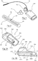
- FIGS. 3A to 7B various embodiments of a device or a system for fixing a temperature sensor according to the invention, intended to be placed in the ear canal of an animal.
- a fixing system 30 comprising a "glass tag” 20 as illustrated in FIG. figure 2 (Or more generally a temperature sensor and means for transmitting at least one temperature value), and a device for fixing a temperature sensor.
- a fixing device comprises a first portion 31 intended to bear on a first zone of the ear canal, defining at least one housing adapted to receive the "glass tag”, and a second portion 32 forming a spring, intended to bear on a second area of the auditory canal, the first and second areas of the auditory canal being substantially diametrically opposed.
- the first portion 31 defines a substantially cylindrical housing 311 whose height coincides with the first zone of the auditory canal, when the system 30 is placed inside thereof.
- An inlet orifice 3111 of the temperature sensor located on a first base of the cylindrical housing 311, allows the insertion of the "glass tag” 20 in this housing 311.
- an air exhaust port 3112 near a second base of the cylindrical housing 311.
- the second spring portion 32 is in the form of an ogival-shaped sheath, at least partially enveloping the first portion 31.
- such a sleeve has a longitudinal axis AA 'substantially parallel to a longitudinal axis BB' of the housing 311.
- the sleeve and the first portion are merged on a portion 321 intended to bear on the first zone of the auditory canal , at the height of housing 311.
- the first end 322 of the sleeve in the direction of introduction of the system into the auditory canal, has a rounded shape, so as to facilitate the insertion of the system 30 in the ear canal of the animal.
- the sheath In order to form a spring, the sheath has a flexible portion 326 intended to bear on the second zone of the auditory canal. Such a flexible portion 326 may be compressed upon insertion of the system into the animal's ear canal, and then released to seek to return to its original shape to maintain the system in the animal's ear canal. .
- the sheath is for example made of flexible plastic material, such as polyurethane.
- the first portion 31 may also be made of polyurethane, in order to facilitate the forced insertion of the "glass tag" into the housing 311.
- the sheath has at least one air inlet port 327 and at least one air outlet port 328 located on either side of the flexible portion 326 intended to bear on the second duct zone. auditory, so as not to alter the hearing ability of the animal, when the system is placed in the ear canal of the animal.
- a fastening system 40 comprising a "glass tag” 20 as illustrated in FIG. figure 2 (Or more generally a temperature sensor and means for transmitting at least one temperature value), and a device for fixing a temperature sensor.
- Such a fixing device comprises a first portion 41 intended to bear on a first zone of the auditory canal, defining at least one housing adapted to receive the "glasstag" 20, and a second portion 42 forming a spring intended to bear on a second zone of the auditory canal, the first and second zones of the auditory canal being substantially diametrically opposed.
- the first portion 41 is a helically shaped element.
- This helical element defines a substantially cylindrical housing 411 whose height coincides with the first zone of the auditory canal, when the system 40 is placed inside thereof.
- a 4111 input port of the temperature sensor located on a first base of the substantially cylindrical housing 411, allows the insertion of the "glass tag” 20 in this housing 411.
- a plurality of orifices 4112 d exhaust air near a second base of the substantially cylindrical housing 411, allowing the escape of air during the insertion of the "glass tag” in the housing 411.
- the second portion 42 forming a spring is in the form of a spring blade, connected to the helical element.
- This leaf spring allows easy insertion of the system 40 in the ear canal, when in its compression position and keeps the system 40 in the ear canal when it tends to return to its original shape.
- the leaf spring and the helical element can be formed in one piece, from a metal or plastic rod that is wound to form the first portion 41, and bend to form the second portion 42 .
- a fastening system 50 comprising a "glass tag” 20 as illustrated in FIG. figure 2 (Or more generally a temperature sensor and means for transmitting at least one temperature value), and a device for fixing a temperature sensor.
- Such a fixing device comprises a first portion 51 defining a housing adapted to receive the "glass tag" 20, and a second portion 52 intended to bear on at least two areas of the auditory canal, for example three zones, located substantially equal. distances in the auditory canal.
- the first portion 51 is a helically shaped element, defining a substantially cylindrical housing 511.
- An inlet 5111 of the temperature sensor inlet located on a first base of the substantially cylindrical housing 511, allows the insertion of the "glass tag” 20 in this housing 511.
- a plurality of orifices 5112 exhaust air near a second base of the substantially cylindrical housing 511, allowing the escape of air during the insertion of the "glass tag In dwelling 511.
- the second portion 52 forming a spring is in the form of a plurality of spring blades, for example three blades, connected to the helical element. These spring blades allow easy insertion of the system 50 into the auditory canal, when they are located in their compression position, and keep the system 50 in the ear canal when they tend to return to their original shape.
- the helical element is formed of three helicoids.
- a spring blade and a helicoid can then be formed in one piece, from a metal rod or plastic that is just wound to form the helicoid, and bend to form the leaf spring.
- the three sets "leaf spring / helicoid" are then assembled to close the housing 511.
- FIG. figure 2 Or more generally a temperature sensor and means for transmitting at least one temperature value, and a device for fixing a temperature sensor.
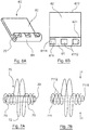
- Such a fixing device comprises a first portion 61 intended to bear on a first zone of the auditory canal, defining a housing adapted to receive the "glass tag" 20, and a second portion 62 intended to bear on at least a second zone of the auditory canal.
- the first portion 61 defines a substantially cylindrical housing 611 whose height coincides with the first zone of the auditory canal, when the system 60 is placed inside thereof.
- An inlet 6111 of the temperature sensor inlet located on a first base of the cylindrical housing 611, allows the insertion of the "glass tag” 20 in this housing 611.
- the second portion 62 forming a spring comprises a flexible plate, for example of substantially rectangular shape, connected by one of its sides 621 to the first portion 61.
- such a plate is made of flexible plastic with memory effect, or is a metal blade overmolded with polyurethane.
- the first portion 61 may also be made of polyurethane, in order to facilitate the forced insertion of the "glass tag" into the housing 611.
- the flexible plate In its compression position, the flexible plate is at least partially wound around the first portion 61, facilitating the insertion of the system 60 into the auditory canal. In the holding position, the flexible plate is at least partially unrolled. In this way, the fixation device can be supported on a first zone of the auditory canal at the level of the first portion 61, and on a second area of the ear canal at the side 622 opposite the side 621 connected to the first portion 61.
- a fastening system 70 comprising a "glass tag” 20 as illustrated in FIG. figure 2 (Or more generally a temperature sensor and means for transmitting at least one temperature value), and a device for fixing a temperature sensor.
- a fixing device comprises a first portion 71 defining at least one housing adapted to receive the "glass tag” 20, and a second portion 72 forming a spring, intended to bear on at least two areas of the auditory canal, substantially diametrically opposed.
- the first portion 71 and second portion 72 comprise a helical element, formed of at least one turn of a first diameter, defining a substantially cylindrical housing 711, and at least one turn of a second diameter, forming a spring, the second diameter being greater than the first diameter.
- An inlet 7111 of the temperature sensor inlet located on a first base of the substantially cylindrical housing 711, allows the insertion of the "glass tag” 20 into this housing 711.
- a plurality of orifices 7112 air exhaust near a second base of the substantially cylindrical housing 711.
- the first portion 71 is formed of at least one turn of a first diameter, connected to the second portion 72 formed of at least one turn of a second diameter, greater than the first diameter.
- the turns of the second spring portion 72 may be compressed in the direction illustrated by the arrows C in the compression position, allowing easy insertion of the system 70 into the ear canal. These turns of the second portion 72 keep the system 70 in the ear canal when they tend to return to their original shape.
- the helicoidal element formed of the turns of first diameter and second diameter may be formed in one piece, from a metal or plastic rod that is wound up according to the first diameter to form the first portion 71, and wind up to the second diameter to form the second portion 72.
- the temperature sensor or sensors, the means for transmitting at least one temperature reading, and possibly the electronic means of identification were inserted in a "glass tag".
- the temperature sensor or sensors, the means for transmitting at least one temperature reading, and possibly the electronic means of identification can take any other form.
- the shape of the housing of the first portion of the fixing device must be adapted to receive at least one or more temperature sensors and the transmission means of at least one temperature reading.
- the fixing device may provide a marking surface, for example, on the flexible plate, on the sheath, on the spring blade, on the helical elements, etc.
- visual means for identifying the animal may also be added to the fixing device, instead of or in addition to electronic identification means.
- Such visual and / or electronic identification means carry an identifier of the animal (identification number for example). This marking can be done by any known means (printing, laser engraving, inkjet, etc.).
- the fixation device of the fixation system can also be placed in the compression position in an injector, such as a syringe, and released into the ear canal.
- the second portion then seeks to return to its original form, which allows to permanently fix the system in the auditory canal.
- the fixation system can also be forcibly inserted into the ear canal.
- the total height of the fixation systems 30, 40, 50, 60 and 70, before placement in the auditory canal is at least equal to the diameter of the auditory canal of the animal concerned, so that ensure proper maintenance of the system in the ear canal and avoid unintentional extraction.
- the dimensions of the fixing device are adapted to the dimensions of the auditory canal of the animal concerned, and are therefore variable from one animal category to another. For example, it is considered that the diameter of the auditory canal of cattle is of the order of 8 mm.
- the diameter of the fixing device, in the initial state, may be of the order of 9 mm.
- the second spring portion in the compression position, the second spring portion must be compressed to reduce the diameter / height of the fastener to a dimension less than 8 mm, and in the holding position, the second portion tends to return to its shape. of origin, and is blocked by the walls of the auditory canal.
- the fixation device may be equipped with withdrawal means, such as for example a string, a notch adapted to cooperate with a specific tool, etc.
Landscapes
- Health & Medical Sciences (AREA)
- Life Sciences & Earth Sciences (AREA)
- Veterinary Medicine (AREA)
- Engineering & Computer Science (AREA)
- Wood Science & Technology (AREA)
- Zoology (AREA)
- Animal Behavior & Ethology (AREA)
- General Health & Medical Sciences (AREA)
- Public Health (AREA)
- Measuring And Recording Apparatus For Diagnosis (AREA)
- Measuring Temperature Or Quantity Of Heat (AREA)
- Housing For Livestock And Birds (AREA)
Claims (10)
- Befestigungsvorrichtung für mindestens einen Temperaturfühler an einem Tier, vorgesehen, in den Gehörgang eines Tieres gesetzt zu werden,
umfassend- einen ersten Teil (41, 51), der mindestens einen Sitz (411, 511) umfasst, geeignet mindestens einen Temperaturfühler und Übertragungseinrichtungen für mindestens einen Temperaturwert aufzunehmen, und- einen zweiten Teil (42, 52), der eine Feder bildet,wobei der erste Teil und/oder der zweite Teil ausgelegt sind, sich an mindestens zwei verschiedenen Bereichen des Gehörgangs abzustützen,
dadurch gekennzeichnet, dass der zweite Teil (42, 52) mindestens ein Federblatt umfasst, und dass der erste Teil (41, 51) ein mit dem mindestens einen Federblatt verbundenes schneckenförmiges Element ist. - Vorrichtung nach Anspruch 1, dadurch gekennzeichnet, dass der zweite Teil (42, 52) ausgelegt ist, mindestens zwei Stellungen einzunehmen, darunter eine Zusammendrückstellung, in der der zweite Teil so verformt ist, dass er das Einsetzen der Vorrichtung in den Gehörgang zulässt, und eine Haltestellung, in der der zweite Teil deutlich seine ursprüngliche Form wieder einnimmt, um die Vorrichtung mit dem Gehörgang verbunden zu halten.
- Vorrichtung nach einem beliebigen der Ansprüche 1 bis 2, dadurch gekennzeichnet, dass der Sitz eine Eingangsöffnung (4111, 5111) des Temperaturfühlers und mindestens eine Luftaustrittsöffnung (4112, 5112) umfasst.
- Vorrichtung nach einem beliebigen der Ansprüche 1 bis 3, dadurch gekennzeichnet, dass der erste Teil (41) ausgelegt ist, sich an einem ersten Bereich des Gehörgangs abzustützen, und dass der zweite Teil (42) ausgelegt ist, sich an einem zweiten Bereich des Gehörgangs abzustützen.
- Vorrichtung nach Anspruch 4, dadurch gekennzeichnet, dass der erste Teil einen zylindrischen Sitz (411) umschließt, bei dem eine Höhe ausgelegt ist, mit dem ersten Bereich des Gehörgangs übereinzustimmen, wenn die Vorrichtung in den Gehörgang gesetzt ist.
- Vorrichtung nach einem beliebigen der Ansprüche 1 bis 5, dadurch gekennzeichnet, dass sie auch mindestens einen Sitz umfasst, geeignet, elektronische Identifikationseinrichtungen für das Tier aufzunehmen.
- Vorrichtung nach einem beliebigen der Ansprüche 1 bis 6, dadurch gekennzeichnet, dass sie eine Markierungsfläche für eine Kennung des Tieres umfasst.
- Vorrichtung nach einem beliebigen der Ansprüche 1 bis 7, dadurch gekennzeichnet, dass sie Entnahmeeinrichtungen für die Vorrichtung umfasst.
- Befestigungssystem für mindestens einen Temperaturfühler an einem Tier, vorgesehen, in den Gehörgang eines Tieres gesetzt zu werden,
dadurch gekennzeichnet, dass es umfasst:- eine Befestigungsvorrichtung nach einem beliebigen der Ansprüche 1 bis 8,- mindestens einen Temperaturfühler (21) und Übertragungseinrichtungen (22) für mindestens einen Temperaturwert, eingesetzt in einen Sitz der Befestigungsvorrichtung. - Befestigungssystem nach Anspruch 9, dadurch gekennzeichnet, dass es auch elektronische Identifikationseinrichtungen (23) für das Tier umfasst, die in den Sitz oder in einen anderen Sitz der Befestigungsvorrichtung eingesetzt sind.
Applications Claiming Priority (2)
| Application Number | Priority Date | Filing Date | Title |
|---|---|---|---|
| FR1457455A FR3024353A1 (fr) | 2014-07-31 | 2014-07-31 | Dispositif de fixation d'un capteur de temperature destine a etre place dans le conduit auditif d'un animal. |
| PCT/EP2015/065153 WO2016015948A1 (fr) | 2014-07-31 | 2015-07-02 | Dispositif de fixation d'un capteur de température destiné à être placé dans le conduit auditif d'un animal |
Publications (2)
| Publication Number | Publication Date |
|---|---|
| EP3174496A1 EP3174496A1 (de) | 2017-06-07 |
| EP3174496B1 true EP3174496B1 (de) | 2018-04-11 |
Family
ID=51932396
Family Applications (1)
| Application Number | Title | Priority Date | Filing Date |
|---|---|---|---|
| EP15734650.3A Not-in-force EP3174496B1 (de) | 2014-07-31 | 2015-07-02 | Vorrichtung zur befestigung eines temperatursensors zur positionierung in den gehörgang eines tieres |
Country Status (8)
| Country | Link |
|---|---|
| US (1) | US20170224456A1 (de) |
| EP (1) | EP3174496B1 (de) |
| AU (1) | AU2015295707A1 (de) |
| BR (1) | BR112017001827A2 (de) |
| CA (1) | CA2953269A1 (de) |
| FR (1) | FR3024353A1 (de) |
| MX (1) | MX2017000211A (de) |
| WO (1) | WO2016015948A1 (de) |
Families Citing this family (4)
| Publication number | Priority date | Publication date | Assignee | Title |
|---|---|---|---|---|
| US9848577B1 (en) * | 2017-05-15 | 2017-12-26 | Herddogg, Inc. | Animal tag system |
| US10130265B1 (en) | 2017-05-15 | 2018-11-20 | Herddogg, Inc. | Animal tag system |
| WO2021089541A1 (en) * | 2019-11-04 | 2021-05-14 | Moovement Holding B.V. | System and apparatus for the monitoring of livestock and the like |
| CN112798123B (zh) * | 2021-01-07 | 2021-11-23 | 郑州铁路职业技术学院 | 一种蓝牙无线体温监测装置 |
Family Cites Families (2)
| Publication number | Priority date | Publication date | Assignee | Title |
|---|---|---|---|---|
| FR2233971B1 (de) * | 1973-06-21 | 1976-09-17 | Jac Inc | |
| KR101940746B1 (ko) * | 2012-11-26 | 2019-01-22 | 한국전자통신연구원 | 이어 플러그 통신 장치 |
-
2014
- 2014-07-31 FR FR1457455A patent/FR3024353A1/fr active Pending
-
2015
- 2015-07-02 WO PCT/EP2015/065153 patent/WO2016015948A1/fr not_active Ceased
- 2015-07-02 CA CA2953269A patent/CA2953269A1/en not_active Abandoned
- 2015-07-02 AU AU2015295707A patent/AU2015295707A1/en not_active Abandoned
- 2015-07-02 MX MX2017000211A patent/MX2017000211A/es unknown
- 2015-07-02 EP EP15734650.3A patent/EP3174496B1/de not_active Not-in-force
- 2015-07-02 BR BR112017001827A patent/BR112017001827A2/pt not_active IP Right Cessation
- 2015-07-02 US US15/500,825 patent/US20170224456A1/en not_active Abandoned
Also Published As
| Publication number | Publication date |
|---|---|
| BR112017001827A2 (pt) | 2018-06-19 |
| US20170224456A1 (en) | 2017-08-10 |
| MX2017000211A (es) | 2017-07-17 |
| CA2953269A1 (en) | 2016-02-04 |
| WO2016015948A1 (fr) | 2016-02-04 |
| EP3174496A1 (de) | 2017-06-07 |
| AU2015295707A1 (en) | 2017-01-19 |
| FR3024353A1 (fr) | 2016-02-05 |
Similar Documents
| Publication | Publication Date | Title |
|---|---|---|
| AU2014386957B2 (en) | Metal ear tag with overmoulded cover for transponder housing, and method of assembling the same | |
| US7533482B2 (en) | Metal ear tag with electronic identification device | |
| US9038293B2 (en) | Resinated device for identifying an animal, and corresponding method for manufacturing | |
| FR3024353A1 (fr) | Dispositif de fixation d'un capteur de temperature destine a etre place dans le conduit auditif d'un animal. | |
| FR2823065A1 (fr) | Etiquette auriculaire de marquage des animaux avec systeme de prelevement de matiere organique | |
| WO2012019956A1 (fr) | Dispositif d'identification d'un animal et dispositif de fabrication correspondant | |
| CA3002005C (fr) | Dispositif pour le suivi individualise de l'indice de consommation de volailles et installation comportant ledit dispositif | |
| EP2229049B1 (de) | Heilungsfördernder markierungsohrring | |
| WO2001056373A1 (fr) | Bouton d'identification | |
| WO2007147973A1 (fr) | Etiquette auriculaire d’identification pour animal | |
| EP2596700A2 (de) | Tieridentifizierungsvorrichtung | |
| EP3174386B1 (de) | Tieridentifizierungssystem mit einer tieridentifizierungsvorrichtung und einem probeelement | |
| FR2849744A1 (fr) | Bracelet de chasse equipe de moyens electroniques pour attester de l'irreversibilite de sa fermeture | |
| FR2831389A1 (fr) | Perfectionnement pour dispositif d'identification | |
| WO2014083185A1 (fr) | Trappe pour terminal | |
| EP2028929B1 (de) | Ohrmarke zur identifizierung eines tieres | |
| FR3053527A1 (fr) | Procede de marquage inviolable et tracable d'un assemblage de deux elements | |
| EP3692787B1 (de) | Aufnahmeteil einer identifizierungsvorrichtung für tiere, die ein blockerierlement des einsteckteils in den aufnahmeteil umfasst, und entsprechende identifizierungsvorrichtung für tiere | |
| FR2982056A1 (fr) | Appareil de programmation pour puce rfid d'identification. | |
| WO2010072689A2 (fr) | Partie male d'une marque pour le marquage d'un animal et ensemble de stockage d'au moins deux parties males correspondant | |
| FR2909835A1 (fr) | Etiquette auriculaire d'identification pour animal. | |
| BE1021729B1 (nl) | Identificatiekit voor het identificeren van een levend wezen | |
| Levallois | Contraintes particulières applicables pour la conception des systèmes de vide de SPIRAL2. | |
| Regad et al. | Evolution of the concept of the legal personality–Proposal emerged from the trilogy on the legal personality of the animal | |
| FR3026527A1 (fr) | Bague connectee. |
Legal Events
| Date | Code | Title | Description |
|---|---|---|---|
| 17P | Request for examination filed |
Effective date: 20161216 |
|
| AK | Designated contracting states |
Kind code of ref document: A1 Designated state(s): AL AT BE BG CH CY CZ DE DK EE ES FI FR GB GR HR HU IE IS IT LI LT LU LV MC MK MT NL NO PL PT RO RS SE SI SK SM TR |
|
| AX | Request for extension of the european patent |
Extension state: BA ME |
|
| PUAI | Public reference made under article 153(3) epc to a published international application that has entered the european phase |
Free format text: ORIGINAL CODE: 0009012 |
|
| RIN1 | Information on inventor provided before grant (corrected) |
Inventor name: DE MEULEMEESTER, JOHAN Inventor name: DECALUWE, JOHAN Inventor name: HILPERT, JEAN-JACQUES |
|
| DAV | Request for validation of the european patent (deleted) | ||
| DAX | Request for extension of the european patent (deleted) | ||
| GRAP | Despatch of communication of intention to grant a patent |
Free format text: ORIGINAL CODE: EPIDOSNIGR1 |
|
| INTG | Intention to grant announced |
Effective date: 20171117 |
|
| RIN1 | Information on inventor provided before grant (corrected) |
Inventor name: HILPERT, JEAN-JACQUES Inventor name: DECALUWE, JOHAN Inventor name: DE MEULEMEESTER, JOHAN |
|
| GRAS | Grant fee paid |
Free format text: ORIGINAL CODE: EPIDOSNIGR3 |
|
| GRAA | (expected) grant |
Free format text: ORIGINAL CODE: 0009210 |
|
| AK | Designated contracting states |
Kind code of ref document: B1 Designated state(s): AL AT BE BG CH CY CZ DE DK EE ES FI FR GB GR HR HU IE IS IT LI LT LU LV MC MK MT NL NO PL PT RO RS SE SI SK SM TR |
|
| REG | Reference to a national code |
Ref country code: GB Ref legal event code: FG4D Free format text: NOT ENGLISH |
|
| REG | Reference to a national code |
Ref country code: CH Ref legal event code: EP |
|
| REG | Reference to a national code |
Ref country code: AT Ref legal event code: REF Ref document number: 987180 Country of ref document: AT Kind code of ref document: T Effective date: 20180415 |
|
| REG | Reference to a national code |
Ref country code: IE Ref legal event code: FG4D Free format text: LANGUAGE OF EP DOCUMENT: FRENCH |
|
| REG | Reference to a national code |
Ref country code: DE Ref legal event code: R096 Ref document number: 602015009930 Country of ref document: DE |
|
| REG | Reference to a national code |
Ref country code: NL Ref legal event code: MP Effective date: 20180411 |
|
| REG | Reference to a national code |
Ref country code: LT Ref legal event code: MG4D |
|
| PG25 | Lapsed in a contracting state [announced via postgrant information from national office to epo] |
Ref country code: NL Free format text: LAPSE BECAUSE OF FAILURE TO SUBMIT A TRANSLATION OF THE DESCRIPTION OR TO PAY THE FEE WITHIN THE PRESCRIBED TIME-LIMIT Effective date: 20180411 |
|
| PG25 | Lapsed in a contracting state [announced via postgrant information from national office to epo] |
Ref country code: NO Free format text: LAPSE BECAUSE OF FAILURE TO SUBMIT A TRANSLATION OF THE DESCRIPTION OR TO PAY THE FEE WITHIN THE PRESCRIBED TIME-LIMIT Effective date: 20180711 Ref country code: FI Free format text: LAPSE BECAUSE OF FAILURE TO SUBMIT A TRANSLATION OF THE DESCRIPTION OR TO PAY THE FEE WITHIN THE PRESCRIBED TIME-LIMIT Effective date: 20180411 Ref country code: BG Free format text: LAPSE BECAUSE OF FAILURE TO SUBMIT A TRANSLATION OF THE DESCRIPTION OR TO PAY THE FEE WITHIN THE PRESCRIBED TIME-LIMIT Effective date: 20180711 Ref country code: ES Free format text: LAPSE BECAUSE OF FAILURE TO SUBMIT A TRANSLATION OF THE DESCRIPTION OR TO PAY THE FEE WITHIN THE PRESCRIBED TIME-LIMIT Effective date: 20180411 Ref country code: AL Free format text: LAPSE BECAUSE OF FAILURE TO SUBMIT A TRANSLATION OF THE DESCRIPTION OR TO PAY THE FEE WITHIN THE PRESCRIBED TIME-LIMIT Effective date: 20180411 Ref country code: SE Free format text: LAPSE BECAUSE OF FAILURE TO SUBMIT A TRANSLATION OF THE DESCRIPTION OR TO PAY THE FEE WITHIN THE PRESCRIBED TIME-LIMIT Effective date: 20180411 Ref country code: LT Free format text: LAPSE BECAUSE OF FAILURE TO SUBMIT A TRANSLATION OF THE DESCRIPTION OR TO PAY THE FEE WITHIN THE PRESCRIBED TIME-LIMIT Effective date: 20180411 Ref country code: PL Free format text: LAPSE BECAUSE OF FAILURE TO SUBMIT A TRANSLATION OF THE DESCRIPTION OR TO PAY THE FEE WITHIN THE PRESCRIBED TIME-LIMIT Effective date: 20180411 |
|
| PG25 | Lapsed in a contracting state [announced via postgrant information from national office to epo] |
Ref country code: LV Free format text: LAPSE BECAUSE OF FAILURE TO SUBMIT A TRANSLATION OF THE DESCRIPTION OR TO PAY THE FEE WITHIN THE PRESCRIBED TIME-LIMIT Effective date: 20180411 Ref country code: HR Free format text: LAPSE BECAUSE OF FAILURE TO SUBMIT A TRANSLATION OF THE DESCRIPTION OR TO PAY THE FEE WITHIN THE PRESCRIBED TIME-LIMIT Effective date: 20180411 Ref country code: GR Free format text: LAPSE BECAUSE OF FAILURE TO SUBMIT A TRANSLATION OF THE DESCRIPTION OR TO PAY THE FEE WITHIN THE PRESCRIBED TIME-LIMIT Effective date: 20180712 Ref country code: RS Free format text: LAPSE BECAUSE OF FAILURE TO SUBMIT A TRANSLATION OF THE DESCRIPTION OR TO PAY THE FEE WITHIN THE PRESCRIBED TIME-LIMIT Effective date: 20180411 |
|
| REG | Reference to a national code |
Ref country code: AT Ref legal event code: MK05 Ref document number: 987180 Country of ref document: AT Kind code of ref document: T Effective date: 20180411 |
|
| PG25 | Lapsed in a contracting state [announced via postgrant information from national office to epo] |
Ref country code: PT Free format text: LAPSE BECAUSE OF FAILURE TO SUBMIT A TRANSLATION OF THE DESCRIPTION OR TO PAY THE FEE WITHIN THE PRESCRIBED TIME-LIMIT Effective date: 20180813 |
|
| REG | Reference to a national code |
Ref country code: DE Ref legal event code: R097 Ref document number: 602015009930 Country of ref document: DE |
|
| PG25 | Lapsed in a contracting state [announced via postgrant information from national office to epo] |
Ref country code: DK Free format text: LAPSE BECAUSE OF FAILURE TO SUBMIT A TRANSLATION OF THE DESCRIPTION OR TO PAY THE FEE WITHIN THE PRESCRIBED TIME-LIMIT Effective date: 20180411 Ref country code: EE Free format text: LAPSE BECAUSE OF FAILURE TO SUBMIT A TRANSLATION OF THE DESCRIPTION OR TO PAY THE FEE WITHIN THE PRESCRIBED TIME-LIMIT Effective date: 20180411 Ref country code: AT Free format text: LAPSE BECAUSE OF FAILURE TO SUBMIT A TRANSLATION OF THE DESCRIPTION OR TO PAY THE FEE WITHIN THE PRESCRIBED TIME-LIMIT Effective date: 20180411 Ref country code: RO Free format text: LAPSE BECAUSE OF FAILURE TO SUBMIT A TRANSLATION OF THE DESCRIPTION OR TO PAY THE FEE WITHIN THE PRESCRIBED TIME-LIMIT Effective date: 20180411 Ref country code: CZ Free format text: LAPSE BECAUSE OF FAILURE TO SUBMIT A TRANSLATION OF THE DESCRIPTION OR TO PAY THE FEE WITHIN THE PRESCRIBED TIME-LIMIT Effective date: 20180411 Ref country code: SK Free format text: LAPSE BECAUSE OF FAILURE TO SUBMIT A TRANSLATION OF THE DESCRIPTION OR TO PAY THE FEE WITHIN THE PRESCRIBED TIME-LIMIT Effective date: 20180411 |
|
| REG | Reference to a national code |
Ref country code: DE Ref legal event code: R119 Ref document number: 602015009930 Country of ref document: DE |
|
| PLBE | No opposition filed within time limit |
Free format text: ORIGINAL CODE: 0009261 |
|
| STAA | Information on the status of an ep patent application or granted ep patent |
Free format text: STATUS: NO OPPOSITION FILED WITHIN TIME LIMIT |
|
| PG25 | Lapsed in a contracting state [announced via postgrant information from national office to epo] |
Ref country code: SM Free format text: LAPSE BECAUSE OF FAILURE TO SUBMIT A TRANSLATION OF THE DESCRIPTION OR TO PAY THE FEE WITHIN THE PRESCRIBED TIME-LIMIT Effective date: 20180411 Ref country code: IT Free format text: LAPSE BECAUSE OF FAILURE TO SUBMIT A TRANSLATION OF THE DESCRIPTION OR TO PAY THE FEE WITHIN THE PRESCRIBED TIME-LIMIT Effective date: 20180411 |
|
| REG | Reference to a national code |
Ref country code: CH Ref legal event code: PL |
|
| 26N | No opposition filed |
Effective date: 20190114 |
|
| PG25 | Lapsed in a contracting state [announced via postgrant information from national office to epo] |
Ref country code: LU Free format text: LAPSE BECAUSE OF NON-PAYMENT OF DUE FEES Effective date: 20180702 Ref country code: MC Free format text: LAPSE BECAUSE OF FAILURE TO SUBMIT A TRANSLATION OF THE DESCRIPTION OR TO PAY THE FEE WITHIN THE PRESCRIBED TIME-LIMIT Effective date: 20180411 |
|
| REG | Reference to a national code |
Ref country code: BE Ref legal event code: MM Effective date: 20180731 |
|
| REG | Reference to a national code |
Ref country code: IE Ref legal event code: MM4A |
|
| PG25 | Lapsed in a contracting state [announced via postgrant information from national office to epo] |
Ref country code: DE Free format text: LAPSE BECAUSE OF NON-PAYMENT OF DUE FEES Effective date: 20190201 Ref country code: LI Free format text: LAPSE BECAUSE OF NON-PAYMENT OF DUE FEES Effective date: 20180731 Ref country code: CH Free format text: LAPSE BECAUSE OF NON-PAYMENT OF DUE FEES Effective date: 20180731 Ref country code: FR Free format text: LAPSE BECAUSE OF NON-PAYMENT OF DUE FEES Effective date: 20180731 Ref country code: IE Free format text: LAPSE BECAUSE OF NON-PAYMENT OF DUE FEES Effective date: 20180702 |
|
| PG25 | Lapsed in a contracting state [announced via postgrant information from national office to epo] |
Ref country code: BE Free format text: LAPSE BECAUSE OF NON-PAYMENT OF DUE FEES Effective date: 20180731 Ref country code: SI Free format text: LAPSE BECAUSE OF FAILURE TO SUBMIT A TRANSLATION OF THE DESCRIPTION OR TO PAY THE FEE WITHIN THE PRESCRIBED TIME-LIMIT Effective date: 20180411 |
|
| PG25 | Lapsed in a contracting state [announced via postgrant information from national office to epo] |
Ref country code: MT Free format text: LAPSE BECAUSE OF FAILURE TO SUBMIT A TRANSLATION OF THE DESCRIPTION OR TO PAY THE FEE WITHIN THE PRESCRIBED TIME-LIMIT Effective date: 20180411 |
|
| GBPC | Gb: european patent ceased through non-payment of renewal fee |
Effective date: 20190702 |
|
| PG25 | Lapsed in a contracting state [announced via postgrant information from national office to epo] |
Ref country code: TR Free format text: LAPSE BECAUSE OF FAILURE TO SUBMIT A TRANSLATION OF THE DESCRIPTION OR TO PAY THE FEE WITHIN THE PRESCRIBED TIME-LIMIT Effective date: 20180411 |
|
| PG25 | Lapsed in a contracting state [announced via postgrant information from national office to epo] |
Ref country code: GB Free format text: LAPSE BECAUSE OF NON-PAYMENT OF DUE FEES Effective date: 20190702 |
|
| PG25 | Lapsed in a contracting state [announced via postgrant information from national office to epo] |
Ref country code: MK Free format text: LAPSE BECAUSE OF NON-PAYMENT OF DUE FEES Effective date: 20180411 Ref country code: CY Free format text: LAPSE BECAUSE OF FAILURE TO SUBMIT A TRANSLATION OF THE DESCRIPTION OR TO PAY THE FEE WITHIN THE PRESCRIBED TIME-LIMIT Effective date: 20180411 Ref country code: HU Free format text: LAPSE BECAUSE OF FAILURE TO SUBMIT A TRANSLATION OF THE DESCRIPTION OR TO PAY THE FEE WITHIN THE PRESCRIBED TIME-LIMIT; INVALID AB INITIO Effective date: 20150702 |
|
| PG25 | Lapsed in a contracting state [announced via postgrant information from national office to epo] |
Ref country code: IS Free format text: LAPSE BECAUSE OF FAILURE TO SUBMIT A TRANSLATION OF THE DESCRIPTION OR TO PAY THE FEE WITHIN THE PRESCRIBED TIME-LIMIT Effective date: 20180811 |