EP3174133A1 - Bus bar line and battery module therewith - Google Patents
Bus bar line and battery module therewith Download PDFInfo
- Publication number
- EP3174133A1 EP3174133A1 EP16186761.9A EP16186761A EP3174133A1 EP 3174133 A1 EP3174133 A1 EP 3174133A1 EP 16186761 A EP16186761 A EP 16186761A EP 3174133 A1 EP3174133 A1 EP 3174133A1
- Authority
- EP
- European Patent Office
- Prior art keywords
- ffc
- container
- bus bar
- electric cells
- bus bars
- Prior art date
- Legal status (The legal status is an assumption and is not a legal conclusion. Google has not performed a legal analysis and makes no representation as to the accuracy of the status listed.)
- Granted
Links
Images


Classifications
-
- H—ELECTRICITY
- H01—ELECTRIC ELEMENTS
- H01M—PROCESSES OR MEANS, e.g. BATTERIES, FOR THE DIRECT CONVERSION OF CHEMICAL ENERGY INTO ELECTRICAL ENERGY
- H01M10/00—Secondary cells; Manufacture thereof
- H01M10/42—Methods or arrangements for servicing or maintenance of secondary cells or secondary half-cells
- H01M10/48—Accumulators combined with arrangements for measuring, testing or indicating the condition of cells, e.g. the level or density of the electrolyte
- H01M10/482—Accumulators combined with arrangements for measuring, testing or indicating the condition of cells, e.g. the level or density of the electrolyte for several batteries or cells simultaneously or sequentially
-
- H—ELECTRICITY
- H01—ELECTRIC ELEMENTS
- H01M—PROCESSES OR MEANS, e.g. BATTERIES, FOR THE DIRECT CONVERSION OF CHEMICAL ENERGY INTO ELECTRICAL ENERGY
- H01M10/00—Secondary cells; Manufacture thereof
- H01M10/42—Methods or arrangements for servicing or maintenance of secondary cells or secondary half-cells
- H01M10/425—Structural combination with electronic components, e.g. electronic circuits integrated to the outside of the casing
-
- H—ELECTRICITY
- H01—ELECTRIC ELEMENTS
- H01M—PROCESSES OR MEANS, e.g. BATTERIES, FOR THE DIRECT CONVERSION OF CHEMICAL ENERGY INTO ELECTRICAL ENERGY
- H01M50/00—Constructional details or processes of manufacture of the non-active parts of electrochemical cells other than fuel cells, e.g. hybrid cells
- H01M50/20—Mountings; Secondary casings or frames; Racks, modules or packs; Suspension devices; Shock absorbers; Transport or carrying devices; Holders
- H01M50/204—Racks, modules or packs for multiple batteries or multiple cells
- H01M50/207—Racks, modules or packs for multiple batteries or multiple cells characterised by their shape
- H01M50/209—Racks, modules or packs for multiple batteries or multiple cells characterised by their shape adapted for prismatic or rectangular cells
-
- H—ELECTRICITY
- H01—ELECTRIC ELEMENTS
- H01M—PROCESSES OR MEANS, e.g. BATTERIES, FOR THE DIRECT CONVERSION OF CHEMICAL ENERGY INTO ELECTRICAL ENERGY
- H01M50/00—Constructional details or processes of manufacture of the non-active parts of electrochemical cells other than fuel cells, e.g. hybrid cells
- H01M50/20—Mountings; Secondary casings or frames; Racks, modules or packs; Suspension devices; Shock absorbers; Transport or carrying devices; Holders
- H01M50/289—Mountings; Secondary casings or frames; Racks, modules or packs; Suspension devices; Shock absorbers; Transport or carrying devices; Holders characterised by spacing elements or positioning means within frames, racks or packs
- H01M50/293—Mountings; Secondary casings or frames; Racks, modules or packs; Suspension devices; Shock absorbers; Transport or carrying devices; Holders characterised by spacing elements or positioning means within frames, racks or packs characterised by the material
-
- H—ELECTRICITY
- H01—ELECTRIC ELEMENTS
- H01M—PROCESSES OR MEANS, e.g. BATTERIES, FOR THE DIRECT CONVERSION OF CHEMICAL ENERGY INTO ELECTRICAL ENERGY
- H01M50/00—Constructional details or processes of manufacture of the non-active parts of electrochemical cells other than fuel cells, e.g. hybrid cells
- H01M50/20—Mountings; Secondary casings or frames; Racks, modules or packs; Suspension devices; Shock absorbers; Transport or carrying devices; Holders
- H01M50/298—Mountings; Secondary casings or frames; Racks, modules or packs; Suspension devices; Shock absorbers; Transport or carrying devices; Holders characterised by the wiring of battery packs
-
- H—ELECTRICITY
- H01—ELECTRIC ELEMENTS
- H01M—PROCESSES OR MEANS, e.g. BATTERIES, FOR THE DIRECT CONVERSION OF CHEMICAL ENERGY INTO ELECTRICAL ENERGY
- H01M50/00—Constructional details or processes of manufacture of the non-active parts of electrochemical cells other than fuel cells, e.g. hybrid cells
- H01M50/50—Current conducting connections for cells or batteries
- H01M50/502—Interconnectors for connecting terminals of adjacent batteries; Interconnectors for connecting cells outside a battery casing
- H01M50/503—Interconnectors for connecting terminals of adjacent batteries; Interconnectors for connecting cells outside a battery casing characterised by the shape of the interconnectors
-
- H—ELECTRICITY
- H01—ELECTRIC ELEMENTS
- H01M—PROCESSES OR MEANS, e.g. BATTERIES, FOR THE DIRECT CONVERSION OF CHEMICAL ENERGY INTO ELECTRICAL ENERGY
- H01M50/00—Constructional details or processes of manufacture of the non-active parts of electrochemical cells other than fuel cells, e.g. hybrid cells
- H01M50/50—Current conducting connections for cells or batteries
- H01M50/502—Interconnectors for connecting terminals of adjacent batteries; Interconnectors for connecting cells outside a battery casing
- H01M50/507—Interconnectors for connecting terminals of adjacent batteries; Interconnectors for connecting cells outside a battery casing comprising an arrangement of two or more busbars within a container structure, e.g. busbar modules
-
- H—ELECTRICITY
- H01—ELECTRIC ELEMENTS
- H01M—PROCESSES OR MEANS, e.g. BATTERIES, FOR THE DIRECT CONVERSION OF CHEMICAL ENERGY INTO ELECTRICAL ENERGY
- H01M50/00—Constructional details or processes of manufacture of the non-active parts of electrochemical cells other than fuel cells, e.g. hybrid cells
- H01M50/50—Current conducting connections for cells or batteries
- H01M50/569—Constructional details of current conducting connections for detecting conditions inside cells or batteries, e.g. details of voltage sensing terminals
-
- H—ELECTRICITY
- H01—ELECTRIC ELEMENTS
- H01M—PROCESSES OR MEANS, e.g. BATTERIES, FOR THE DIRECT CONVERSION OF CHEMICAL ENERGY INTO ELECTRICAL ENERGY
- H01M2200/00—Safety devices for primary or secondary batteries
- H01M2200/20—Pressure-sensitive devices
-
- H—ELECTRICITY
- H01—ELECTRIC ELEMENTS
- H01M—PROCESSES OR MEANS, e.g. BATTERIES, FOR THE DIRECT CONVERSION OF CHEMICAL ENERGY INTO ELECTRICAL ENERGY
- H01M50/00—Constructional details or processes of manufacture of the non-active parts of electrochemical cells other than fuel cells, e.g. hybrid cells
- H01M50/10—Primary casings; Jackets or wrappings
- H01M50/116—Primary casings; Jackets or wrappings characterised by the material
- H01M50/117—Inorganic material
- H01M50/119—Metals
-
- H—ELECTRICITY
- H01—ELECTRIC ELEMENTS
- H01R—ELECTRICALLY-CONDUCTIVE CONNECTIONS; STRUCTURAL ASSOCIATIONS OF A PLURALITY OF MUTUALLY-INSULATED ELECTRICAL CONNECTING ELEMENTS; COUPLING DEVICES; CURRENT COLLECTORS
- H01R12/00—Structural associations of a plurality of mutually-insulated electrical connecting elements, specially adapted for printed circuits, e.g. printed circuit boards [PCB], flat or ribbon cables, or like generally planar structures, e.g. terminal strips, terminal blocks; Coupling devices specially adapted for printed circuits, flat or ribbon cables, or like generally planar structures; Terminals specially adapted for contact with, or insertion into, printed circuits, flat or ribbon cables, or like generally planar structures
- H01R12/50—Fixed connections
- H01R12/59—Fixed connections for flexible printed circuits, flat or ribbon cables or like structures
- H01R12/592—Fixed connections for flexible printed circuits, flat or ribbon cables or like structures connections to contact elements
-
- H—ELECTRICITY
- H01—ELECTRIC ELEMENTS
- H01R—ELECTRICALLY-CONDUCTIVE CONNECTIONS; STRUCTURAL ASSOCIATIONS OF A PLURALITY OF MUTUALLY-INSULATED ELECTRICAL CONNECTING ELEMENTS; COUPLING DEVICES; CURRENT COLLECTORS
- H01R25/00—Coupling parts adapted for simultaneous co-operation with two or more identical counterparts, e.g. for distributing energy to two or more circuits
- H01R25/16—Rails or bus-bars provided with a plurality of discrete connecting locations for counterparts
-
- Y—GENERAL TAGGING OF NEW TECHNOLOGICAL DEVELOPMENTS; GENERAL TAGGING OF CROSS-SECTIONAL TECHNOLOGIES SPANNING OVER SEVERAL SECTIONS OF THE IPC; TECHNICAL SUBJECTS COVERED BY FORMER USPC CROSS-REFERENCE ART COLLECTIONS [XRACs] AND DIGESTS
- Y02—TECHNOLOGIES OR APPLICATIONS FOR MITIGATION OR ADAPTATION AGAINST CLIMATE CHANGE
- Y02E—REDUCTION OF GREENHOUSE GAS [GHG] EMISSIONS, RELATED TO ENERGY GENERATION, TRANSMISSION OR DISTRIBUTION
- Y02E60/00—Enabling technologies; Technologies with a potential or indirect contribution to GHG emissions mitigation
- Y02E60/10—Energy storage using batteries
Definitions
- This invention relates to a bus bar line and a battery module having such a bus bar line.
- Assembly of the battery module having the above structure requires the connecting members to connect the electrode terminals at plural positions, which thus necessitates a cumbersome operation to repeat the operations for connecting the electrode terminals with the connecting members.
- a use of a battery connecting plate in which, in accordance with the number of inter-terminal spaces between the electrode terminals to be connected, a plurality of connecting members disposed in a die is integrated into a resin by a method such as insert molding (e.g., see, JP 3990960 A ).
- the plurality of inter-terminal spaces between the electrode terminals of the electric cells adjacent to each other is collectively connectable simply by attaching the single battery connecting plate to the plurality of electrode terminals protruding from the plurality of electric cells, which enhances the operational efficiency.
- pitches between the electrode terminals of the adjacent electric cells may not become constant in the battery module in which the plurality of electric cells is juxtaposed.
- the electrode terminals and the connecting members of the battery connecting plate may be positionally misaligned, which can lead to reduction in the efficiency of the connecting operations of the battery connecting plate.
- the integrally-molded connecting plate described above may not be able to compensate the positional misalignment.
- the present invention was made in view of the foregoing circumstances. It is an object of the invention to provide a bus bar line in which non-constancy of pitches between adjacent electrode terminals is easily adjustable. A further object of the invention is to provide a battery module for such a bus bar line.
- bus bar line according to claim 1.
- battery module according to claim 5.
- a bus bar line according to the present invention ist to be disposed on a plurality of electric cells each having positive and negative electrode terminals, the plurality of electric cells are transversely juxtaposed.
- the bus bar line comprises a plurality of bus bars electrically connecting the electrode terminals of electric cells adjacent to each other; a first insulating resin portion including a first film made of an insulating resin, the first insulating resin portion connects the plurality of bus bars; and a projection disposing clearance is provided between the adjacent bus bars, wherein a projection of a separator is disposed in the projection disposing clearance.
- a battery module according to the present invention in which a plurality of electric cells each having positive and negative electrode terminals is transversely juxtaposed, includes: the bus bar line according to the first aspect of the invention, said bus bar line being disposed on the plurality of electric cells, wherein the electric cells include metal-made battery containers; and a resin-made separator is provided between the electric cells adjacent to each other, the separator having a projection projecting outward from an outer wall surface of the battery containers.
- the plurality of connecting members electrically connecting the electrode terminals is joined to one another by the flexible flat cable.
- the portions of the flexible flat cable to be disposed between the adjacent connecting members are provided with the folded members formed by folding the flexible flat cable at the folded lines extending in the direction crossing the longitudinal direction of the flexible flat cable. Therefore, according to the present invention, even when pitches between the adjacent electrode terminals of the electric cells in the battery module are not constant, or when the pitches between the adjacent electrode terminals are made non-constant due to shrinkage or expansion of the electric cells of the battery module in the direction in which the electric cells are juxtaposed, the non-constancy is compensated by the folded portions of the flexible flat cable. As a result, in the battery module according to the present invention, non-constancy of the pitches between the adjacent electrode terminals is easily adjustable.
- the battery module according to the present invention may include any one of the following arrangements.
- the battery module according to the present invention may further include a plurality of container members containing the connecting members, and the container members may be provided with a holder holding portions of the flexible flat cable other than the folded portions.
- the flexible flat cable may be twisted when the folded portions of the flexible flat cable elongated in accordance with the expansion of the electric cells return to their original positions in accordance with the contraction of the electric cells.
- the twisting of the flexible flat cable is prevented.
- the flexible flat cable may be a voltage detecting line measuring a voltage of the electric cells.
- the flexible flat cable not only joints the connecting members but also serves as the voltage detecting line for detecting the voltage of the electric cells. Therefore, no other voltage detecting line than the flexible flat cable is required to be separately connected to the battery module, and thus the number of components is reducible.
- the conductor of the flexible flat cable may be directly connected with the connecting members.
- the connection structure of the voltage detecting line saves space in the thickness direction of the terminal forming surface of the electric cells, and the connection structure of the voltage detecting line is downsized in the battery module.
- the flexible flat cable is connectable to the connecting members by a low-cost method such as resistance welding or ultrasonic welding, which also contributes to further cost reduction.
- the container members may be provided with a joint joining container members adjacent to each other, and the joint may include: a jointing projection projecting in a direction in which the plurality of electric cells is juxtaposed; and a jointing receiver receiving the jointing projection.
- the electric cells may include metal-made battery containers, and a resin-made separator may be provided between the electric cells adjacent to each other, the separator having a projection projecting outward from an outer wall surface of the battery containers.
- non-constancy of the pitches between the electrode terminals adjacent to each other is easily adjustable.
- FIGs. 1 to 9 A first embodiment according to the present invention will be described with reference to FIGs. 1 to 9 .
- a battery module 10 is usable as, for instance, a driving source for electric cars, hybrid cars or the like.
- the battery module 10 includes: a plurality of electric cells 11 juxtaposed transversely; a plurality of bus bars 20 (connecting members 20) connecting the plurality of electric cells 11 in series; and a voltage detecting line 30 measuring the voltage of each electric cell 11.
- the "upper" direction and the "lower” direction will respectively be aligned with those depicted in FIG. 3 .
- the electric cell 11 includes: a battery container 12 made of a metal to internally contain a power generating element (not depicted); and bolt-shaped electrode terminals 13A and 13B (a positive electrode is represented by the symbol 13A while a negative electrode is represented by the symbol 13B).
- the electrode terminals 13A and 13B project perpendicularly from an upper end surface 12A (terminal forming surface 12A) of the battery container 12.
- the electric cells 11 are juxtaposed such that positive sides and negative sides of electric cells 11 adjacent to each other are opposite to each other. Accordingly, the electrode terminals 13A and 13B, which respectively have different polarities, are adjacent to each other.
- the electrode terminals 13A and 13B are fastened with nuts 14 while interposed by the bus bars 20.
- the plurality of electric cells 11 is fixed by two holding plates 18 and 18 disposed respectively at the right and left sides in FIG. 2 .
- a separator 15 made of a resin is disposed between adjacent two electric cells 11 and 11.
- the separator 15 has a projection 16 projecting upward from the terminal forming surface 12A of the battery container 12 (i.e., in a direction outward from an outer wall surface 12A of the battery container 12).
- the projection 16 is located at a clearance 23 provided between adjacent two bus bars 20 and 20, to prevent the electrodes from being short circuited due to tools.
- belt-shaped bus bar lines 21A and 21 B formed by connecting the plurality of bus bars 20 are disposed on the plurality of electric cells 11 in a direction in which the electric cells 11 are juxtaposed.
- the bus bar lines 21A and 21 B are disposed to form two lines in the direction in which the electric cells 11 are juxtaposed.
- the belt-shaped voltage detecting line 30, which extends in the direction in which the electric cells 11 are juxtaposed, is disposed on each of the bus bar lines 21A and 21 B to partially cover the bus bar lines 21A and 21 B (see, FIGs. 3 , 7 and 8 ).
- the bus bar lines 21A and 21 B are provided with insulating resin portions 22A formed by heat laminating a film made of an insulating resin such as polypropylene (PP), polyvinyl chloride (PVC), polybutylene terephthalate (PBT) or polyethylene terephthalate (PET), and the insulating resin portions 22A rim two longitudinal sides of the bus bar lines 21A and 21 B.
- the bus bar lines 21 A and 21 B are integrally formed by connecting the plurality of bus bars 20 with use of the insulating resin portions 22A.
- the plurality of bus bars 20 in the bus bar lines 21A and 21 B is aligned such that adjacent bus bars 20 and 20 are spaced apart from each other by a predetermined interval X.
- the sum of the interval X and a longitudinal dimension Y of a two-hole bus bar 20A (detailed later) is set to be slightly greater than a width dimension of two electric cells 11 and 11 between which the separator 15 is interposed.
- the bus bars 20 included in the bus bar lines 21A and 21 B have terminal insertion holes 24 through which the electrode terminals 13A and 13B are inserted for connection, and the terminal insertion holes 24 are aligned in a line.
- the bus bar line 21A i.e., the one located at the side closer to the reader in FIG. 2
- the bus bar line 21A has, at its both ends, single-hole bus bars 20B each provided with a single terminal insertion hole 24.
- four two-hole bus bars 20A each provided with two terminal insertion holes 24 are disposed.
- the bus bar line 21 B (i.e., the one located at the side away from the reader in FIG. 2 ) has five two-hole bus bars 20A.
- the "bus bar(s) 20" includes the two-hole bus bar(s) 20A and the single-hole bus bar(s) 20B.
- the bus bars 20 each are substantially rectangular, and have the terminal insertion holes 24 and 24 through which the electrode terminals 13A and 13B are inserted for connection.
- the bus bars 20 are formed by punching a metal plate material such as copper, copper alloy, aluminum, aluminum alloy, gold or stainless steel (SUS).
- a metal plate material such as copper, copper alloy, aluminum, aluminum alloy, gold or stainless steel (SUS).
- the bus bars 20 may be subjected to a plate processing with a metal such as Sn, Ni, Ag or Au.
- Shorter sides of the bus bars 20 are partially provided with insulating resin portions 22B formed by heat laminating a film made of an insulating resin such as PP, PVC, PBT or PET.
- the shorter-side portions of the bus bars 20 at which the insulating resin portions 22B are provided correspond to ends of terminal connecting regions 25 for connection with the electrode terminals 13A and 13B.
- the clearance 23, which is provided between the terminal connecting regions 25 of the adjacent bus bars 20 and 20, serves as a projection disposing clearance 23 at which the projection 16 of the separator 15 is disposed.
- the bus bars 20 each connect (electrically) the adjacent electrode terminals 13A and 13B together. On the other hand, the bus bars 20 each are connected with the voltage detecting line 30 measuring the voltage of each electric cell 11.
- the voltage detecting line 30 connected to the bus bars 20 is a flexible flat cable (FFC 30) formed by flatly encapsulating an outer circumference of a flat conductor 34 with an insulating resin 33.
- FFC 30 flexible flat cable
- FFC 30 is a flexible flat cable formed by laminating a plurality of aligned copper foils (conductors 34) with a resin such as polyethylene terephthalate.
- the thickness of the FFC 30 is 0.6 mm or more and 0.7 mm or less.
- the FFC 30 is disposed on each of the two bus bar lines 21A and 21 B.
- the FFC 30 is bent to form a trapezoidal shape at the holding plate 18 at the right end, and connected to a battery ECU 17 disposed on the electric cells 11.
- the battery ECU 17, in which a micro computer, devices and the like are installed, has a known structure.
- the battery ECU 17 serves to detect the voltage, current, temperatures and the like of the electric cells 11 and control the charging and discharging of each electric cell 11.
- the FFC 30 has mountain folded portions 31 (folded portions 31) respectively at the portions to be disposed between the adjacent bus bars 20 and 20.
- the mountain folded portions 31 are formed by folding the FFC 30 at folding lines 31A extending in a direction substantially perpendicular to the longitudinal direction of the FFC 30 (direction crossing the longitudinal direction of the FFC 30). Projecting dimensions Z of the mountain folded portions 31 are preferably 10 mm or less (see, FIG. 9 ).
- the FFC 30 has connecting portions 32 at which the FFC 30 is connected to the bus bars 20.
- the connecting portions 32 connecting the FFC 30 with the bus bars 20 are formed by: peeling the insulating resin 33 of the FFC 30 by laser or the like to expose the conductors 34; and connecting the exposed conductors 34 with the bus bars 20 by a variety of welding methods (such as resistance welding, ultrasonic welding or soldering). Of the above welding methods, the resistance welding is preferably usable at low cost.
- the insulating resin 33 of the FFC 30 is peeled by laser (not depicted) to expose the conductors 34 respectively corresponding to the bus bars 20. Then, the predetermined portions of the FFC 30 are bent at the folded lines 31A substantially perpendicular to the longitudinal direction of the FFC 30 to form the mountain folded portions 31, and the end of the FFC 30 to be connected to the ECU 17 is bent to form a trapezoidal shape (see, FIG. 4 ).
- bus bar lines 21 A and 21 B are prepared in the following steps.
- the bus bars 20 are formed by punching a metal plate.
- two single-hole bus bars 20B and nine two-hole bus bars 20A are prepared. These prepared bus bars 20 are subjected to plating as needed.
- portions of the short sides of the bus bars 20 are sandwiched between films made of an insulating resin, and subjected to heat laminating. Thereafter, the longitudinal sides of the bus bars 20 are sandwiched between films made of an insulating resin, and subjected to heat laminating.
- the two longitudinal sides of the bus bars 20 and the portions of the short sides thereof are provided with the insulating resin portions 22A and 22B respectively (see, FIG. 6 ).
- the insulating resin portions 22A provided to the longitudinal sides of the bus bars 20 are continuously formed so as to connect the adjacent bus bars with each other, and thus the plurality of bus bars 20 is integrated by the insulating resins 22A.
- adhesive may be used as needed.
- the electrode terminals 13A and 13B of the transversely-juxtaposed electric cells 11 are all inserted into all of the terminal insertion holes 24 of the bus bars 20. Further, as depicted in FIG. 1 , the electrode terminals 13A and 13B protruding from the terminal insertion holes 24 are fastened by screwing the nuts 14. Then, after all of the electrode terminals 13A and 13B are fastened with the nuts 14, the battery module 10 mounted with the bus bars 20 and the voltage detecting line 30 is completed.
- the battery module 10 includes the FFC 30 as the component for jointing together the plurality of bus bars 20 electrically connecting the electrode terminals 13A and 13B, and the portions of the FFC 30 to be disposed between the adjacent bus bars 20 and 20 are provided with the folded portions 31 formed by folding the FFC 30 at the folding lines extending in the direction crossing the longitudinal direction of the FFC 30.
- the FFC 30 is a voltage detecting line measuring the voltage of the electric cells 11, the FFC 30 not only connects the bus bars 20 but also serves as the voltage detecting line detecting the voltage of the electric cells 11. Therefore, no other voltage detecting line than the FFC 30 is required to be separately connected to the battery module 10, and thus the number of components is reducible.
- the flat-shaped FFC 30 is used as the voltage detecting line 30, and the conductors 34 of the FFC 30 are directly connected to the bus bars 20. Therefore, the connection structure of the voltage detecting line 30 saves space in the upper and lower direction of the electric cells 11 (the thickness direction of the terminal forming surface 12A) (see, FIG. 3 ), and the connection structure of the voltage detecting line is downsized in the battery module 10. Further, with the above structure, the FFC 30 is connectable to the bus bars 20 by a low-cost method such as resistance welding or ultrasonic welding, which also contributes to a cost reduction.
- the plurality of bus bars 20 is integrated together by the insulating resin portions 22A formed by heat laminating the insulating resin films.
- this structure prevents detachment of the bus bars 20 and the voltage detecting line 30 due to the stress applied onto the connecting portions 32 between the bus bars 20 and the voltage detecting line 30.
- the electric cells 11 have the metal-made battery containers 12, and the resin-made separators 15 having the projections 16 projecting outward from the upper surface 12A of the battery containers 12 are disposed between the adjacent electric cells 11 and 11. Therefore, the short circuiting between the electrodes due to tools is prevented, and thus there is no need to separately provide any other short-circuiting prevention rib than the separators 15. As the consequence, the number of components is reducible also in the battery module 10 including the electric cells 11 provided with the metal-made battery containers 12.
- FIGs. 10 to 21 A second embodiment according to the present invention will be described with reference to FIGs. 10 to 21 .
- a battery module 50 is usable as, for instance, a driving source for electric cars, hybrid cars or the like.
- the battery module 50 includes: a plurality of electric cells 51 juxtaposed transversely; a plurality of bus bars 60 (connecting members 60) connecting the plurality of electric cells 51 in series; and a plurality of container members 70 containing and holding an FFC 84 used as a voltage detecting line for measuring the voltage of each electric cell 51.
- the "upper direction” and the "lower direction” will respectively be aligned with those depicted in FIGs. 14 and 19 .
- the battery cell 51 includes: a battery container 52 made of a resin to internally contain a power generating element (not depicted); and bolt-shaped electrode terminals 53A and 53B (a positive electrode is represented by the symbol 53A while a negative electrode is represented by the symbol 53B).
- the electrode terminals 53A and 53B project perpendicularly from an upper end surface 52A (terminal forming surface 52A) of the battery container 52.
- the battery cells 51 are juxtaposed such that positive sides and negative sides of adjacent battery cells 51 are opposite to each other. Accordingly, the electrode terminals 53A and 53B, which respectively have different polarities, are adjacent to each other.
- the electrode terminals 53A and 53B are fastened with nuts 54 while interposed by the bus bars 60 contained in the container members 70.
- the plurality of electric cells 51 is fixed by two holding plates as in the first embodiment.
- the plurality of container members 70 is juxtaposed on an electric cell line 50A formed by the plurality of electric cells 51, in a direction in which the electric cells 51 are juxtaposed.
- container member lines 71 A and 71 B are disposed thereon while forming belt shapes in their entirety.
- the container member lines 71A and 71B which are two lines disposed in the direction in which the electric cells 51 are juxtaposed, each contain the bus bars 60 and hold a belt-shaped voltage detecting line 84 disposed in the direction in which the electric cells 51 are juxtaposed (see, FIGs. 10 and 11 ).
- the container member line 71A i.e., the one located at the side closer to the reader in FIG.
- first container member line 71A the container member line 71 B (i.e., the one located at the side away from the reader in FIG. 10 ) will be referred to as a second container member line 71 B.
- the first container member line 71A is formed by eleven (plural) container members 70.
- the eleven container members 70 in the first container member line 71A are integrally jointed together by jointing joints 91 and attaching the FFC 84 to the container members 70 (see Fig. 20 ).
- the FFC 84 is connected to a battery ECU (not depicted) like the FFC 30 in the first embodiment.
- the second container member line 71 B is formed by twelve (plural) container members 70.
- the twelve container members 70 in the second container member line 71 B are integrally jointed together by the jointing the joints 91 and the FFC 84.
- first container members 70A Of the eleven container members 70 in the first container member line 71A, end container members 70B respectively located at right and left ends depicted in FIG. 11 are to be approximately 1.5 times as great as container members 70A located at positions other than the ends (hereinafter referred to as "first container members 70A").
- the twelve container members in the second container member line 71 B each have the same size and shape as the first container members 70A, and these twelve container members are also referred to as "first container members 70A.”
- the "container members 70" will be used when the first container members 70A and the end container members 70B need not to be distinguished.
- each end container member 70B which are made of a synthetic resin, are mounted to bridge adjacent three electric cells 51. As depicted in FIG. 11 , each end container member 70B includes: two bus bar containers 72 and 74 containing two types of bus bars 60A and 60B respectively; and an FFC container 75 containing the FFC 84 measuring the voltage of the electric cells 51.
- Each end container member 70B is formed by integrally molding a synthetic resin.
- the longitudinal dimension of each end container member 70B is slightly smaller than the width dimension of the three electric cells 51.
- each of the end container members 70B and 70B has a first bus bar container 72 containing a single-hole bus bar 60B provided with a single terminal insertion hole 64 (detailed later) at its side closer to an end of the electric cell line 50A.
- each of the end container members 70B and 70B has a second bus bar container 74 containing a two-hole bus bar 60A provided with two terminal insertion holes 64 (detailed later) at its side closer to the center of the electric cell line 50A.
- the end container member 70B located closer to the left end in FIG. 11 will be referred to as a "left end container member 701"
- the end container member 70B located closer to the right end in FIG. 11 will be referred to as a "right end container member 702”.
- the "end container member(s) 70B” will collectively refer to the left end container member 701 and the right end container member 702. Arrangements common in the two end container members 701 and 702 will be denoted by the same symbol, and described altogether at one time to omit any duplicate description.
- the single-hole bus bars 60B and the two-hole bus bars 60A each have substantially a T shape (see, FIGs. 11 and 21 ).
- the bus bars 60 are made of a metal such as copper, copper alloy or stainless steel (SUS). Widely-shaped portions of the bus bars 60 serve as regions 65 at which the terminal insertion holes 64 are provided, i.e., terminal connecting regions 65 to be electrically connected to the electrode terminals 53A and 53B of the electric cells 51.
- regions 66 formed to be narrower than the terminal connecting regions 65 serve as detecting-line connecting regions 66 to be connected to the FFC 84.
- bus bars 60 will collectively refer to the single-hole bus bars 60B and the two-hole bus bars 60A.
- the first bus bar container 72 containing the single-hole bus bar 60B is mounted onto the electric cell 51 disposed at the end.
- the second bus bar container 74 containing the two-hole bus bar 60A is mounted to bridge two electric cells 51.
- the first bus bar container 72 is configured to contain the terminal connecting region 65 of the single-hole bus bar 60B provided with the single terminal insertion hole 64.
- the first bus bar container 72 has container walls 72A, 72B, 72D and 72E standing from the terminal forming surface 52A of the electric cells 51, and the container walls 72A, 72B, 72D and 72E surround the terminal connecting region 65 of the single-hole bus bar 60B (see, FIGs. 12 , 13 , 15 and 16 ).
- the container wall 72B of the first bus bar container 72 which is a container wall located closer to the FFC container 75 (i.e., a container wall located closer to the reader in FIGs. 12 and 15 , and hereinafter referred to as front wall 72B), is partially open.
- a bottom wall of the first bus bar container 72 (i.e., a wall at which the first bus bar container is mounted on the terminal forming surface 52A of the electric cells 51) is substantially rectangularly cut off except for mounting portions 73A.
- the mounting portions 73A are formed to follow the laterally-provided container walls 72D and 72E (lateral walls 72D and 72E) and configured to be mounted with the ends of the terminal connecting region 65 of the single-hole bus bar 60B.
- the lateral walls 72D and 72E of the first bus bar container 72 are respectively provided with slits 73B extending upward from the lower ends of the lateral walls 72D and 72E.
- the slits 73B are positioned at an end closer to an opening 72C and at a position adjacent to the mounting portion 73A.
- a locking claw 73C mounted on an upper surface of the single-hole bus bar 60B and to lock the single-hole bus bar 60B is provided (see, FIGs. 13 and 14 ).
- an escape space S allowing the locking claw 73C provided to the lateral wall 72E to escape is secured between the lateral wall 72E (i.e., the wall closer to the second bus bar container 74, of the two lateral walls 72D and 72E of the first bus bar container 72) and a lateral wall 74E (detailed later) of the second bus bar container 74.
- the second bus bar container 74 is configured to contain the terminal connecting region 65 of the two-hole bus bar 60A provided with the two terminal insertion holes 64.
- the second bus bar container 74 has container walls 74A, 74B, 74D and 74E standing from the terminal forming surface 52A of the electric cells 51, and the container walls 74A, 74B, 74D and 74E surround the terminal connecting region 65 of the two-hole bus bar60A (see, FIGs. 12 , 13 , 15 and 16 ).
- the container wall 74B of the second bus bar container 74 which is a container wall located closer to the FFC container 75 (i.e., a container wall 74B located closer to the reader in FIGs.
- front wall 74B is partially open, and separated into two portions.
- the front wall 74B closer to the first bus bar container 72 is continuously integrated with the front wall 72B of the first bus bar container 72 (hereinafter referred to as integrated wall 741).
- integrated wall 741 substantially a central portion of the integrated wall 741 is provided with a first locking hole 741A locking a third locking projection 78E (detailed later) of an FFC holder 78.
- a bottom wall of the second bus bar container 74 (i.e., a wall at which the second bus bar container 74 is mounted on the terminal forming surface 52A of the electric cells 51) is cut off except for end mounting portions 74F and a center mounting portion 74G.
- the end mounting portions 74F are formed to follow the laterally-provided container walls 74D and 74E (lateral walls 74D and 74E) and configured to be mounted with the ends of the terminal connecting region 65 of the two-hole bus bar 60A, while the center mounting portion 74G is configured to be mounted with a substantially central portion of the terminal connecting region 65 of the two-hole bus bar 60A.
- the lateral wall closer to the first bus bar container 72 will be referred to as the lateral wall 74E.
- a substantially central portion of the rear wall 74A of the second bus bar container 74 is provided with two slits 74H and 74H extending upward from the lower end of the rear wall 74A. Between the two slits 74H and 74H, a locking claw 74J mounted on an upper surface of the two-hole bus bar 60A to lock the two-hole bus bar 60A is provided. In the second bus bar container 74, the locking claw 74J is positioned at a position corresponding to the center mounting portion 74G.
- the rear wall 74A of the second bus bar container 74 is continuously integrated with the rear wall 72A of the first bus bar container 72.
- the rear wall 74A is differently structured, depending on whether the rear wall 74A is for the left container member 701 or for the right container member 702.
- the rear wall 74A of the second bus bar container 74 is provided with a first jointing projection 92A projecting outward from an outer wall surface of the rear wall 74A of the second bus bar container 74 and inserted into a third jointing receiver 93C (described later) provided to the first container member 70A adjacent thereto.
- the rear wall 74A of the second bus bar container 74 is partially rectangularly cut off to provide a first jointing receiver 93A.
- the first jointing receiver 93A is configured to receive a third joining projection 92C (described later) provided to the first container member 70A adjacent thereto.
- the FFC container 75 (an example of the "holder" according to the present invention) includes: a substantially rectangular FFC mounting portion 76 onto which the detecting-line connecting region 66 of each bus bar 60 and the FFC 84 are mounted; a substantially rectangular FFC holder 78 disposed to cover the FFC 84 mounted on the FFC mounting portion 76 and holding the FFC 84 by sandwiching the FFC 84 with the FFC mounting portion 76; and a hinge 77 jointing the FFC mounting portion 76 and the FFC holder 78 together.
- the FFC mounting portion 76 and the FFC holder 78 are formed substantially in parallel to each other.
- the FFC mounting portion 76 is provided with: a first cut-off portion 76A continued from the cut-off portion of the bottom wall of the first bus bar container 72 and being cut off to define a T-shape as a whole; and a second cut-off portion 76B being cut off in a T-shape and provided at a substantially central portion of a region along the second bus bar container 74.
- An edge of the FFC mounting portion 76 which is along the first cut-off portion 76A is provided with a first locking projection 76C locking the detecting-line connecting region 66 of the single-hole bus bar 60B.
- an edge of the FFC mounting portion 76 which is along the second cut-off portion 76B is provided with a second locking projection 76D locking the detecting-line connecting region 66 of the two-hole bus bar 60A.
- the FFC mounting portion 76 is provided with two types of bus bar mounting portions 76E and 76F recessed from the other portions to be fittably engaged with the two-hole bus bar 60A and the single-hole bus bar 60B.
- the bus bar mounting portion 76E to be fittably engaged with the single-hole bus bar 60B will be referred to as the first bus bar mounting portion 76E, while the bus bar mounting portion 76F to be fittably engaged with the two-hole bus bar 60A will be referred to as the second bus bar mounting portion 76F.
- Each longitudinal end of the FFC mounting portion 76 is provided with two FFC fixing projections 76G projecting from the FFC mounting portion 76 and fixing the FFC 84.
- FFC fixing projections 76G are provided in total.
- an end of the FFC mounting portion 76 (right end in the depiction) is provided with three second jointing projections 92B projecting from the end of the FFC mounting portion 76 to extend outward.
- the three second jointing projections 92B are configured to be inserted into fourth jointing receivers 93D (described later) provided to an FFC mounting portion 81 of the first container member 70A adjacent thereto.
- an end of the FFC mounting portion 76 (left end in the depiction) is provided with three second jointing receivers 93B recessed from the end of the FFC mounting portion 76.
- the three second jointing receivers 93B are configured to receive fourth jointing projections 92D (described later) provided to the FFC mounting portion 81 of the first container member 70A adjacent thereto.
- a surface of the FFC holder 78 to be in contact with the FFC 84 (i.e., the upper surface in FIGs. 13 and 16 ) is provided with four FFC fixing holes 78A at its corners and also with a plurality of ribs 78B extending in the longitudinal direction of the FFC holder 78.
- the four FFC fixing holes 78A are configured to be fittably engaged respectively with the four FFC fixing projections 76G provided to the FFC mounting portion 76.
- the ribs 78B serve to hold the FFC 84.
- An edge of the FFC holder 78 closer to the hinge 77 is provided with a first escape recess 78C and a second escape recess 78D respectively allowing the first locking projection 76C and the second locking projection 76D provided to the FFC mounting portion 76 to escape when the FFC holder 78 is superposed onto the FFC mounting portion 76.
- An edge of the FFC holder 78 opposite to the hinge 77 (i.e., the edge located closer to the reader in FIGs. 12 and 15 ) is provided with the third locking projection 78E to be locked to the first locking hole 741 A provided to the integrated wall 741 when the FFC holder 78 is superposed onto the FFC mounting portion 76.
- the first container member 70A which is made of a synthetic resin, is mounted to bridge two electric cells 51 adjacent to each other. As depicted in FIG. 11 , the first container member 70A includes: a bus bar container 79; and an FFC container 80 containing the FFC 84 for measuring the voltage of the electric cells 51.
- the bus bar container 79 and the FFC container 80 are formed by integrally molding a synthetic resin.
- the longitudinal dimension of the first container member 70A is slightly smaller than the width dimension of the two electric cells 51. With this arrangement, a slight clearance is secured between the first container members 70A adjacent to each other.
- the first container member 70A contains the two-hole bus bar 60A provided with the two terminal insertion holes 64.
- the two-hole bus bar 60A to be contained in the first container member 70A is structured similarly to the two-hole bus bar 60A to be contained in the end container member 70B, and thus a detailed description thereof is omitted.
- the bus bar container 79 of the first container member 70A is disposed to bridge two electric cells 51.
- the bus bar container 79 has container walls 79A, 79B, 79D and 79E standing from the terminal forming surface 52A of the electric cells 51, and the container walls 79A, 79B, 79D and 79E surround the terminal connecting region 65 of the two-hole bus bar 60A (see, FIGs. 11 and 17 ).
- the container wall 79B of the bus bar container 79 which is a container wall located closer to the FFC container 80 (i.e., a container wall located closer to the reader in FIG. 17 , and hereinafter referred to as front wall 79B), is partially open.
- a bottom wall of the bus bar container 79 of the first container member 70A (i.e., a wall at which the bus bar container 79 is mounted on the terminal forming surface 52A of the electric cells 51) is cut off except for end mounting portions 79F and a center mounting portion 79G.
- the end mounting portions 79F are formed to follow the laterally-provided container walls 79D and 79E (lateral walls 79D and 79E) and configured to be mounted with the ends of the terminal connecting region 65 of the two-hole bus bar 60A, while the center mounting portion 79G is mounted with a substantially central portion of the terminal connecting region 65 of the two-hole bus bar 60A.
- a substantially central portion of the rear wall 79A of the bus bar container 79 of the first container member 70A is provided with two slits 79H and 79H extending upward from the lower end of the rear wall 79A.
- a locking claw 79J mounted on an upper surface of the two-hole bus bar 60A and locking the two-hole bus bar 60A is provided.
- the locking claw 79J is positioned at a position corresponding to the center mounting portion 79G.
- the two front walls 79B and 79B of the bus bar container 79 of the first container member 70A are provided respectively with second locking holes 791 and 791 locking fifth locking projections 83E (detailed later) of an FFC holder 83.
- an outer wall surface of the rear wall 79A of the bus bar container 79 of the first container member 70A is provided with the third jointing projection 92C projecting outward from the depicted right end of the rear wall 79A and to be inserted into a jointing receiver 93 of the container member 70 adjacent thereto (specifically, the third jointing receiver 93C of the first container member 70A or the first jointing receiver 93A of the right end container member 702).
- the rear wall 79A of the bus bar container 79 of the first container member 70A is partially rectangularly cut off from the depicted left end to provide a third jointing receiver 93C.
- the third jointing receiver 93C is configured to receive a jointing projection 92 of the container member 70 adjacent thereto (specifically, the third jointing projection 92C of the first container member 70A or the first jointing projection 92A of the left end container member 701).
- the FFC container 80 of the first container member 70A includes: an substantially rectangular FFC mounting portion 81 mounted with the detecting-line connecting region 66 of the two-hole bus bar 60A and the FFC 84; the substantially rectangular FFC holder 83 disposed to cover the FFC 84 mounted on the FFC mounting portion 81 and holding the FFC 84 by sandwiching the FFC 84 with the FFC mounting portion 81; and a hinge 82 jointing the FFC mounting portion 81 and the FFC holder 83 together.
- the FFC mounting portion 81 and the FFC holder 83 are formed substantially in parallel to each other.
- the FFC mounting portion 81 of the first container member 70A is provided with a third cut-off portion 81 A formed by cutting off a substantially central portion of a region along the bus bar container 79 in a T-shape.
- An edge of the FFC mounting portion 81 of the first container member 70A which is along the third cut-off portion 81A is provided with a fourth locking projection 81 C locking the detecting-line connecting region 66 of the two-hole bus bar 60A. Further, the FFC mounting portion 81 is provided with a third bus bar mounting portion 81 E recessed from the other portions to be fittably engaged with the two-hole bus bar 60A.
- each longitudinal end of the FFC mounting portion 81 of the first container member 70A is also provided with two FFC fixing projections 81 F projecting from the FFC mounting portion 81 and fixing the FFC 84.
- FFC fixing projections 81 F are provided in total.
- an end of the FFC mounting portion 81 (right end in the depiction) is provided with three fourth jointing projections 92D projecting from the end of the FFC mounting portion 81 to extend outward.
- the three fourth jointing projections 92D are configured to be inserted into the jointing receivers 93 provided to the container member 70 adjacent thereto (specifically, the fourth jointing receivers 93D of the first container member 70A or the second jointing receivers 93B of the right end container member 702).
- an end of the FFC mounting portion 81 (left end in the depiction) is provided with three fourth jointing receivers 93D recessed from the end of the FFC mounting portion 81.
- the three fourth jointing receivers 93D receive the jointing projections 92 provided to the container member 70 adjacent thereto (specifically, the fourth jointing projections 92D of the first container member 70A or the second jointing projections 92B of the left end container member 701).
- a surface of the FFC holder 83 of the first container member 70A to be in contact with the FFC 84 (i.e., the upper surface in FIG. 18 ) is provided with four FFC fixing holes 83A at its corners and also with a plurality of ribs 83B extending in the longitudinal direction of the FFC holder 83.
- the four FFC fixing holes 83A are configured to be fittably engaged respectively with the four FFC fixing projections 81 F provided to the FFC mounting portion 81.
- the ribs 83B serve to hold the FFC 84.
- the FFC holder 83 is also provided with an escape recess 83C allowing a third locking projection 81 C provided to the FFC mounting portion 81 to escape when the FFC holder 83 is superposed onto the FFC mounting portion 81.
- An edge of the FFC holder 83 opposite to the hinge 82 (i.e., the edge located closer to the reader in FIGs. 17 and 18 ) is provided with two fifth locking projection 83E to be locked to the second locking hole 791 and 791 provided to the integrated wall 741 when the FFC holder 83 is superposed onto the FFC mounting portion 81.
- the FFC 84 to be contained in the FFC holder 75 of the end container member 70B and the FFC container 80 of the first container member 70A extend in the direction in which the electric cells 51 are juxtaposed (in the right and left direction in FIG. 10 ). Also as depicted in FIG. 10 , the FFC 84 is disposed on each of the first container member line 71 A and the second container member line 71 B.
- An example of the FFC 84 is a conductor line laminated with an insulating resin 86 such as polyethylene terephthalate, in which a plurality of copper conductors 85 is juxtaposed such that the conductors 85 are insulated from one another. As depicted in FIGs. 11 and 21 , a longitudinal edge of the FFC 84 is provided with a plurality of attaching holes 89 to be engaged with the FFC fixing projections 76G and 81 F of the FFC mounting portions 76 and 81.
- an insulating resin 86 such as polyethylene terephthalate
- the FFC 84 has mountain folded portions 90 (folded portions 90) respectively at the portions to be disposed between the bus bars 60 and 60 adjacent to each other (in this embodiment, in the vicinity of decoupling portions 88). Except for the folded portions 90, the FFC 84 is held by the FFC containers 75 and 80.
- the FFC 84 has connecting portions 86 at which the FFC 84 is connected to the bus bars 60.
- the seven (plural) conductors 85 included in the FFC 84 are connected to the bus bars 60 such that each adjacent pair of conductors 85 is connected to each bus bar 60.
- the connecting portions 86 at which the FFC 84 is connected to the bus bars 60 are formed by a method such as the one exemplified in the first embodiment. While two circuits are formed when the adjacent pair of conductors 85 is connected to the bus bar 60, one of the two circuits is decoupled from the other one of the two circuits by the decoupling portion 88.
- the FFC 84 used in this embodiment is configured to be provided with up to seven connecting portions 86 for connection to the bus bars 60. Accordingly, when the number of the bus bars 60 connected with the FFC 84 is eight or more, two or more FFCs 84 are used for connecting the bus bars 60 with the FFCs 84.
- the FFC 84 (84A) is connected to the eighth to thirteenth bus bars 60 counted from the left in FIG. 21 (i.e., the thirteenth bus bar 60 is the one located at the right end) and fixed to the FFC mounting portions 76 and 81.
- the FFC 84B longer than the FFC 84A is connected to the first to seventh bus bars 60 counted from the left in FIG. 11 and disposed to be superposed onto the previously-mounted FFC 84A.
- the mounting process of the FFC 84 to the second container member line 71 B is not depicted in detail, but is similar to the mounting process of the FFC 84 to the first container member line 71 A. Since the total number of the bus bars 60 to be contained in the second container member line 71 B is twelve, two FFCs 84 having different lengths are used for connecting the bus bars 60 with the FFCs 84.
- the twenty four electric cells 51 are juxtaposed with their terminal forming surfaces 52A oriented upward, and the electric cell line 50A is obtained. Then, one left end container member 701, one right end container member 702 and twenty one first container members 70A are prepared.
- the FFCs 84 to be mounted on the first container member line 71A and the second container member line 71 B are also prepared. Specifically, the insulating resin 86 of the FFCs 84 is peeled with laser (not depicted) to expose two conductors 85 adjacent to each other corresponding to each bus bar 60, and one of the exposed conductors 85 is provided with the decoupling portion 88 (see, FIG. 11 ). The decoupling portion 88 is formed by punching a part of the targeted conductor 85 with a punch or the like. Then, the predetermined portions of the FFCs 84 are bent at folding lines 90A extending in a direction substantially perpendicular to the longitudinal direction of the FFCs 84, to form the mountain folded portions 90 (folded portions 90).
- Each of the end container members 70B contains one single-hole bus bar 60B and one two-hole bus bar 60A, and each of the first container members 70A contains the two-hole bus bar 60A.
- the accommodating operations are conducted by disposing the detecting-line connecting regions 66 of the single-hole bus bars 60B onto the first bus bar mounting portions 76E, and disposing the terminal connecting regions 65 of the single-hole bus bars 60B onto the first bus bar container 72.
- the single-hole bus bars 60B are locked by the first locking projections 76C.
- the terminal connecting region 65 of the single-hole bus bar 60B is inserted into the first bus bar container 72, the ends of the single-hole bus bar 60B abut on the two locking claws 73C and 73C and thereby deflect the locking claws 73C and 73C outward.
- the two locking claws 73C and 73C have elastic recovery such that the terminal connecting region 65 of the single-hole bus bar 60B is locked while contained in the first bus bar container 72.
- the accommodating operations are conducted with respect to the two-hole bus bars 60A.
- the detecting-line connecting region 66 of the two-hole bus bar 60A is locked by the second locking projection 76D, and the terminal connecting region 65 of the two-hole bus bar 60A is locked by the locking claw 74J of the second bus bar container 74.
- the detecting-line connecting region 66 of the two-hole bus bar 60A is locked by the fourth locking projection 81 C, and the terminal connecting region 65 of the two-hole bus bar 60A is locked by the locking claw 79J of the bus bar container 79.
- the first container member line 71A and the second container member line 71 B are prepared.
- the left end container member 701, the nine first container members 70A and the right end container member 702 are sequentially jointed together such that their terminal insertion holes 64 are aligned in one line.
- the first jointing projection 92A and the second jointing projections 92B of the left end container member 701 are respectively inserted into the third jointing receiver 93C and the fourth jointing receivers 93D of the first container member 70A, and the left end container member 701 is thereby connected with the first container member 70A.
- the third jointing projection 92C and the fourth jointing projections 92D of the first container member 70A connected to the left end container member 701 are respectively inserted into the third jointing receiver 93C and the fourth joining receivers 93D of another first container member 70A, and the two first container members 70A are thereby jointed together.
- the left end container member 701 is connected with the nine first container members 70A.
- the FFCs 84 are fixed to the FFC mounting portions 76 and 81 by inserti ng the FFC fixing projections 76G and 81 F of the linearly-arranged FFC mounting portions 76 and 81 into the attaching holes 89 of the FFC 84, the folded portions 90 of the FFC 84 are positioned between the container members 70A.
- the shorter FFC 84A is fixed to the FFC mounting portions 76 and 81 such that the each bus bar 60 is connected with the FFC 84.
- the adjacent two exposed conductors 85 are connected to the corresponding bus bar 60 by welding.
- the first container member line 71A with the FFC 84A connected is obtained as depicted in FIG. 21 .
- the adjacent two conductors 85 of the longer FFC 84B are welded to the corresponding bus bar 60, and the FFC 84B is connected to the bus bar 60.
- the first container member line 71 A depicted in FIGs. 11 and 20 is obtained.
- the third locking projection 78E of the FFC holder 78 and the fifth locking projections 83E and 83E of the FFC holder 83 are respectively locked by the first locking hole 741 A of the integrated wall 741 of the second bus bar container 74 and the second locking holes 791 and 791 of the bus bar container 79.
- the FFC fixing holes 78A and 83A of the FFC holders 78 and 83 are also engaged with the FFC fixing projections 76G and 81 F of the FFC mounting portions 76 and 81. With these operations, the FFCs 84 are held, and then the first container member line 71A is obtain ed.
- the FFC mounting portions 81 of the twelve container members 70A are linearly arranged.
- the FFCs 84 are fixed to the FFC mounting portions 81, and each bus bar 60 is connected with the FFCs 84 by the method similar to the one described above.
- the fifth locking projections 83E and 83E of the FFC holder 83 are respectively locked by the second locking holes 791 and 791 of the bus bar container 79, and the FFC fixing holes 83A of the FFC holder 83 are also engaged with the FFC fixing projections 81 F of the FFC mounting portions 81.
- the FFCs 84 are held, and the second container member line 71 B is obtained.
- the first container member line 71A and the second container member line 71 B which are respectively prepared in the above-described processes, are respec tively mounted on the predetermined positions of the terminal forming surface 52A of the electric cell line 50A.
- the electrode terminals 53A and 53B of the electric cells 51 are respec tively mounted on the predetermined positions of the terminal forming surface 52A of the electric cell line 50A.
- the battery module 50 includes the FFC 84 as the component for jointing togeth er the plurality of bus bars 60 electrically connecting the electrode terminals 53A and 53B, and the portions of the FFC 84 to be disposed between the adjacent bus bars 60 and 60 are provided with the folded portions 90 formed by folding the FFC 84 at the folding lines extending in the direction crossing the longitudinal direction of the FFC 84.
- the FFC 84 serves as the voltage detecting line.
- the FFC 84 not only connects the bus bars 60 but also serves as the voltage detecting line detecting the voltage of the electric cells 51.
- no other voltage detecting line than the FFC 84 is required to be separately connected to the battery module 50, and thus the number of components is reducible.
- the flat-shaped FFC 84 is used as the voltage detecting line, and the conductors 85 of the FFC 84 are directly connected to the bus bars 60. Therefore, the connection structure of the voltage detecting line 84 saves space in the upper and lower direction of the electric cells 51 (the thickness direction of the terminal forming surface 52A), and the connection structure of the voltage detecting line is downsized in the battery module 50. Further, with the above structure, the FFC 84 is connectable to the bus bars 60 by a low-cost method such as resistance welding or ultrasonic welding, which also contributes to further cost reduction.
- the battery module includes the plurality of container members 70 containing the bus bars 60, and the container members 70 include the FFC containers 75 and 80 (holder) holding the portions of the FFC 84 other than the folded portions 90. Therefore, the FFC 84 is held by the FFC containers 75 and 80 of the container members 70 to prevent the FFC 84 from being prevented.
- each container member 70 is provided with the joint 91 jointing the container members 70 adjacent to each other, and the joint 91 includes: the jointing projections 92 projecting in the direction in which the plurality of electric cells 51 is juxtaposed (the first jointing projection 92A, the second jointing projections 92B, the third jointing projection 92C and the fourth jointing projections 92D); and the jointing receivers 93 receiving the jointing projections 92 (the first jointing receiver 93A, the second jointing receivers 93B, the third jointing receiver 93C and the fourth jointing receivers 93D). Accordingly, even when the electric cells 51 are greatly contracted or expanded, the rotation of the container members 70 holding the FFC 84 is prevented.
- the FFC 84 is reliably prevented from being twisted.
- the adjacent container members 70 are jointed together by: the jointing projections 92 provided to the container members 70 to project in the direction in which the electric cells 51 are juxtaposed; and the jointing receivers 93 receiving the jointing projections 92, non-constancy in the pitches between the electrode terminals 53A and 53B is compensated by changing a insertion length of the jointing projections 92 inserted into the jointing receivers 93. Also in the container members 70, non-constancy in the pitches between the electrode terminals 53A and 53B is easily adjustable.
- each adjacent two conductors 85 are connected to a single one of the bus bars 60, and one of the plurality of circuits formed by connecting the conductors 85 with the bus bar 60 is decoupled from the other ones of the circuits.
- a single circuit is formed per a single bus bar 60, which makes usable an FFC 84 in which the conductors 85 are narrowly spaced apart from one another.
Landscapes
- Chemical & Material Sciences (AREA)
- Chemical Kinetics & Catalysis (AREA)
- Electrochemistry (AREA)
- General Chemical & Material Sciences (AREA)
- Engineering & Computer Science (AREA)
- Manufacturing & Machinery (AREA)
- Microelectronics & Electronic Packaging (AREA)
- Connection Of Batteries Or Terminals (AREA)
- Battery Mounting, Suspending (AREA)
Abstract
a plurality of bus bars (20A, 20B) for electrically connecting the electrode terminals of electric cells adjacent to each other,
a first insulating resin portion (22A) formed by heat laminating a film made of an insulating resin, the first insulating resin portion (22A) connecting the plurality of bus bars (20A, 20B) ; and
a projection disposing clearance (23) provided between the adjacent bus bars (20A, 20B), such that a projection of a separator is disposable in the projection disposing clearance (23).
Description
- This invention relates to a bus bar line and a battery module having such a bus bar line.
- In battery modules for use in electric cars and hybrid cars, several electric cells are connected in transverse juxtaposition in order to increase the output. The plurality of electric cells is connected in series or in parallel by connecting electrode terminals of the electric cells adjacent to each other with members such as bus bars.
- Assembly of the battery module having the above structure requires the connecting members to connect the electrode terminals at plural positions, which thus necessitates a cumbersome operation to repeat the operations for connecting the electrode terminals with the connecting members.
- With the above background, one proposal is made that a use of a battery connecting plate in which, in accordance with the number of inter-terminal spaces between the electrode terminals to be connected, a plurality of connecting members disposed in a die is integrated into a resin by a method such as insert molding (e.g., see,
JP 3990960 A - With use of the battery connecting plate disclosed in the above
JP 3990960 A - However, since assembly tolerance is set between the plurality of juxtaposed electric cells, pitches between the electrode terminals of the adjacent electric cells may not become constant in the battery module in which the plurality of electric cells is juxtaposed. When the above-described battery connecting plate is connected to the electrode terminals with the non-constant pitches, the electrode terminals and the connecting members of the battery connecting plate may be positionally misaligned, which can lead to reduction in the efficiency of the connecting operations of the battery connecting plate.
- Further, when the non-constancy of the pitches between the electrode terminals is increased due to shrinkage or expansion of the electric cells of the battery module in the direction in which the electric cells are juxtaposed, the integrally-molded connecting plate described above may not be able to compensate the positional misalignment.
- The present invention was made in view of the foregoing circumstances. It is an object of the invention to provide a bus bar line in which non-constancy of pitches between adjacent electrode terminals is easily adjustable. A further object of the invention is to provide a battery module for such a bus bar line.
- To solve the above-described problems, there is provided a bus bar line according to claim 1. Further, there is provided a battery module according to claim 5.
- A bus bar line according to the present invention ist to be disposed on a plurality of electric cells each having positive and negative electrode terminals, the plurality of electric cells are transversely juxtaposed. The bus bar line comprises a plurality of bus bars electrically connecting the electrode terminals of electric cells adjacent to each other; a first insulating resin portion including a first film made of an insulating resin, the first insulating resin portion connects the plurality of bus bars; and a projection disposing clearance is provided between the adjacent bus bars, wherein a projection of a separator is disposed in the projection disposing clearance.
- Moreover, a battery module according to the present invention, in which a plurality of electric cells each having positive and negative electrode terminals is transversely juxtaposed, includes: the bus bar line according to the first aspect of the invention, said bus bar line being disposed on the plurality of electric cells, wherein the electric cells include metal-made battery containers; and a resin-made separator is provided between the electric cells adjacent to each other, the separator having a projection projecting outward from an outer wall surface of the battery containers.
- In the battery module according to the present invention, the plurality of connecting members electrically connecting the electrode terminals is joined to one another by the flexible flat cable. The portions of the flexible flat cable to be disposed between the adjacent connecting members are provided with the folded members formed by folding the flexible flat cable at the folded lines extending in the direction crossing the longitudinal direction of the flexible flat cable. Therefore, according to the present invention, even when pitches between the adjacent electrode terminals of the electric cells in the battery module are not constant, or when the pitches between the adjacent electrode terminals are made non-constant due to shrinkage or expansion of the electric cells of the battery module in the direction in which the electric cells are juxtaposed, the non-constancy is compensated by the folded portions of the flexible flat cable. As a result, in the battery module according to the present invention, non-constancy of the pitches between the adjacent electrode terminals is easily adjustable.
- The battery module according to the present invention may include any one of the following arrangements.
- The battery module according to the present invention may further include a plurality of container members containing the connecting members, and the container members may be provided with a holder holding portions of the flexible flat cable other than the folded portions.
- If the electric cells are greatly contracted or expanded in an arrangement where the plurality of connecting members is jointed together solely by the flexible flat cable, the flexible flat cable may be twisted when the folded portions of the flexible flat cable elongated in accordance with the expansion of the electric cells return to their original positions in accordance with the contraction of the electric cells. In the above arrangement according to the present invention, since the holder of the container members containing the connecting members holds the flexible flat cable, the twisting of the flexible flat cable is prevented.
- In the battery module according to the present invention, the flexible flat cable may be a voltage detecting line measuring a voltage of the electric cells.
- With this arrangement, the flexible flat cable not only joints the connecting members but also serves as the voltage detecting line for detecting the voltage of the electric cells. Therefore, no other voltage detecting line than the flexible flat cable is required to be separately connected to the battery module, and thus the number of components is reducible.
- In the battery module according to the present invention, the conductor of the flexible flat cable may be directly connected with the connecting members. With this arrangement, since the conductor of the flexible flat cable is directly connected with the connecting members, the connection structure of the voltage detecting line saves space in the thickness direction of the terminal forming surface of the electric cells, and the connection structure of the voltage detecting line is downsized in the battery module. Further, with the above structure, the flexible flat cable is connectable to the connecting members by a low-cost method such as resistance welding or ultrasonic welding, which also contributes to further cost reduction.
- In the battery module according to the present invention, the container members may be provided with a joint joining container members adjacent to each other, and the joint may include: a jointing projection projecting in a direction in which the plurality of electric cells is juxtaposed; and a jointing receiver receiving the jointing projection.
- With this arrangement, even when the electric cells are greatly contracted or expanded, the rotation of the container members holding the flexible flat cable is prevented. Thus, the twisting of the flexible flat cable is reliably prevented. In addition, since the container members adjacent to each other are jointed together by: the jointing projection projecting in the direction in which the electric cells are juxtaposed; and the jointing receiver receiving the jointing projection, non-constancy in the pitches between the electrode terminals is compensated by changing a insertion length of the jointing projection inserted into the jointing receiver. Also in the container members, non-constancy in the pitches between the electrode terminals is easily adjustable.
- In the battery module according to the present invention, the electric cells may include metal-made battery containers, and a resin-made separator may be provided between the electric cells adjacent to each other, the separator having a projection projecting outward from an outer wall surface of the battery containers. With this arrangement, a short circuiting between the electrodes due to tools is prevented, and thus there is no need to separately provide any other short-circuiting prevention rib than the separator. As the consequence, the number of components is reducible also in the battery module including the electric cells provided with the metal-made battery containers.
- In the battery module according to the present invention, non-constancy of the pitches between the electrode terminals adjacent to each other is easily adjustable.
-
-
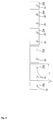
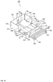
FIG. 1 is a perspective view depicting a battery module according to a first embodiment; -
FIG. 2 is a top view depicting the battery module; -
FIG. 3 is a lateral view depicting the battery module; -
FIG. 4 is a top view depicting a flexible flat cable; -
FIG. 5 is a top view depicting connecting members before the connecting members are integrated by a film made of an insulating resin; -
FIG. 6 is a top view depicting the connecting members after the connecting members are integrated by a film made of an insulating resin; -
FIG. 7 is a top view depicting the connecting members connected with the flexible flat cable; -
FIG. 8 is a perspective view depicting the connecting members connected with the flexible flat cable; -
FIG. 9 is a partially enlarged view schematically depicting a folded portion of the flexible flat cable; -
FIG. 10 is a top view partially depicting a battery module according to a second embodiment; -
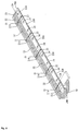
FIG. 11 is a top view depicting a first container member line; -
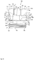
FIG. 12 is a top view depicting a left end container member; -
FIG. 13 is a perspective view depicting the end container member depicted inFIG. 12 ; -
FIG. 14 is a lateral view depicting the end container member depicted inFIG. 12 ; -
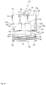
FIG. 15 is a top view depicting a right end container member;. -
FIG. 16 is a perspective view depicting the end container member depicted inFIG. 15 ; -
FIG. 17 is a top view depicting a first container member; -
FIG. 18 is a perspective view depicting the first container member depicted inFIG. 17 ; -
FIG. 19 is a lateral view depicting the first container member depicted inFIG. 17 ; -
FIG. 20 is a lateral view depicting the first container member line; and -
FIG. 21 is a top view explaining a process of connecting the flexible flat cable to the first container member line. -
- 10, 50: Battery module
- 11, 51: Electric cell
- 12, 52: Battery container
- 12A: Upper end surface (Outer wall surface)
- 13A, 53A: Electrode terminal (Positive electrode)
- 13B, 53B: Electrode terminal (Negative electrode)
- 15: Separator
- 16: Projection
- 20, 60: Bus bar
- 21A, 21B: Bus bar line
- 22A: Insulating resin portion
- 24, 64: Terminal insertion hole
- 30, 84: Voltage detecting line (Flexible flat cable)
- 31, 90: Mountain folded portion (Folded portion)
- 31 A, 90A: Folding line
- 32, 87: Connecting portion
- 33, 86: Insulating resin (of FFC)
- 34, 85: Conductor
- 70: Container member
- 75, 80: FFC container (Holder)
- 76, 81: FFC mounting portion
- 78, 83: FFC holder
- 91: Joint
- 92: Jointing projection
- 93: Jointing receiver
- A first embodiment according to the present invention will be described with reference to
FIGs. 1 to 9 . - A
battery module 10 according to this embodiment is usable as, for instance, a driving source for electric cars, hybrid cars or the like. As depicted inFIG. 1 , thebattery module 10 includes: a plurality ofelectric cells 11 juxtaposed transversely; a plurality of bus bars 20 (connecting members 20) connecting the plurality ofelectric cells 11 in series; and avoltage detecting line 30 measuring the voltage of eachelectric cell 11. In the following description, the "upper" direction and the "lower" direction will respectively be aligned with those depicted inFIG. 3 . - As depicted in
FIG. 1 , theelectric cell 11 includes: abattery container 12 made of a metal to internally contain a power generating element (not depicted); and bolt-shapedelectrode terminals symbol 13A while a negative electrode is represented by thesymbol 13B). Theelectrode terminals upper end surface 12A (terminal forming surface 12A) of thebattery container 12. Theelectric cells 11 are juxtaposed such that positive sides and negative sides ofelectric cells 11 adjacent to each other are opposite to each other. Accordingly, theelectrode terminals electrode terminals nuts 14 while interposed by the bus bars 20. - The plurality of
electric cells 11 is fixed by two holdingplates FIG. 2 . Aseparator 15 made of a resin is disposed between adjacent twoelectric cells FIG. 3 , theseparator 15 has aprojection 16 projecting upward from theterminal forming surface 12A of the battery container 12 (i.e., in a direction outward from anouter wall surface 12A of the battery container 12). Theprojection 16 is located at aclearance 23 provided between adjacent twobus bars - As depicted in
FIG. 2 , belt-shapedbus bar lines bus bars 20 are disposed on the plurality ofelectric cells 11 in a direction in which theelectric cells 11 are juxtaposed. Thebus bar lines electric cells 11 are juxtaposed. The belt-shapedvoltage detecting line 30, which extends in the direction in which theelectric cells 11 are juxtaposed, is disposed on each of thebus bar lines bus bar lines FIGs. 3 ,7 and8 ). - As depicted in
FIGs. 3 and6 , thebus bar lines resin portions 22A formed by heat laminating a film made of an insulating resin such as polypropylene (PP), polyvinyl chloride (PVC), polybutylene terephthalate (PBT) or polyethylene terephthalate (PET), and the insulatingresin portions 22A rim two longitudinal sides of thebus bar lines 21A and 21 B. In other words, thebus bar lines bus bars 20 with use of the insulatingresin portions 22A. - As depicted in
FIG. 2 , the plurality ofbus bars 20 in thebus bar lines hole bus bar 20A (detailed later) is set to be slightly greater than a width dimension of twoelectric cells separator 15 is interposed. - The bus bars 20 included in the
bus bar lines electrode terminals bus bar lines bus bar line 21A (i.e., the one located at the side closer to the reader inFIG. 2 ) has, at its both ends, single-hole bus bars 20B each provided with a singleterminal insertion hole 24. Between the two single-hole bus bars 20B and 20B located at the respective ends of thebus bar line 21 A, four two-hole bus bars 20A each provided with two terminal insertion holes 24 are disposed. Of the twobus bar lines bus bar line 21 B (i.e., the one located at the side away from the reader inFIG. 2 ) has five two-hole bus bars 20A. In this description, the "bus bar(s) 20" includes the two-hole bus bar(s) 20A and the single-hole bus bar(s) 20B. - As depicted in
FIG. 5 , the bus bars 20 each are substantially rectangular, and have the terminal insertion holes 24 and 24 through which theelectrode terminals - Shorter sides of the bus bars 20 are partially provided with insulating
resin portions 22B formed by heat laminating a film made of an insulating resin such as PP, PVC, PBT or PET. The shorter-side portions of the bus bars 20 at which the insulatingresin portions 22B are provided correspond to ends ofterminal connecting regions 25 for connection with theelectrode terminals resin portions 22B, the bus bars 20 are kept insulated from one another. Theclearance 23, which is provided between theterminal connecting regions 25 of the adjacent bus bars 20 and 20, serves as aprojection disposing clearance 23 at which theprojection 16 of theseparator 15 is disposed. - The bus bars 20 each connect (electrically) the
adjacent electrode terminals voltage detecting line 30 measuring the voltage of eachelectric cell 11. - In this embodiment, the
voltage detecting line 30 connected to the bus bars 20 is a flexible flat cable (FFC 30) formed by flatly encapsulating an outer circumference of aflat conductor 34 with an insulatingresin 33. - An example of
FFC 30 is a flexible flat cable formed by laminating a plurality of aligned copper foils (conductors 34) with a resin such as polyethylene terephthalate. Preferably, the thickness of theFFC 30 is 0.6 mm or more and 0.7 mm or less. - As depicted in
FIG. 1 , theFFC 30 is disposed on each of the twobus bar lines FFC 30 is bent to form a trapezoidal shape at the holdingplate 18 at the right end, and connected to abattery ECU 17 disposed on theelectric cells 11. Thebattery ECU 17, in which a micro computer, devices and the like are installed, has a known structure. Thebattery ECU 17 serves to detect the voltage, current, temperatures and the like of theelectric cells 11 and control the charging and discharging of eachelectric cell 11. - The
FFC 30 has mountain folded portions 31 (folded portions 31) respectively at the portions to be disposed between the adjacent bus bars 20 and 20. The mountain foldedportions 31 are formed by folding theFFC 30 atfolding lines 31A extending in a direction substantially perpendicular to the longitudinal direction of the FFC 30 (direction crossing the longitudinal direction of the FFC 30). Projecting dimensions Z of the mountain foldedportions 31 are preferably 10 mm or less (see,FIG. 9 ). - The
FFC 30 has connectingportions 32 at which theFFC 30 is connected to the bus bars 20. The connectingportions 32 connecting theFFC 30 with the bus bars 20 are formed by: peeling the insulatingresin 33 of theFFC 30 by laser or the like to expose theconductors 34; and connecting the exposedconductors 34 with the bus bars 20 by a variety of welding methods (such as resistance welding, ultrasonic welding or soldering). Of the above welding methods, the resistance welding is preferably usable at low cost. - In the next description, a method of attaching the bus bars 20 and the
voltage detecting line 30 will be described. - The insulating
resin 33 of theFFC 30 is peeled by laser (not depicted) to expose theconductors 34 respectively corresponding to the bus bars 20. Then, the predetermined portions of theFFC 30 are bent at the foldedlines 31A substantially perpendicular to the longitudinal direction of theFFC 30 to form the mountain foldedportions 31, and the end of theFFC 30 to be connected to theECU 17 is bent to form a trapezoidal shape (see,FIG. 4 ). - At the same time as the processing of the
FFC 30, or before or after the processing of theFFC 30, thebus bar lines hole bus bars 20A are prepared. These prepared bus bars 20 are subjected to plating as needed. - Subsequently, five two-
hole bus bars 20A are aligned with predetermined intervals interposed between each other such that the terminal insertion holes 24 are aligned in a line. On the other hand, the two single-hole bus bars 20B and the four two-hole bus bars 20A, which are to be located between the two single hole bus bars 20B, are aligned with predetermined intervals interposed between each other such that the terminal insertion holes 24 are aligned in a line (see,FIG. 5 ). - Then, portions of the short sides of the bus bars 20 (the ends of the terminal connecting regions 25) are sandwiched between films made of an insulating resin, and subjected to heat laminating. Thereafter, the longitudinal sides of the bus bars 20 are sandwiched between films made of an insulating resin, and subjected to heat laminating. By performing the heat laminating on the films made of an insulating resin, the two longitudinal sides of the bus bars 20 and the portions of the short sides thereof are provided with the insulating
resin portions FIG. 6 ). The insulatingresin portions 22A provided to the longitudinal sides of the bus bars 20 are continuously formed so as to connect the adjacent bus bars with each other, and thus the plurality of bus bars 20 is integrated by the insulatingresins 22A. At the time of the heat laminating, adhesive may be used as needed. - By mounting the
FFC 30 onto thebus bar lines conductor 34 of theFFC 30 with the bus bars 20 by welding, thebus bar lines FFC 30 are obtained (see,FIGs. 7 and8 ). - Then, ten
electric cells 11 are transversely juxtaposed such that theelectrode terminals electric cells bus bar lines FFC 30, which are prepared in the above-described process, are subsequently mounted onto anupper surface 12A (theterminal forming surface 12A) of theelectric cells 11. - Thereafter, as depicted in
FIG. 1 , theelectrode terminals electric cells 11 are all inserted into all of the terminal insertion holes 24 of the bus bars 20. Further, as depicted inFIG. 1 , theelectrode terminals electrode terminals battery module 10 mounted with the bus bars 20 and thevoltage detecting line 30 is completed. - According to this embodiment, the following advantageous effects are obtained.
- The
battery module 10 according to this embodiment includes theFFC 30 as the component for jointing together the plurality ofbus bars 20 electrically connecting theelectrode terminals FFC 30 to be disposed between the adjacent bus bars 20 and 20 are provided with the foldedportions 31 formed by folding theFFC 30 at the folding lines extending in the direction crossing the longitudinal direction of theFFC 30. Thus, according to this embodiment, even when pitches between theadjacent electrode terminals electric cells 11 of thebattery module 10 are not constant, or even when the pitches between theelectrode terminals electric cells 11 of thebattery module 10 in the direction in which theelectric cells 11 are juxtaposed, such non-constancy of the pitches between theelectrode terminals portions 31 provided to theFFC 30. Resultantly, in thebattery module 10 according to this embodiment, non-constancy of the pitches between theadjacent electrode terminals - Further, according to this embodiment, since the
FFC 30 is a voltage detecting line measuring the voltage of theelectric cells 11, theFFC 30 not only connects the bus bars 20 but also serves as the voltage detecting line detecting the voltage of theelectric cells 11. Therefore, no other voltage detecting line than theFFC 30 is required to be separately connected to thebattery module 10, and thus the number of components is reducible. - In addition, according to this embodiment, the flat-shaped
FFC 30 is used as thevoltage detecting line 30, and theconductors 34 of theFFC 30 are directly connected to the bus bars 20. Therefore, the connection structure of thevoltage detecting line 30 saves space in the upper and lower direction of the electric cells 11 (the thickness direction of theterminal forming surface 12A) (see,FIG. 3 ), and the connection structure of the voltage detecting line is downsized in thebattery module 10. Further, with the above structure, theFFC 30 is connectable to the bus bars 20 by a low-cost method such as resistance welding or ultrasonic welding, which also contributes to a cost reduction. - According to this embodiment, the plurality of bus bars 20 is integrated together by the insulating
resin portions 22A formed by heat laminating the insulating resin films. Thus, this structure prevents detachment of the bus bars 20 and thevoltage detecting line 30 due to the stress applied onto the connectingportions 32 between the bus bars 20 and thevoltage detecting line 30. - Further, according to this embodiment, the
electric cells 11 have the metal-madebattery containers 12, and the resin-madeseparators 15 having theprojections 16 projecting outward from theupper surface 12A of thebattery containers 12 are disposed between the adjacentelectric cells separators 15. As the consequence, the number of components is reducible also in thebattery module 10 including theelectric cells 11 provided with the metal-madebattery containers 12. - A second embodiment according to the present invention will be described with reference to
FIGs. 10 to 21 . - A
battery module 50 according to this embodiment is usable as, for instance, a driving source for electric cars, hybrid cars or the like. As depicted inFIG. 10 , thebattery module 50 includes: a plurality ofelectric cells 51 juxtaposed transversely; a plurality of bus bars 60 (connecting members 60) connecting the plurality ofelectric cells 51 in series; and a plurality ofcontainer members 70 containing and holding anFFC 84 used as a voltage detecting line for measuring the voltage of eachelectric cell 51. In the following description, the "upper direction" and the "lower direction" will respectively be aligned with those depicted inFIGs. 14 and19 . - As depicted in
FIG. 10 , thebattery cell 51 includes: a battery container 52 made of a resin to internally contain a power generating element (not depicted); and bolt-shapedelectrode terminals symbol 53A while a negative electrode is represented by thesymbol 53B). Theelectrode terminals upper end surface 52A (terminal forming surface 52A) of the battery container 52. Thebattery cells 51 are juxtaposed such that positive sides and negative sides ofadjacent battery cells 51 are opposite to each other. Accordingly, theelectrode terminals electrode terminals nuts 54 while interposed by the bus bars 60 contained in thecontainer members 70. Although not depicted in detail, the plurality ofelectric cells 51 is fixed by two holding plates as in the first embodiment. - As depicted in
FIG. 10 , the plurality ofcontainer members 70 is juxtaposed on anelectric cell line 50A formed by the plurality ofelectric cells 51, in a direction in which theelectric cells 51 are juxtaposed. With this arrangement,container member lines container member lines electric cells 51 are juxtaposed, each contain the bus bars 60 and hold a belt-shapedvoltage detecting line 84 disposed in the direction in which theelectric cells 51 are juxtaposed (see,FIGs. 10 and11 ). In this description, thecontainer member line 71A (i.e., the one located at the side closer to the reader inFIG. 10 ) will be referred to as a firstcontainer member line 71A, and thecontainer member line 71 B (i.e., the one located at the side away from the reader inFIG. 10 ) will be referred to as a secondcontainer member line 71 B. - As depicted in
FIG. 11 , the firstcontainer member line 71A is formed by eleven (plural)container members 70. The elevencontainer members 70 in the firstcontainer member line 71A are integrally jointed together by jointingjoints 91 and attaching theFFC 84 to the container members 70 (seeFig. 20 ). TheFFC 84 is connected to a battery ECU (not depicted) like theFFC 30 in the first embodiment. - Although not depicted in detail, the second
container member line 71 B is formed by twelve (plural)container members 70. The twelvecontainer members 70 in the secondcontainer member line 71 B are integrally jointed together by the jointing thejoints 91 and theFFC 84. - Of the eleven
container members 70 in the firstcontainer member line 71A,end container members 70B respectively located at right and left ends depicted inFIG. 11 are to be approximately 1.5 times as great ascontainer members 70A located at positions other than the ends (hereinafter referred to as "first container members 70A"). The twelve container members in the secondcontainer member line 71 B each have the same size and shape as thefirst container members 70A, and these twelve container members are also referred to as "first container members 70A." In this embodiment, the "container members 70" will be used when thefirst container members 70A and theend container members 70B need not to be distinguished. - The two
end container members 70B, which are made of a synthetic resin, are mounted to bridge adjacent threeelectric cells 51. As depicted inFIG. 11 , eachend container member 70B includes: twobus bar containers bus bars FFC container 75 containing theFFC 84 measuring the voltage of theelectric cells 51. - Each
end container member 70B is formed by integrally molding a synthetic resin. The longitudinal dimension of eachend container member 70B is slightly smaller than the width dimension of the threeelectric cells 51. With this arrangement, when theend container member 70B is mounted on theelectric cell line 50A, a small clearance is made between theend container member 70B and thefirst container member 70A adjacent thereto (see,FIG. 10 ). - In the first
container member line 71A, the twoend container members 70B are symmetrical to each other, as depicted inFIG. 11 . Specifically, each of theend container members bus bar container 72 containing a single-hole bus bar 60B provided with a single terminal insertion hole 64 (detailed later) at its side closer to an end of theelectric cell line 50A. On the other hand, each of theend container members bus bar container 74 containing a two-hole bus bar 60A provided with two terminal insertion holes 64 (detailed later) at its side closer to the center of theelectric cell line 50A. - In this description, when the two
end container members 70B are distinguished from each other, theend container member 70B located closer to the left end inFIG. 11 will be referred to as a "leftend container member 701", while theend container member 70B located closer to the right end inFIG. 11 will be referred to as a "rightend container member 702". The "end container member(s) 70B" will collectively refer to the leftend container member 701 and the rightend container member 702. Arrangements common in the twoend container members - Description will be made with respect to the two types of the
bus bars end container members 70B. - The single-hole bus bars 60B and the two-
hole bus bars 60A each have substantially a T shape (see,FIGs. 11 and21 ). The bus bars 60 are made of a metal such as copper, copper alloy or stainless steel (SUS). Widely-shaped portions of the bus bars 60 serve asregions 65 at which the terminal insertion holes 64 are provided, i.e.,terminal connecting regions 65 to be electrically connected to theelectrode terminals electric cells 51. On the other hand,regions 66 formed to be narrower than theterminal connecting regions 65 serve as detecting-line connecting regions 66 to be connected to theFFC 84. Of the corners of theterminal connecting region 65 of eachbus bar 60, two corners disposed along container walls of thebus bar containers FIG. 11 (hereinafter referred to asrear walls - The first
bus bar container 72 containing the single-hole bus bar 60B is mounted onto theelectric cell 51 disposed at the end. On the other hand, the secondbus bar container 74 containing the two-hole bus bar 60A is mounted to bridge twoelectric cells 51. As is clear from the comparison ofFIG. 12 withFIG. 15 , positioning of the firstbus bar container 72 and the secondbus bar container 74 in the leftend container member 701 and that in the rightend container member 702 are opposite to each other. - As depicted in
FIG. 11 , the firstbus bar container 72 is configured to contain theterminal connecting region 65 of the single-hole bus bar 60B provided with the singleterminal insertion hole 64. The firstbus bar container 72 hascontainer walls terminal forming surface 52A of theelectric cells 51, and thecontainer walls terminal connecting region 65 of the single-hole bus bar 60B (see,FIGs. 12 ,13 ,15 and16 ). Thecontainer wall 72B of the firstbus bar container 72, which is a container wall located closer to the FFC container 75 (i.e., a container wall located closer to the reader inFIGs. 12 and15 , and hereinafter referred to asfront wall 72B), is partially open. - A bottom wall of the first bus bar container 72 (i.e., a wall at which the first bus bar container is mounted on the
terminal forming surface 52A of the electric cells 51) is substantially rectangularly cut off except for mountingportions 73A. The mountingportions 73A are formed to follow the laterally-providedcontainer walls lateral walls terminal connecting region 65 of the single-hole bus bar 60B. - The
lateral walls bus bar container 72 are respectively provided withslits 73B extending upward from the lower ends of thelateral walls lateral walls slits 73B are positioned at an end closer to an opening 72C and at a position adjacent to the mountingportion 73A. Between the twoslits claw 73C mounted on an upper surface of the single-hole bus bar 60B and to lock the single-hole bus bar 60B is provided (see,FIGs. 13 and14 ). - As depicted in
FIGs. 12 and15 , an escape space S allowing the lockingclaw 73C provided to thelateral wall 72E to escape is secured between thelateral wall 72E (i.e., the wall closer to the secondbus bar container 74, of the twolateral walls lateral wall 74E (detailed later) of the secondbus bar container 74. - The second
bus bar container 74 is configured to contain theterminal connecting region 65 of the two-hole bus bar 60A provided with the two terminal insertion holes 64. The secondbus bar container 74 hascontainer walls terminal forming surface 52A of theelectric cells 51, and thecontainer walls terminal connecting region 65 of the two-hole bus bar60A (see,FIGs. 12 ,13 ,15 and16 ). Thecontainer wall 74B of the secondbus bar container 74, which is a container wall located closer to the FFC container 75 (i.e., acontainer wall 74B located closer to the reader inFIGs. 12 and15 , and hereinafter referred to asfront wall 74B), is partially open, and separated into two portions. Of the twofront walls bus bar container 74, thefront wall 74B closer to the firstbus bar container 72 is continuously integrated with thefront wall 72B of the first bus bar container 72 (hereinafter referred to as integrated wall 741). As depicted inFIGs. 13 and16 , substantially a central portion of theintegrated wall 741 is provided with afirst locking hole 741A locking athird locking projection 78E (detailed later) of anFFC holder 78. - A bottom wall of the second bus bar container 74 (i.e., a wall at which the second
bus bar container 74 is mounted on theterminal forming surface 52A of the electric cells 51) is cut off except forend mounting portions 74F and acenter mounting portion 74G. Theend mounting portions 74F are formed to follow the laterally-providedcontainer walls lateral walls terminal connecting region 65 of the two-hole bus bar 60A, while thecenter mounting portion 74G is configured to be mounted with a substantially central portion of theterminal connecting region 65 of the two-hole bus bar 60A. Of thelateral walls bus bar container 74, the lateral wall closer to the firstbus bar container 72 will be referred to as thelateral wall 74E. - A substantially central portion of the
rear wall 74A of the secondbus bar container 74 is provided with twoslits rear wall 74A. Between the twoslits claw 74J mounted on an upper surface of the two-hole bus bar 60A to lock the two-hole bus bar 60A is provided. In the secondbus bar container 74, the lockingclaw 74J is positioned at a position corresponding to thecenter mounting portion 74G. - The
rear wall 74A of the secondbus bar container 74 is continuously integrated with therear wall 72A of the firstbus bar container 72. In the secondbus bar container 74, therear wall 74A is differently structured, depending on whether therear wall 74A is for theleft container member 701 or for theright container member 702. - As depicted in
FIGs. 12 and13 , in the leftend container member 701, therear wall 74A of the secondbus bar container 74 is provided with afirst jointing projection 92A projecting outward from an outer wall surface of therear wall 74A of the secondbus bar container 74 and inserted into athird jointing receiver 93C (described later) provided to thefirst container member 70A adjacent thereto. - On the other hand, as depicted in
FIG. 16 , in the rightend container member 702, therear wall 74A of the secondbus bar container 74 is partially rectangularly cut off to provide afirst jointing receiver 93A. Thefirst jointing receiver 93A is configured to receive a third joiningprojection 92C (described later) provided to thefirst container member 70A adjacent thereto. - In the next description, the
FFC container 75 of theend container member 70B will be described. The FFC container 75 (an example of the "holder" according to the present invention) includes: a substantially rectangularFFC mounting portion 76 onto which the detecting-line connecting region 66 of eachbus bar 60 and theFFC 84 are mounted; a substantiallyrectangular FFC holder 78 disposed to cover theFFC 84 mounted on theFFC mounting portion 76 and holding theFFC 84 by sandwiching theFFC 84 with theFFC mounting portion 76; and ahinge 77 jointing theFFC mounting portion 76 and theFFC holder 78 together. TheFFC mounting portion 76 and theFFC holder 78 are formed substantially in parallel to each other. - The
FFC mounting portion 76 is provided with: a first cut-offportion 76A continued from the cut-off portion of the bottom wall of the firstbus bar container 72 and being cut off to define a T-shape as a whole; and a second cut-offportion 76B being cut off in a T-shape and provided at a substantially central portion of a region along the secondbus bar container 74. - An edge of the
FFC mounting portion 76 which is along the first cut-offportion 76A is provided with a first locking projection 76C locking the detecting-line connecting region 66 of the single-hole bus bar 60B. On the other hand, an edge of theFFC mounting portion 76 which is along the second cut-offportion 76B is provided with asecond locking projection 76D locking the detecting-line connecting region 66 of the two-hole bus bar 60A. Further, theFFC mounting portion 76 is provided with two types of busbar mounting portions hole bus bar 60A and the single-hole bus bar 60B. In theFFC mounting portion 76, the busbar mounting portion 76E to be fittably engaged with the single-hole bus bar 60B will be referred to as the first busbar mounting portion 76E, while the busbar mounting portion 76F to be fittably engaged with the two-hole bus bar 60A will be referred to as the second busbar mounting portion 76F. - Each longitudinal end of the
FFC mounting portion 76 is provided with twoFFC fixing projections 76G projecting from theFFC mounting portion 76 and fixing theFFC 84. In theFFC mounting portion 76, fourFFC fixing projections 76G are provided in total. - In the next description, a difference between the structure of the end portion of the
FFC mounting portion 76 in the leftend container member 701 and that in the rightend container member 702 will be described. - As depicted in
FIGs. 12 and13 , in the leftend container member 701, an end of the FFC mounting portion 76 (right end in the depiction) is provided with threesecond jointing projections 92B projecting from the end of theFFC mounting portion 76 to extend outward. The threesecond jointing projections 92B are configured to be inserted intofourth jointing receivers 93D (described later) provided to anFFC mounting portion 81 of thefirst container member 70A adjacent thereto. - As depicted in
FIGs. 15 and16 , in the rightend container member 702, an end of the FFC mounting portion 76 (left end in the depiction) is provided with threesecond jointing receivers 93B recessed from the end of theFFC mounting portion 76. The threesecond jointing receivers 93B are configured to receivefourth jointing projections 92D (described later) provided to theFFC mounting portion 81 of thefirst container member 70A adjacent thereto. - A surface of the
FFC holder 78 to be in contact with the FFC 84 (i.e., the upper surface inFIGs. 13 and16 ) is provided with fourFFC fixing holes 78A at its corners and also with a plurality ofribs 78B extending in the longitudinal direction of theFFC holder 78. The fourFFC fixing holes 78A are configured to be fittably engaged respectively with the fourFFC fixing projections 76G provided to theFFC mounting portion 76. Theribs 78B serve to hold theFFC 84. An edge of theFFC holder 78 closer to thehinge 77 is provided with a first escape recess 78C and asecond escape recess 78D respectively allowing the first locking projection 76C and thesecond locking projection 76D provided to theFFC mounting portion 76 to escape when theFFC holder 78 is superposed onto theFFC mounting portion 76. - An edge of the
FFC holder 78 opposite to the hinge 77 (i.e., the edge located closer to the reader inFIGs. 12 and15 ) is provided with thethird locking projection 78E to be locked to thefirst locking hole 741 A provided to theintegrated wall 741 when theFFC holder 78 is superposed onto theFFC mounting portion 76. - In the next description, the
first container member 70A will be described. Thefirst container member 70A, which is made of a synthetic resin, is mounted to bridge twoelectric cells 51 adjacent to each other. As depicted inFIG. 11 , thefirst container member 70A includes: abus bar container 79; and anFFC container 80 containing theFFC 84 for measuring the voltage of theelectric cells 51. Thebus bar container 79 and theFFC container 80 are formed by integrally molding a synthetic resin. - The longitudinal dimension of the
first container member 70A is slightly smaller than the width dimension of the twoelectric cells 51. With this arrangement, a slight clearance is secured between thefirst container members 70A adjacent to each other. - As depicted in
FIG. 11 , thefirst container member 70A contains the two-hole bus bar 60A provided with the two terminal insertion holes 64. The two-hole bus bar 60A to be contained in thefirst container member 70A is structured similarly to the two-hole bus bar 60A to be contained in theend container member 70B, and thus a detailed description thereof is omitted. - As depicted in
FIG. 10 , thebus bar container 79 of thefirst container member 70A is disposed to bridge twoelectric cells 51. Thebus bar container 79 hascontainer walls terminal forming surface 52A of theelectric cells 51, and thecontainer walls terminal connecting region 65 of the two-hole bus bar 60A (see,FIGs. 11 and17 ). Thecontainer wall 79B of thebus bar container 79, which is a container wall located closer to the FFC container 80 (i.e., a container wall located closer to the reader inFIG. 17 , and hereinafter referred to asfront wall 79B), is partially open. - A bottom wall of the
bus bar container 79 of thefirst container member 70A (i.e., a wall at which thebus bar container 79 is mounted on theterminal forming surface 52A of the electric cells 51) is cut off except forend mounting portions 79F and acenter mounting portion 79G. Theend mounting portions 79F are formed to follow the laterally-providedcontainer walls lateral walls terminal connecting region 65 of the two-hole bus bar 60A, while thecenter mounting portion 79G is mounted with a substantially central portion of theterminal connecting region 65 of the two-hole bus bar 60A. - As depicted in
FIG. 16 , a substantially central portion of therear wall 79A of thebus bar container 79 of thefirst container member 70A is provided with twoslits rear wall 79A. Between the twoslits claw 79J mounted on an upper surface of the two-hole bus bar 60A and locking the two-hole bus bar 60A is provided. In thebus bar container 79, the lockingclaw 79J is positioned at a position corresponding to thecenter mounting portion 79G. - As depicted in
FIG. 18 , the twofront walls bus bar container 79 of thefirst container member 70A are provided respectively with second locking holes 791 and 791 lockingfifth locking projections 83E (detailed later) of anFFC holder 83. - As depicted in
FIGs. 17 and18 , an outer wall surface of therear wall 79A of thebus bar container 79 of thefirst container member 70A is provided with thethird jointing projection 92C projecting outward from the depicted right end of therear wall 79A and to be inserted into ajointing receiver 93 of thecontainer member 70 adjacent thereto (specifically, thethird jointing receiver 93C of thefirst container member 70A or thefirst jointing receiver 93A of the right end container member 702). - In addition, the
rear wall 79A of thebus bar container 79 of thefirst container member 70A is partially rectangularly cut off from the depicted left end to provide athird jointing receiver 93C. Thethird jointing receiver 93C is configured to receive a jointing projection 92 of thecontainer member 70 adjacent thereto (specifically, thethird jointing projection 92C of thefirst container member 70A or thefirst jointing projection 92A of the left end container member 701). - The
FFC container 80 of thefirst container member 70A (an example of the "holder" according to the present invention) includes: an substantially rectangularFFC mounting portion 81 mounted with the detecting-line connecting region 66 of the two-hole bus bar 60A and theFFC 84; the substantiallyrectangular FFC holder 83 disposed to cover theFFC 84 mounted on theFFC mounting portion 81 and holding theFFC 84 by sandwiching theFFC 84 with theFFC mounting portion 81; and ahinge 82 jointing theFFC mounting portion 81 and theFFC holder 83 together. TheFFC mounting portion 81 and theFFC holder 83 are formed substantially in parallel to each other. - The
FFC mounting portion 81 of thefirst container member 70A is provided with a third cut-offportion 81 A formed by cutting off a substantially central portion of a region along thebus bar container 79 in a T-shape. - An edge of the
FFC mounting portion 81 of thefirst container member 70A which is along the third cut-offportion 81A is provided with afourth locking projection 81 C locking the detecting-line connecting region 66 of the two-hole bus bar 60A. Further, theFFC mounting portion 81 is provided with a third busbar mounting portion 81 E recessed from the other portions to be fittably engaged with the two-hole bus bar 60A. - Similarly to the
end container member 70B, each longitudinal end of theFFC mounting portion 81 of thefirst container member 70A is also provided with twoFFC fixing projections 81 F projecting from theFFC mounting portion 81 and fixing theFFC 84. In theFFC mounting portion 81, fourFFC fixing projections 81 F are provided in total. - As depicted in
FIGs. 17 and18 , in theFFC mounting portion 81 of thefirst container member 70A, an end of the FFC mounting portion 81 (right end in the depiction) is provided with threefourth jointing projections 92D projecting from the end of theFFC mounting portion 81 to extend outward. The threefourth jointing projections 92D are configured to be inserted into thejointing receivers 93 provided to thecontainer member 70 adjacent thereto (specifically, thefourth jointing receivers 93D of thefirst container member 70A or thesecond jointing receivers 93B of the right end container member 702). - As depicted in
FIGs. 17 and18 , in theFFC mounting portion 81 of thefirst container member 70A, an end of the FFC mounting portion 81 (left end in the depiction) is provided with threefourth jointing receivers 93D recessed from the end of theFFC mounting portion 81. The threefourth jointing receivers 93D receive the jointing projections 92 provided to thecontainer member 70 adjacent thereto (specifically, thefourth jointing projections 92D of thefirst container member 70A or thesecond jointing projections 92B of the left end container member 701). - A surface of the
FFC holder 83 of thefirst container member 70A to be in contact with the FFC 84 (i.e., the upper surface inFIG. 18 ) is provided with fourFFC fixing holes 83A at its corners and also with a plurality ofribs 83B extending in the longitudinal direction of theFFC holder 83. The fourFFC fixing holes 83A are configured to be fittably engaged respectively with the fourFFC fixing projections 81 F provided to theFFC mounting portion 81. Theribs 83B serve to hold theFFC 84. TheFFC holder 83 is also provided with anescape recess 83C allowing athird locking projection 81 C provided to theFFC mounting portion 81 to escape when theFFC holder 83 is superposed onto theFFC mounting portion 81. - An edge of the
FFC holder 83 opposite to the hinge 82 (i.e., the edge located closer to the reader inFIGs. 17 and18 ) is provided with twofifth locking projection 83E to be locked to thesecond locking hole integrated wall 741 when theFFC holder 83 is superposed onto theFFC mounting portion 81. - As depicted in
FIG. 10 , theFFC 84 to be contained in theFFC holder 75 of theend container member 70B and theFFC container 80 of thefirst container member 70A extend in the direction in which theelectric cells 51 are juxtaposed (in the right and left direction inFIG. 10 ). Also as depicted inFIG. 10 , theFFC 84 is disposed on each of the firstcontainer member line 71 A and the secondcontainer member line 71 B. - An example of the
FFC 84 is a conductor line laminated with an insulating resin 86 such as polyethylene terephthalate, in which a plurality ofcopper conductors 85 is juxtaposed such that theconductors 85 are insulated from one another. As depicted inFIGs. 11 and21 , a longitudinal edge of theFFC 84 is provided with a plurality of attachingholes 89 to be engaged with theFFC fixing projections FFC mounting portions - Similarly to the
FFC 30 according to the first embodiment, theFFC 84 has mountain folded portions 90 (folded portions 90) respectively at the portions to be disposed between the bus bars 60 and 60 adjacent to each other (in this embodiment, in the vicinity of decoupling portions 88). Except for the foldedportions 90, theFFC 84 is held by theFFC containers - The
FFC 84 has connecting portions 86 at which theFFC 84 is connected to the bus bars 60. In this embodiment, the seven (plural)conductors 85 included in theFFC 84 are connected to the bus bars 60 such that each adjacent pair ofconductors 85 is connected to eachbus bar 60. The connecting portions 86 at which theFFC 84 is connected to the bus bars 60 are formed by a method such as the one exemplified in the first embodiment. While two circuits are formed when the adjacent pair ofconductors 85 is connected to thebus bar 60, one of the two circuits is decoupled from the other one of the two circuits by thedecoupling portion 88. - The
FFC 84 used in this embodiment is configured to be provided with up to seven connecting portions 86 for connection to the bus bars 60. Accordingly, when the number of the bus bars 60 connected with theFFC 84 is eight or more, two or more FFCs 84 are used for connecting the bus bars 60 with theFFCs 84. In this embodiment, as depicted inFIG. 21 , since the total number of the bus bars 60 to be contained in the firstcontainer member line 71 A is thirteen, the FFC 84 (84A) is connected to the eighth to thirteenth bus bars 60 counted from the left inFIG. 21 (i.e., thethirteenth bus bar 60 is the one located at the right end) and fixed to theFFC mounting portions FIG. 11 , theFFC 84B longer than theFFC 84A is connected to the first to seventh bus bars 60 counted from the left inFIG. 11 and disposed to be superposed onto the previously-mountedFFC 84A. - The mounting process of the
FFC 84 to the secondcontainer member line 71 B is not depicted in detail, but is similar to the mounting process of theFFC 84 to the first container member line 71 A. Since the total number of the bus bars 60 to be contained in the secondcontainer member line 71 B is twelve, twoFFCs 84 having different lengths are used for connecting the bus bars 60 with theFFCs 84. - In the next description, a method of assembling the
battery module 50 according to this embodiment will be briefly described. In this embodiment, an arrangement in which twenty fourelectric cells 51 are linearly connected in series will be exemplarily described. - The twenty four
electric cells 51 are juxtaposed with theirterminal forming surfaces 52A oriented upward, and theelectric cell line 50A is obtained. Then, one leftend container member 701, one rightend container member 702 and twenty onefirst container members 70A are prepared. - The FFCs 84 to be mounted on the first
container member line 71A and the secondcontainer member line 71 B are also prepared. Specifically, the insulating resin 86 of theFFCs 84 is peeled with laser (not depicted) to expose twoconductors 85 adjacent to each other corresponding to eachbus bar 60, and one of the exposedconductors 85 is provided with the decoupling portion 88 (see,FIG. 11 ). Thedecoupling portion 88 is formed by punching a part of the targetedconductor 85 with a punch or the like. Then, the predetermined portions of theFFCs 84 are bent atfolding lines 90A extending in a direction substantially perpendicular to the longitudinal direction of theFFCs 84, to form the mountain folded portions 90 (folded portions 90). - Each of the
end container members 70B contains one single-hole bus bar 60B and one two-hole bus bar 60A, and each of thefirst container members 70A contains the two-hole bus bar 60A. - The accommodating operations are conducted by disposing the detecting-
line connecting regions 66 of the single-hole bus bars 60B onto the first busbar mounting portions 76E, and disposing theterminal connecting regions 65 of the single-hole bus bars 60B onto the firstbus bar container 72. By disposing the detecting-line connecting regions 66 of the single-hole bus bars 60B onto the first busbar mounting portions 76E, the single-hole bus bars 60B are locked by the first locking projections 76C. When theterminal connecting region 65 of the single-hole bus bar 60B is inserted into the firstbus bar container 72, the ends of the single-hole bus bar 60B abut on the two lockingclaws claws hole bus bar 60B are mounted on the mountingportions 73A provided to thelateral walls bus bar container 72, the two lockingclaws terminal connecting region 65 of the single-hole bus bar 60B is locked while contained in the firstbus bar container 72. - Similarly to the single-hole bus bars 60B, the accommodating operations are conducted with respect to the two-hole bus bars 60A. In the
end container member 70B, the detecting-line connecting region 66 of the two-hole bus bar 60A is locked by thesecond locking projection 76D, and theterminal connecting region 65 of the two-hole bus bar 60A is locked by the lockingclaw 74J of the secondbus bar container 74. In thefirst container member 70A, the detecting-line connecting region 66 of the two-hole bus bar 60A is locked by thefourth locking projection 81 C, and theterminal connecting region 65 of the two-hole bus bar 60A is locked by the lockingclaw 79J of thebus bar container 79. - Subsequently, the first
container member line 71A and the secondcontainer member line 71 B are prepared. - The left
end container member 701, the ninefirst container members 70A and the rightend container member 702 are sequentially jointed together such that their terminal insertion holes 64 are aligned in one line. Thefirst jointing projection 92A and thesecond jointing projections 92B of the leftend container member 701 are respectively inserted into thethird jointing receiver 93C and thefourth jointing receivers 93D of thefirst container member 70A, and the leftend container member 701 is thereby connected with thefirst container member 70A. Thethird jointing projection 92C and thefourth jointing projections 92D of thefirst container member 70A connected to the leftend container member 701 are respectively inserted into thethird jointing receiver 93C and the fourth joiningreceivers 93D of anotherfirst container member 70A, and the twofirst container members 70A are thereby jointed together. By repeating the similar jointing operations, the leftend container member 701 is connected with the ninefirst container members 70A. When thethird jointing projection 92C and thefourth jointing projections 92D of thefirst container member 70A disposed at the right end are respectively inserted into thefirst jointing receiver 93A and thesecond jointing receivers 93B of the rightend container member 702, the jointing operations are completed, and theFFC mounting portions container members - When the
FFCs 84 are fixed to theFFC mounting portions FFC fixing projections FFC mounting portions holes 89 of theFFC 84, the foldedportions 90 of theFFC 84 are positioned between thecontainer members 70A. At this time, first of all, theshorter FFC 84A is fixed to theFFC mounting portions bus bar 60 is connected with theFFC 84. In connecting eachbus bar 60 with theFFC 84, the adjacent two exposedconductors 85 are connected to the correspondingbus bar 60 by welding. In this manner, the firstcontainer member line 71A with theFFC 84A connected is obtained as depicted inFIG. 21 . Subsequently, the adjacent twoconductors 85 of thelonger FFC 84B are welded to the correspondingbus bar 60, and theFFC 84B is connected to thebus bar 60. In this manner, the firstcontainer member line 71 A depicted inFIGs. 11 and20 is obtained. - Then, the
third locking projection 78E of theFFC holder 78 and thefifth locking projections FFC holder 83 are respectively locked by thefirst locking hole 741 A of theintegrated wall 741 of the secondbus bar container 74 and the second locking holes 791 and 791 of thebus bar container 79. TheFFC fixing holes FFC holders FFC fixing projections FFC mounting portions FFCs 84 are held, and then the firstcontainer member line 71A is obtain ed. - Likewise, by jointing the twelve
first container members 70A together such that their terminal insertion holes 64 are aligned in one line, theFFC mounting portions 81 of the twelvecontainer members 70A are linearly arranged. By inserting the FFCfi xing projections 81 F of the linearly-arrangedFFC mounting portions 81 into the attachingholes 89 of theFFCs 84, theFFCs 84 are fixed to theFFC mounting portions 81, and eachbus bar 60 is connected with theFFCs 84 by the method similar to the one described above. Subsequently, thefifth locking projections FFC holder 83 are respectively locked by the second locking holes 791 and 791 of thebus bar container 79, and theFFC fixing holes 83A of theFFC holder 83 are also engaged with theFFC fixing projections 81 F of theFFC mounting portions 81. With these operations, theFFCs 84 are held, and the secondcontainer member line 71 B is obtained. - The first
container member line 71A and the secondcontainer member line 71 B, which are respectively prepared in the above-described processes, are respec tively mounted on the predetermined positions of theterminal forming surface 52A of theelectric cell line 50A. By inserting theelectrode terminals electric cells 51 into the terminal insertion holes 64 of the bus bars 60 contained in thecontainer members electrode terminals electrode terminals battery module 50 according to this embodiment is obtained. - According to this embodiment, the following advantageous effects are obtained.
- Like the battery module according to the first embodiment, the
battery module 50 according to this embodiment includes theFFC 84 as the component for jointing togeth er the plurality ofbus bars 60 electrically connecting theelectrode terminals FFC 84 to be disposed between the adjacent bus bars 60 and 60 are provided with the foldedportions 90 formed by folding theFFC 84 at the folding lines extending in the direction crossing the longitudinal direction of theFFC 84. Thus, according to this embodiment as well, even when pitches between theadjacent electrode terminals electric cells 51 of thebattery module 50 are not constant, or even when the pitches between theelectrode terminals electric cells 51 of thebattery module 50 in the direction in which theelectric cells 51 are juxtaposed, such non-constancy of the pitches between theelectrode terminals portions 90 provided to theFFC 84. Resultantly, also in thebattery module 50 according to this embodiment, non-constancy of the pitches between theadjacent electrode terminals - Further, like the first embodiment, according to this embodiment as well, the
FFC 84 serves as the voltage detecting line. Thus, theFFC 84 not only connects the bus bars 60 but also serves as the voltage detecting line detecting the voltage of theelectric cells 51. As a consequence, according to this embodiment, no other voltage detecting line than theFFC 84 is required to be separately connected to thebattery module 50, and thus the number of components is reducible. - In addition, according to this embodiment, the flat-shaped
FFC 84 is used as the voltage detecting line, and theconductors 85 of theFFC 84 are directly connected to the bus bars 60. Therefore, the connection structure of thevoltage detecting line 84 saves space in the upper and lower direction of the electric cells 51 (the thickness direction of theterminal forming surface 52A), and the connection structure of the voltage detecting line is downsized in thebattery module 50. Further, with the above structure, theFFC 84 is connectable to the bus bars 60 by a low-cost method such as resistance welding or ultrasonic welding, which also contributes to further cost reduction. - Incidentally, if the
electric cells 51 are greatly contracted or expanded, one concern would be that theFFC 84 may be twisted when the foldedportions 90 of theFFC 84 elongated in accordance with the expansion of theelectric cells 51 return to their original positions in accordance with the contraction of theelectric cells 51. According to this embodiment, however, the battery module includes the plurality ofcontainer members 70 containing the bus bars 60, and thecontainer members 70 include theFFC containers 75 and 80 (holder) holding the portions of theFFC 84 other than the foldedportions 90. Therefore, theFFC 84 is held by theFFC containers container members 70 to prevent theFFC 84 from being prevented. - Further, according to this embodiment, each
container member 70 is provided with the joint 91 jointing thecontainer members 70 adjacent to each other, and the joint 91 includes: the jointing projections 92 projecting in the direction in which the plurality ofelectric cells 51 is juxtaposed (thefirst jointing projection 92A, thesecond jointing projections 92B, thethird jointing projection 92C and thefourth jointing projections 92D); and thejointing receivers 93 receiving the jointing projections 92 (thefirst jointing receiver 93A, thesecond jointing receivers 93B, thethird jointing receiver 93C and thefourth jointing receivers 93D). Accordingly, even when theelectric cells 51 are greatly contracted or expanded, the rotation of thecontainer members 70 holding theFFC 84 is prevented. Thus, theFFC 84 is reliably prevented from being twisted. In addition, since theadjacent container members 70 are jointed together by: the jointing projections 92 provided to thecontainer members 70 to project in the direction in which theelectric cells 51 are juxtaposed; and thejointing receivers 93 receiving the jointing projections 92, non-constancy in the pitches between theelectrode terminals jointing receivers 93. Also in thecontainer members 70, non-constancy in the pitches between theelectrode terminals - According to this embodiment, each adjacent two
conductors 85 are connected to a single one of the bus bars 60, and one of the plurality of circuits formed by connecting theconductors 85 with thebus bar 60 is decoupled from the other ones of the circuits. Thus, a single circuit is formed per asingle bus bar 60, which makes usable anFFC 84 in which theconductors 85 are narrowly spaced apart from one another. - The present invention is not limited to the embodiments described with the description above and the drawings. For example, the following embodiments are also included in the technical scope of this invention.
- (1) While the FFC is provided with the mountain-folded portions at the portions to be disposed between the adjacent bus bars according to the above embodiments, the folded portions may be valley-folded portions.
- (2) While the container members are provided with the holders holding the portions other than the folded portions according to the above second embodiment, the container members may be those not provided with the holders.
- (3) According to the above second embodiment, the container members are provided with, as the holders holding the FFC, the FFC mounting portions and the FFC holders sandwiching the FFC with the FFC mounting portions, and the FFC fixing projections fixing the FFC onto the FFC mounting portion. However, the arrangement is not limited thereto. For instance, without having fixing projections fixing the FFC, the holders may be provided only with a structure holding the FFC by sandwiching the portions of the FFC other than the folded portions.
- (4) While the FFC serves as the voltage detecting line according to the above embodiments, the FFC may be used only for jointing the connecting members such as the bus bars, and a voltage detecting line may be separately provided.
- (5) While the container members are provided with the plurality of joints according to the above second embodiment, no joint may be provided to the container members or a single joint may be provided to the container members.
- (6) While the battery module according to the above first embodiment includes: the metal-made battery container; and the separator provided with the projection at the position between the adjacent electric cells, the battery container may be made of a resin. When the battery container is made of a resin, no separator is required. Further, the battery module may include: a metal-made battery container; a separator; and a short circuit preventing member having short circuit preventing ribs.
- (7) The FFC may be manufactured by extrusion molding.
Claims (5)
- A bus bar line (21A, 21 B) disposed on a plurality of electric cells (11) each having positive and negative electrode terminals (13A, 13B), the plurality of electric cells (11) are transversely juxtaposed, comprising:a plurality of bus bars (20) electrically connecting the electrode terminals (13A, 13B) of electric cells (11) adjacent to each other,a first insulating resin portion (22A) including a first film made of an insulating resin, the first insulating resin portion (22A) connects the plurality of bus bars (20); anda projection disposing clearance (23) is provided between the adjacent bus bars (20, 20), wherein a projection (16) of a separator (15) is disposed in the projection disposing clearance (23).
- The bus bar line (21A, 21 B) according to claim 1, the bars (20) each are substantially rectangular shape, a second insulating resin portion (22B) is provided at the shorter-side portions of the bus bar (20), the second insulating resin portion (22B) includes a second film made of an insulating resin.
- The bus bar line (21A, 21 B) according to claim 2, the projection disposing clearance (23) is provided between the second insulating resin portion (22B) provided on the adjacent bus bars (20).
- The bus bar line (21A, 21 B) according to one of claims 1 to 3, the first insulating resin portion (22A) is formed by laminating the first film.
- A battery module (10) comprising:a plurality of electric cells (11) each having positive and negative electrode terminals, the plurality of electric cells (11) are transversely juxtaposed,the bus bar line (21 A, 21 B) according to one of claims 1 to 4, the bus bar line (21 A, 21 B) is disposed on the plurality of electric cells (11), whereinthe electric cells (11) include metal-made battery containers (12); anda resin-made separator (15) is provided between the electric cells (11) adjacent to each other, the separator (15) having a projection (16) projecting outward from an outer wall surface of the battery containers (12).
Applications Claiming Priority (4)
| Application Number | Priority Date | Filing Date | Title |
|---|---|---|---|
| JP2010056035 | 2010-03-12 | ||
| JP2011038696A JP2011210710A (en) | 2010-03-12 | 2011-02-24 | Battery module |
| PCT/JP2011/055298 WO2011111678A1 (en) | 2010-03-12 | 2011-03-08 | Battery module |
| EP11753336.4A EP2546906B1 (en) | 2010-03-12 | 2011-03-08 | Battery module |
Related Parent Applications (2)
| Application Number | Title | Priority Date | Filing Date |
|---|---|---|---|
| EP11753336.4A Division EP2546906B1 (en) | 2010-03-12 | 2011-03-08 | Battery module |
| EP11753336.4A Division-Into EP2546906B1 (en) | 2010-03-12 | 2011-03-08 | Battery module |
Publications (2)
| Publication Number | Publication Date |
|---|---|
| EP3174133A1 true EP3174133A1 (en) | 2017-05-31 |
| EP3174133B1 EP3174133B1 (en) | 2019-01-02 |
Family
ID=44563479
Family Applications (2)
| Application Number | Title | Priority Date | Filing Date |
|---|---|---|---|
| EP11753336.4A Active EP2546906B1 (en) | 2010-03-12 | 2011-03-08 | Battery module |
| EP16186761.9A Active EP3174133B1 (en) | 2010-03-12 | 2011-03-08 | Battery module with bus bar line |
Family Applications Before (1)
| Application Number | Title | Priority Date | Filing Date |
|---|---|---|---|
| EP11753336.4A Active EP2546906B1 (en) | 2010-03-12 | 2011-03-08 | Battery module |
Country Status (5)
| Country | Link |
|---|---|
| US (1) | US9023499B2 (en) |
| EP (2) | EP2546906B1 (en) |
| JP (1) | JP2011210710A (en) |
| CN (1) | CN102804452B (en) |
| WO (1) | WO2011111678A1 (en) |
Families Citing this family (107)
| Publication number | Priority date | Publication date | Assignee | Title |
|---|---|---|---|---|
| JP5748511B2 (en) * | 2010-10-22 | 2015-07-15 | 矢崎総業株式会社 | Bus bar module and power supply device including the bus bar module |
| JP5880930B2 (en) * | 2011-01-28 | 2016-03-09 | 株式会社オートネットワーク技術研究所 | Battery connection assembly |
| JP2012190678A (en) * | 2011-03-11 | 2012-10-04 | Kojima Press Industry Co Ltd | Bus bar module for power storage unit |
| JP5644644B2 (en) * | 2011-04-11 | 2014-12-24 | 株式会社オートネットワーク技術研究所 | Wiring module |
| JP5618157B2 (en) * | 2011-09-21 | 2014-11-05 | 株式会社オートネットワーク技術研究所 | Battery wiring module |
| JP5673495B2 (en) * | 2011-11-01 | 2015-02-18 | 株式会社オートネットワーク技術研究所 | Wiring module |
| JP5859814B2 (en) * | 2011-11-02 | 2016-02-16 | 株式会社デンソー | Current detector |
| JP5741948B2 (en) * | 2011-11-11 | 2015-07-01 | 株式会社オートネットワーク技術研究所 | Battery wiring module |
| JP5772525B2 (en) * | 2011-11-11 | 2015-09-02 | 株式会社オートネットワーク技術研究所 | Battery wiring module |
| JP5772524B2 (en) * | 2011-11-11 | 2015-09-02 | 株式会社オートネットワーク技術研究所 | Battery wiring module |
| DE102011120470A1 (en) * | 2011-12-07 | 2013-06-13 | Daimler Ag | Battery with a number of electrically interconnected single cells and methods for maintenance, repair and / or optimization of such a battery |
| JP5992694B2 (en) * | 2012-02-23 | 2016-09-14 | 矢崎総業株式会社 | Electric wire routing device |
| JP5621805B2 (en) * | 2012-03-28 | 2014-11-12 | 日立金属株式会社 | Wiring member for assembled battery and assembled battery module |
| JP5973262B2 (en) * | 2012-07-09 | 2016-08-23 | 矢崎総業株式会社 | Bus bar module |
| DE102012015215B3 (en) * | 2012-08-03 | 2014-02-20 | Carl Freudenberg Kg | Arrangement with busbars |
| CN202839812U (en) * | 2012-08-28 | 2013-03-27 | 惠州比亚迪电池有限公司 | Integrated component of power connection and signal collection |
| JP5582204B2 (en) * | 2013-02-01 | 2014-09-03 | 株式会社オートネットワーク技術研究所 | Wiring module |
| JP6247448B2 (en) * | 2013-03-13 | 2017-12-13 | 矢崎総業株式会社 | Power supply |
| JP6075150B2 (en) * | 2013-03-27 | 2017-02-08 | 株式会社オートネットワーク技術研究所 | Wiring module |
| JP6186922B2 (en) * | 2013-06-18 | 2017-08-30 | 住友電装株式会社 | Wiring module |
| JP6053643B2 (en) * | 2013-08-29 | 2016-12-27 | 古河電気工業株式会社 | In-battery wiring module of battery pack |
| JP6044505B2 (en) * | 2013-10-22 | 2016-12-14 | 株式会社デンソー | Battery pack unit |
| JP6107599B2 (en) * | 2013-10-28 | 2017-04-05 | 株式会社オートネットワーク技術研究所 | Wiring member |
| JP6271218B2 (en) | 2013-11-01 | 2018-01-31 | 矢崎総業株式会社 | Battery wiring module |
| DE112014006067T5 (en) * | 2013-12-25 | 2016-09-15 | Yazaki Corporation | Busbar and busbar module |
| JP6190894B2 (en) | 2013-12-25 | 2017-08-30 | 矢崎総業株式会社 | Wire connection structure |
| JP6215358B2 (en) * | 2013-12-25 | 2017-10-18 | 矢崎総業株式会社 | Busbar module and battery pack |
| KR101828599B1 (en) * | 2013-12-31 | 2018-02-12 | 비와이디 컴퍼니 리미티드 | Signal collection assembly and power battery module comprising the same |
| FR3018394A1 (en) * | 2014-03-04 | 2015-09-11 | Commissariat Energie Atomique | ELECTRICAL ASSEMBLY AND CONNECTION PIECE OF AT LEAST TWO ELECTRIC ENERGY STORAGE CELLS |
| DE102014205465A1 (en) * | 2014-03-24 | 2015-09-24 | Te Connectivity Germany Gmbh | A connector for connecting cellular electrical elements and method for installing such a connector on a battery unit |
| JP6409345B2 (en) * | 2014-06-04 | 2018-10-24 | 株式会社豊田自動織機 | Battery module and battery pack |
| CN106463791B (en) | 2014-06-26 | 2021-06-04 | 罗伯特·博世有限公司 | Transmission device for transmitting electrical signals from at least one battery to at least one electronic evaluation unit |
| JP6359362B2 (en) * | 2014-07-07 | 2018-07-18 | 株式会社東芝 | Battery module |
| JP6346017B2 (en) | 2014-07-18 | 2018-06-20 | 矢崎総業株式会社 | Bus bar module and method of manufacturing bus bar module |
| JP6274051B2 (en) * | 2014-09-01 | 2018-02-07 | 株式会社オートネットワーク技術研究所 | Wiring module and wiring module manufacturing method |
| JP6327072B2 (en) * | 2014-09-03 | 2018-05-23 | 株式会社豊田自動織機 | Battery module |
| US20160093851A1 (en) * | 2014-09-30 | 2016-03-31 | Johnson Controls Technology Company | Battery module with individually restrained battery cells |
| JP2016090286A (en) * | 2014-10-30 | 2016-05-23 | 矢崎総業株式会社 | Temperature detector mounting structure |
| JP6118306B2 (en) * | 2014-12-15 | 2017-04-19 | 矢崎総業株式会社 | Manufacturing method of battery wiring module |
| JP6085589B2 (en) * | 2014-12-15 | 2017-02-22 | 矢崎総業株式会社 | Battery wiring module |
| JP6118305B2 (en) * | 2014-12-15 | 2017-04-19 | 矢崎総業株式会社 | Manufacturing method of battery wiring module |
| JP2016119188A (en) * | 2014-12-19 | 2016-06-30 | 株式会社オートネットワーク技術研究所 | Flexible connection terminal and power storage module |
| JP6488179B2 (en) * | 2015-04-24 | 2019-03-20 | 矢崎総業株式会社 | Flat cable with plate conductor |
| JP6518508B2 (en) * | 2015-05-19 | 2019-05-22 | 矢崎総業株式会社 | Coated conductive member |
| JP2017004645A (en) * | 2015-06-05 | 2017-01-05 | 株式会社オートネットワーク技術研究所 | Wiring module |
| US10122007B2 (en) * | 2015-06-25 | 2018-11-06 | Te Connectivity Corporation | Cover assembly for a battery module |
| US10014794B2 (en) | 2015-07-28 | 2018-07-03 | Ford Global Technologies, Llc | Power inverter assembly for a vehicle |
| US10062886B2 (en) * | 2015-09-04 | 2018-08-28 | Apple Inc. | Integrated component cap and spacer for battery pack |
| JP6536314B2 (en) | 2015-09-16 | 2019-07-03 | 株式会社オートネットワーク技術研究所 | Wiring module |
| JP6579375B2 (en) * | 2015-10-23 | 2019-09-25 | 株式会社オートネットワーク技術研究所 | Wiring module, detection terminal, and manufacturing method of detection terminal |
| JP6441265B2 (en) | 2015-10-23 | 2018-12-19 | 矢崎総業株式会社 | Bus bar module and battery pack |
| DE102015225369A1 (en) * | 2015-12-16 | 2017-06-22 | Bayerische Motoren Werke Aktiengesellschaft | Contacting device, battery module and method for contacting |
| JP6326036B2 (en) | 2015-12-18 | 2018-05-16 | 矢崎総業株式会社 | Busbar module and battery pack |
| JP6298842B2 (en) * | 2016-03-10 | 2018-03-20 | 株式会社オートネットワーク技術研究所 | Connection module |
| US10454080B2 (en) * | 2016-07-13 | 2019-10-22 | Te Connectivity Corporation | Connector assembly for a battery system |
| JP6533500B2 (en) | 2016-08-12 | 2019-06-19 | 矢崎総業株式会社 | Bus bar module and battery pack |
| JP6899637B2 (en) * | 2016-09-07 | 2021-07-07 | 株式会社クボタ | Battery pack |
| JP6622163B2 (en) | 2016-09-13 | 2019-12-18 | 矢崎総業株式会社 | Battery module voltage detector and battery pack |
| US10749161B2 (en) | 2016-09-23 | 2020-08-18 | Artisan Vehicle Systems Inc. | Unified connection array for battery module |
| JP6469062B2 (en) * | 2016-09-30 | 2019-02-13 | 株式会社オートネットワーク技術研究所 | Connection module |
| JP6434468B2 (en) | 2016-09-30 | 2018-12-05 | 株式会社オートネットワーク技術研究所 | Connection module |
| JP6560179B2 (en) | 2016-10-17 | 2019-08-14 | 矢崎総業株式会社 | Busbar module |
| US10326181B2 (en) * | 2016-11-04 | 2019-06-18 | Te Connectivity Corporation | Connector assembly for a battery system |
| RS61814B1 (en) | 2016-12-27 | 2021-06-30 | Yura Corporation Co Ltd | Flexible circuit board and frame assembly including same |
| WO2018167886A1 (en) | 2017-03-15 | 2018-09-20 | 矢崎総業株式会社 | Bus bar module and battery pack |
| EP3379608B1 (en) | 2017-03-23 | 2020-04-22 | TE Connectivity Germany GmbH | Connection assembly for a traction battery in particular for electric vehicles |
| JP6772937B2 (en) * | 2017-04-10 | 2020-10-21 | 株式会社オートネットワーク技術研究所 | Storage pack base plate structure and storage pack |
| JP6605536B2 (en) * | 2017-06-08 | 2019-11-13 | 矢崎総業株式会社 | Bus bar module and power supply |
| CN111201686B (en) | 2017-07-05 | 2022-06-07 | 哈勃股份有限公司 | Weatherproof electrical enclosure with reinforcement |
| JP6717788B2 (en) * | 2017-08-04 | 2020-07-08 | 矢崎総業株式会社 | Conductor module |
| CN109428183B (en) * | 2017-08-24 | 2020-10-30 | 莫列斯有限公司 | Battery connection module |
| US10615396B2 (en) * | 2017-09-08 | 2020-04-07 | Molex, Llc | Battery connection module |
| JP2019053938A (en) * | 2017-09-19 | 2019-04-04 | 矢崎総業株式会社 | Flat cable and wire harness |
| TWI714874B (en) | 2017-09-20 | 2021-01-01 | 美國商莫仕有限公司 | Battery connection module |
| US10741817B2 (en) | 2017-09-20 | 2020-08-11 | Molex, Llc | Battery connection module |
| CN109524608B (en) * | 2017-09-20 | 2022-02-11 | 莫列斯有限公司 | Battery connection module |
| JP7087348B2 (en) * | 2017-11-08 | 2022-06-21 | 株式会社オートネットワーク技術研究所 | Busbar module and busbar |
| DE102017222883A1 (en) | 2017-12-15 | 2019-06-19 | Te Connectivity Germany Gmbh | Contacting unit for electrically contacting at least one electronic segment of an electronic module and method |
| CN110034469B (en) | 2018-01-12 | 2021-03-09 | 莫仕连接器(成都)有限公司 | Battery connection module |
| CN108428944A (en) * | 2018-01-29 | 2018-08-21 | 惠州市蓝微新源技术有限公司 | Battery module structure |
| JP6940452B2 (en) * | 2018-04-18 | 2021-09-29 | 株式会社オートネットワーク技術研究所 | Wiring module |
| CN110444720A (en) * | 2018-05-06 | 2019-11-12 | 浙江遨优动力系统有限公司 | A kind of battery modules |
| JP7031509B2 (en) * | 2018-06-20 | 2022-03-08 | 株式会社デンソー | Monitoring device |
| JP7339252B2 (en) * | 2018-07-10 | 2023-09-05 | 三洋電機株式会社 | FLEXIBLE FLAT CABLE WITH PROTECTIVE ELEMENT MOUNTING, BATTERY MODULE AND METHOD FOR MANUFACTURING FLEXIBLE FLAT CABLE WITH PROTECTIVE ELEMENT MOUNTING |
| JP7025297B2 (en) | 2018-07-13 | 2022-02-24 | 矢崎総業株式会社 | Circuit body and battery module |
| JP6774460B2 (en) * | 2018-07-13 | 2020-10-21 | 矢崎総業株式会社 | Circuit body and battery module |
| DE102018213911A1 (en) * | 2018-08-17 | 2020-02-20 | Robert Bosch Gmbh | Cell contacting system for a modular battery |
| CN110911594B (en) * | 2018-09-14 | 2024-09-06 | 宁德时代新能源科技股份有限公司 | Battery module and its busbar component and busbar assembly |
| CN209754274U (en) * | 2019-01-11 | 2019-12-10 | 泰科电子(上海)有限公司 | Connecting assembly |
| JP7062603B2 (en) * | 2019-02-05 | 2022-05-06 | 本田技研工業株式会社 | Power storage device |
| CN209536696U (en) * | 2019-02-26 | 2019-10-25 | 宁德时代新能源科技股份有限公司 | Harness accommodates bracket and battery modules |
| KR102503536B1 (en) * | 2019-06-18 | 2023-02-23 | 주식회사 엘지에너지솔루션 | Battery module and battery pack including the same |
| JP7215586B2 (en) * | 2019-08-27 | 2023-01-31 | 株式会社オートネットワーク技術研究所 | Flexible busbars, composite busbars, and storage packs |
| CN110600666B (en) * | 2019-09-23 | 2023-08-18 | 珠海格力电器股份有限公司 | Battery pack and method for manufacturing same |
| WO2021078079A1 (en) * | 2019-10-21 | 2021-04-29 | 宁德时代新能源科技股份有限公司 | Connection assembly, battery module, battery pack and apparatus |
| JP7536461B2 (en) * | 2020-02-06 | 2024-08-20 | メクテック株式会社 | Flexible printed wiring board and battery module |
| DE102020206386A1 (en) | 2020-05-20 | 2021-11-25 | Te Connectivity Germany Gmbh | Electrical ribbon cable with at least one cooling channel, arrangement with such a ribbon cable and the use of such a ribbon cable |
| CN113889713B (en) | 2020-07-03 | 2024-10-25 | 莫仕连接器(成都)有限公司 | Battery connection module |
| JP7413943B2 (en) | 2020-07-14 | 2024-01-16 | 株式会社オートネットワーク技術研究所 | wiring module |
| JP7463913B2 (en) | 2020-08-27 | 2024-04-09 | 株式会社オートネットワーク技術研究所 | In-vehicle wiring modules and flexible substrates |
| KR102580241B1 (en) * | 2020-10-13 | 2023-09-19 | 삼성에스디아이 주식회사 | Battery pack |
| JP7254430B2 (en) | 2020-11-06 | 2023-04-10 | 矢崎総業株式会社 | Electrical connection structure |
| JP7254852B2 (en) * | 2021-04-19 | 2023-04-10 | 株式会社オートネットワーク技術研究所 | wiring module |
| JP7565902B2 (en) | 2021-11-17 | 2024-10-11 | プライムプラネットエナジー&ソリューションズ株式会社 | Battery Module |
| US20250167378A1 (en) * | 2022-02-28 | 2025-05-22 | Panasonic Intellectual Property Management Co., Ltd. | Battery holder and battery pack |
| JP7831218B2 (en) * | 2022-10-06 | 2026-03-17 | 株式会社オートネットワーク技術研究所 | Wiring module |
| DE202024107163U1 (en) * | 2023-12-31 | 2024-12-23 | Eve Energy Co., Ltd. | collecting plate, collecting arrangement and battery pack |
Citations (3)
| Publication number | Priority date | Publication date | Assignee | Title |
|---|---|---|---|---|
| KR20060118798A (en) * | 2005-05-17 | 2006-11-24 | 삼성에스디아이 주식회사 | Secondary battery module |
| US20070009790A1 (en) * | 2005-07-05 | 2007-01-11 | Vutetakis David G | Lightweight connectors for lead-acid storage batteries |
| JP3990960B2 (en) | 2002-08-30 | 2007-10-17 | 矢崎総業株式会社 | Battery connection plate and its mounting structure |
Family Cites Families (17)
| Publication number | Priority date | Publication date | Assignee | Title |
|---|---|---|---|---|
| US5580675A (en) * | 1994-08-11 | 1996-12-03 | Lockheed Idaho Technologies Company | Method and apparatus for indicating electric charge remaining in batteries based on electrode weight and center of gravity |
| JP4250932B2 (en) * | 2002-08-30 | 2009-04-08 | ソニー株式会社 | Battery block made of non-aqueous electrolyte battery and battery pack of exchange equipment size |
| EP1817808B1 (en) * | 2004-11-26 | 2013-12-25 | Lg Chem, Ltd. | Electrode connector containing plate and battery module employed with the same |
| US7294020B2 (en) * | 2005-05-25 | 2007-11-13 | Alcoa Fujikura Ltd. | Canted coil spring power terminal and sequence connection system |
| US8906490B2 (en) | 2006-05-19 | 2014-12-09 | Eastman Kodak Company | Multicolor mask |
| CN102361066B (en) * | 2007-01-12 | 2014-09-10 | 丰田自动车株式会社 | electrode |
| US7611384B2 (en) * | 2007-04-04 | 2009-11-03 | Ford Global Technologies | Battery terminal connector |
| JP2010003466A (en) * | 2008-06-18 | 2010-01-07 | Autonetworks Technologies Ltd | Battery module |
| US7604507B1 (en) * | 2008-08-08 | 2009-10-20 | Cobasys, Llc | Battery interface assembly |
| JP5340676B2 (en) * | 2008-08-29 | 2013-11-13 | 三洋電機株式会社 | Battery system |
| JP5223607B2 (en) * | 2008-11-10 | 2013-06-26 | 株式会社デンソー | High voltage detection module device for battery pack |
| WO2010113455A1 (en) * | 2009-03-31 | 2010-10-07 | 三洋電機株式会社 | Battery module, battery system, and electric vehicle |
| JP5500336B2 (en) * | 2009-06-23 | 2014-05-21 | 株式会社オートネットワーク技術研究所 | Battery connection assembly |
| JP2011018473A (en) | 2009-07-07 | 2011-01-27 | Autonetworks Technologies Ltd | Battery connection assembly |
| JP2011018478A (en) * | 2009-07-07 | 2011-01-27 | Autonetworks Technologies Ltd | Battery connection assembly |
| JP5748511B2 (en) | 2010-10-22 | 2015-07-15 | 矢崎総業株式会社 | Bus bar module and power supply device including the bus bar module |
| JP2012174457A (en) | 2011-02-21 | 2012-09-10 | Auto Network Gijutsu Kenkyusho:Kk | Battery module |
-
2011
- 2011-02-24 JP JP2011038696A patent/JP2011210710A/en active Pending
- 2011-03-08 EP EP11753336.4A patent/EP2546906B1/en active Active
- 2011-03-08 US US13/582,636 patent/US9023499B2/en active Active
- 2011-03-08 EP EP16186761.9A patent/EP3174133B1/en active Active
- 2011-03-08 CN CN201180013433.5A patent/CN102804452B/en active Active
- 2011-03-08 WO PCT/JP2011/055298 patent/WO2011111678A1/en not_active Ceased
Patent Citations (3)
| Publication number | Priority date | Publication date | Assignee | Title |
|---|---|---|---|---|
| JP3990960B2 (en) | 2002-08-30 | 2007-10-17 | 矢崎総業株式会社 | Battery connection plate and its mounting structure |
| KR20060118798A (en) * | 2005-05-17 | 2006-11-24 | 삼성에스디아이 주식회사 | Secondary battery module |
| US20070009790A1 (en) * | 2005-07-05 | 2007-01-11 | Vutetakis David G | Lightweight connectors for lead-acid storage batteries |
Also Published As
| Publication number | Publication date |
|---|---|
| US9023499B2 (en) | 2015-05-05 |
| US20120328920A1 (en) | 2012-12-27 |
| EP2546906A1 (en) | 2013-01-16 |
| EP2546906A4 (en) | 2015-03-11 |
| EP3174133B1 (en) | 2019-01-02 |
| CN102804452B (en) | 2015-08-12 |
| JP2011210710A (en) | 2011-10-20 |
| WO2011111678A1 (en) | 2011-09-15 |
| EP2546906B1 (en) | 2018-05-16 |
| CN102804452A (en) | 2012-11-28 |
Similar Documents
| Publication | Publication Date | Title |
|---|---|---|
| EP3174133B1 (en) | Battery module with bus bar line | |
| US9997759B2 (en) | Battery wiring module | |
| US10581055B2 (en) | Busbar module and battery pack | |
| CN107871839B (en) | battery monitoring unit | |
| US10283751B2 (en) | Battery wiring module and battery wiring module manufacturing method | |
| US8574003B2 (en) | Busbar | |
| CN102414871B (en) | Power supply unit and battery connector | |
| JP7025297B2 (en) | Circuit body and battery module | |
| EP2852992B1 (en) | Boltless battery cell connection | |
| CN102859754B (en) | Bus bar module and power supply device including same | |
| JP2011210711A (en) | Battery module | |
| CN106953060B (en) | Bus bar module and bus bar module manufacturing method | |
| JP6605536B2 (en) | Bus bar module and power supply | |
| JP2012138284A (en) | Battery module | |
| US9716262B2 (en) | Battery wiring module manufacturing method | |
| CN116457990B (en) | Wiring module | |
| US20140342212A1 (en) | Cell contacting arrangement for an energy storage module | |
| JP2012174457A (en) | Battery module | |
| WO2015099062A1 (en) | Method for manufacturing battery wiring module | |
| CN108292729B (en) | Connection device for battery module and electronic equipment and method for manufacturing insulating cover | |
| JP2013080620A (en) | Battery wiring module | |
| JP2012248512A (en) | Battery wiring module and battery module | |
| EP4148440A1 (en) | Battery module sensing unit and manufacturing method therefor | |
| US12125612B2 (en) | Wire harness for power storage module, and method of producing wire harness | |
| CN119631239A (en) | Busbar Module |
Legal Events
| Date | Code | Title | Description |
|---|---|---|---|
| PUAI | Public reference made under article 153(3) epc to a published international application that has entered the european phase |
Free format text: ORIGINAL CODE: 0009012 |
|
| STAA | Information on the status of an ep patent application or granted ep patent |
Free format text: STATUS: REQUEST FOR EXAMINATION WAS MADE |
|
| 17P | Request for examination filed |
Effective date: 20160901 |
|
| AC | Divisional application: reference to earlier application |
Ref document number: 2546906 Country of ref document: EP Kind code of ref document: P |
|
| AK | Designated contracting states |
Kind code of ref document: A1 Designated state(s): AL AT BE BG CH CY CZ DE DK EE ES FI FR GB GR HR HU IE IS IT LI LT LU LV MC MK MT NL NO PL PT RO RS SE SI SK SM TR |
|
| STAA | Information on the status of an ep patent application or granted ep patent |
Free format text: STATUS: EXAMINATION IS IN PROGRESS |
|
| 17Q | First examination report despatched |
Effective date: 20180213 |
|
| REG | Reference to a national code |
Ref country code: DE Ref legal event code: R079 Ref document number: 602011055482 Country of ref document: DE Free format text: PREVIOUS MAIN CLASS: H01M0002100000 Ipc: H01M0002200000 |
|
| RIC1 | Information provided on ipc code assigned before grant |
Ipc: H01M 2/10 20060101ALI20180530BHEP Ipc: H01M 2/02 20060101ALI20180530BHEP Ipc: H01M 10/42 20060101ALI20180530BHEP Ipc: H01M 10/48 20060101ALI20180530BHEP Ipc: H01R 25/16 20060101ALN20180530BHEP Ipc: H01M 2/16 20060101ALI20180530BHEP Ipc: H01M 2/20 20060101AFI20180530BHEP Ipc: H01R 12/59 20110101ALN20180530BHEP |
|
| GRAP | Despatch of communication of intention to grant a patent |
Free format text: ORIGINAL CODE: EPIDOSNIGR1 |
|
| STAA | Information on the status of an ep patent application or granted ep patent |
Free format text: STATUS: GRANT OF PATENT IS INTENDED |
|
| RIC1 | Information provided on ipc code assigned before grant |
Ipc: H01M 10/48 20060101ALI20180621BHEP Ipc: H01R 25/16 20060101ALN20180621BHEP Ipc: H01M 2/02 20060101ALI20180621BHEP Ipc: H01M 2/16 20060101ALI20180621BHEP Ipc: H01M 10/42 20060101ALI20180621BHEP Ipc: H01M 2/10 20060101ALI20180621BHEP Ipc: H01R 12/59 20110101ALN20180621BHEP Ipc: H01M 2/20 20060101AFI20180621BHEP |
|
| INTG | Intention to grant announced |
Effective date: 20180713 |
|
| GRAS | Grant fee paid |
Free format text: ORIGINAL CODE: EPIDOSNIGR3 |
|
| GRAA | (expected) grant |
Free format text: ORIGINAL CODE: 0009210 |
|
| STAA | Information on the status of an ep patent application or granted ep patent |
Free format text: STATUS: THE PATENT HAS BEEN GRANTED |
|
| AC | Divisional application: reference to earlier application |
Ref document number: 2546906 Country of ref document: EP Kind code of ref document: P |
|
| AK | Designated contracting states |
Kind code of ref document: B1 Designated state(s): AL AT BE BG CH CY CZ DE DK EE ES FI FR GB GR HR HU IE IS IT LI LT LU LV MC MK MT NL NO PL PT RO RS SE SI SK SM TR |
|
| REG | Reference to a national code |
Ref country code: GB Ref legal event code: FG4D |
|
| RIN1 | Information on inventor provided before grant (corrected) |
Inventor name: OKAMOTO, RYOYA Inventor name: KASUGAI, MASAKUNI Inventor name: HIRAI, HIROKI Inventor name: SAKATA, TOMOYUKI Inventor name: TAKASE, SHINICHI |
|
| REG | Reference to a national code |
Ref country code: CH Ref legal event code: EP Ref country code: AT Ref legal event code: REF Ref document number: 1085521 Country of ref document: AT Kind code of ref document: T Effective date: 20190115 |
|
| REG | Reference to a national code |
Ref country code: DE Ref legal event code: R096 Ref document number: 602011055482 Country of ref document: DE |
|
| REG | Reference to a national code |
Ref country code: IE Ref legal event code: FG4D |
|
| REG | Reference to a national code |
Ref country code: NL Ref legal event code: MP Effective date: 20190102 |
|
| REG | Reference to a national code |
Ref country code: LT Ref legal event code: MG4D |
|
| REG | Reference to a national code |
Ref country code: AT Ref legal event code: MK05 Ref document number: 1085521 Country of ref document: AT Kind code of ref document: T Effective date: 20190102 |
|
| PG25 | Lapsed in a contracting state [announced via postgrant information from national office to epo] |
Ref country code: NL Free format text: LAPSE BECAUSE OF FAILURE TO SUBMIT A TRANSLATION OF THE DESCRIPTION OR TO PAY THE FEE WITHIN THE PRESCRIBED TIME-LIMIT Effective date: 20190102 |
|
| PG25 | Lapsed in a contracting state [announced via postgrant information from national office to epo] |
Ref country code: ES Free format text: LAPSE BECAUSE OF FAILURE TO SUBMIT A TRANSLATION OF THE DESCRIPTION OR TO PAY THE FEE WITHIN THE PRESCRIBED TIME-LIMIT Effective date: 20190102 Ref country code: PT Free format text: LAPSE BECAUSE OF FAILURE TO SUBMIT A TRANSLATION OF THE DESCRIPTION OR TO PAY THE FEE WITHIN THE PRESCRIBED TIME-LIMIT Effective date: 20190502 Ref country code: SE Free format text: LAPSE BECAUSE OF FAILURE TO SUBMIT A TRANSLATION OF THE DESCRIPTION OR TO PAY THE FEE WITHIN THE PRESCRIBED TIME-LIMIT Effective date: 20190102 Ref country code: FI Free format text: LAPSE BECAUSE OF FAILURE TO SUBMIT A TRANSLATION OF THE DESCRIPTION OR TO PAY THE FEE WITHIN THE PRESCRIBED TIME-LIMIT Effective date: 20190102 Ref country code: NO Free format text: LAPSE BECAUSE OF FAILURE TO SUBMIT A TRANSLATION OF THE DESCRIPTION OR TO PAY THE FEE WITHIN THE PRESCRIBED TIME-LIMIT Effective date: 20190402 Ref country code: LT Free format text: LAPSE BECAUSE OF FAILURE TO SUBMIT A TRANSLATION OF THE DESCRIPTION OR TO PAY THE FEE WITHIN THE PRESCRIBED TIME-LIMIT Effective date: 20190102 Ref country code: PL Free format text: LAPSE BECAUSE OF FAILURE TO SUBMIT A TRANSLATION OF THE DESCRIPTION OR TO PAY THE FEE WITHIN THE PRESCRIBED TIME-LIMIT Effective date: 20190102 |
|
| PG25 | Lapsed in a contracting state [announced via postgrant information from national office to epo] |
Ref country code: IS Free format text: LAPSE BECAUSE OF FAILURE TO SUBMIT A TRANSLATION OF THE DESCRIPTION OR TO PAY THE FEE WITHIN THE PRESCRIBED TIME-LIMIT Effective date: 20190502 Ref country code: GR Free format text: LAPSE BECAUSE OF FAILURE TO SUBMIT A TRANSLATION OF THE DESCRIPTION OR TO PAY THE FEE WITHIN THE PRESCRIBED TIME-LIMIT Effective date: 20190403 Ref country code: HR Free format text: LAPSE BECAUSE OF FAILURE TO SUBMIT A TRANSLATION OF THE DESCRIPTION OR TO PAY THE FEE WITHIN THE PRESCRIBED TIME-LIMIT Effective date: 20190102 Ref country code: LV Free format text: LAPSE BECAUSE OF FAILURE TO SUBMIT A TRANSLATION OF THE DESCRIPTION OR TO PAY THE FEE WITHIN THE PRESCRIBED TIME-LIMIT Effective date: 20190102 Ref country code: RS Free format text: LAPSE BECAUSE OF FAILURE TO SUBMIT A TRANSLATION OF THE DESCRIPTION OR TO PAY THE FEE WITHIN THE PRESCRIBED TIME-LIMIT Effective date: 20190102 Ref country code: BG Free format text: LAPSE BECAUSE OF FAILURE TO SUBMIT A TRANSLATION OF THE DESCRIPTION OR TO PAY THE FEE WITHIN THE PRESCRIBED TIME-LIMIT Effective date: 20190402 |
|
| REG | Reference to a national code |
Ref country code: DE Ref legal event code: R097 Ref document number: 602011055482 Country of ref document: DE |
|
| PG25 | Lapsed in a contracting state [announced via postgrant information from national office to epo] |
Ref country code: IT Free format text: LAPSE BECAUSE OF FAILURE TO SUBMIT A TRANSLATION OF THE DESCRIPTION OR TO PAY THE FEE WITHIN THE PRESCRIBED TIME-LIMIT Effective date: 20190102 Ref country code: CZ Free format text: LAPSE BECAUSE OF FAILURE TO SUBMIT A TRANSLATION OF THE DESCRIPTION OR TO PAY THE FEE WITHIN THE PRESCRIBED TIME-LIMIT Effective date: 20190102 Ref country code: RO Free format text: LAPSE BECAUSE OF FAILURE TO SUBMIT A TRANSLATION OF THE DESCRIPTION OR TO PAY THE FEE WITHIN THE PRESCRIBED TIME-LIMIT Effective date: 20190102 Ref country code: EE Free format text: LAPSE BECAUSE OF FAILURE TO SUBMIT A TRANSLATION OF THE DESCRIPTION OR TO PAY THE FEE WITHIN THE PRESCRIBED TIME-LIMIT Effective date: 20190102 Ref country code: AT Free format text: LAPSE BECAUSE OF FAILURE TO SUBMIT A TRANSLATION OF THE DESCRIPTION OR TO PAY THE FEE WITHIN THE PRESCRIBED TIME-LIMIT Effective date: 20190102 Ref country code: DK Free format text: LAPSE BECAUSE OF FAILURE TO SUBMIT A TRANSLATION OF THE DESCRIPTION OR TO PAY THE FEE WITHIN THE PRESCRIBED TIME-LIMIT Effective date: 20190102 Ref country code: MC Free format text: LAPSE BECAUSE OF FAILURE TO SUBMIT A TRANSLATION OF THE DESCRIPTION OR TO PAY THE FEE WITHIN THE PRESCRIBED TIME-LIMIT Effective date: 20190102 Ref country code: SK Free format text: LAPSE BECAUSE OF FAILURE TO SUBMIT A TRANSLATION OF THE DESCRIPTION OR TO PAY THE FEE WITHIN THE PRESCRIBED TIME-LIMIT Effective date: 20190102 Ref country code: AL Free format text: LAPSE BECAUSE OF FAILURE TO SUBMIT A TRANSLATION OF THE DESCRIPTION OR TO PAY THE FEE WITHIN THE PRESCRIBED TIME-LIMIT Effective date: 20190102 |
|
| REG | Reference to a national code |
Ref country code: CH Ref legal event code: PL |
|
| PLBE | No opposition filed within time limit |
Free format text: ORIGINAL CODE: 0009261 |
|
| STAA | Information on the status of an ep patent application or granted ep patent |
Free format text: STATUS: NO OPPOSITION FILED WITHIN TIME LIMIT |
|
| PG25 | Lapsed in a contracting state [announced via postgrant information from national office to epo] |
Ref country code: LU Free format text: LAPSE BECAUSE OF NON-PAYMENT OF DUE FEES Effective date: 20190308 Ref country code: SM Free format text: LAPSE BECAUSE OF FAILURE TO SUBMIT A TRANSLATION OF THE DESCRIPTION OR TO PAY THE FEE WITHIN THE PRESCRIBED TIME-LIMIT Effective date: 20190102 |
|
| REG | Reference to a national code |
Ref country code: BE Ref legal event code: MM Effective date: 20190331 |
|
| 26N | No opposition filed |
Effective date: 20191003 |
|
| GBPC | Gb: european patent ceased through non-payment of renewal fee |
Effective date: 20190402 |
|
| PG25 | Lapsed in a contracting state [announced via postgrant information from national office to epo] |
Ref country code: IE Free format text: LAPSE BECAUSE OF NON-PAYMENT OF DUE FEES Effective date: 20190308 Ref country code: GB Free format text: LAPSE BECAUSE OF NON-PAYMENT OF DUE FEES Effective date: 20190402 Ref country code: LI Free format text: LAPSE BECAUSE OF NON-PAYMENT OF DUE FEES Effective date: 20190331 Ref country code: CH Free format text: LAPSE BECAUSE OF NON-PAYMENT OF DUE FEES Effective date: 20190331 |
|
| PG25 | Lapsed in a contracting state [announced via postgrant information from national office to epo] |
Ref country code: SI Free format text: LAPSE BECAUSE OF FAILURE TO SUBMIT A TRANSLATION OF THE DESCRIPTION OR TO PAY THE FEE WITHIN THE PRESCRIBED TIME-LIMIT Effective date: 20190102 Ref country code: BE Free format text: LAPSE BECAUSE OF NON-PAYMENT OF DUE FEES Effective date: 20190331 Ref country code: FR Free format text: LAPSE BECAUSE OF NON-PAYMENT OF DUE FEES Effective date: 20190331 |
|
| PG25 | Lapsed in a contracting state [announced via postgrant information from national office to epo] |
Ref country code: TR Free format text: LAPSE BECAUSE OF FAILURE TO SUBMIT A TRANSLATION OF THE DESCRIPTION OR TO PAY THE FEE WITHIN THE PRESCRIBED TIME-LIMIT Effective date: 20190102 |
|
| PG25 | Lapsed in a contracting state [announced via postgrant information from national office to epo] |
Ref country code: MT Free format text: LAPSE BECAUSE OF NON-PAYMENT OF DUE FEES Effective date: 20190308 |
|
| REG | Reference to a national code |
Ref country code: DE Ref legal event code: R079 Ref document number: 602011055482 Country of ref document: DE Free format text: PREVIOUS MAIN CLASS: H01M0002200000 Ipc: H01M0050500000 |
|
| PG25 | Lapsed in a contracting state [announced via postgrant information from national office to epo] |
Ref country code: CY Free format text: LAPSE BECAUSE OF FAILURE TO SUBMIT A TRANSLATION OF THE DESCRIPTION OR TO PAY THE FEE WITHIN THE PRESCRIBED TIME-LIMIT Effective date: 20190102 |
|
| PG25 | Lapsed in a contracting state [announced via postgrant information from national office to epo] |
Ref country code: HU Free format text: LAPSE BECAUSE OF FAILURE TO SUBMIT A TRANSLATION OF THE DESCRIPTION OR TO PAY THE FEE WITHIN THE PRESCRIBED TIME-LIMIT; INVALID AB INITIO Effective date: 20110308 |
|
| PG25 | Lapsed in a contracting state [announced via postgrant information from national office to epo] |
Ref country code: MK Free format text: LAPSE BECAUSE OF FAILURE TO SUBMIT A TRANSLATION OF THE DESCRIPTION OR TO PAY THE FEE WITHIN THE PRESCRIBED TIME-LIMIT Effective date: 20190102 |
|
| P01 | Opt-out of the competence of the unified patent court (upc) registered |
Effective date: 20230517 |
|
| REG | Reference to a national code |
Ref country code: DE Ref legal event code: R084 Ref document number: 602011055482 Country of ref document: DE |
|
| PGFP | Annual fee paid to national office [announced via postgrant information from national office to epo] |
Ref country code: DE Payment date: 20260128 Year of fee payment: 16 |