EP3173710A1 - Heat exchanger - Google Patents
Heat exchanger Download PDFInfo
- Publication number
- EP3173710A1 EP3173710A1 EP15196332.9A EP15196332A EP3173710A1 EP 3173710 A1 EP3173710 A1 EP 3173710A1 EP 15196332 A EP15196332 A EP 15196332A EP 3173710 A1 EP3173710 A1 EP 3173710A1
- Authority
- EP
- European Patent Office
- Prior art keywords
- channel
- fluid
- heat exchanger
- wall
- cross
- Prior art date
- Legal status (The legal status is an assumption and is not a legal conclusion. Google has not performed a legal analysis and makes no representation as to the accuracy of the status listed.)
- Granted
Links
Images




Classifications
-
- F—MECHANICAL ENGINEERING; LIGHTING; HEATING; WEAPONS; BLASTING
- F24—HEATING; RANGES; VENTILATING
- F24H—FLUID HEATERS, e.g. WATER OR AIR HEATERS, HAVING HEAT-GENERATING MEANS, e.g. HEAT PUMPS, IN GENERAL
- F24H1/00—Water heaters, e.g. boilers, continuous-flow heaters or water-storage heaters
- F24H1/22—Water heaters other than continuous-flow or water-storage heaters, e.g. water heaters for central heating
- F24H1/38—Water heaters other than continuous-flow or water-storage heaters, e.g. water heaters for central heating with water contained in separate elements, e.g. radiator-type element
-
- F—MECHANICAL ENGINEERING; LIGHTING; HEATING; WEAPONS; BLASTING
- F24—HEATING; RANGES; VENTILATING
- F24H—FLUID HEATERS, e.g. WATER OR AIR HEATERS, HAVING HEAT-GENERATING MEANS, e.g. HEAT PUMPS, IN GENERAL
- F24H9/00—Details
- F24H9/0005—Details for water heaters
- F24H9/001—Guiding means
- F24H9/0015—Guiding means in water channels
-
- F—MECHANICAL ENGINEERING; LIGHTING; HEATING; WEAPONS; BLASTING
- F24—HEATING; RANGES; VENTILATING
- F24H—FLUID HEATERS, e.g. WATER OR AIR HEATERS, HAVING HEAT-GENERATING MEANS, e.g. HEAT PUMPS, IN GENERAL
- F24H9/00—Details
- F24H9/0005—Details for water heaters
- F24H9/001—Guiding means
- F24H9/0026—Guiding means in combustion gas channels
-
- F—MECHANICAL ENGINEERING; LIGHTING; HEATING; WEAPONS; BLASTING
- F28—HEAT EXCHANGE IN GENERAL
- F28F—DETAILS OF HEAT-EXCHANGE AND HEAT-TRANSFER APPARATUS, OF GENERAL APPLICATION
- F28F13/00—Arrangements for modifying heat-transfer, e.g. increasing, decreasing
- F28F13/06—Arrangements for modifying heat-transfer, e.g. increasing, decreasing by affecting the pattern of flow of the heat-exchange media
-
- F—MECHANICAL ENGINEERING; LIGHTING; HEATING; WEAPONS; BLASTING
- F28—HEAT EXCHANGE IN GENERAL
- F28F—DETAILS OF HEAT-EXCHANGE AND HEAT-TRANSFER APPARATUS, OF GENERAL APPLICATION
- F28F13/00—Arrangements for modifying heat-transfer, e.g. increasing, decreasing
- F28F13/06—Arrangements for modifying heat-transfer, e.g. increasing, decreasing by affecting the pattern of flow of the heat-exchange media
- F28F13/08—Arrangements for modifying heat-transfer, e.g. increasing, decreasing by affecting the pattern of flow of the heat-exchange media by varying the cross-section of the flow channels
Definitions
- the invention relates to a heat exchanger, especially a heat exchanger in which heat is transferred from a flue gas to a flowing liquid.
- Such a heat exchanger is known from WO 2009/053248 .
- This heat exchanger is provided with a front wall and a back wall.
- a combustion space is formed in the upper part of the space between the front wall and the back wall.
- Flammable gas is injected and combusted by a burner mounted on a top of the heat exchanger.
- Channels in which water flows are respectively formed in the front wall and the back wall. Heat generated by gas combustion is transferred to water flowing in the channels.
- the walls are arranged symmetrically with respect to the center line in side view. In the heat exchanger, since the walls are arranged symmetrically, the fluid flowing both of the channels is heated almost equally when the channels are equally designed.
- the known heat exchanger mentioned above has certain efficiency in heat exchange, although further improvement is required in aspect of downsizing a system equipped with the heat exchanger.
- the arrangement of the walls is changed for downsizing the system equipped with the heat exchanger, there is a possibility that the fluid flowing through both of the channels is heated unequally even though the channels are symmetrically designed. The heat exchange efficiency is thereby deteriorated.
- a first aspect of the present invention provides a heat exchanger comprising a front wall and a back wall to form a space for a flue gas, and a front channel and a back channel formed in the front wall and the back wall, respectively, in which a fluid is to flow.
- the heat exchanger is configured such that the fluid in the front and back channels can exchange heat with the flue gas, in use.
- the entire back wall extends along a first plane.
- the front wall includes a lower portion and an upper portion.
- the lower portion extends upwardly along the back wall.
- the upper portion extends upwardly from the upper end of the lower portion and extends outwardly away from the back wall so as to form a combustion space of a flammable gas between the upper portion and the back wall.
- the heat exchanger is further configured such that the volume flow rate and/or mass flow rate of the fluid in the front channel is greater than the back channel, in use.
- Volume flow rate means the volume of fluid which passes per unit time.
- Mass flow rate means mass of a fluid which passes per unit of time.
- the volume flow rate and/or mass flow rate of the fluid in the front channel is greater than the back channel means that the average volume flow rate and/or average mass flow rate of the fluid in the front channel is greater than the back channel.
- Average volume/mass flow rate means volume/mass flow over the entire front or back channel.
- Volume/mass flow rate is generally measured at the inlet/outlet of each channel.
- the heat exchanger can contribute the downsizing of a heat exchanging system accommodated in a housing and equipped with the heat exchanger. This is because the back wall extending along the first plane without extending outwardly can minimize a useless space between the heat exchanger and the housing.
- the heat transfers on the front wall side and back wall side have different characteristic because of the unsymmetrical design of the walls.
- the fluid in the front channel of the front wall can obtain more heat from the flue gas than the fluid in the back channel of the back wall.
- the volume flow rate or mass flow rate of the fluid is adjusted to be different on each side. Thereby the temperature of the fluid at the outlet of each channel can reach to substantially the same temperature.
- the back channel is configured to have a higher fluid resistance than the front channel.
- a minimum cross section in the back channel is smaller than the minimum cross section in the front channel with respect to cross sections intersecting with the direction of the fluid flow.
- the heat exchanger is configured so that the back channel has a higher fluid resistance than the front channel. It is therefore possible to adjust the volume flow rate and/or mass flow rate of the fluid in the front channel greater than the back channel.
- an average cross-sectional area of the back channel is smaller than the an average cross-sectional area of the front channel with respect to cross sections intersecting with the direction of the fluid flow.
- the higher fluid resistances in the front and back channels are controlled by adjusting the average cross-sectional areas of the front and back channels. It is therefore possible to adjust the volume flow rate and/or mass flow rate of the fluid in the front channel greater than the back channel in a more accurate manner.
- the front channel includes a plurality of front sub channels which are arranged in substantially parallel to each other and are connected in series.
- the back channel includes a plurality of back sub channels which are arranged in substantially parallel to each other.
- the back sub channels are connected in series, and each of which faces to one of the first sub channels.
- at least one of the back sub channel has the minimum cross section smaller than the minimum cross section of the corresponding front sub channel, and/or an average cross-sectional area smaller than an average cross-sectional area of the corresponding front sub channel.
- each of the back sub channels has the minimum cross section smaller than the minimum cross section of the corresponding front sub channel, and/or an average cross-sectional area smaller than an average cross-sectional area of the corresponding front sub channel.
- the volume of the entire back channel is smaller than the volume of the entire front channel.
- a flow suppression means is arranged in the back channel.
- a flow suppression mean is provided in the back channel to adjust the volume flow rate and/or mass flow rate of the fluid in the front channel greater than the back channel so as to maintain the high heat exchange efficiency.
- Examples of such a flow suppression means are obstacles arranged in the back channel such as protrusions extending from the walls forming the back channel.
- the heat exchanger further comprises a distribution mechanism connected to the inlets of each of the front channel and the back channel.
- the distribution mechanism is configured to distribute the fluid to the front channel and the back channel, in use.
- the distribution mechanism is further configured to distribute more fluid to the front channel than to the back channel.
- the heat exchanger further comprises a converging mechanism connected to the outlets of each of the front channel and the back channel.
- the converging mechanism is configured to converge the fluid from the front channel and the back channel and output therefrom, in use.
- the converging mechanism is configured to control the fluid resistance of the fluid flowing from the back channel higher than the fluid resistance of the fluid flowing from the front channel, in use.
- the heat exchanger is configured such that the temperature of the fluid at each outlet of each channel is substantially the same, in use.
- the volume flow rate and/or mass flow rate of the fluid in the front channel is controlled so that the temperature of the fluid at each outlet of each channel is adjusted substantially the same. As a result, high heat exchange efficiency can be achieved.
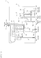
- FIG. 1 shows a schematic diagram of a heat exchange system 1 equipped with a heat exchanger 10 according to a preferred embodiment of the present invention.
- the heat exchange system 1 is used for heating medium fluid which is used for space heating and heating domestic water, while the heat exchange system 1 may be used only for heating the medium fluid for space heating or only for heating the domestic water.
- the heat exchange system 1 is mainly provided with the heat exchanger 10, a fan 2a, a burner 3, a siphon 4b, a pump 5a, a heat exchanger 6, and a housing 9.
- the heat exchange system 1 has a gas inlet connector 9a to which a fuel gas supply pipe (not shown) is connected, a condensate outlet connector 9b to which a drain outlet pipe (not shown) is connected, medium fluid water inlet/outlet connectors 9c, 9d to which medium fluid inlet/outlet pipes (not shown) are respectively connected, and DHW (domestic heat water) inlet/outlet connectors 9e, 9f to which DHW inlet/outlet pipes (not shown) are respectively connected.
- DHW domestic heat water
- the housing 9 shown in FIG. 1 has a box-like-shape such as a cuboid shape.
- the housing 9 accommodates the heat exchanger 10, the fan 2a, the burner 3, the siphon 4b, the pump 5a, and the heat exchanger 6 as shown in FIG. 1 .
- the fan 2a intakes a fuel gas, such as natural gas, supplied from the fuel gas supply pipe (not shown) via the gas inlet connector 9a and a gas pipe 2 as shown in FIG. 1 .
- the fan 2a also intakes air from the outside of the housing 9. The fan 2a then supplies the mixture gas with the fuel gas and the air to the burner 3.
- the burner 3 is mounted on the heat exchanger 10 as shown in FIG. 3 . Specifically, the burner 3 is mounted on the top of the heat exchanger 10. A burner port 3a of the burner 3, from which flammable gas is injected, is arranged in a combustion space 42 formed in the heat exchanger 10 as shown in FIG. 6 . The burner 3 injects the flammable gas (mixture gas with the fuel gas and the air) into the combustion space 42 and combusts the flammable gas in the combustion space 42.
- the flammable gas mixture gas with the fuel gas and the air
- the heat exchanger 10 has a flue gas space 40 including the combustion space 42 and two channels 60, 70 as shown in FIG. 5 .
- the heat exchanger 10 is configured such that the medium fluid in the two channels 60, 70 can exchange heat with the flue gas flowing in the flue gas space 40, in use.
- the burner port 3a of the burner 3 is arranged over the combustion space 42 and the flammable gas is combusted in the combustion space 42. Flue gas generated by the combustion of the flammable gas flows downward in the flue gas space 40.
- the channels 60, 70 constitute a part of a medium fluid circuit 5 in which a medium fluid circulates.
- the medium fluid circuit 5 further includes an inlet pipe 5b, an outlet pipe 5c, and the medium fluid inlet/outlet pipes (not shown) which are arranged outside the heat exchange system 1 and are connected to the medium fluid water inlet/outlet connectors 9c, 9d.
- the medium fluid circuit 5 also includes space heating devices (not shown), such as floor heating devices and radiators, which are arranged outside the heat exchange system 1 and which are connected to the medium fluid outlet pipe and the medium fluid inlet pipe.
- the medium fluid circulating in the medium fluid circuit 5 is an aqueous medium.
- the medium fluid is supplied to the medium fluid inlet connector 9c from the medium fluid inlet pipe (not shown).
- the medium fluid then flows in each of the channels 60, 70 from the inlet of each of the channels 60, 70 through the inlet pipe 5b.
- the pump 5a is arranged to circulate the medium fluid in the medium fluid circuit 5.
- the medium fluid flows in the channels 60, 70 and exchanges heat with the flue gas flowing in the flue gas space 40.
- the medium fluid in each of the channels 60, 70 flows out from an outlet of each of the channels 60, 70.
- the medium fluid then flows out to the medium fluid outlet pipe (not shown) through the outlet pipe 5c and the medium fluid outlet connector 9d and is sent to space heating devices (not shown) through the medium fluid outlet pipe.
- the drain collecting part 4 includes a drain pipe 4a.
- the end portion of the drain pipe 4a is connected to the siphon 4b.
- the siphon 4b allows the condensate from the flue gas to drain to the drain outlet pipe (not shown) which is connected to the condensate outlet connector 9b while preventing the release of the flue gas.
- the medium fluid circuit 5 includes a connecting pipe 5d which connects the inlet pipe 5b and the outlet pipe 5c of the medium fluid circuit 5 via a medium fluid channel 6a formed in the heat exchanger 6.
- the connecting pipe 5d is configured so that the medium fluid can flow from the outlet pipe 5c to the inlet pipe 5b through the medium fluid channel 6a.
- the heat exchanger 6 also has a domestic water channel 6b formed therein.
- An inlet pipe 7a of the domestic water is connected to an inlet of the domestic water channel 6b.
- An outlet pipe 7b of the domestic water is connected to an outlet of the domestic water channel 6b.
- the inlet pipe 7a of the domestic water is connected to DHW inlet connector 9e.
- the outlet pipe 7b of the domestic water is connected to DHW outlet connector 9f.
- the inlet/outlet pipes 7a, 7b of the domestic water are configured so that domestic water flows in the domestic water channel 6b from the inlet of the domestic water channel 6b, and flows out to the outlet pipe 7b from the outlet of the domestic water channel 6b after the domestic heat water passes through the domestic water channel 6b.
- domestic heat water flowing in domestic water channel 6b exchanges heat with the medium fluid flowing the medium fluid channel 6a, in use.
- Fuel gas is supplied via the gas inlet connector 9a. Fuel gas and air taken from the outside of the housing 9 are mixed. The mixture gas is supplied to the burner 3. The flammable gas (mixture gas) is injected into the combustion space 42 from the burner 3 and is combusted in the combustion space 42. Flue gas then flows downwardly in the flue gas space 40.
- Medium fluid is circulated in the medium fluid circuit 5.
- relatively low temperature medium fluid flows into the channels 60, 70 via medium fluid inlet connector 9c and the inlet pipe 5b.
- Medium fluid flowing in the channels 60, 70 exchanges heat with the flue gas in the flue gas space 40 in use.
- the medium fluid heated at the heat exchanger 10 flows out from the medium fluid outlet connector 9d through the outlet pipe 5c and is sent to the space heating devices (not shown).
- the heat of the medium fluid is used for the space heating devices and cooled medium fluid (the medium fluid taken its heat by the space heating devices) then returns to the heat exchange system 1.
- the medium fluid heated at the heat exchanger 10 is sent to the heat exchanger 6 to heat the domestic water.
- the heated domestic water is sent to the usage point such as bath room and kitchen.
- the flue gas flowing out of the flue gas space 40 is exhausted through the gas duct 8.
- the condensate from the flue gas is drained to the drain outlet pipe through the siphon 4b.
- a heat exchanger 10 according to a preferred embodiment of the present invention will be described in detail.
- FIG. 2 shows a perspective view of the heat exchanger 10.
- FIG. 3 shows a side view of the heat exchanger 10 on which the burner is mounted.
- FIG. 4 shows a front view of the heat exchanger 10.
- the heat exchanger 10 is preferably manufactured by corrosion resistant metal such as aluminum alloy.
- heat exchanger 10 is manufactured as monoblock sand-cast, although manufacturing method is not limited to this.
- the heat exchanger 10 is designed so that the burner 3 is mounted on the top of the heat exchanger 10 as shown in FIG. 3 .
- the heat exchanger 10 mainly includes a front wall 20, a back wall 30, side walls 50, an inlet distribution pipe 52, and an outlet converging pipe 54 as shown in FIG.2 .
- the front wall 20 and the back wall 30 form a flue gas space 40 for a flue gas.
- the flue gas space 40 is formed by a space defined by the front wall 20, the back wall 30 and the side walls 50 which are attached to lateral ends of the front wall 20 and the back wall 30.
- the flue gas space 40 includes the combustion space 42 of the flammable gas.
- the combustion space 42 in which the burner port 3a of the burner 3 is installed, is arranged at the upper part of the flue gas space 40 as shown in FIG. 5 .
- the flue gas flows downwardly in the flue gas space 40 from the combustion space 42 and flows out from an opening 44 arranged at the bottom of the heat exchanger 10, in use.
- a front channel 60 is formed in the front wall 20 and a back channel 70 is formed in the back wall 30 as shown in FIG.5 .
- the medium fluid flows in the front channel 60 and back channel 70, in use.
- the inlet distribution pipe 52 has a tube-shape which has an inlet opening 52a in the front side as shown in FIG. 4 .
- the inlet pipe 5b of the medium fluid circuit 5 is connected at the inlet opening 52a.
- the inlet distribution pipe 52 is also connected to the inlets of each of the front channel 60 and the back channel 70.
- the inlet distribution pipe 52 is configured to distribute the fluid to the front channel 60 and the back channel 70, in use.
- the medium fluid flows into the front channel 60 and the back channel 70 through the inlet distribution pipe 52, in use.
- the outlet converging pipe 54 has a tube-shape which has an outlet opening 54a in the front side as shown in FIG. 4 .
- the outlet pipe 5c of the medium fluid circuit 5 is connected at the outlet opening 54a.
- the outlet converging pipe 54 is also connected to the outlets of each of the front channel 60 and the back channel 70.
- the outlet converging pipe 54 is configured to converge the fluid from the front channel 60 and the back channel 70, and output therefrom, in use.
- the converged medium fluid flows in the outlet pipe 5c of the medium fluid circuit 5, in use.
- the back wall 30 has a tabular shape.
- the back wall 30 extends along a first plane P1 as shown in FIG. 5 .
- the heat exchanger 10 is arranged on a horizontal plane and the first plane P1 is a vertical plane in this embodiment, although the arrangement of the heat exchanger 10 is not limited to this.
- the heat exchanger 10 is preferably accommodated such that the back wall 30 extends along one of the walls of the housing 9. Due to the shape of the back wall 30, a dead space between the back surface of the heat exchanger 10 and the inner surface of the wall of the housing 9 can be minimized.
- the front wall 20 includes a lower portion 22 and an upper portion 24 as shown in FIG. 2 .
- the lower portion 22 extends upwardly along the back wall 30 as shown in FIG. 3 .
- the lower portion 22 of the frond wall extends in parallel with the back wall 30.
- the lower portion 22 preferably has a plane-like shape.
- the upper portion 24 extends upwardly from the upper end of the lower portion 22 as shown in FIG. 3 . More specifically, the upper portion 24 extends upwardly from the upper end of the lower portion 22 in a planar fashion.
- the upper portion 24 of the front wall 20 has a plane-like shape.
- the upper portion 24 extends outwardly away from the back wall 30 so as to form a combustion space 42 of a flammable gas between the upper portion 24 of the front wall 20 and the back wall 30.
- the length L2 of the upper portion 24 along the longitudinal direction thereof is preferably longer than the length L1 of the lower portion 22 along the longitudinal direction thereof as shown in FIG. 3 .
- Each of the longitudinal direction of the upper portion 24 and the lower portion 22 is a direction along which each of the upper portion 24 and the lower portion 22 extends in side view.
- the space formed under the upper portion 24 is effectively used for arranging elements of the heat exchange system 1 such as the fan 2a to achieve the downsizing of the housing 9 of the heat exchange system 1 as shown in FIG. 3 .
- the space formed under the upper portion 24 may also be used for arranging the other elements of the heat exchange system 1 such as valve, pipe, and venturi device.
- the inner surface of the upper portion 24 is a surface which faces the back wall 30.
- the inner surface of the back wall 30 is a surface which faces the front wall 20.
- FIG. 5 is a cross section view of the heat exchanger viewing from the arrow direction of the V-V line of FIG.4 .
- FIG. 6 is a cross section view of the heat exchanger viewing from the arrow direction of the VI-VI line of FIG.4 .
- FIG. 7 is a cross section view of the heat exchanger viewing from the arrow direction of the VII-VII line of FIG.3 .
- the upper portion 24 of the front wall 20 is provided with front fins 110 as shown in FIG. 5 .
- the front fins 110 are formed to protrude from the inner surface of the front wall 20.
- a plurality of the front fins 110 is arranged along the lateral direction (left-right direction) of the front wall 20 on the inner surface of the upper portion 24 at a predetermined interval.
- the number of the front fins 110 and the interval between the front fins 110 depend on the various factors such as the amount of heat transferred from the flue gas to the medium fluid, materials of the walls, and the power of the burner to be installed.
- the front wall 20 is provided with front pins 130, 150 as shown in FIG. 5 .
- the front pins 130, 150 are arranged on the downstream side of the front fins 110 with respect to the flue gas flow direction. In other words, the front pins 130, 150 are arranged below the front fins 110.
- the cross-sectional of the front pins 130, 150 with respect to its main axis has a circular shape, or preferably an elliptic shape which is longer in the longitudinal direction than the lateral direction of the front wall.
- Each of the pins 130, 150 has larger surface area per unit volume than the front fins 110.
- the front pins 130, 150 extend backwardly from the inner surface of the front wall 20.
- a part of the front pins is arranged at the upper portion 24 of the front wall 20 below the front fins 110.
- a plurality of the front pins 130 is preferably arranged along the lateral direction (left-right direction) of the front wall 20 on the inner surface of the upper portion 24 at a predetermined interval.
- Several lines of the front pins 130 are preferably arranged at the upper portion 24 along the longitudinal direction at a predetermined interval.
- the rest of the front pins 150 are arranged at the lower portion 22 of the front wall.
- a plurality of the front pins 150 is arranged along the lateral direction (left-right direction) of the front wall 20 on the inner surface of the lower portion 22 at a predetermined interval.
- Several lines of the front pins 150 are arranged at the lower portion 22 along the longitudinal direction at a predetermined interval.
- the number of the front pins 130, 150, and the interval between the front pins 130, 150 depend on the various factors such as the amount of heat transferred from the flue gas to the medium fluid, materials of the walls, and the power of the burner to be installed.
- the back wall 30 is provided with back fins 120 as shown in FIG. 5 .
- the back fins 120 are formed to protrude from the inner surface of the back wall 30.
- a plurality of the back fins 120 is arranged along the lateral direction (left-right direction) of the back wall 30 on the inner surface of the back wall 30 at a predetermined interval as shown in FIG. 7 .
- the number of the back fins 120 and the interval between the back fins 120 depend on the various factors such as the amount of heat transferred from the flue gas to the medium fluid, materials of the walls, and the power of the burner to be installed.
- the number of the back fins 120 and the interval between the back fins 120 are preferably the same as those of the front fins 110.
- Each of the back fins 120 preferably corresponds to one of the front fins 110 such that the corresponding front and back fins face to each other.
- the front fin 110 and the corresponding back fin 120 are arranged symmetrically with respect to a virtual line C2 along which the flammable gas is to be injected into the combustion space 42 as shown in FIG. 5 .
- the shapes of the front fins 110 and the back fins 120 are described in detail with reference to FIG. 6 .
- the height H1 of the first portion 112, 122 from the inner surface of the corresponding wall 20, 30 is smaller than the height H2 of the second portion 114, 124 from the inner surface of the corresponding wall 20, 30 as shown in FIG.6 .
- each of the fins 110, 120 includes the first portion 112, 122 and the second portion 114, 124.
- Most of the front fins 110 and the corresponding back fins 120, except for fins 110, 120 arrange under the outlet converging pipe 54 include an inwardly bulged portion 112a, 122a which bulges toward the virtual line C2 and an outwardly curved portion 112b, 122b which curves away from the virtual line C2 as shown in FIG. 6 .
- the outwardly curved portion 112b, 122b is arranged below the inwardly bulged portion 112a, 122a as shown in FIG.6 .
- the inwardly bulged portion 112a, 122a and the outwardly curved portion 112b, 122b are formed so as to keep a predetermined distance between the burner 3, more specifically the burner port 3a of the burner 3, to be installed on the heat exchanger 10 and the fin 110, 120.
- the predetermined distance depends on various factors such as the desired power of the burner 3 and the material of the fins 110, 120.
- each of the fins 110, 120 includes the inwardly bulged portion 112a, 122a and the outwardly curved portion 112b, 122b.
- the tapered portion 112c, 122c is formed so as to keep a predetermined distance between the burner 3, more specifically the burner port 3a of the burner 3, to be installed in the heat exchanger 10 and the fin 110, 120.
- the predetermined distance depends on various factors such as the desired power of the burner 3 and the material of the fins 110, 120.
- each of the fins 110, 120 has the tapered portion 112c, 122c.
- the back wall 30 is provided with back pins 140, 150 as shown in FIG. 5 .
- the cross-sectional of the back pins 140, 150 with respect to its main axis has a circular shape, or preferably an elliptic shape which is longer in the longitudinal direction than the lateral direction of the back wall 30.
- Each of the pins 140, 150 has larger surface area per unit volume than the back fins 120.
- the back pins 140, 150 extends forwardly from the inner surface of the back wall 30.
- a plurality of the back pins 140, 150 is arranged in the lateral direction (left-right direction) of the back wall 30 on the inner surface of the back wall 30 at a predetermined interval.
- back pins 140, 150 are arranged on the back wall 30 along the longitudinal direction at a predetermined interval.
- the number of the back pins 140, 150 and the interval between the back pins 140, 150 depend on the various factors such as the amount of heat transferred from the flue gas to the medium fluid, materials of the walls, and the power of the burner to be installed.
- the front pins 150 arranged at the lower portion 22 of the front wall 20 are preferably connected to the corresponding back pins 150.
- each of the pins 150 extends from the front wall 20 to the back wall 30.
- front pins 150 arranged at the lower portion 22 of the front wall 20 are integrated with the back pins 150.
- the front pins 130 arranged at the upper portion 24 of the front wall 20 so as to face to the corresponding back pins 140.
- the front pins 130 are arranged at the upper portion 24 of the front wall 20 is not connected to the corresponding the back pins 140 so as to make a space between them.
- the upper portion of the front wall 20 and the corresponding part of the back wall 30, which forms the combustion space 42 of heat exchanger 10 therebetween, is designed symmetrically with respect to the virtual line C2 which tilts against a virtual line C1.
- the lower portion 22 of the front wall 20 and the back wall 30 is arranged symmetrical with respect to the virtual line C1.
- FIG. 8 is a cross section view of the heat exchanger viewing from the arrow direction of the VIII-VIII line of FIG.3 .
- the front wall 20 has an inside wall 602 and an outside wall 604 which face to each other and form the front channel 60 therebetween.
- the front wall 20 also has wall elements 606 which connect the inside wall 602 and the outside wall 604 and define the front channel 60.
- the back wall 30 has an inside wall 702 and an outside wall 704 which face to each other and form the back channel 70 therebetween.
- the back wall 30 has wall elements 706 which connect the inside wall 702 and outside wall 704 and define the back channel 70.
- the front channel 60 includes straight portions 60a, 60b, 60c, 60d, 60e, 60f, 60g, 60h, and 60i which are arranged in substantially parallel to each other and are connected in series as shown in FIG. 8 .
- the medium fluid supplied from the inlet of the front channel 60 flows the straight portions 60a, 60b, 60c, 60d, 60e, 60f, 60g, 60h, and 60i in this order and flows out from the outlet of the front channel 60.
- parallel means that the two straight portions are connected with an angle such that the speed of the turning fluid in the channel drops to nearly zero on the inner side in the connecting area 61 a, 61 b, 61 c, 61 d, 61 e, 61 f, 61 g, and 61 h.
- the fluid nearly stops upon turning.
- a plurality of pins 62 extending from the inside wall 602 is arranged in the straight portions 60a, 60b so as to improve the heat transfer efficiency between the medium fluid flowing in the straight portions 60a, 60b and the flue gas which flows along the inside wall 602.
- the straight portions 60a, 60b require higher strength against burst than the straight portions 60c-60i since the straight portions 60a, 60b has the larger surface area compared with the straight portions 60c-60i.
- a plurality of pins 62 can also improve the strength against burst of the straight portions 60a, 60b.
- a plurality of grooves 68 extending along the longitudinal direction of the straight portions 60c-60i is formed on the inside wall 602. Thereby the heat transfer area is increased between the medium fluid flowing in the straight portions 60c-60i and the flue gas which flows along the inside wall 602.
- the cross-sectional area of the straight portion 60a arranged on the most upstream side is larger than the cross-sectional area of the other straight portions 60b-60i arranged on downstream side with respect to the fluid flow as shown in FIG. 5 .
- the back channel 70 also includes straight portions 70a, 70b, 70c, 70d, 70e, 70f, 70g, 70h, and 70i as shown in FIG. 5 .
- the straight portions 70a-70i are arranged in substantially parallel to each other and are connected in series.
- the medium fluid flowing from the inlet of the back channel 70 flows the straight portions 70a, 70b, 70c, 70d, 70e, 70f, 70g, 70h, and 70i in this order and flows out from the outlet of the back channel 70.
- parallel has the same meaning with the previous paragraph for the front channel 60.
- a plurality of pins (not shown) extending from the inside wall 702 is arranged in the straight portions 70a, 70b and a plurality of grooves 78 extending along the longitudinal direction of the straight portions 70c-70i are formed on the inside wall 702 in the straight portions 70c-70i.
- the cross-sectional area of the straight portion 70a arranged on the most upstream side is larger than the cross-sectional area of the other straight portions 70b-70i arranged on downstream side with respect to the fluid flow.
- the front channel 60 is further explained with reference to FIG. 8 .
- stagnation prevention means 64, 66 are arranged in each of the connecting area 61 a-61 h of the straight portions 60a-60i, but it is not limited to this configuration. It is preferable that at least the first stagnation prevention means 64 is arranged in the connecting area 61 a of the straight portions 60a and the straight portion 60b which locates on the most upstream side in the channel 60 with respect to a fluid flow.
- the first stagnation prevention means 64 is arranged in the connecting area 61 a of the straight portions 60a and the straight portion 60b which locates on the most upstream side in the channel 60 with respect to the fluid flow.
- the first stagnation prevention means 64 is arranged in the vicinity of the inner part T1 of the joint 60ab of the straight portions 60a, 60b around which the fluid is to turn as shown in FIG. 8 .
- the first stagnation prevention means 64 is formed in a hook-like shape when seen from the direction perpendicular to the front wall 20 as shown in FIG. 8 .
- At least one or more second stagnation prevention means 66 are preferably arranged in the connecting area 61b-61h of the straight portions 60b-60i in the channel 60.
- the second stagnation prevention means 66 are arranged in the connecting areas other than the connecting area 61 a which locates on the most upstream side in the channel 60 with respect to the fluid flow.
- the second stagnation prevention means 66 are formed in an arc-like shape when seen from the direction perpendicular to the front wall 20 as shown in FIG. 8 .
- the arc-like shaped second stagnation prevention means 66 are arranged in the front channel 60 such that the arc-like shaped surface is substantially along the fluid flow.
- Each of the second stagnation prevention means 66 is arranged in the vicinity of an inner part of a joint of the straight portions 60b-60i around which the fluid is to turn.
- one of the second stagnation prevention means 66 is arranged in the vicinity of an inner part T2 of a joint 60bc of the straight portions 60b, 60c around which the fluid is to turn as shown in FIG. 8 .
- the first stagnation prevention means 64 is arranged so as to partially surround the inner part T1 of the joint 60ab of the straight portions 60a, 60b around which the fluid is to turn when seen from the direction perpendicular to the wall 20 as shown in FIG. 8 .
- the first stagnation prevention means 64 is preferably arranged so as to surround the inner part T1 of the joint 60ab of the straight portions 60a, 60b over an angle range of more than 90 degrees, and more preferably over an angle range of more than 180 degrees when seen from the direction perpendicular to the wall 20 as shown in FIG. 8 .
- the one or more second stagnation prevention means 66 are also arranged so as to partially surround the inner part of the joint of the straight portions around which the fluid is to turn when seen from the direction perpendicular to the wall 20 as shown in FIG. 8 .
- the second stagnation prevention means 66 are arranged so as to partially surround the inner part T2 of the joint 60bc of the straight portions 60b, 60c around which the fluid is to turn when seen from the direction perpendicular to the wall 20 as shown in FIG. 8 .
- the second stagnation prevention means 66 are arranged so as to surround the inner part T2 of the joint 60bc of the straight portions 60b, 60c over an angle range of more than 90 degrees when seen from the direction perpendicular to the wall 20.
- the wall elements 606 which connects the inside wall 602 and the outside wall 604 include extending wall elements W1, W2 which respectively extend along the main axis A1, A2 of the straight portion 60a, 60b.
- the wall elements W1, W2 extend from the inner part T1 of the joint 60ab of the straight portions 60a, 60b around which the fluid is to turn as shown in FIG. 9 .
- the main axes A1, A2 are axes along which the straight area of the straight portion 60a, 60b extends.
- the first stagnation prevention means 64 includes a first portion 64a which is arranged on the upstream side and a second portion 64b which is arranged on the downstream side with respect to the fluid flow as shown in FIG. 9 .
- a maximum distance D1 between the second portion 64b and the extending wall element W2 is shorter than a maximum distance D2 between the first portion 64a and the extending wall element W2.
- the distance between the second portion 64b and the extending wall element W2 may be almost equal at any points.
- the first stagnation prevention means 64 is arranged in the connecting area 61 a in the straight portion 60b which is located on the downstream side among the two straight portions 60a, 60b connected.
- Each of the straight portions 60a, 60b has a straight area which has a straight tube-like shape.
- the first stagnation prevention means 64 is arranged to extend from the connecting area 61 a into part of the straight area in the straight portion 60b.
- the first stagnation prevention means 64 may extend into the connecting area 61 a located in the straight portion 60a at the upstream side with respect to the fluid flow.
- the second stagnation prevention means 66 are arranged in the straight portion which is located at the downstream side with respect to the fluid flow among the straight portions connected. More specifically, the second stagnation prevention means 66 are arranged in the connecting area in the straight portion which is located on the downstream side among the two straight portions connected. Each of the straight portions 60c-60i has a straight area which has a straight tube-like shape. The second stagnation prevention means 66 may be arranged to extend from a connecting area into the straight area of the straight portion located on the downstream side.
- the front channel 60 is explained above in detail with reference to FIG. 8 .
- the explanation of the back channel 70 is omitted regarding the common feature between the front channel 60 and the back channel 70. Only the difference between the front channel 60 and the back channel 70 will be explained below.
- the heat exchanger 10 is therefore configured such that the volume flow rate and/or mass flow rate of the fluid in the front channel 60 is greater than the back channel 70, in use. It is preferable that the heat exchanger 10 is configured such that at least the mass flow rate of the fluid in the front channel 60 is greater than the back channel 70, in use.
- Volume flow rate means the volume of fluid which passes per unit time. Mass flow rate means mass of a fluid which passes per unit of time.
- the volume flow rate and mass flow rate of the fluid in the front channel 60 is greater than the back channel 70 means that the average volume flow rate and average mass flow rate of the fluid in the front channel 60 is greater than the back channel 70.
- Average volume/mass flow rate means volume/mass flow over the entire front or back channel 60, 70. Volume/mass flow rate is generally measured at the inlet/outlet of each channel 60, 70.
- the back channel 70 is configured to have a higher fluid resistance than the front channel 60.
- the minimum cross section in the back channel 70 is smaller than the minimum cross section in the front channel 60 with respect to cross sections intersecting with the direction of the fluid flow.
- an average cross-sectional area of the back channel 70 is smaller than the an average cross-sectional area of the front channel 60 with respect to cross sections intersecting with the direction of the fluid flow.
- the front channel 60 includes a plurality of the straight portions 60a-60i as front sub channels which are arranged in substantially parallel to each other and are connected in series.
- the back channel 70 includes a plurality of the straight portions 70a-70i as back sub channels which are arranged in substantially parallel to each other.
- the straight portions 70a-70i are connected in series, and each of which faces to one of the straight portions 60a-60i. With respect to cross sections intersecting with the direction of the fluid flow, at least one of the straight portions 70a-70i has a minimum cross section smaller than a minimum cross section of the corresponding straight portions 60a-60i and/or an average cross-sectional area smaller than an average cross-sectional area of the corresponding straight portions 60a-60i.
- each of the straight portions 70a-70i has a minimum cross section smaller than a minimum cross section of the corresponding straight portions 60a-60i and/or an average cross-sectional area smaller than an average cross-sectional area of the corresponding straight portions 60a-60i.
- the volume of the entire back channel 70 is smaller than the volume of the entire front channel 60.
Landscapes
- Engineering & Computer Science (AREA)
- Physics & Mathematics (AREA)
- Thermal Sciences (AREA)
- Mechanical Engineering (AREA)
- General Engineering & Computer Science (AREA)
- Chemical & Material Sciences (AREA)
- Combustion & Propulsion (AREA)
- Heat-Exchange Devices With Radiators And Conduit Assemblies (AREA)
Abstract
Description
- The invention relates to a heat exchanger, especially a heat exchanger in which heat is transferred from a flue gas to a flowing liquid.
- Such a heat exchanger is known from
WO 2009/053248 . This heat exchanger is provided with a front wall and a back wall. A combustion space is formed in the upper part of the space between the front wall and the back wall. Flammable gas is injected and combusted by a burner mounted on a top of the heat exchanger. Channels in which water flows are respectively formed in the front wall and the back wall. Heat generated by gas combustion is transferred to water flowing in the channels. The walls are arranged symmetrically with respect to the center line in side view. In the heat exchanger, since the walls are arranged symmetrically, the fluid flowing both of the channels is heated almost equally when the channels are equally designed. - The known heat exchanger mentioned above has certain efficiency in heat exchange, although further improvement is required in aspect of downsizing a system equipped with the heat exchanger. However, if the arrangement of the walls is changed for downsizing the system equipped with the heat exchanger, there is a possibility that the fluid flowing through both of the channels is heated unequally even though the channels are symmetrically designed. The heat exchange efficiency is thereby deteriorated.
- It is the object of the present invention to provide a heat exchanger which contributes to the miniaturization of the system equipped with the heat exchanger while maintaining heat exchange efficiency.
- A first aspect of the present invention provides a heat exchanger comprising a front wall and a back wall to form a space for a flue gas, and a front channel and a back channel formed in the front wall and the back wall, respectively, in which a fluid is to flow. The heat exchanger is configured such that the fluid in the front and back channels can exchange heat with the flue gas, in use. The entire back wall extends along a first plane. The front wall includes a lower portion and an upper portion. The lower portion extends upwardly along the back wall. The upper portion extends upwardly from the upper end of the lower portion and extends outwardly away from the back wall so as to form a combustion space of a flammable gas between the upper portion and the back wall. The heat exchanger is further configured such that the volume flow rate and/or mass flow rate of the fluid in the front channel is greater than the back channel, in use.
- Volume flow rate means the volume of fluid which passes per unit time. Mass flow rate means mass of a fluid which passes per unit of time.
- "The volume flow rate and/or mass flow rate of the fluid in the front channel is greater than the back channel" means that the average volume flow rate and/or average mass flow rate of the fluid in the front channel is greater than the back channel. Average volume/mass flow rate means volume/mass flow over the entire front or back channel.
- Volume/mass flow rate is generally measured at the inlet/outlet of each channel.
- With this configuration mentioned above, the heat exchanger can contribute the downsizing of a heat exchanging system accommodated in a housing and equipped with the heat exchanger. This is because the back wall extending along the first plane without extending outwardly can minimize a useless space between the heat exchanger and the housing.
- The heat transfers on the front wall side and back wall side have different characteristic because of the unsymmetrical design of the walls. Specifically, the fluid in the front channel of the front wall can obtain more heat from the flue gas than the fluid in the back channel of the back wall. The volume flow rate or mass flow rate of the fluid is adjusted to be different on each side. Thereby the temperature of the fluid at the outlet of each channel can reach to substantially the same temperature.
- In this way, high space efficiency and high heat exchange efficiency can be achieved.
- According to a preferred embodiment of the heat exchanger mentioned above, the back channel is configured to have a higher fluid resistance than the front channel.
- With the above configuration, it is possible to adjust the volume flow rate and/or mass flow rate of the fluid in the front channel greater than the back channel.
- According to another preferred embodiment of any one of the heat exchangers mentioned above, a minimum cross section in the back channel is smaller than the minimum cross section in the front channel with respect to cross sections intersecting with the direction of the fluid flow.
- With the above configuration, the heat exchanger is configured so that the back channel has a higher fluid resistance than the front channel. It is therefore possible to adjust the volume flow rate and/or mass flow rate of the fluid in the front channel greater than the back channel.
- According to a preferred embodiment of any one of the heat exchangers mentioned above, an average cross-sectional area of the back channel is smaller than the an average cross-sectional area of the front channel with respect to cross sections intersecting with the direction of the fluid flow.
- With the above configuration, the higher fluid resistances in the front and back channels are controlled by adjusting the average cross-sectional areas of the front and back channels. It is therefore possible to adjust the volume flow rate and/or mass flow rate of the fluid in the front channel greater than the back channel in a more accurate manner.
- According to a preferred embodiment of any one of the heat exchangers mentioned above, the front channel includes a plurality of front sub channels which are arranged in substantially parallel to each other and are connected in series. The back channel includes a plurality of back sub channels which are arranged in substantially parallel to each other. The back sub channels are connected in series, and each of which faces to one of the first sub channels. With respect to cross sections intersecting with the direction of the fluid flow, at least one of the back sub channel has the minimum cross section smaller than the minimum cross section of the corresponding front sub channel, and/or an average cross-sectional area smaller than an average cross-sectional area of the corresponding front sub channel.
- With the above configuration, it is therefore possible to adjust the volume flow rate and/or mass flow rate of the fluid in the front channel greater than the back channel in a more accurate manner.
- According to a preferred embodiment of any one of the heat exchangers with the front channel including a plurality of the front sub channels and the back channel including a plurality of the back sub channels mentioned above, with respect to cross sections intersecting with the direction of the fluid flow, each of the back sub channels has the minimum cross section smaller than the minimum cross section of the corresponding front sub channel, and/or an average cross-sectional area smaller than an average cross-sectional area of the corresponding front sub channel.
- With the above configuration, it is therefore possible to adjust the volume flow rate and/or mass flow rate of the fluid in the front channel greater than the back channel in a more accurate manner.
- According to a preferred embodiment of any one of the heat exchangers mentioned above, the volume of the entire back channel is smaller than the volume of the entire front channel.
- With the above configuration, it is therefore possible to adjust the volume flow rate and/or mass flow rate of the fluid in the front channel greater than the back channel in a more accurate manner.
- According to a preferred embodiment of any one of the heat exchangers mentioned above, a flow suppression means is arranged in the back channel.
- In general, it is preferable to reduce the fluid resistance of the channel in view of reducing the energy necessary for flowing the fluid. However, in this configuration, a flow suppression mean is provided in the back channel to adjust the volume flow rate and/or mass flow rate of the fluid in the front channel greater than the back channel so as to maintain the high heat exchange efficiency.
- Examples of such a flow suppression means are obstacles arranged in the back channel such as protrusions extending from the walls forming the back channel.
- According to a preferred embodiment of any one of the heat exchangers mentioned above, the heat exchanger further comprises a distribution mechanism connected to the inlets of each of the front channel and the back channel. The distribution mechanism is configured to distribute the fluid to the front channel and the back channel, in use. The distribution mechanism is further configured to distribute more fluid to the front channel than to the back channel.
- With the above configuration, it is possible to adjust the volume flow rate and/or mass flow rate of the fluid in the front channel greater than the back channel by providing more fluid to the front channel.
- According to a preferred embodiment of any one of the heat exchangers mentioned above, the heat exchanger further comprises a converging mechanism connected to the outlets of each of the front channel and the back channel. The converging mechanism is configured to converge the fluid from the front channel and the back channel and output therefrom, in use. The converging mechanism is configured to control the fluid resistance of the fluid flowing from the back channel higher than the fluid resistance of the fluid flowing from the front channel, in use.
- With the above configuration, it is possible to adjust the volume flow rate and/or mass flow rate of the fluid in the front channel greater than the back channel in an easier manner.
- According to a preferred embodiment any one of the heat exchangers mentioned above, the heat exchanger is configured such that the temperature of the fluid at each outlet of each channel is substantially the same, in use.
- With the above configuration, the volume flow rate and/or mass flow rate of the fluid in the front channel is controlled so that the temperature of the fluid at each outlet of each channel is adjusted substantially the same. As a result, high heat exchange efficiency can be achieved.
-
-
FIG. 1 is a schematic diagram of the heat exchange system equipped with the heat exchanger according to an embodiment of the present invention; -
FIG. 2 is a perspective view of the heat exchanger according toFIG. 1 ; -
FIG. 3 is a side view of the heat exchanger on which the burner is mounted according toFIG. 1 ; -
FIG. 4 is a front view of the heat exchanger according toFIG. 1 ; -
FIG. 5 is a cross section view of the heat exchanger viewing from the arrow direction of the V-V line ofFIG.4 ; -
FIG. 6 is a cross section view of the heat exchanger viewing from the arrow direction of the VI-VI line ofFIG.4 ; -
FIG. 7 is a cross section view of the heat exchanger viewing from the arrow direction of the VII-VII line ofFIG.3 ; -
FIG. 8 is a cross section view of the heat exchanger viewing from the arrow direction of the VIII-VIII line ofFIG.3 ; -
FIG. 9 is a partial enlarged view ofFIG. 8 ; -
Fig. 10 is a schematic diagram of the heat exchanger according to another embodiment of the present invention; -
Fig. 11 is a schematic diagram of the heat exchanger according to another embodiment of the present invention; and -
Fig. 12 is a schematic diagram of the heat exchanger according to another embodiment of the present invention. - Preferred embodiments of the heat exchanger according to the present invention will be described with reference to the drawings.
- It should be understood that the detailed explanation are provided merely for the purpose of explanation, and are in no way to be construed as limiting of the present invention. While the present invention will be described with reference to exemplary preferred embodiments, it is understood that the words which have been used herein are words of description and illustration, rather than words of limitation. Changes may be made, within the purview of the appended claims, as presently stated and as amended, without departing from the scope and spirit of the present invention in its aspects. Although the present invention will be described herein with reference to preferred structures, materials and embodiments, the present invention is not intended to be limited to the particulars disclosed herein; rather, the present invention extends to all functionally equivalent structures, methods and uses, such as are within the scope of the appended claims.
-
FIG. 1 shows a schematic diagram of aheat exchange system 1 equipped with aheat exchanger 10 according to a preferred embodiment of the present invention. - The
heat exchange system 1 is used for heating medium fluid which is used for space heating and heating domestic water, while theheat exchange system 1 may be used only for heating the medium fluid for space heating or only for heating the domestic water. - As shown in
FIG. 1 , theheat exchange system 1 is mainly provided with theheat exchanger 10, afan 2a, aburner 3, a siphon 4b, apump 5a, a heat exchanger 6, and ahousing 9. As shown inFIG. 1 , theheat exchange system 1 has agas inlet connector 9a to which a fuel gas supply pipe (not shown) is connected, acondensate outlet connector 9b to which a drain outlet pipe (not shown) is connected, medium fluid water inlet/outlet connectors outlet connectors - The
housing 9 shown inFIG. 1 has a box-like-shape such as a cuboid shape. Thehousing 9 accommodates theheat exchanger 10, thefan 2a, theburner 3, the siphon 4b, thepump 5a, and the heat exchanger 6 as shown inFIG. 1 . - The
fan 2a intakes a fuel gas, such as natural gas, supplied from the fuel gas supply pipe (not shown) via thegas inlet connector 9a and agas pipe 2 as shown inFIG. 1 . Thefan 2a also intakes air from the outside of thehousing 9. Thefan 2a then supplies the mixture gas with the fuel gas and the air to theburner 3. - The
burner 3 is mounted on theheat exchanger 10 as shown inFIG. 3 . Specifically, theburner 3 is mounted on the top of theheat exchanger 10. A burner port 3a of theburner 3, from which flammable gas is injected, is arranged in acombustion space 42 formed in theheat exchanger 10 as shown inFIG. 6 . Theburner 3 injects the flammable gas (mixture gas with the fuel gas and the air) into thecombustion space 42 and combusts the flammable gas in thecombustion space 42. - The
heat exchanger 10 has aflue gas space 40 including thecombustion space 42 and twochannels FIG. 5 . Theheat exchanger 10 is configured such that the medium fluid in the twochannels flue gas space 40, in use. - As mentioned above, the burner port 3a of the
burner 3 is arranged over thecombustion space 42 and the flammable gas is combusted in thecombustion space 42. Flue gas generated by the combustion of the flammable gas flows downward in theflue gas space 40. - The
channels inlet pipe 5b, anoutlet pipe 5c, and the medium fluid inlet/outlet pipes (not shown) which are arranged outside theheat exchange system 1 and are connected to the medium fluid water inlet/outlet connectors heat exchange system 1 and which are connected to the medium fluid outlet pipe and the medium fluid inlet pipe. For example, the medium fluid circulating in the medium fluid circuit 5 is an aqueous medium. - In the medium fluid circuit 5, the medium fluid is supplied to the medium
fluid inlet connector 9c from the medium fluid inlet pipe (not shown). The medium fluid then flows in each of thechannels channels inlet pipe 5b. On theinlet pipe 5b, thepump 5a is arranged to circulate the medium fluid in the medium fluid circuit 5. In theheat exchanger 10, the medium fluid flows in thechannels flue gas space 40. After passing through thechannels channels channels outlet pipe 5c and the mediumfluid outlet connector 9d and is sent to space heating devices (not shown) through the medium fluid outlet pipe. - The configuration of the
heat exchanger 10 will be explained in detail later. - After the flue gas has passed through the
flue gas space 40, the flue gas is exhausted out of thehousing 9 though agas duct 8. Condensate from the flue gas is corrected at adrain collecting part 4 located below theheat exchanger 10. Thedrain collecting part 4 includes adrain pipe 4a. The end portion of thedrain pipe 4a is connected to the siphon 4b. The siphon 4b allows the condensate from the flue gas to drain to the drain outlet pipe (not shown) which is connected to thecondensate outlet connector 9b while preventing the release of the flue gas. - The medium fluid circuit 5 includes a connecting
pipe 5d which connects theinlet pipe 5b and theoutlet pipe 5c of the medium fluid circuit 5 via a mediumfluid channel 6a formed in the heat exchanger 6. The connectingpipe 5d is configured so that the medium fluid can flow from theoutlet pipe 5c to theinlet pipe 5b through the mediumfluid channel 6a. - The heat exchanger 6 also has a
domestic water channel 6b formed therein. Aninlet pipe 7a of the domestic water is connected to an inlet of thedomestic water channel 6b. Anoutlet pipe 7b of the domestic water is connected to an outlet of thedomestic water channel 6b. Theinlet pipe 7a of the domestic water is connected toDHW inlet connector 9e. Theoutlet pipe 7b of the domestic water is connected toDHW outlet connector 9f. The inlet/outlet pipes domestic water channel 6b from the inlet of thedomestic water channel 6b, and flows out to theoutlet pipe 7b from the outlet of thedomestic water channel 6b after the domestic heat water passes through thedomestic water channel 6b. In the heat exchanger 6, domestic heat water flowing indomestic water channel 6b exchanges heat with the medium fluid flowing the mediumfluid channel 6a, in use. - The operation of the
heat exchange system 1 is briefly explained. - Fuel gas is supplied via the
gas inlet connector 9a. Fuel gas and air taken from the outside of thehousing 9 are mixed. The mixture gas is supplied to theburner 3. The flammable gas (mixture gas) is injected into thecombustion space 42 from theburner 3 and is combusted in thecombustion space 42. Flue gas then flows downwardly in theflue gas space 40. - Medium fluid is circulated in the medium fluid circuit 5. During circulation, relatively low temperature medium fluid flows into the
channels fluid inlet connector 9c and theinlet pipe 5b. Medium fluid flowing in thechannels flue gas space 40 in use. The medium fluid heated at theheat exchanger 10 flows out from the mediumfluid outlet connector 9d through theoutlet pipe 5c and is sent to the space heating devices (not shown). The heat of the medium fluid is used for the space heating devices and cooled medium fluid (the medium fluid taken its heat by the space heating devices) then returns to theheat exchange system 1. By changing the direction of the flowing direction of the medium fluid, the medium fluid heated at theheat exchanger 10 is sent to the heat exchanger 6 to heat the domestic water. The heated domestic water is sent to the usage point such as bath room and kitchen. - The flue gas flowing out of the
flue gas space 40 is exhausted through thegas duct 8. The condensate from the flue gas is drained to the drain outlet pipe through the siphon 4b. - A
heat exchanger 10 according to a preferred embodiment of the present invention will be described in detail. -
FIG. 2 shows a perspective view of theheat exchanger 10.FIG. 3 shows a side view of theheat exchanger 10 on which the burner is mounted.FIG. 4 shows a front view of theheat exchanger 10. - The
heat exchanger 10 is preferably manufactured by corrosion resistant metal such as aluminum alloy. For example,heat exchanger 10 is manufactured as monoblock sand-cast, although manufacturing method is not limited to this. Theheat exchanger 10 is designed so that theburner 3 is mounted on the top of theheat exchanger 10 as shown inFIG. 3 . - The
heat exchanger 10 mainly includes afront wall 20, aback wall 30,side walls 50, aninlet distribution pipe 52, and anoutlet converging pipe 54 as shown inFIG.2 . - The
front wall 20 and theback wall 30 form aflue gas space 40 for a flue gas. Theflue gas space 40 is formed by a space defined by thefront wall 20, theback wall 30 and theside walls 50 which are attached to lateral ends of thefront wall 20 and theback wall 30. Theflue gas space 40 includes thecombustion space 42 of the flammable gas. Thecombustion space 42, in which the burner port 3a of theburner 3 is installed, is arranged at the upper part of theflue gas space 40 as shown inFIG. 5 . The flue gas flows downwardly in theflue gas space 40 from thecombustion space 42 and flows out from anopening 44 arranged at the bottom of theheat exchanger 10, in use. - A
front channel 60 is formed in thefront wall 20 and aback channel 70 is formed in theback wall 30 as shown inFIG.5 . The medium fluid flows in thefront channel 60 andback channel 70, in use. - The
inlet distribution pipe 52 has a tube-shape which has aninlet opening 52a in the front side as shown inFIG. 4 . Theinlet pipe 5b of the medium fluid circuit 5 is connected at theinlet opening 52a. Theinlet distribution pipe 52 is also connected to the inlets of each of thefront channel 60 and theback channel 70. Theinlet distribution pipe 52 is configured to distribute the fluid to thefront channel 60 and theback channel 70, in use. The medium fluid flows into thefront channel 60 and theback channel 70 through theinlet distribution pipe 52, in use. - The
outlet converging pipe 54 has a tube-shape which has anoutlet opening 54a in the front side as shown inFIG. 4 . Theoutlet pipe 5c of the medium fluid circuit 5 is connected at theoutlet opening 54a. Theoutlet converging pipe 54 is also connected to the outlets of each of thefront channel 60 and theback channel 70. Theoutlet converging pipe 54 is configured to converge the fluid from thefront channel 60 and theback channel 70, and output therefrom, in use. The converged medium fluid flows in theoutlet pipe 5c of the medium fluid circuit 5, in use. - Now, the
back wall 30 and thefront wall 20 will be described in more detail. - The
back wall 30 has a tabular shape. Theback wall 30 extends along a first plane P1 as shown inFIG. 5 . Theheat exchanger 10 is arranged on a horizontal plane and the first plane P1 is a vertical plane in this embodiment, although the arrangement of theheat exchanger 10 is not limited to this. In theheat exchange system 1, theheat exchanger 10 is preferably accommodated such that theback wall 30 extends along one of the walls of thehousing 9. Due to the shape of theback wall 30, a dead space between the back surface of theheat exchanger 10 and the inner surface of the wall of thehousing 9 can be minimized. - The
front wall 20 includes alower portion 22 and anupper portion 24 as shown inFIG. 2 . Thelower portion 22 extends upwardly along theback wall 30 as shown inFIG. 3 . In other word, thelower portion 22 of the frond wall extends in parallel with theback wall 30. Thelower portion 22 preferably has a plane-like shape. Theupper portion 24 extends upwardly from the upper end of thelower portion 22 as shown inFIG. 3 . More specifically, theupper portion 24 extends upwardly from the upper end of thelower portion 22 in a planar fashion. Theupper portion 24 of thefront wall 20 has a plane-like shape. Furthermore, theupper portion 24 extends outwardly away from theback wall 30 so as to form acombustion space 42 of a flammable gas between theupper portion 24 of thefront wall 20 and theback wall 30. The length L2 of theupper portion 24 along the longitudinal direction thereof is preferably longer than the length L1 of thelower portion 22 along the longitudinal direction thereof as shown inFIG. 3 . Each of the longitudinal direction of theupper portion 24 and thelower portion 22 is a direction along which each of theupper portion 24 and thelower portion 22 extends in side view. - The space formed under the
upper portion 24 is effectively used for arranging elements of theheat exchange system 1 such as thefan 2a to achieve the downsizing of thehousing 9 of theheat exchange system 1 as shown inFIG. 3 . The space formed under theupper portion 24 may also be used for arranging the other elements of theheat exchange system 1 such as valve, pipe, and venturi device. - Next, the structures which are arranged on the inner surface of the
front wall 20 and the inner surface of theback wall 30 will be described with reference toFIG. 5 to FIG. 7 . The inner surface of theupper portion 24 is a surface which faces theback wall 30. The inner surface of theback wall 30 is a surface which faces thefront wall 20. -
FIG. 5 is a cross section view of the heat exchanger viewing from the arrow direction of the V-V line ofFIG.4 .FIG. 6 is a cross section view of the heat exchanger viewing from the arrow direction of the VI-VI line ofFIG.4 .FIG. 7 is a cross section view of the heat exchanger viewing from the arrow direction of the VII-VII line ofFIG.3 . - The
upper portion 24 of thefront wall 20 is provided withfront fins 110 as shown inFIG. 5 . Thefront fins 110 are formed to protrude from the inner surface of thefront wall 20. A plurality of thefront fins 110 is arranged along the lateral direction (left-right direction) of thefront wall 20 on the inner surface of theupper portion 24 at a predetermined interval. The number of thefront fins 110 and the interval between thefront fins 110 depend on the various factors such as the amount of heat transferred from the flue gas to the medium fluid, materials of the walls, and the power of the burner to be installed. - In addition to the
front fins 110, thefront wall 20 is provided withfront pins FIG. 5 . The front pins 130, 150 are arranged on the downstream side of thefront fins 110 with respect to the flue gas flow direction. In other words, thefront pins front fins 110. The cross-sectional of thefront pins pins front fins 110. The front pins 130, 150 extend backwardly from the inner surface of thefront wall 20. A part of the front pins (pins 130) is arranged at theupper portion 24 of thefront wall 20 below thefront fins 110. A plurality of thefront pins 130 is preferably arranged along the lateral direction (left-right direction) of thefront wall 20 on the inner surface of theupper portion 24 at a predetermined interval. Several lines of thefront pins 130 are preferably arranged at theupper portion 24 along the longitudinal direction at a predetermined interval. The rest of thefront pins 150 are arranged at thelower portion 22 of the front wall. A plurality of thefront pins 150 is arranged along the lateral direction (left-right direction) of thefront wall 20 on the inner surface of thelower portion 22 at a predetermined interval. Several lines of thefront pins 150 are arranged at thelower portion 22 along the longitudinal direction at a predetermined interval. The number of thefront pins front pins - The
back wall 30 is provided withback fins 120 as shown inFIG. 5 . Theback fins 120 are formed to protrude from the inner surface of theback wall 30. A plurality of theback fins 120 is arranged along the lateral direction (left-right direction) of theback wall 30 on the inner surface of theback wall 30 at a predetermined interval as shown inFIG. 7 . The number of theback fins 120 and the interval between theback fins 120 depend on the various factors such as the amount of heat transferred from the flue gas to the medium fluid, materials of the walls, and the power of the burner to be installed. - The number of the
back fins 120 and the interval between theback fins 120 are preferably the same as those of thefront fins 110. Each of theback fins 120 preferably corresponds to one of thefront fins 110 such that the corresponding front and back fins face to each other. Thefront fin 110 and the corresponding backfin 120 are arranged symmetrically with respect to a virtual line C2 along which the flammable gas is to be injected into thecombustion space 42 as shown inFIG. 5 . - The shapes of the
front fins 110 and theback fins 120 are described in detail with reference toFIG. 6 . - Most of the
front fins 110 and the corresponding backfins 120, except forfins FIG. 7 ), include respectively afirst portion 112, 122 and asecond portion first portion 112, 122 as shown inFIG. 6 . The height H1 of thefirst portion 112, 122 from the inner surface of thecorresponding wall second portion corresponding wall FIG.6 . - Preferably, each of the
fins first portion 112, 122 and thesecond portion - Most of the
front fins 110 and the corresponding backfins 120, except forfins FIG. 7 ), include an inwardly bulgedportion curved portion 112b, 122b which curves away from the virtual line C2 as shown inFIG. 6 . The outwardlycurved portion 112b, 122b is arranged below the inwardly bulgedportion FIG.6 . - The inwardly bulged
portion curved portion 112b, 122b are formed so as to keep a predetermined distance between theburner 3, more specifically the burner port 3a of theburner 3, to be installed on theheat exchanger 10 and thefin burner 3 and the material of thefins - Preferably, each of the
fins portion curved portion 112b, 122b. - Each of the most of the
front fins 110 and the corresponding backfins 120, except forfins FIG. 7 ), has a taperedportion 112c, 122c where the height of thefin corresponding wall fin FIG. 6 . - The tapered
portion 112c, 122c is formed so as to keep a predetermined distance between theburner 3, more specifically the burner port 3a of theburner 3, to be installed in theheat exchanger 10 and thefin burner 3 and the material of thefins - Preferably, each of the
fins portion 112c, 122c. - In addition to the
back fins 120, theback wall 30 is provided withback pins FIG. 5 . The cross-sectional of the back pins 140, 150 with respect to its main axis has a circular shape, or preferably an elliptic shape which is longer in the longitudinal direction than the lateral direction of theback wall 30. Each of thepins back fins 120. The back pins 140, 150 extends forwardly from the inner surface of theback wall 30. A plurality of the back pins 140, 150 is arranged in the lateral direction (left-right direction) of theback wall 30 on the inner surface of theback wall 30 at a predetermined interval. Several lines of the back pins 140, 150 are arranged on theback wall 30 along the longitudinal direction at a predetermined interval. The number of the back pins 140, 150 and the interval between theback pins - The front pins 150 arranged at the
lower portion 22 of thefront wall 20 are preferably connected to the corresponding back pins 150. In this embodiment, each of thepins 150 extends from thefront wall 20 to theback wall 30. In other words,front pins 150 arranged at thelower portion 22 of thefront wall 20 are integrated with the back pins 150. - The front pins 130 arranged at the
upper portion 24 of thefront wall 20 so as to face to the corresponding back pins 140. In other words thefront pins 130 are arranged at theupper portion 24 of thefront wall 20 is not connected to the corresponding the back pins 140 so as to make a space between them. - As explained above, the upper portion of the
front wall 20 and the corresponding part of theback wall 30, which forms thecombustion space 42 ofheat exchanger 10 therebetween, is designed symmetrically with respect to the virtual line C2 which tilts against a virtual line C1. Thelower portion 22 of thefront wall 20 and theback wall 30 is arranged symmetrical with respect to the virtual line C1. With this configuration, flammable gas can be combusted under proper condition and the concentration of CO and NOx contained in the emission gas can be lowered. - Next, the
front channel 60 formed in thefront wall 20 and theback channel 70 formed in theback wall 30 will be described in detail with reference toFIG. 5 andFIG. 8. FIG. 8 is a cross section view of the heat exchanger viewing from the arrow direction of the VIII-VIII line ofFIG.3 . - The
front wall 20 has aninside wall 602 and anoutside wall 604 which face to each other and form thefront channel 60 therebetween. Thefront wall 20 also haswall elements 606 which connect theinside wall 602 and theoutside wall 604 and define thefront channel 60. Theback wall 30 has aninside wall 702 and anoutside wall 704 which face to each other and form theback channel 70 therebetween. Theback wall 30 haswall elements 706 which connect theinside wall 702 and outsidewall 704 and define theback channel 70. - The
front channel 60 includesstraight portions FIG. 8 . The medium fluid supplied from the inlet of thefront channel 60 flows thestraight portions front channel 60. In this paragraph, parallel means that the two straight portions are connected with an angle such that the speed of the turning fluid in the channel drops to nearly zero on the inner side in the connectingarea area 61 a of thestraight portions 60a and thestraight portions 60b, the fluid nearly stops upon turning. - A plurality of
pins 62 extending from theinside wall 602 is arranged in thestraight portions straight portions inside wall 602. Thestraight portions straight portions 60c-60i since thestraight portions straight portions 60c-60i. A plurality ofpins 62 can also improve the strength against burst of thestraight portions straight portions 60c-60i, a plurality ofgrooves 68 extending along the longitudinal direction of thestraight portions 60c-60i is formed on theinside wall 602. Thereby the heat transfer area is increased between the medium fluid flowing in thestraight portions 60c-60i and the flue gas which flows along theinside wall 602. - Preferably, the cross-sectional area of the
straight portion 60a arranged on the most upstream side is larger than the cross-sectional area of the otherstraight portions 60b-60i arranged on downstream side with respect to the fluid flow as shown inFIG. 5 . - The
back channel 70 also includesstraight portions FIG. 5 . Thestraight portions 70a-70i are arranged in substantially parallel to each other and are connected in series. The medium fluid flowing from the inlet of theback channel 70 flows thestraight portions back channel 70. In this paragraph, parallel has the same meaning with the previous paragraph for thefront channel 60. In a manner similar to the above, a plurality of pins (not shown) extending from theinside wall 702 is arranged in thestraight portions grooves 78 extending along the longitudinal direction of thestraight portions 70c-70i are formed on theinside wall 702 in thestraight portions 70c-70i. The cross-sectional area of thestraight portion 70a arranged on the most upstream side is larger than the cross-sectional area of the otherstraight portions 70b-70i arranged on downstream side with respect to the fluid flow. - The
front channel 60 is further explained with reference toFIG. 8 . - In the
front channel 60, stagnation prevention means 64, 66 are preferably arranged in each of the connecting area 61 a-61 h of thestraight portions 60a-60i as shown inFIG. 8 . The stagnation prevention means 64, 66 connects theinside wall 602 and theoutside wall 604 of thefront wall 20. - In this embodiment, stagnation prevention means 64, 66 are arranged in each of the connecting area 61 a-61 h of the
straight portions 60a-60i, but it is not limited to this configuration. It is preferable that at least the first stagnation prevention means 64 is arranged in the connectingarea 61 a of thestraight portions 60a and thestraight portion 60b which locates on the most upstream side in thechannel 60 with respect to a fluid flow. - The first stagnation prevention means 64 is arranged in the connecting
area 61 a of thestraight portions 60a and thestraight portion 60b which locates on the most upstream side in thechannel 60 with respect to the fluid flow. The first stagnation prevention means 64 is arranged in the vicinity of the inner part T1 of the joint 60ab of thestraight portions FIG. 8 . The first stagnation prevention means 64 is formed in a hook-like shape when seen from the direction perpendicular to thefront wall 20 as shown inFIG. 8 . - At least one or more second stagnation prevention means 66 are preferably arranged in the connecting
area 61b-61h of thestraight portions 60b-60i in thechannel 60. In other words, the second stagnation prevention means 66 are arranged in the connecting areas other than the connectingarea 61 a which locates on the most upstream side in thechannel 60 with respect to the fluid flow. The second stagnation prevention means 66 are formed in an arc-like shape when seen from the direction perpendicular to thefront wall 20 as shown inFIG. 8 . The arc-like shaped second stagnation prevention means 66 are arranged in thefront channel 60 such that the arc-like shaped surface is substantially along the fluid flow. - Each of the second stagnation prevention means 66 is arranged in the vicinity of an inner part of a joint of the
straight portions 60b-60i around which the fluid is to turn. For example, one of the second stagnation prevention means 66 is arranged in the vicinity of an inner part T2 of a joint 60bc of thestraight portions FIG. 8 . - The first stagnation prevention means 64 is arranged so as to partially surround the inner part T1 of the joint 60ab of the
straight portions wall 20 as shown inFIG. 8 . Specifically the first stagnation prevention means 64 is preferably arranged so as to surround the inner part T1 of the joint 60ab of thestraight portions wall 20 as shown inFIG. 8 . - The one or more second stagnation prevention means 66 are also arranged so as to partially surround the inner part of the joint of the straight portions around which the fluid is to turn when seen from the direction perpendicular to the
wall 20 as shown inFIG. 8 . For example, the second stagnation prevention means 66 are arranged so as to partially surround the inner part T2 of the joint 60bc of thestraight portions wall 20 as shown inFIG. 8 . The second stagnation prevention means 66 are arranged so as to surround the inner part T2 of the joint 60bc of thestraight portions wall 20. - The
wall elements 606 which connects theinside wall 602 and theoutside wall 604 include extending wall elements W1, W2 which respectively extend along the main axis A1, A2 of thestraight portion straight portions FIG. 9 . The main axes A1, A2 are axes along which the straight area of thestraight portion second portion 64b which is arranged on the downstream side with respect to the fluid flow as shown inFIG. 9 . A maximum distance D1 between thesecond portion 64b and the extending wall element W2 is shorter than a maximum distance D2 between the first portion 64a and the extending wall element W2. The distance between thesecond portion 64b and the extending wall element W2 may be almost equal at any points. - The first stagnation prevention means 64 is arranged in the connecting
area 61 a in thestraight portion 60b which is located on the downstream side among the twostraight portions straight portions area 61 a into part of the straight area in thestraight portion 60b. The first stagnation prevention means 64 may extend into the connectingarea 61 a located in thestraight portion 60a at the upstream side with respect to the fluid flow. - The second stagnation prevention means 66 are arranged in the straight portion which is located at the downstream side with respect to the fluid flow among the straight portions connected. More specifically, the second stagnation prevention means 66 are arranged in the connecting area in the straight portion which is located on the downstream side among the two straight portions connected. Each of the
straight portions 60c-60i has a straight area which has a straight tube-like shape. The second stagnation prevention means 66 may be arranged to extend from a connecting area into the straight area of the straight portion located on the downstream side. - The
front channel 60 is explained above in detail with reference toFIG. 8 . To avoid the redundancy of the explanation, the explanation of theback channel 70 is omitted regarding the common feature between thefront channel 60 and theback channel 70. Only the difference between thefront channel 60 and theback channel 70 will be explained below. - The heat transfers on the side of the
front wall 20 and the side of theback wall 30 have different characteristic because of the unsymmetrical design of the walls. Specifically, the medium fluid in thefront channel 60 of thefront wall 20 can obtain more heat from the flue gas than the medium fluid in theback channel 70 of theback wall 30. However, theheat exchanger 10 is configured such that the temperature of the medium fluid at each outlet of eachchannel - The
heat exchanger 10 is therefore configured such that the volume flow rate and/or mass flow rate of the fluid in thefront channel 60 is greater than theback channel 70, in use. It is preferable that theheat exchanger 10 is configured such that at least the mass flow rate of the fluid in thefront channel 60 is greater than theback channel 70, in use. Volume flow rate means the volume of fluid which passes per unit time. Mass flow rate means mass of a fluid which passes per unit of time. The volume flow rate and mass flow rate of the fluid in thefront channel 60 is greater than theback channel 70 means that the average volume flow rate and average mass flow rate of the fluid in thefront channel 60 is greater than theback channel 70. Average volume/mass flow rate means volume/mass flow over the entire front orback channel channel - To achieve this, the
back channel 70 is configured to have a higher fluid resistance than thefront channel 60. - Preferably, the minimum cross section in the
back channel 70 is smaller than the minimum cross section in thefront channel 60 with respect to cross sections intersecting with the direction of the fluid flow. - Preferably, an average cross-sectional area of the
back channel 70 is smaller than the an average cross-sectional area of thefront channel 60 with respect to cross sections intersecting with the direction of the fluid flow. - The
front channel 60 includes a plurality of thestraight portions 60a-60i as front sub channels which are arranged in substantially parallel to each other and are connected in series. Theback channel 70 includes a plurality of thestraight portions 70a-70i as back sub channels which are arranged in substantially parallel to each other. Thestraight portions 70a-70i are connected in series, and each of which faces to one of thestraight portions 60a-60i. With respect to cross sections intersecting with the direction of the fluid flow, at least one of thestraight portions 70a-70i has a minimum cross section smaller than a minimum cross section of the correspondingstraight portions 60a-60i and/or an average cross-sectional area smaller than an average cross-sectional area of the correspondingstraight portions 60a-60i. - Preferably, each of the
straight portions 70a-70i has a minimum cross section smaller than a minimum cross section of the correspondingstraight portions 60a-60i and/or an average cross-sectional area smaller than an average cross-sectional area of the correspondingstraight portions 60a-60i. - The volume of the
entire back channel 70 is smaller than the volume of the entirefront channel 60. - Other embodiments will be described below. Some or all of the embodiments can be combined except they are not contrary to each other.
- (1) In the above embodiment, the cross section of the
back channel 70 is different from that of thefront channel 60 at least partially with respect to cross sections intersecting with the direction of the fluid flow. With this configuration, theheat exchanger 10 is configured such that the volume flow rate and/or mass flow rate of the fluid in thefront channel 60 is greater than theback channel 70, in use,
In another preferable embodiment, in addition to the above mentioned configuration or instead of the above mentioned configuration, a flow suppression means 75 is arranged in theback channel 70 as shown inFIG. 10 . An example of such a flow suppression means 75 is obstacles arranged in the back channel such as protrusions extending from theinside wall 702, and/oroutside wall 704, and/or wall elements in theback channel 70. - (2) In the above embodiment, the cross section of the
back channel 70 is different from that of thefront channel 60 at least partially with respect to cross sections intersecting with the direction of the fluid flow. With this configuration, theheat exchanger 10 is configured such that the volume flow rate and/or mass flow rate of the fluid in thefront channel 60 is greater than theback channel 70, in use,
In another preferable embodiment, in addition to the above mentioned configuration or instead of the above mentioned configuration, thedistribution pipe 52 as an example of the distribution mechanism is arranged to distribute more fluid to thefront channel 60 than to theback channel 70. For example, thedistribution pipe 52 branches off into apassage 52f and anotherpassage 52b connected to thefront channel 60 and theback channel 70, respectively. Specifically thedistribution pipe 52 may be formed so that thepassage 52b to theback channel 70 has the minimum and/or an average cross section smaller than that of thepassage 52 to thefront channel 60 with respect to cross sections intersecting with the direction of the fluid flow. In addition, or alternatively, thedistribution pipe 52 may have a flow suppression means 52a such as obstacles which is arranged in thepassage 52b to theback channel 70 as shown inFIG. 11 . - (3) In the above embodiment, the cross section of the
back channel 70 is different from that of thefront channel 60 at least partially with respect to cross sections intersecting with the direction of the fluid flow. With this configuration, theheat exchanger 10 is configured such that the volume flow rate and/or mass flow rate of the fluid in thefront channel 60 is greater than theback channel 70, in use,
In another preferable embodiment, in addition to the above mentioned configuration or instead of the above mentioned configuration, the convergingpipe 54 as an example of the converging mechanism is arranged to control the fluid resistance of the fluid flowing from theback channel 70 higher than the fluid resistance of the fluid flowing from thefront channel 60, in use. For example, the convergingpipe 54 branches off into apassage 54f and anotherpassage 54b connected to thefront channel 60 andback channel 70, respectively. Specifically the convergingpipe 54 may be formed so that thepassage 54b from theback channel 70 has the minimum and/or an average cross section smaller than that of thepassage 54f from thefront channel 60 with respect to cross sections intersecting with the direction of the fluid flow. In addition, or alternatively, the convergingpipe 54 may have a flow suppression means 54a such as an obstacle arranged in thepassage 54b from theback channel 70 as shown inFIG. 12 . - The present invention is not limited to the above described embodiments, and various variations and modifications may be possible without departing from the scope of the present invention.
Claims (11)
- A heat exchanger (10) comprisinga front wall (20) and a back wall (30) to form a space (40) for a flue gas, anda front channel (60) and a back channel (70) formed in the front wall (20) and the back wall (30), respectively, in which a fluid is to flow,whereinthe heat exchanger (10) is configured such that the fluid in the front and back channels (60, 70) can exchange heat with the flue gas, in use,the entire back wall (30) extends along a first plane (P1),the front wall (20) includesa lower portion (22) extending upwardly along the back wall (30), andan upper portion (24) extending upwardly from the upper end of the lower portion (22), extending outwardly away from the back wall (30) so as to form a combustion space (42) of a flammable gas between the upper portion (24) and the back wall (30), andthe heat exchanger (10) is further configured such that the volume flow rate and/or mass flow rate of the fluid in the front channel (60) is greater than the back channel (70), in use.
- The heat exchanger (10) according to the claim 1, wherein
the back channel (70) is configured to have a higher fluid resistance than the front channel (60). - The heat exchanger (10) according to the claim 1 or 2, wherein
a minimum cross section in the back channel (70) is smaller than the minimum cross section in the front channel (60) with respect to cross sections intersecting with the direction of the fluid flow. - The heat exchanger (10) according to the claim 1, 2 or 3, wherein
an average cross-sectional area of the back channel (70) is smaller than an average cross-sectional area of the front channel (60) with respect to cross sections intersecting with the direction of the fluid flow. - The heat exchanger (10) according to any one of the claims 1 to 4, whereinthe front channel (60) includes a plurality of front sub channels (60a, 60b, 60c, 60d, 60e, 60f, 60g, 60h, 60i) which are arranged in substantially parallel to each other and are connected in series,the back channel (70) includes a plurality of back sub channels (70a, 70b, 70c, 70d, 70e, 70f, 70g, 70h, 70i) which are arranged in substantially parallel to each other and are connected in series, and each of which faces to one of the first sub channels (60a, 60b, 60c, 60d, 60e, 60f, 60g, 60h, 60i), andwith respect to cross sections intersecting with the direction of the fluid flow, at least one of the back sub channel (70a, 70b, 70c, 70d, 70e, 70f, 70g, 70h, 70i) hasa minimum cross section smaller than a minimum cross section of the corresponding front sub channel (60a, 60b, 60c, 60d, 60e, 60f, 60g, 60h, 60i), and/oran average cross-sectional area smaller than an average cross-sectional area of the corresponding front sub channel (60a, 60b, 60c, 60d, 60e, 60f, 60g, 60h, 60i).
- The heat exchanger (10) according to claim 5, wherein, with respect to cross sections intersecting with the direction of the fluid flow, each of the back sub channels (70a, 70b, 70c, 70d, 70e, 70f, 70g, 70h, 70i) has
a minimum cross section smaller than a minimum cross section of the corresponding front sub channel (60a, 60b, 60c, 60d, 60e, 60f, 60g, 60h, 60i), and/or
an average cross-sectional area smaller than an average cross-sectional area of the corresponding front sub channel (60a, 60b, 60c, 60d, 60e, 60f, 60g, 60h, 60i). - The heat exchanger (10) according to any one of the claims 1 to 6, wherein
the volume of the entire back channel (70) is smaller than the volume of the entire front channel (60). - The heat exchanger (10) according to any of the claims 1 to 7, wherein
a flow suppression means (75) is arranged in the back channel (70). - The heat exchanger (10) according to any of the claims 1 to 8, further comprising,
a distribution mechanism (5c) connected to the inlets of each of the front channel (60) and the back channel (70), the distribution mechanism (52) being configured to distribute the fluid to the front channel (60) and the back channel (70), in use,
wherein the distribution mechanism (52) is further configured to distribute more fluid to the front channel (60) than to the back channel (70). - The heat exchanger (10) according to any of the claims 1 to 9, further comprising,
a converging mechanism (54) connected to the outlets of each of the front channel and the back channel, the converging mechanism (54) being configured to converge the fluid from the front channel (60) and the back channel (70) and output therefrom, in use,
wherein the converging mechanism (54) is configured to control the fluid resistance of the fluid flowing from the back channel (70) higher than the fluid resistance of the fluid flowing from the front channel (60), in use. - The heat exchanger (10) according to any of the claims 1 to 10, wherein,
the heat exchanger (10) is configured such that the temperature of the fluid at each outlet of each channel is substantially the same, in use.
Priority Applications (3)
| Application Number | Priority Date | Filing Date | Title |
|---|---|---|---|
| EP15196332.9A EP3173710B1 (en) | 2015-11-25 | 2015-11-25 | Heat exchanger |
| PCT/JP2016/084576 WO2017090596A1 (en) | 2015-11-25 | 2016-11-22 | Heat exchanger |
| CN201680066138.9A CN108351120B (en) | 2015-11-25 | 2016-11-22 | Heat exchanger |
Applications Claiming Priority (1)
| Application Number | Priority Date | Filing Date | Title |
|---|---|---|---|
| EP15196332.9A EP3173710B1 (en) | 2015-11-25 | 2015-11-25 | Heat exchanger |
Publications (2)
| Publication Number | Publication Date |
|---|---|
| EP3173710A1 true EP3173710A1 (en) | 2017-05-31 |
| EP3173710B1 EP3173710B1 (en) | 2018-06-06 |
Family
ID=54707573
Family Applications (1)
| Application Number | Title | Priority Date | Filing Date |
|---|---|---|---|
| EP15196332.9A Active EP3173710B1 (en) | 2015-11-25 | 2015-11-25 | Heat exchanger |
Country Status (3)
| Country | Link |
|---|---|
| EP (1) | EP3173710B1 (en) |
| CN (1) | CN108351120B (en) |
| WO (1) | WO2017090596A1 (en) |
Citations (5)
| Publication number | Priority date | Publication date | Assignee | Title |
|---|---|---|---|---|
| EP0085470A2 (en) * | 1982-02-02 | 1983-08-10 | Beondu A.G. | A condensing boiler |
| US20080110416A1 (en) * | 2006-11-09 | 2008-05-15 | Remeha B.V. | Heat exchange element and heating system provided with such heat exchange element |
| WO2009053248A1 (en) | 2007-10-25 | 2009-04-30 | Bekaert Combust. Technol. B.V. | Metallic porous body incorporated by casting into a heat exchanger |
| DE102007060508A1 (en) * | 2007-12-15 | 2009-06-18 | Robert Bosch Gmbh | Heat exchanger for a heater |
| EP2778559A1 (en) * | 2013-03-12 | 2014-09-17 | Dejatech Holding B.V. | Heat exchanger and body therefore, and a method for forming a heat exchanger body |
Family Cites Families (6)
| Publication number | Priority date | Publication date | Assignee | Title |
|---|---|---|---|---|
| JP4590047B2 (en) * | 1999-08-13 | 2010-12-01 | 本田技研工業株式会社 | Fuel cell stack |
| CN101600929B (en) * | 2006-11-22 | 2012-05-09 | 约翰逊控制技术公司 | Multi-pass heat exchanger with different tube spacing |
| JP5559088B2 (en) * | 2010-05-18 | 2014-07-23 | 株式会社ワイ・ジェー・エス. | Heat exchanger |
| DE102011104853A1 (en) * | 2011-06-21 | 2012-12-27 | GM Global Technology Operations LLC (n. d. Gesetzen des Staates Delaware) | Heat exchanger e.g. internal combustion engine cooler, for use in e.g. engine cooling system of passenger car, has heat exchanger pipes exhibiting distance to each other, and other pipes with distance, which differs from former distance |
| CN202145108U (en) * | 2011-06-21 | 2012-02-15 | 刘凤林 | Plate type heat exchanger with non-uniform section |
| NL2011646C2 (en) * | 2013-10-18 | 2015-04-23 | Dejatech Ges B V | Heat exchanger, set and method for forming the same. |
-
2015
- 2015-11-25 EP EP15196332.9A patent/EP3173710B1/en active Active
-
2016
- 2016-11-22 CN CN201680066138.9A patent/CN108351120B/en active Active
- 2016-11-22 WO PCT/JP2016/084576 patent/WO2017090596A1/en not_active Ceased
Patent Citations (5)
| Publication number | Priority date | Publication date | Assignee | Title |
|---|---|---|---|---|
| EP0085470A2 (en) * | 1982-02-02 | 1983-08-10 | Beondu A.G. | A condensing boiler |
| US20080110416A1 (en) * | 2006-11-09 | 2008-05-15 | Remeha B.V. | Heat exchange element and heating system provided with such heat exchange element |
| WO2009053248A1 (en) | 2007-10-25 | 2009-04-30 | Bekaert Combust. Technol. B.V. | Metallic porous body incorporated by casting into a heat exchanger |
| DE102007060508A1 (en) * | 2007-12-15 | 2009-06-18 | Robert Bosch Gmbh | Heat exchanger for a heater |
| EP2778559A1 (en) * | 2013-03-12 | 2014-09-17 | Dejatech Holding B.V. | Heat exchanger and body therefore, and a method for forming a heat exchanger body |
Also Published As
| Publication number | Publication date |
|---|---|
| CN108351120A (en) | 2018-07-31 |
| EP3173710B1 (en) | 2018-06-06 |
| CN108351120B (en) | 2020-05-22 |
| WO2017090596A1 (en) | 2017-06-01 |
Similar Documents
| Publication | Publication Date | Title |
|---|---|---|
| EP3173722B1 (en) | Heat exchanger | |
| US10890356B2 (en) | Heat exchange device and heat source machine | |
| EP2660549A2 (en) | Heat exchanger | |
| US20180087805A1 (en) | Hot water apparatus | |
| CN110822954B (en) | Heat exchanger | |
| CN104884889A (en) | Pin-tube type heat exchanger | |
| US10352630B2 (en) | Heat exchanger and hot water apparatus | |
| EP3173721B1 (en) | Heat exchanger | |
| EP2982924A1 (en) | Heat exchanger | |
| CN110388749A (en) | Heat exchanger and heat source machine | |
| EP3173710B1 (en) | Heat exchanger | |
| JP7471446B2 (en) | Indoor heat exchanger and indoor unit of air conditioner | |
| EP3173723B1 (en) | Heat exchanger | |
| CN114322105B (en) | Heat Exchangers and Air Conditioning Systems | |
| JP6848418B2 (en) | Heat exchanger and water heater | |
| JP7376654B2 (en) | Heat exchanger and air conditioner | |
| JP3958302B2 (en) | Heat exchanger | |
| KR102963618B1 (en) | Plate type heat exchanger | |
| CN114440665A (en) | Heat Exchangers and Gas Heating Water Heaters | |
| JP7214209B2 (en) | Turbulence plates, heat exchangers and water heaters | |
| JP6871118B2 (en) | Heat exchanger | |
| JP6798357B2 (en) | Heat exchanger and heat source machine | |
| JPH11230639A (en) | Boiling cooling device | |
| JP2018100790A (en) | Heat exchanger and water heating system |
Legal Events
| Date | Code | Title | Description |
|---|---|---|---|
| PUAI | Public reference made under article 153(3) epc to a published international application that has entered the european phase |
Free format text: ORIGINAL CODE: 0009012 |
|
| STAA | Information on the status of an ep patent application or granted ep patent |
Free format text: STATUS: THE APPLICATION HAS BEEN PUBLISHED |
|
| AK | Designated contracting states |
Kind code of ref document: A1 Designated state(s): AL AT BE BG CH CY CZ DE DK EE ES FI FR GB GR HR HU IE IS IT LI LT LU LV MC MK MT NL NO PL PT RO RS SE SI SK SM TR |
|
| AX | Request for extension of the european patent |
Extension state: BA ME |
|
| STAA | Information on the status of an ep patent application or granted ep patent |
Free format text: STATUS: REQUEST FOR EXAMINATION WAS MADE |
|
| 17P | Request for examination filed |
Effective date: 20170808 |
|
| RBV | Designated contracting states (corrected) |
Designated state(s): AL AT BE BG CH CY CZ DE DK EE ES FI FR GB GR HR HU IE IS IT LI LT LU LV MC MK MT NL NO PL PT RO RS SE SI SK SM TR |
|
| GRAP | Despatch of communication of intention to grant a patent |
Free format text: ORIGINAL CODE: EPIDOSNIGR1 |
|
| STAA | Information on the status of an ep patent application or granted ep patent |
Free format text: STATUS: GRANT OF PATENT IS INTENDED |
|
| INTG | Intention to grant announced |
Effective date: 20171222 |
|
| GRAJ | Information related to disapproval of communication of intention to grant by the applicant or resumption of examination proceedings by the epo deleted |
Free format text: ORIGINAL CODE: EPIDOSDIGR1 |
|
| STAA | Information on the status of an ep patent application or granted ep patent |
Free format text: STATUS: REQUEST FOR EXAMINATION WAS MADE |
|
| GRAR | Information related to intention to grant a patent recorded |
Free format text: ORIGINAL CODE: EPIDOSNIGR71 |
|
| GRAS | Grant fee paid |
Free format text: ORIGINAL CODE: EPIDOSNIGR3 |
|
| STAA | Information on the status of an ep patent application or granted ep patent |
Free format text: STATUS: GRANT OF PATENT IS INTENDED |
|
| INTC | Intention to grant announced (deleted) | ||
| GRAA | (expected) grant |
Free format text: ORIGINAL CODE: 0009210 |
|
| STAA | Information on the status of an ep patent application or granted ep patent |
Free format text: STATUS: THE PATENT HAS BEEN GRANTED |
|
| INTG | Intention to grant announced |
Effective date: 20180416 |
|
| AK | Designated contracting states |
Kind code of ref document: B1 Designated state(s): AL AT BE BG CH CY CZ DE DK EE ES FI FR GB GR HR HU IE IS IT LI LT LU LV MC MK MT NL NO PL PT RO RS SE SI SK SM TR |
|
| REG | Reference to a national code |
Ref country code: GB Ref legal event code: FG4D |
|
| REG | Reference to a national code |
Ref country code: CH Ref legal event code: EP Ref country code: AT Ref legal event code: REF Ref document number: 1006540 Country of ref document: AT Kind code of ref document: T Effective date: 20180615 |
|
| REG | Reference to a national code |
Ref country code: IE Ref legal event code: FG4D |
|
| REG | Reference to a national code |
Ref country code: DE Ref legal event code: R096 Ref document number: 602015011748 Country of ref document: DE |
|
| REG | Reference to a national code |
Ref country code: NL Ref legal event code: FP |
|
| REG | Reference to a national code |
Ref country code: LT Ref legal event code: MG4D |
|
| PG25 | Lapsed in a contracting state [announced via postgrant information from national office to epo] |
Ref country code: LT Free format text: LAPSE BECAUSE OF FAILURE TO SUBMIT A TRANSLATION OF THE DESCRIPTION OR TO PAY THE FEE WITHIN THE PRESCRIBED TIME-LIMIT Effective date: 20180606 Ref country code: SE Free format text: LAPSE BECAUSE OF FAILURE TO SUBMIT A TRANSLATION OF THE DESCRIPTION OR TO PAY THE FEE WITHIN THE PRESCRIBED TIME-LIMIT Effective date: 20180606 Ref country code: NO Free format text: LAPSE BECAUSE OF FAILURE TO SUBMIT A TRANSLATION OF THE DESCRIPTION OR TO PAY THE FEE WITHIN THE PRESCRIBED TIME-LIMIT Effective date: 20180906 Ref country code: CY Free format text: LAPSE BECAUSE OF FAILURE TO SUBMIT A TRANSLATION OF THE DESCRIPTION OR TO PAY THE FEE WITHIN THE PRESCRIBED TIME-LIMIT Effective date: 20180606 Ref country code: ES Free format text: LAPSE BECAUSE OF FAILURE TO SUBMIT A TRANSLATION OF THE DESCRIPTION OR TO PAY THE FEE WITHIN THE PRESCRIBED TIME-LIMIT Effective date: 20180606 Ref country code: BG Free format text: LAPSE BECAUSE OF FAILURE TO SUBMIT A TRANSLATION OF THE DESCRIPTION OR TO PAY THE FEE WITHIN THE PRESCRIBED TIME-LIMIT Effective date: 20180906 Ref country code: FI Free format text: LAPSE BECAUSE OF FAILURE TO SUBMIT A TRANSLATION OF THE DESCRIPTION OR TO PAY THE FEE WITHIN THE PRESCRIBED TIME-LIMIT Effective date: 20180606 |
|
| PG25 | Lapsed in a contracting state [announced via postgrant information from national office to epo] |
Ref country code: RS Free format text: LAPSE BECAUSE OF FAILURE TO SUBMIT A TRANSLATION OF THE DESCRIPTION OR TO PAY THE FEE WITHIN THE PRESCRIBED TIME-LIMIT Effective date: 20180606 Ref country code: HR Free format text: LAPSE BECAUSE OF FAILURE TO SUBMIT A TRANSLATION OF THE DESCRIPTION OR TO PAY THE FEE WITHIN THE PRESCRIBED TIME-LIMIT Effective date: 20180606 Ref country code: GR Free format text: LAPSE BECAUSE OF FAILURE TO SUBMIT A TRANSLATION OF THE DESCRIPTION OR TO PAY THE FEE WITHIN THE PRESCRIBED TIME-LIMIT Effective date: 20180907 Ref country code: LV Free format text: LAPSE BECAUSE OF FAILURE TO SUBMIT A TRANSLATION OF THE DESCRIPTION OR TO PAY THE FEE WITHIN THE PRESCRIBED TIME-LIMIT Effective date: 20180606 |
|
| REG | Reference to a national code |
Ref country code: AT Ref legal event code: MK05 Ref document number: 1006540 Country of ref document: AT Kind code of ref document: T Effective date: 20180606 |
|
| PG25 | Lapsed in a contracting state [announced via postgrant information from national office to epo] |
Ref country code: AT Free format text: LAPSE BECAUSE OF FAILURE TO SUBMIT A TRANSLATION OF THE DESCRIPTION OR TO PAY THE FEE WITHIN THE PRESCRIBED TIME-LIMIT Effective date: 20180606 Ref country code: IS Free format text: LAPSE BECAUSE OF FAILURE TO SUBMIT A TRANSLATION OF THE DESCRIPTION OR TO PAY THE FEE WITHIN THE PRESCRIBED TIME-LIMIT Effective date: 20181006 Ref country code: PL Free format text: LAPSE BECAUSE OF FAILURE TO SUBMIT A TRANSLATION OF THE DESCRIPTION OR TO PAY THE FEE WITHIN THE PRESCRIBED TIME-LIMIT Effective date: 20180606 Ref country code: SK Free format text: LAPSE BECAUSE OF FAILURE TO SUBMIT A TRANSLATION OF THE DESCRIPTION OR TO PAY THE FEE WITHIN THE PRESCRIBED TIME-LIMIT Effective date: 20180606 Ref country code: EE Free format text: LAPSE BECAUSE OF FAILURE TO SUBMIT A TRANSLATION OF THE DESCRIPTION OR TO PAY THE FEE WITHIN THE PRESCRIBED TIME-LIMIT Effective date: 20180606 Ref country code: CZ Free format text: LAPSE BECAUSE OF FAILURE TO SUBMIT A TRANSLATION OF THE DESCRIPTION OR TO PAY THE FEE WITHIN THE PRESCRIBED TIME-LIMIT Effective date: 20180606 Ref country code: RO Free format text: LAPSE BECAUSE OF FAILURE TO SUBMIT A TRANSLATION OF THE DESCRIPTION OR TO PAY THE FEE WITHIN THE PRESCRIBED TIME-LIMIT Effective date: 20180606 |
|
| PG25 | Lapsed in a contracting state [announced via postgrant information from national office to epo] |
Ref country code: SM Free format text: LAPSE BECAUSE OF FAILURE TO SUBMIT A TRANSLATION OF THE DESCRIPTION OR TO PAY THE FEE WITHIN THE PRESCRIBED TIME-LIMIT Effective date: 20180606 |
|
| REG | Reference to a national code |
Ref country code: DE Ref legal event code: R097 Ref document number: 602015011748 Country of ref document: DE |
|
| PLBE | No opposition filed within time limit |
Free format text: ORIGINAL CODE: 0009261 |
|
| STAA | Information on the status of an ep patent application or granted ep patent |
Free format text: STATUS: NO OPPOSITION FILED WITHIN TIME LIMIT |
|
| 26N | No opposition filed |
Effective date: 20190307 |
|
| PG25 | Lapsed in a contracting state [announced via postgrant information from national office to epo] |
Ref country code: SI Free format text: LAPSE BECAUSE OF FAILURE TO SUBMIT A TRANSLATION OF THE DESCRIPTION OR TO PAY THE FEE WITHIN THE PRESCRIBED TIME-LIMIT Effective date: 20180606 Ref country code: DK Free format text: LAPSE BECAUSE OF FAILURE TO SUBMIT A TRANSLATION OF THE DESCRIPTION OR TO PAY THE FEE WITHIN THE PRESCRIBED TIME-LIMIT Effective date: 20180606 |
|
| REG | Reference to a national code |
Ref country code: CH Ref legal event code: PL |
|
| PG25 | Lapsed in a contracting state [announced via postgrant information from national office to epo] |
Ref country code: MC Free format text: LAPSE BECAUSE OF FAILURE TO SUBMIT A TRANSLATION OF THE DESCRIPTION OR TO PAY THE FEE WITHIN THE PRESCRIBED TIME-LIMIT Effective date: 20180606 Ref country code: LU Free format text: LAPSE BECAUSE OF NON-PAYMENT OF DUE FEES Effective date: 20181125 |
|
| REG | Reference to a national code |
Ref country code: IE Ref legal event code: MM4A |
|
| PG25 | Lapsed in a contracting state [announced via postgrant information from national office to epo] |
Ref country code: CH Free format text: LAPSE BECAUSE OF NON-PAYMENT OF DUE FEES Effective date: 20181130 Ref country code: LI Free format text: LAPSE BECAUSE OF NON-PAYMENT OF DUE FEES Effective date: 20181130 |
|
| PG25 | Lapsed in a contracting state [announced via postgrant information from national office to epo] |
Ref country code: IE Free format text: LAPSE BECAUSE OF NON-PAYMENT OF DUE FEES Effective date: 20181125 |
|
| PG25 | Lapsed in a contracting state [announced via postgrant information from national office to epo] |
Ref country code: AL Free format text: LAPSE BECAUSE OF FAILURE TO SUBMIT A TRANSLATION OF THE DESCRIPTION OR TO PAY THE FEE WITHIN THE PRESCRIBED TIME-LIMIT Effective date: 20180606 |
|
| PG25 | Lapsed in a contracting state [announced via postgrant information from national office to epo] |
Ref country code: MT Free format text: LAPSE BECAUSE OF NON-PAYMENT OF DUE FEES Effective date: 20181125 |
|
| PG25 | Lapsed in a contracting state [announced via postgrant information from national office to epo] |
Ref country code: PT Free format text: LAPSE BECAUSE OF FAILURE TO SUBMIT A TRANSLATION OF THE DESCRIPTION OR TO PAY THE FEE WITHIN THE PRESCRIBED TIME-LIMIT Effective date: 20180606 |
|
| PG25 | Lapsed in a contracting state [announced via postgrant information from national office to epo] |
Ref country code: HU Free format text: LAPSE BECAUSE OF FAILURE TO SUBMIT A TRANSLATION OF THE DESCRIPTION OR TO PAY THE FEE WITHIN THE PRESCRIBED TIME-LIMIT; INVALID AB INITIO Effective date: 20151125 Ref country code: MK Free format text: LAPSE BECAUSE OF NON-PAYMENT OF DUE FEES Effective date: 20180606 |
|
| P01 | Opt-out of the competence of the unified patent court (upc) registered |
Effective date: 20230530 |
|
| PGFP | Annual fee paid to national office [announced via postgrant information from national office to epo] |
Ref country code: NL Payment date: 20231013 Year of fee payment: 9 Ref country code: FR Payment date: 20230929 Year of fee payment: 9 |
|
| PGFP | Annual fee paid to national office [announced via postgrant information from national office to epo] |
Ref country code: BE Payment date: 20231016 Year of fee payment: 9 |
|
| REG | Reference to a national code |
Ref country code: NL Ref legal event code: MM Effective date: 20241201 |
|
| PG25 | Lapsed in a contracting state [announced via postgrant information from national office to epo] |
Ref country code: NL Free format text: LAPSE BECAUSE OF NON-PAYMENT OF DUE FEES Effective date: 20241201 |
|
| REG | Reference to a national code |
Ref country code: BE Ref legal event code: MM Effective date: 20241130 |
|
| PG25 | Lapsed in a contracting state [announced via postgrant information from national office to epo] |
Ref country code: BE Free format text: LAPSE BECAUSE OF NON-PAYMENT OF DUE FEES Effective date: 20241130 |
|
| PG25 | Lapsed in a contracting state [announced via postgrant information from national office to epo] |
Ref country code: FR Free format text: LAPSE BECAUSE OF NON-PAYMENT OF DUE FEES Effective date: 20241130 |
|
| PGFP | Annual fee paid to national office [announced via postgrant information from national office to epo] |
Ref country code: DE Payment date: 20250930 Year of fee payment: 11 |
|
| PGFP | Annual fee paid to national office [announced via postgrant information from national office to epo] |
Ref country code: GB Payment date: 20251001 Year of fee payment: 11 |
|
| PGFP | Annual fee paid to national office [announced via postgrant information from national office to epo] |
Ref country code: IT Payment date: 20251022 Year of fee payment: 11 |
|
| PGFP | Annual fee paid to national office [announced via postgrant information from national office to epo] |
Ref country code: TR Payment date: 20251121 Year of fee payment: 11 |