EP3173581A1 - Verfahren für und verdichter einer strömungsmaschin - Google Patents
Verfahren für und verdichter einer strömungsmaschin Download PDFInfo
- Publication number
- EP3173581A1 EP3173581A1 EP16195410.2A EP16195410A EP3173581A1 EP 3173581 A1 EP3173581 A1 EP 3173581A1 EP 16195410 A EP16195410 A EP 16195410A EP 3173581 A1 EP3173581 A1 EP 3173581A1
- Authority
- EP
- European Patent Office
- Prior art keywords
- compressor
- reaction
- degree
- region
- turbomachine
- Prior art date
- Legal status (The legal status is an assumption and is not a legal conclusion. Google has not performed a legal analysis and makes no representation as to the accuracy of the status listed.)
- Granted
Links
Images

Classifications
-
- F—MECHANICAL ENGINEERING; LIGHTING; HEATING; WEAPONS; BLASTING
- F04—POSITIVE - DISPLACEMENT MACHINES FOR LIQUIDS; PUMPS FOR LIQUIDS OR ELASTIC FLUIDS
- F04D—NON-POSITIVE-DISPLACEMENT PUMPS
- F04D29/00—Details, component parts, or accessories
- F04D29/40—Casings; Connections of working fluid
- F04D29/52—Casings; Connections of working fluid for axial pumps
- F04D29/54—Fluid-guiding means, e.g. diffusers
- F04D29/541—Specially adapted for elastic fluid pumps
-
- F—MECHANICAL ENGINEERING; LIGHTING; HEATING; WEAPONS; BLASTING
- F01—MACHINES OR ENGINES IN GENERAL; ENGINE PLANTS IN GENERAL; STEAM ENGINES
- F01D—NON-POSITIVE DISPLACEMENT MACHINES OR ENGINES, e.g. STEAM TURBINES
- F01D5/00—Blades; Blade-carrying members; Heating, heat-insulating, cooling or antivibration means on the blades or the members
- F01D5/12—Blades
- F01D5/14—Form or construction
- F01D5/141—Shape, i.e. outer, aerodynamic form
- F01D5/146—Shape, i.e. outer, aerodynamic form of blades with tandem configuration, split blades or slotted blades
-
- F—MECHANICAL ENGINEERING; LIGHTING; HEATING; WEAPONS; BLASTING
- F04—POSITIVE - DISPLACEMENT MACHINES FOR LIQUIDS; PUMPS FOR LIQUIDS OR ELASTIC FLUIDS
- F04D—NON-POSITIVE-DISPLACEMENT PUMPS
- F04D19/00—Axial-flow pumps
-
- F—MECHANICAL ENGINEERING; LIGHTING; HEATING; WEAPONS; BLASTING
- F04—POSITIVE - DISPLACEMENT MACHINES FOR LIQUIDS; PUMPS FOR LIQUIDS OR ELASTIC FLUIDS
- F04D—NON-POSITIVE-DISPLACEMENT PUMPS
- F04D19/00—Axial-flow pumps
- F04D19/02—Multi-stage pumps
- F04D19/028—Layout of fluid flow through the stages
-
- F—MECHANICAL ENGINEERING; LIGHTING; HEATING; WEAPONS; BLASTING
- F04—POSITIVE - DISPLACEMENT MACHINES FOR LIQUIDS; PUMPS FOR LIQUIDS OR ELASTIC FLUIDS
- F04D—NON-POSITIVE-DISPLACEMENT PUMPS
- F04D29/00—Details, component parts, or accessories
- F04D29/26—Rotors specially for elastic fluids
- F04D29/32—Rotors specially for elastic fluids for axial flow pumps
- F04D29/321—Rotors specially for elastic fluids for axial flow pumps for axial flow compressors
- F04D29/324—Blades
-
- F—MECHANICAL ENGINEERING; LIGHTING; HEATING; WEAPONS; BLASTING
- F04—POSITIVE - DISPLACEMENT MACHINES FOR LIQUIDS; PUMPS FOR LIQUIDS OR ELASTIC FLUIDS
- F04D—NON-POSITIVE-DISPLACEMENT PUMPS
- F04D29/00—Details, component parts, or accessories
- F04D29/40—Casings; Connections of working fluid
- F04D29/52—Casings; Connections of working fluid for axial pumps
- F04D29/522—Casings; Connections of working fluid for axial pumps especially adapted for elastic fluid pumps
-
- F—MECHANICAL ENGINEERING; LIGHTING; HEATING; WEAPONS; BLASTING
- F04—POSITIVE - DISPLACEMENT MACHINES FOR LIQUIDS; PUMPS FOR LIQUIDS OR ELASTIC FLUIDS
- F04D—NON-POSITIVE-DISPLACEMENT PUMPS
- F04D29/00—Details, component parts, or accessories
- F04D29/40—Casings; Connections of working fluid
- F04D29/52—Casings; Connections of working fluid for axial pumps
- F04D29/54—Fluid-guiding means, e.g. diffusers
- F04D29/541—Specially adapted for elastic fluid pumps
- F04D29/542—Bladed diffusers
- F04D29/544—Blade shapes
-
- Y—GENERAL TAGGING OF NEW TECHNOLOGICAL DEVELOPMENTS; GENERAL TAGGING OF CROSS-SECTIONAL TECHNOLOGIES SPANNING OVER SEVERAL SECTIONS OF THE IPC; TECHNICAL SUBJECTS COVERED BY FORMER USPC CROSS-REFERENCE ART COLLECTIONS [XRACs] AND DIGESTS
- Y02—TECHNOLOGIES OR APPLICATIONS FOR MITIGATION OR ADAPTATION AGAINST CLIMATE CHANGE
- Y02T—CLIMATE CHANGE MITIGATION TECHNOLOGIES RELATED TO TRANSPORTATION
- Y02T50/00—Aeronautics or air transport
- Y02T50/60—Efficient propulsion technologies, e.g. for aircraft
Definitions
- the invention relates to a method for operating a compressor of a turbomachine, a compressor of a turbomachine and a turbomachine.
- a radially averaged degree of reaction in the front compressor region drops from an inlet-side maximum to a minimum.
- angles ⁇ 1, ⁇ 2, ⁇ 1, ⁇ 2 become, as in FIG. 1 shown, removed between tangents of the respective skeleton line and an axial flow direction x of the turbomachine.
- ⁇ 1 is removed from the trailing edge of a vane 2 of a vane row n-1.
- ⁇ 2 is removed to the leading edge of a vane 4 of a vane row n out.
- ⁇ 1 is removed to the leading edge of a blade 6 of a blade row n out.
- ⁇ 2 is removed from the trailing edge of the bucket 6 of the blade row n.
- the moving blade 6 or the blade row n runs in the circumferential direction u between the guide vanes 2, 4 or the guide blade rows n-1, n.
- n denotes integer multiples of 1, 2, ....
- the degree of reaction of compressors covers a range between 0.5 and 1.0. Turbines usually cover reaction levels from 0.0 ... 0.05 to 0.5.
- the drop in the degree of reaction upstream of the first non-adjustable guide grid follows in known flow machines an increase in the degree of reaction to the compressor outlet. Due to the increase, a residual twist in the main flow can be reduced in the rear compressor area and in particular at the outlet guide grille of the compressor, but the rise causes a high load on the rear stages, which leads to efficiency reductions.
- the object of the invention is to provide a method for operating a compressor of a turbomachine, which has a high efficiency. It is also a task of the invention to provide a compressor of a turbomachine with a high efficiency, and a turbomachine with a high efficiency.
- a, in particular radially averaged, degree of reaction which has dropped from a maximum to a minimum in a front compressor region is considered in the direction of a main flow, over a middle compressor region into one held constant or nearly constant at the rear compressor area, wherein in the rear compressor area a, in particular radially averaged, degree of reaction is set, which is closer to the minimum than the maximum.
- a residual twist of at least 47 ° is set in the middle section.
- the rotor Mach numbers are kept low. This leads to an improvement in the efficiency of the stages.
- the rear stages are relieved except for an outlet grille, which can reduce the stator blade numbers.
- an improvement in the compressor efficiency over conventional turbomachines is achieved.
- the compressor according to the invention thus has a high efficiency.
- the blades can also be aligned with each other in such a way that a residual twist of 50 ° to 60 ° can be reduced in the rear compressor region.
- a value of the degree of reaction at half the radial height between the compressor hub and the compressor housing can be reduced with respect to a mean value with a linear radial profile become.
- the degree of reaction in the side wall regions of the annular space through which the main stream flows is increased, which causes stabilization of the boundary layers and thus a reduction in sidewall losses. This in turn increases the surge margin.
- An inventive compressor of a turbomachine has such a blade orientation or blade arrangement that in the rear compressor region, a degree of reaction is set which is closer to the minimum than the maximum and in the central section a residual twist of at least 47 °.
- an outlet guide grille may, for example, have a hub-side and / or housing-side sidewall contouring.
- the at least one sidewall contouring is non-circumferentially symmetric.
- the compressor in the rear compressor region may have a tandem discharge grille with two, three or more rows of blades for adjusting the low degree of reaction and for reducing the residual swirl.
- a preferred turbomachine has a compressor according to the invention or a compressor which is operated by the method according to the invention. As a result, the turbomachine is characterized by a high efficiency.
- FIG. 1 illustrated how a compressor-side degree of reaction of a turbomachine can be calculated. This calculation or understanding is also based on the degrees of reaction according to the invention.
- angles ⁇ 1, ⁇ 2, ⁇ 1, ⁇ 2 become, as in FIG. 1 shown, removed between tangents of the respective skeleton line and an axial flow direction x of the turbomachine.
- ⁇ 1 is removed from the trailing edge of a vane 2 of a vane row n-1.
- ⁇ 2 is removed to the leading edge of a vane 4 of a vane row n out.
- ⁇ 1 is removed to the leading edge of a blade 6 of a blade row n out.
- ⁇ 2 is removed from the trailing edge of the bucket 6 of the blade row n.
- the moving blade 6 or the blade row n runs in the circumferential direction u between the guide vanes 2, 4 or the guide blade rows n-1, n.
- the letter n denotes integer multiples of 1, 2, ....
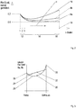
- FIG. 2 are courses according to the invention of a radially averaged degree of reaction 8a, 8b of a compressor of a turbomachine, in particular an aircraft engine, compared to a conventional course of a radially averaged degree of reaction 10 shown.
- the reaction rates 8a, 8b, 10 are in the longitudinal direction of the compressor or in the flow direction x of a main flow flowing through the turbomachine via a front compressor region 12, a middle compressor region 14 and a rear compressor region 16 outlined.
- the front compressor region 12 is formed on the stator side, for example, by three adjustable guide blade rows.
- the central compressor region 14 has a plurality of stator vanes which can not be adjusted on the stator side.
- the rear compressor section 16 has a stator outlet guide 18 in addition to a large number of non-adjustable rows of stator blades, in particular as the last row of guide vanes
- FIG. 2 shown expansions of the compressor areas 12, 14 and 16 in the flow direction x is purely exemplary and may of course also vary.
- the front compressor section 12 may also have fewer than three rows of vanes or more than three adjustable rows of vanes, such as five rows of vanes.
- the radially averaged degree of reaction 10 in the front compressor region 12 falls steeply from a maximum, for example 0.7, to a minimum, for example 0.6.
- the conventional degree of reaction 10 increases slowly to the outlet conductor grid 18 of the rear compressor region 16.
- all the guide vanes in the central compressor region 14 and in the rear compressor region 16 are heavily loaded and the efficiency in the rear compressor region 16 drops sharply.
- the degree of reaction 8a, 8b is now adjusted so that, after the steep drop in the front compressor region 12, from a maximum to a minimum over the middle compressor region 14 into the rear compressor region 16 and in particular to the outlet guide grille 18 is constant or almost constant Minimum, here 0.5, is held.
- Minimum here 0.5
- the stator load on the rear compressor region 16 is generally reduced and thus increases the efficiency.
- the degree of reaction gradients according to the invention can be achieved by carrying out either a stator-side and / or rotor-side side wall contouring, preferably a non-circumference-symmetrical side wall contouring, in the outlet guide grid 18 (degree of reaction 8b).
- the outlet guide grille 18 is designed in tandem construction (reaction degree 8a). This is possible the course of the reaction degree is always closer to the minimum than with pure sidewall contouring.
- a mean value 20 of the degree of reaction 8a, 8b at half the radial height between the compressor hub and the compressor housing is reduced compared to a mean value 22 with a linear radial profile 24.
- the linear profile 24 is such that a hub-side value 28 of the degree of reaction is smaller than a housing-side value 30 of the degree of reaction 8a, 8b.
Landscapes
- Engineering & Computer Science (AREA)
- Mechanical Engineering (AREA)
- General Engineering & Computer Science (AREA)
- Physics & Mathematics (AREA)
- Fluid Mechanics (AREA)
- Geometry (AREA)
- Structures Of Non-Positive Displacement Pumps (AREA)
Abstract
Description
- Die Erfindung betrifft ein Verfahren zum Betreiben eines Verdichters einer Strömungsmaschine, einen Verdichter einer Strömungsmaschine und eine Strömungsmaschine.
- In herkömmlichen Axialverdichtern von Strömungsmaschinen wie Flugtriebwerke und statischen Gasturbinen fällt ein radial gemittelter Reaktionsgrad im vorderen Verdichterbereich von einem eintrittsseitigen Maximum auf ein Minimum ab. Der lokale Reaktionsgrad lässt sich nach der folgenden Formel, basierend auf Metallwinkeln, vereinfacht berechnen:

- Die Winkel α1, α2, β1, β2 werden, wie in
Figur 1 dargestellt, zwischen Tangenten der jeweiligen Skelettlinie und einer axialen Strömungsrichtung x der Strömungsmaschine abgetragen. α1 wird von der Hinterkante einer Leitschaufel 2 einer Leitschaufelreihe n-1 abgetragen. α2 wird zur Anströmkante einer Leitschaufel 4 einer Leitschaufelreihe n hin abgetragen. β1 wird zur Anströmkante einer Laufschaufel 6 einer Laufschaufelreihe n hin abgetragen. β2 wird von der Hinterkante der Laufschaufel 6 der Laufschaufelreihe n abgetragen. Dabei läuft die Laufschaufel 6 bzw. die Laufschaufelreihe n in Umfangsrichtung u zwischen den Leitschaufeln 2, 4 bzw. den Leitschaufelreihen n-1, n hindurch. Der Buchstabe n kennzeichnet ganzzahlige Vielfache von 1, 2,.... Gewöhnlich deckt der Reaktionsgrad bei Verdichtern einen Bereich zwischen 0,5 und 1,0 ab. Turbinen decken gewöhnlich Reaktionsgrade von 0,0...0,05 bis 0,5 ab. Dem Abfallen des Reaktionsgrads stromaufwärts des ersten nichtverstellbaren Leitgitters folgt bei bekannten Strömungsmaschinen ein Anstieg des Reaktionsgrads bis zum Verdichteraustritt. Durch den Anstieg lässt sich im hinteren Verdichterbereich und insbesondere am Austrittsleitgitter des Verdichters ein Restdrall im Hauptstrom reduzieren, allerdings verursacht der Anstieg eine hohe Belastung der hinteren Stufen, was zu Wirkungsgradreduzierungen führt. - Aufgabe der Erfindung ist es, ein Verfahren zum Betreiben eines Verdichters einer Strömungsmaschine zu schaffen, der einen hohen Wirkungsgrad aufweist. Zudem ist es Aufgabe der Erfindung, einen Verdichter einer Strömungsmaschine mit einem hohen Wirkungsgrad, sowie eine Strömungsmaschine mit einem hohen Wirkungsgrad zu schaffen.
- Diese Aufgabe wird gelöst durch ein Verfahren mit den Merkmalen des Patentanspruchs 1, durch einen Verdichter mit den Merkmalen des Patentanspruchs 4 und durch eine Strömungsmaschine mit den Merkmalen des Patentanspruchs 7.
- Bei einem erfindungsgemäßen Verfahren zum Betreiben eines Verdichters einer Strömungsmaschine, beispielsweise ein Flugtriebwerk, wird in Richtung eines Hauptstroms betrachtet ein, insbesondere radial gemittelter, Reaktionsgrad, der in einem vorderen Verdichterbereich von einem Maximum auf eine Minimum abgefallen ist, über einen mittleren Verdichterbereich bis in einen hinteren Verdichterbereich konstant bzw. nahezu konstant gehalten, wobei im hinteren Verdichterbereich ein, insbesondere radial gemittelter, Reaktionsgrad eingestellt wird, der näher am Minimum als am Maximum liegt. Zudem wird im Mittelschnitt ein Restdrall von mindestens 47° eingestellt.
- Durch den niedrigen Reaktionsgrad bis in den hinteren Verdichterbereich und den somit nicht bzw. nicht wesentlich ansteigenden Reaktionsgrad ab der Verdichtermitte bis zum Verdichteraustritt werden die Rotor-Machzahlen niedrig gehalten. Dies führt zu einer Wirkungsgradverbesserung der Stufen. Die hinteren Stufen werden bis auf ein Austrittsleitgitter entlastet, wodurch die Stator-Schaufelzahlen reduziert werden können. Hierdurch wird eine Verbesserung des Verdichterwirkungsgrades gegenüber herkömmlichen Strömungsmaschinen erreicht. Der erfindungsgemäße Verdichter weist somit einen hohen Wirkungsgrad auf. Die Schaufeln können auch derart zueinander ausgerichtet werden, dass im hinteren Verdichterbereich ein Restdrall von 50° bis 60° abgebaut werden kann.
- Besonders günstige Ergebnisse lassen sich erzielen, wenn der radial gemittelte Reaktionsgrad vom Minimum bis zum hinteren Verdichterbereich nahe von 0,5 oder leicht höher, beispielweise bis zu 10% höher, eingestellt wird.
- Ein Wert des Reaktionsgrads auf halber radialer Höhe zwischen der Verdichternabe und dem Verdichtergehäuse kann gegenüber einem Mittelwert bei linearem radialen Verlauf reduziert werden. Durch diese Maßnahme wird der Reaktionsgrad in den Seitenwandbereichen des von dem Hauptstrom durchströmten Ringraums angehoben, was eine Stabilisierung der Grenzschichten und somit eine Reduzierung von Seitenwandverlusten bewirkt. Hierdurch steigt wiederum der Pumpgrenzabstand.
- Ein erfindungsgemäßer Verdichter einer Strömungsmaschine hat eine derartige Schaufelausrichtung bzw. Schaufelanordnung, dass im hinteren Verdichterbereich ein Reaktionsgrad eingestellt ist, der näher am Minimum als am Maximum liegt und im Mittelschnitt ein Restdrall von mindestens 47° vorliegt.
- Zum Niedrighalten des Reaktionsgrades und zum Abbauen des Restdralls kann ein Austrittsleitgitter beispielsweise eine nabenseitige und/oder gehäuseseitige Seitenwandkonturierung haben. Bevorzugterweise ist die zumindest eine Seitenwandkonturierung nichtumfangssymmetrisch.
- Alternativ oder zusätzlich zur Seitenwandkonturierung kann der Verdichter im hinteren Verdichterbereich zum Einstellen des niedrigen Reaktionsgrades und zum Abbauen des Restdralls ein Austrittsleitgitter in Tandemausführung mit zwei, drei oder mehr Schaufelreihen haben.
- Eine bevorzugte Strömungsmaschine hat einen erfindungsgemäßen Verdichter bzw. einen Verdichter, der nach dem erfindungsgemäßen Verfahren betrieben wird. Hierdurch zeichnet sich die Strömungsmaschine durch einen hohen Wirkungsgrad aus.
- Sonstige vorteilhafte Ausführungsbeispiele der Erfindung sind Gegenstand weiterer Unteransprüche.
- Im Folgenden werden bevorzugte Ausführungsbeispiele der Erfindung anhand von schematischen Darstellungen näher erläutert. Es zeigen:
-
Figur 1 ein Schaubild zur Definition eines verdichterseitigen Reaktionsgrades, -
Figur 2 erfindungsgemäße Verläufe des radial gemittelten Reaktionsgrads in Verdichterlängsrichtung im Vergleich zu einem Verlauf eines bekannten verdichterseitigen Reaktionsgrades, und -
Figur 3 einen radialen Verlauf eines erfindungsgemäßen Reaktionsgrads im Vergleich zu einem radialen Verlauf eines bekannten verdichterseitigen Reaktionsgrades. - Wie bereits eingangs erwähnt, ist in
Figur 1 dargestellt, wie sich ein verdichterseitiger Reaktionsgrad einer Strömungsmaschine berechnen lässt. Diese Berechnung bzw. dieses Verständnis wird auch den erfindungsgemäßen Reaktionsgraden zugrunde gelegt. - Der lokale Reaktionsgrad R berechnet sich demnach nach der folgenden Formel:
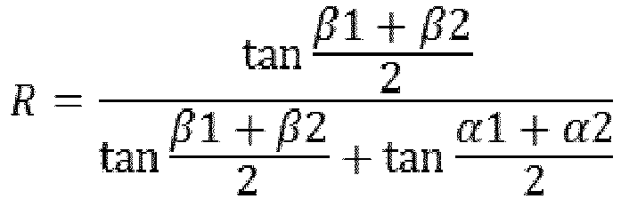
- Die Winkel α1, α2, β1, β2 werden, wie in
Figur 1 dargestellt, zwischen Tangenten der jeweiligen Skelettlinie und einer axialen Strömungsrichtung x der Strömungsmaschine abgetragen. α1 wird von der Hinterkante einer Leitschaufel 2 einer Leitschaufelreihe n-1 abgetragen. α2 wird zur Anströmkante einer Leitschaufel 4 einer Leitschaufelreihe n hin abgetragen. β1 wird zur Anströmkante einer Laufschaufel 6 einer Laufschaufelreihe n hin abgetragen. β2 wird von der Hinterkante der Laufschaufel 6 der Laufschaufelreihe n abgetragen. Dabei läuft die Laufschaufel 6 bzw. die Laufschaufelreihe n in Umfangsrichtung u zwischen den Leitschaufeln 2, 4 bzw. den Leitschaufelreihen n-1, n hindurch. Der Buchstabe n kennzeichnet ganzzahlige Vielfache von 1, 2,.... - In
Figur 2 sind erfindungsgemäße Verläufe eines radial gemittelten Reaktionsgrades 8a, 8b eines Verdichters einer Strömungsmaschine, insbesondere ein Flugtriebwerk, im Vergleich zu einem herkömmlichen Verlauf eines radial gemittelten Reaktionsgrads 10 gezeigt. - Die Reaktionsgrade 8a, 8b, 10 sind in Längsrichtung des Verdichters bzw. in Strömungsrichtung x eines die Strömungsmaschine durchströmenden Hauptstroms über einen vorderen Verdichterbereich 12, einen mittleren Verdichterbereich 14 und einen hinteren Verdichterbereich 16 skizziert. Der vordere Verdichterbereich 12 wird statorseitig beispielsweise von drei verstellbaren Leitschaufelreihen gebildet. Der mittlere Verdichterbereich 14 weist statorseitig eine Vielzahl von nichtverstellbaren Leitschaufelreihen auf. Der hintere Verdichterbereich 16 hat statorseitig neben einer Vielzahl von nichtverstellbaren Leitschaufelreihen insbesondere als letzte Leitschaufelreihe ein Austrittsleitgitter 18. Die in
Figur 2 gezeigte Ausdehnungen der Verdichterbereiche 12, 14 und 16 in Strömungsrichtung x ist rein exemplarisch und kann selbstverständlich auch variieren. So kann beispielsweise der vordere Verdichterbereich 12 auch weniger als drei Leitschaufelreihen oder mehr als drei verstellbare Leitschaufelreihen wie beispielsweise fünf Leitschaufelreihen aufweisen. - Herkömmlicherweise fällt der radial gemittelte Reaktionsgrad 10 im vorderen Verdichterbereich 12 von einem Maximum, beispielsweise 0,7, steil auf ein Minimum, beispielsweise 0,6, ab. Mit Beginn des mittleren Verdichterbereichs 14 steigt der herkömmliche Reaktionsgrad 10 langsam bis zum Austrittsleitergitter 18 des hinteren Verdichterbereichs 16. Hierdurch werden sämtliche Leitschaufeln im mittleren Verdichterbereich 14 und im hinteren Verdichterbereich 16 stark belastet und der Wirkungsgrad im hinteren Verdichterbereich 16 sinkt stark ab.
- Erfindungsgemäß wird der Reaktionsgrad 8a, 8b nun so eingestellt, dass er nach dem steilen Abfall im vorderen Verdichterbereich 12 von einem Maximum auf ein Minimum über dem mittleren Verdichterbereich 14 bis in den hinteren Verdichterbereich 16 und insbesondere bis zum Austrittsleitgitter 18 konstant bzw. nahezu konstant beim Minimum, hier 0,5, gehalten wird. Hierdurch wird die statorseitige Belastung des hinteren Verdichterbereichs 16 generell reduziert und somit der Wirkungsgrad gesteigert. Es wird lediglich das Austrittsleitgitter 18 durch den abzubauenden Restdrall des Hauptstroms stark belastet. Bevorzugterweise liegt im Mittelschnitt ein Restdrall von mindestens 47° bezogen auf die Strömungsrichtung x vor. Möglich sind auch Restdrallwinkel von 50° bis 60°.
- Konstruktiv lassen sich die erfindungsgemäßen Reaktionsgradverläufe dadurch erreichen, dass in dem Austrittsleitgitter 18 entweder eine statorseitige und/oder rotorseitige Seitenwandkonturierung, bevorzugterweise eine nichtumfangssymmetrische Seitenwandkonturierung, vorgenommen wird (Reaktionsgrad 8b). Alternativ oder ergänzend ist das Austrittsleitgitter 18 in Tandembauweise ausgeführt (Reaktionsgrad 8a). Hierdurch lässt sich der Reaktionsgradverlauf grundsätzlich näher am Minimum halten als bei reiner Seitenwandkonturierung.
- Gemäß
Figur 3 wird es bevorzugt, wenn ein mittlerer Wert 20 des Reaktionsgrads 8a, 8b auf halber radialer Höhe zwischen der Verdichternabe und dem Verdichtergehäuse gegenüber einem Mittelwert 22 bei linearem radialen Verlauf 24 reduziert wird. Der lineare Verlauf 24 ist dabei derart, dass ein nabenseitiger Wert 28 des Reaktionsgrads kleiner als ein gehäuseseitiger Wert 30 des Reaktionsgrads 8a, 8b ist. Durch das Absenken des mittleren Reaktionsgradwertes ergibt sich ein wannenartiger radialer Verlauf 26 der Reaktionsgrade 8a, 8b, wodurch die seitenwandseitigen Reaktionsgradwerte 30, 28 gegenüber dem linearen Verlauf 24 heraufgesetzt werden. Dies bewirkt eine Stabilisierung der Seitenwandgrenzschicht und führt somit zu einer Steigerung des Pumpgrenzabstandes, so dass die Stabilität des Verdichters aufgrund der Senkung des mittleren Wertes des Reaktionsgrades 8a, 8b gegenüber einem ursprünglichen linearen Verlauf 24 erhöht wird. - Offenbart ist ein Verfahren zum Betreiben eines Verdichters einer Strömungsmaschine, wobei in Richtung eines Hauptstroms betrachtet ein, insbesondere radial gemittelter, Reaktionsgrad, der in einem vorderen Verdichterbereich von einem Maximum auf ein Minimum abgefallen ist, über einen mittleren Verdichterbereich bis in einen hinteren Verdichterbereich konstant bzw. nahezu konstant gehalten wird, wobei im hinteren Verdichterbereich ein, insbesondere radial gemittelter, Reaktionsgrad eingestellt wird, der näher am Minium als am Maximum liegt, und im Mittelschnitt ein Restdrall von mindestens 47° vorliegt, ein Verdichter und eine Strömungsmaschine.
-
- 2
- Leitschaufel - Stufe n-1
- 4
- Leitschaufel - Stufe n
- 6
- Laufschaufel - Stufe n
- 8a
- Reaktionsgrad
- 8b
- Reaktionsgrad
- 10
- Reaktionsgrad
- 12
- vorderer Verdichterbereich
- 14
- mittlerer Verdichterbereich
- 16
- hinterer Verdichterbereich
- 18
- Austrittsleitgitter
- 20
- mittlerer Wert
- 22
- Mittelwert
- 24
- linearer Verlauf
- 26
- wannenartiger Verlauf
- 28
- nabenseitiger Wert
- 30
- gehäuseseitiger Wert
- R
- Reaktionsgrad
- x
- Strömungsrichtung
- u
- Umfangsrichtung
Claims (7)
- Verfahren zum Betreiben eines Verdichters einer Strömungsmaschine, wobei in Richtung eines Hauptstroms betrachtet ein, insbesondere radial gemittelter, Reaktionsgrad (8a, 8b), der in einem vorderen Verdichterbereich (12) von einem Maximum auf ein Minimum abgefallen ist, über einen mittleren Verdichterbereich (14) bis in einen hinteren Verdichterbereich (16) konstant bzw. nahezu konstant gehalten wird, wobei im hinteren Verdichterbereich (16) ein, insbesondere radial gemittelter, Reaktionsgrad (8a, 8b) eingestellt wird, der näher am Minium als am Maximum liegt, und im Mittelschnitt ein Restdrall von mindestens 47° eingestellt wird.
- Verfahren nach Patentanspruch 1, wobei der Reaktionsgrad (8a, 8b) gleich 0,5 oder leicht höher eingestellt wird.
- Verfahren nach Patentanspruch 1 oder 2, wobei ein Wert (20) des Reaktionsgrads (8a, 8b) auf halber radialer Höhe zwischen einer Verdichternabe und dem Verdichtergehäuse gegenüber einem Mittelwert (22) bei linearem radialen Verlauf (24) reduziert wird.
- Verdichter einer Strömungsmaschine zum Durchführen eines Verfahrens nach Patentanspruch 1, 2 oder 3.
- Verdichter nach Patentanspruch 4, wobei der Verdichter im hinteren Verdichterbereich (16) eine nabenseitige und/oder gehäuseseitige Seitenwandkonturierung hat.
- Verdichter nach Patentanspruch 4 oder 5, wobei im hinteren Verdichterbereich (16) ein Austrittsleitgitter (18) in Tandemausführung angeordnet ist.
- Strömungsmaschine, dessen Verdichter mit einem Verfahren nach Patentanspruchs 1, 2 oder 3 betrieben wird bzw. mit einem Verdichter nach den Patentansprüchen 4, 5 oder 6.
Applications Claiming Priority (1)
| Application Number | Priority Date | Filing Date | Title |
|---|---|---|---|
| DE102015223210.7A DE102015223210B3 (de) | 2015-11-24 | 2015-11-24 | Verdichter, Verfahren und Strömungsmaschine |
Publications (2)
| Publication Number | Publication Date |
|---|---|
| EP3173581A1 true EP3173581A1 (de) | 2017-05-31 |
| EP3173581B1 EP3173581B1 (de) | 2020-12-02 |
Family
ID=57189960
Family Applications (1)
| Application Number | Title | Priority Date | Filing Date |
|---|---|---|---|
| EP16195410.2A Active EP3173581B1 (de) | 2015-11-24 | 2016-10-25 | Verdichter einer strömungsmaschine |
Country Status (3)
| Country | Link |
|---|---|
| US (1) | US10641288B2 (de) |
| EP (1) | EP3173581B1 (de) |
| DE (1) | DE102015223210B3 (de) |
Families Citing this family (1)
| Publication number | Priority date | Publication date | Assignee | Title |
|---|---|---|---|---|
| DE102015223212A1 (de) * | 2015-11-24 | 2017-05-24 | MTU Aero Engines AG | Verfahren, Verdichter und Strömungsmaschine |
Citations (3)
| Publication number | Priority date | Publication date | Assignee | Title |
|---|---|---|---|---|
| GB710300A (en) * | 1950-12-02 | 1954-06-09 | Francis Henry Keast | Axial flow compressor |
| GB1153134A (en) * | 1965-07-28 | 1969-05-21 | Anthony Sydney De Forge-Dedman | Axial Flow Compressor |
| EP2431577A2 (de) * | 2010-09-16 | 2012-03-21 | Hitachi Ltd. | Axialverdichter, Gasturbinensystem mit dem Axialverdichter und Verfahren zur Modifizierung des Axialverdichters |
Family Cites Families (10)
| Publication number | Priority date | Publication date | Assignee | Title |
|---|---|---|---|---|
| DE312856C (de) * | ||||
| CH219738A (de) * | 1940-11-19 | 1942-02-28 | Sulzer Ag | Mehrstufiger Axialverdichter. |
| US3248081A (en) * | 1964-12-29 | 1966-04-26 | Gen Electric | Axial locating means for airfoils |
| US4652208A (en) | 1985-06-03 | 1987-03-24 | General Electric Company | Actuating lever for variable stator vanes |
| US4989406A (en) * | 1988-12-29 | 1991-02-05 | General Electric Company | Turbine engine assembly with aft mounted outlet guide vanes |
| DE19701020A1 (de) | 1997-01-14 | 1998-07-23 | Siemens Ag | Dampfturbine |
| DE102009037956B4 (de) | 2009-08-18 | 2024-06-06 | MTU Aero Engines AG | Turbinenaustrittsgehäuse |
| DE102011120167A1 (de) * | 2011-12-06 | 2013-06-06 | Daimler Ag | Verdichter für einen Abgasturbolader,insbesondere eines Kraftwagens |
| EP2626515B1 (de) | 2012-02-10 | 2020-06-17 | MTU Aero Engines GmbH | Tandem-Schaufelgruppenanordnung |
| EP3032032B1 (de) | 2014-12-12 | 2019-06-12 | MTU Aero Engines GmbH | Austrittsleitgitter und Mantelstromtriebwerk mit einem Austrittsleitgitter |
-
2015
- 2015-11-24 DE DE102015223210.7A patent/DE102015223210B3/de not_active Expired - Fee Related
-
2016
- 2016-10-25 EP EP16195410.2A patent/EP3173581B1/de active Active
- 2016-11-22 US US15/359,113 patent/US10641288B2/en active Active
Patent Citations (3)
| Publication number | Priority date | Publication date | Assignee | Title |
|---|---|---|---|---|
| GB710300A (en) * | 1950-12-02 | 1954-06-09 | Francis Henry Keast | Axial flow compressor |
| GB1153134A (en) * | 1965-07-28 | 1969-05-21 | Anthony Sydney De Forge-Dedman | Axial Flow Compressor |
| EP2431577A2 (de) * | 2010-09-16 | 2012-03-21 | Hitachi Ltd. | Axialverdichter, Gasturbinensystem mit dem Axialverdichter und Verfahren zur Modifizierung des Axialverdichters |
Also Published As
| Publication number | Publication date |
|---|---|
| EP3173581B1 (de) | 2020-12-02 |
| US10641288B2 (en) | 2020-05-05 |
| US20170146025A1 (en) | 2017-05-25 |
| DE102015223210B3 (de) | 2017-04-27 |
Similar Documents
| Publication | Publication Date | Title |
|---|---|---|
| EP2626515B1 (de) | Tandem-Schaufelgruppenanordnung | |
| EP1927723B1 (de) | Stator-Stufe eines Axialverdichters einer Strömungsmaschine mit Querlamellen zur Wirkungsgradsteigerung | |
| DE69601283T2 (de) | Strömungsleitenden Vorrichtung für ein Gasturbinentriebwerk | |
| EP2473743B1 (de) | Verdichterlaufschaufel für einen axialverdichter | |
| EP2626514B1 (de) | Strömungsmaschine | |
| EP2103792B1 (de) | Gasturbinenverdichter mit Zapfluftentnahmevorrichtung | |
| EP2696029B1 (de) | Schaufelgitter mit Seitenwandkonturierung und Strömungsmaschine | |
| EP0799973B1 (de) | Wandkontur für eine axiale Strömungsmaschine | |
| DE102008011645A1 (de) | Strömungsarbeitsmaschine mit Rotoren mit niedrigen Rotoraustrittswinkeln | |
| EP2927503B1 (de) | Gasturbinenverdichter, Flugtriebwerk und Auslegungsverfahren | |
| CH697806A2 (de) | Turbinenschaufel-Deckbandkantenprofil. | |
| WO2010007137A1 (de) | Axialturbomaschine mit geringen spaltverlusten | |
| DE102009036406A1 (de) | Schaufelblatt | |
| DE102014206217B4 (de) | Verdichtungsgitter für einen Axialverdichter | |
| DE102018108940A1 (de) | Turbofantriebwerk für ein Luftfahrzeug | |
| EP3032032A1 (de) | Austrittsleitgitter und Mantelstromtriebwerk mit einem Austrittsleitgitter | |
| EP3401504B1 (de) | Schaufelgitter | |
| EP1865148B1 (de) | Strömungsarbeitsmaschine mit Rotoren hoher spezifischer Energieabgabe | |
| EP3388626B1 (de) | Konturierung einer schaufelgitterplattform | |
| DE102015223210B3 (de) | Verdichter, Verfahren und Strömungsmaschine | |
| DE10255389A1 (de) | Niederdruckdampfturbine mit Mehrkanal-Diffusor | |
| EP3173629B1 (de) | Verfahren für und verdichter einer strömungsmaschine | |
| EP3390833B1 (de) | Verdichterlaufschaufel, verdichter und verfahren zum profilieren der verdichterlaufschaufel | |
| DE102014206216B4 (de) | Verdichtungsgitter für einen Axialverdichter | |
| EP2530330B1 (de) | Laufschaufel für einen Verdichter einer Turbomaschine, Verdichter sowie Turbomaschine |
Legal Events
| Date | Code | Title | Description |
|---|---|---|---|
| PUAI | Public reference made under article 153(3) epc to a published international application that has entered the european phase |
Free format text: ORIGINAL CODE: 0009012 |
|
| STAA | Information on the status of an ep patent application or granted ep patent |
Free format text: STATUS: THE APPLICATION HAS BEEN PUBLISHED |
|
| AK | Designated contracting states |
Kind code of ref document: A1 Designated state(s): AL AT BE BG CH CY CZ DE DK EE ES FI FR GB GR HR HU IE IS IT LI LT LU LV MC MK MT NL NO PL PT RO RS SE SI SK SM TR |
|
| AX | Request for extension of the european patent |
Extension state: BA ME |
|
| STAA | Information on the status of an ep patent application or granted ep patent |
Free format text: STATUS: REQUEST FOR EXAMINATION WAS MADE |
|
| 17P | Request for examination filed |
Effective date: 20171130 |
|
| RBV | Designated contracting states (corrected) |
Designated state(s): AL AT BE BG CH CY CZ DE DK EE ES FI FR GB GR HR HU IE IS IT LI LT LU LV MC MK MT NL NO PL PT RO RS SE SI SK SM TR |
|
| STAA | Information on the status of an ep patent application or granted ep patent |
Free format text: STATUS: EXAMINATION IS IN PROGRESS |
|
| 17Q | First examination report despatched |
Effective date: 20180727 |
|
| REG | Reference to a national code |
Ref country code: DE Ref legal event code: R079 Ref document number: 502016011829 Country of ref document: DE Free format text: PREVIOUS MAIN CLASS: F01D0005140000 Ipc: F04D0029320000 |
|
| RIC1 | Information provided on ipc code assigned before grant |
Ipc: F04D 19/02 20060101ALI20190910BHEP Ipc: F04D 29/32 20060101AFI20190910BHEP Ipc: F01D 5/14 20060101ALI20190910BHEP Ipc: F04D 29/54 20060101ALI20190910BHEP |
|
| GRAP | Despatch of communication of intention to grant a patent |
Free format text: ORIGINAL CODE: EPIDOSNIGR1 |
|
| STAA | Information on the status of an ep patent application or granted ep patent |
Free format text: STATUS: GRANT OF PATENT IS INTENDED |
|
| INTG | Intention to grant announced |
Effective date: 20200610 |
|
| GRAS | Grant fee paid |
Free format text: ORIGINAL CODE: EPIDOSNIGR3 |
|
| GRAA | (expected) grant |
Free format text: ORIGINAL CODE: 0009210 |
|
| STAA | Information on the status of an ep patent application or granted ep patent |
Free format text: STATUS: THE PATENT HAS BEEN GRANTED |
|
| AK | Designated contracting states |
Kind code of ref document: B1 Designated state(s): AL AT BE BG CH CY CZ DE DK EE ES FI FR GB GR HR HU IE IS IT LI LT LU LV MC MK MT NL NO PL PT RO RS SE SI SK SM TR |
|
| REG | Reference to a national code |
Ref country code: GB Ref legal event code: FG4D Free format text: NOT ENGLISH |
|
| REG | Reference to a national code |
Ref country code: AT Ref legal event code: REF Ref document number: 1341233 Country of ref document: AT Kind code of ref document: T Effective date: 20201215 Ref country code: CH Ref legal event code: EP |
|
| REG | Reference to a national code |
Ref country code: IE Ref legal event code: FG4D Free format text: LANGUAGE OF EP DOCUMENT: GERMAN |
|
| REG | Reference to a national code |
Ref country code: DE Ref legal event code: R096 Ref document number: 502016011829 Country of ref document: DE |
|
| PG25 | Lapsed in a contracting state [announced via postgrant information from national office to epo] |
Ref country code: FI Free format text: LAPSE BECAUSE OF FAILURE TO SUBMIT A TRANSLATION OF THE DESCRIPTION OR TO PAY THE FEE WITHIN THE PRESCRIBED TIME-LIMIT Effective date: 20201202 Ref country code: GR Free format text: LAPSE BECAUSE OF FAILURE TO SUBMIT A TRANSLATION OF THE DESCRIPTION OR TO PAY THE FEE WITHIN THE PRESCRIBED TIME-LIMIT Effective date: 20210303 Ref country code: NO Free format text: LAPSE BECAUSE OF FAILURE TO SUBMIT A TRANSLATION OF THE DESCRIPTION OR TO PAY THE FEE WITHIN THE PRESCRIBED TIME-LIMIT Effective date: 20210302 Ref country code: RS Free format text: LAPSE BECAUSE OF FAILURE TO SUBMIT A TRANSLATION OF THE DESCRIPTION OR TO PAY THE FEE WITHIN THE PRESCRIBED TIME-LIMIT Effective date: 20201202 |
|
| REG | Reference to a national code |
Ref country code: NL Ref legal event code: MP Effective date: 20201202 |
|
| PG25 | Lapsed in a contracting state [announced via postgrant information from national office to epo] |
Ref country code: SE Free format text: LAPSE BECAUSE OF FAILURE TO SUBMIT A TRANSLATION OF THE DESCRIPTION OR TO PAY THE FEE WITHIN THE PRESCRIBED TIME-LIMIT Effective date: 20201202 Ref country code: BG Free format text: LAPSE BECAUSE OF FAILURE TO SUBMIT A TRANSLATION OF THE DESCRIPTION OR TO PAY THE FEE WITHIN THE PRESCRIBED TIME-LIMIT Effective date: 20210302 Ref country code: PL Free format text: LAPSE BECAUSE OF FAILURE TO SUBMIT A TRANSLATION OF THE DESCRIPTION OR TO PAY THE FEE WITHIN THE PRESCRIBED TIME-LIMIT Effective date: 20201202 Ref country code: LV Free format text: LAPSE BECAUSE OF FAILURE TO SUBMIT A TRANSLATION OF THE DESCRIPTION OR TO PAY THE FEE WITHIN THE PRESCRIBED TIME-LIMIT Effective date: 20201202 |
|
| PG25 | Lapsed in a contracting state [announced via postgrant information from national office to epo] |
Ref country code: HR Free format text: LAPSE BECAUSE OF FAILURE TO SUBMIT A TRANSLATION OF THE DESCRIPTION OR TO PAY THE FEE WITHIN THE PRESCRIBED TIME-LIMIT Effective date: 20201202 Ref country code: NL Free format text: LAPSE BECAUSE OF FAILURE TO SUBMIT A TRANSLATION OF THE DESCRIPTION OR TO PAY THE FEE WITHIN THE PRESCRIBED TIME-LIMIT Effective date: 20201202 |
|
| REG | Reference to a national code |
Ref country code: LT Ref legal event code: MG9D |
|
| PG25 | Lapsed in a contracting state [announced via postgrant information from national office to epo] |
Ref country code: SK Free format text: LAPSE BECAUSE OF FAILURE TO SUBMIT A TRANSLATION OF THE DESCRIPTION OR TO PAY THE FEE WITHIN THE PRESCRIBED TIME-LIMIT Effective date: 20201202 Ref country code: RO Free format text: LAPSE BECAUSE OF FAILURE TO SUBMIT A TRANSLATION OF THE DESCRIPTION OR TO PAY THE FEE WITHIN THE PRESCRIBED TIME-LIMIT Effective date: 20201202 Ref country code: PT Free format text: LAPSE BECAUSE OF FAILURE TO SUBMIT A TRANSLATION OF THE DESCRIPTION OR TO PAY THE FEE WITHIN THE PRESCRIBED TIME-LIMIT Effective date: 20210405 Ref country code: SM Free format text: LAPSE BECAUSE OF FAILURE TO SUBMIT A TRANSLATION OF THE DESCRIPTION OR TO PAY THE FEE WITHIN THE PRESCRIBED TIME-LIMIT Effective date: 20201202 Ref country code: LT Free format text: LAPSE BECAUSE OF FAILURE TO SUBMIT A TRANSLATION OF THE DESCRIPTION OR TO PAY THE FEE WITHIN THE PRESCRIBED TIME-LIMIT Effective date: 20201202 Ref country code: CZ Free format text: LAPSE BECAUSE OF FAILURE TO SUBMIT A TRANSLATION OF THE DESCRIPTION OR TO PAY THE FEE WITHIN THE PRESCRIBED TIME-LIMIT Effective date: 20201202 Ref country code: EE Free format text: LAPSE BECAUSE OF FAILURE TO SUBMIT A TRANSLATION OF THE DESCRIPTION OR TO PAY THE FEE WITHIN THE PRESCRIBED TIME-LIMIT Effective date: 20201202 |
|
| REG | Reference to a national code |
Ref country code: DE Ref legal event code: R097 Ref document number: 502016011829 Country of ref document: DE |
|
| PG25 | Lapsed in a contracting state [announced via postgrant information from national office to epo] |
Ref country code: IS Free format text: LAPSE BECAUSE OF FAILURE TO SUBMIT A TRANSLATION OF THE DESCRIPTION OR TO PAY THE FEE WITHIN THE PRESCRIBED TIME-LIMIT Effective date: 20210402 |
|
| PLBE | No opposition filed within time limit |
Free format text: ORIGINAL CODE: 0009261 |
|
| STAA | Information on the status of an ep patent application or granted ep patent |
Free format text: STATUS: NO OPPOSITION FILED WITHIN TIME LIMIT |
|
| PG25 | Lapsed in a contracting state [announced via postgrant information from national office to epo] |
Ref country code: AL Free format text: LAPSE BECAUSE OF FAILURE TO SUBMIT A TRANSLATION OF THE DESCRIPTION OR TO PAY THE FEE WITHIN THE PRESCRIBED TIME-LIMIT Effective date: 20201202 Ref country code: IT Free format text: LAPSE BECAUSE OF FAILURE TO SUBMIT A TRANSLATION OF THE DESCRIPTION OR TO PAY THE FEE WITHIN THE PRESCRIBED TIME-LIMIT Effective date: 20201202 |
|
| 26N | No opposition filed |
Effective date: 20210903 |
|
| PG25 | Lapsed in a contracting state [announced via postgrant information from national office to epo] |
Ref country code: DK Free format text: LAPSE BECAUSE OF FAILURE TO SUBMIT A TRANSLATION OF THE DESCRIPTION OR TO PAY THE FEE WITHIN THE PRESCRIBED TIME-LIMIT Effective date: 20201202 Ref country code: SI Free format text: LAPSE BECAUSE OF FAILURE TO SUBMIT A TRANSLATION OF THE DESCRIPTION OR TO PAY THE FEE WITHIN THE PRESCRIBED TIME-LIMIT Effective date: 20201202 |
|
| PG25 | Lapsed in a contracting state [announced via postgrant information from national office to epo] |
Ref country code: ES Free format text: LAPSE BECAUSE OF FAILURE TO SUBMIT A TRANSLATION OF THE DESCRIPTION OR TO PAY THE FEE WITHIN THE PRESCRIBED TIME-LIMIT Effective date: 20201202 |
|
| REG | Reference to a national code |
Ref country code: CH Ref legal event code: PL |
|
| PG25 | Lapsed in a contracting state [announced via postgrant information from national office to epo] |
Ref country code: IS Free format text: LAPSE BECAUSE OF FAILURE TO SUBMIT A TRANSLATION OF THE DESCRIPTION OR TO PAY THE FEE WITHIN THE PRESCRIBED TIME-LIMIT Effective date: 20210402 |
|
| REG | Reference to a national code |
Ref country code: BE Ref legal event code: MM Effective date: 20211031 |
|
| PG25 | Lapsed in a contracting state [announced via postgrant information from national office to epo] |
Ref country code: MC Free format text: LAPSE BECAUSE OF FAILURE TO SUBMIT A TRANSLATION OF THE DESCRIPTION OR TO PAY THE FEE WITHIN THE PRESCRIBED TIME-LIMIT Effective date: 20201202 |
|
| PG25 | Lapsed in a contracting state [announced via postgrant information from national office to epo] |
Ref country code: LU Free format text: LAPSE BECAUSE OF NON-PAYMENT OF DUE FEES Effective date: 20211025 Ref country code: BE Free format text: LAPSE BECAUSE OF NON-PAYMENT OF DUE FEES Effective date: 20211031 |
|
| PG25 | Lapsed in a contracting state [announced via postgrant information from national office to epo] |
Ref country code: LI Free format text: LAPSE BECAUSE OF NON-PAYMENT OF DUE FEES Effective date: 20211031 Ref country code: CH Free format text: LAPSE BECAUSE OF NON-PAYMENT OF DUE FEES Effective date: 20211031 |
|
| PG25 | Lapsed in a contracting state [announced via postgrant information from national office to epo] |
Ref country code: IE Free format text: LAPSE BECAUSE OF NON-PAYMENT OF DUE FEES Effective date: 20211025 |
|
| REG | Reference to a national code |
Ref country code: AT Ref legal event code: MM01 Ref document number: 1341233 Country of ref document: AT Kind code of ref document: T Effective date: 20211025 |
|
| PG25 | Lapsed in a contracting state [announced via postgrant information from national office to epo] |
Ref country code: AT Free format text: LAPSE BECAUSE OF NON-PAYMENT OF DUE FEES Effective date: 20211025 |
|
| PG25 | Lapsed in a contracting state [announced via postgrant information from national office to epo] |
Ref country code: HU Free format text: LAPSE BECAUSE OF FAILURE TO SUBMIT A TRANSLATION OF THE DESCRIPTION OR TO PAY THE FEE WITHIN THE PRESCRIBED TIME-LIMIT; INVALID AB INITIO Effective date: 20161025 |
|
| PG25 | Lapsed in a contracting state [announced via postgrant information from national office to epo] |
Ref country code: CY Free format text: LAPSE BECAUSE OF FAILURE TO SUBMIT A TRANSLATION OF THE DESCRIPTION OR TO PAY THE FEE WITHIN THE PRESCRIBED TIME-LIMIT Effective date: 20201202 |
|
| PG25 | Lapsed in a contracting state [announced via postgrant information from national office to epo] |
Ref country code: MK Free format text: LAPSE BECAUSE OF FAILURE TO SUBMIT A TRANSLATION OF THE DESCRIPTION OR TO PAY THE FEE WITHIN THE PRESCRIBED TIME-LIMIT Effective date: 20201202 |
|
| PG25 | Lapsed in a contracting state [announced via postgrant information from national office to epo] |
Ref country code: TR Free format text: LAPSE BECAUSE OF FAILURE TO SUBMIT A TRANSLATION OF THE DESCRIPTION OR TO PAY THE FEE WITHIN THE PRESCRIBED TIME-LIMIT Effective date: 20201202 |
|
| PG25 | Lapsed in a contracting state [announced via postgrant information from national office to epo] |
Ref country code: MT Free format text: LAPSE BECAUSE OF FAILURE TO SUBMIT A TRANSLATION OF THE DESCRIPTION OR TO PAY THE FEE WITHIN THE PRESCRIBED TIME-LIMIT Effective date: 20201202 |
|
| PGFP | Annual fee paid to national office [announced via postgrant information from national office to epo] |
Ref country code: DE Payment date: 20251020 Year of fee payment: 10 |
|
| PGFP | Annual fee paid to national office [announced via postgrant information from national office to epo] |
Ref country code: GB Payment date: 20251024 Year of fee payment: 10 |
|
| PGFP | Annual fee paid to national office [announced via postgrant information from national office to epo] |
Ref country code: FR Payment date: 20251027 Year of fee payment: 10 |